

Page 1

Video Disk Unit
3-620-597-12 (1)
Operating Instructions
Before operating the unit, please read this manual
thoroughly and retain it for future reference.
DSR-DU1
© 2002 Sony Corporation
Page 2

WARNING
To prevent fire or shock hazard, do not
expose the unit to rain or moisture.
To avoid electrical shock, do not open the
cabinet. Refer servicing to qualified
personnel only.
CAUTION
Danger of explosion if battery is incorrectly replaced.
Replace only with the same or equivalent type
recommended by the manufacturer.
Dispose of used batteries according to the
manufacturer’s instructions.
ADVARSEL!
Lithiumbatteri-Eksplosionsfare ved fejlagtig
håndtering.
Udskiftning må kun ske med batteri
af samme fabrikat og type.
Levér det brugte batteri tilbage til leverandøren.
ADVARSEL
Lithiumbatteri - Eksplosjonsfare.
Ved utskifting benyttes kun batteri som
anbefalt av apparatfabrikanten.
Brukt batteri returneres
apparatleverandøren.
For customers in the USA
This equipment has been tested and found to comply
with the limits for a Class A digital device, pursuant to
Part 15 of the FCC Rules. These limits are designed to
provide reasonable protection against harmful
interference when the equipment is operated in a
commercial environment. This equipment generates,
uses, and can radiate radio frequency energy and, if not
installed and used in accordance with the instruction
manual, may cause harmful interference to radio
communications. Operation of this equipment in a
residential area is likely to cause harmful interference in
which case the user will be required to correct the
interference at his own expense.
You are cautioned that any changes or modifications not
expressly approved in this manual could void your
authority to operate this equipment.
The shielded interface cable recommended in this
manual must be used with this equipment in order to
comply with the limits for a digital device pursuant to
Subpart B of Part 15 of FCC Rules.
For customers in Europe
This product with the CE marking complies with the
EMC Directive (89/336/EEC) issued by the
Commission of the European Community.
Compliance with these directive implies conformity to
the following European standards:
EN55103-1: Electromagnetic Interference (Emission)
EN55103-2: Electromagnetic Susceptibility (Immunity)
This product is intended for use in the following
Electromagnetic Environment(s):
E1 (residential), E2 (commercial and light industrial),
E3 (urban outdoors) and E4 (controlled EMC
environment, ex. TV studio).
VARNING
Voor de Klanten in Nederland
Explosionsfara vid felaktigt batteribyte.
Använd samma batterityp eller en likvärdig typ
som rekommenderas av apparattillverkaren.
Kassera använt batteri enligt gällande
föreskrifter.
Gooi de batterij niet weg maar lever deze in als klein
chemisch afval (KCA).
VAROITUS
Paristo voi räjähtää jos se on virheellisesti
asennettu.
Vaihda paristo ainoastaan laitevalmistajan
suosittelemaan tyyppiin.
Hävitä käytetty paristo valmistajan ohjeiden
mukaisesti.
2
Page 3

Table of Contents
Overview ................................................................. 4
Features of This Unit .......................................... 4
Supported Camcorders .......................................4
Using the CD-ROM Manual .............................. 5
Getting the Best Performance from the DSR-DU1
.................................................................................. 6
Places to Avoid ................................................... 6
Operation ............................................................ 6
Care of the Unit .................................................. 6
Names and Functions of Parts .............................. 7
DSR-DU1 Video Disk Unit (in Supplied Case)
........................................................................... 7
DSR-DU1 Video Disk Unit (Removed From
Supplied Case) ............................................... 10
CA-DU1 Camera Adaptor (option) .................. 11
Example System Configurations ........................ 12
Connecting to a Camcorder With an i.LINK Cable
......................................................................... 12
Connecting to a Camcorder Through the CA-DU1
Camera Adaptor ............................................. 13
Use As a Source Feeder Supporting the SBP2
Protocol .......................................................... 14
Use As a Source Feeder for a Nonlinear Editing
System ............................................................ 14
Inserting and Replacing the Lithium Battery ... 15
Operation ............................................................. 16
Preparing the Power Supply ............................. 16
Menu Settings ................................................... 17
Coupled Recording on the Camcorder Tape and
Hard Disk ....................................................... 17
Recording the Image From the Camcorder to Hard
Disk ................................................................ 18
Reviewing Content Immediately After Recording
– a Recording Review Operation ...................19
Keeping a Recording of the Last Few Seconds of
Material Before Pressing the Recording Button
– Cache Recording ........................................ 20
Time-Lapse Recording (or Interval Recording) 20
Playback ........................................................... 20
Setting Cue Points ............................................ 21
Deleting Recorded Material (Clips) ................. 21
Menus ................................................................... 22
Menu Organization and Content ...................... 22
Making Menu Settings .....................................23
LCD and Indicator Error Indications ............... 25
Specifications ........................................................ 26
DSR-DU1 Video Disk Unit .............................. 26
CA-DU1 Camera Adaptor (option) .................. 26
Getting the Best Performance From the Batter
................................................................................ 27
3
Page 4

Overview
• For monitoring purposes, the interval recording
function provides long-term recording.
Features of This Unit
The DSR-DU1 Video Disk Unit incorporates a 2.5-inch,
40 gigabyte hard disk.
Connected to a Sony digital camcorder through the
i.LINK interface, it is capable of recording at least three
hours of video and audio signals in DVCAM format or
DV format.
Integral camcorder mounting with
dedicated adaptor
The optional CA-DU1 Camera Adaptor enables this unit
to be attached to a digital camcorder (DSR-370/370P/
570WS/570WSP or DSR-250/250P/300A/300AP/
500WS/500WSP) equipped with an i.LINK interface.
Using the CA-DU1 makes attachment to the camcorder
safe and simple.
Increased recording times for compact
camcorders
If your camcorder is a DSR-PD100A/PD100AP/PD150/
PD150P (equipped with i.LINK interface), connect this
unit directly to the comcorder using an i.LINK cable in
place of the adaptor. This provides a recording time of at
least three hours, equivalent to the recording time of a
standard size DVCAM tape.
Recording can continue on the DSR-DU1 while
changing the tape.
Use as an independent source feeder
Connected to a nonlinear editing system, the DSR-DU1
can be used as an independent source feeder. Further,
using the same principle as in dubbing with a
conventional VCR, video and audio signals can be
provided to another device equipped with the i.LINK
interface. The AV/C protocol can be used in this case.
Transfer of single files to an editor
Data recorded on the DSR-DU1 can be transferred as a
file to a computer hard disk or similar, allowing efficient
inclusion of material into a nonlinear editing system.
The SBP2 protocol can be used for file transfer.
Convenient recording functions
• When DUPLICATE mode is set, you can record the
same content on the DSR-DU1 and the connected
camcorder.
• To avoid losing important scenes, the cache recording
function keeps up to eight seconds of video in
memory.
Supported Camcorders
The DSR-DU1 can be used connected to any of the
following camcorders.
• DSR-370/370P
• DSR-570WS/570WSP
• DSR-300A/300AP
• DSR-500WS/500WSP
• DSR-250/250P
• DSR-PD100A/PD100AP
• DSR-PD150/PD150P
• DCR-VX2000/VX2000E
Differences in supported units
The functions offered by the DSR-DU1 are restricted in
some cases, depending on the connected camcorder.
Details of differences in restrictions and characteristics
are also described where necessary in the section
“Operation” (page 16).
DSR-370/
370P/
570WS/
570WSP
Recording with
camcorder start/
stop button
Playback on
camcorder
Monitor output
from camcorder
Recording the
camcorder video
with the DSRDU1 switch
Recording with
camcorder
start/stop button
Playback on
camcorder
Monitor output
from camcorder
Recording the
camcorder
video with the
DSR-DU1
switch
a) It is necessary to change the factory default settings on the camcorder.
b)
a)
Yes eve n
without tape
a)
Yes i n
viewfinder
Ye s N o Ye s
Yes eve n
without tape
DSRPD150/
PD150P
Coupled to
tape
Yes, i n
viewfinder or
LCD
Ye s Ye s Ye s
Yes eve n
without tape
DSR-300A/
300AP/
500WS/
500WSP
Coupled to
tape
No Yes, in
Yes eve n
without tape
DSRPD100A/
PD100AP
Coupled to
c)
tape
Yes, i n
viewfinder or
LCD
Yes eve n
without tape
DCRVX2000/
VX2000E
Coupled to
tape
Ye s , i n
viewfinder or
LCD
Ye s e ve n
without tape
DSR-250/
250P
Coupled to
tape
viewfinder
and LCD
Yes eve n
without tape
c)
a)
4
Overview
Page 5

b) After a few minutes elapse without recording on the tape, the
camcorder powers off. With the DSR-370/370P/570WS/570WSP, it is
necessary to set the VTR TRIGGER switch to the “EXT ONLY”
position.
c) For camcorders other than the DSR-370/370P/570/570WSP, it is
necessary to switch from camera mode to VTR mode.
Using the CD-ROM Manual
The supplied CD-ROM includes operation manuals for
the DSR-DU1 series of camera control unit (English,
French, German, Italian Spanish and Chinese versions).
CD-ROM System Requirements
The following are required to access the supplied CDROM disc.
• Computer: PC with MMX Pentium 166 MHz or faster
CPU, or Macintosh computer with PowerPC CPU.
– Installed memory: 32 MB or more
–CD-ROM drive:
• Monitor: Monitor supporting resolution of 800
or higher
When these requirements are not met, access to the CDROM disc may be slow, or not possible at all.
× 8 or faster
× 600
2
Select and click the operation manual that you want
to read.
A PDF file of the operation manual opens.
Note
If you lose the CD-ROM disc or become unable to
read its content, for example because of a hardware
failure, contact a Sony service representative.
• MMX and Pentium are registered trademark s of Intel Corporation or its
subsidiaries in the United States and other countries.
• PowerPC is a registered trademark of International Business Machines
Corporation.
• Macintosh is a registered trademark of Apple Computer, Inc.
• Microsoft is a registered trademark of Microsoft Corporation in the
United States and/or other countries.
• Netscape Navigator is a registered trademark of Netscape
Communications Corporation in the U.S. and other countries.
• Adobe and Acrobat are registered trademarks of Adobe Systems
Incorporated in the United States and/or other countries.
Preparations
The following software must be installed on your
computer in order to use the operation manuals
contained in the CD-ROM disc.
• Microsoft Internet Explorer Version 4.0 or higher, or
Netscape Navigator Version 4.0 or higher
• Adobe Acrobat Reader Version 4.0 or higher
Notes
• If Microsoft Internet Explorer is not installed, it may
be downloaded from the following URL:
http://www.microsoft.com/ie
• If Netscape Navigator is not installed, it may be
downloaded from the following URL:
http://home.netscape.com/
• If Adobe Acrobat Reader is not installed, it may be
downloaded from the following URL:
http://www.adobe.com/products/acrobat/
readstep.html
To Read the CD-ROM Manual
To read the operation manual contained in the CD-ROM
disc, do the following.
1
Insert the CD-ROM disc in your CD-ROM drive.
A cover page appears automatically in your
browser.
If it does not appear automatically in the browser,
double click the index.htm file on the CD-ROM
disc.
Overview
5
Page 6

Getting the Best Performance from the DSR-DU1
Places to Avoid
Do not leave the unit in the following places, whether
operating or stored. Doing so could lead to a
malfunction.
• Places subject to very high temperatures. The inside of
a car with the windows closed in hot sun can reach an
extremely high temperature, and if the unit is left there
it may be deformed or malfunction.
• Places exposed to direct sunlight or close to heating
equipment. The unit may be deformed or malfunction.
• Places subject to extreme vibration
• Places subject to strong magnetic fields
• Sand dunes, sandy beaches, and other places subject to
blown sand. At the seashore and in other sandy
locations where there may be blown sand, ensure that
the sand does not reach the unit. This could cause not
only a malfunction, but in some cases render the unit
unrepairable.
Operation
• Do not operate where the unit would be exposed to a
powerful electromagnetic radiation. Recording and
playback may not function correctly.
• Do not operate close to a television or radio receiver.
There may be interference from the television or radio
receiver.
• Do not connect the AC adaptor/charger or charger to
an electronic voltage-changer. This may cause heat to
be generated, or lead to malfunction.
Care of the Unit
If the unit is dirty, clean it by wiping with a soft cloth.
• If very dirty, use a cloth steeped in diluted mild
detergent and wrung out well to wipe the unit clean,
then finish off with a dry cloth.
• Do not use alcohol, thinners, or other organic solvents.
These can cause the material of the unit to deteriorate,
or remove the finish.
• If using a chemically impregnated cloth, follow the
instructions supplied with the cloth.
• Avoid getting volatile liquids such as insecticides on
the unit, or leaving it in contact with rubber or plastic
products for a long time, as this can cause the material
of the unit to deteriorate, or remove the finish.
6
Getting the Best Performance from the DSR-DU1
Page 7
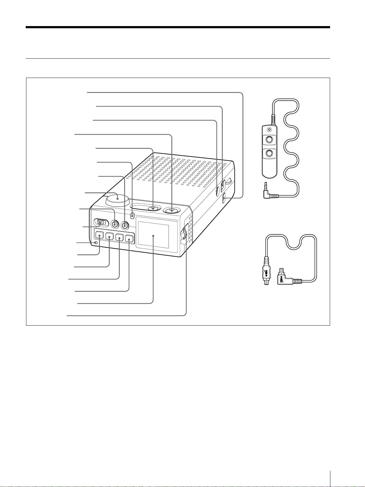
Names and Functions of Parts
DSR-DU1 Video Disk Unit (in Supplied Case)
1 DC IN connector
2 DV IN/OUT connector
3 REMOTE connector
4 CUE button
5 START/STOP button
6 Tally/access indicator
7 LIGHT ON/OFF button
8 Ventilation outlet
9 MENU button
q; POWER switch
qa WARNING
indicator
qs STOP button
qd . button
qf B button
qg > button
qh LCD monitor
qj Jog dial
a DC IN connector
Connect the power supply to the DSR-DU1 from an
AC adaptor or similar.
b DV IN/OUT connector (4-pin, IEEE1394
compliant)
Connect to a camcorder or computer with an
i.LINK cable.
c REMOTE connector
Connect the remote controller supplied with the
unit.
d CUE button
qk Remote controller
ql i.LINK cable
Press this to enter a cue point. You can enter cue
points either during recording or playback, and a
maximum of 400 cue points can be set.
e START/STOP button
This starts or stops recording on this unit.
f Tally/access indicator
The color this lights indicates the state.
Red: During recording
Green: During hard disk access
Orange: During cue point entry
This also flashes to indicate a problem with the
DSR-DU1 (see page 25).
g LIGHT ON/OFF button
Names and Functions of Parts
7
Page 8
This turns the LCD monitor light on or off.
DE
h Ventilation outlet
This is the outlet from the cooling fan.
This is used to operate the menu displayed on the
LCD monitor, and change TC/UB/clip settings.
Turn the dial to select an item, and press to confirm
(see page 23).
Note
Be careful not to obstruct the ventilation opening.
i MENU button
Pressing this button displays the menu in the LCD
monitor (see page 22). Press once more to return to
the DSR-DU1 status display (see next item).
j POWER switch
This powers the DSR-DU1 on or off.
k WARNING indicator
This indicator lights or flashes when there is a
problem with the DSR-DU1 (see page 25).
l STOP button
During playback from the DSR-DU1 hard disk,
pressing this button stops the playback.
m
. (previous) button
During playback, pressing this makes a reverse
search at
×5 speed.
When stopped, pressing this button once moves to
the previous recording start point. Holding down
the button for at least two seconds moves back 10
clips*.
r Remote controller
Connect to the REMOTE connector on the main
unit. This has a START/STOP button, CUE button,
and tally indicator, and the button functions are the
same as those on the main unit. The tally indicator
lights red only during recording.
s i.LINK cable
This cable is supplied with the DSR-DU1, and has
a 4-pin connector at each end. Connect the Lshaped end to the main unit.
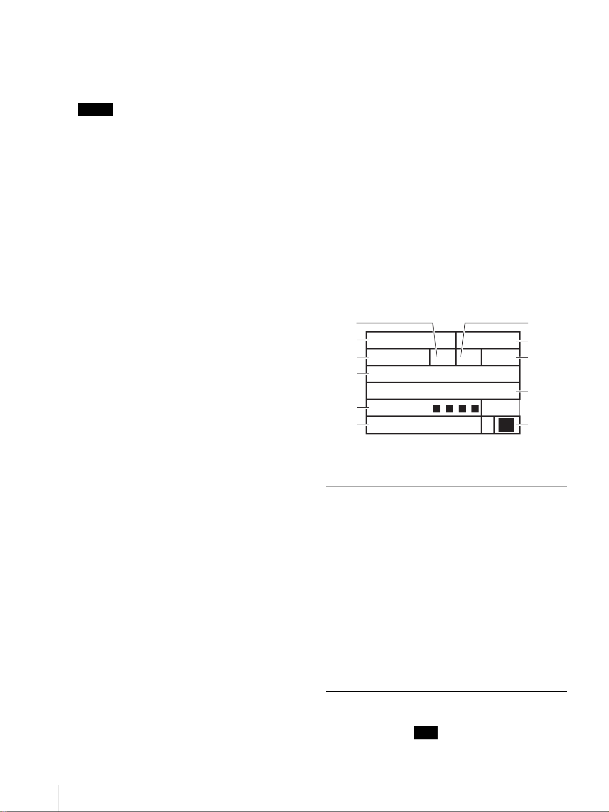
LCD monitor display
When the LCD monitor is not displaying the menu, it
shows the DSR-DU1 status as follows.
A
C
G
I
K
D
YALP
RCT
:HH:MM:SSFF
KSI
XXim
Xn
TTAB
B
F
H
J
iL
*In this system, the term “clip” is used to refer to
the unit of recording from the start point to the end
point.
n
B (playback) button
Display
area
A Command PLAY Playback
This plays back from any position on the DSR-DU1
hard disk.
o
> (next) button
During playback, pressing this makes a forward
search at
×5 speed.
When stopped, pressing this button once moves to
the next recording start point. Holding down the
button for at least two seconds moves forward 10
clips*.
*In this system, the term “clip” is used to refer to
the unit of recording from the start point to the end
point.
This shows the DSR-DU1 status (see next item) or
p LCD monitor
B Recording
a menu (see page 22).
q Jog dial
Type Indication Meaning
P-PAUSE Playback paused
REC Recording
R-PAUSE Recording paused
FWD Search forward
REV Reverse search
STOP Stopped
>> Moving to next
recording start
point
<< Moving to previous
PC-REMOTE Using SBP2
Blank Normal
mode
INT
recording start
point
protocol
Interval recording
8
Names and Functions of Parts
Page 9

Display
Type Indication Meaning
area
C Timecode
type
Clip No. xxxx 4 characters
D Timecode
mode
E Timecode
generator
mode
F Cache
recording
PARA Coupled to
camcorder
Blank When A is “PC-
REMOTE”
DUPLICATE DUPULICATE
mode
TCR Timecode reader
timecode
TCG Timecode
generator timecode
UBR Timecode reader
user bit data
UBG Timecode
generator user bit
data
Blank When A is “PC-
REMOTE”
Blank Drop-frame mode
NDF Non-drop-frame
mode
Blank
EXT Locked to external
timecode
Blank Cache recording
function is off.
Display
Type Indication Meaning
area
I Remaining
main
BATT
[xxxx]
Adequate battery
capacity
battery
capacity
BATT
[xxx ]
BATT
[xx ]
BATT
[x ]
(1 flash/second)
J Remaining
backup
BATT
(4 flashes/second)
Li
(1 flash/second)
Inadequate
capacity to operate
Battery should be
replaced.
battery
capacity
Li
(4 flashes/second)
Since data integrity
cannot be
guaranteed, it is not
possible to write to
the hard disk.
K Alarms MEMORY Shock-proof
memory is full.
i.LINK
(1 flash/second)
When i.LINK input
cannot be detected,
this flashes once
per second. This
does not apply for
i.LINK output.
G Timecode
value
(When C
is TCR or
TCG)
User bit
value
(When C
is UBR or
UBG)
Time from
beginning
of file
(When C
is a file
name)
H Remaining
hard disk
capacity
CACHE Cache recording
function is on.
hh:mm:ss:ff While the jog dial
is pressed, this
shows the
recording time as
hh:mm:ss.
xx yy zz ww While the jog dial
is pressed, this
shows the
recording date
hh:mm:ss While the jog dial
is pressed, this
shows the
recording length of
the file.
--:--:--:-- When A is “PC-
REMOTE”
DISK XXXmin
Names and Functions of Parts
9
Page 10

DSR-DU1 Video Disk Unit (Removed From Supplied Case)
4 Main battery box
To remove the unit from the
case, press down 1, then hold
in 2 while withdrawing the unit
in the direction of the arrow.
3 Backup battery box
Supplied case
2 Release button
1 UNLOCK lever
a UNLOCK lever
To remove the main unit from the supplied case,
first press this lever down.
b Release button
To remove the main unit from the supplied case,
press the UNLOCK lever down, then hold in this
button while removing the unit.
c Backup battery box
Open the lid, and insert the supplied lithium battery
(CR2032). This acts as a backup power supply for
the main unit.
For details of fitting and replacement, see
“Inserting and Replacing the Lithium Battery”
(page 15).
DSR-DU1 main unit
Note
This unit keeps data required to protect the hard
disk data using the backup power supply.
Therefore, when the backup battery capacity is low,
recording is not possible.
d Main battery box
Fit the optional NP-F960/F750 battery pack. This
acts as the main power supply for the DSR-DU1.
To remove the battery pack, hold down the PUSH
button on the side of the box.
For details of fitting, see “Fitting the battery “
(page 17).
10
Names and Functions of Parts
Page 11

CA-DU1 Camera Adaptor (option)
Battery pack connection interface.
4-pin
Camcorder connection interface
5Cable holder
4 i.LINK cable
6-pin
1 DC IN connectorr
a DC IN connector
Connect the power supply from an AC adaptor or
similar.
b REMOTE connector
Connect the remote controller supplied with the
DSR-DU1.
c DV IN/OUT connector (4-pin)
Connect to the camcorder using the i.LINK cable
(4-pin
– 6-pin) supplied with the camera adaptor.
d i.LINK cable (4-pin
– 6-pin)
Connect the 4-pin connector to the camera adaptor,
and the 6-pin connector to the camcorder.
3 DV IN/OUT connector
2 REMOTE connector
With i.LINK cable attached
e Cable holder
Use this when connecting the camera adaptor and
camcorder with an i.LINK cable.
Names and Functions of Parts
11
Page 12

Example System Configurations
Connecting to a Camcorder With an i.LINK Cable
As an example, the following illustrates connection to a
DSR-PD150/PD150P Digital Camcorder.
1
Leave the DSR-DU1 main unit in the supplied case.
2
With the i.LINK cable (4-pin - 4-pin) supplied with
the DSR-DU1, connect together the DV IN/OUT
connectors of the DSR-DU1 and the camcorder.
DSR-PD150/PD150P or
DSR-PD100A/PD100AP
Digital Camcorder
The L-shaped end of the i.LINK cable connects to
the DSR-DU1.
3
Provide the power supply by any of the following
methods.
• Install a battery pack (NP-F960/F750).
• Connect an AC adaptor to the DSR-DU1 DC IN
connector.
DSR-DU1 Video Disk Unit
with Supplied Case
NP-F960/F750 Battery Pack
4-pin(L-shaped)
4-pin
i.LINK cable (supplied with DSR-DU1)
12
Example System Configurations
Page 13

Connecting to a Camcorder Through the CA-DU1 Camera Adaptor
As an example, the following illustrates connection to a
DSR-370/370P/570WS/570WSP Digital Camcorder.
1
Remove the DSR-DU1 main unit from the supplied
case.
2
Attach the CA-DU1 Camera Adaptor to the
camcorder.
3
With the i.LINK cable supplied with the camera
adaptor, connect the 6-pin connector to the DV
OUT connector of the camcorder, and the 4-pin
connector to the DV IN/OUT connector of the
camera adaptor.
DSR-DU1 Video Disk Unit
4
Insert the DSR-DU1 main unit in the camera
adaptor.
5
Provide the power supply to the camcorder and
DSR-DU1 by any of the following methods.
• Install a battery pack (BP-L90A/L60A/L40A or
BP-M50/M100).
• Connect an AC adaptor to the camera adaptor DC
IN connector.
Note
Whe the DSR-DU1 is connected, do not use the DC
IN connector of the camcorder. This connector does
not supply power to the DSR-DU1.
DSR570WS/570WSP, DSR-370/370P,
or DSR-250/250P Digital Camcorder
6-pin
CA-DU1 Camera
Adaptor
BP-L90A/L60A/L40A or
BP-M50/M100 Battery Pack
4-pin
i.LINK cable (supplied with CA-DU1)
Example System Configurations
13
Page 14

Use As a Source Feeder Supporting the SBP2 Protocol
You can transfer video material recorded on the DSRDU1 as a file in DV format to a nonlinear editing system
or personal computer. The recording start point and end
DSR-DU1 Video Disk Unit
4-pin
Notes
• When using the SBP2 protocol, in menu page 1, set
PC REM to ENA (see page 22).
point are also transferred, for efficient logging on the
computer.
Computer
i.LINK cable
• When using the DSR-DU1 as a source feeder, in menu
page 1 set MODE to STD, and in menu page 3 set
PARAREC to OFF.
Use As a Source Feeder for a Nonlinear Editing System
By connecting to a nonlinear editing system, you can use
the DSR-DU1 as a standalone source feeder for video/
audio signals.
Nonlinear System
Computer
i.LINK (AV/C protocol)
4-pin
DSR-DU1 Video Disk Unit
DSR-DU1 Video Disk Unit
You can also carry out dubbing by connecting a VCR.
Dubbing System
DSR-2000/2000P, DSR1800/1800P, DSR-1500A/
1500AP, or DSR-70A/
70AP Digital Videocasette
Recorder
i.LINK (AV/C
protocol)
4-pin
6-pin
Notes
• When using the AV/C protocol for nonlinear editing,
in menu page 1, set PC REM to DIS (see page 22).
14
Example System Configurations
• When using the DSR-DU1 as a source feeder, in menu
page 1 set MODE to STD, and in menu page 3 set
PARAREC to OFF.
Page 15

Inserting and Replacing the Lithium Battery
This camcorder uses a lithium battery to retain stored
data. When using the camcorder for the first time, be
sure to insert the supplied lithium battery (CR2032). The
camcorder will not operate correctly without this lithium
battery.
3
Take out the lithium battery.
Lifetime of the lithium battery
When the lithium battery’s voltage falls, the lithium
backup battery warning flashes once per second in
the display window. If this warning appears, replace the
lithium battery (CR2032) within three or four days.
The lithium battery has an average service life of about
two years.
Li
Inserting or replacing the lithium battery
Notes
• Carefully read the instructions for inserting and
replacing the lithium battery. Lithium batteries can
explode if misused.
• Use only CR2032 Lithium Batteries. Other types of
lithium batteries may come loose when this camcorder
is moved. If you have difficulty finding CR2032
Lithium Batteries, contact your Sony dealer.
1
Turn the POWER switch on.
2
Press the catch at the top of the battery cover and
open the cover.
Press in and pull up
4
Reverse step 3 to insert a replacement lithium
battery. Make sure that the + symbol on the battery
is facing you.
5
Close the battery cover.
DSR-DU1
(removed from supplied case)
Press and pull up.
Inserting and Replacing the Lithium Battery
15
Page 16

Operation
• When storing the battery out of use for a
considerable period, first charge it fully, then use
it to exhaustion. Then store the battery in a cool
place.
Preparing the Power Supply
Charging the battery
When using an optional InfoLithium* battery (L-series)
as the power supply for the DSR-DU1, use the following
method to charge the battery before use.
* InfoLithium is a trademark of Sony Corporation.
When charging, follow the instructions supplied with
the AC adaptor/charger (option).
To a wa l l
outlet
3
AC-V700A AC
Adaptor/
Charger
(option)
1
Set the mode selector switch to “Charge.”
Note
Charging is not possible if set to Video/Camera.
2
Connect the power cord.
4
4
Display panel
1
1
2
Charging
indicator
Mode selector
switch
Battery
(option)
About the InfoLithium battery
This is a lithium-ion battery, which for supporting
devices notifies its charge state electronically.
The L-series InfoLithium battery are identified by a
mark.
Note
The DSR-DU1 can be used with an InfoLithium battery,
but does not support the communications function for
charging state.
Battery remaining time indication in the AC
adaptor/charger display panel
This indication is provided by data communications
between the AC adaptor and the InfoLithium battery.
Please note that the DSR-DU1 does not have a data
communications capability, so there may be a
discrepancy between the actual battery remaining time
and the indication.
Battery charge state indication
The LCD panel shows an approximate remaining time
for continuous shooting. This may not be an accurate
prediction, depending on the pattern of use.
If the battery indication shows adequate remaining time,
but the power fails immediately, charge the battery to its
fully-charged state. This will correct the indication.
Charging time
Charging times for a completely exhausted battery are as
follows.
16
3
Plug into the wall outlet.
4
Press down the battery and slide in the direction of
the arrow to attach.
Charging starts, and the charging indicator lights.
When charging is completed, all of the segments of
the battery symbol appear in the display panel.
(Normal charging)
The charging indicator goes off, but if you continue
charging until the battery indication “FULL”
appears, the battery capacity will be somewhat
longer. (Full charging)
5
When charging is complete, remove the battery
from the AC adaptor/charger.
Notes
• Do not allow the battery to get wet.
Operation
Battery Time for full charge (Time for normal
charge)
NP-F750 Approx. 170 minutes (110 minutes)
NP-F960 Approx. 245 minutes (185 minutes)
Operating times for continuous recording
Operating times for continuous recording using an NPF960 or NP-F750 InfoLithium battery are as follows.
Battery Operating time from full charge (normal
charge)
NP-F750 Approx. 180 minutes (160 minutes)
NP-F960 Approx. 360 minutes (320 minutes)
Page 17

Fitting the battery
Use the following procedure.
For details, refer to the operating instructions for the
AC adaptor/charger.
Main battery box
2
11
Bottom of DSRDU1 (when in
supplied case)
PUSH button
b mark
1
Insert the battery in the main battery box at the rear
of the main unit.
2
Slide the battery in the direction indicated by the b
mark on the top of the battery.
Removing the battery from the main unit
Hold down the PUSH button at the end of the battery
box, and slide the battery in the opposite direction to that
indicated by the b mark to remove.
Operating from a wall outlet
For prolonged operation, such as playing a tape, you can
operate the unit from a domestic wall outlet, without
worries about battery life.
1
Set the AC adaptor/charger mode selector switch to
“Video/Camera.”
Battery
Menu Settings
Before using the DSR-DU1 for the first time after
purchase, the following menu settings are necessary.
• SYSTEM (525/625 selection) (see page 23)
• DATE PRESET (date and time setting) (see page 23)
Check the other individual items, and if required, change
their settings.
For details, see page 22.
Coupled Recording on the Camcorder Tape and Hard Disk
To record on both the tape and hard disk while coupled
to the camcorder start/stop button, use the following
procedure.
Note
If the DSR-DU1 and the connected camcorder are both
powered on, there may be no i.LINK input from the
camcorder to the DSR-DU1, depending on the
camcorder. In this case, on the LCD monitor of the DSRDU1, “i.LINK” flashes once per second; temporarily
disconnect the i.LINK cable.
In standard mode
1
Power on the DSR-DU1.
2
Make the following menu settings.
Note
When set to “Charge” there is no power supply.
2
Connect the DK cable to the DC IN connector of
the DSR-DU1.
3
Connect the DK cable to the AC adaptor/charger.
4
With the power cord, connect the AC adaptor/
charger to a wall outlet.
Note
You can leave the battery installed while operating from
AC power.
To use the AC adaptor/charger from a vehicle
power supply
Connect the AC adaptor/charger to the vehicle power
supply using an optional car battery cable.
• In page 1 set MODE to STD (see page 22).
• In page 3 set PARAREC to ON (see page 22).
3
Load a tape into the camcorder.
Notes
• If the camcorder is a model DSR-370/370P/
570WS/570WSP, set the camcorder menu item
i.LINK CTL to REC/P or ALL. (For more details
refer to the section of the camcorder operating
instructions describing the settings in the
advanced menu.)
Also set the VTR TRIGGER switch to INT
ONLY.
• If the camcorder is a model DSR-250/250P, set
the camcorder menu item EXT REC CTL to OFF.
(For more details refer to the camcorder operating
instructions.)
Note that even if the camcorder has EXT REC
Operation
17
Page 18

CTL set to ON, you can record on the DSR-DU1
coupled to the camcorder tape operations. To do
this, on the DSR-DU1 set the menu item
PARAREC to OFF.
4
Press the camcorder start/stop button.
Recording starts on the camcorder tape and the hard
disk of the DSR-DU1.
If the cache recording function of the DSR-DU1 is
on, the contents of cache memory are first written
to the hard disk.
5
Press the camcorder start/stop button.
Recording stops on the camcorder tape and the hard
disk of the DSR-DU1.
refer to the section of the camcorder operating
instructions describing the settings in the
advanced menu.)
To couple the operation of the DSR-DU1 to the
camcorder, set the VTR TRIGGER switch to INT
ONLY.
• If the camcorder is a model DSR-250/250P, set
the camcorder menu item EXT REC CTL to OFF.
(For more details refer to the camcorder operating
instructions.)
4
Press the camcorder start/stop button.
Recording starts simultaneously on the camcorder
tape and the hard disk of the DSR-DU1.
5
Press the camcorder start/stop button.
If the tape ends during recording
1
Press the EJECT button on the camcorder.
2
Change the tape.
3
Press the start/stop button on the camcorder.
The DSR-DU1 continues recording while you
change the tape.
Note
In the case of some camcorders such as the DSRPD100A/100AP and DCR-VX2000/VX2000E, if
several minutes elapse with no recording on the
tape (while changing tapes or while recording is
paused), the camcorder powers off.
Depending on the camcorder, when you change
tapes, the sound of the operation may be recorded,
or the i.LINK input to the DSR-DU1 may be
interrupted.
In DUPLICATE mode
In DUPLICATE mode, the hard disk is coupled to the
tape, and records the same audio, video, and timecode as
the tape.
Use the following procedure.
1
Power on the DSR-DU1.
2
In menu page 1, set MODE to DUP (see page 22).
3
Load a tape into the camcorder.
Recording stops simultaneously on the camcorder
tape and the hard disk of the DSR-DU1.
If the tape ends during recording
1
Press the EJECT button on the camcorder.
2
Change the tape.
3
Press the start/stop button on the camcorder.
The DSR-DU1 continues recording while you
change the tape.
Notes
• In the case of some camcorders such as the DSRPD100A/100AP and DCR-VX2000/VX2000E,
if several minutes elapse with no recording on the
tape (while changing tapes or while recording is
paused), the camcorder powers off.
Depending on the camcorder, when you change
tapes, the sound of the operation may be
recorded, or the i.LINK input to the DSR-DU1
may be interrupted.
• The cache recording function does not operate.
• Depending on the camcorder, there may be a
discrepancy of a few frames between the DSRDU1 recording and the tape recording, at the
recording start point and end point.
• The timecode generator counting mode is
automatically set to EXT.
• In DUPLICATE mode, the playback function
does not operate.
18
Notes
• If the camcorder is a model DSR-370/370P/
570WS/570WSP, set the camcorder menu item
i.LINK CTL to REC/P or ALL. (For more details
Operation
Page 19

Recording the Image From the Camcorder to Hard Disk
Note
If the DSR-DU1 and the connected camcorder are both
powered on, there may be no i.LINK input from the
camcorder to the DSR-DU1, depending on the
camcorder. In this case, on the LCD monitor of the DSRDU1, “i.LINK” flashes once per second; temporarily
disconnect the i.LINK cable.
When you press the START/STOP button
on the DSR-DU1
Except when operating coupled to the camcorder start/
stop buttons, it is not necessary to load a tape into the
camcorder. Use the following procedure.
Note
In the factory default setting state of the DCR-VX2000/
VX2000E, if it is operated for several minutes without a
tape loaded, a demonstration function automatically
starts.
To use as a camera without a tape, set this mode to
“OFF.” For details, refer to the Operating Instructions
for the DCR-VX2000/2000E.
Some camcorders may power off if several minutes
elapse with no tape operation.
1
Power on the DSR-DU1.
• Set the DSR-370/370P/570WS/570WSP VTR
TRIGGER switch to EXT ONLY or PARALLEL.
Use the following procedure. (Read this in conjunction
with the operating instructions for the DSR-370/370P/
570WS/570WSP.)
1
Power on the DSR-DU1.
2
Make the following menu settings.
• In page 1 set MODE to STD (see page 22).
• In page 3 set PARAREC to OFF (see page 22).
3
Press the DSR-370/370P/570WS/570WSP start/
stop button.
Recording starts.
4
Press the DSR-370/370P/570WS/570WSP start/
stop button.
Recording stops.
Reviewing Content Immediately After Recording – a Recording Review Operation
When you stop recording, you can automatically play
back the last 15 seconds or so of the recorded material,
or from the beginning of the file if this is shorter.
2
Press the START/STOP button on the DSR-DU1
main unit or remote controller.
This starts recording.
3
Press the START/STOP button on the DSR-DU1
main unit or remote controller once more.
This stops recording.
When you press the DSR-370/370P/
570WS/570WSP start/stop button
If the camcorder is a DSR-370/370P/570WS/570WSP,
even if there is no tape loaded in the camcorder, you can
record on the DSR-DU1 by pressing the camcorder start/
stop button.
Notes
• If the camcorder is a model DSR-370/370P/570WS/
570WSP, set the camcorder menu item i.LINK CTL to
ALL. (For more details refer to the section of the
camcorder operating instructions describing the
settings in the advanced menu.)
Notes
• For the DSR-300A/300AP/500WS/500WSP, a
recording review operation is not possible.
• In the case of the DSR-370/370P/570WS/570WSP,
stop the tape, and set the camcorder VTR TRIGGER
switch to EXT ONLY. In this case, however,
frame-accurate continuous recording on the tape is not
guaranteed.
• For the DSR-PD150/PD150P/PD100A/PD100AP,
DSR-250/250P, and DCR-VX2000/VX2000E, set the
camcorder to VTR mode.
To carry out a recording review operation, press the B
(playback) button.
Notes
• For the i.LINK interface to switch from output to input
takes several seconds. During this interval, no
playback video is output.
• After playback ends, it takes several seconds for the
i.LINK interface to switch from output to input, and
during this interval, no recording is possible.
Operation
19
Page 20

• In DUPLICATE mode, and during interval recording,
the playback function does not operate.
Keeping a Recording of the Last
Few Seconds of Material Before
Pressing the Recording Button –
Cache Recording
When the settings are completed, the “INT”
indication flashes once per second.
2
Press the START/STOP button.
Interval recording starts. During recording, the
indication “ ” appears.
Exiting the interval recording mode
In menu page 1 set MODE to anything other than INT.
INT
Cache recording means that the last few seconds of
video and audio captured by the camcorder are always
held in a cache memory, and are automatically recorded
on the hard disk when the recording button is pressed.
Set the number of seconds of recording held in cache
memory with the CACHE item on menu page 3. (See
page 22.)
Other than this, no operation is required.
Notes
• If the power is turned off during cache recording, the
previous few seconds of video may not be recorded.
• If the interval between a recording pause point and the
next recording start point is less than the set number of
seconds for cache recording, then the cache recording
starts from the recording paused point.
Time-Lapse Recording (or Interval Recording)
This function is convenient for recording observations
of very slow events, such as the opening of a flower. Use
the following procedure.
To carry out normal recording during interval
recording
Press the START/STOP button. You can carry out
normal recording once only. During normal recording,
the “INT” indication flashes once per second, indicating
that an interval recording start is pending.
To end normal recording, press the START/STOP button
once more.
To restart interval recording, press the START/STOP
button once more. The “INT” indication is replaced by
“”.
INT
Notes
• The cache recording time is automatically set to zero.
• The function of coupling to the camcorder is
automatically turned off.
• While the interval recording mode is active, the
playback function does not operate.
Playback
You can check the playback video from the DSR-DU1 in
the camcorder viewfinder or LCD monitor.
1
Make the following menu settings.
• In page 1 set MODE to INT (see page 22).
• In page 4 set INT TIM and INT REC (see
page 22).
INT TIM: Recording interval (select from 30
seconds, 1 minute, 5 minutes, and 10 minutes)
INT REC: Duration of each recording segment
(select from 0.5 seconds, 1 second, 1.5 seconds, 2
seconds)
Example settings:
When INT TIME is set to 10 minutes, and INT
REC to 1 second, the recording is as follows.
1 s
Recording
9 min 59 s
Standby
10 min
1 s
Recording
9 min 59 s
Standby
10 min
• In the case of the DSR-370/370P/570WS/570WSP, set
the camcorder VTR TRIGGER switch to EXT ONLY.
• In the case of the DSR-PD150/PD150P/PD100A/
PD100AP, DSR-250/250P, and DCR-VX2000/
VX2000E, set the camcorder to VTR mode.
To play back
Press the DSR-DU1 B button.
To search at five times normal speed
With the B button of the DSR-DU1 pressed for
playback, hold down the M button to make a forward
search at five times normal speed.
Release the button to return to normal speed playback.
Similarly, hold down the m button to make a reverse
search at five times normal speed.
To jump to a recording start point
With the DSR-DU1 stopped, press the m button to
jump to the immediately previous recording start point.
Hold down the button for at least two seconds to jump
back to the start point 10 files earlier.
20
Operation
Page 21

Press the M button for the same effect in the opposite
direction.
Using the above jump and search operations, you can
rapidly start playback on the DSR-DU1 from any
desired point.
Notes
• For the i.LINK interface to switch from output to input
takes several seconds. During this interval, no
playback video is output.
• After playback ends, it takes several seconds for the
i.LINK interface to switch from output to input, and
during this interval, no recording is possible.
• In DUPLICATE mode, and during interval recording,
the playback function does not operate.
• If the total number of clips has exceeded 750,
playback of consecutive clips may involve a
discontinuity of image or sound or both at joints of
clips (i.e. at recording start points).
Setting Cue Points
On the DSR-DU1, information identifying the recording
start and pause points is automatically recorded to the
hard disk.
By pressing the CUE button during recording/playback,
you can record any point on the hard disk in the form of
cue point information.
With a nonlinear editing system that supports this
information, you can use material recorded on the DSRDU1 for efficient editing.
Deleting Recorded Material (Clips)
To delete the immediately previous recorded
clip
In the menu page 3, select DELETE LAST (see
page 22).
By repeating this operation, you can delete clips from
the hard disk in sequence from the latest.
To delete all clips
In the menu page 5, select DELETE ALL (see page 23).
If the number of clips is large, deleting them may take
several minutes.
Operation
21
Page 22

Page 3 (When MODE is set to STD or INT only)
Menus
Most of the DSR-DU1 settings are carried out in
the menus.
Menu Organization and Content
Page 1
Item Setting and values
(factory default settings shown by an asterisk)
MODE Sets the recording mode.
• STD*: Standard mode
• DUP: Mode in which operation is always
coupled to the tape operation, recording
the same video and timecode values.
The items to be forcibly changed are
displayed.
• INT: Interval recording mode.
The items to be forcibly changed are
displayed.
PC REM Select whether to enable or disable access by
the SBP2 protocol.
•DIS*: Disable
•ENA: Enable
Item Setting and values
DELETE
a)
LAST
PARAREC
(When MODE
is set to STD
only)
CACHE
(When MODE
is set to STD
only)
a) While deleting the last recorded clip, the cache recording function does
not operate. Therefore, after deleting the clip, only the signal input
through the i.LINK interface can be recorded.
(factory default settings shown by an asterisk)
Delete the most recently recorded clip.
A confirmation message appears.
When MODE is set to DUP, it is not possible
to delete the latest file alone.
Switch coupled (parallel) recording with the
camcorder on or off.
•OFF*
•ON
When MODE is set to DUP, this is always ON.
When MODE is set to INT, forcibly set to
OFF.
Set the length of cache recording.
• 0s (0 second)
• 2s (2 seconds)
• 4s (4 seconds)
• 8s (8 seconds)
When MODE is set to DUP, the cache
recording function does not work.
When MODE is set to INT, forcibly set to 0s.
Page 4 (When MODE is set to INT only)
Page 2 (When MODE is set to STD or INT only)
Item Setting and values
TCG Set the timecode advancement mode.
TC PRESET Switch to the screen for setting the timecode
UB PRESET Switch to the screen for setting the user bit
FRAME
(Does not
appear when
SYSTEM is set
to 625.)
(factory default settings shown by an asterisk)
• FREE: Always advancing, in step with the
internal timecode generator.
• REC*: Advancing during recording only,
in step with the internal timecode
generator.
• EXT: Synchronized to the external
timecode generator.
When MODE is set to DUP, this is always
EXT.
preset value. Carry out the operation with the
jog dial.
preset value. Carry out the operation with the
jog dial.
Set the drop-frame mode.
• DF*: Drop-frame
• NDF: Non-drop-frame
Item Setting and values
(factory default settings shown by an asterisk)
INT TIM Set the recording interval.
•0.5m*: 30 seconds
• 1m: 1 minute
• 5m: 5 minutes
• 10m: 10 minutes
INT REC Set the length of each recording.
• 0.5s* (0.5 seconds)
• 1s (1 seconds)
• 1.5s (1.5 seconds)
• 2s (2 seconds)
22
Menus
Page 23

Page 5
Item Setting and values
a)
PB INH
TALLY Select whether or not to disable the recording
DELETE ALL Delete all data from the hard disk.
ENHANCE Select whether or not to display menu pages 6
a) Switching the i.LINK output takes several seconds. To avoid losing a
shooting opportunity because of the delay in switching to recording
after camcorder playback, it is recommended to set this to “ON.” In this
case, the ., B, and > buttons on the DSR-DU1 are disabled.
(factory default settings shown by an asterisk)
Select whether or not to disable operation of
the ., B, and > buttons on the DSRDU1.
• ON: Disable.
•OFF*: Enable.
tally.
•OFF: Disable.
• ON*: Enable.
A confirmation message appears.
and 7 (enhanced menu).
• OFF: Do not display.
• ON: Display.
Page 6
Item Setting and values
(factory default settings shown by an asterisk)
CHECK DISK Check the hard disk for usability.
The meanings of indications showing the
result of CHECK DISK are as follows.
• “DISK: OK”: The hard disk can be used.
• “DISK: NG”: The hard disk cannot be
used.
• “B-PNT: XXX”: A total of “XXX” bad
points (points where recording may not be
performed normally) have been detected.
When the CHECK DISK function ends, select
EXIT.
a) The CHECK DISK function takes about 3.5 hours. To inhibit recording
on all of the detected bad points, it is necessary to carry out the
DELETE ALL operation in menu page 5.
a)
Page 7
Item Setting and values
SYSTEM Video signal format. (Factory default is
DATE PRESET Switch to the screen for setting the date and
(factory defaults are unset)
unset)
• NONE: Unset
• 525U: NTSC. The date format is mm/dd/
yyyy.
• 525J: NTSC. The date format is yyyy/
mm/dd.
• 625: PAL. The date format is dd/mm/
yyyy.
time (hh:mm:ss) preset values. Carry out the
operation with the jog dial.
a)
Making Menu Settings
Use the following procedure.
1
Press the MENU button on the front panel.
The menu appears.
2
Turn the jog dial to select the desired page.
3
Press the jog dial.
It is now possible to select an item.
4
Turn the jog dial to select the desired item, and
press to confirm.
When “TC PRESET,” “UB PRESET” or
“DATE PRESET” item was selected
In the screen for setting the preset value, turn the
jog dial to select the digit in the desired place, and
press to confirm. Next, turn the jog dial to change
the value and press to confirm.
After repeating these operations for all desired
places, select “SET” for preset value confirmation,
or select “EXIT” to cancel.
When the “DELETE LAST” or “DELETE
ALL” item was selected
A confirmation message appears. Select “OK” or
“EXIT.”
Note
The PC REM, DELETE LAST, DELETE ALL, and
SYSTEM settings can only be set either
immediately after powering on the DSR-DU1, or
while it is in stop mode.
5
Turn the jog dial to select the desired setting, and
press to confirm.
When the “MODE” item is changed to
“DUP” or “INT”
A list appears, showing the other items which will
be changed. Select “OK” or “EXIT.”
(After changing from “DUP” or “INT” to “STD,” a
list appears of items which will be changed back to
their settings before selecting DUP or INT.)
a) The sequence for setting the date depends on the selected SYSTEM
setting.
Menus
23
Page 24

When the “PC REMOTE” or “SYSTEM” item
is changed
The LCD monitor shows the following.
The setting is displayed here.
When you selected “OK,” a message “TURN OFF/
ON POWER!!” appears. Power off the DSR-DU1,
then power it on again.
6
To make a setting on a different page, reselect
“PAGE0x” on the top row, then repeat from step 3.
7
To end the menu settings, press the MENU button.
24
Menus
Page 25

LCD and Indicator Error Indications
If a problem should occur in the DSR-DU1, the LCD,
and the WARNING and tally/access indicator show the
problem.
The following table shows the relation between these
:
Constant
: 1 flash/second
: 4 flashes/second
indications and the problem.
LCD indication WARNING
indicator
MEMORY
(constant)
DISK
(1 flash/second)
DISK
(4 flashes/
second)
BATT
(1 flash/second)
BATT
(4 flashes/
second)
Li
(1 flash/second)
Li
(4 flashes/
second) (During
No Input! The i.LINK input has disappeared during recording. Continues
ILL Input! A fault was detected on the i.LINK input during recording. Continues
a)
i.LINK
––
Tally/access
indicator
– • Other than during recording, the hard disk is almost full.
–
–
– Backup battery is almost exhausted. Continues
recording only)
Problem Operation
During recording, the shockproof memory has become full. Continues
• During recording, the hard disk capacity is almost used up.
• During recording, the total number of clips created has
exceeded 750.
• Other than during recording, the total number of clips created
has exceeded 750.
During recording or when recording is paused, the hard disk
capacity is completely used up.
Other than during recording or while recording is paused, the
hard disk is full.
During recording, main battery is almost exhausted. Continues
Other than during recording, the main battery is almost
exhausted.
Main battery is exhausted. Stops
Backup battery is exhausted. Stops, if the
In i.LINK input mode, i.LINK input cannot be detected. Continues
Continues
Continues
Stops
Continues
Continues
operation is
recording.
Continues, if
the operation
is playback.
(but recording
to hard disk
stops)
(but recording
to hard disk
stops)
a) If the DSR-DU1 and the connected camcorder are both powered on,
there may be no i.LINK input from the camcorder to the DSR-DU1,
depending on the camcorder. In this case, on the LCD monitor of the
DSR-DU1, “i.LINK” flashes once per second; temporarily disconnect
the i.LINK cable.
LCD and Indicator Error Indications
25
Page 26

Specifications
DSR-DU1 Video Disk Unit
Power supply voltage
7.2 V DC (using battery)
8.4 V DC (using AC adaptor)
Power consumption
5.6 W
Operating temperature
0 ºC to 40 ºC (32ºF to 104ºF)
Storage temperature
– 20 ºC to +60 ºC (–4ºF to + 140ºF)
Operating humidity
Maximum 85% (no condensation)
Operating altitude
–300 m to +3,000 m (–984 feet to
+9,843 feet)
External dimensions (w/h/d, excluding protrusions)
Approx. 101
× 5
Mass Approx. 500 g (1 lb 1 oz)
Input connectors
DC IN (for power supply input)
Remote (4-pin, mini-jack)
DV IN/OUT (i.LINK interface IEEE
1394 compliant, 4-pin)
Supplied accessories
i.LINK cable (4-pin - 4-pin) (1)
Remote controller (1)
Backup battery (CR2032) (1)
Case (1)
Operation Instruction (1)
CD-ROM manual (1)
Optional accessories
CA-DU1 Camera Adaptor
AC-V700A AC adaptor/charger
NP-F960/F750 Battery Pack
i.LINK cables (4-6-pin):
IL4615A (1.5 m / 5 feet) / IL4635A
(3.5 m / 11 feet)
i.LINK cables (4-4-pin):
IL4415A (1.5 m) / 443N (3.5 m / 11
feet)
× 44 × 142 mm (4 × 1
5
/8 inches)
3
/4
External dimensions (w/h/d, excluding protrusions)
Approx. 101
1
/4 × 5 3/4 inches)
Mass Approx. 400 g (14 oz)
Input connectors
DC IN (XLR 4-pin, male, for power
supply input)
Remote (4-pin, mini-jack)
DV IN/OUT (i.LINK interface IEEE
1394 compliant, 4-pin)
Supplied accessories
i.LINK cable (4-pin - 6-pin) (1)
Operation Guide (1)
Optional accessories
AC-DN1 AC adaptor
BC-L120 AC adaptor/charger
BP-L40/L60A/L90A/M50/M100
Battery Pack
Design and specifications are subject to change without
notice.
× 54.5 × 143 mm (4 × 2
CA-DU1 Camera Adaptor (option)
Power supply voltage
11 to 17 V DC
Operating temperature
0 ºC to 40 ºC (32ºF to 104ºF)
Storage temperature
– 20 ºC to +60 ºC (–4ºF to + 140ºF)
Operating humidity
Maximum 85% (no condensation)
26
Specifications
Page 27

Getting the Best Performance From the Battery
• If the ambient temperature is low, the battery
performance deteriorates, reducing the operating time.
To maximize the operating time, the following
techniques are recommended.
– Keep the battery warm in a pocket, and load it into
the unit immediately before shooting.
• During recording or playback, power off whenever the
unit is not operating.
• Have enough batteries ready to last two or three times
the expected shooting duration, and test shoot with
them before the session.
• The battery is not waterproof. Be careful not to allow
it to get wet.
Indication of remaining battery capacity
If the battery fails even though the indication suggests
there is adequate capacity, fully recharge the battery.
This will correct the remaining capacity indication.
However, if the battery is used for a long time at high
temperature, is left fully charged, or has been very
heavily used, the indication may not be correctly
restored. In this case, use the indication time as a rough
guideline to estimate the remaining capacity.
Battery storage
• If the battery is not used for a long time, to maintain
its performance, it should be fully charged and then
fully discharged with this unit about once a year.
Remove the battery from the unit, and store in a cool
dry place.
• To fully discharge the battery with this unit, leave it
powered on until the battery is exhausted.
Battery lifetime
• The battery has a limited lifetime. As it is repeatedly
used over a long time interval, the capacity gradually
reduces. When the operating time is much less than
the original value, it is time to replace the battery.
• The lifetime varies from one individual battery pack to
another, depending on the pattern of use, and how it
has been stored.
Getting the Best Performance From the Battery
27
Page 28

Sony Corporation
 Loading...