

Page 1

DSR-70A/70AP
3-205-557-61(1)
Digital
Videocassette
Recorder
Operating Instructions
Before operating the unit, please read this manual
thoroughly and retain it for future reference.
Note
The supplied CD-ROM includes Operating Instructions
for the DSR-series Digital Video Cassette Recorder or Player
(English, Japanese, French, German, Italian and Spanish
(DSR-1500A only) versions).
For more details, see “Using the CD-ROM Manual” on page 17.
DSR-70A/70AP
2001 Sony Corporation
Page 2

Owner’s Record
The model and serial numbers are located in the rear.
Record these numbers in the spaces provided below. Refer
to them whenever you call upon your Sony dealer regarding
this product.
Model No.
Serial No.
WARNING
For customers in Europe (DSR-70AP only)
This product with the CE marking complies with the EMC
Directive (89/336/EEC) issued by the Commission of the
European Community.
Compliance with this directive implies conformity to the
following European standards:
• EN55103-1: Electromagnetic Interference (Emission)
• EN55103-2: Electromagnetic Susceptibility (Immunity)
This product is intended for use in the following
Electromagnetic Environment(s):
E1 (residential), E2 (commercial and light industrial), E3
(urban outdoors) and E4 (controlled EMC environment, ex.
TV studio).
To prevent fire or shock hazard, do not
expose the unit to rain or moisture.
To avoid electrical shock, do not open
the cabinet. Refer servicing to qualified
personnel only.
For customers in the U.S.A (DSR-70A only)
This equipment has been tested and found to comply with the
limits for a Class A digital device, pursuant to Part 15 of the
FCC Rules. These limits are designed to provide reasonable
protection against harmful interference when the equipment
is operated in a commercial environment. This equipment
generates, uses, and can radiate radio frequency energy
and, if not installed and used in accordance with the
instruction manual, may cause harmful interference to radio
communications. Operation of this equipment in a residential
area is likely to cause harmful interference in which case the
user will be required to correct the interference at his own
expense.
You are cautioned that any changes or modifications not
expressly approved in this manual could void your authority
to operate this equipment.
The shielded interface cable recommended in this manual
must be used with this equipment in order to comply with the
limits for a digital device pursuant to Subpart B of Part 15 of
FCC Rules.
Caution
Television prograrms, films, video tapes and other materials
may be copyrighted.
Unauthorized recording of such material may be contrary to
the provisions of the copyright laws.
For customers in the USA and Canada
RECYCLING LITHIUM-ION BATTERIES
You can help preserve our environment by returning your
used rechargeable batteries to the collection and recycling
location nearest you.
For more information regarding recycling of rechargeable
batteries, call toll free 1-800-822-8837, or visit http://www/
rbrc.org/.
Caution: Do not handle damaged or leaking Lithium-Ion
batteries.
RECYCLING NICKEL-CADMIUM BATTERIES
You can help preserve our environment by returning your
used rechargeable batteries to the collection and recycling
location nearest you.
Note: In some areas the disposal of Nickel-Cadmium
batteries in household or business trash may be
prohibited.
For more information regarding recycling of rechargeable
batteries, call toll free 1-800-822-8837, or visit http://www/
rbrc.org/.
Caution: Do not handle damaged or leaking Nickel-Cadmium
batteries.
2
Page 3

Voor de Klanten in Nederland
• Dit apparaat bevat een vast ingebouwde batterij die niet
vervangen hoeft te worden tijdens de levensduur van het
apparaat.
• Raadpleeg uw leverancier indien de batterij toch vervangen
moet worden.
De batterij mag alleen vervangen worden door
vakbekwaam servicepersoneel.
• Gooi de batterij niet weg maar lever deze in als klein
chemisch afval (KCA).
• Lever het apparaat aan het einde van de levensduur in voor
recycling, de batterij zal dan op correcte wijze verwerkt
worden.
AVERTISSEMENT
Afin d’éviter tout risque d’incendie ou d’électrocution, ne pas
exposer l’appareil à la pluie ou à l’humidité.
Afin d’écarter tout risque d’électrocution, garder le coffret
fermé. Ne confier l’entretien de l’appareil qu’à un personnel
qualifié
Attention
Des programmes de télévision, films, bandes vidéo et autres
peuvent être protégés par des droits d’auteur.
L’enregistrement non autorisé de tels matériaux risque de
constituer une violation de ces droits d’auteur.
Pour les clients européens
(DSR-70AP uniquement)
Ce produit portant la marque CE est conforme à la Directive
sur la compatibilité électromagnétique (EMC) (89/336/CEE)
émise par la Commission de la Communauté européenne.
La conformité à cette directive implique la conformité aux
normes européennes suivantes:
• EN55103-1: Interférences électromagnétiques (émission)
• EN55103-2: Sensibilité électromagnétique (immunité)
Ce produit est prévu pour être utilisé dans les
environnements électromagnétiques suivants:
E1 (résidentiel), E2 (commercial et industrie légère), E3
(urbain extérieur) et E4 (environnement EMC contrôlé ex.
studio de télévision).
Pour les utilisateurs aux Etats-Unis et au Canada
RECYCLAGE DES ACCUMULATEURS AUX IONS DE
LITHIUM
Les accumulateurs aux ions de lithium sont recyclables.
Vous pouvez contribuer à préserver l’environnement en
rapportant les piles usées dans un point de collection et
recyclage le plus proche.
Pour plus d’informations sur le recyclage des accumulateurs,
téléphonez le numéro 1-800-822-8837 (Etats-Unis et
Canada uniquement), ou visitez http://www.rbrc.org/.
Avertissement: Ne pas utiliser des accumulateurs aux ions
de lithium qui sont endommagés ou qui fuient.
3
Page 4

RECYCLAGE DES PILES AU NICKEL-CADMIUM
VORSICHT
Um Feuergefahr und die Gefahr eines elektrischen Schlages
zu vermeiden, darf das Gerät weder Regen noch
Feuchtigkeit ausgesetzt werden.
Les piles au nickel-cadmium sont recyclables.
Vous pouvez contribuer à préserver l’environnement en
rapportant les piles usées dans un point de collection et
recyclage le plus proche.
Remarque: Dans certains pays, il est interdit de jeter les
piles au nickel-cadmium avec les ordures ménagères ou
dans les poubelles de bureau.
Pour plus d’informations sur le recyclage des accumulateurs,
téléphonez le numéro 1-800-822-8837 (Etats-Unis et
Canada uniquement), ou visitez http://www.rbrc.org/.
Avertissement: Ne pas utiliser des piles au nickel-cadmium
qui sont endommagées ou qui fuient.
Um einen elektrischen Schlag zu vermeiden, darf das
Gehäuse nicht geöffnet werden. Überlassen Sie
Wartungsarbeiten stets nur einem Fachmann.
ACHTUNG
Dieses Produkt kann im kommerziellen und in begrenztem
Maße auch im industriellen Bereich eingesetzt werden. Dies
ist eine Einrichtung, welche die Funk-Entstörung nach
Klasse B besitzt.
Für Kunden in Europa
Dieses Produkt besitzt die CE-Kennzeichnung und erfüllt die
EMV-Direktive (89/336/EEC) der EG-Kommission.
Die Erfüllung dieser Direktiven bedeutet Konformität für die
folgenden Europäischen Normen:
• EN55103-1: Elektromagnetische Interferenz (Emission)
• EN55103-2: Elektromagnetische Empfindlichkeit
(Immunität)
Dieses Produkt ist für den Einsatz unter folgenden
elektromagnetischen Bedingungen ausgelegt:
E1 (Wohnbereich), E2 (kommerzieller und in beschränktem
Maße industrieller Bereich), E3 (Stadtbereich im Freien) und
E4 (kontrollierter EMV-Bereich, z.B. Fernsehstudio).
1. Für Ihren privat genutzten Videorecoder muß eine
Fernseh-Rundfunk-Genehmigung beantragt werden,
sofern nicht bereits eine Genehmigung für ein
Fernsehgerät desselben Haushaltes vorliegt. Im
geschäftlichen Bereich ist jeder einzelne Videorecorder
anmelde- und gebührenpflichtig. (Auskunft ggf. bei der
GEZ oder den Rundfunkanstalten.)
2. Im privaten Bereich ist die Aufzeichnung von
urheberrechtlich geschützten Werken auf Bild- und
Tonträger gestattet. Die entsprechenden UrheberVergütungen sind im Kaufpreis des Gerätes enthalten.
Öffentliche Wiedergabe oder Verbreitung von
mitgeschnittenen Fernsehsendungen ist ohne
Erlaubnis nicht zulässig, verpflichtet zu Schadenersatz
und ist gegebenenfalls strafbar.
3. Im Rahmen der Regelung des §47 des
Urheberrechtsgesetzes sind Aufzeichnungen von
Schulfernsehprogrammen gestattet. Mitschnitte von
Schulfunksendungen dürfen jedoch nur für den
Unterricht verwendet werden und sind spätestens am
Ende des laufenden Schuljahres zu löschen.
4
Page 5

ATTENZIONE
Per evitare incendi o scosse elettriche, non esporre
l’apparecchio alla pioggia o all’umidità.
Per evitare scosse elettriche, non aprire l’apparecchio. Per le
riparazioni rivolgersi solo a personale qualificato.
Attenzione
Programmi televisivi, film, videonastri e altro materiale
possono essere tutelati dai diritti d’autore.
Registrazioni non autorizzate di tail materiali possono
infrangere la legge sui diritti d’autore.
Per i clienti in Europa
Questo prodotto recante il marchio CE è conforme alla
direttiva sulla compatibilità elettromagnetica (EMC) (89/336/
CEE) emessa dalla Commissione della Comunità Europea.
La conformità a questa direttiva implica la conformità alle
seguenti normative europee:
• EN55103-1: Interferenza elettromagnetica (Emissione)
• EN55103-2: Sensibilità ai disturbi elettromagnetici
(Immunità)
Questo prodotto è destinato all’uso nei seguenti ambienti
elettromagnetici:
E1 (residenziali), E2 (commerciali e industriali leggeri), E3
(esterni urbani) e E4 (ambienti EMC controllati, ad esempio
studi televisivi).
5
Page 6

Table of Contents
Table of Contents
Chapter 1
Overview
Features............................................................................ 11
Variety of Interfaces..............................................................12
Full Functionality for More Efficient Editing ....................... 12
Other Features .......................................................................13
Options ..................................................................................14
System Configuration ..................................................... 16
Using the CD-ROM Manual ............................................. 17
CD-ROM System Requirements...........................................17
Preparations...........................................................................17
To Read the CD-ROM Manual .............................................17
Location and Function of Parts...................................... 18
Display Panel ........................................................................19
Control Panel.........................................................................21
Front Control Section ............................................................27
Top Panel ..............................................................................28
Rear Panel .............................................................................29
Chapter 2
Power Preparations
Chapter 3
Recording and
Playback
Power Preparations ........................................................ 33
Usable Batteries ................................................................... 33
Using the BP-L60(A)/L90(A) Battery Pack ........................ 34
Using the BP-90(A) Battery Pack ........................................35
Using AC Power ...................................................................36
Handling Cassettes ........................................................ 39
Loading/Ejecting Cassettes ..................................................42
Recording ........................................................................ 44
Preparations for Recording .................................................. 44
Recording Operation ............................................................44
Sequential Recording Using Two Units ...............................45
Parallel Recording Using Two Units .................................... 46
Two-Input Switched Video Recording
(Optional DSBK-180/180P Required) ............................ 48
6 Table of Contents
Digitally Dubbing Signals in DVCAM Format
(Optional DSBK-140/150/160A Required) ..................... 52
Page 7

Chapter 3
Recording and
Playback (Continued)
Chapter 4
Time Data and Sub
LCD Menu
Playback .......................................................................... 57
Preparations for Playback .................................................... 57
Playback Operation ..............................................................58
Two-Unit Synchronous Playback.........................................59
Setting Time Data............................................................ 61
Information Displayed on the LCD Monitor ....................... 61
Setting an Initial Value and Recording Timecode ................63
Synchronizing the Internal Timecode Generator With an
External Signal — External Lock ...................................65
Sub LCD Menu Display and Settings — Making
Operating Mode and Video/Audio Signal Settings ...... 66
Sub LCD Menu Home Page and Sub LCD Operation
Buttons ............................................................................66
Sub LCD Menu Basic Operations........................................68
Input and Output Settings for Video and Audio
Signals — Sub LCD Menu .............................................. 70
Chapter 5
Editing
Making Settings in the Audio Settings Pages ...................... 70
Making Settings in the Audio Settings Subpages ................ 71
Making Settings in the Video Settings Page ........................72
General Settings Pages of the Sub LCD Menu ............ 73
Sequence of Editing Operations ................................... 75
Settings for Editing ........................................................ 76
Recorder Settings .................................................................76
Player Settings......................................................................78
Selecting an Edit Mode .................................................. 79
Assemble Editing .................................................................79
Insert Editing ........................................................................ 79
Finding Edit Points —Search ........................................ 81
Setting Edit Points .......................................................... 82
Setting Edit Points................................................................82
Checking Edit Points............................................................83
(Continued)
Table of Contents 7
Page 8

Table of Contents
Chapter 5
Editing (Continued)
Cuing Up Edit Points ........................................................... 83
Previewing Edit Results .......................................................84
Modifying Edit Points ..........................................................85
Setting Edit Points Using the Recorder Only.......................85
Executing an Edit ........................................................... 86
Outline of Editing Operations ..............................................86
Starting an Edit.....................................................................86
Redoing an Edit....................................................................87
DMC Editing .................................................................... 89
Overview of DMC Editing...................................................89
Setting Edit Points and Playback Speeds .............................90
Executing DMC editing .......................................................91
Special Editing ................................................................ 92
Quick Editing .......................................................................92
Continuous Editing ..............................................................93
Manual Editing.....................................................................94
Chapter 6
ClipLink Operation
Overview of ClipLink Operation .................................... 95
Displaying ClipLink Log Data ........................................ 96
Detailed Data Display ..........................................................96
Cuing Up to Mark IN/OUT and Cue Points.................... 97
Cuing Up to Any Desired Position....................................... 97
Cuing Up to Adjacent Mark IN/Cue Points ......................... 97
Rewriting ClipLink Log Data.......................................... 98
Changing the Reel Number .................................................. 98
Changing Mark IN/OUT Points ...........................................98
Changing the OK/NG Status ................................................ 99
Adding to/Deleting From ClipLink Log Data .............. 101
Adding Mark IN/OUT Points ............................................101
Deleting Mark IN/OUT Points...........................................101
Automatically Creating New ClipLink Log Data ........ 103
8 Table of Contents
Page 9

Chapter 7
Setup Menu
Chapter 8
Connections and
Settings
Menu System Configuration ........................................ 105
Basic Menu .................................................................... 105
Items in the Basic Menu.....................................................105
Basic Menu Operations ......................................................108
Extended Menu ............................................................. 111
Items in the Extended Menu .............................................. 111
Extended Menu Operations................................................119
Reference Video Signals for Analog Signal
Editing ........................................................................... 121
Connections for Cut Editing Using Two
DSR-70A/70AP Units — i.LINK Connections
(Optional DSBK-140/160A Required) .......................... 122
Connections for Digital Nonlinear Editing Using SDTI
(QSDI) Interface (Optional DSBK-150 Required) ....... 123
Connections for Cut Editing Using SDI Interface
(Optional DSBK-160A Required) ................................. 124
Settings Required When Connecting an External
Editing Control Unit ...................................................... 124
Timecode Settings on This Unit.........................................124
Settings on Editing Control Units ......................................125
Connections for Component Analog Recording
(Optional DSBK-170 Required) .................................... 126
Connections for Sequential Recording Using Two
Units ............................................................................... 127
Connections for Parallel Recording Using Two
Units ............................................................................... 129
Connections for Two-Unit Synchronous Playback .... 131
Connections for Two-Input Switched Video Recording
(Optional DSBK-180/180P Required) .......................... 132
Connections for Digitally Dubbing Signals in DVCAM
Format (Optional DSBK-140/150/160A Required) ...... 133
Combining Two VCRs ................................................... 134
Using the Shoulder Belt ............................................... 135
Table of Contents 9
Page 10

Table of Contents
Chapter 9
Maintenance and
Troubleshooting
Appendixes
Condensation................................................................ 137
Head Cleaning............................................................... 137
Periodic Maintenance................................................... 138
Troubleshooting............................................................ 139
Error Messages...................................................................141
Alarm Messages .................................................................141
Specifications ............................................................... 145
TM
ClipLink
What Is ClipLink? ..............................................................149
Example System Configuration and Operation Flow ........150
Data Generated When Shooting.........................................151
Glossary ........................................................................ 154
Index .............................................................................. 157
Guide ........................................................... 149
10 Table of Contents
Page 11

Features
Chapter1
Chapter 1 Overview
Overview
The DSR-70A/70AP is a 1/4-inch digital videocassette
recorder using the DVCAM
It uses a component video system, with separate
luminance and chrominance signals and digital
processing to realize a stable, high image quality.
This unit is lightweight and compact, with a color
liquid crystal display and speakers, making it easy to
carry, yet ideal for on-the-spot checking of recorded
material.
By combining two units, you can easily assemble a cut
editing system.
The unit supports the Sony-developed ClipLink
function, improving operating efficiency when
combined with a Sony EditStation
A range of optional interface boards is available, with
support for both digital and analog systems.
The following are the principal features of the unit.
TM
digital recording format.
TM
TM
.
DVCAM Format
DVCAM is a professional 1/4-inch digital recording
format developed by Sony from the DV 4:1:1
component digital format for home use.
High image quality and high stability
The luminance and chrominance signals are encoded
separately, with a
quality video image.
Since this is a digital system, nth-generation copies
created by repeated dubbing show virtually no loss in
picture quality.
1
/5 compression, giving a stable high
Wide track
The recording track width is 15 µm, 50% wider than
the 10 µm of the DV format. This ensures adequate
reliability for professional use.
PCM digital audio for high sound quality
The PCM encoding method yields a high audio
quality, with wide dynamic range and high signal-tonoise ratio.
There are two recording modes: two-channel mode
(48-kHz sampling and 16-bit quantization), which
offers sound quality equivalent to the DAT (Digital
Audio Tape) format, or four-channel (32-kHz
sampling and 12-bit quantization).
Chapter 1 Overview 11
Page 12

Location and Function of Parts
Features
Playback compatibility with DV and
DVCPRO formats
A DV cassette recorded on a DV format VCR as well
Chapter 1 Overview
as a DVCPRO (25M) format recorded cassette can be
played back on this unit.
Note
When playing back a tape recorded in DVCPRO
(25M) format, the SDTI and i.LINK outputs (see the
section “Digital interfaces” on this page) of this unit
are muted. Furthermore, it is not possible to playback
the cue-audio track of the tape.
Support for three cassette sizes
There are two sizes of DVCAM cassette: standard and
mini. You can use either size with this unit.
The unit also accepts L and M sizes of DVCPRO
(25M) cassette.
• The reel mechanism automatically adjusts to the size
of cassette inserted.
• The capacity of a standard cassette is 184 minutes of
recording/playback, and that of a mini cassette is 40
minutes.
2)
• SDI
This interface allows the unit to input or output D1
(component) digital video and audio signals.
(Optional DSBK-160A board)
• i.LINK (DV)
3)
The DV input/output connector using i.LINK
technology allows the unit to input and output digital
video and audio signals in DV format. (Optional
DSBK-140/160A board)
Analog interfaces
A wide range of analog interfaces is provided,
allowing this unit to be connected to various video and
audio devices.
• Analog video: Composite and S-video interfaces are
provided. There is also a component interface option
(DSBK-170).
• Analog audio: There are two input channels and two
output channels. There is also support for microphone
input.
Full Functionality for More Efficient Editing
This unit has functions which assist in efficient and
Variety of Interfaces
precise editing.
With two DSR-70A/70AP units together, you can
carry out automatic or manual editing, using either
Digital interfaces (options)
assemble or insert editing.
The system also provides a powerful range of
The unit can use the following digital interfaces
provided by optional interface boards (see page 14).
• SDTI (QSDI)
1)
This interface allows video, audio and timecode
signals in SDTI (QSDI) format to be transferred at
normal speed between this unit and the ES-7
EditStation. When this unit is connected to another
functions for setting and amending edit points,
preview, review, and other aspects of efficient editing.
DMC (dynamic motion control) editing
1
You can save a varying speed, in the range –
/2 to +1/2
times normal speed, for an editing segment, and
automatically edit with this varying speed.
DVCAM VCR, it is possible to copy compressed
signals between the two VCRs. (Optional DSBK-150
board)
.........................................................................................................................................................................................
1) SDTI (QSDI): SDTI (Serial Data Transport Interface) is
the name of a standard interface established as SMPTE
305M.
This unit uses SDTI to transmit DV data, and the input/
output connectors are labled “SDTI(QSDI).”
In indicator and menu indications, however, the
“SDTI(QSDI)” name is shortened to “SDTI.”
2) SDI: Serial Digital Interface is used for transferring video
signals in component digital format (D1).
3) is a trademark of Sony Corporation and indicates that
this product is in agreement with IEEE1394-1995
specifications and their revisions.
12 Chapter 1 Overview
Page 13

Split editing
In insert editing, this allows the audio IN point to be
set separately from the video IN and OUT points.
Support for ClipLink function
This unit accepts instructions from an EditStation, to
transfer to the EditStation ClipLink log data held in the
cassette memory or index pictures recorded on the
tape. On the EditStation you can use these images and
data to carry out editing operations efficiently.
• Displaying ClipLink log data
• Changing ClipLink log data OK/NG status
• Cuing up to Mark IN and cue points provided by
ClipLink log data
• For cut editing, copying Mark IN data from ClipLink
log data
Digital slow motion playback
Using the frame memory function, noiseless slow
motion playback is possible at any speed in the range
1
/2 to –1/2 times normal speed.
+
Digital jog sound function
When searching at speeds in the range +1 to +1/30 or
1
/30 to –1 times normal speed, the digital jog sound
–
function is enabled. The audio signal is saved in
temporary memory, and replayed according to the
search speed. This allows searching on the sound
track.
Video process control
Chapter 1 Overview
For an overview of the ClipLink function, see the appendix
“ClipLink Guide” (page 149).
Internal timecode generator and reader
An internal timecode generator and reader enables
timecode compliant with SMPTE/EBU format to be
recorded and played back. This allows editing to single
frame precision.
Outputting or inputting timecode (LTC) to or from an
external device is also possible using the TIME CODE
IN/OUT connectors.
The unit is also compatible with VITC.
High-speed search function
You can carry out a picture search while playing back
in color within the range +32 to –32 times normal
1)
speed
When controlling the unit in shuttle mode from an
editor or remote control unit, you can search at any
speed in the range +32 to –32 times normal speed. In
jog mode a frame by frame search is possible. During
playback in the range +10 to –10 times normal speed,
high-speed audio playback is also possible.
.
For analog video output and SDI-format video output,
you can adjust the video output level, chroma signal
output level, setup level (for DSR-70A), black level
(for DSR-70AP), and chroma phase.
Other Features
Two-Input video recording
With the optional DSBK-180/180P Dual Video Input
Board installed, you can record, switching between the
composite video input to the VIDEO INPUT connector
and the composite video input to the REF. VIDEO IN
connector.
The ease of switching video inputs when recording
helps improve later editing efficiency.
Menu operations for functions and
operating settings
To make it easier to use this unit for any particular
purpose, various functions and operating settings are
provided in the menu system.
.........................................................................................................................................................................................
1) The positive direction refers to forward movement of the
tape, and the negative direction to reverse movement.
Chapter 1 Overview 13
Page 14

Location and Function of Parts
Features
Superimposing function
Timecode, operating mode, error messages, and other
text information, can be superimposed on the color
Chapter 1 Overview
liquid crystal display and the analog composite video
signal output.
Functions for easy maintenance
• Self-diagnosis and alarm function: This
automatically detects incorrect operations or
connections, operating faults, and so forth, and
displays details of the problem, the cause, and the
action to be taken, in the color liquid crystal display
and the time data display.
• Digital hours meter: This keeps four cumulative
counts of the powered on time, the drum rotation
time, the tape transport time, and the number of tape
threadings and unthreadings, and displays them in the
color liquid crystal display and the time data display.
Sequential recording
AC and DC power
This unit is equipped with V-shoe attachment, on
which BP-L60/L60A/L90/L90A or BP-90/90A battery
or an AC adaptor can be mounted. The unit can
operate for about 120 minutes (with no optional boards
installed) with BP-L90 battery mounted. For AC
operation, you can connect an AC-550/550CE or ACDN2A/DN2B adaptor.
Combination of two units
Using the optional BKNW-225 Docking Kit to
combine two DSR-70A/70AP units gives you a
portable editor.
Compact and lightweight
Even though it is equipped with an LCD monitor and a
speaker, the unit weighs only 5.8 kg (12 lb 12 oz). Its
compact design makes it easy to carry anywhere.
Combining two DSR-70A/70AP units allows you to
perform sequential recording from one unit to another.
Using two cassettes repeatedly, the last six hours of
recording is always available (using 184 minute tapes).
When you renew the cassette about every 3 hours,
endless recording is possible.
Compatible with wide screen aspect ratio
(16:9)
The unit can record and play back aspect ratio
information. When video accompanied by wide-screen
aspect ratio information is recorded or played back, the
unit’s LCD monitor automatically switches to 16:9
mode. The video signal output from the unit also
contains the aspect ratio information.
Options
Optional boards
The optional boards available are as follows.
You can use any and only one of the following boards
at the same time.
• DSBK-140 i.LINK/DV Input/Output Board
This board enables cut editing between two DSR70A/70AP units. This board also allows you to
connect the unit to other equipment provided with a
Sony DV connector to carry out editing or dubbing
of digital video and audio signals.
• DSBK-150 SDTI (QSDI) Input/Output Board
The unit fitted with this board can be connected to
the ES-7 EditStation to carry out digital nonlinear
editing. You can also connect the unit to the DSR-85/
85P/80/80P/60/60P Digital Videocassete Recorder or
Player and carry out digital editing or dubbing
operation.
14 Chapter 1 Overview
Page 15

• DSBK-160A SDI/i.LINK/DV Input/Output Board
Using this board, you can connect the unit to the
DNW-A25/A25P Betacam SX Digital Videocassette
Recorder and carry out cut editing. This unit
additionally has the function of the DSBK-140 board.
• DSBK-170 Analog Component Input/Output
Board
This board allows you to connect the unit to Betacam
SP VCRs and carry out editing and dubbing
operations.
The following board may be used in combination with
any one of the above four boards.
• DSBK-180/180P Dual Video Input Board
This board allows two video cameras to be connected
to the unit so that you may carry out video recording
switching between the signals from the two cameras.
BKNW-225 Docking Kit
Use to combine two DSR-70A/70AP units.
Chapter 1 Overview
Chapter 1 Overview 15
Page 16
Location and Function of Parts
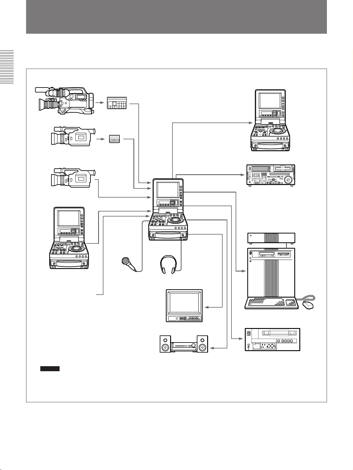
System Configuration
The figure below shows example equipment that can
be connected to this unit.
Chapter 1 Overview
DVCAM camcorder
DV camcorder
DV camcorder
DSR-70A/70AP
DVCAM cassette
DV cassette
i.LINK
(DSBK-140/160A)
i.LINK
(DSBK-140/160A)
Microphone
a)
a)
DSR-70A/70AP
(This unit)
b)
Headphones
SDI(DSBK-160A)
SDTI(QSDI)
(DSBK-150)
SDTI(QSDI)
(DSBK-150)
Component
(DSBK-170)
a)
a)
DNW-A25/A25P digital VCR
a)
a)
DSR-85/85P/1500/1500P/1600/
1600P/1800/1800P/2000/2000P
digital VCR
Battery packs,
AC adaptors
a) The DSBK-140/150/160A/170 is an optional board.
b) Caution
Using a microphone other than a 48-V microphone
may damage the microphone.
16 Chapter 1 Overview
Video monitor
Audio monitor System
ES-7 EditStation
Analog Betacam VCR
Page 17

Using the CD-ROM Manual
The supplied CD-ROM includes Operating
Instructions for the DSR-series Digital Video Cassette
Recorder or Player (English, Japanese, French,
German, Italian and Spanish (DSR-1500A only)
versions).
CD-ROM System Requirements
The following are required to access the supplied CDROM disc.
• Computer: PC with MMX Pentium 166 MHz or
faster CPU, or Macintosh computer with PowerPC
CPU.
– Installed memory: 32 MB or more
– CD-ROM drive: × 8 or faster
• Monitor: Monitor supporting resolution of 800 × 600
or higher
When these requirements are not met, access to the
CD-ROM disc may be slow, or not possible at all.
Preparations
To Read the CD-ROM Manual
To read the Operating Instructions contained in the
CD-ROM disc, do the following.
Chapter 1 Overview
1 Insert the CD-ROM disc in your CD-ROM drive.
A cover page appears automatically in your
browser.
If it does not appear automatically in the browser,
double click the index.htm file on the CD-ROM
disc.
2 Select and click the Operating Instructions that you
want to read.
A PDF file of the Operating Instructions opens.
Note
If you lose the CD-ROM disc or become unable to
read its content, for example because of a hardware
failure, contact a Sony service representative.
The following software must be installed on your
computer in order to use the Operating Instructions
contained in the CD-ROM disc.
• Microsoft Internet Explorer Version 4.0 or higher, or
Netscape Navigator Version 4.0 or higher
• Adobe Acrobat Reader Version 4.0 or higher
Notes
• If Microsoft Internet Explorer is not installed, it may
be downloaded from the following URL:
http://www.microsoft.com/ie
• If Netscape Navigator is not installed, it may be
downloaded from the following URL:
http://home.netscape.com/
• If Adobe Acrobat Reader is not installed, it may be
downloaded from the following URL:
http://www.adobe.com/products/acrobat/
readstep.html
.........................................................................................................................................................................................
• MMX and Pentium are registered trademarks of Intel
Corporation or its subsidiaries in the United States and
other countries.
• PowerPC is a registered trademark of International
Business Machines Corporation.
• Macintosh is a registered trademark of Apple Computer,
Inc.
• Microsoft is a registered trademark of Microsoft
Corporation in the United States and/or other countries.
• Netscape Navigator is a registered trademark of Netscape
Communications Corporation in the U.S. and other
countries.
• Adobe and Acrobat are registered trademarks of Adobe
Systems Incorporated in the United States and/or other
countries.
Chapter 1 Overview 17
Page 18
Location and Function of Parts
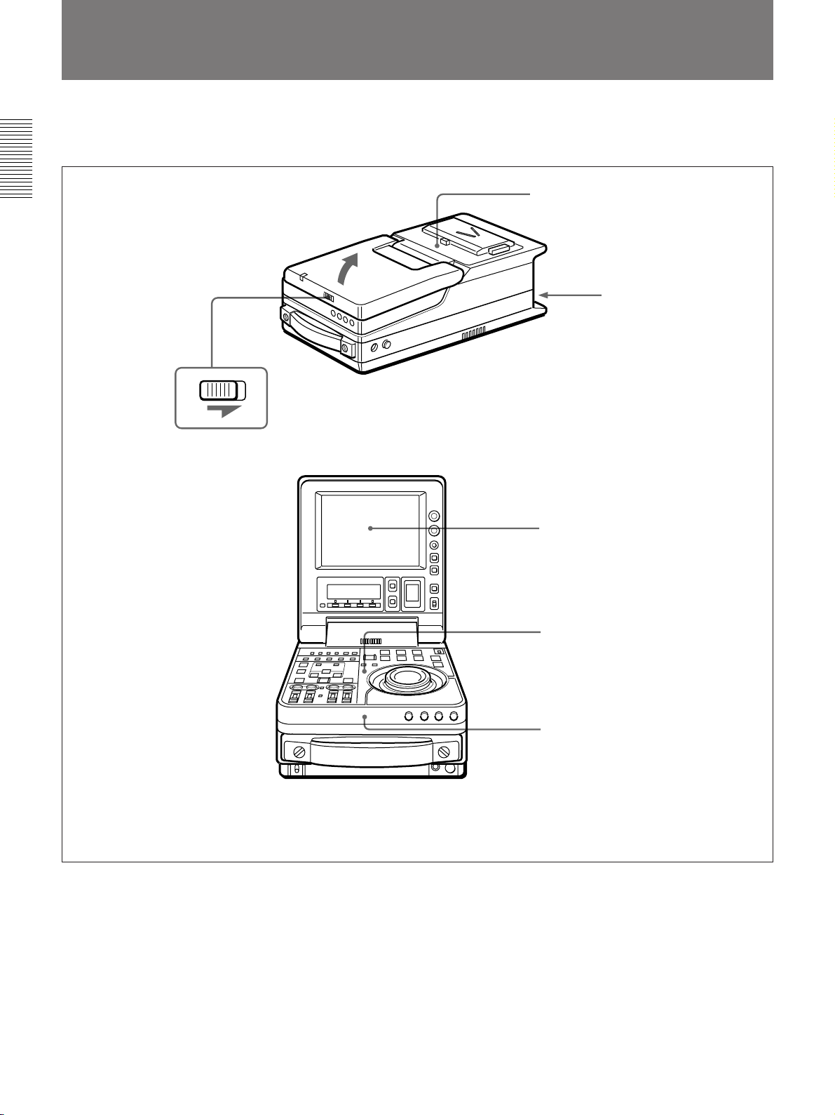
Location and Function of Parts
This unit is comprised of the parts shown in the figure
below.
Chapter 1 Overview
Top panel (see page 27)
Rear panel (see page 28)
Slide the lock release switch and pick up
the display panel.
How to open the display panel
Display panel (see page 18)
Control panel (see page 20)
Front control section
(see page 26)
18 Chapter 1 Overview
Page 19
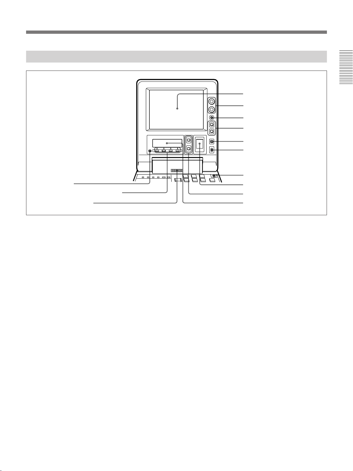
Display Panel
qd PAGE button
qs Sub LCD operation buttons F1 to F4
qa Audio monitor speaker
Chapter 1 Overview
1 LCD monitor
2 BRIGHT/CONTRAST knob
3 WARNING indicator
4 Timecode operation buttons
5 COUNTER SELECT button
6 LIGHT switch
7 METER switch
8 Audio level meter
9 UP and DOWN buttons
q; Sub LCD
1 LCD monitor
1)
Displays the playback or E-E pictures
. Time data,
status information, and setup menus, etc. are
superimposed on the LCD monitor.
2 BRIGHT (brightness)/CONTRAST knob
Adjusts the brightness and contrast of the LCD
monitor 1. Adjustments have no effect on the
recorded or output video.
3 WARNING indicator
Lights when the battery is exhausted or an error
occurs.
It flashes when the end of battery power is near.
4 Timecode operation buttons
HOLD button: Stops the progress of the timecode
generator. Press this button before setting
timecode or user bits to hold those values.
RESET button: Press this to reset the preset data of
CNT (counter value) or TC (timecode) or UB
(user bit) indication in the sub LCD q;. Resetting
the CNT value erases all edit points that have been
set.
Use this button also when resetting the setup menu
to its factory default settings.
For more information, see “Setting Time Data” (page 61).
For information about how to reset the setup menu to its
factory default settings, see “Resetting the menu settings to
their factory default values” (page 109).
5 COUNTER SELECT button
Alternately selects CNT (counter value), TC
(timecode), and UB (user bits) as the time data used in
editing and displayed in the sub LCD q;.
6 LIGHT (backlight on/off) switch
Turns the backlights of the sub LCD q; and audio
level meter 8 on and off.
You can also use the LIGHTSW setting of the sub LCD menu
to turn the LCD monitor power on and off. For details, see
page 74.
7 METER switch
Selects the audio channel whose level is displayed by
the audio level meter 8.
CH-1/2: Display the recording, playback, and E-E
levels of audio channels 1 and 2.
CH-3/4: Display the recording, playback, and E-E
levels of audio channels 3 and 4.
.........................................................................................................................................................................................
1) E-E pictures: “E-E” stands for “Electric to Electric.” In
E-E mode, the video and audio signals that are input to
the VCR’s recording circuitry do not pass through any
magnetic conversion circuits but instead are output via
electric circuits only. The pictures output in E-E mode are
referred to as E-E pictures.
Chapter 1 Overview 19
Page 20

Location and Function of Parts
8 Audio level meter
Displays the recording and playback audio levels of
two (CH-1/2 or CH-3/4) of the four audio channels
(CH-1 to CH-4), as selected with the METER switch
7.
Chapter 1 Overview
9 UP and DOWN buttons
Press to make settings in the sub LCD menu.
For more information about the sub LCD menu, see “Sub
LCD Menu Home Page and Sub LCD Operation Buttons”
(page 66).
q; Sub LCD
Displays time data, status information, remaining
battery capacity, remaining tape time, sub LCD menu,
setup menu and error messages.
For more information about the sub LCD menu, see “Sub
LCD Menu Home Page and Sub LCD Operation Buttons”
(page 66).
qa Audio monitor speaker
Plays the mixed audio signal of the audio channels
selected with the sub LCD menu item MONITOR.
Adjust the volume with the LEVEL knob on the front
control panel. You cannot monitor sound from the
speaker when headphones are connected to the
HEADPHONES jack.
For more information about the MONITOR item, see page
71.
qs Sub LCD operation buttons F1 to F4
Select items in the sub LCD menu.
For more information about the sub LCD menu, see “Sub
LCD Menu Home Page and Sub LCD Operation Buttons”
(page 66).
qd PAGE button
Switches between pages in the sub LCD menu.
For more information about the sub LCD menu, see “Sub
LCD Menu Home Page and Sub LCD Operation Buttons”
(page 66).
20 Chapter 1 Overview
Page 21
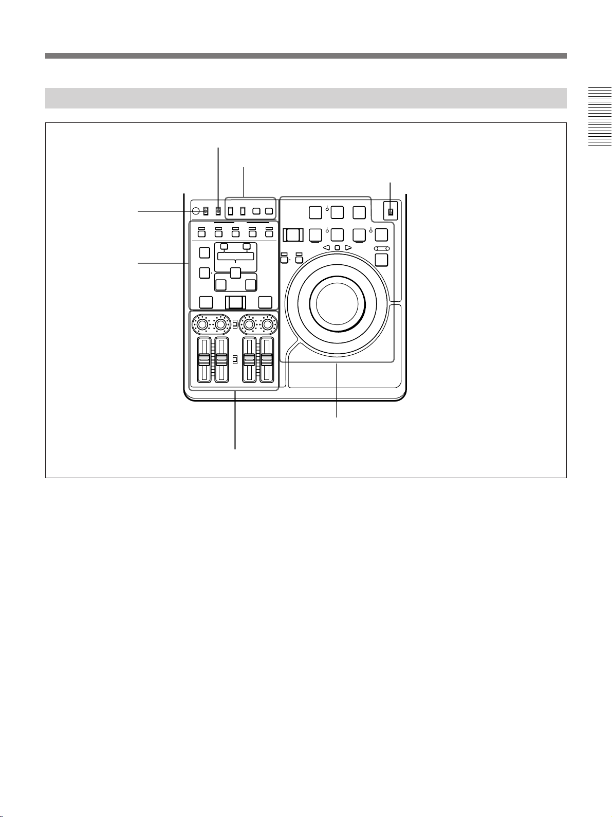
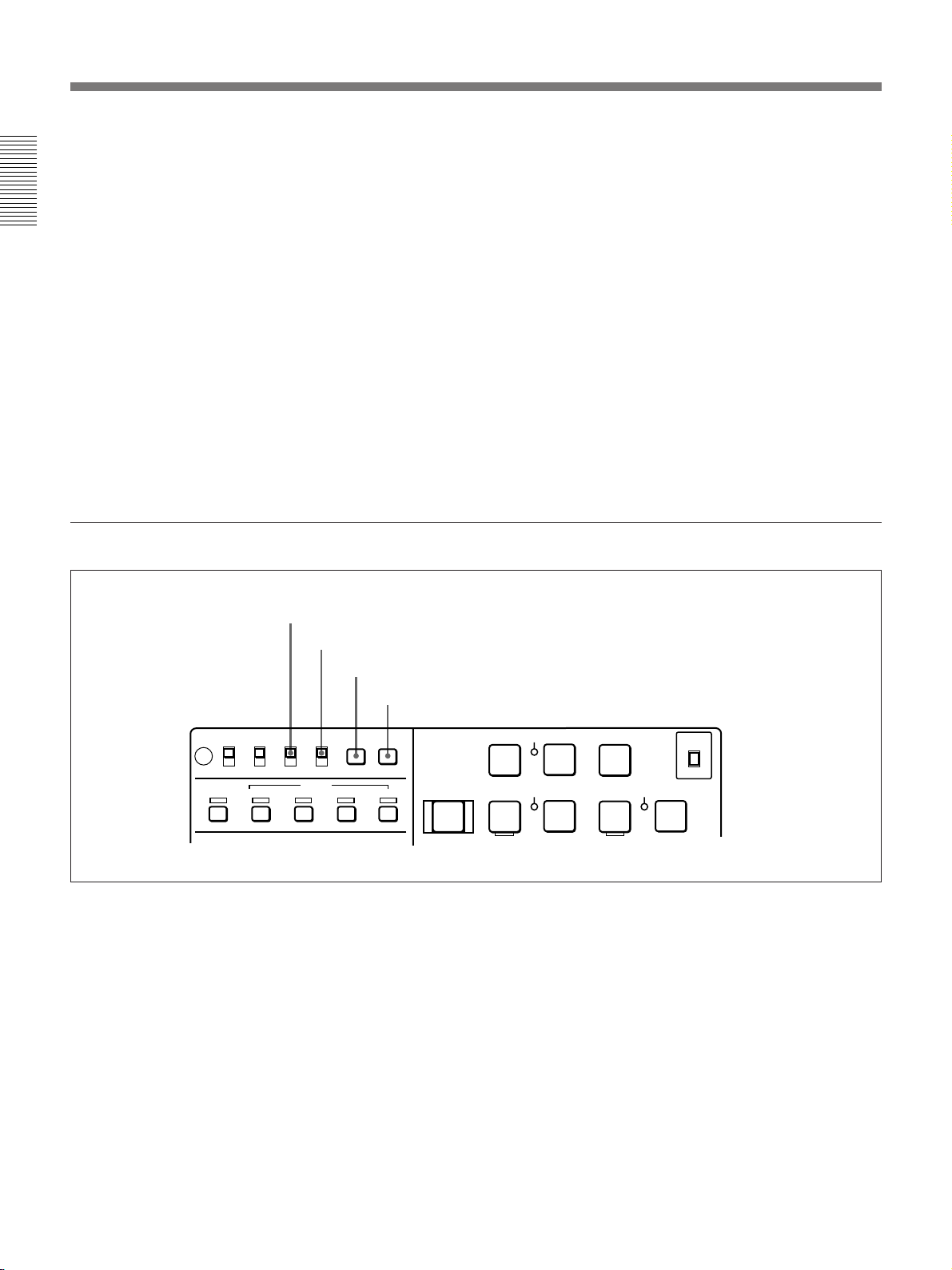
Control Panel
REC INHI switch (tape
transport section)
Editing section
(see page 24)
REMOTE/LOCAL switch (see below)
Timecode and setup menu section
(see page 23)
REC INHI
TC TC SELECT
INT
EXT
AUDIO
CH1,1/2 CH2,3/4
TRIM
CLIP
LINK
ENTRY SHIFT
AUTO EDIT
AUDIO INPUT
PRESET
VARIABLE
PB
AUDIO
PRESET
VARIABLE
MENU
TC
SET
VITC
TC
PLAYER
OFF
LOCAL
REMOTE
ON
ASSEMBLE INSERT
VIDEO
AUDIO IN
– +
LIST MARK
DELETE
IN OUT
PREVIEW REVIEW
CH-1
CH-2 CH-3 CH-4
REC
PREROLL
REC SEQ EDIT
INHI
z
RECORDER
m
REVERSE
SERVO
B
EJECT REW PLAY F FWD
Z
DMC
Tape transport section (see page 21)
METER switch (see “Display Panel” on page 18)
METER
CH-1/2
CH-3/4
STANDBY
STOP
x
M
SHUTTLE
FORWARD
JOG
VAR
Chapter 1 Overview
Audio control section (see page 25)
REMOTE/LOCAL switch
Selects the source for control of this unit.
REMOTE: This unit is controlled from the device
connected to the REMOTE connector. In this
case, all VCR operations using this unit’s control
panel are disabled except the STOP and EJECT
buttons.
When combining two DSR-70A/70AP units as a
pair of recorder and player, set the REMOTE/
LOCAL switch of the player to REMOTE.
LOCAL: This unit is controlled from the control
panel. Normally set the switch to this position.
When the REMOTE is selected, you can determine which
tape transport control buttons on the control panel are
enabled. See setup menu item 006 (page 106).
Chapter 1 Overview 21
Page 22
Location and Function of Parts
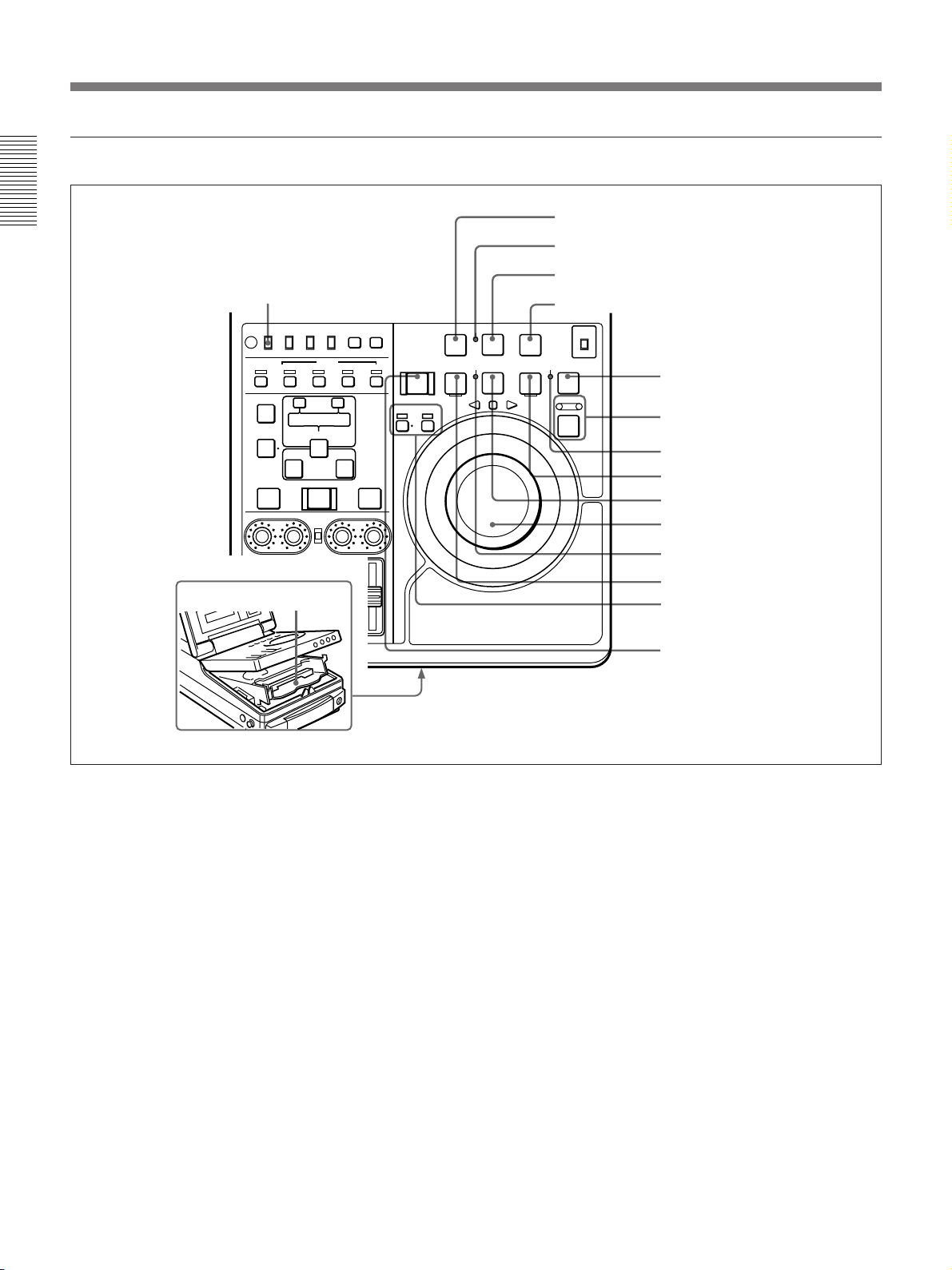
Tape transport section
Chapter 1 Overview
qg REC INHI switch
REC INHI
TC TC SELECT
OFF
LOCAL
INT
ON
REMOTE
ASSEMBLE INSERT
AUDIO IN
DELETE
PREVIEW REVIEW
qh Cassette compartment
EXT
VIDEO
– +
LIST MARK
ENTRY SHIFT
IN OUT
AUTO EDIT
AUDIO INPUT
VARIABLE
CH-1
CH-2 CH-3 CH-4
CH1,1/2 CH2,3/4
TRIM
CLIP
LINK
PRESET
PB
AUDIO
PRESET
VARIABLE
AUDIO
1 PREROLL button
2 REC INHI indicator
3 REC/SEQ button
4 EDIT button
REC
PREROLL
REC SEQ EDIT
m
REVERSE
SERVO
INHI
z
B
M
FORWARD
TC
MENU
SET
VITC
TC
EJECT REW PLAY F FWD
Z
PLAYER
RECORDER
DMC
STANDBY
SHUTTLE
x
VAR
STOP
METER
CH-1/2
CH-3/4
JOG
5 STOP button
6 Search button and indicators
7 STANDBY indicator
8 F FWD button
9 PLAY button
q; Jog and shuttle dials
qa SERVO indicator
qs REW button
qd PLAYER/DMC and
RECORDER buttons and
indicators
qf EJECT button
1 PREROLL button
Press to run the tape up to the preroll point (located in
advance of the IN point by the amount of the preroll
time). You can set the preroll time using setup menu
item 001 (page 106). You can set the state of the unit
at the end of preroll by using setup menu item 401
(page 114).
By pressing this button at the same time as the IN/
OUT or AUDIO IN buttons in the editing section, you
can search for a timecode set in advance and stop at
that position. (The tape is cued up to the preset
timecode position.)
2 REC INHI (recording inhibit) indicator
Lights under the following situations.
• Set the REC INHI switch qg to ON.
• Set the REC/SAVE switch on the cassette to SAVE.
When the REC INHI switch qg is in the OFF position, then
it is possible to make the REC INHI indicator flash in this
state. For details, see setup menu item 107 (page 111).
22 Chapter 1 Overview
3 REC/SEQ (recording/sequence) button
Press together with the PLAY button 9 to start
recording.
When two DSR-70A/70AP units are combined, this
button allows you to perform sequential recording
from one unit to another.
For details, see “Sequential Recording Using Two Units”
(page 45).
To monitor E-E mode
You can monitor input signals in E-E mode by
pressing this button from stop mode. The button lights
when pressed. To return to the original picture, press
the STOP button 5. You can view E-E video during
playback, search, fast forward, and rewind by pressing
this button.
The E-E video continues for as long as the button is
kept pressed.
Page 23

4 EDIT button
Press together with the PLAY button 9 to perform
manual editing.
Press the ENTRY/SHIFT button and STOP button 5
at the same time to switch between standby on and
standby off manually.
To monitor E-E mode
You can monitor input signals in E-E mode by
pressing this button from stop mode. The button lights
when pressed, and the input signals selected with the
ASSEMBLE or INSERT buttons appear in E-E mode.
To return to the original picture, press the STOP
button 5. You can view E-E video during playback,
search, fast forward, and rewind by pressing this
button. The E-E video continues for as long as the
button is kept pressed.
5 STOP button
Press this button, lighting it, to stop playback or
recording. When you stop playback, the LCD monitor
displays E-E or still picture playback, depending on
the PB/EE setting in the sub LCD menu.
Setting setup menu item 105 to ON or LIMIT causes
this button to flash when the input video signal and the
reference video signal are asynchronous.
6 Search button and indicators
Press to enter search mode. (The JOG or SHUTTLE
indicator lights.)
When the unit is in jog or shuttle mode, keep this
button pressed for about 1 second to enter variable
speed mode. (The both indicators light.) To return to
shuttle mode, keep this button pressed again for about
1 second.
In shuttle or variable speed mode, you can start
playback at preset speed by rotating the shuttle dial to
the desired position and pressing this button.
When setup menu item 128 is set to ON, this button
functions as a pause button. You can use the pause
button to make a pause during sequential recording
carried out using two DSR-70A/70AP units.
For more information about tape protection, see the setup
menu items in the 500s (page 114).
8 F FWD (fast forward) button
Press this button, lighting it, to fast forward the tape.
By pressing the TRIM+/MARK button and this button
simultaneously, you can cue up to any Mark IN point
or cue point provided by ClipLink log data.
For details, see Chapter 6 “ClipLink Operation” (page 95).
9 PLAY button
Press this button, lighting it, to start playback.
Recording starts when you press this button together
with the REC/SEQ button 3, and manual editing
starts when you press this button together with the
EDIT button. If you press this button only during
recording or manual editing, recording or manual
editing stops and the unit returns to playback mode.
q; Jog and shuttle dials
To search in shuttle mode, rotate the outer ring (shuttle
dial). To search in shuttle or variable speed mode,
press the inner ring (jog dial) until it clicks and then
rotate. Rotate in the clockwise direction to search in
the forward direction (the FORWARD indicator
lights), and rotate in the counterclockwise direction to
search in the reverse direction (the REVERSE
indicator lights).
For more information about search, see “Finding Edit
Points — Search” (page 81).
qa SERVO indicator
Lights when the drum and capstan are servo-locked.
Chapter 1 Overview
7 STANDBY indicator
Lights when the tape drum is rotating with tension
applied (standby on). It goes out when the drum stops
rotating and tension is released (standby off).
To protect the tape, the unit normally changes to
standby off when stop mode continues for longer than
1 minute. If you operate a dial or any of the tape
transport buttons except STOP 5 while the unit is in
this state, the unit changes to standby on and enters the
mode of the button or dial that you pressed.
qs REW (rewind) button
Press this button, lighting it, to rewind the tape.
Alternatively, by pressing the TRIM+/MARK button
and this button simultaneously, you can cue up to any
Mark IN point or cue point provided by ClipLink log
data.
For details, see Chapter 6 “ClipLink Operation” (page 95).
Chapter 1 Overview 23
Page 24
Location and Function of Parts
qd PLAYER/DMC and RECORDER buttons/
indicators
Press to control a player connected to the REMOTE
(9-pin) connector or DV connector (when DSBK-140/
160A is installed) by remote control (the indicator
Chapter 1 Overview
lights).
PLAYER/DMC button: The buttons of the editing
and tape transport sections on the recorder side of
the control panel work to control the remote
player.
You can also press this button together with the
ENTRY/SHIFT button to put the unit into DMC
edit mode.
For details, see “DMC Editing” (page 89).
Timecode and setup menu section
RECORDER button: The buttons of the editing and
tape transport sections on the recorder side of the
control panel work to control the recorder itself.
qf EJECT button
Press to eject the cassette or open the cassette
compartment qh. The button lights while the cassette is
being ejected.
qg REC INHI switch
When on, recording to the tape is inhibited, regardless
of the setting of the cassette’s REC/SAVE switch.
(The REC INHI indicator 2 lights.)
qh Cassette compartment
Insert a cassette here. Press the EJECT button qf to
open the compartment.
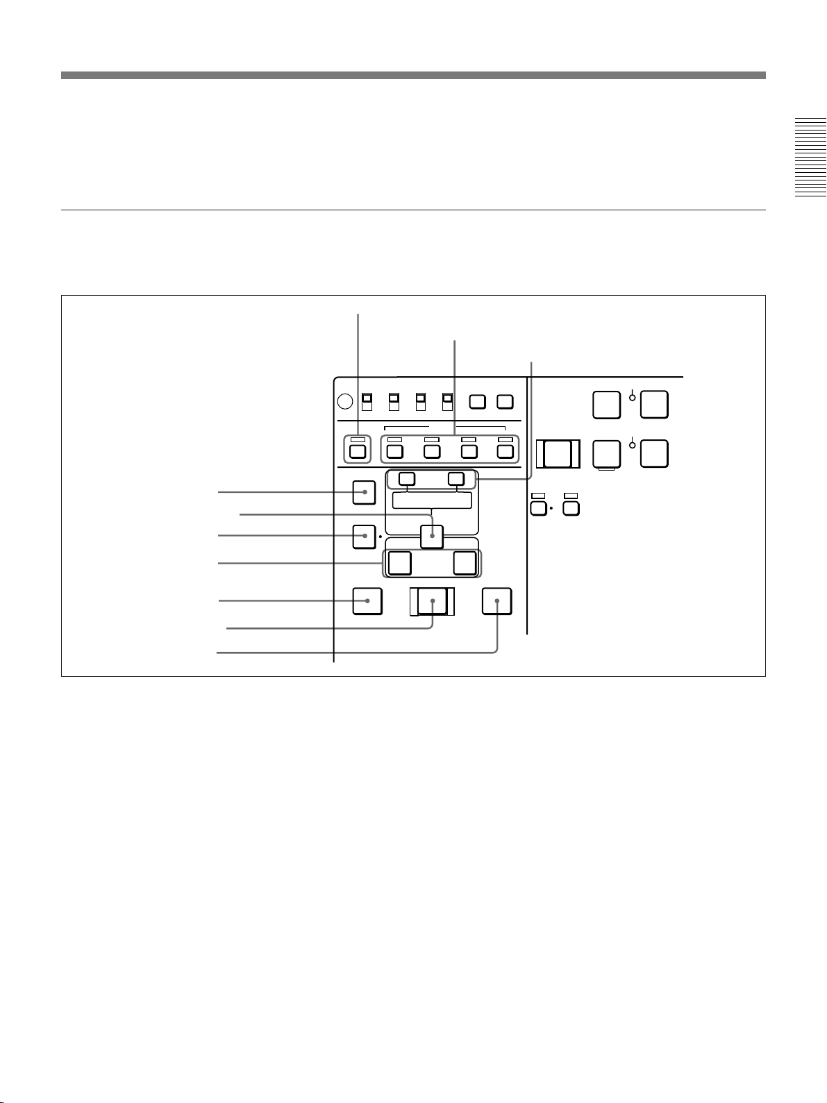
1 TC INT/EXT switch
2 TC SELECT switch
3 MENU button
4 SET button
REC INHI
OFF
LOCAL
ON VITC
REMOTE
ASSEMBLE INSERT
VIDEO
TC SELECT
TC
INT
EXT
AUDIO
CH1,1/2 CH2,3/4
MENUTCSET
TC
1 TC INT/EXT (internal/external timecode)
switch
Selects the timecode to use.
INT: Use the timecode generated by this unit’s built-
in timecode generator.
EXT: The external time code selected as follows.
• When the TC SELECT switch is set to TC
The external time code input to the TIME CODE
IN connector
• When the TC SELECT switch is set to VITC
The VITC time code included in the input video
signal
REC
PREROLL
EJECT REW PLAY F FWD
Z
m
REC SEQ EDIT
INHI
z
SERVO
B
M
2 TC (time code) SELECT switch
This switch selects the time code, TC or VITC, shown
in the time data display.
3 MENU button
Use for setup menu operations. The setup menu
appears on the LCD monitor when you press this
button, and the original display appears when you
press it again.
For more information about setup menu operations, see
Chapter 7 “Setup Menu” (page 105).
STANDBY
STOP
x
METER
CH-1/2
CH-3/4
24 Chapter 1 Overview
Page 25
4 SET button
Use to make setup menu settings, timecode settings,
and user bit settings.
Editing section
Use two DSR-70A/70AP units or one DSR-70A/70AP
unit and an editing player for editing.
1 ASSEMBLE button and indicator
REC INHI
OFF
ON VITC
REMOTE
ASSEMBLE INSERT
AUDIO IN
4 AUDIO IN button
5 ENTRY/SHIFT button
6 DELETE button
7 IN/OUT buttons
8 PREVIEW button
DELETE
PREVIEW REVIEW
For more information about setup menu operations, see
Chapter 7 “Setup Menu” (page 105). For more information
about timecode and user bit settings, see “Setting Time
Data” (page 61).
2 INSERT buttons and indicators
3 TRIM/CLIPLINK buttons
LOCAL
VIDEO
– +
TC SELECT
INT
TC
EXT
AUDIO
CH1,1/2 CH2,3/4
TRIM
CLIP
LIST MARK
LINK
ENTRY SHIFT
IN OUT
AUTO EDIT
MENUTCSET
TC
EJECT REW PLAY
Z
PLAYER
DMC
PREROLL
m
REC
INHI
SERVO
REC SEQ
z
B
Chapter 1 Overview
9 AUTO EDIT button
q; REVIEW button
1 ASSEMBLE button and indicator
Press this button, lighting the indicator, to carry out
assemble editing. Press the button again, turning the
indicator off, to leave assemble edit mode.
2 INSERT buttons and indicators
Press these buttons, turning the indicators on, to select
signals for insert editing. Press the buttons again,
turning the indicators off, to cancel the selection.
VIDEO button: Selects the video signal.
AUDIO “CH1, 1/2 button and AUDIO “CH2, 3/4”
button: When the AUDIO recording mode is 2
channel/48 kHz these select CH-1 (channel 1) or
CH-2.
When the AUDIO recording mode is 4 channel/32
kHz, these select CH-1 and CH-2 (channels 1 and
2) or CH-3 and CH-4.
In this case it is not possible to select channels 1
to 4 individually.
TC button: Selects the timecode signal.
3 TRIM/CLIPLINK buttons
Press the +/MARK or –/LIST buttons while pressing
the IN/OUT buttons 7 or AUDIO IN button 4 to
adjust edit points in unit of 1 frame. The +/MARK
button advances 1 frame, and the –/LIST button
returns 1 frame.
By pressing the TRIM+/MARK button and the F FWD
or REW button simultaneously, you can cue up to any
Mark IN point or cue point provided by ClipLink log
data.
For details, see Chapter 6 “ClipLink Operation” (page 95).
During two-camera switched recording carried out
using the optional DSBK-180/180P board, you can
switch between the composite video signals from the
two video cameras by pressing the +/MARK button
and the –/LIST button at the same time.
Chapter 1 Overview 25
Page 26
Location and Function of Parts
For more information about two-camera switched
recording, see “Two-Input Switched Video Recording”
(page 48).
4 AUDIO IN button
Chapter 1 Overview
In insert editing, press this button together with the
ENTRY/SHIFT button 5 to set audio IN point
separately from video IN point (audio split editing).
After setting audio IN points, you can press this button
alone to display them in the sub LCD.
5 ENTRY/SHIFT button
Press together with the IN button, OUT button 7, or
AUDIO IN button 4 to set edit points. The buttons for
the edit points that you set light.
Pressing this button together with a button with two
functions, such as the PLAYER/DMC button or REC/
SEQ button, selects the function indicated in orange on
the button.
6 DELETE button
Press together with the IN/OUT buttons 7 or the
AUDIO IN button 4 to delete edit points. The buttons
go out or flash. A flashing button indicates that the edit
point needs to be set again.
The DELETE button flashes to indicate contradictions
that will prevent previews and automatic editing, for
example when the durations are different on the player
and recorder, or when the IN and OUT points are equal
or reversed. In this case, set the edit points again.
7 IN/OUT (IN point/OUT point) buttons
Press these buttons, lighting them, together with the
ENTRY/SHIFT button 5 to set an IN point (edit start
point) or OUT point (end point). After setting edit
points, you can press either of these buttons alone to
display the IN or OUT point in the sub LCD.
8 PREVIEW button
Press this button, lighting it, when you want to preview
editing results on the monitor after setting edit points
but before executing an edit or to set the player
playback speed for DMC editing. If an IN point has
not been set, the point where you press this button is
used as the IN point in the preview. This button lights
during the preview and goes out when the preview
finishes.
9 AUTO EDIT button
After setting edit points, press this button, lighting it to
execute an automatic edit (record to the recorder). If an
IN point has not been set, the point where you press
this button is used as the IN point in the automatic edit.
This button lights during execution and goes out when
execution finishes.
Pressing this button when the unit is in DMC edit
mode executes a DMC edit.
To conduct DMC editing, a playback speed must be set in
advance. For details, see “DMC Editing” (page 89).
q; REVIEW button
After executing an automatic edit, press this button,
lighting it to review the results of the edit.
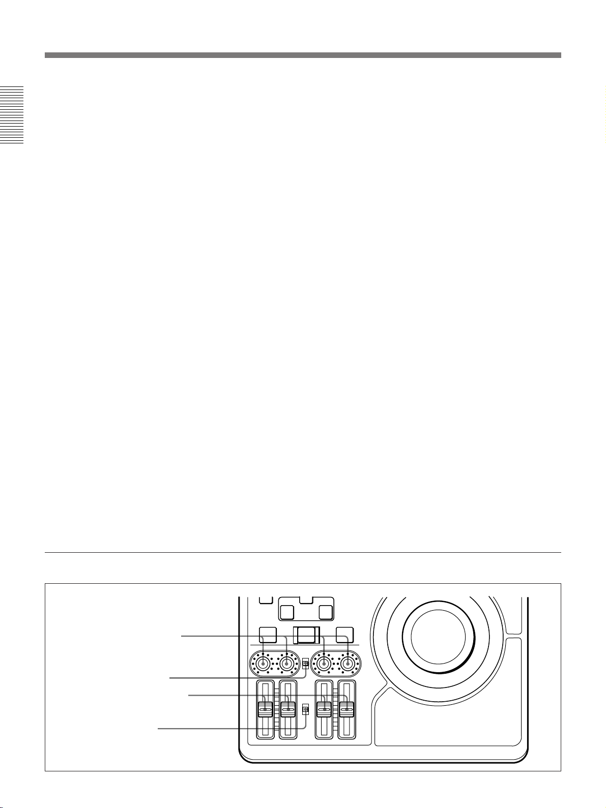
Audio control section
1 AUDIO INPUT CH-1 to CH-4
level adjustment knobs
2 AUDIO INPUT PRESET/
VARIABLE switch
3 PB AUDIO CH-1 to CH-4 level
adjustment sliders
4 PB AUDIO PRESET/
VARIABLE switch
26 Chapter 1 Overview
IN OUT
PREVIEW REVIEW
CH-1
AUTO EDIT
AUDIO INPUT
PRESET
VARIABLE
PB
AUDIO
PRESET
VARIABLE
CH-2 CH-3 CH-4
Page 27
1 AUDIO INPUT CH-1 to CH-4 level adjustment
knobs
Adjust the levels for each channel of analog audio
signals input to the AUDIO INPUT CH-1/CH-2
connectors on the rear panel, or of the audio signals
input to the SDI, SDTI(QSDI), and DV IN/OUT
connectors of the optional boards.
2 AUDIO INPUT PRESET/VARIABLE switch
Select the adjustment function for the levels of analog
audio signals input to the AUDIO INPUT CH-1/CH-2
connectors on the rear panel, or of the audio signals
input to the SDI, SDTI(QSDI), and DV IN/OUT
connectors of the optional boards.
PRESET: Preset to fixed levels. Levels cannot be
adjusted with the level adjustment knobs.
VARIABLE: Levels adjustable with level
adjustment knobs. This allows you to adjust the
levels while viewing the audio level meters in E-E
mode.
For more information about switching to E-E mode, see the
Front Control Section
descriptions of the REC/SEQ and EDIT buttons (pages 21
and 22)
3 PB AUDIO CH-1 to CH-4 level adjustment
sliders
Make level adjustments by channel for playback audio
channels 1 to 4. You cannot adjust the levels of audio
signals output to the SDTI(QSDI) OUT connector or
DV IN/OUT connector attached to an optional board
(DSBK-140/150/160A).
4 PB AUDIO PRESET/VARIABLE switch
Selects the level adjustment function for playback
audio.
PRESET: Preset to fixed levels. Levels cannot be
adjusted with the level adjustment sliders.
VARIABLE: Levels adjustable with the level
adjustment sliders. This allows you to adjust the
levels while viewing the audio level meter.
Chapter 1 Overview
8 POWER switch
1 VIDEO knob
Adjusts the video signal output level. This knob is a
push switch. When you press it to bring it into the
raised position, the setting becomes VARIABLE.
When you press it again to depress it, the setting
returns to PRESET.
PRESET: This is the normal setting. Regardless of
the knob position, the video signal output level is
set to the standard value.
VARIABLE: The video signal output level can be
adjusted across a range of ±3 dB.
1 VIDEO knob
2 CHROMA knob
3 SET UP/BLACK LEVEL knob
4 CHROMA PHASE knob
5 POWER indicator
6 LEVEL knob
7 HEADPHONES jack
2 CHROMA knob
Adjusts the chroma signal output level. This knob is a
push switch. When you press it to bring it into the
raised position, the setting becomes VARIABLE.
When you press it again to depress it, the setting
returns to PRESET.
PRESET: This is the normal setting. Regardless of
the knob position, the chroma signal output level
is set to the standard value.
VARIABLE: The chroma signal output level can be
adjusted across a range of ±3 dB.
You can change the adjustment range by using setup menu
item 714. For details, see page 116.
You can change the adjustment range by using setup menu
item 714. For details, see page 116.
Chapter 1 Overview 27
Page 28
Location and Function of Parts
3 SET UP/BLACK LEVEL knob
Adjusts the setup level (for DSR-70A) or the black
level (for DSR-70AP). This knob is a push switch.
When you press it to bring it into the raised position,
the setting becomes VARIABLE. When you press it
Chapter 1 Overview
again to depress it, the setting returns to PRESET.
PRESET: This is the normal setting. Regardless of
the knob position, the setup level (for DSR-70A)
or the black level (for DSR-70AP) is set to the
standard value.
VARIABLE: The setup level can be adjusted across
a range of ±30 IRE (for DSR-70A) and the black
level can be adjusted across a range of ±210 mV
(for DSR-70AP).
4 CHROMA PHASE knob
Adjusts the chroma phase (phase relative to burst).
This knob is a push switch. When you press it to bring
it into the raised position, the setting becomes
VARIABLE. When you press it again to depress it, the
setting returns to PRESET.
PRESET: This is the normal setting. Regardless of
the knob position, the chroma phase is set to the
standard value.
VARIABLE: The chroma phase can be adjusted
across a range of ±30˚.
5 POWER indicator
Lights green when the POWER switch 8 is turned on,
and changes to red when recording starts.
6 LEVEL (speaker/headphones level) knob
Adjusts the volume of the speaker or headphones
connected to the HEADPHONES jack 7.
7 HEADPHONES jack (stereo phone jack)
Connect headphones. The speaker is muted when
headphones are connected.
8 POWER switch
Powers the unit on and off. When the unit is powered,
the POWER indicator 5 lights.
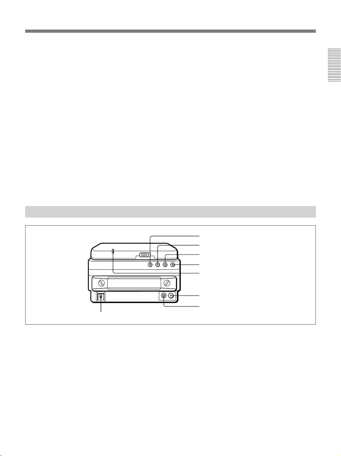
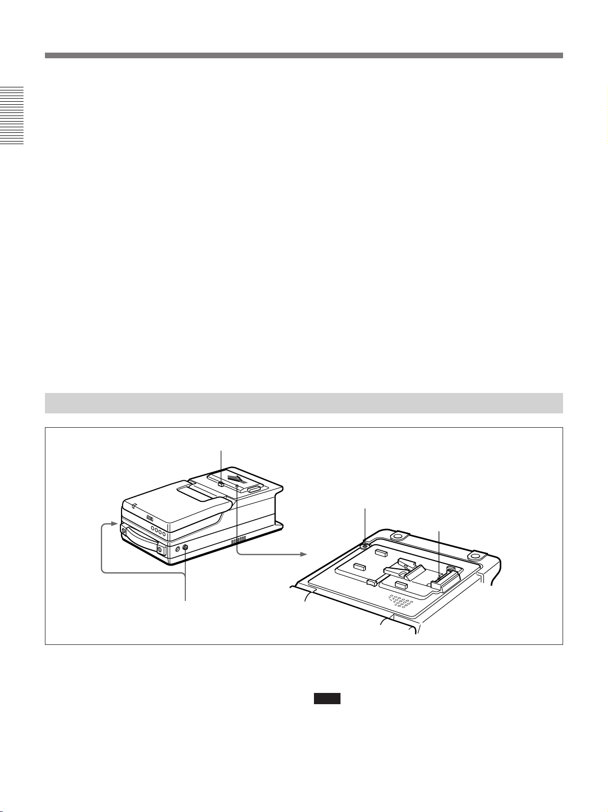
Top Panel
Slide the cover off while pressing the lever.
3 Shoulder belt attachment
fixture
1 Battery connector
Connect a BP-L60/L60A//L90/L90A Battery Pack,
DC-L90 Battery Adaptor, or AC-DN2A/DN2B AC
Adaptor.
When the AC-550/550CE AC Adaptor or another
power supply has been connected to the DC IN
connector on the rear panel, the power from the DC IN
connector is used instead of the power from this
connector.
2 BREAKER button
1 Battery connector
For more information, see “Power Preparations” (page
33).
Note
The AC-DN1 AC Adaptor and the BP-L40 and NP-1B
Battery Packs cannot be used.
28 Chapter 1 Overview
Page 29
2 BREAKER button
When excess power flows inside the unit, the breaker
activates to protect the circuits by automatically
shutting down the power. After inspecting and
adjusting the unit, press this button. If there is no
further trouble, the power will be restored.
For inspection and adjustment of the unit, consult your Sony
dealer.
Rear Panel
Analog audio/video input and output section
3 Shoulder belt attachment fixture
Attach the supplied shoulder belt.
For more information, see “Using the Shoulder Belt” (page
135).
5 REF. VIDEO IN/OUT connectors and 75Ω termination switch
6 VIDEO INPUT connectors and 75Ω termination switch
7 VIDEO OUTPUT 1 and 2 (SUPER) connectors
Chapter 1 Overview
1 48V ON/OFF switches
AUDIO INPUT VIDEO
2 AUDIO INPUT CH-1/CH-2
level switches
-60 +4dbu
CH-1 CH-2
0
0
-60 +4dbu
3 AUDIO INPUT CH-1/CH-2
connectors
AUDIO OUTPUT
1/3 2/4
4 AUDIO OUTPUT CH-1/3 and
CH-2/4 connectors
This illustration shows the DSR-70A/70AP fitted with the optional DSBK-170.
1 48V ON/OFF switches
When the AUDIO INPUT CH-1/CH-2 level switches
are set to –60 dBu, setting these switches to ON causes
48-V power to be supplied to the AUDIO INPUT
connectors.
2 AUDIO INPUT CH-1/CH-2 level switches
Select the input level of the analog audio signals of
input channels 1 and 2.
ONOFF
ONOFF
75Ω 75Ω
REF. INPUT
IN
OUT
MONITOR
AUDIO
IN
OUT
S VIDEO
OUTPUT
1
2(SUPER)
REMOTE
Y
R-Y B-Y
DC IN
TC IN
OUTIN
TC OUT
8 S VIDEO IN/OUT connectors
9 MONITOR AUDIO connector
–60 dBu: Microphone input
0 dBu: Line audio input
+4 dBu: Line audio input (0 dBu = 0.775 Vrms)
For microphone inputs, use 48-V microphones, and set
the AUDIO INPUT CH-1/CH-2 level switches 2 to
–60 dBu and the 48V ON/OFF switches 1 to ON,
respectively.
Caution
Using a microphone other than a 48-V microphone
may damage the microphone.
Chapter 1 Overview 29
Page 30

Location and Function of Parts
3 AUDIO INPUT CH-1/CH-2 connectors (XLR 3pin, female)
Input the analog audio signals of input channels 1 and
2.
Chapter 1 Overview
4 AUDIO OUTPUT CH-1/3 and CH-2/4
connectors (XLR 3-pin, male)
Output the audio signals of the channels selected with
the sub LCD menu item LINE OUT. You can select
two combinations of output signals: channels 1 and 2,
or channels 3 and 4.
For more information about LINE OUT settings, see page
71.
Note
The level can be adjusted from the control panel, but
mixed signals cannot be output.
5 REF. VIDEO IN/OUT (reference video signal
input/output) connectors (BNC type) and 75Ω
termination switch
When using an external reference video signal, input it
to one of the REF. VIDEO IN connectors. Set the 75Ω
termination switch to OFF when the signal is bridged,
and to ON when the signal is not bridged.
The REF. VIDEO OUT connector outputs a reference
video signal.
8 S VIDEO IN/OUT connectors (4-pin)
Input an S-video signal with separated Y (luminance)
and C (chroma: 3.58 MHz for DSR-70A and 4.43
MHz for DSR-70AP) components to the S VIDEO IN
connector.
The S VIDEO OUT connector outputs an S-video
signal.
9 MONITOR AUDIO connector (phono jack)
Output the audio signals of the channels selected with
the sub LCD menu item MONITOR. The level is
adjustable, and mixing is possible.
For more information about the MONITOR item, see page
71.
6 VIDEO INPUT (analog composite video input)
connectors (BNC type) and 75Ω termination switch
Input an analog composite video signal. Set the 75Ω
termination switch to OFF when the signal is bridged,
and to ON when the signal is not bridged.
7 VIDEO OUTPUT (analog composite video
output) 1 and 2 (SUPER) connectors (BNC type)
Output analog composite video signals. When the sub
LCD menu item CHARACTER is set to ON,
timecode, menu settings, error messages and other
information is superimposed on the output of 2
(SUPER) connector.
For details about the superimposed information, see page
61.
30 Chapter 1 Overview
Page 31

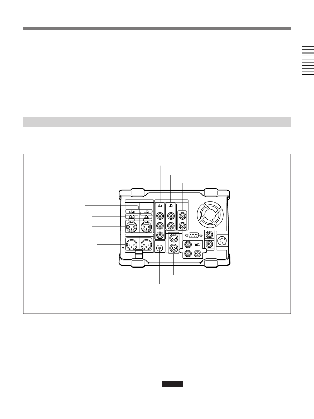
Optional board/timecode/remote control/power input and output section
AUDIO INPUT VIDEO
0
0
-60 +4dbu
-60 +4dbu
CH-1 CH-2
AUDIO OUTPUT
1/3 2/4
ONOFF
75Ω 75Ω
REF. INPUT
IN
OUT
MONITOR
AUDIO
IN
OUT
ONOFF
S VIDEO
OUTPUT
1
2(SUPER)
REMOTE
Y
R-Y B-Y
TC IN
OUTIN
TC OUT
Cable clamp
a) This illustration shows the DSR-70A/70AP fitted with the optional DSBK-170.
1 REMOTE (9-pin remote control) connector
(D-sub 9-pin)
When editing with two DSR-70A/70AP units, connect
this connector on each unit using a 9-pin remote
control cable (not supplied). When editing with this
unit and external equipment, connect the external
equipment.
2 TC IN (timecode input) connector (BNC type)
To record timecode from an external device, input the
timecode from the external device’s timecode output
connector.
3 DC IN (external power input) connector (XLR
4-pin, male)
To power this unit with AC power, connect to the DC
output connector of the AC-550/550CE AC adaptor.
You can also connect a BP-90/90A Battery Pack using
the DC-210 Battery Adaptor.
Power supplied through this connector is used on a
priority basis even when you have connected a battery
pack or AC-DN2A/DN2B AC Adaptor to the battery
connector on the top panel.
1 REMOTE connector
DC IN
2 TC IN connector
3 DC IN connector
4 TC OUT connector
5 Optional interface board fitting port
a)
4 TC OUT (timecode output) connector
(BNC type)
Outputs the following types of timecode, depending on
the VCR operating status.
During playback: The playback timecode
During recording: The timecode generated by the
internal timecode generator, or the timecode input
through the TC IN connector.
For details of the timecode output during recording, see
setup menu item 611 (page 116).
5 Optional interface board fitting port
Install any one of the following optional interface
boards here:
• DSBK-140 i.LINK/DV Input/Output Board
• DSBK-150 SDTI (QSDI) Input/Output Board
• DSBK-160A SDI/i.LINK/DV Input/Output Board
• DSBK-170 Analog Component Input/Output Board
The connectors provided by the optional boards are as
follows.
Chapter 1 Overview
For more information, see “Power Preparations” (page
33).
Chapter 1 Overview 31
Page 32

Location and Function of Parts
Connector of the DSBK-140
Chapter 1 Overview
DV IN/OUT (DV input/output) connector (6-pin
IEEE1394 connector): This connector is i.LINK
compatible. Connect to another DSR-70A/70AP
unit or a consumer DV camera to carry out such
operations as recording and editing.
Connectors of the DSBK-150
DV IN/OUT
SDTI(QSDI)
IN
SDTI(QSDI)
OUT
Connectors of the DSBK-170
Y
R-Y B-Y
OUTIN
IN/OUT switch
Y, R–Y, B–Y (luminance and color difference
signal) input/output connectors (BNC type): Use to
input or output analog component signals (Y,
R–Y, B–Y). When using as input connectors, set
the IN/OUT switch to IN. When using as output
connectors, set the IN/OUT switch to OUT.
SDTI(QSDI) IN/OUT (input/output) connectors
(BNC type): Use to input/output digital video/audio
signals in SDTI(QSDI) format.
Connectors of the DSBK-160A
SDI
IN OUT
DV IN/OUT
SDI IN/OUT (serial digital interface signal input/
output) connectors (BNC type): Use to input/output
digital video/audio signals in SDI (D1) format.
DV IN/OUT (DV input/output) connector (6-pin
IEEE1394 connector): This connector is i.LINK
compatible. Connect to another DSR-70A/70AP
unit or a consumer DV camera to carry out such
operations as recording and editing.
32 Chapter 1 Overview
Page 33

Power Preparations
Power Preparations
This unit can be powered by batteries or AC power.
Example battery packs and AC adaptors that can be used are shown below.
Chapter2
Chapter 2 Power Preparations
Usable Batteries
Battery pack Battery
BP-90A DC-L90
Note
adapter
Battery pack AC adaptor
BP-L60/BP-L60A/
BP-L90/BP-L90A
AC-DN2A/
DN2B
AC-550/
550CE
CMA-8A/
8ACE
If you attach or remove batteries or AC adaptors incorrectly, they may fall
down and cause body injury.
Follow the procedures described below to attach or remove them.
Batteries that can be used with this unit are as follows. For each type of
battery, a special battery adaptor and battery charger is required.
Battery Battery Adaptor Battery Charger
BP-90/90A (mounted on this unit) DC-L90 BC-210/210CE/
BP-90/90A (connected to DC IN
connector)
BP-L60/L60A/L90/L90A Not needed BC-L120/L100/
DC-210 BC-210/210CE/
410/410CE
410/410CE
L100CE/L50
In the subsequent pages, the batteries such as the BP-90/90A and BP-L60/
L60A will also be referred to as the BP-90(A) and BP-L60(A).
Chapter 2 Power Preparations 33
Page 34

Power Preparations
Notes about battery usage
• Before using the batteries, be sure to charge them fully with the special
battery charger. Refer to the operating instructions of your battery charger
for more information about how to charge the batteries.
• Batteries may not be completely charged if you charge them immediately
after use when they are still warm. You should wait until the batteries
cool before charging them.
Using the BP-L60(A)/L90(A) Battery Pack
Chapter 2 Power Preparations
To attach the battery pack
This unit can be operated for about 120 minutes at normal temperature on
fully charged BP-L90 Battery Pack. (When no optional board is installed.)
To charge the battery pack
Before use, charge the battery pack with the BC-L100/L100CE Battery
Charger. It takes about 2.5 hours to charge the BP-L60(A) and about 3.5
hours to charge the BP-L90(A).
For more information about how to charge the battery pack, refer to the manual
for the BC-L100/L100CE.
Attach the BP-L60(A)/L90(A) as shown in the following figure. Before
attaching, remove the cover of the battery connector.
Remove the cover in the same way that you remove the battery pack. For details
see the next section “To remove the battery pack.”
1Align the groove on the top panel of
the BP-L60(A)/L90(A) with the
guides.
2Slide the BP-L60(A)/L90(A) in so
that its connector is firmly
connected to the unit’s battery
connector.
34 Chapter 2 Power Preparations
Page 35

To remove the battery pack
With the lever pushed in, slide the BP-L60(A)/L90(A) out.
BP-L60(A)/L90(A)
Using the BP-90(A) Battery Pack
Different battery adaptors are used when mounting the BP-90(A) on the
top panel of this unit and when connecting it the DC IN connector.
This unit can be operated for about 70 minutes at normal temperature on a
fully charged BP-90(A) Battery Pack. (When no optional board is
installed.)
To charge the battery pack
Before use, be sure to charge the battery pack with the BC-210/210CE/
410/410CE Battery Charger. It takes about 2 hours to charge the BP90(A).
For more information about how to charge the battery pack, refer to the manual
for the BC-210/210CE/410/410CE.
To attach to the top panel of this unit
Lever
Chapter 2 Power Preparations
Use the DC-L90 Battery Adaptor.
1 Mount the BP-90(A) in the DC-L90.
1 Lift the lever up.
2 Open the side cover.
3 Insert the BP-90(A).
4 Push the plug in.
5 Close the side cover and
pull the lever down.
(Continued)
Chapter 2 Power Preparations 35
Page 36

Power Preparations
2 Attach the DC-L90 to the top panel of this unit.
Use the same method that you use to attach the BP-L60(A)/L90(A).
For details, see “To attach the battery pack” (page 34).
To connect to the DC IN connector
Use the DC-210 Battery Adaptor.
Chapter 2 Power Preparations
For more information about connections, refer to the operating instructions of the
DC-210.
You can also connect another battery pack to the DC IN connector when a
BP-90(A) battery pack is already mounted on the top panel of this unit.
When you connect an external battery pack to the DC IN connector, the
power supply automatically switches to the external battery pack from an
internal battery pack mounted on the top panel of the unit.
Notes
• Noise may occur in video and audio signals at the moment when the unit
switches from the internal to the external battery.
• It is always the external battery connected to the DC IN connector that
serves as power supply. You cannot switch the power supply from the
external battery to the internal battery while the external battery is
connected to the DC IN connector.
When an external battery pack is almost exhausted
If an internal battery pack is already mounted, disconnect the external
battery pack by pulling its DC power cord out from the DC IN connector.
If no internal battery back is mounted, disconnect the external battery pack
after mounting a fully charged internal battery pack.
Using AC Power
36 Chapter 2 Power Preparations
When an internal battery pack is almost exhausted
For the remaining battery power indication (see page 67), the “BATT”
display flashes.
Connect a fully charged external battery pack to the DC IN connector, then
exchange the internal battery pack.
You can operate the unit from an AC power source by using the AC-550/
550CE AC Adaptor or AC-DN2A/DN2B AC Adaptor.
Use the AC-550/550CE to connect the AC power source to the DC IN
connector, and the AC-DN2A/DN2B to connect the AC power source to
the battery connector.
Page 37

To use the AC-550/550CE
As shown in the following figure, connect the AC-550/550CE to the AC
power source and turn it on.
When you connect AC power, the power supply automatically switches to
the AC power from a battery pack mounted on the top panel of the unit.
Note
Noise may occur in video and audio signals at the moment when the unit
switches from the battery pack to AC power.
Chapter 2 Power Preparations
POWER switch: ON
AC-550/550CE
To AC power
To use the AC-DN2A/DN2B
DC IN
DC power cord (supplied with AC-550/550CE)
DC OUT
AC power cord
(supplied with AC-550/550CE)
Follow the procedure below to mount the AC-DN2A/DN2B on the top
panel of this unit, and connect to AC power.
When two DSR-70A/70AP units are combined, you can supply both units
with power by fitting a single AC-DN2A/DN2B to either unit.
Caution
When you use a single AC-DN2A/DN2B to supply power to two DSR70A/70AP units, exercise the following caution:
• Do not turn the POWER switches of both units on at a time. (Turn one
unit on, then wait a moment before turning the other unit on.)
• Do not insert cassettes into both units at a time. (Insert a cassette into one
unit, then wait a moment before inserting a cassette into the other unit.)
If you turn on the POWER switches of the recorder and player at a time or
insert cassettes to the recorder and player at a time, this unit possibly may
not be powered. In this case, turn the POWER switches of both units off,
then turn them on again following the above instructions. Should this unit
not be powered, turn both POWER switches off and disconnect the AC
power cord of the AC-DN2A/DN2B. After about 10 minutes, connect the
AC power cord of the AC-DN2A/DN2B again and turn the two units’
POWER switches on one by one as mentioned above.
Chapter 2 Power Preparations 37
Page 38

Power Preparations
Chapter 2 Power Preparations
1 Remove the cover of the battery connector.
2 Insert the V-wedge shoe on the AC-DN2A/DN2B in the V-groove on
one unit and slide the AC-DN2A/DN2B until the battery charging
connector is connected to the battery connector.
Battery charging
connector
Battery connector
3 Use the DC power cord (supplied with the AC-DN2A/DN2B) to
connect the DC output connector on the AC-DN2A/DN2B and the DC
IN connector on the rear of another unit.
To DC output connector
DC IN
DC power cord
(supplied with the
AC-DN2A/DN2B)
38 Chapter 2 Power Preparations
4 Supply the AC-DN2A/DN2B with AC power.
For information about how to supply AC power to the AC-DN2A/DN2B, refer
to the manual for the AC-DN2A/DN2B.
Page 39

Recording and
Playback
Handling Cassettes
This unit can use standard-size and mini-size DVCAM cassettes listed
below.
Model name Size
PDV-64ME/94ME/124ME/184ME Standard size
PDVM-12ME/22ME/32ME/40ME Mini size
Chapter3
Chapter 3 Recording and Playback
The numbers in each model name indicate the maximum recording/
playback time (in minutes) for each model. For example, the PDV-184ME
has a maximum recording/playback time of 184 minutes.
Cassettes usable for playback only
All consumer DV cassettes and L- and M-size DVCPRO (25M) cassettes
are usable for playback only.
Notes
• If you insert an incorrect type of cassette, it will be automatically ejected.
• When operating this unit as a player, you can also use DV cassettes on
the unit. However, it is the best choice to always use DVCAM cassettes
because they are more reliable than DV cassettes whatever your purpose
may be: playback, editing, or long-period storage of recordings.
• Cassettes that have been recorded by a DV-format recorder can be played
back on this unit, but you cannot use them to carry out recording by
editing. If you insert such a cassette into this unit, the NO EDIT
indication lights up in the sub LCD menu home page.
Chapter 3 Recording and Playback 39
Page 40

Handling Cassettes
DVCAM cassettes
The following figure illustrates the DVCAM cassette’s appearance.
Standard size
Mini size
Chapter 3 Recording and Playback
Notes on using cassettes
REC/SAVE switch
For details of this switch, see
“Preventing accidental erasure”
(on this page).
Cassette memory
This memory is used to store ClipLink
log data. For details of ClipLink log data,
see the appendix “ClipLink Guide” (page
149).
• Before storing the cassette, rewind the tape to the beginning and be sure
to put the cassette in its storage case, preferably on end instead of flat on
its side. The storage case of a DVCAM cassette is specially designed to
ensure a long-period storage of the tape.
Storing a cassette in any other condition (not rewound, out of its case,
etc.) may cause the video and audio contents to become damaged over
time.
• If the cassette memory connector (contact point) becomes dirty,
connection problems may occur and cause a loss of functions. Remove
away any dust or dirt from this area before using the cassette.
• If the cassette is dropped on the floor or otherwise receives a hard impact,
the tape may become slackened and may not record and/or play back
correctly.
For instructions on removing tape slack, see page 41.
Preventing accidental erasure
40 Chapter 3 Recording and Playback
Set the REC/SAVE switch on the cassette to SAVE to prevent accidental
erasure of recorded contents.
REC/SAVE switch
Set to SAVE.
REC
SAVE
Page 41

Checking the tape for slack
To enable re-recording
Set the cassette’s REC/SAVE switch to REC.
If you insert a cassette into the unit when this switch is set to SAVE, the
unit will not record when you press the PLAY button while holding down
the REC/SEQ button.
Using a paper clip or a similar object, turn the reel gently in the direction
shown by the arrow. If the reel does not move, there is no slack. Insert the
cassette into the cassette compartment, and after about 10 seconds take it
out.
Paper clip, etc.
Chapter 3 Recording and Playback
Reel
Chapter 3 Recording and Playback 41
Page 42

1
2
3
EJECT REW PLAY F FWD
SERVO
STOP
STANDBY
Z
m
B
M
x
Handling Cassettes
Loading/Ejecting Cassettes
To load a cassette
Chapter 3 Recording and Playback
LCD indicator
STANDBY indicator
1 With the unit powered on, press the EJECT button.
The control panel lifts up and the cassette compartment opens.
2 Load a cassette in the direction shown in the figure.
The message “CASSETTE OUT” displayed on the LCD monitor
changes to “TAPE UNTHREAD.”
Note
If the message on the LCD monitor does not change to “TAPE
UNTHREAD,” redo the cassette insertion procedure.
Loaded cassette position
Standard size
M size
Mini size
42 Chapter 3 Recording and Playback
3 Close the control panel. (You should hear a click.)
The STANDBY indicator lights.
Page 43

To eject the cassette
1
2
1 With the unit powered on, press the EJECT button.
The control panel lifts up and the cassette compartment opens.
2 Remove the cassette and close the control panel.
Notes
• Do not shut the display panel while the control panel is still open. Doing
so may damage the lock mechanism of the display panel.
• The EJECT button cannot be used to eject a cassette when battery power
falls to below about 9 V. Connect an external power supply.
Chapter 3 Recording and Playback
Chapter 3 Recording and Playback 43
Page 44

Recording
This section describes recording of external input signals using this unit as
a recorder.
Notes
• When two DSR-70A/70AP units are combined, set both REMOTE/
LOCAL switches to LOCAL.
• When controlling this unit from the editing control unit connected to the
REMOTE connector, set the REMOTE/LOCAL switch to REMOTE.
Preparations for Recording
Perform the following procedure.
1 Connect the source signals.
Chapter 3 Recording and Playback
To adjust audio input levels
Recording Operation
2 Select video and audio signals which you want to record (see step
5
on
page 76).
3 Make settings for time data (see page 61).
Set the AUDIO INPUT PRESET/VARIABLE switch on the control panel
to VARIABLE. Turn the AUDIO INPUT CH-1 and CH-2 knobs,
monitoring the input levels indicated by audio level meter.
Confirm that the REC INHI indicator on the control panel is not lit.
Then, follow the procedure below.
44 Chapter 3 Recording and Playback
REC
PREROLL
REC SEQ EDIT
INHI
z
m
SERVO
B
M
EJECT REW PLAY F FWD
Z
STANDBY
21
METER
CH-1/2
CH-3/4
STOP
x
Page 45

1 Press the REC/SEQ and PLAY buttons at the same time.
Recording starts and the POWER indicator turns to red.
2 Press the STOP button to stop recording.
If recording continues to the end of the tape, the tape automatically
rewinds to the beginning and stops.
Sequential Recording Using Two Units
When you combine two DSR-70A/70AP units, you can perform sequential
recording from one unit to another. (In the following explanation of twounit sequential recording, the controlling unit is referred to as the recorder
and the controlled unit as the player.)
For overwriting recording using only two cassettes, the last 6 hours of
recording is always available.
By replacing the cassette approximately every 3 hours, indefinite
continuous recording is possible.
Sequential recording using two DSR-70A/70AP units can be performed in
the following two ways.
• Inputting external video and audio signals to both the player and recorder.
• Inputting external video and audio signals to the player and inputting the
video and audio signals output from the player to the recorder.
In either case, you can use the same operating procedure, but there are
some differences in equipment/signal connections and basic settings
between the two cases.
Chapter 3 Recording and Playback
For more information about equipment/signal connections and basic settings for
two-unit sequential recording, see “Connections for Sequential Recording Using
Two Units” (page 127).
Use the following procedure. You can do control panel operations on the
recorder during sequential recording. Rewind the tape to the beginnig
beforehand.
3
TC TC SELECT
REC INHI
OFF
LOCAL
INT
ON
REMOTE
ASSEMBLE INSERT
AUDIO IN
DELETE
EXT
VIDEO
AUDIO
CH1,1/2 CH2,3/4
– +
TRIM
CLIP
LIST MARK
LINK
ENTRY SHIFT
IN OUT
TC
SET
MENU
VITC
TC
EJECT REW PLAY F FWD
Z
PLAYER
RECORDER
DMC
PREROLL
m
REVERSE
REC
REC SEQ EDIT
INHI
z
SERVO
B
M
FORWARD
STANDBY
SHUTTLE
x
VAR
STOP
METER
CH-1/2
CH-3/4
JOG
2
Chapter 3 Recording and Playback 45
Page 46

Recording
Chapter 3 Recording and Playback
1 Insert the cassettes into the recorder and player.
2 Press the recorder side RECORDER button to light the RECORDER
indicator on the recorder.
3 Simultaneously press the recorder side ENTRY/SHIFT button, REC/
SEQ button, and PLAY button.
The recorder side begins recording.
The STANDBY indicator of the player goes out. The POWER
indicator turns to orange.
The player starts recording automatically when the remaining time of
the recorder side tape reaches 2 minutes.
The setting of setup menu item 014 affects what happens when a tape
ends.
When AUTOMATIC OVERWRITE is selected
Endless recording on the same cassette continues, overwriting on the
previous contents.
When MANUAL CASSETTE REPLACE is selected
When the tape end is reached, the tape is rewound and the EJECT
button begins to flash.
To continue recording, insert a new cassette into the recorder. The
recorder will start recording automatically when the remaining time of
the player side tape reaches 2 minutes.
To stop sequential recording
Sequential recording stops in the following cases.
• When a tape transport button (PLAY, STOP, F FWD, REW) or a
search button is pressed during recording.
• If the cassette is not exchanged when the EJECT button flashes
though setup menu item 014 is set to MANUAL CASSETTE
REPLACE.
Parallel Recording Using Two Units
You can connect two DSR-70A/70AP units and carry out parallel
recording between them.
Parallel recording using two DSR-70A/70AP units can be performed in the
following two ways.
(In the following explanation of two-unit parallel recording, the controlling
unit is referred to as the recorder and the controlled unit as the player.)
• Inputting an external timecode to both the player and recorder.
• Inputting the timecode generated by the recorder to the player.
There are some differences in equipment/signal connections and basic
settings between these two cases.
46 Chapter 3 Recording and Playback
Page 47

For more information about equipment/signal connections and basic settings for
two-unit parallel recording, see “Connections for Parallel Recording Using Two
Units” (page 129).
Perform the following procedure.
4
REC INHI
TC TC SELECT
OFF
LOCAL
INT
ON
REMOTE
ASSEMBLE INSERT
AUDIO IN
DELETE
EXT
VIDEO
AUDIO
CH1,1/2 CH2,3/4
– +
TRIM
CLIP
LIST MARK
LINK
ENTRY SHIFT
IN OUT
TC
MENU
SET
VITC
TC
EJECT REW PLAY F FWD
Z
PLAYER
RECORDER
DMC
PREROLL
m
REVERSE
REC
REC SEQ EDIT
INHI
z
SERVO
B
M
FORWARD
STANDBY
SHUTTLE
STOP
x
VAR
METER
CH-1/2
CH-3/4
JOG
3
1 Insert two recording tapes in the recorder and player.
2 When inputting the timecode generated in the rocorder to the player,
make the required settings for timecode on the recorder.
For more information about timecode settings, see “Setting an Initial Value
and Recording Timecode” (page 63).
3 Press the RECORDER button or PLAYER/DMC button on the
recorder, lighting both the RECORDER and PLAYER/DMC
indicators on the recorder.
When both the RECORDER indicator and PLAYER/DMC indicator
are lit, the unit is in parallel running mode.
Chapter 3 Recording and Playback
4 Holding down the REC/SEQ button, press the PLAY button on the
recorder.
The recorder and player start recording at the same time.
To stop parallel recording
Press a tape transport button (PLAY, STOP, F FWD, or REW) or the
search button on the recorder.
Chapter 3 Recording and Playback 47
Page 48

Recording
Two-Input Switched Video Recording (Optional DSBK-180/180P Required)
With the optional DSBK-180/180P Dual Video Input Board installed, you
can record, switching between the video signals output by two cameras.
(Audio signals are not switched.)
For equipment/signal connections and basic settings, see “Connections for TwoInput Switched Video Recording” (page 132).
To select display mode
In the video settings page (see page 72) of the sub LCD menu, select how
to display the pictures from the two cameras on the LCD monitor of this
unit.
Chapter 3 Recording and Playback
Selections to be made
Whether to display two input pictures at the
same time and, if to display two pictures,
how to arrange them.
If picture-in-picture display is selected with
the menu item PP MODE, size and position
of the smaller picture.
For information about sub LCD menu operations, see “Sub LCD Menu Basic
Operations” (page 68).
Corresponding sub LCD menu
items (in the video settings page)
PP MODE
PP SIZE and PP POSI.
Picture to be recorded
When two-picture display mode is selected, the picture to be recorded is
determined as follows.
• When picture-in-picture display is selected:
The larger picture is recorded.
• When two-picture display other than picture-in-picture is selected:
The picture displayed on the left (shown in a red frame) is recorded.
48 Chapter 3 Recording and Playback
Page 49

Recording procedure
Perform the following procedure.
LCD monitor
351,4
REC INHI
TC TC SELECT
OFF
LOCAL
INT
ON
REMOTE
ASSEMBLE INSERT
AUDIO IN
DELETE
EXT
VIDEO
AUDIO
CH1,1/2 CH2,3/4
– +
TRIM
CLIP
LIST MARK
LINK
ENTRY SHIFT
IN OUT
TC
MENU
SET
VITC
TC
EJECT REW PLAY F FWD
Z
PLAYER
RECORDER
DMC
PREROLL
m
REVERSE
REC
REC SEQ EDIT
INHI
z
SERVO
B
M
FORWARD
STANDBY
SHUTTLE
x
VAR
STOP
METER
CH-1/2
CH-3/4
JOG
1 Holding down the TRIM+/MARK button, press the TRIM–/LIST
button.
Each press of the TRIM–/LIST button switches the display on the LCD
monitor.
2 Make sure that there is no picture discontinuity when the display is
switched.
If the picture is deformed at the switching of display
Adjust the output video signal phases between the two cameras.
For the phase adjustment procedure, see the next section.
Chapter 3 Recording and Playback
3 When the picture to start recording with is displayed, hold down the
REC/SEQ button and press the PLAY button.
Recording starts.
4 While watching the LCD monitor display, when you wish to switch the
display, hold down the TRIM+/MARK button and press the TRIM–/
LIST button.
The display on the LCD monitor as well as the picture being recorded
is switched.
(Continued)
Chapter 3 Recording and Playback 49
Page 50

Recording
5 To stop recording, press the STOP button.
Recording stops.
To adjust the output video signal phases
When long cables are used to connect two cameras to this unit, a slight
shift in phase between the video signals input from the two cameras may
result. When the phase shift is of a significant magnitude, you can detect it
as a picture discontinuity on the LCD monitor at the switch between the
signals from the two cameras.
To align the phases of the video signals from the two cameras, adjust the
phase of the output video signal from one of the two cameras as follows.
Chapter 3 Recording and Playback
LCD monitor
2
1,5
REC INHI
ASSEMBLE INSERT
AUDIO IN
DELETE
OFF
LOCAL
REMOTE
ON
VIDEO
– +
LIST MARK
IN OUT
TC TC SELECT
INT
EXT
VITC
AUDIO
CH1,1/2 CH2,3/4
TRIM
CLIP
LINK
ENTRY SHIFT
MENU
TC
SET
2
TC
1
1 Holding down the ENTRY/SHIFT button, press the MENU button.
50 Chapter 3 Recording and Playback
The SYSTEM MENU screen appears on the LCD monitor.
SYSTEM MENU
VIDEO PHASE CHECK
Page 51

2 Using the jog/shuttle dial, select the VIDEO PHASE CHECK item on
VIDEO PHASE CHECK
OK
the SYSTEM MENU screen, then press the SET button.
The pictures from the two cameras are alternately displayed on the
LCD monitor (switched 30 times per second (DSR-70A)/24 times per
second (DSR-70AP)).
3 If the text displayed on the LCD monitor jitters, adjust the H PHASE
(horizontal phase) of one of the two cameras until the text stops
jittering. (Luminance signal phase adjustment)
4 If “NG” is displayed on the LCD monitor, adjust the SC PHASE
(subcarrier phase) of the camera to shorten the horizontal bar
(representing the magnitude of SC PHASE difference between the two
cameras) appearing by the “NG” indication.
When the horizontal bar is appropriately shortened, the “NG” changes
to “OK.”
Chapter 3 Recording and Playback
5 When the adjustment is completed, press the MENU button to exit
from the VIDEO PHASE CHECK menu.
Chapter 3 Recording and Playback 51
Page 52

Digitally Dubbing Signals in DVCAM Format
(Optional DSBK-140/150/160A Required)
Chapter 3 Recording and Playback
In addition to straightforward tape dubbing, you can also use this unit to
digitally dub signals in DVCAM format automatically from the beginning
of the tape to the end, through an i.LINK or SDTI(QSDI) interface.
When a tape recorded on a DSR-1/1P Digital Videocassette Recorder or
DSR-300/300P Digital Camcorder is dubbed, the ClipLink log data held in
the cassette memory is also copied.
To use an i.LINK interface requires the optional DSBK-140 or DSBK160A board, and to use an SDTI(QSDI) interface requires the optional
DSBK-150.
For information about connections and basic settings, see “Connections for
Digitally Dubbing Signals in DVCAM Format” (page 133).
Notes
• Use a tape which is recorded in the DVCAM format. A tape recorded in
DV format cannot be used as a source tape for dubbing through an
SDTI(QSDI) or i.LINK interface.
• Regardless of the audio recording mode setting of this unit, dubbing is
performed with the original audio recording mode unchanged (twochannel mode (48 kHz) or four-channel mode (32 kHz)).
• Approximately the last 2 minutes of the tape may not be copied because
of differences in tape lengths. (If an Index Picture is recorded in this
portion, it may also not be copied.)
• A continuous recorded section of approximately 5 seconds is required
before the recording start point. It is recommended to record beforehand
color bars or a similar signal at the start point of the source tape to be
dubbed on this unit.
Perform the following procedure.
REC INHI
OFF
ON
ASSEMBLE INSERT
AUDIO IN
DELETE
TC TC SELECT
INT
LOCAL
REMOTE
EXT
VIDEO
AUDIO
CH1,1/2 CH2,3/4
– +
TRIM
CLIP
LIST MARK
LINK
ENTRY SHIFT
IN OUT
1,7
TC
VITC
MENU
3
SET
2,5
TC
1
52 Chapter 3 Recording and Playback
Page 53

1 On the recorder, hold down the ENTRY/SHIFT button and press the
SYSTEM MENU
SDTI DUBBING
MENU button.
The SYSTEM MENU screen appears on the LCD monitor.
• SYSTEM MENU screen displayed when using the i.LINK
interface (DSBK-140/160A)
i.LINK DUBBING
SYSTEM MENU
• SYSTEM MENU screen displayed when using the SDTI(QSDI)
interface (DSBK-150)
Chapter 3 Recording and Playback
Note
When none of the DSBK-140, DSBK-150 and DSBK-160A is
installed in the unit, the setup menu appears instead of the system
menu.
In explaining the subsequent steps of this operating procedure,
illustrations of screens shown when using the i.LINK interface are
used. You can apply the same operating procedure also when using the
SDTI(QSDI) interface.
(Continued)
Chapter 3 Recording and Playback 53
Page 54

i.LINK DUBBING
(A/V/TC/CM)
START i.LINK DUBBING?
START:SET KEY
ABORT:MENU KEY
Digitally Dubbing Signals in DVCAM Format (Optional DSBK-140/150/160A
Required)
2 Press the SET button.
The screen changes as follows, allowing you to select a desired group
of items for dubbing.
Chapter 3 Recording and Playback
i.LINK DUBBING
SYSTEM MENU
A/V
A/V/TC
A/V/TC/CM
• A/V: Audio and video
• A/V/TC: Audio, video and timecode
• A/V/TC/CM: Audio, video, timecode, and cassette memroy
(ClipLink log data)
3 Using the jog/shuttle dial, select a desired group of items for dubbing,
then press the SET button.
The menu screen changes as follows.
(Example: The screen displayed when A/V/TC/CM is selected.)
i.LINK DUBBING
(A/V/TC/CM)
INSERT RECORD TAPE IN
THIS VTR AND SOURCE
TAPE IN THE PLAYER VTR.
ABORT:MENU KEY
4 Insert the source tape in the player and the recording tape in this unit.
A message to make sure dubbing may be started appears.
54 Chapter 3 Recording and Playback
Page 55

If the cassette memory capacity of the recording tape is not
i.LINK DUBBING
(A/V/TC/CM)
EXECUTING.
TCR 00:00:00:00
UBR 00:00:00:00
ABORT:MENU KEY
sufficient
A message urging you to replace the recording tape by a tape with a
larger cassette memory capacity appears.
For more information about this, see the next section “If the cassette memory
of the recording tape is not large enough.”
To cancel the dubbing operation
Press the MENU button.
5 Press the SET button.
The recording tape and source tape are both automatically rewound to
the beginning, and dubbing starts. At the same time, the screen
changes as follows.
Chapter 3 Recording and Playback
To end the dubbing operation while it is in progress
Press the STOP button.
The dubbing operation stops and a message asking whether to copy the
contents of the cassette memory appears.
For more information about this, see “If you end dubbing while it is in
progress” (page 56).
When dubbing is completed
1 A message “COMPLETED” appears on the LCD monitor.
2 The source tape and recording tape are both automatically rewound
to the beginning, and the cassettes ejected.
3 The unit returns to the state in step 3.
6 To continue by dubbing another tape, repeat steps 4 and 5.
7 To end the dubbing operation and exit from the menu, press the
MENU button.
Chapter 3 Recording and Playback 55
Page 56

i.LINK DUBBING
(A/V/TC/CM)
CM MEMORY STORAGE
CAPACITY OF THE RECORD
TAPE IS TOO SMALL.
ABORT:MENU KEY
i.LINK DUBBING
(A/V/TC/CM)
DUBBING IS ABORTED.
EXECUTE CM COPY?
COPY :SET KEY
NOT COPY:RESET KEY
Digitally Dubbing Signals in DVCAM Format (Optional DSBK-140/150/160A
Required)
If the cassette memory of the recording tape is not large
enough
When you insert the recording tape and source tape in this unit and the
player, respectively, whereas A/V/TC/CM has been selected as the items
for dubbing, their cassette memory contents are checked automatically. If,
as a result, the cassette memory capacity of the recording tape is found
inadequate, the following message appears.
Chapter 3 Recording and Playback
If this message appears, replace the recording tape by a tape with a larger
cassette memory capacity.
If you end dubbing while it is in progress
If you end dubbing while it is in progress with A/V/TC/CM selected as the
items for dubbing, the following message appears.
To copy the contents of the cassette memory, press the SET button.
If you do not wish to copy the contents of the cassette memory, press the
RESET button. If you press the RESET button, however, the contents of
the cassette memory may not agree with the material recorded on the tape.
56 Chapter 3 Recording and Playback
Page 57

Playback
Preparations for Playback
This section describes playback of tapes performed using this unit as a
player.
Notes
• When two DSR-70A/70AP units are combined, set both REMOTE/
LOCAL switches to LOCAL.
• When controlling this unit from the editing control unit connected to the
REMOTE connector, set the REMOTE/LOCAL switch to REMOTE.
For playback using the jog/shuttle dials, see “Finding Edit Points — Search”
(page 81).
Perform the following procedure.
Chapter 3 Recording and Playback
COUNTER
SELECT buttons
RESET buttons
METER
CH-1/2
CH-3/4
METER
switches
1 Connect video/audio signal output connectors to external equipment if
necessary.
2 Select output audio signals (see “Audio settings page 1-3” (page 71).
3 Press the COUNTER SELECT button to select the time data.
When using COUNTER
Press the RESET button to set the value to “0:00:00:00.”
4 Set the METER switch to CH-1/2 or CH-3/4 to select the channels
indicated by audio level meter.
Chapter 3 Recording and Playback 57
Page 58

Playback
Playback Operation
LEVEL knob
Chapter 3 Recording and Playback
21
AUDIO INPUT
SERVO
REW PLAY F FWD
B
m
PB AUDIO CH-1 to CH-4
level adjustment sliders
PB AUDIO PRESET/
VARIABLE switch
STANDBY
M
STOP
x
CH-1
PRESET
VARIABLE
PB
AUDIO
PRESET
VARIABLE
CH-2 CH-3 CH-4
1 Press the PLAY button.
Playback starts.
To adjust speaker/headphones audio level
Rotate the LEVEL knob on the front control section.
To adjust audio playback level
Set the PB AUDIO PRESET/VARIABLE switch to VARIABLE, and
adjust using the PB AUDIO CH-1 to CH-4 level adjustment sliders.
2 Press the STOP button to stop playback.
58 Chapter 3 Recording and Playback
If playback continues to the end of the tape, the tape automatically
rewinds to the beginning and stops.
Page 59

Two-Unit Synchronous Playback
Connecting two DSR-70A/70AP units and synchronizing their tape
transport, you can carry out two-unit synchronous playback with an
accuracy of ±0 frame.
For equipment/signal connections and basic settings, see “Connections for TwoUnit Synchronous Playback” (page 131).
Perform the following procedure.
(In the following, the controlling unit is referred to as the recorder and the
controlled unit as the player.).
Chapter 3 Recording and Playback
AUDIO IN
– +
TRIM
CLIP
LIST MARK
DELETE
PREVIEW REVIEW
LINK
ENTRY SHIFT
IN OUT
AUTO EDIT
PREROLL
m
REVERSE
REC
REC SEQ EDIT
INHI
z
SERVO
B
M
FORWARD
STANDBY
SHUTTLE
STOP
x
VAR
2
3
4
REC INHI
TC TC SELECT
OFF
ON
ASSEMBLE INSERT
AUDIO IN
DELETE
PREVIEW REVIEW
LOCAL
INT
REMOTE
EXT
VIDEO
AUDIO
CH1,1/2 CH2,3/4
– +
TRIM
CLIP
LIST MARK
LINK
ENTRY SHIFT
IN OUT
AUTO EDIT
TC
MENU
VITC
SET
TC
EJECT REW PLAY F FWD
Z
PLAYER
RECORDER
DMC
2
1 Insert two source tapes in the recorder and player.
2 Cue up to the tape position where to start playback on each of the
recorder and the player, then, holding down the ENTRY/SHIFT
button, press the IN button.
On each unit, the cued-up tape position is set as the IN point and the
IN button lights.
METER
CH-1/2
CH-3/4
JOG
3 Press the RECORDER button, lighting the RECORDER indicator.
(Continued)
Chapter 3 Recording and Playback 59
Page 60

Playback
Chapter 3 Recording and Playback
4 On the recorder, holding down the ENTRY/SHIFT button, press the
PREVIEW button.
Both the recorder and the player start preroll followed by playback by
the two units.
When the setup menu item 004 is set to ON and 305 set to ACCUR on
the recorder side, the recorder and player tape transports are
synchronized during the preroll allowing two-unit synchronous
playback with ±0 frame accuracy to start at the player and recorder IN
points.
To end synchronous playback while it is in progress
Press the STOP button on the recorder.
60 Chapter 3 Recording and Playback
Page 61

Setting Time Data
Chapter4
Time Data and
Sub LCD Menu
This unit provides the following timecode functions:
• Setting, displaying, recording, and playing back
timecode and user bit values
• Outputting the timecode read from the tape as an
analog timecode (LTC) signal during playback
• Inputting an external analog timecode (LTC) signal
Information Displayed on the LCD Monitor
The LCD monitor displays setup menus, error
messages, alarm messages, time data, and information
about the unit’s operating status.
For more information about the setup menus, see Chapter 7
“Setup Menu” (page 105).
To adjust the screen
Use the BRIGHT and CONTRAST knobs to adjust the
brightness and contrast of the LCD monitor screen.
To make the backlight brighter, set the sub LCD menu
item BACKLGT to HIGH (see page 74).
To display superimposed text information
To display superimposed time data and text
information about the operating status of the unit in the
LCD monitor, set the sub LCD menu item
CHARACTER to ON (see page 73). The setup menu
and error messages are displayed regardless of the
setting of CHARACTER.
When CHARACTER is set to ON, the text information
is also superimposed on the output of the VIDEO
OUTPUT 2 (SUPER) connector .
To adjust the displayed text
You can adjust the position, size, and type of
superimposed information using setup menu items
002, 003, 009, and 011.
For details, see pages 106 and 107.
Chapter 4 Time Data and Sub LCD Menu
Chapter 4 Time Data and Sub LCD Menu 61
Page 62

Setting Time Data
Information displayed
The figure below shows the time data and operation
status that can be superimposed.
1 Time data type
Time data
2 Timecode reader drop-
frame mark
TCR 23 : 5 9 . 4 0 . 1 8
PSHUTTLESTILL
6 Operating mode
5 Recorder/player selection
a) This character can appear on the DSR-70A only. The
character to appear in these two columns is always a colon
(:) on the DSR-70AP.
Note
a)
3 Timecode
generator dropframe mark
*
The example above shows the factory default
configuration.
You can use setup menu item 005 to display a different
Chapter 4 Time Data and Sub LCD Menu
type of time data in the second line as well.
For details, see page 106.
1 Time data type
a)
4 VITC field
mark
2 Timecode reader drop-frame mark (for DSR70A only)
. Drop frame mode (factory default setting)
: Non-drop frame mode
3 Timecode generator drop-frame mark
(for DSR-70A only)
. Drop frame mode (factory default setting)
: Non-drop frame mode
4 VITC field mark
“ ” (blank): Fields 1 and 3
“*”: Fields 2 and 4
5 Recorder/player selection
The indication changes depending on the status of the
PLAYER/DMC and RECORDER indicators.
No display: When the PLAYER/DMC and
RECORDER indicators are both not lit.
P: The PLAYER/DMC indicator is lit.
R: The RECORDER indicator is lit.
6 Operating mode
The field is divided into three blocks, A, B and C.
• Block A displays the operating mode.
• Block B displays the servo lock status or tape speed.
• Block C displays a x mark to indicate an edit section
during automatic editing.
Display Meaning
CNT Count value of the time counter (COUNTER)
TCR Timecode reader timecode data
UBR Timecode reader user bits data
TCR. VITC reader timecode data
UBR. VITC reader user bits data
TCG Timecode generator timecode data
UBG Timecode generator user bits data
IN IN point time data
OUT OUT point time data
AI Audio IN point time data
DUR The duration between any two of the four edit
a)
T*R
a)
U*R
points (IN, OUT, AUDIO IN, AUDIO OUT)
Time code data from time code reader. The
asterisk indicates an interpolation by the time
code reader to make up for the time code data
not correctly read from the tape.
User bit data from the time code reader. The
asterisk indicates that last data is retained by
the time code reader, as the new data has not
been read correctly from the tape.
a) “*” appears when data has not been correctly read from
tape.
62 Chapter 4 Time Data and Sub LCD Menu
ABC
Page 63

Display
Block A Block B
CASSETTE OUT
TAPE UNTHREAD Tape has not been
STANDBY OFF Standby off mode
T.RELEASE Tape tension released
STOP Stop mode
F.FWD Fast forward mode
REW Rewind mode
PREROLL Preroll mode
PLAY Playback mode
PLAY Playback mode
REC Record mode
REC LOCK Record mode
SEQ-REC
SEQ-REC
EDIT Edit mode
EDIT LOCK Edit mode
JOG STILL A still picture in jog
JOG FWD Jog mode in forward
JOG REV Jog mode in reverse
SHUTTLE (Speed) Shuttle mode
VAR (Speed)
AUTO EDIT Automatic editing mode
PREVIEW
REVIEW
D-PREV (Speed)
D-EDIT (Speed)
DMC-SPD
LOCK
LOCK Sequential recording
a)
a)
(Speed)
Operating mode
Cassette is not loaded
threaded
(servo unlocked)
(servo locked)
(servo unocked)
(servo locked)
Sequential recording
mode (servo unlocked)
mode (servo locked)
(servo unlocked)
(servo locked)
mode
direction
direction
Variable speed mode
Preview mode
Review mode
DMC editing preview
mode
DMC editing mode
DMC initial speed
setting
a) Initial speed settings or stored speed settings
Setting an Initial Value and Recording Timecode
Set the switches and sub LCD menu items as shown
below.
LOCAL
REMOTE
REMOTE/LOCAL:
LOCAL
Sub LCD menu settings
Item Setting
F-RUN/R-RUN Desired setting
DF/NDF Desired setting
(general settings page) (for DSR-70A)
TC
INT
EXT
TC INT/EXT: INT
To set an initial timecode value
Perform the following procedure.
2
RESET button
1
MENU SET
3,5
3,4,5,6 7
1 Press the COUNTER SELECT button and select
TC.
Chapter 4 Time Data and Sub LCD Menu
(Continued)
Chapter 4 Time Data and Sub LCD Menu 63
Page 64

Setting Time Data
2 Press the HOLD button.
The first digit of the time data
(hours:minutes:seconds:frames) in the sub LCD
begins to flash.
To set all digits to 0
Press the RESET button.
3 Confirm the JOG indicator lights, and select jog
mode if not. (Shuttle mode is not recommendable.)
4 Select the digit to set by rotating the jog dial.
The flashing digit changes to the digit on the right
when you rotate the jog dial clockwise, and to the
digit on the left when you rotate it
counterclockwise.
5 Set the value for the flashing digit by rotating the
jog dial while pressing the search button.
6 Repeat steps 4 and 5 until you finish setting all
digits.
Chapter 4 Time Data and Sub LCD Menu
7 Press the SET button.
If the sub LCD menu item F-RUN/R-RUN is set to
F-RUN, the timecode starts to advance
immediately.
To set user bits
You can record up to 8 hexadecimal digits of
information (date, time, event number, etc.) in the
timecode track.
Proceed as follows.
1
1 Press the COUNTER SELECT button and select
UB.
2 Carry out steps 2 to 7 of “To set an initial
timecode value.”
Settings are made in hexadecimal (0, 1, 2,... 8, 9,
A, B,... E, F).
To set timecode to the current time
1 Set the sub LCD menu item F-RUN/R-RUN to F-
RUN and DF/NDF to DF (for DSR-70A) (see page
73).
2 Carry out steps 1 to 6 of “To set an initial
timecode value” (page 63) to set the timecode to a
time slightly ahead of the current time.
3 Press the SET button at the instant when the
current time matches the displayed timecode.
64 Chapter 4 Time Data and Sub LCD Menu
Page 65

Synchronizing the Internal Timecode Generator With an External Signal — External Lock
You can synchronize the internal time code generator
to an external time code signal (TC) input to this unit.
Use this method to synchronize the time code
generators of a number of VCRs, or to carry out
recording maintaining the synchronization between the
source video and time code.
In this case, the settings of the sub LCD menu items FRUN/R-RUN and DF/NDF are ignored.
You can synchronize the internal time code generator
to one of the following external time codes.
• The time code (TC) output of an external time code
generator or external VCR connected to the TC IN
connector
• The time code (VITC) present in a video signal input
to the unit
• The time code (TC/VITC) input to the SDTI(QSDI)
INPUT connector (when fitted with the optional
DSBK-150) or i.LINK connector (when fitted with
the optional DSBK-140/160A) of the unit
To synchronize to an external time code
signal
Proceed as follows.
• When synchronizing to the time code (VITC) in
an input video signal
In the input selection section, select an input
video signal containing VITC, then select TC or
VITC with extended menu item 613.
2 Set switches on the control panel and the sub LCD
menu as follows.
TC SELECT switch: TC or VITC according as
you are synchronizing to TC or VITC
TC INT/EXT switch: EXT
Sub LCD menu item VITC:
• To record the time code (VITC) in the input
video signal as VITC, set to OFF.
• To record the time code generated by the
internal time code generator as VITC, set to
ON.
This starts the internal time code generator running in
synchronization with the external time code generator.
Once the internal time code generator is synchronized
with the external time code generator, even if the
external time code generator connection is removed,
the internal time code generator continues to run.
Chapter 4 Time Data and Sub LCD Menu
Note
When the input mode is SDTI or i.LINK (the SDTI or
i.LINK indicator is present in the subsidiary LCD),
then setting the TC INT/EXT switch to the EXT
position automatically synchronizes the internal
timecode generator to the timecode transferred through
the SDTI (DSBK-150) or i.LINK (DSBK-140/160A)
interface.
TC
EXT
INT
2
TC SELECT
TC
VITC
1
TC IN
TC OUT
1 • When synchronizing to an external time code
Connect the time code output of the external time
code generator or external VCR to the TC IN
connector.
Note that when the TC INT/EXT switch is set to EXT,
the advance mode and frame count mode (DSR-70A
only) are automatically set as follows.
Advance mode: free running
Frame count mode (DSR-70A only): the same as
the external timecode signal (drop frame or nondrop frame)
Checking the synchronization to the
external signal
Press the STOP button to stop this unit, then press the
REC/SEQ button.
Watch the time data display, and check that the values
displayed coincide with the external timecode values.
Chapter 4 Time Data and Sub LCD Menu 65
Page 66

Sub LCD Menu Display and Settings –– Making
Operating Mode and Video/Audio Signal Settings
The sub LCD menu displayed in the sub LCD allows
you to make operating mode and video/audio signal
settings for the unit.
Sub LCD Menu Home Page and Sub LCD Operation Buttons
The home page of the sub LCD menu is displayed
when you power the unit on.
1 Time data indication
2 VITC indication
3 Audio mode indication
4 CLIPLINK indication
5 Remaining tape time indication
6 Remaining battery power indication
Time data
display area
NO
EDIT
Chapter 4 Time Data and Sub LCD Menu
PAGE button
Sub LCD operation
buttons F1 to F4
PAG E
7 NO EDIT indication
1 Time data indication
Shows the type of time data being displayed.
TC: Timecode
UB: User bits
CNT: Counter count
2 VITC indication
Lights when VITC timecode is being read or recorded,
regardless of the time data indication.
VITCTC 2/48k CL 184 BATT
00 : 35 : 09 : 04
AU-1 2/48k ANALOG CMPST
F1 F2 F3 F4
0 Input audio signal indication
9 Audio recording mode indication
8 Audio setting page selection indication
4 CLIPLINK indication
These show whether or not cassette memory is present
and whether there is CLIPLINK log data.
CM: appears when there is cassette memory
CL: appears when the cassette memory includes
CLIPLINK log data.
No indication: when there is no cassette memory
UP
DOWN
qa Input video signal indication
UP/DOWN buttons
3 Audio mode indication
This shows the mode in which audio is recorded.
2/48k: two-channel, 48 kHz mode
4/32k: four-channel, 32 kHz mode
– – : recording mode cannot be determined
66 Chapter 4 Time Data and Sub LCD Menu
Page 67

5 Remaining tape time indication
Displays the remaining tape time (in 2-minute
increments).
–: No cassette is loaded.
When the remaining time falls to 2 minutes or less, the
indication becomes 0 and flashes.
When a tape recorded in DV format (SP mode) is
played back, indication “SP” appears. When a tape
recorded in DVCPRO (25M) format is played back,
indication “MP” appears.
6 Remaining battery power indication
Displays the remaining battery power on a scale of
seven levels. When the power is nearly exhausted, the
BATT display flashes. When the power is completely
exhausted, a flashing E (End) appears.
Regarding the remaining battery power indication, also see
“3 BAT-END (battery end) setting” and “4 BAT-NE
(battery near end) setting” (page 74).
7 NO EDIT indication
Appears when a tape recorded in DV or DVCPRO
(25M) format is played back.
You may play back a tape recorded in DV or
DVCPRO (25M) format, but you cannot record the
results of editing on the tape.
This indication appears also when the audio recording
mode set on the unit is different from the audio
recording mode used on the tape.
0 Input audio signal indication
When changing the input audio signal selection, use F3
to highlight this indication, then press the UP button or
the DOWN button repeatedly so that the indication for
the desired signal appears in the sub LCD.
ANALOG: Analog signals
SG: Test audio signal
i.LINK: i.LINK(DV) signals (DSBK-140/160A)
SDTI: SDTI(QSDI) signals (DSBK-150)
SDI: SDI signals (DSBK-160A)
Pressing F3 to highlight this indication, then pressing
the PAGE button displays the general settings page (1)
(see page 73).
qa Input video signal indication
You can select CMPST (composite) or SDI as the
input video signal by pressing F4 to highlight this
display and then pressing the UP or DOWN button.
CMPST: Composite signal
SDI: SDI signal (DSBK-160A)
S VIDEO: S-video signal
SG: Test video signal
i.LINK: i.LINK (DV) signal (DSBK-140/160A)
CMPNT: Component signal (DSBK-170)
SDTI: SDTI (QSDI) signal (DSBK-150)
If you press the PAGE button after highlighting this
display, the video settings page appears, allowing you
to make advanced video settings.
For details, see “To switch between menu pages” (page 68).
Chapter 4 Time Data and Sub LCD Menu
8 Audio settings page selection indication
To select one of the groups of the audio settings pages
(AU-1 to AU-4) or MIX/SWP, press F1 to highlight
this display, then press the UP or DOWN button. The
selected page in the group or the audio settings sub
page appears when you press the PAGE button.
For details, see “To switch between menu pages” (page 68).
9 Audio recording mode indication
When changing the audio recording mode selection,
use F2 to highlight this indication, then press the UP
button or the DOWN button so that the indication for
the desired mode appears in the sub LCD.
2/48k: Two-channel, 48-kHz mode
4/32k: Four-channel, 32-kHz mode
Pressing first F2 to highlight this indication, then the
PAGE button displays the general settings page (1)
(see page 73).
Note
Selecting the i.LINK or SDTI (QSDI) signals for input
audio causes the same to be automatically selected also
for input video.
Selecting the i.LINK or SDTI (QSDI) signals for input
video causes the same to be automatically selected also
for input audio.
Chapter 4 Time Data and Sub LCD Menu 67
Page 68

Sub LCD Menu Display and Settings – Making Operating Mode and Video/Audio Signal Settings
Sub LCD Menu Basic Operations
To switch between menu pages
In addition to the home page, the sub LCD menu has
pages that allow you to make settings for input and
output of video and audio signals, and other general
settings.
You can switch between pages by pressing the buttons
shown in the figure below.
F1 F2 F3 F4
AU-1
PAG E
Chapter 4 Time Data and Sub LCD Menu
UP
AU-2
PAG E
For more information about the video and audio settings
pages, see “Input and Output Settings for Video and Audio
Signals” (page 70).
Home page
a)
01 : 23 : 45 : 01
AU-1
2/48k
F1 F2 F3 F4
ANALOG CMPST
General settings (1)
PAG E PAG E
Video
PAG E
b)
PAG E
Audio 1-1
PAG E
b)
Audio 2-1
Audio 1-2
PAG E
b)
Audio 1-3
PAG E
Home
68 Chapter 4 Time Data and Sub LCD Menu
MIX/
SWP
IN
OUT
General settings (2)
PAG E
F4
Home
PAG E
Home
a) When the unit is first powered on, and when you
return to the home page, none of the items on the
page are highlighted.
b) You can return to the home page by keeping the
PAGE button pressed for more than one second.
Page 69

To select an item
Display the page that contains the item you want to
select, then press F1 to F4, that is located in the same
column as the item.
The selected item is highlighted.
Press the button repeatedly until the item that you want
to select is highlighted.
To change a setting
With the item that you want to change highlighted,
press the UP or DOWN button repeatedly until the
item is set to the value that you want.
Chapter 4 Time Data and Sub LCD Menu
Chapter 4 Time Data and Sub LCD Menu 69
Page 70

Input and Output Settings for Video and Audio Signals –– Sub LCD Menu
Using the sub LCD menu, you can make settings
related to the input and output of video and audio
signals.
For more information about basic sub LCD menu
operations, see “Sub LCD Menu Basic Operations (page
68).”
Making Settings in the Audio Settings Pages
For audio settings, use the audio settings pages of the
sub LCD menu.
The audio settings pages are divided into four groups,
AU-1 to AU-4. Using these four groups of audio
settings pages, you can make four different sets of
audio settings. To call up one of the settings pages in a
group, select the group from the home page.
Each settings page has a number that indicates its
group and its position within the group. For example,
audio settings page 1-1 is the first page in group AU-1.
Chapter 4 Time Data and Sub LCD Menu
Audio settings page 1-1
[AU-1-1]
AGC
OFF
Item Setting
AGC Turn the audio input AGC circuits ON and
OFF (enabled when the AUDIO INPUT
PRESET/VARIABLE switch of the control
panel is set to PRESET).
LIMITER Turn the audio input limiter circuits ON and
OFF (enabled when the AUDIO INPUT
PRESET/VARIABLE switch of the control
panel is set to VARIABLE).
LIMITER
OFF
Display when the optional DSBK-140/150/
160A board is installed
CH
1*IN-1
IN-2
IN-3
IN-4
2 IN-1
*IN-2
IN-3
IN-4
MIX/SWAP
3 IN-1
IN-2
*IN-3
IN-4
[AU-1-2]
4 IN-1
IN-2
IN-3
*IN-4
Display when the optional DSBK-140/150/
160A board is not installed
CH
1*IN-1
IN-2
2 IN-1
*IN-2
MIX/SWAP
3*IN-1
IN-2
Item Setting
MIX/SWAP CH 1 to 4 Select up to two audio input
signals (IN-1 to IN-4) to be
assigned to channels 1 to 4. When
two signals are selected, they are
mixed.
To select
1 Select the desired channel using
operation buttons F1 to F4.
2 Press the same operation button
as used in 1 repeatedly until the
input signal indication (IN-1/IN2/IN-3/IN-4) corresponding to
the desired signal is
highlighted.
3 With the input signal indication
for the selected signal
highlighted, press either the UP
button or the DOWN button so
that an asterisk (*) is added to
the highlighted input signal
indication.
4 To select the second input signal
for the same channel, repeat
steps 2 and 3.
To cancel the selection
Proceed as above to highlight the
desired input signal indication,
then press either the UP button or
the DOWN button so that the
asterisk preceding the highlighted
input signal indication disappears.
[AU-1-2]
4 IN-1
*IN-2
To switch to audio settings page 1-2
Press the PAGE button.
Audio settings page 1-2
Audio settings page 1-2 displayed differs between
when the optional DSBK-140/150/160A board is
installed and when it is not installed.
70 Chapter 4 Time Data and Sub LCD Menu
Note
When analog audio (ANALOG)
has been selected for input,
selecting IN-3 or IN-4 as the audio
input signal results in mute audio.
To switch to audio settings page 1-3
Press the PAGE button.
Page 71

Audio settings page 1-3
3 Press the PAGE button.
LINE OUT
CH-1/2
Item Setting
LINE OUT Select channels 1/2 or 3/4 as the line
MONI.VR Select ENA for an output level
MONITOR Select the monitor audio output signal.
MONI.VR MONITOR
ENA METER
out channels.
determined according to the setting of
the PB AUDIO PRESET/VARIABLE
switch of the control panel, or DIS for
a fixed output level.
• Select METER to linking the monitor
audio output selection to the setting
of the METER switch for the display
panel. Either channels 1 and 2
mixed or channels 3 and 4 mixed will
be output.
• When not linking the monitor audio
output selection to the setting of the
METER switch, select the desired
channel (CH-1/CH-2/CH-3/CH-4).
[AU-1-3]
An audio settings subpage (input mixing page)
appears as shown below.
TC 2/48k CL 184 BATT
NO
00 : 35 : 09 : 04
EDIT
MIX OFF 1+2c1 1+2c2 IN /OUT
PAG E
F1 F2 F3 F4
To switch pages
Press the F4 button.
An output monitor settings page like the one below
appears.
TCCL2/48k 184 BATT
NO
EDIT
00 : 35 : 09 : 04
1 2 1+2 IN/ OUT
PAG E
F1 F2 F3 F4
Chapter 4 Time Data and Sub LCD Menu
Audio settings pages 2-1 to 4-3
Make settings in the same way as pages AU-2 to AU-
4.
Making Settings in the Audio Settings Subpages
Use the audio settings subpages to make mix and swap
input and output settings for channels 1 and 2.
To display the audio settings subpages
1 Press F1 to highlight the audio settings item in the
home page.
2 If the item displayed is not “MIX/SWP,” press the
UP button until “MIX/SWP” appears.
Each press of the F4 button switches between the input
mixing settings page and the output monitor settings
page.
To return to the home page
Press the PAGE button.
Contents of the audio settings subpages
When you change the settings of the audio settings
subpages, the settings of the AU-1 page change as
well, and vice versa.
However, when there is no item in the subpages
corresponding to a setting made in the AU-1 page, the
setting is not reflected in the subpages.
Chapter 4 Time Data and Sub LCD Menu 71
Page 72

Input and Output Settings for Video and Audio Signals –– Sub LCD Menu
Input mixing settings page
By pressing F1 to F3, you can make the following
three settings for mixing of input signals in audio
channels 1 and 2. The selected setting is highlighted.
To select input signals, use audio settings page 1-2.
MIX OFF: Assign IN-1 to channel 1, and assign IN-
2 to channel 2.
1+2 → 1: Assign mixed signals of IN-1 and IN-2 to
channel 1, and assign IN-2 to channel 2.
1+2 → 2: Assign IN-1 to channel 1, and assign mixed
signals of IN-1 and IN-2 to channel 2.
Output monitor settings page
By pressing F1 to F3, you can make the following
three settings for monitor output signals. The selected
setting is highlighted.
1: Assign channel 1 to monitor output.
2: Assign channel 2 to monitor output.
1+2: Assign mixed signals from channels 1 and 2 to
monitor output. (This corresponds to the
MONITOR item setting “METER” in audio
settings page 1-3.)
Chapter 4 Time Data and Sub LCD Menu
Making Settings in the Video Settings Page
The following tables show the items that can be set in
the video settings page.
Video settings page
MONITOR
OUTPUT
PROCESS
CONTROL
PAN E L
PP MODE
OFF
WIDE
AUTO
PP SIZE
1/9
ZEBRA
OFF
PP POSI.
4
Item Setting
a)
MONITOR
When composite video (CMPST) has been
selected for input, select the E-E signal for
output to the LCD monitor of the unit.
INPUT: Input video E-E with no digital
process delay is output.
OUTPUT: Output video E-E with a digital
process delay is output
PP
MODE
Select how to display two input pictures on
a)
the LCD monitor.
OFF: Not displaying two pictures.
1: Picture-in-picture display
2: Two pictures reduced and displayed side
by side
3: Side-by-side display reduced in horizontal
direction only
a)
PP SIZE
Select the size of the smaller picture to be
inset for picture-in-picture display on the LCD
monitor.
1/16:
1/9: 1/9 the normal size
1/4: 1/4 the normal size
PP POSI.
a)
Select the position of the smaller picture to
be inset for picture-in picture display on the
LCD monitor.
1: Upper left position
2: Upper right position
3: Lower left position
4: Lower right position
PROCESS
CONTROL
Select what to use to control the following
items: SETUP (when using the setup menu)
or PANEL (when using the front control
section).
• Video output level
• Chroma signal output level
• Setup level (DSR-70A)/black level (DSR-
70AP)
• Chroma phase
WIDE
Select whether to record/play back video with
wide-screen aspect ratio information
requiring the LCD monitor to switch to 16:9
mode.
AUTO: The LCD monitor automatically
switches to 16:9 mode when wide screen
video is input or played back.
ON: The LCD monitor is always in 16:9
mode.
OFF: The LCD monitor does not switch to
16:9 mode.
ZEBRA
Set the zebra pattern to be displayed in the
LCD monitor.
OFF: Do not display.
50%: Display zebra pattern with 50% or more
video level.
80%: Display zebra pattern with 80% or more
video level.
100%: Display zebra pattern with 100% or
more video level.
1
/16 the normal size
72 Chapter 4 Time Data and Sub LCD Menu
a) Displayed only when the DSBK-180/180P Dual Video Input
Board is installed
Page 73

General Settings Pages of the Sub LCD Menu
There are general settings pages (1) and (2).
General settings page (1)
1 PRESET/REGEN (regenerate) setting
2 F-RUN/R-RUN (free-run/rec-run) setting
3 DF/NDF (drop-frame/non-drop-frame) setting
(for DSR-70A only)
PRESET
TC GENERATOR
F-RUN
DF
VITC ON
4 VITC setting
KEY INH
OFF
8 KEY INH (key inhibit) setting
PB/EE
7 PB/EE (monitor signal) setting
REMOTE
1 PRESET/REGEN (regenerate) setting
Select the value set in the internal timecode generator.
PRESET: Preset the initial value of the timecode
generated by the internal timecode generator,
either by a control panel operation or by remote
control from the device connected to the
REMOTE connector.
REGEN: Synchronize the internal timecode
generator with the timecode read by the internal
timecode reader.
2 F-RUN/R-RUN (free-run/rec-run) setting
Select the progression method for the timecode
generated by the internal timecode generator.
F-RUN: Timecode progresses continuously from the
time when this unit is powered on, regardless of
the unit's operating status.
R-RUN: Timecode progresses only during recording.
3 DF/NDF (drop-frame/non-drop-frame) setting
(for DSR-70A only)
Select DF to advance timecode in drop-frame mode,
and NDF to advance timecode in non-drop-frame
mode.
CHARACTER
9P
6 REMOTE setting
ON
5 CHARACTER setting
4 VITC setting
Set to ON to record the VITC timecode generated by
the internal timecode generator.
When this is set to OFF, the internally generated VITC
timecode is not recorded, but the VITC timecode
inserted in the input video signal is recorded as it is.
5 CHARACTER setting
Set to ON to superimpose text information such as
timecode, menu settings and alarm messages on the
video signal output from the VIDEO OUTPUT 2
(SUPER) connector.
6 REMOTE setting
When the REMOTE/LOCAL switch is set to
REMOTE, select the source for control of this unit.
9P: The unit is controlled from the device connected
to the REMOTE connector (D-sub9-pin).
i.LINK: The unit is controlled from the device
connected to the DV IN/OUT connector (DSBK140/160A).
7 PB/EE (monitor signal) setting
Select the video/audio signal output when the tape is
being fast forwarded or rewound, or when the unit is
stopped or on standy .
PB: Playback signal
PB/EE: Input signal in E-E mode
Chapter 4 Time Data and Sub LCD Menu
Chapter 4 Time Data and Sub LCD Menu 73
Page 74

General Settings Pages of the Sub LCD Menu
8 KEY INH (key inhibit) setting
Set to ON to disable the buttons on the control panel.
(Sub LCD menu operations can still be performed
even when this item is set to ON.)
You can select the buttons that are disabled under
setup menu item 118.
General settings page (2)
BAT–TYP
AUTO
2 BAT-TYP setting
BAT–END
11.0
3 BAT-END setting
If you try to operate the disabled buttons, the message
“!!KEY INH.!” appears in the time data display area on
the sub LCD.
To switch to general settings page (2)
Press the PAGE button.
1 BACKLGT setting
BACKLGT
NORMAL
BAT–NE
11.3
4 BAT-NE setting
LIGHTSW
SUB
5 LIGHTSW setting
Chapter 4 Time Data and Sub LCD Menu
1 BACKLGT (back light) setting
Set to HIGH to increase the brightness of the LCD
monitor back light.
2 BAT-TYP (battery type) setting
Set the type of the battery used.
AUTO: The battery type is automatically checked.
Ni: BP-90/90A
Li: BP-L60/L60A/L90/L90A
ANTON: Anton Bauer Magnum battery
Note
To use the Anton Bauer Magnum battery, you require
a special battery mount to be attached to this unit.
For more information about the special battery mount,
contact an Anton Bauer agent or your Sony dealer.
3 BAT-END (battery end) setting
Set a voltage value to indicate the shutdown voltage of
this unit.
4 BAT-NE (battery near end) setting
For alarms that alert you when the end of power as
specified in the battery end setting 3 is near, specify a
voltage that at which to begin the alarm display.
5 LIGHTSW (backlight control switch) setting
Control the light power of the LCD monitor and sub
LCD.
SUBMAIN: The both are controlled by the LIGHT
switch.
MAIN: The LCD monitor backlight power is
controlled by the LIGHT switch. The sub LCD
backlight power is continually on.
SUB: The sub LCD backlight power is controlled by
the LIGHT switch. The LCD monitor backlight
power is continually on.
74 Chapter 4 Time Data and Sub LCD Menu
Page 75

Editing
Sequence of Editing Operations
The following is a typical sequence of cut editing
operations carried out using two DSR-70A/70AP units
as a pair of player and recorder.
Chapter5
Sequence of Operations See
Making necessary settings
Insert cassettes.
• Insert a cassette for recording the
results of editing in the recorder.
• Insert the cassette on which
material to be edited has been
recorded in the player.
Select an edit mode.
Determine edit points.
• Preview edit results.
• Modify edit points, if necessary.
Execute an edit.
• Review the edit results.
• Redo the edit, if necessary.
“Settings for Editing” (page 76)
“Handling Cassettes” (page 39)
“Selecting an Edit Mode”
(page 79)
• “Finding Edit Points
—Search” (page 81)
• “Setting Edit Points” (page
82)
“Executing an Edit” (page 86)
Chapter 5 Editing
Chapter 5 Editing 75
Page 76

Settings for Editing
Settings for Editing
When using two units of the DSR-70A/70AP as a pair
of recorder and player in an editing system, set the
recorder and player as follows. Basically, the same
recorder settings and player settings apply when you
use a DSR 70A/70AP unit as a stand-alone recorder or
player.
Recorder Settings
Make settings as follows.
POWER indicator
Sub LCD
6
5
1
LOCAL
REMOTE
4
TC
INT
EXT
3
Check Indication/What to do
Enough
battery
power
remaining?
No
condensation
in the unit?
Check the remaining
battery power indication.
If “BATT” is flashing
Replace the battery.
If “HUMID!” is displayed
Leaving the unit powered,
wait until the message
disappears.
(In this case, the alarm
message “MOISTURE
HAS BEEN DETECTED”
also appears on the LCD
monitor.)
See for details
“ 6Remaining
battery power
indication” (page
67)
“Condensation”
(page 137)
3 Use the COUNTER SELECT button to select the
type of time data to be used.
Each press of the button cycles through three
options in the sub LCD: CNT, TC, and UB.
Selectable time data Time data indication in
the sub LCD
Count in the counter CNT
Timecode TC
User bit data UB
7
2
UP/DOWN buttons
Chapter 5 Editing
1 Set the REMOTE/LOCAL switch to LOCAL.
2 Set the POWER switch to ON, then make the
following checks.
When the unit is powered, the POWER indicator
lights and the sub LCD home page appears in the
sub LCD.
4 When the time data selected in step 3 is timecode
(TC), use the TC INT/EXT switch to select the
type of timecode.
Selectable timecode TC INT/EXT switch setting
Timecode
generated by the
internal timecode
generator
External timecode
input to the TC IN
connector
INT
EXT
5 Select the formats of video and audio input signals
to be used.
If any signal not connected to the unit is selected,
the corresponding signal indication in the sub LCD
flashes.
To select an input video signal format
Press the sub LCD operation button F4,
highlighting the input video signal indication, then
press the UP button or the DOWN button
repeatedly until the input video signal indication
corresponding to the desired video signal appears
in the sub LCD.
76 Chapter 5 Editing
Page 77

Selectable video signals
(Input connectors)
Composite signals (VIDEO INPUT)
S-video signal (S VIDEO IN)
i.LINK (DV) signals (DV IN/OUT
(optional DSBK-140/160A))
SDTI (QSDI) signals (SDTI(QSDI)
IN (optional DSBK-150))
SDI signals (SDI IN (optional
DSBK-160A))
Component signals (Y, R–Y, B–Y
(optional DSBK-170))
Test video signal
Input video signal
indication in the
sub LCD
CMPST
S VIDEO
i.LINK
SDTI
SDI
CMPNT
SG
a)
a) When using the component signals (CMPNT), set the
IN/OUT switch of the DSBK-170 to IN.
Selecting the i.LINK (DV) or SDTI (QSDI) signals
for input video causes the same to be automatically
selected also for input audio.
To select an input audio signal format
Press the sub LCD operation button F3,
highlighting the input audio signal indication, then
press the UP button or the DOWN button
repeatedly until the input audio signal indication
corresponding to the desired audio signal appears
in the sub LCD.
Selectable audio signals
(Input connectors)
Analog signals (AUDIO INPUT
CH-1/CH-2)
i.LINK (DV) signals (DV IN/OUT
(optional DSBK-140/160A))
SDTI (QSDI) signals (SDTI(QSDI)
IN (optional DSBK-150))
SDI signals (SDI IN (optional
DSBK-160A))
Test audio signal SG
Input audio signal
indication in the
sub LCD
ANALOG
i.LINK
SDTI
SDI
Selecting the i.LINK (DV) or SDTI (QSDI) signals
for input audio causes the same to be automatically
selected also for input video.
Selectable audio recording mode Indication in
the sub LCD
Two-channel, 48-kHz recording mode
Four-channel, 32-kHz recording mode
Notes
2/48k
4/32k
• In the DVCAM format, there are two audio
recording modes, that is, two channel, 48-kHz
mode and four-channel, 32-kHz mode. It is not
possible to select other modes (for example, fourchannel, 48-kHz mode).
• If an audio signal in a different mode than the
base tape is used in assemble or insert editing, the
signals will be discontinuous at the edit points
and correct editing will not be obtained. For this
reason, audio editing between different modes is
inhibited on this unit.
For smooth editing operations, check the audio
recording mode of the base tape beforehand. If on
a tape there is a point where the audio mode is
switched, you cannot perform an insert editing on
that point.
• Once you have started recording, you cannot
change the audio mode selection.
7 Use the AUDIO INPUT PRESET/VARIABLE
switch and the AUDIO INPUT CH 1 to CH-4 level
adjustment knobs to adjust the audio input levels.
Watching the audio level meter, adjust the levels
so that the meter does not indicate higher values
than 0 dB when the audio signals are at their
maximum.
AUDIO INPUT PRESET/
VARIABLE switch setting
PRESET
VARIABLE
Audio input level
adjustment
Preset to fixed levels.
Levels cannot be adjusted
with the level adjustment
knobs.
Levels adjustable with the
level adjustment knobs.
Adjust the levels while
viewing the audio level
meter in E-E mode.
Chapter 5 Editing
6 Select the audio recording mode.
Press the sub LCD operation button F2,
highlighting the audio recording mode indication,
then press the UP button or the DOWN button so
that the audio recording mode indication
corresponding to the selected mode appears in the
sub LCD.
Chapter 5 Editing 77
Page 78

Settings for Editing
Player Settings
Make settings as follows.
POWER indicator
1
LOCAL
REMOTE
2
1 Set the REMOTE/LOCAL switch to REMOTE.
2 Set the POWER switch to ON, then make the
following checks.
When the unit is powered, the POWER indicator
Chapter 5 Editing
lights and the sub LCD home page appears in the
sub LCD.
Check Indication/What to do
Enough
battery
power
remaining?
No
condensation
in the unit?
Check the remaining
battery power
indication.
If “BATT” is flashing
Replace the battery.
If “HUMID!” is
displayed
Leaving the unit
powered, wait until the
message disappears.
(In this case, the alarm
message “MOISTURE
HAS BEEN
DETECTED” also
appears on the LCD
monitor.)
See for details
“
6
Remaining
battery power
indication”
(page 67)
“Condensation”
(page 137)
78 Chapter 5 Editing
Page 79

Selecting an Edit Mode
When you use two DSR-70A/70AP units, you can do
two types of editing: assemble editing and insert
editing. This section provides an outline of each type
and explains how to select an edit mode.
In the subsequent explanation of editing operations in
this chapter, illustrations of a pair of DSR-70A/70AP
units (player and recorder) combined using the
optional BKNW-225 Docking Kit are used (see page
134). In each illustration, as viewed from the front, the
unit on the left is the player and the unit on the right is
the recorder.
Assemble Editing
In assemble editing, you record video and audio
materials in order from the start of the tape. In addition
to video and audio, timecode is also recorded. If
timecode is already recorded on the tape, the new
timecode is recorded so as to form a continuous
sequence with the existing timecode.
Assemble editing is convenient when you are
recording on a new tape.
Note
Before you begin assemble editing for the first time
with a new tape, video signal such as black signal and
timecode must be recorded on the tape in advance of
the recorder IN point for a length equal to or greater
than the preroll time.
1 Press the RECORDER button on the recorder
control panel.
The RECORDER indicator lights.
2 Press the ASSEMBLE button on the recorder
control panel.
The ASSEMBLE indicator lights.
To cancel assemble mode
Press the ASSEMBLE button again to turn the
ASSEMBLE indicator off.
Insert Editing
In insert editing, you insert video, audio, and timecode
at desired positions on an already recorded tape. You
can insert all three types of data at the same time, or
insert one of the types separately.
Note
Before you use an unrecorded tape in insert editing,
video signal such as black signal and timecode must be
recorded on all over the tape.
Selecting insert mode
Chapter 5 Editing
Selecting assemble mode
ASSEMBLE
2
RECORDER
1
VIDEO
INSERT
AUDIO
CH1,1/2 CH2,3/4
RECORDER
TC
1
2
Chapter 5 Editing 79
Page 80

Selecting an Edit Mode
1 Press the RECORDER button on the recorder
control panel.
The RECORDER indicator lights.
2 Press one or more of the INSERT buttons on the
recorder control panel to select the signals you
want to insert.
The corresponding INSERT indicators light.
To cancel the selection of a signal
Press the corresponding INSERT button again to
turn the corresponding indicator off. Selection of a
signal is canceled when its indicator goes out.
Chapter 5 Editing
80 Chapter 5 Editing
Page 81

Finding Edit Points —Search
Playback in search mode using the jog and shuttle dials
allows finding edit points quickly.
Jog mode
Playback speed is determined by the rotation speed of
the jog dial between ±1 times normal speed. Rotate
the dial in the clockwise direction to search in the
forward direction, and rotate the dial in the
counterclockwise direction to search in the reverse
direction.
Shuttle mode
Playback speed is determined by the rotation angle of
the shuttle dial between ±32 times normal speed (23
steps) (the setting can be changed using setup menu
item 102). Click points allow playback at ±5 times
normal speed.
Rotate the dial in the clockwise direction to search in
the forward direction, and rotate the dial in the
counterclockwise direction to search in the reverse
direction.
Variable speed mode
Playback speed is determined by the rotation angle of
the shuttle dial in the range of –1 to +2 times normal
speed (54 steps). Rotate the dial in the clockwise
direction to search in the forward direction, and rotate
the dial in the counterclockwise direction to search in
the reverse direction.
1
In the range of ±
/2 times normal speed, you can carry
out noiseless playback.
Switching from variable speed to shuttle
mode
Press the search button for 1 or more seconds.
To switch between normal playback and
search modes
Press the PLAY and search buttons alternately.
As factory default setting, rotating the jog or shuttle
dial switches to search mode at any time except during
recording and editing.
If you change the setting of setup menu item 101, the
above function will be disabled and switching to
search mode will be possible only when the search
button is pressed.
For details about setting, see item 101 (page 111).
Chapter 5 Editing
Switching between each mode
Lighting the JOG or SHUTTLE indicator shows the
corresponding mode is selected. Lighting both the
JOG and SHUTTLE indicators shows the variable
speed mode is selected.
Switching from jog to shuttle mode
Rotate the shuttle dial.
Switching from shuttle or variable speed to
jog mode
Press the jog dial or rotate the jog dial while setting the
shuttle dial at still position.
Switching from shuttle or jog to variable
speed mode
Press the search button for 1 or more seconds.
Chapter 5 Editing 81
Page 82

Selecting an Edit Mode
Setting Edit Points
In editing operations, there are four edit points: an IN
point and an OUT point on the recorder side, and an
IN point and an OUT point on the player side. As soon
as you set three of the edit points, the fourth edit point
is calculated automatically.
In insert editing, you can set IN points for audio
separately from the IN points for video (audio split
editing).
Setting Edit Points
Proceed as follows to set edit points.
1
For details, see “To set audio IN points separately from
video IN points (audio split editing)” (page 83).
Note
If it is necessary to operate the buttons or dial on the
player, set setup menu item 006 “LOCAL FUNCTION
ENABLE” to ENA beforehand (see page 106).
3
AUDIO IN
– +
TRIM
CLIP
LIST MARK
DELETE
PREVIEW REVIEW
Chapter 5 Editing
LINK
ENTRY SHIFT
IN OUT
AUTO EDIT
1 Rotate the player side jog or shuttle dial to find the
player edit points.
For details about jog/shuttle dial operations, see
“Finding Edit Points — Search” (page 81).
2 Press the IN button together with the ENTRY/
SHIFT button at the point you want to set as the IN
point. Press the OUT button together with the
ENTRY/SHIFT button at the point you want to set
as the OUT point.
The IN and OUT points are set, and the IN and
OUT buttons light.
2
AUDIO IN
– +
TRIM
CLIP
LIST MARK
DELETE
PREVIEW REVIEW
PREVIEW button
LINK
ENTRY SHIFT
IN OUT
AUTO EDIT
AUTO EDIT button
3 Repeat steps 1 and 2 on the recorder side to set the
recorder IN or OUT point.
As soon as you set three edit points on the player
and recorder, the PREVIEW button and the AUTO
EDIT button light to indicate that you can conduct
a preview or edit.
Note
If you set four or more edit points on the player
and recorder, the DELETE button flashes. You
cannot conduct an edit when the unit is in this
state. Delete the unneeded edit points.
For details, see “Modifying Edit Points” (page 85).
82 Chapter 5 Editing
Page 83

To set audio IN points separately from
video IN points (audio split editing)
To display the duration between two edit
points
In insert editing, press the AUDIO IN button together
with the ENTRY/SHIFT button at the point you want
to set as the audio IN point.
The audio IN point is set and the AUDIO IN button
lights.
Checking Edit Points
You can check the time data of edit points and the
duration between two edit points by displaying them in
the sub LCD.
To display the time data of edit points
Press the recorder side or player side IN or OUT
button.
From among the recorder side and player side IN
buttons (or AUDIO IN buttons) and OUT buttons,
press two of the buttons together.
The duration appears in the sub LCD while the
buttons are kept pressed. In some cases, negative
durations preceded by a minus sign (–) may be
displayed.
The displayed durations are calculated as follows.
When two edit points are set: The duration between
the two edit points
When only one edit point is set: The duration
between the edit point and the current tape
position
When no edit points are set: The duration of the
most recently set edit points
Cuing Up Edit Points
You can cue up any edit point, or cue up a position
located a specified amount of time before the edit start
point (preroll).
AUDIO IN
– +
TRIM
CLIP
LIST MARK
DELETE
IN button
LINK
ENTRY SHIFT
IN OUT
OUT button
While the button remains pressed, the time data for the
corresponding edit point is displayed in the sub LCD.
To set the preroll time
Using the setup menu item 001, specify how many
seconds (the preroll time) in advance of the edit start
point to set the preroll point.
The factory default preroll time is 5 seconds.
For details, see page 106.
Use the following procedures to cue up an edit point or
preroll the tape.
Chapter 5 Editing
Chapter 5 Editing 83
Page 84

Selecting an Edit Mode
Setting Edit Points
To cue up an edit point
Press and hold the recorder side or player side IN or
OUT button, and press the recorder or player
PREROLL button while holding the IN or OUT
button.
REC
PREROLL
INHI
AUDIO IN
– +
TRIM
CLIP
LIST MARK
DELETE
LINK
ENTRY SHIFT
IN OUT
PREROLL button
OUT button
IN button
The tape runs to the preroll point, located in advance
of the edit start point by the specified amount of time,
and then stops.
Previewing Edit Results
When you finish setting the edit points, the PREVIEW
button flashes to indicate that you can conduct a
preview.
To conduct a preview, press the recorder side
PREVIEW button, turning it on.
The tape runs to the IN point or OUT point and stops.
To preroll the tape
Chapter 5 Editing
Press the recorder side or player side PREROLL
button.
REC
PREROLL
INHI
PREROLL button
STANDBY
PREVIEW
PREVIEW button
STOP
x
STOP button
During the preview, you can see the video in the
recorder side LCD monitor and listen to the audio
through the recorder side speaker. The figure below
shows the video and audio signals which can be
monitored.
IN point
Recorder unit’s
playback signals
Player unit’s E-E
signals
OUT point
Recorder unit’s
playback signals
After the preview, modify, delete, or reset edit points
as required.
For more information about modifying edit points, see
“Modifying Edit Points” (page 85).
To stop a preview
Press the STOP button on the recorder.
The tape stops when the button was pressed.
84 Chapter 5 Editing
Page 85

Modifying Edit Points
To modify edit points slightly
Once you set edit points, you can delete them or
modify them as required in units of one frame.
When edit points have been set incorrectly, for
example when an OUT point is located before an IN
point or when the durations of editing segments on the
player and recorder do no match, the DELETE buttons
flash to alert you that a preview or edit cannot be
conducted. Correct the edit points as required.
To delete an edit point
Proceed as follows.
AUDIO IN
– +
TRIM
CLIP
LIST MARK
DELETE
LINK
ENTRY SHIFT
IN OUT
DELETE button
OUT button
IN button
Proceed as follows.
AUDIO IN
– +
DELETE
TRIM
CLIP
LIST MARK
LINK
ENTRY SHIFT
IN OUT
TRIM+/MARK and
–/LIST buttons
OUT button
IN button
1 While pressing the recorder side or player side IN
or OUT button, depending on the edit point that
you want to modify, press a TRIM button (+/
MARK or –/LIST) on the same side of the control
panel.
The edit point time data is displayed.
Each time you press the +/MARK button, you
advance one frame, and each time you press the –/
LIST button you return one frame.
Chapter 5 Editing
Press the flashing DELETE button together with the
IN button or the OUT button.
The DELETE button stops flashing, and the edit point
is deleted.
2 After making the modifications, press the IN or
OUT button that you pressed in step 1.
Setting Edit Points Using the Recorder Only
If you press the PLAYER/DMC button to light the
PLAYER/DMC indicator on the control panel, you can
operate the player or an external VCR with the
recorder side buttons, and set edit points.
In this case, it is recommended that you set setup menu
item 006 “LOCAL FUNCTION ENABLE” to ST&EJ
(default setting) on the player beforehand (see page
106).
Chapter 5 Editing 85
Page 86

Executing an Edit
Outline of Editing Operations
The figure below shows how the recorder and player
operate during edit.
Preroll point
Recorder
a)
Preroll
IN point
Assemble editing
Tape transport
OUT point
Postroll point
Postroll
b)
Playback
Player
Time flow
a) The factory default preroll time is 5 seconds. You can use the setup
menu item 001 to set a time from 0 to 30 seconds (see page 104).
b) The postroll time is set to 2 seconds.
Monitoring signals during an edit
Chapter 5 Editing
Just as during a preview, you can see the video in the
recorder side LCD monitor and listen to the audio
through the recorder side speaker.
The figure below shows the video and audio signals
which can be monitored.
Insert editing
Playback
Over
recording
Stop
Stop
Starting an Edit
To start an edit, press the AUTO EDIT button.
IN point OUT point
Recorder’s
playback signals
Player’s E-E
signals
Recorder’s
playback signals
Note
For insert editing, the tape set on the recorder must be
a recorded one. You cannot perform insert editing on a
blank tape.
86 Chapter 5 Editing
AUDIO IN
– +
TRIM
CLIP
LIST MARK
DELETE
PREVIEW REVIEW
LINK
ENTRY SHIFT
IN OUT
AUTO EDIT
ENTRY/SHIFT button
OUT button
REVIEW button
AUTO EDIT button
Page 87

The AUTO EDIT button is lit during an edit. It goes
out when the edit finishes.
1 Press the recorder side DELETE button together
with the ENTRY/SHIFT button.
To stop an edit
Press the ENTRY/SHIFT button together with the
OUT button.
The edit ends, and the point where you pressed the
buttons becomes the OUT point.
To abort an edit
Press the STOP button on the recorder.
To review the edit results
Press the REVIEW button.
When the review ends, the tape returns to the OUT
point and stops.
Redoing an Edit
Edit point data used in up to the last ten edit executions
are retained. You can modify the retained edit point
data and redo the edits.
To modify the edit point data for the last
edit executed and redo the edit
Perform the following procedure.
2 Modify the edit points.
See “To Modify edit points slightly” (page 85) for the
procedure.
3 Press the AUTO EDIT button.
The edit is redone.
To modify the edit point data for any of the
last ten edits executed and redo the edit
TRIM–/LIST button
SET button
Jog/shuttle dial
REC INHI
TC TC SELECT
INT
OFF
LOCAL
REMOTE
ON
ASSEMBLE INSERT
VIDEO
AUDIO IN
DELETE
PREVIEW REVIEW
CH-1
MENU
TC
EXT
VITC
AUDIO
CH1,1/2 CH2,3/4
– +
TRIM
CLIP
LIST MARK
LINK
ENTRY SHIFT
IN OUT
AUTO EDIT
AUDIO INPUT
PRESET
VARIABLE
PB
AUDIO
PRESET
VARIABLE
CH-2 CH-3 CH-4
SET
TC
PLAYER
DMC
REC
PREROLL
REC SEQ EDIT
INHI
z
SERVO
EJECT REW PLAY F FWD
Z
RECORDER
m
REVERSE
B
M
FORWARD
STANDBY
SHUTTLE
METER
CH-1/2
CH-3/4
STOP
x
JOG
VAR
Chapter 5 Editing
AUDIO IN
– +
TRIM
CLIP
LIST MARK
DELETE
PREVIEW REVIEW
LINK
ENTRY SHIFT
IN OUT
AUTO EDIT
1
2
3
You can display the list of edit point data (edit list) for
up to the last ten edits executed to modify the data and
redo the edits as required.
Chapter 5 Editing 87
Page 88

Executing an Edit
To display the edit list
Press the TRIM–/LIST button.
The edit list appears on the LCD monitor.
You can scroll the edit list by rotating the jog/shuttle
dial.
Selection mark
Data serial number
R for recorder, P for player
EDIT LIST
* 1 R 00:01:23:02 ASM
P 00:02:35:00
2 R 00:03:50:00 V1234
P 00:04:03:05
3 R 00:05:00:00 V12
P 00:00:00:00
4 R 00:04:18:21 34
P 00:00:00:00
5 R 00:07:58:03 V13
P 00:00:00:00
Edit mode
Edit point timecode
To exit from the edit list and return to the original
LCD monitor display, press the TRIM–/LIST button
again.
To display detailed data
Chapter 5 Editing
To display detailed data relevant to the data serial
number selected on the edit list, press the search
button.
A detailed data list as shown in the following is
displayed while the search button is held.
EDIT LIST
10 VIDEO A1 A2 A3 A4 TC
SPEED+0.12
R IN 00:12:34:01
OUT00:12:43:10
AI 00:12:30:00
AO 00:12:43:10
P IN 00:01:56:01
OUT00:01:56:01
AI 00:01:52:00
AO 00:02:05:10
1 Data serial number and edit mode
2 Initial speed for DMC
3 Recorder IN point
4 Recorder OUT point
5 Recorder audio IN point
6 Recorder audio OUT point
7 Player IN point
8 Player OUT point
9 Player audio IN point
q; Player audio OUT point
Notes
1
2
3
4
5
6
7
8
9
0
• The initial speed for DMC is displayed only when
DMC editing is carried out.
• The audio IN and OUT points are not displayed
unless they are set.
• The player edit points are displayed only when two
units (recorder and player) are used.
To modify the data selected on the edit list
and redo the edit
After displaying the edit list, proceed as follows.
1 Turn the jog/shuttle dial to move the selection
mark (*) on the edit list to the line displaying the
data to be modified.
88 Chapter 5 Editing
2 Press the SET button.
The edit mode, edit points and, if the edit involves
DMC, the initial speed for DMC of the edit
selected in step 1 are recalled allowing them to be
modified.
3 Modify the data as required.
4 Redo the edit.
The data on the edit redone is added to the end of
the edit list.
Page 89

DMC Editing
You can perform variable-speed editing by controlling
the playback speed of the player from the recorder.
This type of editing is called DMC (dynamic motion
control) editing.
Overview of DMC Editing
Requirements for DMC editing
DMC editing is possible in either assemble or insert
edit mode, but is not possible when executing an audio
split edit.
Preroll
Recorder
Playback mode
Preroll time ×
initial speed
Player
IN point
DMC edit mode
IN point
Tape movement during DMC editing
During DMC editing, the tape moves as shown in the
diagram below.
OUT point
Playback mode
Stop
Postroll
Postroll time × final speed
Chapter 5 Editing
Moves at the
initial speed
Playback at the speeds
stored in memory
Stop
Moves at the final
speed
Chapter 5 Editing 89
Page 90

DMC Editing
Setting Edit Points and Playback Speeds
Perform the following procedure.
PLAY button
1
DELETE
button
8
2,4,6,7
TC TC SELECT
REC INHI
OFF
TC
LOCAL
INT
ON
REMOTE
ASSEMBLE INSERT
VIDEO
AUDIO IN
DELETE
PREVIEW REVIEW
CH-1
MENU
VITC
EXT
AUDIO
CH1,1/2 CH2,3/4
– +
TRIM
CLIP
LIST MARK
LINK
ENTRY SHIFT
IN OUT
AUTO EDIT
AUDIO INPUT
PRESET
VARIABLE
PB
AUDIO
PRESET
VARIABLE
CH-2 CH-3 CH-4
SET
TC
2,5,6,7
REC
PREROLL
REC SEQ EDIT
INHI
z
SERVO
EJECT REW PLAY F FWD
Z
PLAYER
RECORDER
DMC
m
REVERSE
B
STANDBY
M
FORWARD
3
6,9
SHUTTLE
5 Press the PLAYER/DMC button and set the IN
point for the player.
Note
You cannot set an OUT point for the player.
6 Set the initial playback speed by rotating the
shuttle dial while holding down the PLAYER/
DMC button together with the ENTRY/SHIFT
button.
If you wish to set the initial speed to normal speed,
press the PLAY button.
The set speed is shown in the sub LCD.
METER
CH-1/2
CH-3/4
STOP
x
JOG
VAR
7 Once the initial speed has been set, release the
PLAYER/DMC button and ENTRY/SHIFT
button.
8 Press the PREVIEW button.
The tape is prerolled. The recorder tape runs at
normal speed and the player tape runs at its initial
speed.
9 When the search button starts to flash, indicating
that the tape has reached the IN point, rotate the
shuttle dial to the position corresponding to the
desired playback speed.
Chapter 5 Editing
1 Press the ASSEMBLE or INSERT button to select
edit mode.
2 Press the PLAYER/DMC button together with the
ENTRY/SHIFT button.
The PLAYER/DMC indicator flashes and the unit
enters DMC edit mode.
When the playback speed is stored in memory, the
indicator flashes one time per second. When not, it
flashes four times per second.
To exit DMC edit mode
Press the PLAYER/DMC button together with the
DELETE button.
3 Press the RECORDER button.
The RECORDER indicator flashes.
4 To set edit points, press the ENTRY/SHIFT button
together with the IN or OUT button.
The variations in playback speed are stored into
memory while the search button is flashing.
When the tape passes the OUT point, the search
button goes out.
If the JOG/SHUTTLE indicator goes out before
the tape passes the OUT point
The unit cannot store any more variations in playback
speed. The capacity of the playback speed memory is
120 seconds.
To amend the stored speed variation
Press the PREVIEW button.
The interval between the speed variation start and end
points is automatically played back at the stored speed.
Operate the search dial as required to adjust the
playback speed.
90 Chapter 5 Editing
Page 91

To redo the storing of speed variation
Holding down the ENTRY/SHIFT button and
PLAYER/DMC button, press the PREVIEW button.
This erases the speed variation data stored in step 9 of
the foregoing procedure. You can then redo step 9 of
the procedure.
Executing DMC editing
Press the AUTO EDIT button.
DMC editing is executed at the playback speed(s)
stored in memory.
Once the DMC edit has been completed, the playback
speed(s) in memory are cleared.
To confirm the results of the edit
Press the REVIEW button.
Chapter 5 Editing 91
Chapter 5 Editing
Page 92

Special Editing
This section explains the following kinds of editing.
• Quick editing
• Continuous editing
• Manual editing
In the subsequent explanation of operations in this
Quick Editing
After selecting the edit mode, you can work more
efficiently by using quick editing, which allows you to
1
chapter, illustrations of a pair of DSR-70A/70AP units
(player and recorder) combined using the optional
BKNW-225 Docking Kit are used (see page 134) . In
each illustration, as viewed from the front, the unit on
the left is the player and the unit on the right is the
recorder.
set edit points and preview at the same time.
Proceed as follows.
1
AUDIO IN
– +
TRIM
CLIP
LIST MARK
DELETE
PREVIEW REVIEW
Chapter 5 Editing
LINK
ENTRY SHIFT
IN OUT
AUTO EDIT
1 Stop the tapes at the points where you want to set
the recorder side and player side IN points.
2 Press the recorder side PREVIEW button.
A preview starts. The points selected in step 1 are
set as the IN points, and the IN buttons of the
recorder and player light.
3 While monitoring the player video and audio, at
the point where you want to set the OUT point,
press the recorder side or player side OUT button
together with the ENTRY/SHIFT button.
The OUT point is set, and the OUT button that you
pressed lights.
AUDIO IN
– +
TRIM
CLIP
LIST MARK
DELETE
3 3
PREVIEW REVIEW
2,4
Note
LINK
ENTRY SHIFT
IN OUT
AUTO EDIT
5
Setting an OUT point while viewing the recorder
video and audio will shift the OUT point due to the
time taken by digital processing (process delay)
carried out on the recorder side.
4 Conduct another preview and modify the edit
points as required.
5 Press the AUTO EDIT button.
The edit starts.
When the edit finishes, the recorder stops at the
OUT point and player stops about 2 seconds after
the OUT point.
92 Chapter 5 Editing
Page 93

To edit even more quickly
1 Stop the tapes at the points where you want to set
the recorder side and player side IN points.
3 While monitoring the player video and audio,
when you reach the point you want to set as the
OUT point, press the player side or recorder side
OUT button together with the ENTRY/SHIFT
button.
2 Press the AUTO EDIT button.
The edit starts.
Continuous Editing
When you execute multiple edits in succession, you
can edit from the second time on by setting the IN and
OUT points of the player side only.
After execution of an edit, the recorder returns
automatically to the OUT point. Therefore, the
recorder side OUT point of the current edit becomes
the IN point of the next edit.
Use the following procedure.
The point where the edit started is set as the IN
point, and the point where the pressed the OUT
and ENTRY/SHIFT buttons is set as the OUT
point.
Section edited in
previous edit
Recorder
Player
IN point
OUT point of previous edit
= IN point of next edit
Section edited
in next edit
OUT point
1
AUDIO IN
– +
TRIM
CLIP
LIST MARK
DELETE
PREVIEW REVIEW
LINK
ENTRY SHIFT
IN OUT
AUTO EDIT
1 Set the player side IN point.
2 Press the recorder side PREVIEW button to
conduct a preview.
1
AUDIO IN
– +
TRIM
CLIP
LIST MARK
DELETE
PREVIEW REVIEW
LINK
ENTRY SHIFT
IN OUT
AUTO EDIT
2
3
3 Press the AUTO EDIT button.
The edit starts.
When the edit ends, the recorder stops at the OUT
point and player stops 2 seconds after the OUT
point.
Chapter 5 Editing
Chapter 5 Editing 93
Page 94

Special Editing
To stop an edit
Press the ENTRY/SHIFT button together with the
OUT button.
The edit ends, and the point where you pressed the
buttons becomes the OUT point.
Manual Editing
Perform manual editing using the recorder.
REC INHI
ASSEMBLE INSERT
AUDIO IN
DELETE
PREVIEW REVIEW
Chapter 5 Editing
CH-1
TC TC SELECT
OFF
LOCAL
INT
ON
REMOTE
EXT
VIDEO
CH1,1/2 CH2,3/4
– +
TRIM
CLIP
LIST MARK
LINK
ENTRY SHIFT
IN OUT
AUTO EDIT
AUDIO INPUT
PRESET
VARIABLE
PB
AUDIO
PRESET
VARIABLE
CH-2 CH-3 CH-4
To abort an edit
Press the STOP button on the recorder.
153
REC
PREROLL
REC SEQ EDIT
RECORDER
m
REVERSE
INHI
z
SERVO
B
TC
MENU
SET
VITC
AUDIO
TC
EJECT REW PLAY F FWD
Z
PLAYER
DMC
M
FORWARD
STANDBY
SHUTTLE
METER
CH-1/2
CH-3/4
STOP
x
JOG
VAR
7
4,5,6
2
1 Press the RECORDER button, lighting the
indicator.
2 Use the jog or shuttle dial to find the point where
the edit will start (the recorder IN point), and stop
the tape slightly in advance of this point.
3 Select the edit mode.
4 Press the PLAY button.
Recorder playback starts.
Note
About 2 seconds are required for the picture to
stabilize. You should begin playback at a point on
the tape more than 2 seconds in advance of the
section you will use in the edit.
94 Chapter 5 Editing
5 Press the EDIT button together with the PLAY
button at the point where you want to start the edit
(the recorder IN point).
The edit starts.
6 Press the PLAY button at the point where you
want to end the edit (the recorder OUT point).
The edit ends but recorder playback continues.
7 Press the STOP button to stop recorder playback.
Page 95

ClipLink Operation
Overview of ClipLink Operation
Chapter6
The ClipLink function provides the following.
• Displaying ClipLink log data
• Cueing up to Mark IN/OUT points and cue points
• Rewriting ClipLink log data (reel numbers, Mark IN/
OUT points, and OK/NG status only)
• Creating additional ClipLink log data and deleting
ClipLink log data (Mark IN/OUT points only)
• Automatically creating new ClipLink log data (Mark
IN/OUT points only)
When Mark IN/OUT points are created, the scene
number and take number for them are fixed at 000 and
00, respectively.
The above operations other than automatic creation of
new ClipLink log data require the ClipLink log data
list display.
Notes
• For a tape on which index pictures are already
recorded, you cannot change any ClipLink log data
other than the reel numbes and OK/NG status. (When
index pictures are recorded on a tape, the ClipLink
log data list for the tape shows an IP indication.)
• You cannot carry out ClipLink operation such as
“Continue” on the DSR-1/1P or DSR-300/300P for a
tape whose ClipLink log data has been modified on
this unit.
For an overview of the ClipLink function, see the appendix
“ClipLink Guide” (page 149).
Chapter 6 ClipLink Operation
Chapter 6 ClipLink Operation 95
Page 96

Displaying ClipLink Log Data
To display ClipLink log data, hold down the ENTRY/
SHIFT button and press the TRIM –/LIST button.
TRIM–/LIST button
– +
TRIM
CLIP
LIST MARK
LINK
ENTRY SHIFT
IN OUT
ENTRY/SHIFT
button
The following ClipLink log data list appears in the
monitor.
Detailed Data Display
To check more details related to the data item selected
on the ClipLink log data list, proceed as follows.
SHUTTLE JOG
2
1
CLIPLINK LOG DATA LIST
(003/196)
REEL NO XXXXXXXX
1 M 00:01:23:00 OK
2 M 00:02:35:00 OK
* 3 M 00:03:50:00 OK
4 M 00:04:03:00 OK
5 M 00:04:48:00 NG
6 M 00:04:53:00 OK
Chapter 6 ClipLink Operation
7 M 00:05:08:00 OK
8 I 00:06:13:00 IP
Mark IN/cue timecode
M = Mark IN point indication
C = cue point indication
I = Index picture address indication
OK/NG status or
IP (index picture)
indication
Data serial number
To return to the original monitor display
To exit from the ClipLink log data list and return to the
original monitor display, hold down the ENTRY/
SHIFT button and press the TRIM–/LIST button.
1 Using the shuttle/jog dial, move the selection mark
(asterisk) to the data item for which you wish to
display details.
2 Press the search button.
While you hold the search button down, the
detailed data display appears.
CLIPLINK LOG DATA LIST
(003/196)
MARK IN 00:03:50:00
MARK OUT 00:04:03:00
OK/NG OK
SCENE NO 001
TAKE NO 03
Mark IN point
display (cue point
and index picture
addresses not
displayed)
96 Chapter 6 ClipLink Operation
Page 97

Cuing Up to Mark IN/OUT and Cue Points
Cuing Up to Any Desired Position
To cue up to the point specified by the data item
selected on the ClipLink log data list, proceed as
follows.
IN OUT
2
IN button OUT button
PREROLL
2
1
This exits from the ClipLink log data list and cues
up to the selected position.
Cuing Up to Adjacent Mark IN/ Cue Points
Once you select data on a ClipLink log data list, you
can cue up to the point preceding or following the
selected data with ease without reverting to the
ClipLink log data list.
To cue up to the Mark IN point or cue point
preceding the current point selected on the
list
Holding down the TRIM+/MARK button, press the
REW button.
During the cue-up operation is in progress, the REW
button flashes.
To cue up to the Mark IN point or cue point
following the current point selected on the list
Holding down the TRIM+/MARK button, press the F
FWD button.
During the cue-up operation is in progress, the F FWD
button flashes.
1 Using the jog/shuttle dial, move the selection mark
(asterisk) to the desired data item on the ClipLink
log data list.
When the selected data item display contains
“M” mark
The Mark IN point address is stored as the IN point
and the Mark OUT point address is stored as the
OUT point. At the same time, the IN button and
the OUT button on the control panel light.
When the selected data item display contains
“C” mark
The cue point address is stored as the IN point and
the IN button on the control panel lights.
2 Operate as follows.
• To cue up to the mark IN point or cue point
Holding down the IN button, press the PREROLL
button.
• To cue up to the mark OUT point
Holding down the OUT button, press the
PREROLL button.
TRIM+/MARK button
– +
TRIM
CLIP
LIST MARK
LINK
SERVO
REW PLAY F FWD
m
REW button
B
F FWD button
M
Chapter 6 ClipLink Operation
Chapter 6 ClipLink Operation 97
Page 98

Rewriting ClipLink Log Data
You can rewrite the reel number, Mark IN/OUT points
and OK/NG status included in the ClipLink log data.
Changing the Reel Number
To change the reel number of the data item selected on
the ClipLink log data list, proceed as follows.
– +
TRIM
CLIP
LIST MARK
LINK
ENTRY SHIFT
IN OUT
SET
6
2,7
STANDBY
STOP
x
SHUTTLE JOG
VAR
4
4 Hold down the search button and turn the jog/
shuttle dial to change the digit indicated by an
arrow (o).
5 Repeat steps 3 and 4 until the settings for all digits
are complete.
6 When all digits have been set, hold down the
ENTRY/SHIFT button and press the TRIM+/
MARK button.
The reel number changes.
7 Hold down the STOP button and press the SET
button.
This returns to the original ClipLink log data list.
Note
If you carry out step 7 skipping step 6, the original
ClipLink log data list appears again on the monitor
and, in this case, the reel number is not rewritten.
1 Using the jog/shuttle dial, move the selection mark
(asterisk) to the desired data item on the ClipLink
log data list.
2 Hold down the STOP button and press the SET
button.
The following setting screen appears.
CLIPLINK LOG DATA LIST
(003/196)
Chapter 6 ClipLink Operation
*REEL NO (XXXXXXXX)
REEL NO (YYYYYYYY)
3 Turn the jog/shuttle dial to select the digit to
change.
1,3,4
Changing Mark IN/OUT Points
To change Mark IN/OUT points selected on the
ClipLink log data list, perform the following
procedure.
When Mark IN/OUT points are rewritten to the
cassette memory, the frame digits of the address data
are processed as follows.
For Mark IN point: Any frame-digits value is
counted as 1 second.
For Mark OUT point: Any frame-digits value is
ignored.
2,7
– +
IN OUT
8
TRIM
CLIP
LIST MARK
LINK
ENTRY SHIFT
2,4,6
7,8
Rotating the jog/shuttle dial clockwise moves the
current digit position to the right, and
counterclockwise moves it to the left.
98 Chapter 6 ClipLink Operation
46
PLAY
B
3,5
1,3,5
Page 99

1 Using the jog/shuttle dial, move the selection mark
(asterisk) to the desired data item on the ClipLink
log data list.
The Mark IN point address is stored as the IN
point and the Mark OUT point address is stored as
the OUT point. At the same time, IN button and
the OUT button light.
2 Perform either one of the following operations.
• Hold down the ENTRY/SHIFT button and press
the TRIM–/LIST button, exiting from the
ClipLink log data list.
• Cue up to the IN point or OUT point. (See page
97.)
3 Cue up to the tape position to be made the new
Mark IN point. (See “Finding Edit Points —
Search” (page 81).)
4 Holding down the IN button, press the ENTRY/
SHIFT button.
The ENTRY/SHIFT button lights and the Mark IN
point address changes.
Changing the OK/NG Status
To change the OK/NG status of the data item selected
on the ClipLink log data list, proceed as follows.
– +
TRIM
CLIP
LIST MARK
LINK
ENTRY SHIFT
IN OUT
SET
4
2,5
STANDBY
STOP
x
SHUTTLE JOG
VAR
3
1,3
1 Using the jog/shuttle dial, move the selection mark
(asterisk) to the desired data item on the ClipLink
log data list.
5 Cue up to the tape position to be made the new
Mark OUT point. (See “Finding Edit Points —
Search” (page 81).)
6 Holding down the OUT button, press the ENTRY/
SHIFT button.
The Mark OUT point address changes.
7 Holding down the ENTRY/SHIFT button, press
the TRIM–/LIST button to display the ClipLink
log data list, then make sure the selection mark
(asterisk) is kept at the position of the desired data
item selected in step 1.
If the selection mark (asterisk) is at a wrong
position
Using the jog/shuttle dial, return the selection mark
to the desired data item.
8 Holding down the ENTRY/SHIFT button, press
the TRIM+/MARK button.
2 Hold down the STOP button and press the SET
button.
The following setting screen appears.
CLIPLINK LOG DATA LIST
003 M 00:03:50:00 OK
OK/NG OK
Chapter 6 ClipLink Operation
3 Hold down the search button and turn the jog/
shuttle dial to change the setting to OK or NG as
required.
4 Holding down the ENTRY/SHIFT button, press
the TRIM+/MARK button.
The OK/NG status is rewritten.
The ENTRY/SHIFT button goes out and the Mark
IN point and Mark OUT point addresses are
rewritten.
(Continued)
Chapter 6 ClipLink Operation 99
Page 100

Rewriting ClipLink Log Data
5 Hold down the STOP button and press the SET
button.
This returns to the original ClipLink log data list.
Note
If you carry out step 5 skipping step 4, the original
ClipLink log data list appears again on the monitor
and, in this case, the OK/NG status is not rewritten.
Chapter 6 ClipLink Operation
100 Chapter 6 ClipLink Operation
 Loading...