

SONY DSC-W1, DSC-W12 ADJ Service Manual
DSC-W1/W12
Ver 1.0 2004. 04
Revision History
Revision History
Link
Link
Before starting adjustments
Before starting adjustments
Adjusting items when replacing main parts and boards
Adjusting items when replacing main parts and boards
CAMERA SECTION ADJUSTMENTS
CAMERA SECTION ADJUSTMENTS
PREPARATIONS BEFORE ADJUSTMENTS
PREPARATIONS BEFORE ADJUSTMENTS
ADJUSTMENT PROGRAMS
ADJUSTMENT PROGRAMS
VIDEO SYSTEM ADJUSTMENTS
VIDEO SYSTEM ADJUSTMENTS
CAMERA SYSTEM ADJUSTMENTS
CAMERA SYSTEM ADJUSTMENTS
LCD SYSTEM ADJUSTMENTS
LCD SYSTEM ADJUSTMENTS
ERROR
ERROR
SECTION 6
ADJUSTMENTS
SERVICE MODE
SERVICE MODE
SERVICE MODE
SERVICE MODE
Auto-ADJ
INITIALIZATION OF DATA
INITIALIZATION OF DATA
•
Use this Service Manual together with the Automatic Adjustment Program (DSC-W1_W12 Auto-Adj Ver1.[]r
Adjustment Program (W1P100ColorShade.exe).
Note:[] (numeric value) of the file name varies depending on the version of Automatic Adjustment Program.
Contents of LEVEL 2 and LEVEL 3 Service Manual
CONTENTS
1. SERVICE NOTE
2. DISASSEMBLY
3. BLOCK DIAGRAMS
4. PRINTED WIRING BOARDS AND
SCHEMATIC DIAGRAMS
5. REPAIR PARTS LIST
OVERALL
POWER
CD-507 FLEXIBLE,
ST-100, ST-101 FLEXIBLE,
US-011 FLEXIBLE,
EXPLODED VIEWS
ELECTRICAL PARTS
LEVEL 2
a
a
LEVEL 3
✕
✕
✕
CH-146, SY-102, SW-422,
MS-204, MS-205, FLEXIBLE,
JK-263, SP-045 FLEXIBLE
✕
a
(CH-146, SY-102, SW-422,
MS-204, MS-205, FLEXIBLE,
JK-263, SP-045 FLEXIBLE)
[][]
.exe) and the Color Shading
9-876-736-51
Sony EMCS Co.
2004D0500-1
©2004.4
Published by DI Technical Support Section

DSC-W1/W12
TABLE OF CONTENTS
Section Title Page
6. ADJUSTMENTS
Before Starting Adjustment ·······················································6-1
1-1. Adjusting Items When Replacing
Main Parts and Boards ····················································6-2
6-1. Camera Section Adjustments··········································· 6-3
1-1. Preparations Before Adjustments ····································6-3
1-1-1.List of Service Tools ························································6-3
1-1-2.Preparations ·····································································6-4
1-1-3.Precautions ······································································6-5
1. Setting the Switch····························································6-5
2. Subjects ···········································································6-5
3. Preparing the Flash Adjustment Box·······························6-6
1-1-4.Using Method of SEUS ···················································6-7
1. Connection·······································································6-7
2. Operation ·········································································6-7
1-1-5.Precaution on Use of SEUS·············································6-7
1-2. Adjustment Programs ······················································6-8
1-2-1.Automatic Adjustment Program ······································ 6-8
1. Precautions When Using Automatic Adjustment
Program ···········································································6-8
2. Start of Automatic Adjustment Program ·························6-8
3. Function of Each Button on Main Menu Screen ·············6-8
1-2-2.Color Shading Adjustment Program································6-9
1. Application Environment ················································6-9
2. Installation Method··························································6-9
3. Notes When Using the Color Shading Adjustment
Program ···········································································6-9
4. Starting Method of Color Shading Adjustment
Program ···········································································6-9
5. Screen and Function of Each Button of
Color Shading Adjustment Program································6-9
1-3. Video System Adjustments············································ 6-10
1-3-1.Function of Each Button on Video System
Adjustment Screen ························································6-10
1-3-2.Adjustment Items of Video System Adjustment············6-10
1-3-3.Adjusting Method·························································· 6-11
1-4. Camera System Adjustments·········································6-12
1-4-1.Function of Each Button on Camera System
Adjustment Screen ························································6-12
1-4-2.Adjustment Items of Camera System Adjustment ········6-13
1-4-3.Adjusting Method·························································· 6-14
1. Camera Adjustment 1 ····················································6-14
2. Camera Adjustment 2 ····················································6-15
3. Picture Frame Setting (Standard Picture Frame)···········6-16
4. Color Shading Adjustment ············································ 6-17
5. Camera Adjustment 3 ····················································6-18
6. Camera Adjustment 4 ····················································6-20
1-5. LCD System Adjustments ·············································6-21
1-5-1.Function of Each Button on LCD System
Adjustment Screen ························································6-21
1-5-2.Adjustment Items of LCD System Adjustment·············6-21
1-5-3.Adjusting Method·························································· 6-22
1-6. Error···············································································6-23
1-6-1.Error Message ································································6-23
1. Connect Error ································································6-23
2. Reset the Camera and Try Again ···································6-23
3. Adjustment Time Out ····················································6-23
4. Adjustment NG······························································6-23
5. Data Save Error ·····························································6-24
Section Title Page
1-6-2.Precautions When an Error Occurred····························6-24
1-7. Initialization of Data······················································6-25
1. Initializing All Page Data ··············································6-25
2. Initializing Single Page Data ·········································6-25
6-2. Service Mode·································································6-26
1. Setting the Test Mode ···················································· 6-26
2. Bit V alue Discrimination ···············································6-26
3. LED Check ····································································6-27
4. Switch Check (1) ···························································6-27
5. Switch Check (2) ···························································6-28
6. Mode Dial Check···························································6-28
7. Self Diagnosis Code ······················································ 6-28
* The color reproduction frame is shown on page 6-29.
— 2 —
Before starting adjustment
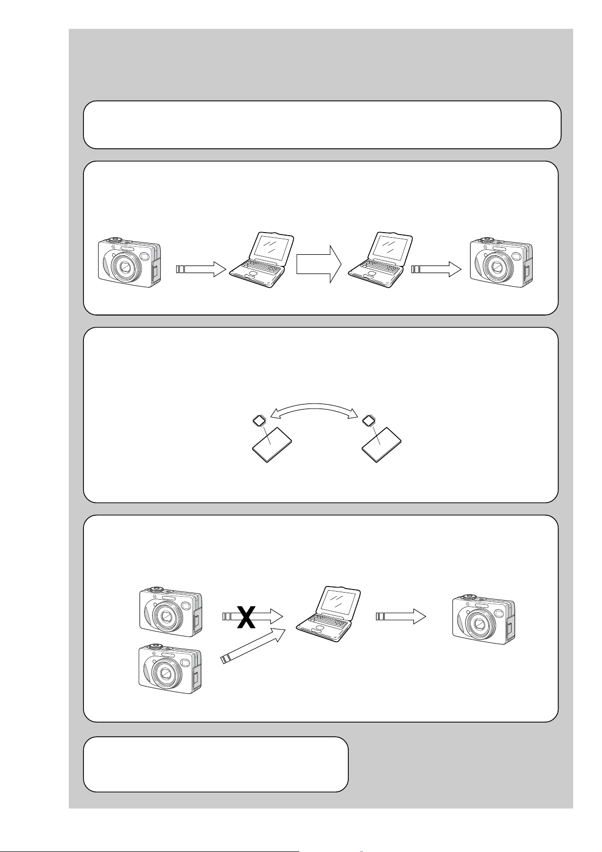
EVR Data Re-writing Procedure When Replacing Board
The data that is stored in the repair board, is not necessarily correct.
Perform either procedure 1 or procedure 2 or procedure 3 when replacing board.
Procedure 1
Save the EVR data of the machine in which a board is going to be replaced. Download the saved data after a
board is replaced.
DSC-W1/W12
SECTION 6
ADJUSTMENTS
(Machine before starting repair)
Save the EVR data
to a personal computer.
Procedure 2
Remove the flash memory from the board of the machine that is going to be repaired. Install the removed flash
memory to the replaced board.
PC
Remove the flash memory and install it.
(Former board)
(New board)
PC
Download the saved
data to a machine.
(Machine after a board is replaced)
Procedure 3
When the data cannot be saved due to defective f lash memory, or when the flash memory cannot be removed or
installed, save the data from the same model of the same destination, and download it.
(Machine to be repaired)
Download the data.
Save the data.
(The same model of the same destination)
After the EVR data is saved and downloaded, check the
respective items of the EVR data.
(Refer to page 6-2 for the items to be checked.)
(Machine to be repaired)PC
6-1
DSC-W1/W12
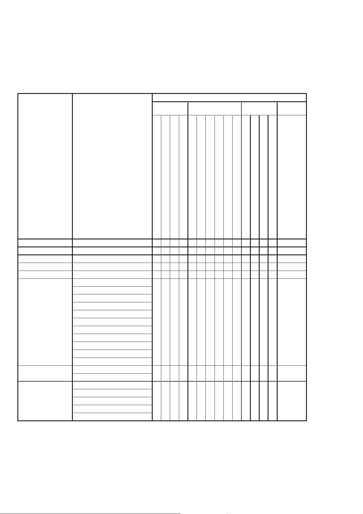
1-1. Adjusting items when replacing main parts and boards
When replacing main parts and boards, adjust the items indicated by z in the following table.
Note 1: The automatic Adjustment Program does not support the “Initialization of data”. Perform it manually.
Note 2: Use the Color Shading Adjustment Program (W1P100ColorShade.exe) when performing “Color Shading Adjustment” of
Camera System Adjustment.
Replaced parts
Block Mounted parts Board
replacement replacement replacement
Flash memory
replacement
Adjusting item Adjustment
(Note 1) Initialization of data
VIDEO adjustment Video output level adj.
CAMERA adjustment 1 Flange back adj.
CAMERA adjustment 2 Flange back check
(Note 2) Color shading adj.
F No. compensation
Mechanical shutter adj.
Light value adj.
AWB 3200K standard data input
AWB 5800K standard data input
CAMERA adjustment 3
CAMERA adjustment 4
LCD adjustment
AWB 5800K check
AWB 3200K check
CCD linearity check
Color reproduction adj.
CCD white defect compensation check
CCD black defect compensation check
Strobe adj.
Auto focus illumination check
LCD initial data input
VCO adj.
Contrast adj.
V-COM adj.
White Balance adj.
LCD unit
Back light unit
(CCD imager)
(AF illumination LED)
(Timing gen., CCD signal process)
(Camera DSP)
(Video amp.)
Lens block
Flash unit
LCD901
D901
LCD block
LCD block
IC101
D101
IC101
CD-507 board
CD-507 board
CH-146 board
(LCD driver)
IC301
IC302
IC801
SY-102 board
SY-102 board
MS-204 board
(COMPLETE)
(COMPLETE)
(COMPLETE)
CD-507 board
CH-146 board
MS-205 board
(Camera system control)
(With built-in flash memory)
(COMPLETE)
SY-102 board
IC501
SY-102 board
zz
zz z z
zz zzz
zz zzz
zzzzzzz
z
zz z
z
zz
z
z
z
z
zz
z
zzzzz
zz
zz
Table 6-1-1
6-2
DSC-W1/W12
6-1. CAMERA SECTION ADJUSTMENTS
1-1. PREPARATIONS BEFORE ADJUSTMENTS
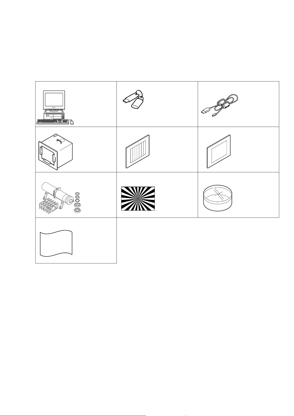
1-1-1. List of Service Tools
• Oscilloscope • Color monitor • Vectorscope • AC power adapter
• Calculating machine capable of calculating hexadecimal numbers.
J-1
J-4
J-10
Personal computer
(Note)
Pattern box PTB-450
J-6082-200-A
or
Small pattern box
PTB-1450
J-6082-557-A
Minipattern box
J-6082-353-B
J-2
HASP key and application
for adjustment (SEUS)
Contact our service headquater of each area
how to get the application for adjustment
(SEUS) and HASP key.
J-5
Color bar chart
For PTB-450:
J-6020-250-A
For PTB-1450:
J-6082-559-A
J-8J-7
Siemens star chart
J-6080-875-A
J-3
USB cable
1-827-038-11
J-6
Clear chart
For PTB-450:
J-6080-621-A
For PTB-1450:
J-6082-560-A
J-9
Filter for color
temperature correction
(C14)
J-6080-058-A
Background paper
J-2501-130-A
Note: Personal computer
OS: Windows98/98SE/Me/2000/XP Home/XP Pro
RAM: 256MB or more recommended
USB: 2.0 recommended (also compatible with 1.1)
Two connectors are required.
Fig. 6-1-1
6-3
DSC-W1/W12
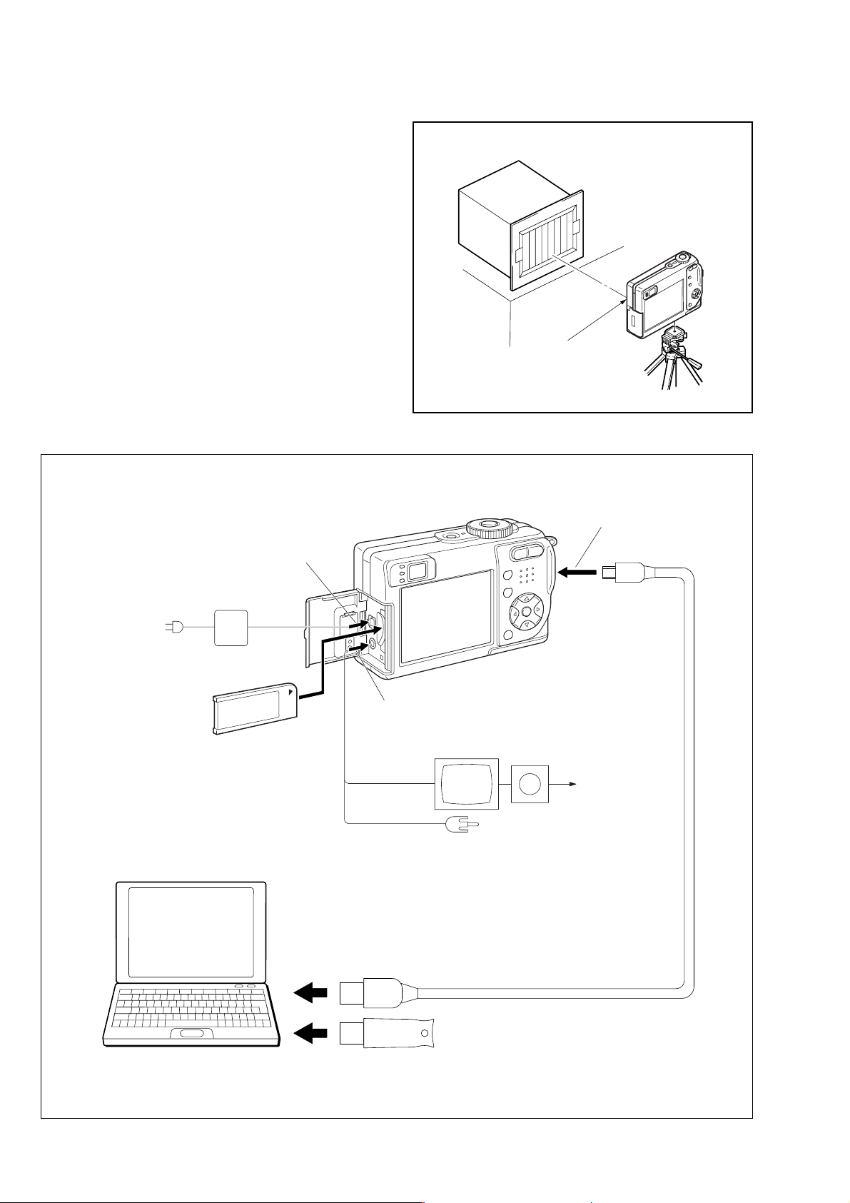
1-1-2. Preparations
1) Connect the equipment for adjustments according to Fig. 6-1-3.
2) Start up the application for adjustment (SEUS).
Pattern box
L
Front of the lens
L = About 27 cm (PTB-450)
L = About 11 cm (PTB-1450)
Fig. 6-1-2
To DC IN jack
AC power adaptor
AC IN
Insert the Memory Stick.
PC
OS: Windows 98/98SE/Me/2000/XP
RAM: 256MB or more recommended
USB: 2.0 recommended (also compatible with 1.1)
Two connectors are required.
To A/V OUT
jack
Video (yellow)
Audio (Black)
Color monitor
To USB
connector
Vectorscope
Terminated
75 Ω
To USB connector
To USB connector
Fig. 6-1-3
USB cable
(1-827-038-11)
HASP Key
6-4
1-1-3. Precautions
1. Setting the Switch
Unless otherwise specified, set the switches as follows and perform adjustments.
1. Mode Dial .......................................... P (Program auto)
2. ZOOM switch
(US-011 flexible S001, S002) ........... WIDE end
3. Video Out (SET UP setting).............. NTSC
4. Digital Zoom (SET UP setting)......... Off
5. EV (Menu items) ............................... 0EV
6. Focus (Menu items) ........................... Multi AF
7. WB (Menu items) .............................. Auto
8. ISO (Menu items) .............................. Auto
9. Flash Level (Menu items).................. Normal
10. P.Effect (Menu items) ........................ Off
11. Saturation (Menu items).................... Normal
12. Contrast (Menu items)....................... Normal
13. Sharpness (Menu items) .................... Normal
DSC-W1/W12
Color bar chart (Standard picture frame)
H
Yellow
Cyan
White
Magenta
Green
BB
A=B/2A
Fig. a
(VIDEO terminal of A/V jack
output waveform)
Red
Blue
A
Enlargement
B
A
Difference in level
2. Subjects
1) Color bar chart (Standard picture frame).
When performing adjustments using the color bar chart, adjust the picture frame as shown in Fig. 6-1-4. (Standard picture frame)
2) Clear chart (Standard picture frame)
Remove the color bar chart from the pattern box and insert a
clear chart in its place. (Do not perform zoom operations during this time)
C=D
V
Fig. 6-1-4
Electronic beam scanning frame
DC
Red
Cyan
White
Green
Yellow
Fig. b (monitor TV picture)
Adjust the camera position and direction to
obtain the output wavefor m shown in Fig a
and the monitor TV display shown in Fig. b.
Blue
Magenta
CRT picture frame
6-5
DSC-W1/W12
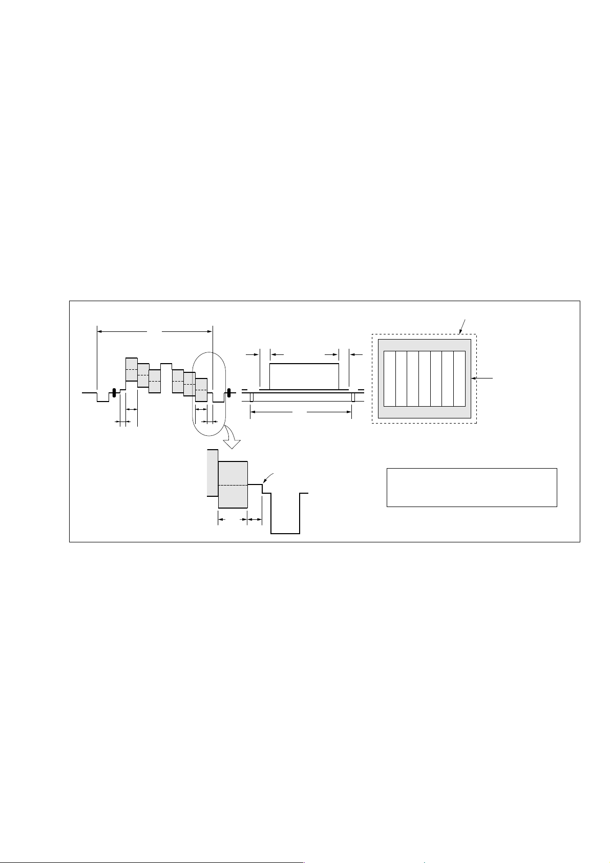
3. Preparing the Flash Adjustment Box
A dark room is required to provide an accurate flash adjustment.
If it is not available, prepare the flash adjustment box as given
below;
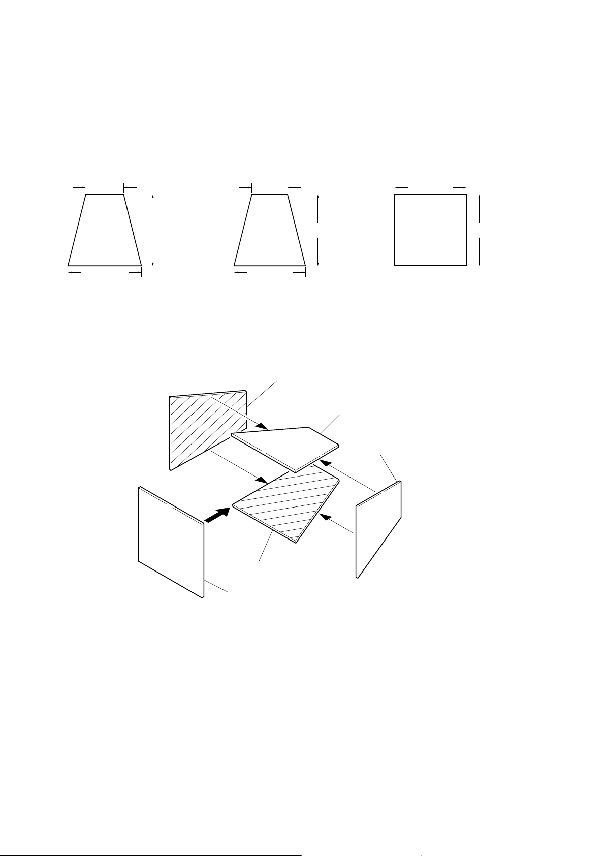
1) Provide woody board A, B and C of 15 mm thickness.
woody board A (2)
400 mm
513 mm 513 mm 700 mm
woody board B (2)
370 mm
700 mm730 mm
Fig. 6-1-5
2) Apply black mat paint to one side of woody board A and B.
3) Attach background paper (J-2501-130-A) to woody board C.
4) Assemble so that the black sides and the background paper
side of woody board A, B and C are internal. (Fig. 6-1-6)
woody board C (1)
700 mm
woody board A
woody board B
woody board A
woody board B
woody board C
Fig. 6-1-6
6-6
DSC-W1/W12
1-1-4. Using Method of SEUS
The application for adjustment (SEUS) is used to change the coefficient for calculating the signal processing or EVR data. The SEUS
performs two-way communication between PC and set through
the USB terminal. The two-way communication result data can be
written to the nonvolatile memory.
1. Connection
1) Connect the HASP key to the USB terminal of the PC.
2) Connect the PC and set with the USB cable.
3) Confirm that the set starts in the USB mode.
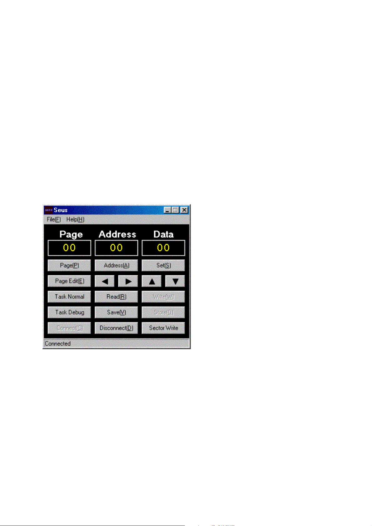
4) Start the SEUS on the PC.
5) Click [Connect] on the SEUS screen. If the connection is normal, the SEUS screen will be as shown in Fig. 6-1-7, indicat-
“connected” state.
ing the
Note: The SEUS will go in
turned off (for instance, by resetting the set). In such a
case, click
“connected” state.
the
[Connect] on the SEUS screen to restore
“disconnect” state, if the set is
2. Operation
•Page change
To change the page, click
the page to be changed. The page is displayed in hexadecimal
notation.
• Address change
To change the address, click [Address] on the SEUS screen and
enter the address to be changed. The address is displayed in
hexadecimal notation.
• Data change
To change the data, click [Set] on the SEUS screen and enter
the data. The data is displayed in hexadecimal notation.
This operation does not write the data to the nonvolatile memory .
•Data saving
To write the all changed data to the nonvolatile memory, click
[Page] on the SEUS screen and enter
[Save] on the SEUS screen and wait for more than 3 sec.
• Data reading
The data displayed on the SEUS screen are the data values at
the time when the pages and addresses were set, and they are
not updated automatically. To check the data change, click
[Read] on the SEUS screen and update the displayed data.
1-1-5. Precaution on Use of SEUS
Wrong SEUS operation could clear correct adjustment data. To
prevent the data clear by mistake, it is recommended to save all
adjustment data by clicking [Page Edit] on the SEUS screen before starting the adjustment.
Fig. 6-1-7
Saving Method:
1) Click [Page Edit] on the SEUS screen to display the SEUS
PAGE EDIT screen.
2) Click [Page], and enter the page number to be saved.
3) Click [Page] to read the data to be saved from the camera.
4) Click [File] and save the data to PC.
Loading Method:
1) Select page: 00, address: 01 and set data: 01.
2) Click [Page Edit] on the SEUS screen to display the SEUS
PAGE EDIT screen.
3) Click [File] and load the data from PC.
4) Click [Write] on the SEUS PAGE EDIT screen.
5) Click [Close] to close the SEUS PAGE EDIT screen.
6) Click [Save] on the SEUS screen.
7) Wait for more than 3 sec.
8) Select page: 80, address: 30, and check that the data is “00”.
9) Select page: 00, address: 01 and set data: 00.
6-7

DSC-W1/W12
1-2. ADJUSTMENT PROGRAMS
The DSC-W1/W12 is adjusted with the Automatic Adjustment Program and the Color Shading Adjustment Program.
The Automatic Adjustment Program automatically controls the
adjustment operations that were formerly entered manually on the
operation screen of the SEUS (some adjustments may be manually operated on the SEUS operation screen).
The Color Shading Adjustment Program automatically performs
“Color Shading Adjustment” of Camera System Adjustment.
1-2-1. Automatic Adjustment Program
1. Precautions When Using Automatic Adjustment
Program
1) The Automatic Adjustment Program writes the adjustment re-
sults such as EVR data to the set through two-way communication with the camera via the SEUS. Accordingly, the Automatic Adjustment Program must be used in the environment
where the SEUS operates.
2) The program run time may vary depending on the environ-
ment of the personal computer used.
3) Even if the Automatic Adjustment Program is used without
starting the SEUS, the SEUS will start automatically when the
adjustment is executed. Howe ver , it may take time for the SEUS
to start, and therefore the Automatic Adjustment Program
should be used with the SEUS started in order to reduce the
program run time.
2. Start of Automatic Adjustment Program
Double-click the application file (DSC-W1_W12 Auto-Adj
Ver_1.[]r
[][]
.exe), and the Automatic Adjustment Program will start.
3. Function of Each Button on Main Menu Screen
When the Automatic Adjustment Program started, the Main Menu
screen in Fig. 6-1-8 will appear. On this screen, select each adjustment section.
1
2
3
4
Fig. 6-1-8
1 [VIDEO SYSTEM ADJUSTMENT] button
The “VIDEO SYSTEM ADJUSTMENT” screen appears.
2 [CAMERA SYSTEM ADJUSTMENT] button
The “CAMERA SYSTEM ADJUSTMENT” screen appears.
3 [LCD SYSTEM ADJUSTMENT] button
The “LCD SYSTEM ADJUSTMENT” screen appears.
4 [END] button
The Automatic Adjustment Program finishes.
Note:[] (numeric value) of the file name v aries depending on the
version of Automatic Adjustment Program.
6-8
 Loading...