

SONY DSC-U20 ADJUSTMENTS
DSC-U20
Ver 1.1 2004. 08
Revision History
Revision History
Link
Link
Before starting adjustments
Before starting adjustments
Adjusting items when replacing main parts and boards
Adjusting items when replacing main parts and boards
CAMERA SECTION ADJUSTMENTS
CAMERA SECTION ADJUSTMENTS
PREPARATIONS BEFORE ADJUSTMENTS
PREPARATIONS BEFORE ADJUSTMENTS
INITIALIZATION OF 2F, 4F, 6F PAGE DATA
INITIALIZATION OF 2F, 4F, 6F PAGE DATA
CAMERA SYSTEM ADJUSTMENTS
CAMERA SYSTEM ADJUSTMENTS
LCD SYSTEM ADJUSTMENTS
LCD SYSTEM ADJUSTMENTS
Contents of LEVEL 2 and LEVEL 3 Service Manual
CONTENTS
1. SERVICE NOTE
2. DISASSEMBLY
3. BLOCK DIAGRAMS
4. PRINTED WIRING BOARDS AND
SCHEMATIC DIAGRAMS
5. REPAIR PARTS LIST
OVERALL
POWER
CD-425 FLEXIBLE,
SL-59 FLEXIBLE,
ST-79, US-4 FLEXIBLE,
OP-17 FLEXIBLE,
SW-376 FLEXIBLE,
RS-85 FLEXIBLE,
FP-532 FLEXIBLE,
FP-533 FLEXIBLE
EXPLODED VIEWS
ELECTRICAL PARTS
SECTION 6
ADJUSTMENTS
LEVEL 2
a
a
SERVICE MODE
SERVICE MODE
APPLICATION FOR ADJUSTMENT (SEUS)
APPLICATION FOR ADJUSTMENT (SEUS)
DATA PROCESS
DATA PROCESS
SERVICE MODE
SERVICE MODE
LEVEL 3
✕
✕
✕
TY-15, PD-174, DD-182
BOARD
✕
a
(DD-182, PD-174, TY-15
BOARD)
ADJ
9-876-212-51
Sony EMCS Co.
2004H0500-1
©2004.8
Published by DI Technical Support Section

DSC-U20
TABLE OF CONTENTS
Section Title Page
6. ADJUSTMENTS
Before Starting Adjustment ·······················································6-1
1-1. Adjusting Items when Replacing
Main Parts and Boards ····················································6-2
6-1. Camera Section Adjustments··········································· 6-3
1-1. Preparations Before Adjustments ····································6-3
1-1-1.List of Service Tools ························································6-3
1-1-2.Preparations ·····································································6-4
1-1-3.Precautions ······································································6-5
1. Setting the Switch····························································6-5
2. Order of Adjustments ······················································ 6-5
3. Subjects ···········································································6-5
4. Preparing the Flash Adjustment Box·······························6-6
1-2. Initialization of 2F, 4F, 6F Page Data······························ 6-7
1-2-1.Initialization of 2F, 4F, 6F Page Data······························ 6-7
1. Initializing of 2F, 4F, 6F Page Data·································6-7
2. 2F Page Table ··································································6-7
3. 4F Page Table ··································································6-7
4. 6F Page Table ··································································6-8
1-3. Camera System Adjustments·········································6-10
Data Setting During Camera System Adjustments········6-10
Picture Frame setting····················································· 6-10
1. HALL Adjustment ·························································6-11
2. Flange Back Adjustment ···············································6-12
2-1. Flange Back Adjustment ···············································6-12
2-2. Flange Back Check························································6-12
3. F No. Compensation······················································ 6-13
4. Mechanical Shutter Adjustment ···································· 6-13
5. Light V alue Adjustment················································· 6-14
6. Mixed Color Cancel Data Input & Check ·····················6-14
7. AWB 3200K Standard Data Input ································· 6-15
8. AWB 3200K Check ·······················································6-15
9. AWB 5800K Standard Data Input ································· 6-16
10. AWB 5800K Check ·······················································6-17
11. Color Reproduction Data Input & Check······················ 6-18
12. CCD Linearity Check ····················································6-19
13. Strobe Adjustment ························································· 6-21
1-4. LCD System Adjustments ·············································6-22
Data Setting During LCD System Adjustments············6-22
1. LCD Initial Data Input (1)············································· 6-22
2. LCD Initial Data Input (2)············································· 6-23
3. VG Center Adjustment ··················································6-24
4. Bright Adjustment ·························································6-25
5. Contrast Adjustment ······················································6-26
6. PSIG Adjustment ···························································6-27
7. V -COM Adjustment······················································· 6-28
8. White Balance Adjustment············································6-29
8-1. White Balance Adjustment (VR)···································6-29
8-2. White Balance Adjustment (VB)···································6-30
6-2. Service Mode·································································6-31
2-1. Application for Adjustment (SEUS)······························ 6-31
2-1-1.Using Method of SEUS ·················································6-31
1. Connection·····································································6-31
2. Operation ·······································································6-31
2-1-2.Precaution on Use of SEUS···········································6-31
2-2. Data Process ··································································6-32
2-3. Service Mode·································································6-32
1. Setting the Test Mode ···················································· 6-32
2. Bit V alue Discrimination ···············································6-33
3. Switch Check (1) ···························································6-33
4. Switch Check (2) ···························································6-34
5. LED Check ····································································6-34
6. Self Diagnosis Code ······················································ 6-34
— 2 —
COVER
COVER
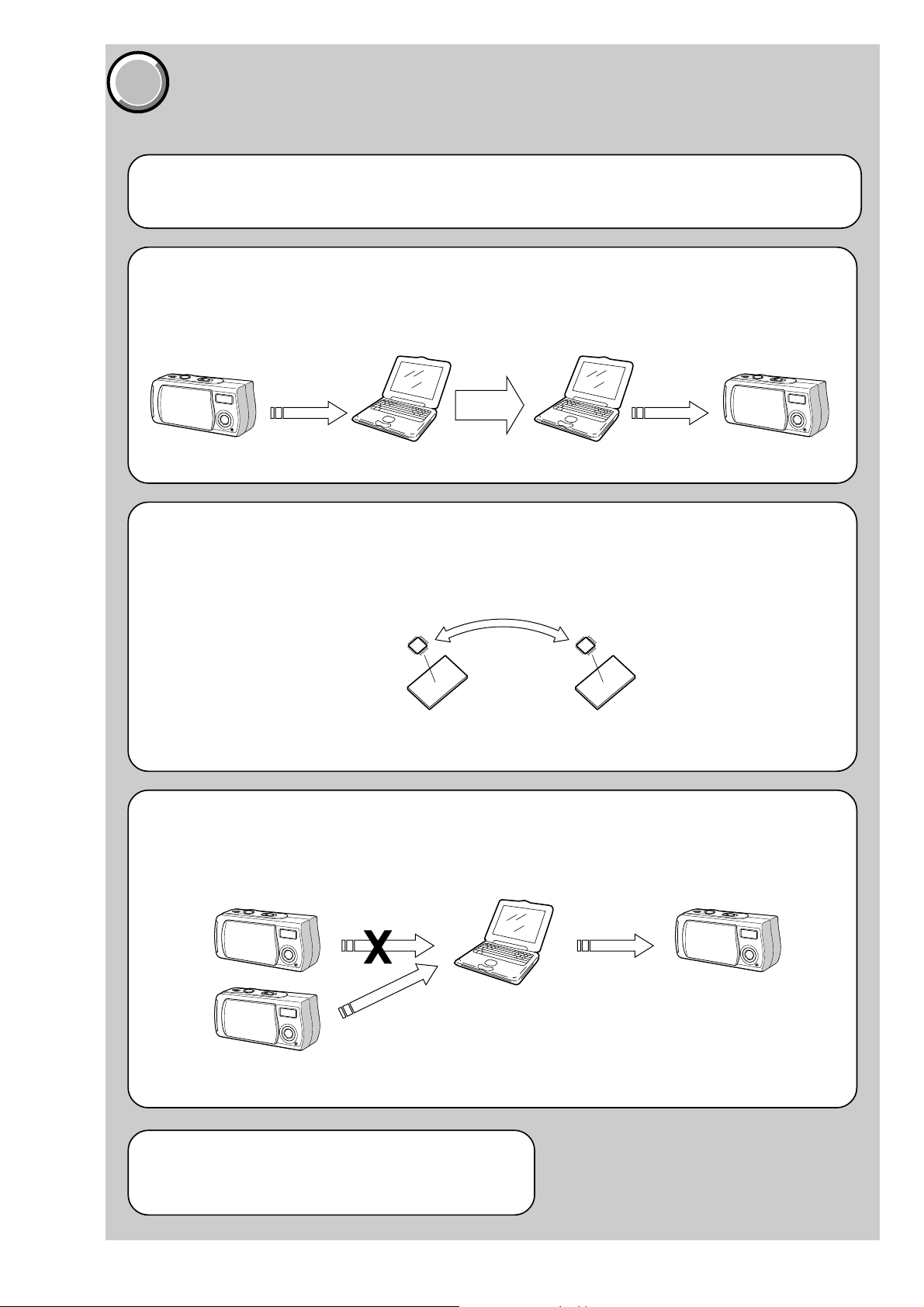
Before starting adjustment
EVR Data Re-writing Procedure When Replacing Board
The data that is stored in the repair board, is not necessarily correct.
Perform either procedure 1 or procedure 2 or procedure 3 when replacing board.
Procedure 1
Save the EVR data of the machine in which a board is going to be replaced. Download the saved data after a
board is replaced.
DSC-U20
SECTION 6
ADJUSTMENTS
(Machine before starting repair)
Save the EVR data
to a personal computer.
Procedure 2
Remove the EEPROM from the board of the machine tha t is going to be repaired. Install the removed EEPR OM
to the replaced board.
PC
Remove the EEPROM and install it.
(Former board)
(New board)
PC
Download the saved
data to a machine.
(Machine after a board is replaced)
Procedure 3
When the data cannot be saved due to defective EEPROM, or when the EEPROM cannot be removed or installed, save the data from the same model of the same destination, and download it.
(Machine to be repaired)
Download the data.
Save the data.
(The same model of the same destination)
After the EVR data is saved and downloaded, check the
respective items of the EVR data.
(Refer to page 6-2 for the items to be checked.)
(Machine to be repaired)PC
6-1
DSC-U20
COVER
COVER
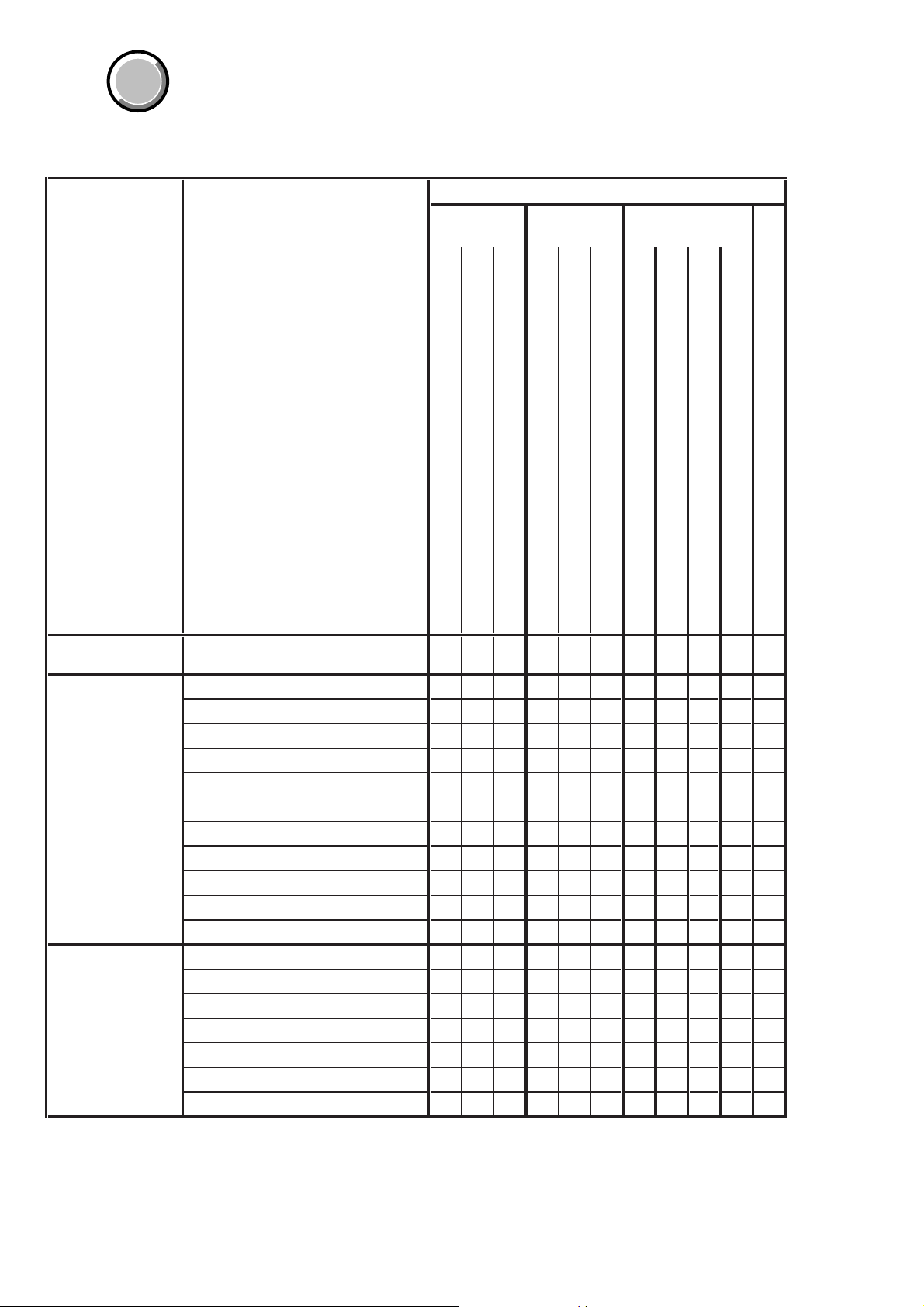
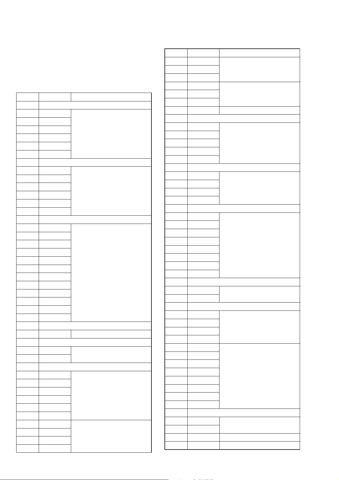
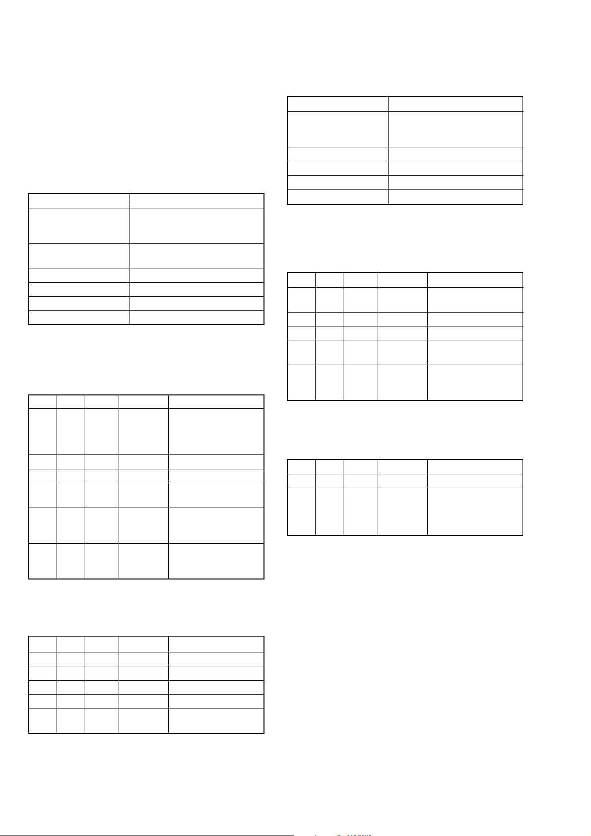
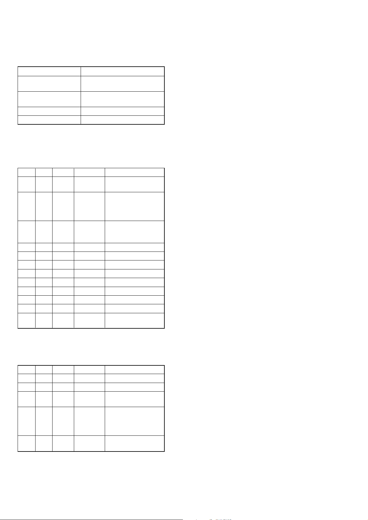
1-1. Adjusting items when replacing main parts and boards
When replacing main parts and boards, adjust the items indicated by z in the following table.
Block Mounted parts Board
replacement replacement replacement
Replaced parts
Adjustment section Adjustment
Lens block assy
Initialization of 2F,
4F, 6F, page data
Camera Hall adj. zzz
LCD LCD initial data input zz
Initialization of 2F, 4F, 6F page data zz
Flange back adj. zz zz
F No. compensation zz zz
Mechanical shutter adj. zz zz
Light value adj. zzzzz
Mixed color cancel data input & check zzzzz
AWB 3200K standard data input zzzzz
AWB 5800K standard data input zzzzz
Color reproduction data input & check zzzzz
CCD linearity check zzzzz
Strobe adj. zz zzz z
VG center adj. zzzzz
Bright adj. zzzzz
Contrast adj. zzzzz
PSIG adj. zzzzz
V-COM adj. zzzzz
White balance adj. zzzzz
(LCD panel)
LCD901
Flash unit
LCD block
(CCD imager)
(Camera DSP)
(LCD drive)
IC302
IC602
IC401
CD-425 board
TY-15 board
PD-174 board
(COMPLETE)
(COMPLETE)
(COMPLETE)
CD-425 board
TY-15 board
SL-59 flexible board
EEPROM
(COMPLETE)
IC604
PD-174 board
TY-15 board
Table 6-1-1
6-2
COVER
COVER
6-1. CAMERA SECTION ADJUSTMENTS
1-1. PREPARATIONS BEFORE ADJUSTMENTS
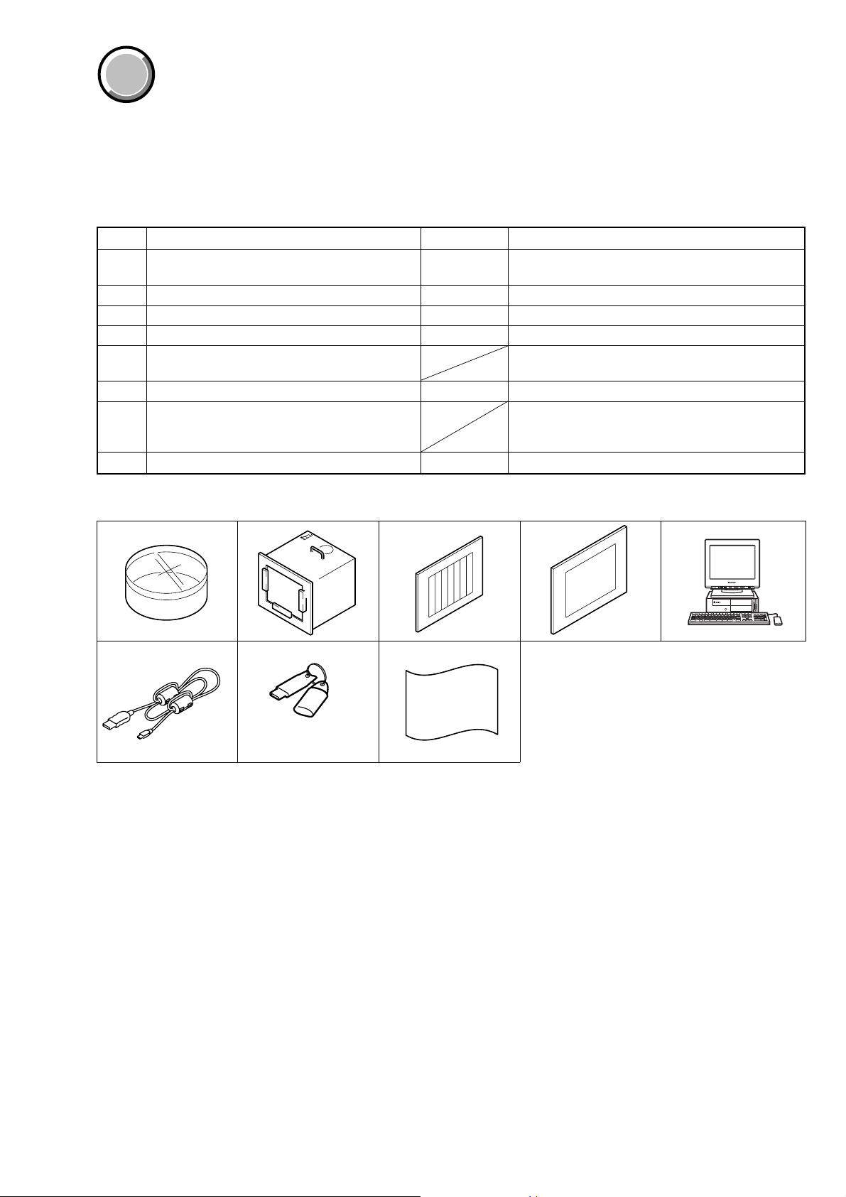
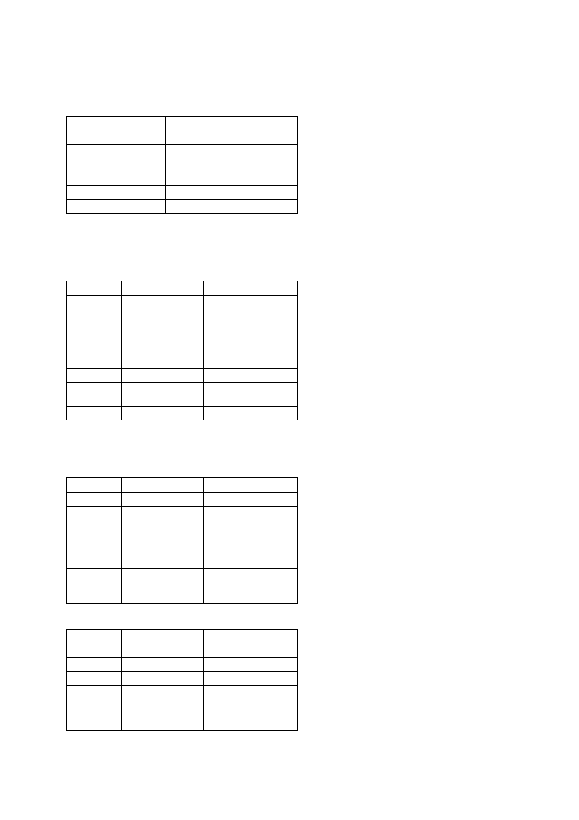
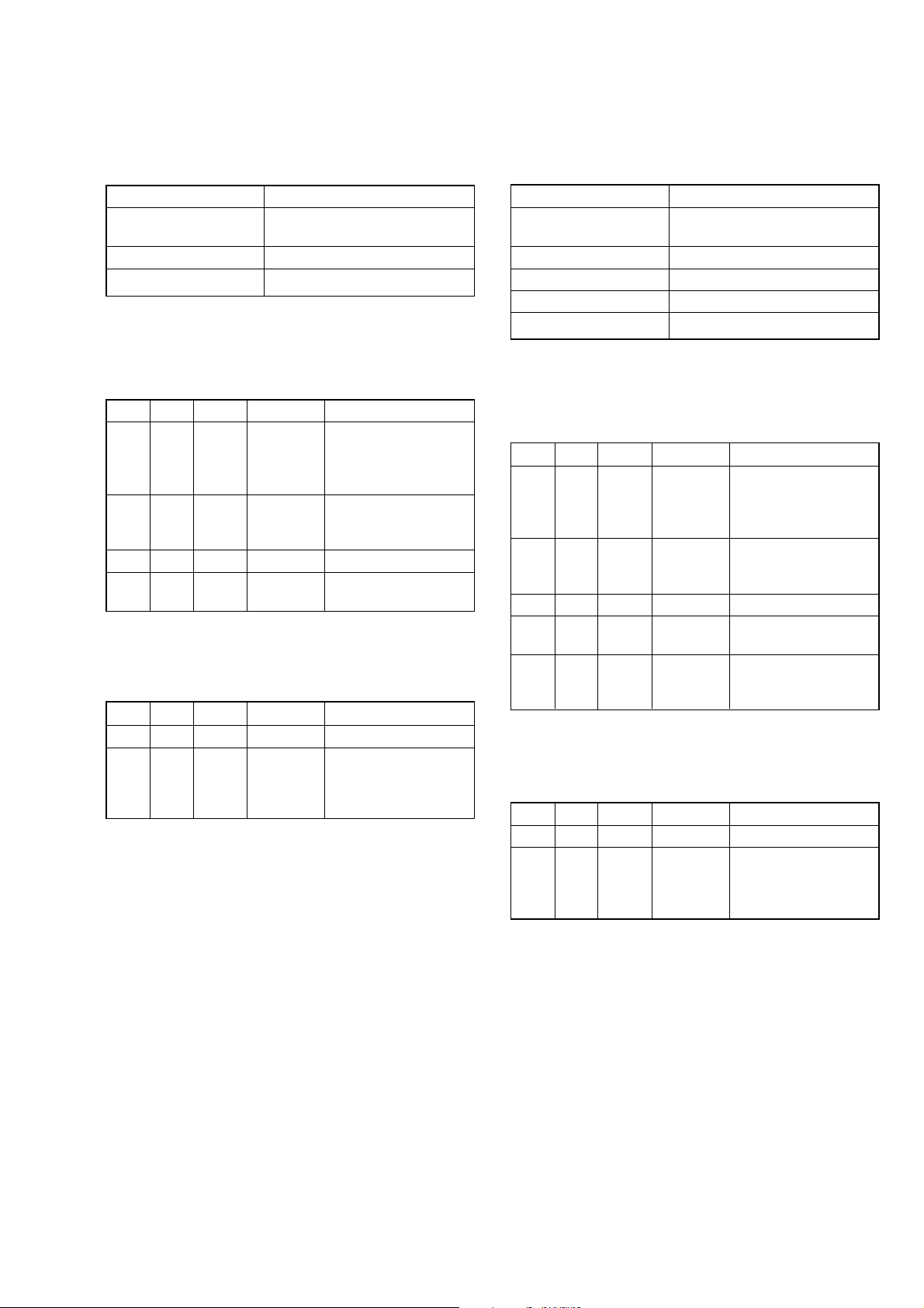
1-1-1. List of Service Tools
• Calculating machine capable of calculating hexadecimal numbers.
Ref. No. Name Parts Code Usage
J-1 Filter for color temperature correction (C14) J-6080-058-A
J-2 Pattern box PTB-450 J-6082-200-A
J-3 Color bar chart for pattern box J-6020-250-A
J-4 Clear chart for pattern box J-6080-621-A
J-5 Parsonal computer
J-6 USB cable 1-823-932-11 For connecting the camera to PC
HASP key and application for adjustment
J-7
(SEUS)
J-8 Background paper J-2501-130-A For adjusting the strobe
Auto white balance adjustment/check
White balance adjustment/check
OS: Windows 98/98SE/Me/2000/XP Home/XP Pro
USB connector × 2
Contact our service headquarter of each area how to
get the application for adjustment (SEUS) and HASP
key
DSC-U20
J-1 J-5J-2
J-6 J-7
J-3 J-4
J-8
and application for
adjustment (SEUS)
Fig. 6-1-1
6-3
DSC-U20
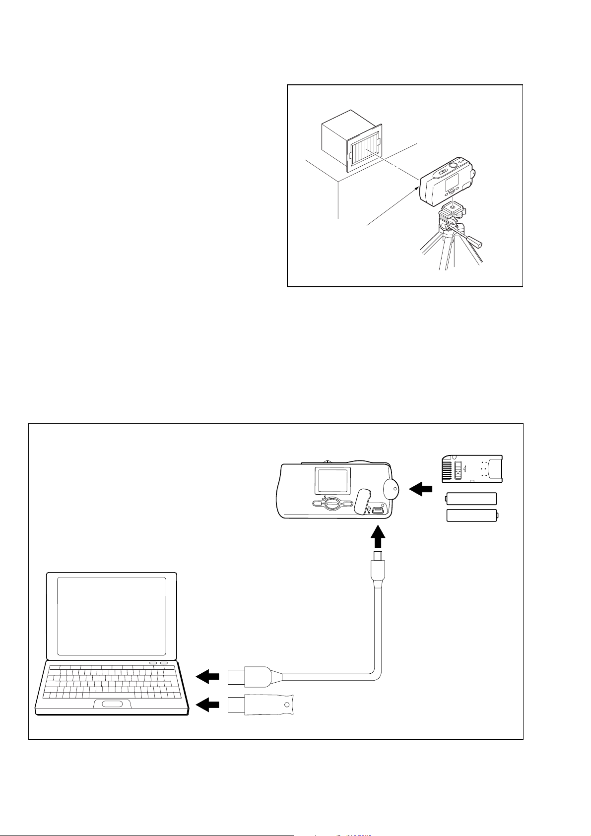
1-1-2. Preparations
1) Connect the equipment for adjustments according to Fig. 6-1-3.
2) Start up the application for adjustment (SEUS).
Note 1: Setting the “F orced CAMERA mode po wer ON Mode”
1) Select page: 00, address: 01, and set data: 01.
2) Select page: 2F, address: 11, and write data: E0.
3) Select page: 2F, address: 12, and write data: BC.
4) Select page: 20, address: 00, and set data: 29.
5) Select page: 20, address: 01, and write data: 29.
At this time, the set is reset and the power is turns
off once and then on again. Accordingly, the message “Receive Packet Error” is displayed on the
SEUS screen, and the SEUS goes in “disconnect”
state, but this is not a trouble. Click [Connect] on
the SEUS screen to restore the “connected” state.
6) Select page: 00, address: 01, and set data: 01.
7) Select page: 2F, address: 21, and write data: 02.
The above procedure will enable the camera power to
be turned on. After completing adjustments, be sure to
exit the “Forced CAMERA mode power ON Mode”.
Pattern box
L
Front of the lens
L = About 30 cm
Fig. 6-1-2
Note 2: Exiting the “F orced CAMERA mode po wer ON Mode”
1) Select page: 00, address: 01, and set data: 01.
2) Select page: 2F, address: 21, and write data: 00.
3) Select page: 2F, address: 12, and write data: 2C.
4) Select page: 2F, address: 11, and write data: 60.
5) Select page: 00, address: 01, and set data: 00.
PC
with USB connectors (x 2)
(Windows 98/98SE/ME/2000/XP)
DSC-U20
To USB connector
Insert the Memory Stick
and the Batteries*.
LOCK
*:Size AAA
Nickel Metal Hydride
batteries (x 2)
To USB connector
To USB connector
Fig. 6-1-3
USB cable
(1-823-932-11)
HASP Key
6-4
1-1-3. Precautions
1. Setting the Switch
Unless otherwise specified, set the switches as follows and perform adjustments.
1. FOCUS (Menu setting)...................... AUTO
2. P.EFFECT (Menu setting) ................. OFF
3. USB (Menu setting)........................... NORMAL
2. Order of Adjustments
Basically carry out adjustments in the order given.
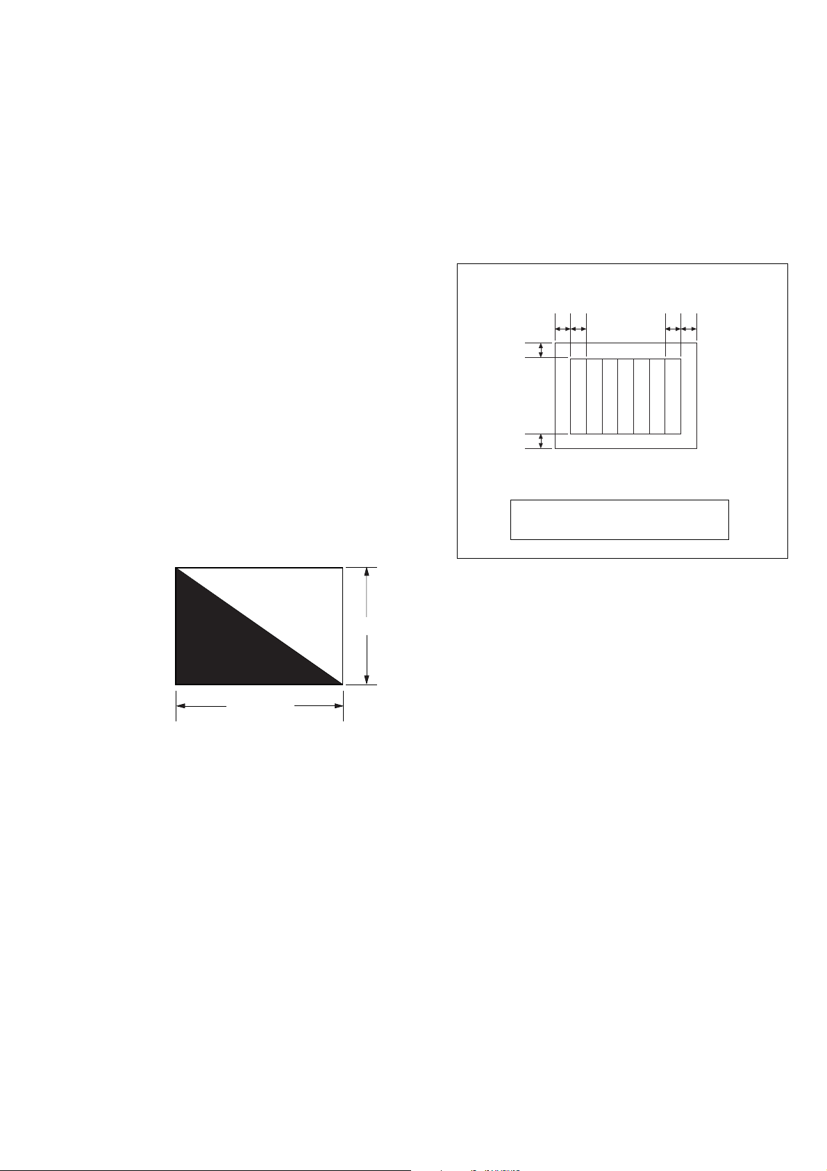
3. Subjects
1) Color bar chart (Standard picture frame).
When performing adjustments using the color bar chart, adjust the picture frame as shown in Fig. 6-1-4. (Standard picture frame)
2) Clear chart (Standard picture frame)
Remove the color bar chart from the pattern box and insert a
clear chart in its place.
3) Chart for flange back adjustment
Join together a piece of white A0 size paper (1189mm × 841
mm) and a piece of black paper to make the chart shown in
Fig. 6-1-5.
Note: Use a non-reflecting and non-glazing vellum paper. The
size must be A0 or larger and the joint between the white
and black paper must not have any undulations.
DSC-U20
Color bar chart (Standard picture frame)
AB
C
C=D
D
Fig. (Picture on LCD screen)
Adjust the camera direction to obtain the
picture on LCD screen shown in Fig.
A=B
Yellow
Cyan
Green
White
Magenta
BA
Red
Blue
Black
Fig. 6-1-4
White
841 mm
1189 mm
Fig. 6-1-5
6-5
DSC-U20
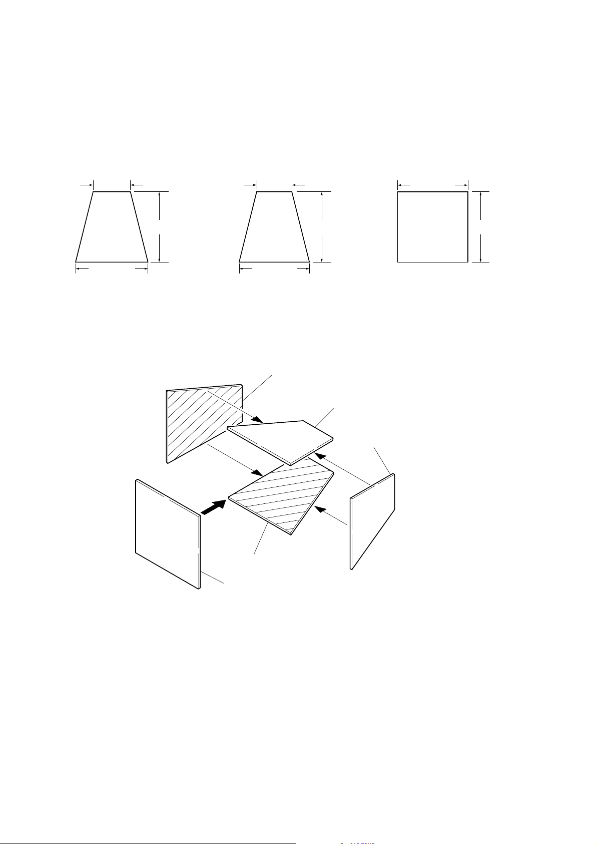
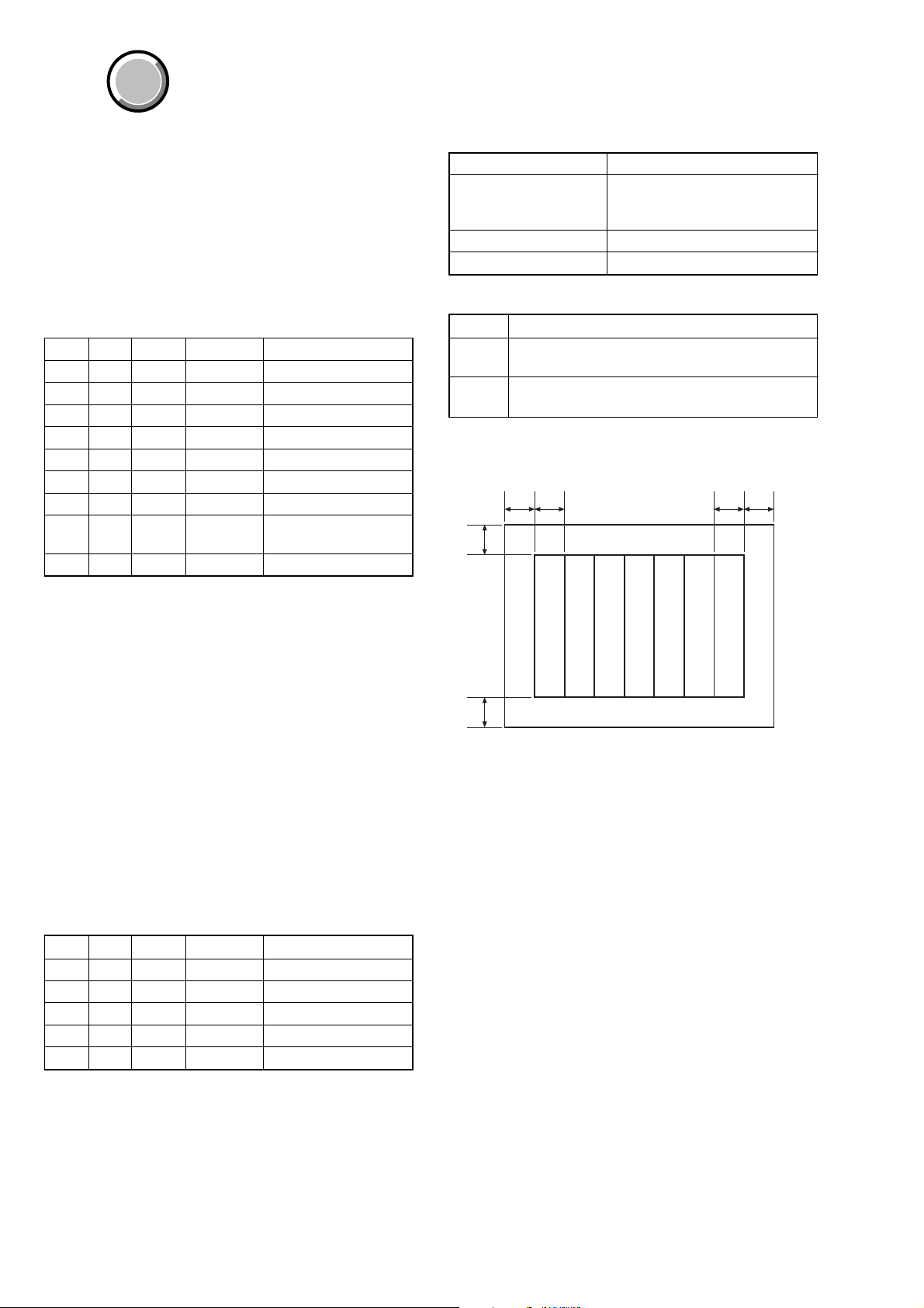
4. Preparing the Flash Adjustment Box
A dark room is required to provide an accurate flash adjustment.
If it is not available, prepare the flash adjustment box as given
below;
1) Provide woody board A, B and C of 15 mm thickness.
woody board A (2)
400 mm
513 mm 513 mm 700 mm
woody board B (2)
Fig. 6-1-6
2) Apply black mat paint to one side of woody board A and B.
3) Attach background paper (J-2501-130-A) to woody board C.
4) Assemble so that the black sides and the background paper
side of woody board A, B and C are internal. (Fig. 6-1-7)
370 mm
700 mm730 mm
woody board A
woody board C (1)
700 mm
woody board B
woody board A
woody board B
woody board C
Fig. 6-1-7
6-6
COVER
COVER
DSC-U20
1-2. INITIALIZATION OF 2F, 4F, 6F PA GE D ATA
1-2-1. Initialization of 2F, 4F, 6F Page Data
1. Initializing of 2F, 4F, 6F Page Data
Note 1: Initialize the data every page of 2F, 4F, and 6F.
Note 2: If the 4F page data has been initialized, the following
adjustments need to be performed again.
1) LCD system adjustments
Note 3: If the 6F page data has been initialized, the following
adjustments need to be performed again.
1) Camera system adjustments
Adjusting Page 2F
Adjusting Address 10 to 73
Adjusting Page 4F
Adjusting Address 00 to FF
Adjusting Page 6F
Adjusting Address 00 to FF
Initializing Method:
1) Click
2) Click [Page], and then enter the page to be initialized.
3) Click [Preset Data Read] to display the Set ID input screen.
4) Enter Set ID = “3” and read the initializing data on the SEUS
5) On the SEUS PAGE EDIT screen, change the data at “Fixed
6) Confirm that the data at respective adjustment addresses are
7) Click [Write] to write the initializing data to the set.
8) Click [Close] to close the SEUS PAGE EDIT screen.
Processing after Completing Initializing
Order Page
[Page Edit] on the SEUS screen to display the SEUS
PAGE EDIT screen.
PAGE EDIT screen.
data-2” address given in the table on the page to be initialized.
Note: New data for change are not listed in the table. If the
data are to be changed, read and copy the data from the
same model. Copying the data from different models
may cause an operation failure.
the initial values (adjustment initial values) gi v en in the table.
If different, change to the adjustment initial values.
Address
16F0020 [Write]
2200029 [set]
3200129 [Write] (Note)
Data Procedure
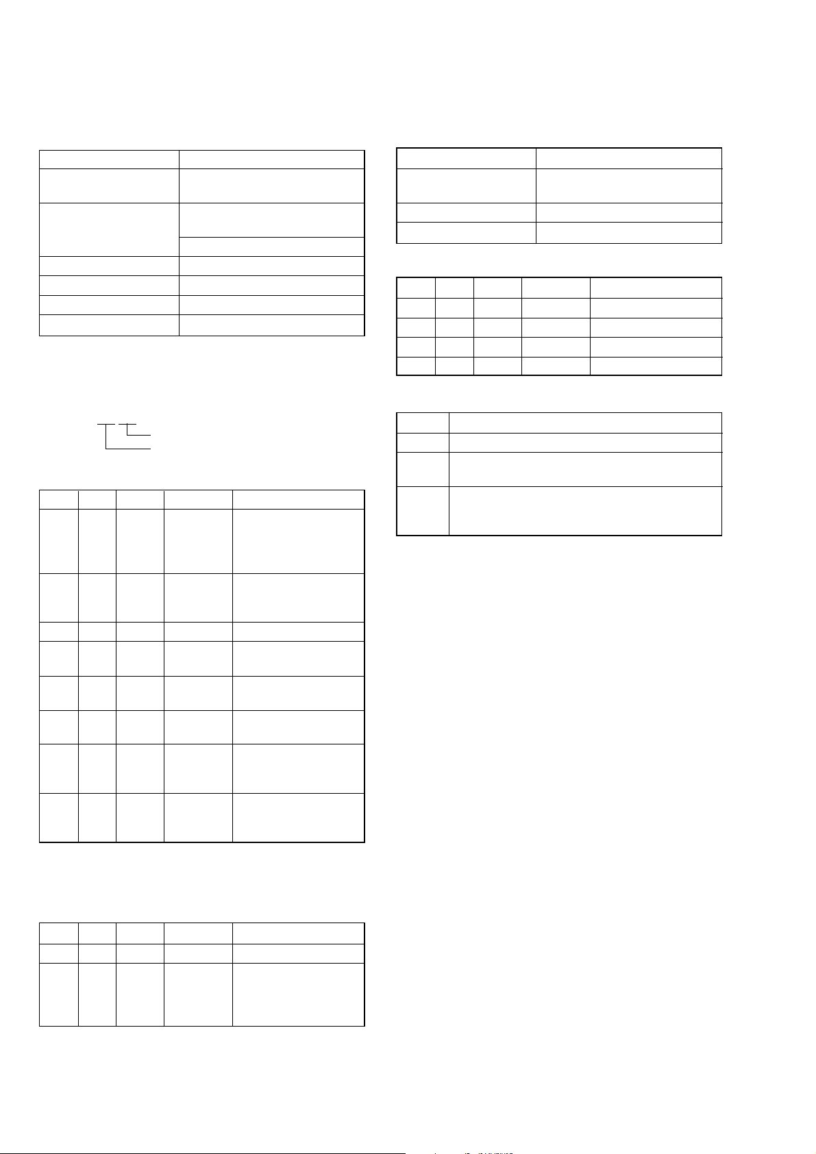
2. 2F Page table
Note 1: Fixed data-1: Initialized data.
(Refer to step 4 of “1. Initializing of 2F, 4F, 6F Page
Data”)
Note 2: Fixed data-2: Modified data.
(Refer to step 5 of “1. Initializing of 2F, 4F, 6F Page
Data”)
Address Initial value Remark
10 to 20 Fixed data-1 (Initialized data)
21 00 Test mode
22 to 73 Fixed data-1 (Initialized data)
3. 4F Page table
Note 1: Fixed data-1: Initialized data.
(Refer to step 4 of “1. Initializing of 2F, 4F, 6F Page
Data”)
Note 2: Fixed data-2: Modified data.
(Refer to step 5 of “1. Initializing of 2F, 4F, 6F Page
Data”)
Address Initial value Remark
00 to 1F Fixed data-1 (Initialized data)
20 Fixed data-2
21 to 81 Fixed data-1 (Initialized data)
82 95 V-COM adj. (LCD)
83 BF Bright adj. (LCD)
84 Fixed data-1 (Initialized data)
85 38 PSIG adj. (LCD)
86 8C
87 80
88 5A Contrast adj. (LCD)
89 33 VG center adj. (LCD)
8A Fixed data-2
8B to FF Fixed data-1 (Initialized data)
White balance adj. (LCD)
Note: At this time, the set is reset and the power is turns off once
and then on again. Accordingly, the message “Receive
Packet Error” is displayed on the SEUS screen, and the
SEUS goes in “disconnect” state, but this is not a trouble.
Click
[Connect] on the SEUS screen to restore the “con-
nected” state.
6-7
DSC-U20
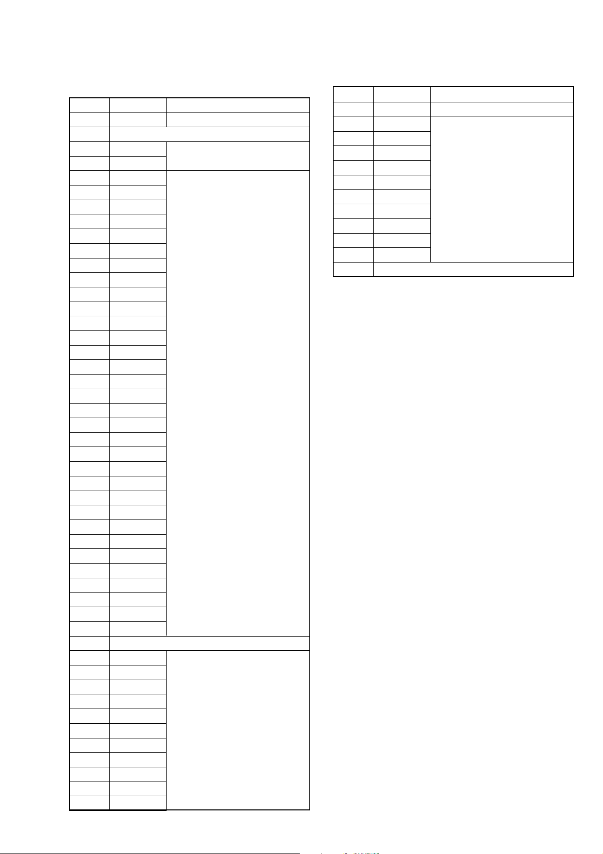
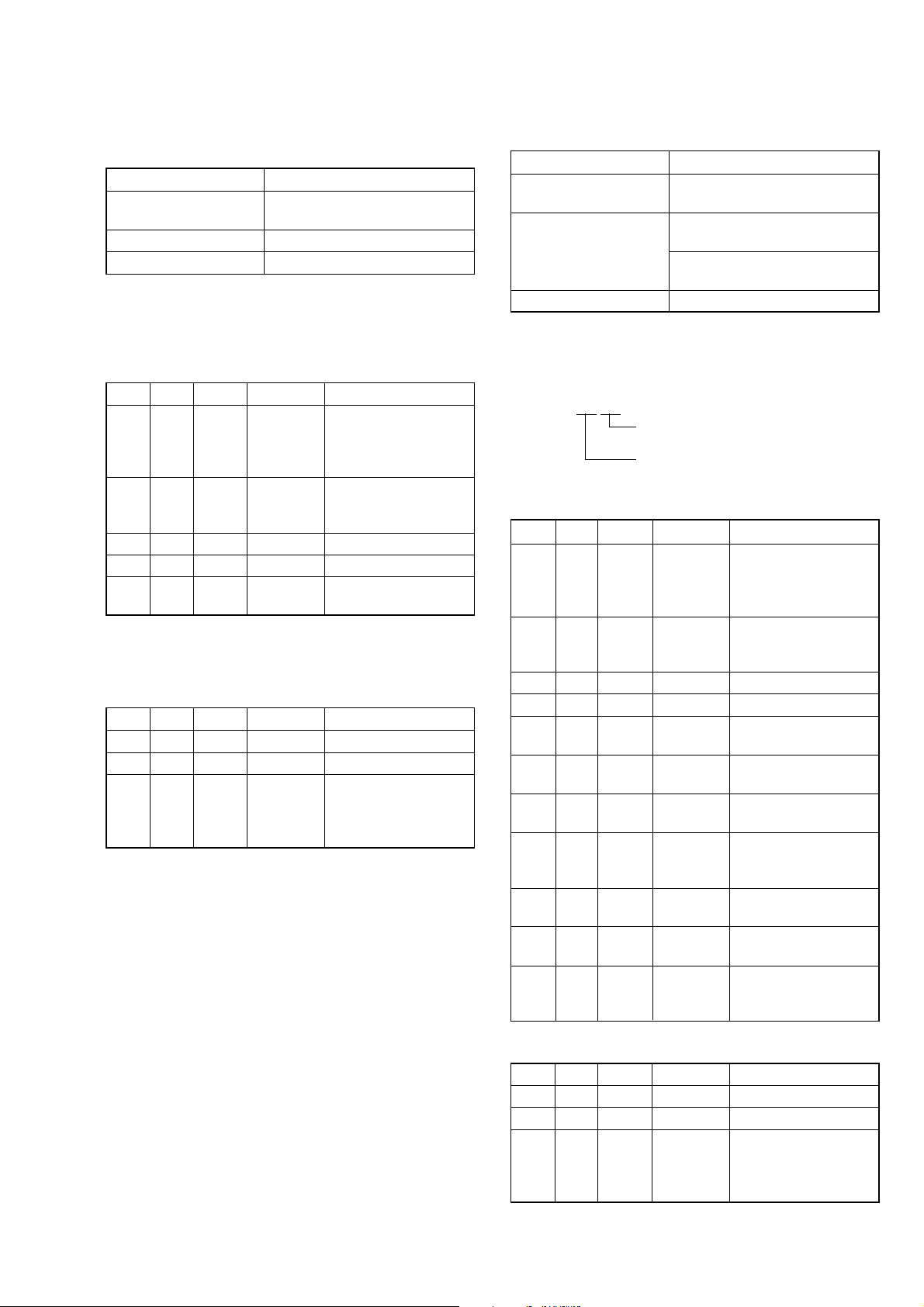
4. 6F Page table
Note 1: Fixed data-1: Initialized data.
(Refer to step 4 of “1. Initializing of 2F, 4F, 6F Page
Data”)
Note 2: Fixed data-2: Modified data.
(Refer to step 5 of “1. Initializing of 2F, 4F, 6F Page
Data”)
Address Initial value Remark
00 to 0F Fixed data-1 (Initialized data)
10 10
11 00
12 10
13 00
14 00
15 FF
16, 17 Fixed data-1 (Initialized data)
18 10
19 00
1A 10
1B 00
1C 10
1D 1D
1E, 1F Fixed data-1 (Initialized data)
20 00
21 00
22 00
23 00
24 20
25 20 Flange back adj.
26 00
27 02
28 02
29 00
2A 00
2B 00
2C to 3D Fixed data-1 (Initialized data)
3E FF Flange back adj.
3F to 51 Fixed data-1 (Initialized data)
52 00
53 00
54 to 57 Fixed data-1 (Initialized data)
58 44
59 A9
5A 15
5B 5B
5C 79
5D 5D
5E 13
5F 42
60 08
61 00
Flange back check
Flange back adj.
Flange back adj.
Hall adj.
F No. compensation
Address Initial value Remark
62 00
63 00 F No. compensation
64 00
65 3E
66 00 Light value adj.
67 A3
68 10 Hall adj.
69 to 6F Fixed data-1 (Initialized data)
70 2F
71 81
72 1F AWB 3200K standard data input
73 81
74 2F
75 to 7B Fixed data-1 (Initialized data)
7C 1D
7D 01
7E 31
7F 01
80 to 87 Fixed data-1 (Initialized data)
88 00
89 00
8A 00
8B 00
8C 00
8D 00
8E 00
8F 00
90 to 99 Fixed data-1 (Initialized data)
9A 00
9B 00
9C to 9F Fixed data-1 (Initialized data)
A0 2A
A1 00
A2 60
A3 00
A4 F4
A5 F1
A6 6A
A7 88
A8 FC
A9 FF
AA 7A
AB 6C
AC to AF Fixed data-1 (Initialized data)
B0 00
B1 00
B2 00 AWB 3200K standard data input
B3 00 AWB 5800K standard data input
AWB 5800K standard data input
CCD linearity check
CCD linearity check
AWB 5800K standard data input
Color reproduction data input & check
Mixed color cancel data input & check
6-8
DSC-U20
6F Page table
Address Initial value Remark
B4 00 AWB 3200K standard data input
B5 Fixed data-1 (Initialized data)
B6 28
B7 6E
B8 09
B9 39
BA 06
BB 6A
BC 06
BD 03
BE 00
BF 00
C0 00
C1 00
C2 00
C3 00
C4 00
C5 00
C6 00
C7 44 Mechanical shutter adj.
C8 5B
C9 69
CA 00
CB 00
CC 80
CD 88
CE 98
CF 90
D0 88
D1 00
D2 00
D3 00
D4 00
D5 00
D6 00
D7 14
D8 to D9 Fixed data-1 (Initialized data)
DA 00
DB 00
DC 00
DD 00
DE 00
DF 00 Strobe adj.
E0 00
E1 00
E2 00
E3 00
E4 00
Strobe adj.
Address Initial value Remark
E5 00
E6 00
E7 00
E8 00
E9 00
EA 00 Strobe adj.
EB 00
EC 00
ED 00
EE 00
EF 00
F0 to FF Fixed data-1 (Initialized data)
6-9
DSC-U20
COVER
COVER
1-3. CAMERA SYSTEM ADJUSTMENTS
Data Setting During Camera System Adjustments
Perform the following data setting before the camera system adjustments.
It is not necessary to perform the following data setting ev ery time
when you perform some item of camera system adjustment continuously unless the power is turned off. Only when the power is
turned off during this adjustments, perform the data setting again,
then continue the adjustment.
Data setting method:
Order Page
1000101 [Set]
22F11E0 [Write]
32F12BC [Write]
4200029 [set]
5200129 [Write] (Note)
6000101 [Set]
72F2102 [Write]
860E1[Read]
94F020C
Address
Data Procedure
Check the data changes
to “02”.
[Write]
Picture Frame Setting
Mode CAMERA
Subject Color bar chart
(Standard picture frame)
(30 cm from the front of lens)
Measurement Point Picture on LCD screen
Specified value A=B, C=D
Setting method:
Order Procedure
Adjust the camera direction, and set the specified
1
position.
Adjust the picture frame to this position in following
2
adjustment using “Standard picture frame”.
Check on LCD screen
AB
C
A=B
BA
Note: At this time, the set is reset and the power is turns off once
and then on again. Accordingly, the message “Receive
Packet Error” is displayed on the SEUS screen, and the
SEUS goes in “disconnect” state, but this is not a trouble.
Click [Connect] on the SEUS screen to restore the “connected” state.
After completing the camera system adjustments, release the
data setting:
1) Click [Page Edit] on the SEUS screen to display the SEUS
PAGE EDIT screen.
2) Click [Page], and then enter the page “0E”.
3) Click [Preset Data Read] to display the Set ID input screen.
4) Enter Set ID = “3” and read the initializing data on the SEUS
PAGE EDIT screen.
5) Check that all the data is “FF”.
6) Click [Write] to write the initializing data to the set.
7) Click [Close] to close the SEUS PAGE EDIT screen.
8) Release the data setting which has been executed before adjustment.
Order Page
14F0200 [Write]
22F2100 [Write]
32F122C [Write]
42F1160 [Write]
5000100 [Set]
Address
Data Procedure
C=D
D
Yellow
Cyan
Green
White
Magenta
Red
Blue
Fig. 6-1-8
6-10
1. HALL Adjustment
For detecting the position of lens iris, adjust the hall AMP gain
and offset.
Mode CAMERA
Subject Not required
Measurement Point Data of page: 10, address: 06
Adjustment Page 6F
Adjustment Address 58 to 5D and 68
Specified value 1 12 to 1A
Specified value 2 80 to 88
Note 1: Check that the data of page: 60, address: 02 is “00”. If
not, press the RESET switch at the bottom of the set using a thin and long pin.
Adjusting method:
Order Page
1
2609416 [Write]
3609584 [Write]
460016D [Write] (Note 2)
56002
6600100
Address
Data Procedure
Perform “Data setting
during camera system
adjustment”
(Refer to page 6-10)
[Read]
Check the data changes
to “01”.
[Write]
DSC-U20
Note 2: The adjustment data will be automatically input to page:
6F, address: 58 to 5D and 68.
Checking method:
Order Page
1600101 [Write]
21006[Read]
3600100 [Write]
4600103 [Write]
51006[Read]
Processing after Completing Adjustment:
Order Page
1600100 [Write]
2609400 [Write]
3609500 [Write]
4
Address
Address
Data Procedure
Check that the data
satisfied the specified
value 1.
Check that the data
satisfied the specified
value 2.
Data Procedure
Release “Data setting
during camera system
adjustment”
(Refer to page 6-10)
6-11
DSC-U20
2. Flange Back Adjustment
The inner focus lens flange back adjustment is carried out automatically. In whichever case, the focus will be deviated during
auto focusing/manual focusing.
Preparations before adjustments:
1) Check that the center of Flange back adjustment chart meets
the center of shot image screen.
2-1. Flange Back Adjustment
Mode CAMERA
Subject Flange back adjustment chart
(2.0 m from the front of lens)
(Luminance: 300 to 400 lux)
Measurement Point Data of page: 6F, address: 24 and
3E
Adjustment Page 6F
Adjustment Address 18 to 1D, 20 to 2B, 3E, 52 and 53
Specified value 1 00
Specified value 2 0A to 7F
Note 1: Check that the data of page: 60, address: 02 is “00”. If
not, press the RESET switch at the bottom of the set using a thin and long pin.
Adjusting method:
Order Page
1
2600113 [Write]
3600115 [Write] (Note 2)
46002
56F3E
66F24
Address
Data Procedure
Perform “Data setting
during camera system
adjustment”
(Refer to page 6-10)
[Read]
[Read]
[Read]
Check the data changes
to “01”.
Check that the data
satisfied the specified
value 1.
Check that the data
satisfied the specified
value 2.
2-2. Flange Back Check
Mode CAMERA
Subject Flange back adjustment chart
(2.0 m from the front of lens)
(Luminance: 300 to 400 lux)
Measurement Point Data of page: 6F, address: 15
Adjustment Page 6F
Adjustment Address 10 to 15
Specified value 00
Note 1: Check that the data of page: 60, address: 02 is “00”. If
not, press the RESET switch at the bottom of the set using a thin and long pin.
Checking method:
Order Page
1
2000101 [Set]
36001DD [Write] (Note 2)
46002
56F15
Note 2: The adjustment data will be automatically input to page:
Processing after Completing Adjustment:
Order Page
1600100 [Write]
2
Address
[Read]
[Read]
6F, address: 10 to 15.
Address
Data Procedure
“Flange Back Adjustment” is completed.
Check the data changes
to “01”.
Check that the data
satisfied the specified
value.
Data Procedure
Release “Data setting
during camera system
adjustment”
(Refer to page 6-10)
Note 2: The adjustment data will be automatically input to page:
6F, address: 18 to 1D, 20 to 2B, 3E, 52 and 53.
Processing after Completing Adjustment:
Order Page
1600100 [Write]
2200029 [Set]
3200129 [Write] (Note 3)
4Wait for 4 seconds.
5
Note 3: At this time, the set is reset and the power is turns off
Address
once and then on again. Accordingly, the message “Receive Packet Error” is displayed on the SEUS screen, and
the SEUS goes in “disconnect” state, but this is not a
trouble. Click [Connect] on the SEUS screen to restore
the “connected” state.
Data Procedure
Perform “Flange Back
Check”.
6-12
DSC-U20
3. F No. Compensation
Adjust the dispersion of the lens iris every F number , and compensate the exposure.
Mode CAMERA
Subject Clear chart
(Standard picture frame)
Adjustment Page 6F
Adjustment Address 5E to 64
Note 1: Check that the data of page: 60, address: 02 is “00”. If
not, press the RESET switch at the bottom of the set using a thin and long pin.
Adjusting method:
Order Page
1
2
36001BB [Write] (Note 2)
46002
Note 2: The adjustment data will be automatically input to page:
Processing after Completing Adjustment:
Order Page
1600100 [Write]
2 Release “Data setting
Address
[Read]
6F, address: 5E to 64.
Address
Data Procedure
Perform “Data setting
during camera system
adjustment”
(Refer to page 6-10)
Perform “Picture frame
setting”
(Refer to page 6-10)
Check the data changes
to “01”.
Data Procedure
during camera system
adjustment”
(Refer to page 6-10)
4. Mechanical Shutter Adjustment
Adjust the close time and loss time every F number of mechanical
shutter, and compensate the exposure.
Mode CAMERA
Subject Clear chart
(Standard picture frame)
Measurement Point Data of page: 60, address: AB
Adjustment Page 6F
Adjustment Address B8 to D7
Specified value 00
Note 1: Check that the data of page: 60, address: 02 is “00”. If
not, press the RESET switch at the bottom of the set using a thin and long pin.
Adjusting method:
Order Page
1
2
36001AD [Write] (Note 2)
46002
560AB
Note 2: The adjustment data will be automatically input to page:
Processing after Completing Adjustment:
Order Page
1600100 [Write]
2
Address
Data Procedure
[Read]
[Read]
6F, address: B8 to D7.
Address
Data Procedure
Perform “Data setting
during camera system
adjustment”
(Refer to page 6-10)
Perform “Picture frame
setting”
(Refer to page 6-10)
Check the data changes
to “01”.
Check that the data
satisfied the specified
value.
Release “Data setting
during camera system
adjustment”
(Refer to page 6-10)
6-13
DSC-U20
5. Light V alue Adjustment
Adjust the standard light value.
Mode CAMERA
Subject Clear chart
(Standard picture frame)
Measurement Point Data of page: 10, address: 0C and
0D (2byte data) (Note 2)
Data of page: 6F, address: 65
Adjustment Page 6F
Adjustment Address 65 to 67
Specified value 1 0FE0 to 1020
Specified value 2 38 to 48
Note 1: Check that the data of page: 60, address: 02 is “00”. If
not, press the RESET switch at the bottom of the set using a thin and long pin.
Note 2: 2byte data is upper 1byte data and lower 1byte data.
XX XX
Lower 1byte data (Page: 10, address: 0D)
Upper 1byte data (Page: 10, address: 0C)
Adjusting method:
Order Page
1
2
360010D [Write] (Note 3)
46002
5100C
6100D
7
86F65
Address
Data Procedure
Perform “Data setting
during camera system
adjustment”
(Refer to page 6-10)
Perform “Picture frame
setting”
(Refer to page 6-10)
[Read]
[Read]
[Read]
[Read]
Check the data changes
to “01”.
Read the data
(Upper 1byte).
Read the data
(Lower 1byte).
Check that the 2byte
data (Note 2) satisfied
the specified value 1.
Check that the data
satisfied the specified
value 2.
6. Mixed Color Cancel Data Input & Check
Correct the dispersion of Gr/Gb filter on CCD imager
Mode CAMERA
Subject Color bar chart
(Standard picture frame)
Adjustment Page 6F
Adjustment Address B0 and B1
Input method:
Order Page
1000101 [Set]
26FB000 [Write]
36FB132 [Write]
4000100 [Set]
Checking method:
Order Procedure
1 Shoot the color bar chart.
2
3
Address
Capture the shot picture into the PC, and display the
picture on the PC screen.
Confirm that no line (horizontal streak) is present in
blue, red and magenta portions of the picture of color
bar chart displayed.
Data Procedure
Note 3: The adjustment data will be automatically input to page:
6F, address: 65 to 67.
Processing after Completing Adjustment:
Order Page
1600100 [Write]
2
Address
Data Procedure
Release “Data setting
during camera system
adjustment”
(Refer to page 6-10)
6-14
DSC-U20
7. AWB 3200K Standard Data Input
Adjust the white balance reference at 3200K.
Mode CAMERA
Subject Clear chart
(Standard picture frame)
Adjustment Page 6F
Adjustment Address 70 to 74, B2 and B4
Note 1: Check that the data of page: 60, address: 02 is “00”. If
not, press the RESET switch at the bottom of the set using a thin and long pin.
Adjusting method:
Order Page
1
2
3603702 [Set]
460010B [Write] (Note 2)
56002
Note 2: The adjustment data will be automatically input to page:
Processing after Completing Adjustment:
Order Page
1600100 [Write]
2603700 [Set]
3
Address
6F, address: 70 to 74, B2 and B4.
Address
Data Procedure
Perform “Data setting
during camera system
adjustment”
(Refer to page 6-10)
Perform “Picture frame
setting”
(Refer to page 6-10)
[Read]
Data Procedure
Check the data changes
to “01”.
Release “Data setting
during camera system
adjustment”
(Refer to page 6-10)
8. AWB 3200K Check
Mode CAMERA
Subject Clear chart
(Standard picture frame)
Measurement Point Data of page: 10, address: 08 and
09 (2byte data) (Note 2)
Data of page: 10, address: 0A and
0B (2byte data) (Note 2)
Specified value 3F60 to 40A0
Note 1: Check that the data of page: 60, address: 02 is “00”. If
not, press the RESET switch at the bottom of the set using a thin and long pin.
Note 2: 2byte data is upper 1byte data and lower 1byte data.
XX XX
Lower 1byte data
(Page: 10, address: 09 or 0B)
Upper 1byte data
(Page: 10, address: 08 or 0A)
Checking method:
Order Page
1
2
360370E [Set]
460010F [Write]
56002[Read]
61008
71009
8
9100A
10 10 0B
11
Address
Data Procedure
Perform “Data setting
during camera system
adjustment”
(Refer to page 6-10)
Perform “Picture frame
setting”
(Refer to page 6-10)
Check the data changes
to “01”.
[Read]
[Read]
[Read]
[Read]
Read the data
(Upper 1byte).
Read the data
(Lower 1byte).
Check that the 2byte
data (Note 2) satisfied
the specified value.
Read the data
(Upper 1byte).
Read the data
(Lower 1byte).
Check that the 2byte
data (Note 2) satisfied
the specified value.
Processing after Completing Adjustment:
Order Page
1600100 [Write]
2603700 [Set]
3
Address
Data Procedure
6-15
Release “Data setting
during camera system
adjustment”
(Refer to page 6-10)
DSC-U20
9. AWB 5800K Standard Data Input
Adjust the white balance reference at 5800K.
Mode CAMERA
Filter Filter C14 for color temperature
correction
Subject Clear chart
(Standard picture frame)
Adjustment Page 6F
Adjustment Address 7C to 7F, A0 to A3 and B3
Note 1: Check that the data of page: 60, address: 02 is “00”. If
not, press the RESET switch at the bottom of the set using a thin and long pin.
Adjusting method:
Order Page
1
2
3
46FA028 [Write]
56FA100 [Write]
66FA260 [Write]
76FA300 [Write]
8796E[Read] Note down the data.
9796E80 [Write]
10 60 37 08 [Set]
11 60 01 A5 [Write] (Note 2)
12 60 02
Address
Data Procedure
Place the C14 filter on
the lens.
Perform “Data setting
during camera system
adjustment”
(Refer to page 6-10)
Perform “Picture frame
setting”
(Refer to page 6-10)
[Read]
Check the data changes
to “01”.
Note 2: The adjustment data will be automatically input to page:
6F, address: 7C to 7F, A0 to A3 and B3.
Processing after Completing Adjustment:
Order Page
1600100 [Write]
2603700 [Set]
3796E[Write]
4
5
Address
Data Procedure
Write the data noted
down at step 8.
Release “Data setting
during camera system
adjustment”
(Refer to page 6-10)
Remove the C14 filter
on the lens.
6-16
 Loading...