

Page 1
DSC-T20/T25
Ver. 1.0 2007.03
Revision History
Revision History
Link
Link
Before starting adjustments
Adjusting items when replacing main parts and boards
List of service tools
CAMERA SECTION ADJUSTMENTS
PREPARATIONS BEFORE ADJUSTMENTS
ADJUSTMENT PROGRAM
DESTINATION DATA WRITE
USB SERIAL No. INPUT
VIDEO SYSTEM ADJUSTMENTS
SECTION 6
ADJUSTMENTS
SERVICE MODE
APPLICATION FOR ADJUSTMENT (SeusEX)
SERVICE MODE
DATA BACKUP
Auto-ADJ
CAMERA SYSTEM ADJUSTMENTS
LCD SYSTEM ADJUSTMENTS
ERROR
•Use this Service Manual together with the Automatic Adjustment Program (DSC-T20_T25 Auto-Adj V er_1.0r01.ex e).
DSC-T20/T25_ADJ
9-852-195-51
Sony EMCS Co.
2007C0500-1
© 2007.3
Published by Kohda TEC
Page 2

TABLE OF CONTENTS
Section Title Page
6. ADJUSTMENTS
Before Starting Adjustments ·····················································6-1
1-1. Adjusting Items When Replacing
Main Parts and Boards ····················································6-3
1-2. List of Service Tools ························································6-4
6-1. Camera Section Adjustments···········································6-6
1-1. Preparations Before Adjustments ····································6-6
1-2. Adjustment Program······················································6-13
1-3. Destination Data Write ··················································6-15
1-4. USB Serial No. Input·····················································6-17
1-5. Video System Adjustments············································6-18
1-6. Camera System Adjustments·········································6-21
1-7. LCD System Adjustments ·············································6-32
1-8. Error···············································································6-34
6-2. Service Mode·································································6-36
2-1. Application for Adjustment (SeusEX) ··························6-36
2-2. Service Mode·································································6-37
2-3. Data Backup ··································································6-42
DSC-T20/T25_ADJ
— 2 —
Page 3

SECTION 6
ADJUSTMENTS
Before starting adjustments
Method for Copying or Erasing the Data in Internal Memory
(Internal Memory/Music)
The data can be copied/erased by the operations on the HOME screen. (When erasing the data, execute formatting the
internal memory.)
Note 1: When replacing the SY-170 board, erase the data in internal memory of the board before replacement.
Note 2: When replacing the SY-170 board, execute formatting and initialize the internal memory after replace-
ment.
Method for copying the data in internal memory
Copy
Copies all images in the internal memory to a “Memory Stick Duo”.
1 Insert a “Memory Stick Duo” having 32MB or larger capacity.
2 Select [Copy] with v/V/b/B on the control button, then press z.
The message
3 Select [OK] with v, then press z.
Copying starts.
To cancel the copying
Select [Cancel] in step 3, then press z.
• Use a fully charged battery pack. If you attempt to copy image files using a battery pack with little
remaining charge, the battery pack may run out, causing copying to fail or possibly corrupting the data.
• You cannot copy individual images.
• The original images in the internal memory are retained even after copying. To delete the contents of the
internal memory, remove the “Memory Stick Duo” after copying, then execute the [Format] command in
[ Internal Memory Tool].
• When you copy the data in the internal memory to the “Memory Stick Duo”, all the data will be copied.
You cannot choose a specific folder on the “Memory Stick Duo” as the destination for the data to be
copied.
• Even if you copy data, a DPOF (Print order) mark is not copied.
“All data in internal memory will be copied” appears.
Method for formatting the internal memory
This item does not appear when a “Memory Stick Duo” is inserted in the camera.
Format
Formats the internal memory.
• Note that formatting irrevocably erases all data in the internal memory, including even protected images.
1 Select [Format] with v/V/b/B on the control button, then press z.
The message “All data in internal memory will be erased” appears.
2 Select [OK] with v, then press z.
The format is complete.
To cancel the formatting
Select [Cancel] in step 2, then press z.
DSC-T20/T25_ADJ
6-1
Page 4
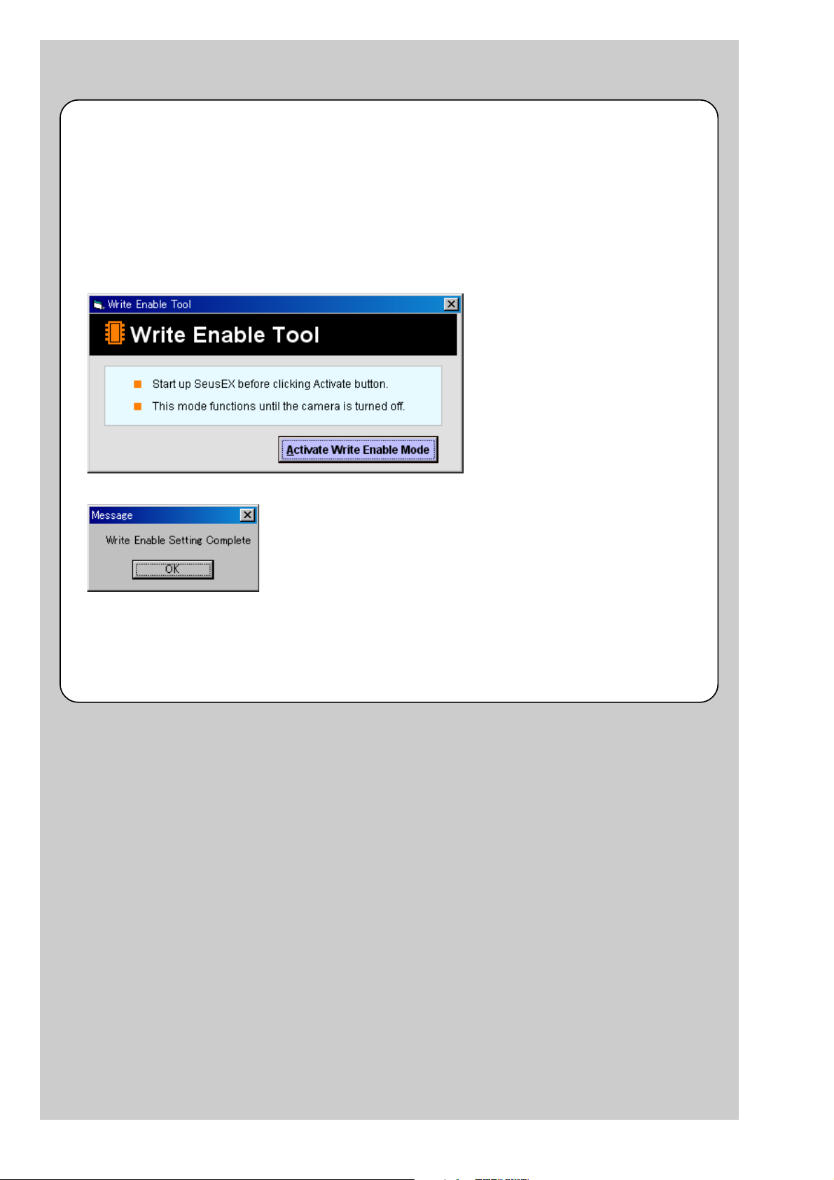
How to Write Data to Internal Memory
Usually, the camera has been set so as to disable the data writing from the PC to the internal memory of the camera.
This setting must be changed temporarily when the data is to be written to the internal memory such as a case after the
board replacement.
To change the setting, use the write enable tool “WriteEnableTool.exe”.
Data writing method
1) Connect the PC to the camera (USB mode: Mass Storage), and switch the driver to the “Sony Seus USB Driver”.
2) Start the Write Enable Tool and the SeusEX.
3) Click the [Activate Write Enable Mode] button of the Write Enable Tool.
4) Upon completion of the setting change, the following message will be displayed.
5) Return the driver to the original one, and connect the PC to the camera (USB mode: Mass Storage).
6) Write the data read out into the PC to the internal memory of the camera.
7) Disconnect the PC from the camera, and turn off the camera.
Note: By turning off the camera, the write enable setting is reset.
DSC-T20/T25_ADJ
6-2
Page 5
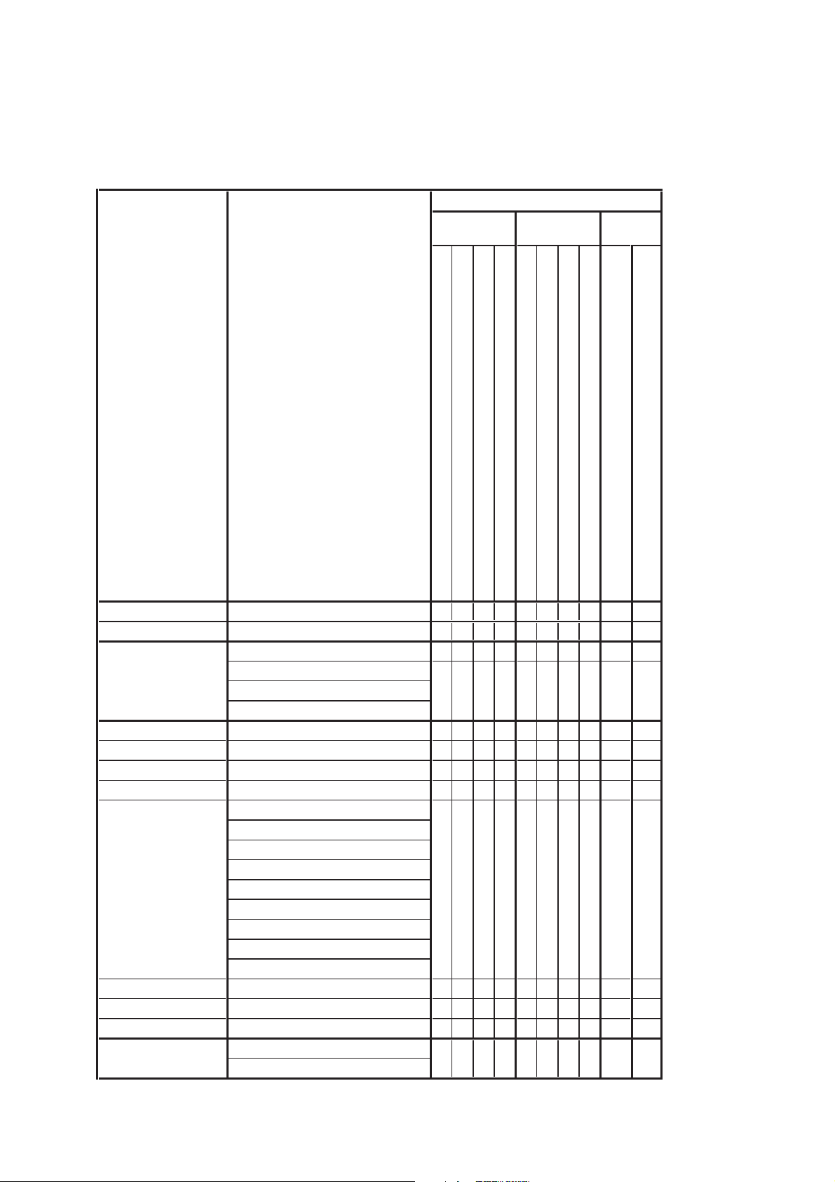
1-1. Adjusting items when replacing main parts and boards
When replacing main parts and boards, adjust the items indicated by z in the following table.
Note 1: The automatic Adjustment Program does not support the “Wide Limit Adjustment”. Perform it manually.
Note 2: When replacing the SY-170 board, erase the data in internal memory of the board before replacement.
Note 3: When replacing the SY-170 board, execute formatting and initialize the internal memory after replacement.
Replaced parts
Block Mounted parts Board
replacement replacement replacement
Adjusting item Adjustment
Destination Data Write Destination data write
USB Serial No. Input USB serial No. input
Composite video level adj.
VIDEO adjustment
CAMERA adjustment 1 Hall adj.
(Note 1) Wide limit adj.
CAMERA adjustment 2 Flange back adj.
CAMERA adjustment 3 Flange back check
CAMERA adjustment 4
CAMERA adjustment 5 Strobe adj.
CAMERA adjustment 6 Auto focus illumination check
CAMERA adjustment 7 Angular velocity sensor sensitivity adj.
LCD adjustment
Component out Y level adj.
Component out Pb level adj.
Component out Pr level adj.
F No. compensation
Measure gain, LV adj.
Mechanical shutter adj.
AWB 3200K-5800K standard data input
AWB 3200K-5800K check
Color reproduction adj. & check
CCD linearity check
CCD white defect compensation check
CCD black defect compensation check
V-COM adj.
White Balance adj.
LCD unit
(AF illumination LED)
(Timing gen., CCD signal process)
(Audio, Video amp.)
(PITCH, YAW sensor)
LCD901
D002
IC304
IC602
SE502, SE501
(COMPLETE)
(COMPLETE) (Note 2, 3)
Lens block
CCD block assy (Including CD-695 flexible board and CCD imager)
Flash unit
LCD block
ST-163 board
SY-170 board
SY-170 board
SY-170 board
ST-163 board
SY-170 board
z
z
zz
zz
zz
zz
zz z
zz z
zz z
z
zz z z z
zzz
zzz
z
z
DSC-T20/T25_ADJ
Table 6-1-1
6-3
Page 6
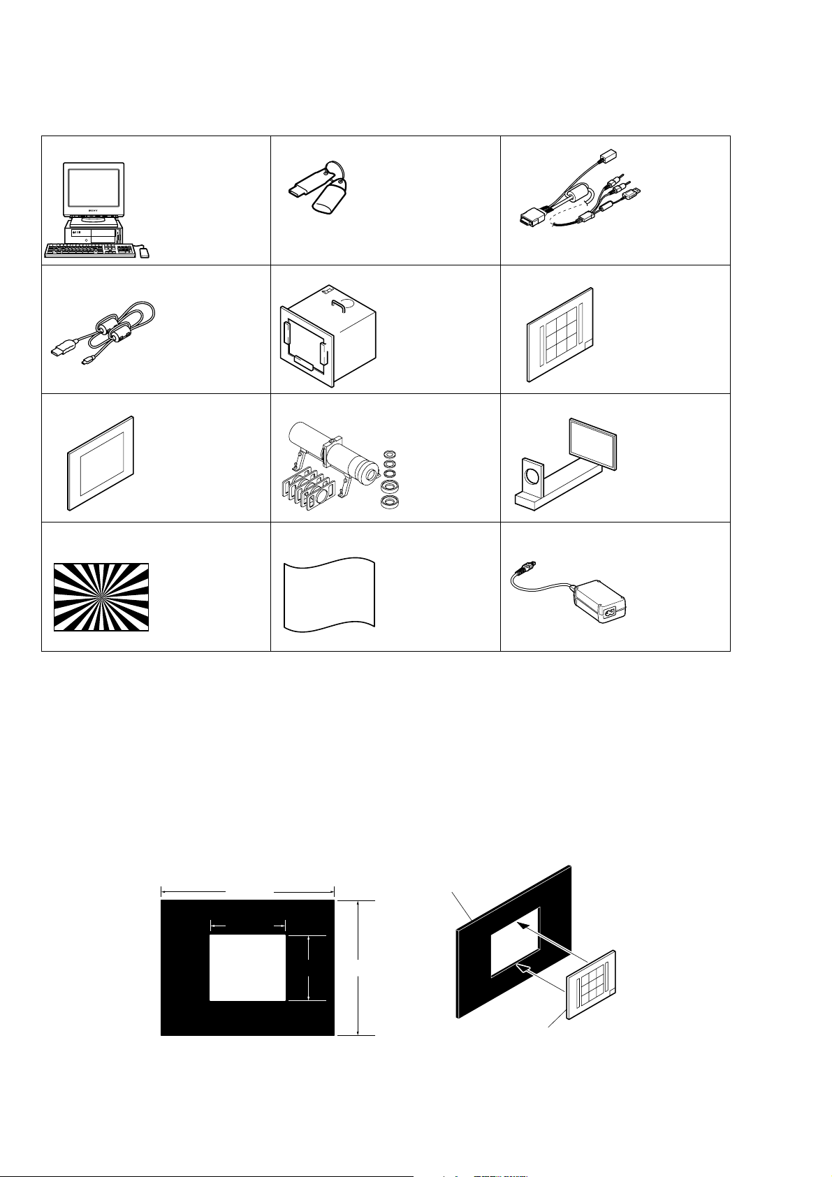
1-2. List of service tools
• Oscilloscope • Color monitor
J-1
J-4
J-7
J-10
Personal computer
(Note 1)
USB cable
1-829-868-41
Clear chart
For PTB-450:
J-6080-621-A
For PTB-1450:
J-6082-560-A
J-2
HASP key and application
for adjustment (SeusEX)
Contact our service headquater of each area
how to get the application for adjustment
(SeusEX) and HASP key.
J-5
Pattern box PTB-450
J-6082-200-A
or
Small pattern box
PTB-1450
J-6082-557-A
J-8
Minipattern box
J-6082-353-B
J-11
J-3
USB, A/V, DC IN cable
for multi-use terminal
1-830-848-21
J-6
9 colors chart (Note 2)
For PTB-1450:
J-6082-562-A
J-9
Flange back
adjustment jig
J-6082-563-A
J-12
Siemens star chart
J-6080-875-A
Back ground paper
J-2501-130-A
AC power adaptor
AC-LS5
1-479-284-51
Fig. 6-1-1
Note 1: Personal computer
OS: Windows98/98SE/Me/2000/XP Home/XP Pro
RAM: 256 MB or more recommended
USB: 2.0 recommended (also compatible with 1.1)
Two connectors are required.
Note 2: In using the 9 colors chart on the pattern box PTB-450, adjust the chart size through the procedure shown below so that it matches
to the pattern box PTB-450.
1) Prepare a woody board A of the thickness 5 mm, and paint it mat-black.
2) Fit the 9 colors chart in the woody board A, and secure the chart with a black tape, etc. to shield the light.
woody boad A
360 mm
155 mm
135 mm
280 mm
woody boad A
DSC-T20/T25_ADJ
9 colors chart
6-4
Page 7

J-14
J-15J-13
Tripod Adaptor
J-6082-577-A
Camera table
J-6082-384-A
Fig. 6-1-2
Note 3: The HD Station must be modified. (Refer to “4. HD Station Modifying Procedure”)
HD Station (CSS-HD1)
(Note 3)
A-1242-190-A
DSC-T20/T25_ADJ
6-5
Page 8

6-1. CAMERA SECTION ADJUSTMENTS
1-1. PREPARATIONS BEFORE ADJUSTMENTS
1-1-1. Preparations
1) Connect the equipment for adjustments according to Fig. 6-1-4.
2) Start up the application for adjustment (SeusEX).
• Connecting the Equipment
PC
(The SeusEX must be installed in the PC.)
OS: Windows 98/98SE/Me/2000/XP
RAM: 256MB or more recommended
USB: 2.0 recommended (also compatible with 1.1)
Two connectors are required.
To Multi connector
HASP Key
Pattern box
L = About 11 cm
Front of the lens
L
Camera
Fig. 6-1-3
DISP SEL switch setting
TV: Video/Camera
System Adjustment
CAMERA: LCD
System Adjustment
AC power adaptor
AC-LS5
(1-479-284-51)
AC IN
To DC IN jack
Video system Adjustment
(Composite video level adj.)
Osilloscope
Terminated
75 Ω
To USB
connector
Color monitor
Video
(yellow)
Audio
(Black)
USB, A/V, DC IN cable
for multi-use terminal
(1-830-848-21)
Fig. 6-1-4
Note: The set must be connected to the modified HD station when performing the “Component out (Y, Pb, Pr) level adjustment” in the
“Video System Adjustment”.
DSC-T20/T25_ADJ
6-6
Page 9
PC
OS: Windows 98/98SE/Me/2000/XP
RAM: 256MB or more recommended
USB: 2.0 recommended
(also compatible with 1.1)
Two connectors are required.
AC IN
AC power adaptor
USB cable
(1-829-868-41)
USB connector
HASP Key
To DC IN jack
To USB
connector
To USB
connector
Terminated
75 Ω
Pr (Red)
Pb (Blue)
Y (Green)
(COMPONENT OUT)
Measurement Point (Component out (Y, Pb, Pr) level adj.)
To COMPONENT OUT
• Connection diagram when “Component out (Y, Pb, Pr) level adjustment” in “Video System Adjustment” is performed.
P
r
P
b
Y
Note: For the USB connection, refer to “4. HD Station Modifying Procedure”.
Fig. 6-1-5
DSC-T20/T25_ADJ
6-7
Page 10
1-1-2. Precautions
1. Setting the Switch
Unless otherwise specified, set the switches as follows and perform adjustments.
1. HOME button (Shooting) ............................................ A uto Adjustment
2. ZOOM button............................................................... WIDE end
3. Digital Zoom
(Settings - Shooting Settings - Shooting Settings 1) .. Off
9 colors chart (Standard picture frame)
A
Green
C14 Blue
Effective picture frame
Fig. a LCD screen or under scan
( )
BA
Yellow
WhiteCyan
monitor TV picture
W14
Red
Magenta
A
2
2. Subjects
1) 9 colors chart (Standard picture frame).
When performing adjustments using the 9 colors chart, adjust
the picture frame as shown in Fig. 6-1-6. (Standard picture
frame)
2) Clear chart (Standard picture frame)
Remove the 9 colors chart from the pattern box and insert a
clear chart in its place. (Do not perform zoom operations during this time)
C
B
C
A = B
C =
C14: Filter for AWB 5800K adjustment
Transparent window
Fig. 6-1-6
B
3
Adjust the camera position and direction
to obtain the LCD screen or the monitor
TV display shown in Fig. a.
DSC-T20/T25_ADJ
6-8
Page 11
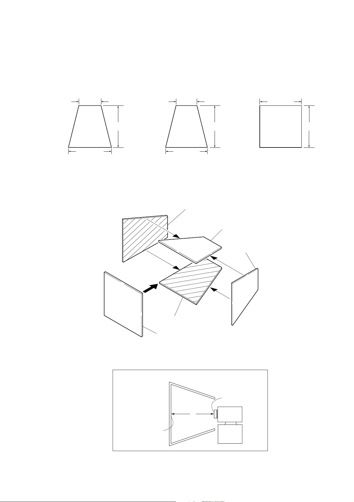
3. Preparing the Flash Adjustment Box
A dark room is required to provide an accurate flash adjustment.
If it is not available, prepare the flash adjustment box as given
below;
1) Provide woody board A, B and C of 15 mm thickness.
woody board A (2)
400 mm
513 mm 513 mm 700 mm
woody board B (2)
Fig. 6-1-7
2) Apply black mat paint to one side of woody board A and B.
3) Attach background paper (J-2501-130-A) to woody board C.
4) Assemble so that the black sides and the background paper
side of woody board A, B and C are internal. (Fig. 6-1-8)
370 mm
700 mm730 mm
woody board A
woody board C (1)
700 mm
woody board B
woody board A
DSC-T20/T25_ADJ
woody board C
Flash adjustment box
Background paper
woody board B
Fig. 6-1-8
L = 50cm
L
Fig. 6-1-9
6-9
Front of the lens
Camera
Page 12
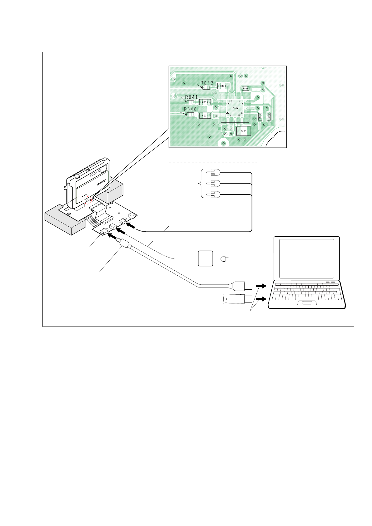
4. HD Station Modifying Procedure
The HD station must be modified to perform the “Component out (Y, Pb, Pr) level adjustment” in the “Video System Adjustment”.
Modify the HD station by the following steps.
1) Prepare the HD station and USB connector.
Part No.
HD station (Note) A-1242-190-A
USB connector 1-794-962-11
Note: You may purchase the commercially available CSS-HD1.
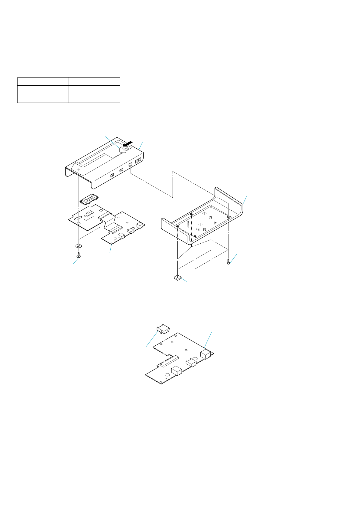
2) Disassemble the HD station in the numerical order given in the following figure to remove the Connector board.
1 Pull the switch
5 Two screws
Upper cabinet
4 Lower cabinet
3 Five screws
6 Connector board/
Multi board
2 Two foot rubbers
Fig. 6-1-10
3) Mount the USB connector on the Connector board.
Mount the USB connector.
Connector board
Fig. 6-1-11
DSC-T20/T25_ADJ
6-10
Page 13

4) Connect four lead wires between USB connector and Multi board.
Wiring diagram when USB connector is added for modification
CN105 CN006
(USB connector) (No mount)
VCC 1Pin 2Pin
D– 2Pin 4Pin
D+ 3Pin 5Pin
GND 5Pin 6Pin
CONNECTOR BOARD (SIDE B)
CN105
24
135
MULTI BOARD (SIDE B)
Fig. 6-1-12
5
4216
CN006
21
22
DSC-T20/T25_ADJ
6-11
Page 14
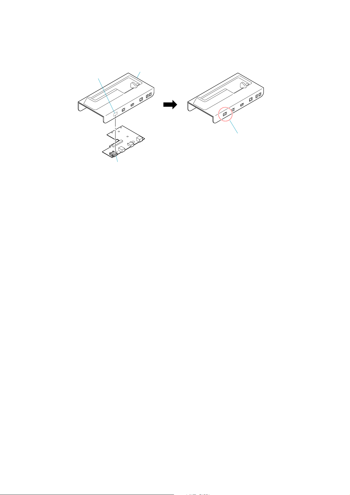
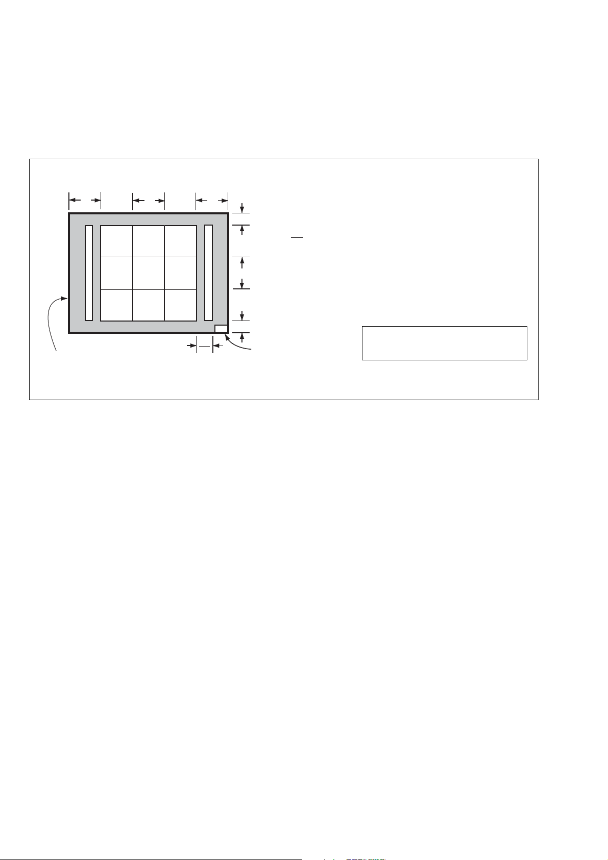
5) Puncture the Upper cabinet to make a window for the USB connector as shown below.
USB connector position
6) Assemble the HD station.
Upper cabinet
Puncture the Upper cabinet.
USB connector
Fig. 6-1-13
DSC-T20/T25_ADJ
6-12
Page 15

1-2. ADJUSTMENT PROGRAM
3
5
4
7
6
2
1
9
0
8
qa
The DSC-T20/T25 is adjusted by the Automatic Adjustment Program. The Automatic Adjustment Program enters automatically
via the SeusEX the adjustment operations that were formerly entered manually by the adjustment remote commander (some items
may be adjusted by manual operation on the operation screen of
the SeusEX).
1. Precautions When Using Automatic Adjustment
Program
1) The Automatic Adjustment Program writes the adjustment re-
sults such as EVR data to the set through two-way communication with the camera via the SeusEX. Accordingly, the Automatic Adjustment Program must be used in the en vironment
where the SeusEX operates.
2) The Automatic Adjustment Program cannot be used when the
SEUS or the SeusCam is running. Exit the SEUS or the
SeusCam before using the Automatic Adjustment Program.
3) The SeusEX must be already started on the PC when using the
Automatic Adjustment Program. W ith the SeusEX not started,
some adjustment items will take time in adjustment.
4) The program run time may vary depending on the environ-
ment of the personal computer used.
2. Start of Automatic Adjustment Program
Double-click the application file (DSC-T20_T25 Auto-Adj
V er_1.0r01.ex e), and the Automatic Adjustment Program will start.
3. Function of Each Button on Main Menu Screen
When the Automatic Adjustment Program started, the Main Menu
screen in Fig. 6-1-14 will appear. On this screen, select each adjustment section.
Fig. 6-1-14
1 [Connecting the Equipment] button
A connection diagram of the equipment is displayed.
2 [CONNECT] button
The mode of Camera is switched to the Adjustment Mode.
When the Adjustment Mode has switched normally, the operation of the buttons 4 - 0 is enabled.
3 [END] button
The mode of Camera is switched to the normal mode.
When the normal mode has switched correctly, the Automatic
Adjustment Program is finished.
4 [DESTINATION DATA WRITE] button
The “DESTINATION DATA WRITE” screen appears.
5 [USB SERIAL N0. INPUT] button
The “USB SERIAL No. INPUT” screen appears.
6 [VIDEO SYSTEM ADJUSTMENT] button
The “VIDEO SYSTEM ADJUSTMENT” screen appears.
7 [CAMERA SYSTEM ADJUSTMENT] button
The “CAMERA SYSTEM ADJUSTMENT” screen appears.
8 [LCD SYSTEM ADJUSTMENT] button
The “LCD SYSTEM ADJUSTMENT” screen appears.
9 [SERVICE MODE] button
The “SERVICE MODE” screen appears.
q; [DATA BACKUP] button
The “DATA BACKUP” screen appears.
qa This part indicates the version of Automatic Adjustment Pro-
gram.
DSC-T20/T25_ADJ
6-13
Page 16

4. Setting of Adjustment Mode
Before performing the adjustment, “Setting of Adjustment Mode”
is required.
5. Release of Adjustment Mode
To finish the adjustment, be sure to perform “Release of Adjustment Mode”.
[Setting method]
1) Connect the Camera to the PC with a USB cable, and turn on
the power switch.
2) Start the Automatic Adjustment Program, and click the [Con-
nect] button on the Main Menu screen.
3) When the following message is displayed, turn off and on again
the power switch of the Camera.
Note: Turning off and on the power switch causes the Cam-
era to be switched to the Adjustment Mode. After the
Camera restarted, click the [OK] button in the message
window.
4) Upon successful completion of the settings in the Adjustment
Mode, the operation of each button on the Main Menu screen
is enabled.
[Releasing method]
1) Click the [END] button on the Main Menu screen.
2) When the following message is displayed, releasing of adjustment mode has completed. Click the [OK] button in the mes-
sage window to exit the Automatic Adjustment Program.
Note: The Camera switches to the normal mode by turning
off and on the power switch. After the adjustment finished, turn off and on again the power switch of the
Camera to confirm that the USB mode screen is displayed.
DSC-T20/T25_ADJ
6-14
Page 17

1-3. DESTINATION DATA WRITE
2. Destination Data Write
Note: The DESTINA TION D A TA WRITE cannot be set with other
than the Service board.
1. Function of Each Button on Destination Data Write
Screen
Click the [DESTINATION DATA WRITE] button on the Main Menu
screen, and the “DESTNATION DATA WRITE” screen in Fig. 61-15 will appear.
1
4
2
3
Fig. 6-1-15
1 [To Menu] button
The Main Menu screen comes back.
2 Model Name List
Selects the model name.
[Writing method]
1) Select the model name with the Model Name List.
2) Select the written destination with the Destination List.
3 Destination List
Selects the written destination.
4 [Data Write] button
Write the destination data to the camera.
3) Click the [Data Write] button.
4) The writing finishes when the following message is displayed.
DSC-T20/T25_ADJ
6-15
Page 18

3. Selectable Language Table
SELECTABLE LANGUAGE
AREA
DSTINATION
J1 J z
JE3 JE zaaa a aaaaa
U2 US za aa a a
CA2 CND
CEE2 aaaaaa az aaaaaaaaa
CEE8 z aaaaa aa aaaaaaaaa
CEE9 z aaaaa aa aaaaaaaaa
CEH UK z aaaaa aa aaaaaaaaa
E15 zaaa a aaaaa
E32 zaaa a aaaaa
DSC-T20DSC-T25
E33 azaa a aaaaa
AU2 AUS za aa a a
HK1 HK
CN2 CH
KR2 KR aaaa azaaaa
AR2 AR azaa a aaaaa
BR1 BR
CEE2 aaaaaa az aaaaaaaaa
CEE8 z aaaaa aa aaaaaaaaa
CEE9 z aaaaa aa aaaaaaaaa
E32 E zaaa a aaaaa
AU2 AUS za aa a a
HK1 HK
AEP
AEP
Japanese
E
z: INITIAL LANGUAGE
French
English
za aa a a
zaaa a aaaaa
aaaz a aaaaa
aaza a aaaaa
zaaa a aaaaa
German
Italian
Spanish
Chinese
Simplified
Portuguese
Dutch
Chinese
Traditional
Korean
Russian
Arabic
Persian
Thai
Melayu
Swedish
Danish
Norwegian
Polish
Finnish
Czech
Hungarian
Table 6-1-2
Greek
Turkish
Default
VIDEO OUT
NTSC
PAL
NTSC
NTSC
PAL
PAL
PAL
PAL
PAL
PAL
NTSC
PAL
PAL
PAL
NTSC
NTSC
NTSC
PAL
PAL
PAL
PAL
PAL
PAL
DSC-T20/T25_ADJ
6-16
Page 19

1-4. USB SERIAL No. INPUT
The set is shipped with a unique ID (USB Serial No.) written in it.
This ID has not been written in a new board for service, and therefore it must be entered after the board replacement.
If original ID can be read from the board before replacement, read
it from the board before replacement using the “SERIAL READ/
WRITE” screen, and then write it after replacement.
If original ID cannot be read from the board before replacement,
write the ID for service using the “MANUAL WRITE” screen.
(The ID for service is different from the ID written when the set is
shipped.) Enter the PRODUCT ID (last 5 characters of model name)
and SERIAL No. into the screen and write them.
1. Function of Each Button on USB Serial No. Input
Screen
Click the [USB SERIAL No. INPUT] button on the Main Menu
screen, and “USB SERIAL No. INPUT” screen in Fig. 6-1-16
will appear.
1
2
6
3
4
5
7
Fig. 6-1-16
1 [To Menu] button
The Main menu screen comes back.
2 Display area
The “PRODUCT ID”, “SERIAL No.” and “ASCII TRANSLATION” are displayed.
For the “ASCII TRANSLATION”, the last 5 characters of
model name are displayed if the PRODUCT ID is set from the
model name in the MANUAL WRITE. F or the PR ODUCT ID
set in the factory, the model name is not displayed b ut “?” etc.
will be displayed.
3 [Check Serial] button
The USB SERIAL No. data is read from the camera and displayed in the display area.
4 [Read and Save] button
The USB SERIAL No. data is read from the camera and saved
in PC as a file.
5 [Load and Write] button
The USB SERIAL No. data is loaded from the file saved in
PC and written to the camera.
6 Input area
Enter “PRODUCT ID” and “SERIAL No.” when writing the
ID for service.
The “PRODUCT ID” is set from the last 5 characters of model
name if the model name is selected.
For the “SERIAL No.”, read it from the label on the camera
body and enter it.
DSC-T20/T25_ADJ
7 [Write Manually] button
The USB SERIAL No. data entered in the input area is written
to the camera.
6-17
Page 20

1-5. VIDEO SYSTEM ADJUSTMENTS
1-5-1. Function of Each Button on Video System
Adjustment Screen
Click the [VIDEO SYSTEM ADJUSTMENT] button on the Main
Menu screen, and the “VIDEO SYSTEM ADJUSTMENT”
screen in Fig. 6-1-17 will appear.
1
2
5
3
4
Fig. 6-1-17
1 [To Menu] button
The Main Menu screen comes back.
2 [Preparation] button
Notes for adjustment or jigs used are displayed.
3 [Start] button
Each adjustment “Composite Video Level Adjustment” or
“Component out (Y, Pb, Pr) Level Adjustment” starts.
4 [Reboot] button
When this button is clicked, the camera is rebooted.
5 [Release Data Setting] button
The data setting at the adjustment is cancelled.
During the data setting, the button color changes from “white”
to “red”. When the data setting is cancelled, the button color
returns to “white”.
(Use this button when an error occurred in the video adjustment. If the adjustment completed successfully, the data setting is automatically cancelled and the button color returns to
“white”.)
1-5-2. Adjustment Items of VIDEO System Adjust-
ment
The adjustment items of video system adjustment are as listed in
T able 6-1-3. The Automatic Adjustment Program ex ecutes the adjustment items if the VIDEO Adjustment Start button is clicked.
Button
Name
VIDEO
Adjustment
Adjustment Measurement Point
Composite Video
Level Adj.
COMPONENT OUT
Y Level Adj.
COMPONENT OUT
Pb Level Adj.
COMPONENT OUT
Pr Level Adj.
VIDEO terminal of USB, A/V, DC IN
cable for multi-USB terminal
(75 ohm terminated)
R040 on Multi board (HD Station) Oscilloscope
R041 on Multi board (HD Station) Oscilloscope
R042 on Multi board (HD Station) Oscilloscope
Table 6-1-3
DSC-T20/T25_ADJ
6-18
Measuring
Instrument
Oscilloscope
Adjusting Address
Block Page Address
11
11
11
11
60
60
60
60
06DE
06BF
06C0
06C1
Page 21

1-5-3. Adjusting Method
1. Composite Video Level Adjustment
[Automatic Adjustment Program execution items and
sequence]
1. Data Setting during Video Adj.
2. Composite Video Level Adj.
3. VIDEO OUT Level Check
4. Release of Data Setting during Video Adj.
[Adjusting method]
1) Click the [Start] button of the Composite Video Level Adj.
2) The Automatic Adjustment Program executes the “1. Data
Setting during Video Adj.”.
3) If “1. Data Setting during V ideo Adj.” completed successfully,
the following screen is displayed during the execution of “2.
Composite Video Level Adj.”. Using the [Up]/[Down] button
on the screen, adjust so that the sync level of the video signals
satisfies the specified value. After the adjustment, click the
[End] button in the screen.
4) If the [End] button is clicked, “3. VIDEO OUT Level Check”
will be executed. The following message and screen are displayed. Check that the sync signal level and burst level of the
video signals satisfies the specified value, and click the [OK]
button in the message.
5) If the [End] button is click ed, “2. Composite Video Level Adj. ”
and “4. Release of Data Setting during Video Adj.” will be
executed.
6) Upon successful completion of all item the Composite Video
Level Adjustment, the following message is displayed. Click
the [OK] button.
DSC-T20/T25_ADJ
6-19
Page 22

2. Component Video Level Adjustment
[Automatic Adjustment Program execution items and
sequence]
1. Data Setting during Video Adj.
2. COMPONENT OUT Y Level Adj.
3. COMPONENT OUT Pb Level Adj.
4. COMPONENT OUT Pr Level Adj.
5. Release of Da ta Setting during Video Adj.
[Adjusting method]
1) Click the [Start] button of the Component Video Level Adjust-
ment.
2) The Automatic Adjustment Program executes the “1. Data
Setting during Video Adj.”.
3) If “1. Data Setting during V ideo Adj.” completed successfully,
the following screen is displayed during the execution of “2.
COMPONENT OUT Y Level Adj.”. Using the [Up]/[Down]
button on the screen, adjust so that the Y signal level satisfies
the specified value. After the adjustment, check that the sync
level of the Y signals satisfies the specified value, and click
the [End] button in the screen.
5) After that, the following screen is displayed during the execution of “4. COMPONENT OUT Pr Level Adj. ”. Using the [Up]/
[Down] button on the screen, adjust so that the Pr signal level
satisfies the specified value. After the adjustment, check that
the sync level of the Pr signals satisfies the specified value,
and click the [End] button in the screen.
6) If the [End] button is clicked, the items from “2. COMPO-
NENT OUT Y Lev el Adj. ” to “4. COMPONENT OUT Pr Le vel
Adj.” and “5. Release of Data Setting during Video Adj.” will
be executed.
7) Upon successful completion of all item the Component Video
Level Adjustment, the following message is displayed. Click
the [OK] button.
4) After that, the following screen is displayed during the execution of “3. COMPONENT OUT Pb Level Adj. ”. Using the [Up]/
[Down] button on the screen, adjust so that the Pb signal level
satisfies the specified value. After the adjustment, check that
the sync level of the Pb signals satisfies the specified value,
and click the [End] button in the screen.
DSC-T20/T25_ADJ
6-20
Page 23

1-6. CAMERA SYSTEM ADJUSTMENTS
1-6-1. Function of Each Button on Camera System
Adjustment Screen
Click the [CAMERA SYSTEM ADJUSTMENT] button on the Main
Menu screen, and the “CAMERA SYSTEM ADJUSTMENT”
screen in Fig. 6-1-18 will appear.
1
2
3
2
5
3
Fig. 6-1-18
1 [To Menu] button
The Main Menu screen comes back.
2 [Preparation] button
Notes for adjustment or jigs used are displayed.
3 [Start] button
Each adjustment from “Camera Adjustment 1” to “Camera
Adjustment 7” starts.
4 [Reboot] button
When this button is clicked, the camera is rebooted.
5 [Release Data Setting] button
The data setting at the adjustment is cancelled.
During the data setting, the button color changes from “white”
to “red”. When the data setting is cancelled, the button color
returns to “white”.
(Use this button when an error occurred in the camera adjustment 1-6. If the adjustment completed successfully, the data
setting is automatically cancelled and the button color returns
to “white”.)
4
DSC-T20/T25_ADJ
6-21
Page 24

1-6-2. Adjustment Items of Camera System Adjust-
j
ment
The adjustment items of camera system adjustment are as listed in
Table 6-1-4. The Automatic Adjustment Program divides the adjustment items into seven, camera adjustment 1-6. Clicking either
CAMERA Adjustment Start button allows the adjustment item
which corresponds to that button to be executed.
The adjustment conditions of the subject and filter vary depending on which item is adjusted. The Adjustment Program displays
an instruction for the subject and filter as a message during the
adjustment.
Ad
Button Name Adjustment Subject
CAMERA Adjustment 1 Hall Adj. Not required 11 61 0E00 to 0E04
(Note 1) Wide Limit Adj. Not required 11 61 0F18, 0F19
Siemens star chart with ND filter
CAMERA Adjustment 2 Flange Back Adj.
CAMERA Adjustment 3 Flange Back Check
F No. Compensation 11 61 095A, 095B
Measure Gain, LV Adj. 11 61 0961 to 0968
Mechanical Shutter Adj. 11 61
AWB 3200K-5800K
Standard Data Input
CAMERA Adjustment 4
CAMERA Adjustment 5 Strobe Adj. Flash adjustment box (50 cm) 11 61
CAMERA Adjustment 6 Auto Focus Illumination Check Flash adjustment box (50 cm) 11 61 0F10 to 0F15
CAMERA Adjustment 7
Note 1: The Automatic Adjustment Program does not support the “Wide Limit Adjustment”.
Note 2: Dark Siemens star chart.
AWB 3200K-5800K Check - - Color Reproduction
Adj. & Check
CCD Linearity Check - - CCD White Defect
Compensation Check
CCD Black Defect
Compensation Check
Angular Velocity Sensor
Sensitivity Adj.
for minipattern box (Note 2) or
Flange back adjustment jig
Siemens star
(1.0m from front the lens)
(Luminance: 200 to 400 lux)
Clear chart
(Standard picture frame)
9 color chart
(Standard picture frame)
Clear chart
(Standard picture frame)
Not required 11 61 0E10, 0E11
Block Page Address
11 61
11 61
11 61 0C50 to 0C57
11 61 0200 to 02FF
11 61 0000 to 00FF
usting Address
0663,
069C to 069F,
0F1C, 0F1D,
0F20, 0F21,
0F24,
0F27 to 0F39,
0F3E, 0F3F,
0F52, 0F53
-- -
0980 to 0985,
0998 to 099A
0C00 to 0C21,
0C24 to 0C49
09C2 to 09C5,
0C72 to 0C75
DSC-T20/T25_ADJ
Table 6-1-4
6-22
Page 25

1-6-3. Adjusting Method
1. CAMERA Adjustment 1
Note: There is no magnetic substance within around 8 cm of the
camera.
[Automatic Adjustment Program execution items and
sequence]
1. Data Setting during Camera Adj.
2. Hall Adj.
3. Release of Data Setting during Camera Adj.
[Adjusting method]
1) Click the [Start] button of CAMERA Adjustment 1.
2) The Automatic Adjustment Program ex ecutes the “1. Data Setting during Camera Adj.”.
3) Upon successful completion of “1. Data Setting during Camera Adj.”, the following screen is displayed.
Processing after Completing Adjustment:
[Checking method]
1) [HOME screen] t [Settings] t [Shooting Settings] t
[Shooting Settings 2] t Select [Auto Orientation] to “ON”.
2) Shoot with the set in respective positions (a) to (c) shown below.
3) Check the pictures in the Playback mode to confirm that the
pictures are rotated correctly.
(a)
4) If the [OK] button is clicked, “2. Hall Adj.” and “3. Release of
Data Setting during Camera Adj.” will be executed.
5) Upon successful completion of all items of the CAMERA Adjustment 1, the following message is displayed. Click the [OK]
button.
(b)
(c)
Fig. 6-1-19
DSC-T20/T25_ADJ
6-23
Page 26

2. Wide Limit Adjustment
Adjustment to remove variations at the wide end of the inner focus lens.
Adjustment Block 11
Adjustment Page 61
Adjustment Address 0F18, 0F19
2-1. Adjusting method when the lens is replaced:
Adjusting method:
Order Block
1 11 61 0F18 Set the data. (Note)
2 11 61 0F19 Set the data. (Note)
3 Save the data.
4
Note: The data of block: 11, page: 61, address: 0F18 and 0F19,
that are set in the Orders 1 and 2 as described above, are
shown on the data sheet supplied with the replacement lens
for repair.
Set the upper single byte of the 2-byte data shown on the
sheet to address: 0F19, and the lower byte of the data to the
address: 0F18.
Page Address
Procedure
Perform “Flange Back
Adjustment”.
2-2. Adjusting method when replacement of lens is
not required and the SY-170 board is replaced:
When the data of block: 11, page: 61, address: 0F18 and
0F19 can be read from the defective SY-170 board before replacement, and both of the data are not “00”:
Adjusting method:
Order Block
1 11 61 0F18 Set the previous data
2 11 61 0F19 Set the previous data
3 Save the data.
4
When the data of block: 11, page: 61, address: 0F18 and
0F19 can be read out from the defective SY-170 board
before replacing it, and both of the data are “00”:
1) Replace the lens with the replacement lens and perform “2-1.
Adjusting method when the lens is replaced”.
When the data of block: 11, page: 61, address: 0F18 and
0F19 cannot be read from the defective SY-170 board:
1) Replace the lens with the replacement lens and perform “2-1.
Adjusting method when the lens is replaced”.
Page
Address Procedur
Perform “Flange Back
Adjustment”.
Wide Limit Data (2-byte data)
XXXX
DSC-T20/T25_ADJ
Data for Block: 11,
Page: 61, Address: 0F18
Data for Block: 11,
Page: 61, Address: 0F19
Fig. 6-1-20
6-24
Page 27

3. CAMERA Adjustment 2
Flange back adjustment jig
Below 3 cm
Camera
[Automatic Adjustment Program execution items and
sequence]
1. Data Setting during Camera Adj.
2. Flange Back Adj.
3. Release of Data Setting during Camera Adj.
Preparation of Flange Back Adj.
(Using the minipattern box)
1) The minipattern box is installed as shown in the following figure.
Note 1: The attachment lenses are not used.
2) Install the minipattern box so that the distance between it and
the front of lens of camera is less than 3 cm.
3) Make the height of minipattern box and the camera equal.
4) Check the output voltage of the regulated power supply is the
specified voltage ± 0.01 Vdc.
5) Check that the center of Siemens star chart meets the center of
shot image screen with the zoom lens at TELE end and WIDE
end respectively.
Specified voltage: The specified voltage varies according to the
minipattern box, so adjustment the power supply output voltage to the specified voltage written on the sheet which is supplied with the minipattern box.
Below 3 cm
Preparation of Flange Back Adj.
(Using the flange back adjustment jig)
(Luminance: about 300 lux)
Note 2: When using the flange back adjustment jig, take care of
the following points:
• For the illumination, use a light source such as an incandescent lamp or inverter type fluorescent light free
from flickering.
• Do not make an adjustment in the environment where
fluorescent lamp flickering occurs even if the illuminance can be ensured with the room illumination only.
Use an incandescent lamp or inverter type fluorescent
light at a place free from the influence of room illumination.
1) Install the flange back adjustment jig so that the distance between it and the front of lens of camera is less than 3 cm.
2) Make the height of flange back adjustment jig and the camera
equal.
3) Check that the center of chart meets the center of shot image
screen with the zoom lens at TELE end and WIDE end respectively.
Minipattern box
Output voltage : Specified voltage ± 0.01 Vdc
Red (+)
Black (–)
Yellow (SENS +)
White (SENS –)
Black (GND)
Camera
Fig. 6-1-22
Regulated power supply
Output current : more than 3.5 A
Need not connected
Fig. 6-1-21
DSC-T20/T25_ADJ
6-25
Page 28

[Adjusting method]
1) If the [Start] button of the CAMERA Adjustment 2 is click ed,
the following message is displayed.
If “Wide Limit Adjustment” is necessary, click the [Cancel]
button to interrupt the Adjustment Program, and perform “1.
Wide Limit Adjustment”.
2) If the [OK] button is clicked, the Automatic Adjustment Pro-
gram executes “1. Data Setting during Camera Adj.”.
3) Upon successful completion of the “1. Data Setting during
Camera Adj. ”, the follo wing message is displayed. Set the subject by referring to “Preparation of Flange Back Adj.”.
4. CAMERA Adjustment 3
[Automatic Adjustment Program execution items and
sequence]
1. Data Setting during Camera Adj.
2. Flange Back Check
3. Release of Data Setting during Camera Adj.
[Adjusting method]
1) Click the [Start] button of the CAMERA Adjustment 3.
2) The Automatic Adjustment Program e xecutes “1. Data Setting
during Camera Adj.”.
3) Upon successful completion of the “1. Data Setting during
Camera Adj.”, the following message is displayed. Set the subject in accordance with the message.
4) Click the [OK] button is clicked, “2. Flange Back Check” is
executed. The following messages are displayed, and then operate the camera to make a check in accordance with the messages.
4) If the [OK] button is clicked, “2. Flange Back Adj.” and “3.
Release of Data Setting during Camera Adj. ” will be e xecuted.
5) Upon successful completion of all items of the CAMERA
Adjustment 2, the following message is displayed. Click the
[OK] button.
5) Upon completion of “2. Flange Back Check”, “3. Release of
Data Setting during Camera Adj.” is executed.
6) Upon successful completion of all items of the CAMERA
Adjustment 3, the following message is displayed. Click the
[OK] button.
DSC-T20/T25_ADJ
6-26
Page 29

5. Picture Frame Setting (Standard Picture Frame)
In the “CAMERA Adjustment 4”, set the picture frame so as to
attain the positions shown in the following figure when shooting
the 9 colors chart.
Check on the oscilloscope
Measurement Point: Video terminal of USB, A/V, DC IN cable for
multi-use terminal (75 Ω terminated)
1. Horizontal period
A = B
A
B
A
6. CAMERA Adjustment 4
[Automatic Adjustment Program execution items and
sequence]
1. Data Setting during Camera Adj.
2. Picture Frame Setting
3. F No. Compensation
4. Measure Gain, LV Adj.
5. Mechanical Shutter Adj.
6. AWB 3200K-5800K Standard Data Input
7. AWB 3200K-5800K Check
8. Color Reproduction Adj. & Check
9. CCD Linearity Check
10. CCD White Defect Compensation Check
11. CCD Black Defect Compensation Check
12. Release of Data Setting during Camera Adj.
[Adjusting method]
1) Click the [Start] button of the CAMERA Adjustment 4.
2) The Automatic Adjustment Program ex ecutes the “1. Data Setting during Camera Adj.”.
3) Upon successful completion of “1. Data Setting during Camera Adj.”, “2. Picture Frame Setting” is executed. The following message is displayed, and then referring to Fig. 6-1-23 to
Fig. 6-1-25, set the subject and click the [OK] button.
Fig. 6-1-23
2. Vertical period
B
V
C =
CC
B
3
Fig. 6-1-24
Check on the monitor TV or the LCD screen
B
C =A = B
3
C14: Filter for AWB 5800K adjustment
AAB
YellowGreen
WhiteCyan
W14
Red
After that, the next message is displayed. Then, change the chart
in accordance with the message.
C
B
Effective picture frame
DSC-T20/T25_ADJ
BlueC14
Magenta
Transparent window
Fig. 6-1-25
C
A
2
6-27
Page 30

4) Click the [OK] button, and the items from “3. F No. Compen-
sation” to “5. Mechanical Shutter Adj.” will be executed.
5) Upon successful completion of “5. Mechanical Shutter Adj.”,
the following message is displayed. Change the chart in accordance with the message.
6) Click the [OK] button, and the “6. AWB 3200K-5800K Stan-
dard Data Input” and “7. AWB 3200K-5800K Check” will be
executed.
7) After that, “8. Color Reproduction Adj. & Check” will be executed. Upon completion of adjustment, the check result is
displayed on the Color Reproduction Check screen.
At this time, the following message is displayed, and click the
[Yes] button if the check result display at the upper right of
Color Reproduction Check screen is OK, or the [No] button if
NG.
8) Upon successful completion of “8. Color Reproduction Adj.
& Check”, the following message is displayed. Change the
chart in accordance with the message.
9) Click the [OK] button, and the items from “9. CCD Linearity
Check” to “12. Release of Data Setting during Camera Adj.”
will be executed.
10) Upon successful completion of all items of the CAMERA
Adjustment 4, the following message is displayed. Click the
[OK] button.
DSC-T20/T25_ADJ
6-28
Page 31

7. CAMERA Adjustment 5
Note: “CAMERA Adjustment 5” is available only once after the
power is turned on. If the adjustment is retried, turn off the
power and turn on again.
[Automatic Adjustment Program execution items and
sequence]
1. Data Setting during Camera Adj.
2. Strobe Adj.
3. Release of Data Setting during Camera Adj.
[Adjusting method]
1) Click the [Start] button of CAMERA Adjustment 5.
2) The Automatic Adjustment Program executes the “1. Data
Setting during Camera Adj.”.
3) Upon successful completion of the “1. Data Setting during
Camera Adj.”, the following message is displayed. Set the subject in accordance with the message.
(For the Flash adjustment box, refer to “3. Preparing the Flash
Adjustment Box” (see page 6-9).)
4) Press the [OK] button, and the “2. Strobe Adj.” will be ex-
ecuted.
5) During execution of “2. Strobe Adj.”, the following message
is displayed. After checking the flashing of strobe light, click
the [OK] button. (This message is displayed 2 times during
execution of adjustment.)
8. CAMERA Adjustment 6
[Automatic Adjustment Program execution items and
sequence]
1. Data Setting during Camera Adj.
2. Auto Focus Illumination Check
3. Release of Data Setting during Camera Adj.
[Adjusting method]
1) Click the [Start] button of CAMERA Adjustment 6.
2) The Automatic Adjustment Program executes the “1. Data
Setting during Camera Adj.”.
3) Upon successful completion of the “1. Data Setting during
Camera Adj. ”, the follo wing message is displayed. Set the subject in accordance with the message.
(For the Flash adjustment box, refer to “3. Preparing the Flash
Adjustment Box” (see page 6-9).)
4) Press the [OK] button, and the “2. Auto Focus Illumination
Check” will be executed.
5) Upon successful completion of the “2. Auto Focus Illumination Check”, the “3. Release of Data Setting during Camera
Adj.” will be executed successively.
6) Upon successful completion of all items of the CAMERA
Adjustment 6, the following message is displayed. Click the
[OK] button.
6) Upon successful completion of “2. Strobe Adj.”, “3.Release
of Data Setting during Camera Adj.” is executed.
7) Upon successful completion of all items of the CAMERA
Adjustment 5, the following message is displayed. Click the
[OK] button.
DSC-T20/T25_ADJ
6-29
Page 32

9. CAMERA Adjustment 7
Perform this adjustment only when replacing the angular velocity
sensor or lens block. When the microprocessor, circuit etc. is damaged, don't perform this adjustment but check the operations only.
9-1. Precaution before adjustment
Before adjustment, read the following data and record them.
When the SY-170 board is replaced, read out the data before the
replacement, and record them.
Reading out method:
1) Read out the data in Block:11, Page:61, Address:0E10, and
name this as Dp.
2) Read out the data in Block:11, Page:61, Address:0E11, and
name this as Dy.
9-2. Preparation when the angular velocity
sensor or the SY-170 board is replaced
Note down the sensitivity displayed on the angular velocity sensor of
the repair parts. At this time, note down also to which board it was
attached to.
Be sure to check because if attached incorrectly, the screen will vibrate up and down or left and right during the steady shot operations.
Precautions on the Parts Replacement
The PITCH sensor and the YAW sensor are different parts.
Preparation:
1) Read the PITCH sensor (SY -170 board SE502) sensiti vity written on repair parts, and named this as S
.
502
2) Read the YAW sensor (SY-170 board SE501) sensitivity written on repair parts, and named this as S
.
501
SY-170 BOARD (SIDE B)
SE501
12
43
YY
12
PP
SE502
43
Precautions on Angular Velocity Sensor
The sensor incorporates a precision oscillator. Handle it with care as
if it dropped, the balance of oscillator will be disrupted and operations will not be performed properly.
Adjustment Block 11
Adjustment Page 61
Adjustment Address 0E10, 0E11
Note: The sensor sensitivity of SE501 and SE502 of the SY-170
board is written only repair parts.
PP: PITCH sensor sensitivity t S
YY: YAW sensor sensitivity t S
502
501
Fig. 6-1-26
How to read the sensitivity data of angular velocity sensor
With the pins 1 and 2 of angular velocity sensor placed in the
lower position, read the data value.
Description example :
For the sensor sensitivity value 60
43
60
12
Hand Writing
Fig. 6-1-27
DSC-T20/T25_ADJ
6-30
Page 33

9-3. Preparation when the lens is replaced
Note down the PITCH/YAW data on the replacement lens for repair.
Adjustment Block 11
Adjustment Page 61
Adjustment Address 0E10, 0E11
Note: The PITCH/YAW data of lens is written only repair parts.
Preparation:
1) Read the PITCH data written on repair parts, and named this
.
as L
1
2) Read the YAW data written on repair parts, and named this as
L2.
9-4. Angular Velocity Sensor Sensitivity Adjustment
[Adjusting method]
1) Click the [Start] button of Camera Adjustment 7, and the fol-
lowing screen will appear.
PITCH/YAW Data
X.XX / X.XX
Fig. 6-1-28
YAW data t L
PITCH data t L
2) Input the previous data (Dp, Dy) into screen.
If the previous data cannot be read, give a check to the checkbox
at lower left of screen.
, S
3) Input the sensitivity of respective sensors (S
) read at
501
502
“Preparation” into the screen.
If only either sensor was replaced, give a check to the checkbox
for the sensor not replaced at the lower left of the screen.
4) Input the PITCH/YAW data of lens (L1, L2) read at “Preparation” into the screen.
If the lens was not replaced, give a check to the checkbox at
2
1
the lower left of the screen.
5) Click the [OK] button, and the adjustment data is then calcu-
lated from the sensor sensitivity value and the calculation result is written to the memory in the camera.
6) Upon successful completion of the data writing, the following
screen will appear. Check that the steady shot function operates normally.
DSC-T20/T25_ADJ
6-31
Page 34

1-7. LCD SYSTEM ADJUSTMENTS
1-7-1. Function of Each Button on LCD System
Adjustment Screen
Click the [LCD SYSTEM ADJUSTMENT] button on the Main Menu
screen, and the “LCD SYSTEM ADJUSTMENT” screen in Fig.
6-1-29 will appear.
1
2
3
Fig. 6-1-29
1 [To Menu] button
The Main Menu screen comes back.
2 [Start] button
“LCD Adjustment” starts.
3 [Reboot] button
When this button is clicked, the camera is rebooted.
1-7-2. Adjustment Items of LCD System Adjustment
The adjustment items of LCD system adjustment are as listed in
Table 6-1-5. The Automatic Adjustment Program executes the adjustment items if the LCD Adjustment Start button is clicked.
Button
Name Signal Page Address
LCD V-COM Adj. 11 60 0301
Adjustment White Balance Adj. 11 60 0309, 030A
Adjustment
Adjusting Address
Table 6-1-5
DSC-T20/T25_ADJ
6-32
Page 35

1-7-3. Adjusting Method
[Automatic Adjustment Program execution items and
sequence]
1. Data Setting during LCD Adj.
2. V -COM Adj.
3. White Balance Adj.
[Adjusting method]
1) Click the [Start] button of the LCD Adjustment.
2) The Automatic Adjustment Program e xecutes “1. Data Setting
during LCD Adj.”.
3) Upon successful completion of the “1. Data Setting during LCD
Adj.”, the following screen is displayed during the execution
of “2. V-COM Adj.”. Using the [Up]/[Down] button on the
screen, adjust so that the brightness of portions A and B on the
LCD panel is equal. After the adjustment, click the [End] button in the screen.
5) Upon successful completion of all item the LCD Adjustment,
the following message is displayed. Click the [OK] button.
4) If the [End] button is click ed, the following screen is displayed
during the execution of “3. White Balance Adj.”. Check that
the LCD screen is not colored. If colored, using the [Up]/[Down]
button on the screen, adjust so that the LCD screen is not colored. After the adjustment, click the [End] button in the screen.
DSC-T20/T25_ADJ
6-33
Page 36

1-8. ERROR
In the case of an error during the execution of adjustment, the
Automatic Adjustment Program interrupts the processing at that
point, and displays an error message, and then terminates the program execution there.
1-8-1. Error Message
When an error message is displayed, perform the remedy given
below , and then retry adjustment. If the error message is displayed
though the remedy was performed, the circuits will be faulty.
1. Connect Error, Adjust Control Error
Symptom USB communication with the set is abnormal.
Cause • USB cable is not inserted tightly.
• Power supply is not installed correctly.
• Communication with SeusEX is abnormal.
Remedy • Disconnect the USB cable once, and then re-
connect it tightly and check that the set is in
“USB Mode”.
• Install the power supply correctly.
• Start the SeusEX and click the [Connect] to
check that the connection state is established.
2. RESET the CAMERA and Try Again
3. Adjustment Time Out
This part indicates
the adjustment
item in which
an error occurred.
Symptom Adjustment does not finish within the specified
time.
Cause • Adjustment conditions are wrong.
• Data error exists in the camera.
Remedy • Check that the conditions such as a subject
are correct.
• Reset the camera.
4. Adjustment NG
This part indicates
the adjustment
item in which
an error occurred.
Symptom The adjusted data does not become the speci-
fied value.
Cause • Adjustment conditions are wrong.
• Data error exists in the camera.
Remedy • Check that the conditions such as a subject
are correct.
• Reset the camera.
Symptom The camera is not ready for adjustment.
Cause Data error exists in the camera.
Remedy Reset the camera.
DSC-T20/T25_ADJ
6-34
Page 37

5. Data Save Error
How to cancel the data setting during
adjustment is display here.
1-8-2. Precautions When an Error Occurred
The Automatic Adjustment Program sets the data for adjustment
before the adjustment starts. Accordingly, if the adjustment terminates by an error, the data during the adjustment may be left in the
camera.
Note 1: With this data left in the camera, the camera will not op-
erate normally.
In this case, the [Release Data Setting] button is displayed in “red”
on the screen as shown figures below. Click the
[Release Data Setting] button to cancel the data setting. When the
data setting is cancelled, the button color becomes “white”.
Note 2: When “Data Save Error” occurred, the [Release Data
Setting] button is displayed in “white”.
To cancel the data setting, perform it on the SeusEX Operation screen. How to cancel the data setting is displayed
in the error message.
Symptom data cannot be saved normally. (The data set-
ting during adjustment cannot be cancelled)
Cause • Data writing to the flash memory failed.
• Connection is faulty.
• Power supply is not installed correctly.
Remedy • On the SeusEX Operation screen, [Set] the
data to the pages and addresses displayed in
the message, and [Save] them. (Cancel manually the data setting during adjustment.)
• Check the connection.
• Install the power supply correctly.
Video System Adjustment screen
Camera System Adjustment screen
DSC-T20/T25_ADJ
6-35
Page 38

6-2. SERVICE MODE
2-1. APPLICATION FOR ADJUSTMENT (SeusEX)
The adjustment software (SeusEX) can change operational coefficients of signal processing, EVR data, etc. same as the adjustment remote commander. The SeusEX performs two-way communication between PC and camera using the USB terminal. The
two-way communication result data can be written in the nonvolatile memory.
1. Connection
1) Connect the HASP key to the USB terminal of the PC.
2) Connect the PC and camera with the USB cable.
3) Start the SeusEX on the PC.
4) Click [Connect] on the SeusEX screen. If the connection is
normal, the SeusEX screen will be as shown in Fig. 6-2-1,
indicating the “connected” state.
Note: The SeusEX will go in “disconnect” state, if the cam-
era is turned off (for instance, by resetting the set). In
such a case, click [Connect] on the SeusEX screen to
restore the “connected” state.
2. Operation
• Block change
To change the block, click [Block] on the SeusEX screen and
enter the block to be changed. The block is displayed in hexadecimal notation.
•Page change
To change the page, click [Page] on the SeusEX screen and enter
the page to be changed. The page is displayed in hexadecimal
notation.
• Address change
To change the address, click [Address] on the SeusEX screen
and enter the address to be changed. The address is displayed in
hexadecimal notation.
• Data change
To change the data, click [Set] on the SeusEX screen and enter
the data. The data is displayed in hexadecimal notation.
This operation does not write the data to the nonvolatile memory.
• Data writing
To write the data to the EEPROM, click [Write] on the SeusEX
screen and enter the data value to be written.
To write the data to the flash memory, change the data value
using the [Set] on the SeusEX screen and then click [Save] to
save the data.
Fig. 6-2-1
• Data reading
The data displayed on the SeusEX screen are the data values at
the time when the pages and addresses were set, and they are not
updated automatically. To check the data change, click [Read]
on the SeusEX screen and update the displayed data.
DSC-T20/T25_ADJ
6-36
Page 39

2-2. SERVICE MODE
1. Function of Each Button on Service Mode Screen
Click the [SERVICE MODE] button on the Main Menu screen, and
the “SERVICE MODE” screen in Fig. 6-2-2 will appear.
1
2. Switch Check
Click the [Switch Check] button on the SERVICE MODE screen,
and the “SWITCH CHECK” screen will appear.
2
3
Fig. 6-2-2
1 [To Menu] button
The Main Menu screen comes back.
2 [Switch Check] button
“SWITCH CHECK” screen appears.
3 [LED Check] button
“LED CHECK” screen appears.
4 [Record Data] button
“RECORD DATA” screen appears.
5 [Aging] button
“AGING” screen appears.
4
5
Using method:
Click the [Start] button, and the switch check will start.
During execution of switch check, the pressed switch is displayed
in orange. Also, once the switch was pressed, its name characters
change to blue in color.
DSC-T20/T25_ADJ
6-37
Page 40

3. LED Check
Click the [LED Check] button on the SERVICE MODE screen,
and the “LED CHECK” screen will appear.
Using method:
LED ON or OFF can be controlled with [LED ON] or [LED OFF]
button on the screen.
4. Record Data
Click the [Record Data] button on the SERVICE MODE screen,
and the “RECORD DATA” screen will appear.
The record data such as Lifetime counter is displayed.
Initializing method:
Click the [Clear Shot Count] button on the screen, and the Lifetime Count data will be initialized.
DSC-T20/T25_ADJ
6-38
Page 41

5. Aging
On the AGING screen, various types of aging can be executed.
Select the type of aging to be executed with the Aging Mode
Select buttons.
Aging Mode Select button
Supply the power not from an AC adapter but from the fully char ged
battery and execute the aging until the battery end, so that its battery use time and how many pictures the camera can record/play
back can be checked.
During the execution of aging, the camera automatically repeats
recording/playback.
During the recording, if the recording memory capacity becomes
full, its memory is automatically formatted.
Accordingly, when executing the aging, insert the Memory Stick
into the camera and set the Memory Stick as default media.
(1) 10MODE
In the 10MODE, perform continuous recording in accordance with
the CIPA Standard. When the 10MODE starts, the following operation is repeated until the battery end.
1) The zoom moves to the TELE end.
2) The camera records a still picture with a strobe light flashed at
the maximum level.
3) The camera stands by for the time (sec.) set to the “Rec Interval”.
4) The zoom moves to the WIDE end.
5) The camera records a still picture without flashing a strobe
light.
6) The camera stands by for the time (sec.) set to the “Rec Interval”.
7) Each time 10 still pictures are recorded, the power is turned
off, and after the time (min.) set to the “Power Off Interval”,
the power is turned on again.
At the start of 10MODE, the counter in the camera is initialized.
This counter counts the number of recording times during the
execution of 10MODE, and it holds the counts even during the
power off.
[Preparation]
For the aging, set the camera as follows:
Switch setting:
1) Flash button...................................................................... Auto
Home Items
1) Shooting ....................................................... Auto Adjustment
2) AF Mode
(Settings - Shooting Settings - Shooting Settings 1) ....Single
DSC-T20/T25_ADJ
6-39
Page 42

10MODE screen and functions of each item
(2) AGING_REC
In the A GING_REC mode, still pictures are continuously recorded
at the interval (sec.) set to the “Rec Interval”.
At the start of AGING_REC, the counter in the camera is initialized. This counter counts the number of recording times during
the execution of AGING_REC, and it holds the counts even during the power off.
1
23
7
1 [Preparation] button
Notes for aging is displayed.
2 Rec Interval setting and display
The setting of recording interval (sec.) is displayed. The setting can be changed by entering a numeric value in this field.
3 Power Off Interval setting and display
The setting of power off interval (min.) is displayed. The setting can be changed by entering a numeric value in this
field.
4 [START] button
The settings of parameters specified by the Rec Interval and
Power Off Interval for execution of 10MODE are sent to the
camera.
The 10MODE starts when the camera power is turned off once
and then on again.
The settings for execution of 10MODE are held until the camera detects the battery end. They cannot be reset by the power
off or RESET button. T o interrupt the 10MODE, use the [STOP]
button.
4
5
6
AGING_REC screen and functions of each item
1
2
6
1 [Preparation] button
Notes for aging is displayed.
2 Rec Interval setting and display
The setting of recording interval (sec.) is displayed. The setting can be changed by entering a numeric value in this
field.
3 [START] button
The AGING_REC starts. In the AGING_REC mode, the aging starts immediately when the [START] button is clicked.
At the battery end, the AGING_REC stops. To interrupt the
AGING_REC, use the [STOP] button, though the AGING_REC
stops also by the power off or RESET button.
3
4
5
5 [STOP] button
The settings for execution of 10MODE are reset.
6 [GET] button
After the 10MODE was executed, the number of recording
times is got from the counter in the camera. The result is displayed in the “Count” display field.
7 Count display
The number of recording times got by the [GET] button is displayed.
4 [STOP] button
The AGING_REC stops.
5 [GET] button
After the AGING_REC was executed, the number of recording times is got from the counter in the camera. The result is
displayed in the “Count” display field.
6 Count display
The number of recording times got by the [GET] button is displayed.
DSC-T20/T25_ADJ
6-40
Page 43

(3) AGING_MREC
5
3
4
1
6
2
In the AGING_MREC mode, motion pictures are continuously
recorded for the time (sec.) set to the “Rec Time” at the interval
(sec.) set to the “Rec Interval”.
At the start of AGING_MREC, the counter in the camera is initialized. This counter counts the number of recording times during the execution of AGING_MREC, and it holds the counts even
during the power off.
AGING_MREC screen and functions of each item
(4) AGING_PB
In the A GING_PB mode, pictures are continuously played back at
the interval (sec.) set to the “Play Back Interval”.
At the start of AGING_PB, the counter in the camera is initialized. This counter counts the number of play back times during
the execution of AGING_PB, and it holds the counts even during
the power off.
AGING_PB screen and functions of each item
1
23
7
1 [Preparation] button
Notes for aging is displayed.
2 Rec Time setting and display
The setting of recording time (sec.) is displayed. The setting
can be changed by entering a numeric value in this field.
3 Rec Interval setting and display
The setting of recording interval (sec.) is displayed. The setting can be changed by entering a numeric value in this field.
4 [START] button
The AGING_MREC starts. In the AGING_MREC mode, the
aging starts immediately when the [START] button is clicked.
At the battery end, the A GING_MREC stops. To interrupt the
AGING_MREC, use the [STOP] button, though the
AGING_MREC stops also by the power of f or RESET button.
5 [STOP] button
The AGING_MREC stops.
6 [GET] button
After the A GING_MREC was ex ecuted, the number of recording times is got from the counter in the camera. The result is
displayed in the “Count” display field.
4
5
6
1 [Preparation] button
Notes for aging is displayed.
2 Play Back Interval setting and display
The setting of play back interval (sec.) is displayed. The setting can be changed by entering a numeric value in this field.
3 [START] button
The AGING_PB starts. In the AGING_PB mode, the aging
starts immediately when the [START] button is clicked.
At the battery end, the AGING_PB stops. To interrupt the
AGING_PB, use the [STOP] button, though the AGING_PB
stops also by the power off or RESET button.
4 [STOP] button
The AGING_PB stops.
5 [GET] button
After the AGING_PB was executed, the number of play back
times is got from the counter in the camera. The result is displayed in the “Count” display field.
6 Count display
The number of play back times got by the [GET] button is
displayed.
DSC-T20/T25_ADJ
7 Count display
The number of recording times got by the [GET] button is displayed.
6-41
Page 44

2-3. DATA BACKUP
With the “DATA BACKUP”, the adjustment data in the camera
can be backed up in the PC as a file.
The adjustment data that can be backed up are as follows.
System Control Section:
1) Video System Adjustments
2) LCD System Adjustments
Camera Control Section:
1) Camera System Adjustments
1. Function of Each Button on Data Backup Screen
Click the [DATA BACKUP] button on the Main Menu screen, and
the “DATA BACKUP” screen in Fig. 6-2-3 will appear.
1
2
3
Fig. 6-2-3
1 [To Menu] button
The Main Menu screen comes back.
2 [Data Read and Save] button
Read the adjustment data from the camera and save them in
PC as a file.
3 [Data Load and Write] button
Load the adjustment data from the file saved in PC and write
them to the camera.
DSC-T20/T25_ADJ
6-42E
Page 45

Reverse
985219551.pdf
Revision History
Ver.
1.0
Date
2007.03
History
Official Release
Contents
—
S.M. Rev.
issued
—
DSC-T20/T25_ADJ
 Loading...