

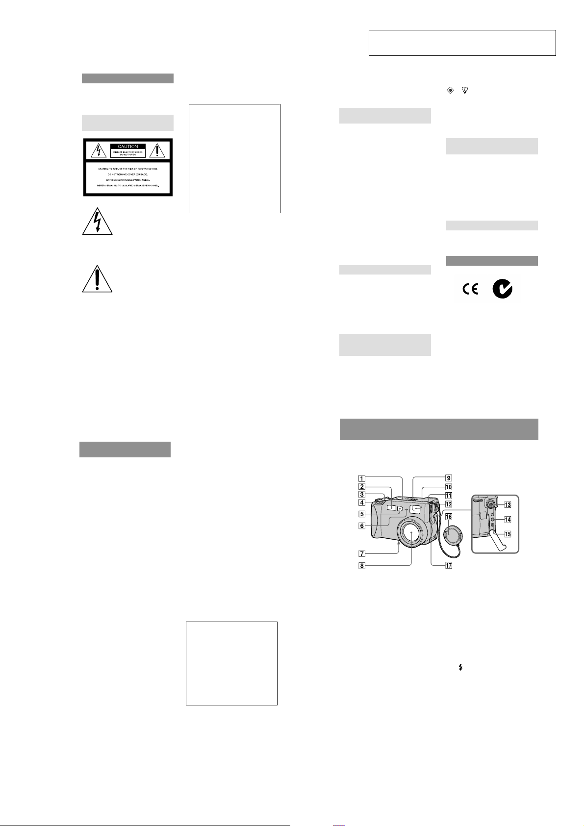
Sony DSC-S70 Service manual

DSC-S70
SERVICE MANUAL
Level 2
This service manual contains information for Japanese model as well.
On the SY-58 board
This service manual procides the information that is premised the
circuit board replacement service and not intended repair inside the
SY-58 board.
Therefore, schematic diagram, printed wiring board and electrical
parts list of the SY-58 board are not shown.
The following pages are not shown.
Ver 1.0 2000. 03
US Model
Canadian Model
AEP Model
UK Model
E model
Hong Kong Model
Australian Model
Chinese Model
Korea Model
Tourist Model
Japanese Model
SY-58 board
Schematic diagram ................................... Pages 4-15 to 4-30
Printed wiring board ................................. Pages 4-11 to 4-14
Electrical parts list .................................... Pages 6-11 to 6-15
The above-described information is shown in service manual
Level 3.
System
Image device
1/1.8 type color CCD
Lens
3× zoom lens
f = 7 – 21 mm
(34 – 102 mm when converted
into a 35 mm still camera)
F = 2.0 – 2.5
Exposure control
Automatic exposure
White balance
Automatic, Indoor, Outdoor,
Hold
Data system
Movie: MPEG1
Still: JPEG, GIF (in TEXT
mode), TIFF
Audio with still image:
MPEG1 (Monaural)
Recording medium
“Memory Stick”
Flash
Recommended recording
distance:
11 7/8 inches to 8 1/4 feet
(0.3 m to 2.5 m)
SPECIFICATIONS
Output connector
A/V OUT (Monaural)
Minijack
Video: 1 Vp-p, 75 Ω,
unbalanced, sync negative
Audio: 327 mV (at a 47 kΩ
load)
Output impedance: 2.2 kΩ
Digital I/O (USB)
Special minijack
External flash jack
Minijack
LCD screen
Used LCD panel
2 type TFT (Thin Film
Transistor active matrix) drive
Total number of dots
123 200 (560×220) dots
General
Used battery pack
NP-FM50
Power requirements
7.2 V
Power consumption
(during recording)
3.9 W
Operation temperature
32˚F to 104˚F
(0˚C to 40˚C)
Storage temperature
–4˚F to +140˚F
(–20˚C to +60˚C)
Maximum dimensions
4 5/8×2 7/8×2 5/8 inches
(117×71×64 mm) (w/h/d)
Mass
Approx. 15 oz (423 g)
(including battery pack NPFM50, “Memory Stick,”
shoulder strap and lens cap
etc.)
Built-in microphone
Electret condenser microphone
Built-in speaker
Dynamic speaker
AC-L10 AC power
adaptor
Power requirements
100 to 240 V AC, 50/60 Hz
Rated output voltage
DC 8.4 V, 1.5 A in operating
mode
Operation temperature
32˚F to 104˚F (0˚C to 40˚C)
Storage temperature
–4˚F to +140˚F
(–20˚C to +60˚C)
DIGITAL STILL CAMERA
Maximum dimensions
5×1 9/16×2 1/2 inches
(125×39×62 mm) (w/h/d)
Mass
Approx. 10 oz (280 g)
NP-FM50 battery pack
Used battery
Lithium ion battery
Maximum voltage
DC 8.4 V
Nominal voltage
DC 7.2 V
Capacity
8.5 Wh (1 180 mAh)
Design and specifications are
subject to change without
notice.

Supplied accessories
134
5678
90qaqs
2
1 AC-L10 AC power adaptor
2 Power cord (1)
3 A/V connecting cable (1)
4 NP-FM50 Battery pack (1)
5 Shoulder strap (1)
6 Lens cap strap (1)
7 Memory Stick (8MB) (1)
8 Lens cap (1)
9 Bundle soft (2000) (1)
(Compact Disk)
0 USB cable (1)
qa 2-pin conversion adaptor (1)
E model
qs 2-pin conversion adaptor (1)
Tourist model
SAFETY-RELATED COMPONENT WARNING!!
COMPONENTS IDENTIFIED BY MARK 0 OR DOTTED
LINE WITH MARK 0 ON THE SCHEMATIC DIAGRAMS
AND IN THE PARTS LIST ARE CRITICAL TO SAFE
OPERATION. REPLACE THESE COMPONENTS WITH
SONY PARTS WHOSE PART NUMBERS APPEAR AS
SHOWN IN THIS MANUAL OR IN SUPPLEMENTS PUBLISHED BY SONY.
SAFETY CHECK-OUT
After correcting the original service problem, perform the following
safety checks before releasing the set to the customer.
1. Check the area of your repair for unsoldered or poorly-soldered connections. Check the entire board surface for solder
splashes and bridges.
2. Check the interboard wiring to ensure that no wires are
“pinched” or contact high-wattage resistors.
3. Look for unauthorized replacement parts, particularly transistors, that were installed during a previous repair. Point them
out to the customer and recommend their replacement.
ATTENTION AU COMPOSANT AYANT RAPPORT
À LA SÉCURITÉ!
LES COMPOSANTS IDENTIFIÉS P AR UNE MARQUE 0
SUR LES DIAGRAMMES SCHÉMATIQUES ET LA LISTE
DES PIÈCES SONT CRITIQUES POUR LA SÉCURITÉ
DE FONCTIONNEMENT. NE REMPLACER CES COMPOSANTS QUE PAR DES PIÈCES SONY DONT LES
NUMÉROS SONT DONNÉS DANS CE MANUEL OU
DANS LES SUPPLÉMENTS PUBLIÉS PAR SONY.
4. Look for parts which, though functioning, show obvious signs
of deterioration. Point them out to the customer and recommend their replacement.
5. Check the B+ voltage to see it is at the values specified.
6. Flexible Circuit Board Repairing
• Keep the temperature of the soldering iron around 270 ˚C
during repairing.
• Do not touch the soldering iron on the same conductor of
the circuit board (within 3 times).
• Be careful not to apply force on the conductor when sol-
dering or unsoldering.
– 2 –

TABLE OF CONTENTS
Section Title Page Section Title Page
SERVICE NOTE................................................................... 5
1. GENERAL
Identifying the Parts................................................................. 1-1
Preparing the Power Supply.................................................... 1-2
Setting the Date and Time....................................................... 1-3
Inserting the “Memory Stick” ................................................... 1-4
Recording Still Images ............................................................ 1-4
Recording Moving Images....................................................... 1-5
Playing Back Still Images ........................................................ 1-5
Playing Back Moving Images .................................................. 1-6
Viewing Images Using a Personal Computer ......................... 1-6
Image File Storage Destinations and Image Files.................. 1-7
Before Performing Advanced Operations ............................... 1-7
Various Recording ................................................................... 1-9
Various Playback ..................................................................... 1-11
Editing .................................................................................. 1-12
Precautions.............................................................................. 1-13
On “Memory Sticks” ................................................................. 1-14
Using Your Camera Abroad ..................................................... 1-14
Troubleshooting ....................................................................... 1-14
Warning and Notice Messages ............................................... 1-15
Self-diagnosis Display ............................................................. 1-15
Display Window Indicators ...................................................... 1-16
LCD Screen Indicators ............................................................ 1-16
2. DISASSEMBLY
• Attachment of CPC-9 Jig ...................................................... 2-1
2-1. Front Cabinet Block Assembly ...................................... 2-2
2-2. LCD Holder and Flash Unit ........................................... 2-2
2-3. Battery Lid Assembly and Speaker............................... 2-3
2-4. Control Switch Block and Front Panel .......................... 2-3
2-5. MS-54 Board and BT Holder Assembly ........................ 2-4
2-6. Lens Block Assembly .................................................... 2-4
2-7. SY-58 Board and DD-141 Board................................... 2-5
• Service Position .................................................................... 2-5
2-8. Control Switch Block, PD-128 Board and
Indicator Module............................................................ 2-6
2-9. SL-56 Board .................................................................. 2-7
2-10. Circuit Boards Location ................................................. 2-8
2-11. Flexible Boards Location ............................................... 2-8
3. BLOCK DIAGRAMS
3-1. Overall Block Diagram................................................... 3-1
3-8. Power Block Diagram 1 ................................................. 3-15
3-9. Power Block Diagram 2 ................................................. 3-17
4. PRINTED WIRING BOARDS AND
SCHEMATIC DIAGRAMS
4-1. Frame Schematic Diagram (1/2) ................................... 4-3
Frame Schematic Diagram (2/2)................................... 4-5
4-2. Pr inted Wiring Boards and Schematic Diagrams ......... 4-7
• CD-282
Printed Wiring Board ................................................ 4-7
• CD-282 (CCD Imager)
Schematic Diagram .................................................. 4-8
• MS-54
Printed Wiring Board ................................................ 4-9
• MS-54 (FU, Memory Stick)
Schematic Diagram .................................................. 4-9
• PD-128
Printed Wiring Board ................................................ 4-31
• PD-128 (LCD Drive)
Schematic Diagram .................................................. 4-33
• PD-128 (Timing Generator)
Schematic Diagram .................................................. 4-35
• SL-56
Printed Wiring Board ................................................ 4-37
• SL-56 (Switch, LCD, Jack)
Schematic Diagram .................................................. 4-39
• DD-141
Printed Wiring Board ................................................ 4-41
• DD-141 (DC/DC Converter)
Schematic Diagram .................................................. 4-43
• DD-141 (Video)
Schematic Diagram .................................................. 4-45
• DD-141 (USB)
Schematic Diagram .................................................. 4-47
4-3. Waveforms..................................................................... 4-49
4-4. Parts Location ............................................................... 4-52
5. ADJUSTMENTS
Before Starting Adjustment ..................................................... 5-1
1-1. Adjusting Items when Replacing
Main Parts and Boards.................................................. 5-2
5-1. Camera Section Adjustment ......................................... 5-3
1-1. Preparations Before Adjustment................................... 5-3
1-1-1. List of Service Tools ................................................. 5-3
1-1-2. Preparations ............................................................. 5-4
1-1-3. Discharging of the Flashlight Power Supply ............ 5-4
1-1-4. Precautions .............................................................. 5-6
1. Setting the Switch .................................................... 5-6
2. Order of Adjustments ............................................... 5-6
3. Subjects.................................................................... 5-6
4. Preparing the Flash Adjustment Box ....................... 5-7
1-2. Initialization of B, D, E, F, 7 Page Data ......................... 5-8
1-2-1. Initialization of D Page Data .................................... 5-8
1. Initializing the D Page Data ...................................... 5-8
2. Modification of D Page Data .................................... 5-8
3. D Page Table ............................................................ 5-8
1-2-2. Initialization of B, E, F, 7 Page Data ........................ 5-9
1. Initializing the B, E, F, 7 Page Data ......................... 5-9
2. Modification of B, E, F, 7 Page Data ........................ 5-9
3. B Page Table ............................................................ 5-9
4. E Page Table ............................................................ 5-9
5. F Page Table............................................................. 5-10
6. 7 Page Ta ble ............................................................. 5-11
1-3. Video System Adjustments ........................................... 5-12
1. Video Sync Level Adjustment ....................................... 5-12
2. Video Burst Level Adjustment....................................... 5-12
1-4. Camera System Adjustment ......................................... 5-13
1. Flange Back Adjustment
(Using the Minipattern Box) .......................................... 5-14
2. Flange Back Check ....................................................... 5-15
3. F No. Standard Data Input ............................................ 5-16
4. Mechanical Shutter Adjustment .................................... 5-16
5. Picture Frame Setting.................................................... 5-17
6. Light Level Adjustment.................................................. 5-18
7. Mixed Color Cancel Adjustment .................................... 5-18
8. Auto White Balance Standard Data Input ..................... 5-19
9. Auto White Balance Adjustment ................................... 5-19
10. Color Reproduction Adjustment.................................... 5-20
11. Color Reproduction Check............................................ 5-21
12. White Balance Check.................................................... 5-22
13. Strobe White Balance Adjustment ................................ 5-23
14. Strobe Light Level and White Balance Check .............. 5-23
15. CCD Black Defect Compensation................................. 5-24
16. CCD White Defect Compensation ................................ 5-24
1-5. LCD System Adjustments ............................................. 5-25
1. LCD Initial Data Input.................................................... 5-26
2. VCO Adjustment (PD-128 Board)................................. 5-26
3. D Range Adjustment (PD-128 Board) .......................... 5-27
4. Bright Adjustment (PD-128 Board) ............................... 5-27
5. Contrast Adjustment (PD-128 Board)........................... 5-28
6. Color Adjustment (PD-128 Board) ................................ 5-28
7. V-COM Level Adjustment (PD-128 Board) ................... 5-29
8. V-COM Adjustment (PD-128 Board)............................. 5-29
9. White Balance Adjustment (PD-128 Board) ................. 5-30
1-6. System Control System Adjustments ........................... 5-31
1. Battery Down Adjustment ............................................. 5-31
– 3 –

Section Title Page
5-2. Service Mode ................................................................ 5-32
2-1. Adjusting Remote Commander ..................................... 5-32
1. Used Adjusting Remote Commander ........................... 5-32
2. Precautions upon Using
the Adjusting Remote Commander............................... 5-32
2-2. Data Process ................................................................. 5-33
2-3. Service Mode ................................................................ 5-34
1. Setting the Test Mode.................................................... 5-34
2. Bit V alue Discrimination ................................................ 5-34
3. Switch Check (1) ........................................................... 5-34
4. Switch Check (2) ........................................................... 5-35
5. LED Check .................................................................... 5-35
6. LCD Check .................................................................... 5-35
6. REPAIR PARTS LIST
6-1. Exploded Views ..............................................................6-1
6-1-1. Front Panel Section .............................................6-1
6-1-2. Front Cabinet Section ..........................................6-2
6-1-3. Rear Cabinet Section...........................................6-3
6-1-4. Lens Block Assembly...........................................6-4
6-2. Electrical Parts List ........................................................6-5
.* The color reproduction frame is shown on page 118.
– 4 –
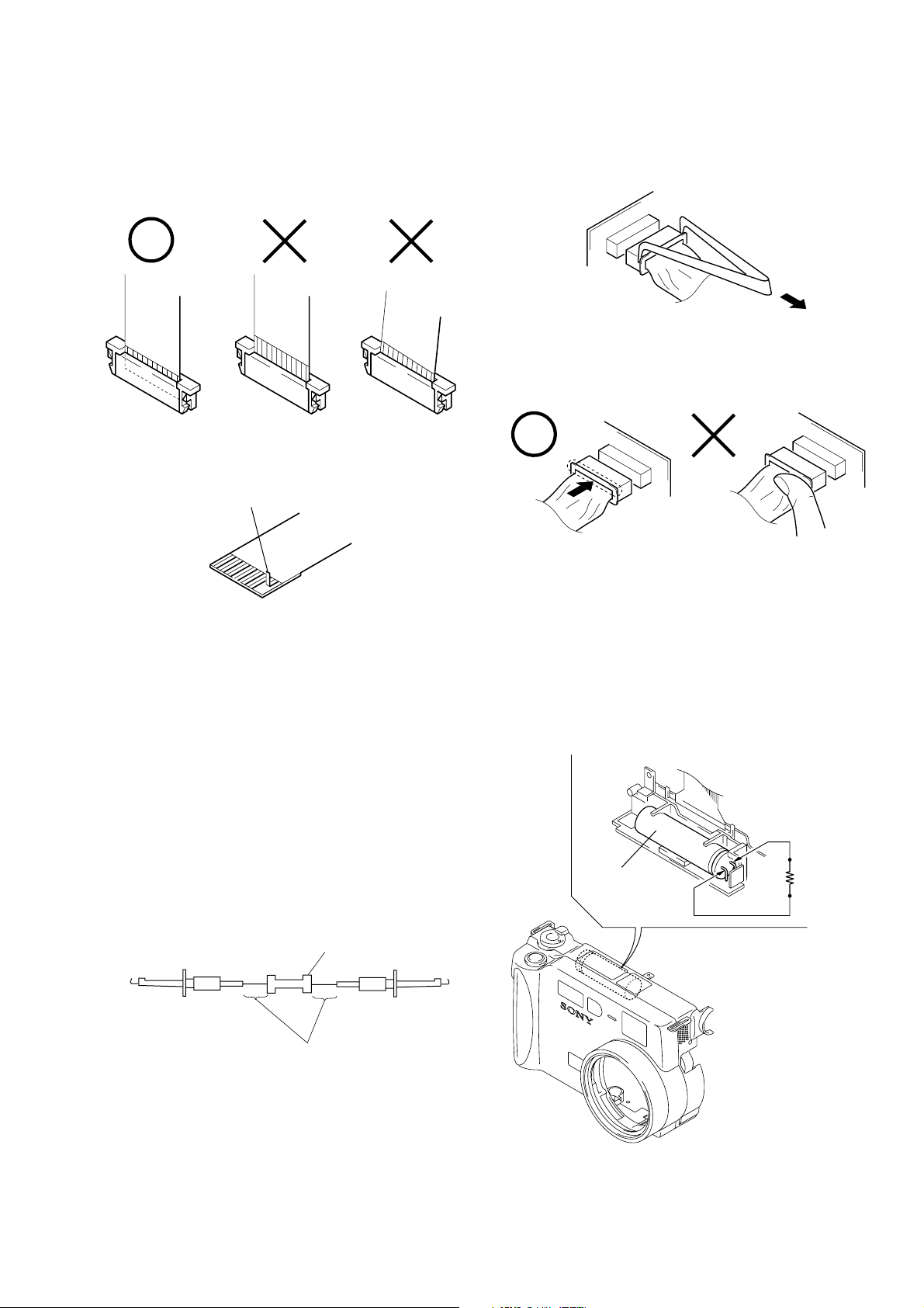
SERVICE NOTE
When installing a connector, don’t press down at wire of connector.
Be in danger of the snapping of a wire.
• NOTE FOR REPAIR
Make sure that the flat cable and flexible board are not cracked of
bent at the terminal.
Do not insert the cable insufficiently nor crookedly.
Cut and remove the part of gilt
which comes off at the point.
(Take care that there are some
pieces of gilt left inside)
When remove a connector, don’t pull at wire of connector.
Be in danger of the snapping of a wire.
[Discharging of the FLASH unit’s charging capacitor]
The charging capacitor of the FLASH unit is charged up to the
maximum 300 V potential.
There is a danger of electric shock by this high voltage when the
battery is handled by hand. The electric shock is caused by the
charged voltage which is kept without discharging when the main
power of the DSC-S70 is simply turned off. Therefore, the remaining voltage must be discharged as described below.
Preparing the Short Jig
T o preparing the short jig, a small clip is attached to each end of a
resistor of 1 kΩ /1 W (1-215-869-11).
Wrap insulating tape fully around the leads of the resistor to prevent electrical shock.
1 kΩ/1 W
Wrap insulating tape.
Discharging the Capacitor
Short-circuit between the positive and the negative terminals of
charged capacitor with the short jig about 10 seconds.
Capacitor
R: 1 KΩ/1 W
(Part code:
1-215-869-11)
– 5 –

[Description on Self-diagnosis Display]
Self-diagnosis display
• C: ss
You can reverse the camera
malfunction yourself. (However,
contact your Sony dealer or local
authorized Sony service facility
when you cannot recover from the
camera malfunction.)
• E: ss
Contact your Sony dealer or local
authorized Sony service facility.
Display Code
C:32:ss
C:13:ss
E:61:ss
E:91:ss
Turn the power off and on again.
Format the “Memory stick”.
Insert a new “Memory Stick”.
Checking of lens drive circuit.
*1
Checking of flash unit or replacement
of flash unit.
Countermeasure
Cause
Trouble with hardware.
Unformatted memory stick is inserted.
Memory stick is broken.
When failed in the focus and zoom
initialization.
Abnormality when flash is being
charged.
Note: The error code is cleared if the battery is removed, except defective flash, unit.
*1: The error display is given in two ways.
*2: When the flash charging failed, Page : D, Address: 67. Data: 04 are written.
After repair, be sure to write Page: D, address: 67. Data: 00.
Caution Display During Error
SYSTEM ERROR
FORMAT ERROR
MEMORY STICK ERROR
—
*2
– 6 –
SECTION 1
6
Getting started
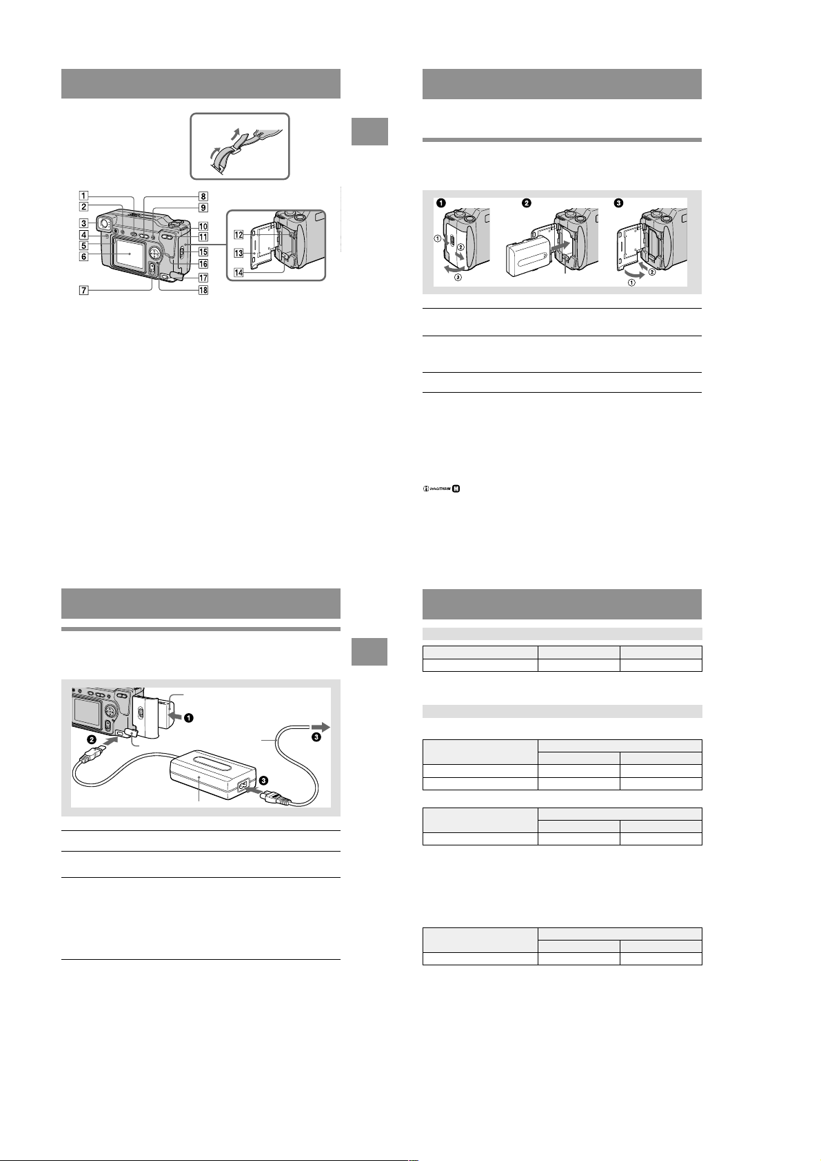
Identifying the parts
See the pages in parentheses for details of operation.
A Display window
B Flash (20)
C MODE selector (30)
D Shutter button (16) (21)
E Photocell window for flash
Do not block while recording.
F Self-timer/recording lamp
G Tripod receptacle (bottom
surface)
Use a tripod with a screw length of
less than 9/32 inch (6.5 mm). You
will be unable to firmly secure the
camera to tripods having longer
screws, and may damage the
camera.
H Lens
When cleaning the lens, first return
the lens to the fully retracted
position and turn off the power,
then gently wipe the lens.
I Built-in microphone
Do not touch while recording.
J Finder window
K Hook for lens cap/strap
L Finder adjustment dial (17)
M (External flash) jack
N USB jack (26) (27)
O A/V OUT jack (48)
Audio output is monaural.
P Lens cap
Be sure to remove the lens cap
before turning on your camera.
Q Speaker
GENERAL
DSC-S70
This section is extracted from DSC-S70
instruction manual.
WARNING
To prevent fire or shock hazard, do
not expose the unit to rain or
moisture.
For the Customers in the
U.S.A.
This symbol is intended to
alert the user to the presence
of uninsulated “dangerous
voltage” within the
product’s enclosure that
may be of sufficient
magnitude to constitute a
risk of electric shock to
persons.
This symbol is intended to
alert the user to the presence
of important operating and
maintenance (servicing)
instructions in the literature
accompanying the
Never expose the battery pack to
temperature above 140˚F (60˚C), such as in
a car parked in the sun or under direct
sunlight.
If you have any questions about this
product, you may call:
or write to:
appliance.
Sony Customer Information Center
1-800-222-SONY (7669)
Sony Customer Information Center
1 Sony Drive, Mail Drop #T1-11, Park
Ridge, NJ 07656
2
CAUTION
You are cautioned that any changes or
modifications not expressly approved in this
manual could void your authority to operate
this equipment.
Declaration of Conformity
Trade Name: SONY
Model No.: DSC-S70
Responsible Party:Sony Electronics Inc.
Address: 1 Sony Drive, Park
Telephone No.: 201-930-6972
This device complies with Part 15 of the
FCC Rules. Operation is subject to the
following two conditions: (1) This
device may not cause harmful
interference, and (2) this device must
accept any interference received,
including interference that may cause
undesired operation.
Note:
This equipment has been tested and found to
comply with the limits for a Class B digital
device, pursuant to Part 15 of the FCC
Rules. These limits are designed to provide
reasonable protection against harmful
interference in a residential installation. This
equipment generates, uses, and can radiate
radio frequency energy and, if not installed
and used in accordance with the
instructions, may cause harmful interference
to radio communications. However, there is
no guarantee that interference will not occur
in a particular installation. If this equipment
does cause harmful interference to radio or
television reception, which can be
determined by turning the equipment off and
on, the user is encouraged to try to correct
the interference by one or more of the
following measures:
— Reorient or relocate the receiving
antenna.
— Increase the separation between the
equipment and receiver.
— Connect the equipment into an outlet
on a circuit different from that to which
the receiver is connected.
— Consult the dealer or an experienced
radio/TV technician for help.
Ridge, NJ 07656
USA
The shielded interface cable recommended
in this manual must be used with this
equipment in order to comply with the limits
for a digital device pursuant to Subpart B of
Part 15 of FCC Rules.
For the Customers in the
U.S.A. and Canada
DISPOSAL OF LITHIUM ION
BATTERY.
LITHIUM ION BATTERY.
DISPOSE OF PROPERLY.
You can return your unwanted lithium ion
batteries to your nearest Sony Service
Center or Factory Service Center.
Note:
In some areas the disposal of lithium ion
batteries in household or business trash may
be prohibited.
For the Sony Service Center nearest you call
1-800-222-SONY (United States only)
For the Sony Factory Service Center nearest
you call 416-499-SONY (Canada only)
Caution:
Do not handle damaged or leaking lithium
ion battery.
For the Customers in Canada
CAUTION
TO PREVENT ELECTRIC SHOCK, DO
NOT USE THIS POLARIZED AC PLUG
WITH AN EXTENSION CORD,
RECEPTACLE OR OTHER OUTLET
UNLESS THE BLADES CAN BE FULLY
INSERTED TO PREVENT BLADE
EXPOSURE.
NOTICE FOR THE
CUSTOMERS IN THE UNITED
KINGDOM
A moulded plug complying with BS 1363 is
fitted to this equipment for your safety and
convenience.
Should the fuse in the plug supplied need to
be replaced, a 5 AMP fuse approved by
ASTA or BSI to BS 1362, (i.e. marked with
or mark) must be used.
If the plug supplied with this equipment has
a detachable fuse cover, be sure to attach the
fuse cover after you change the fuse. Never
use the plug without the fuse cover. If you
should lose the fuse cover, please contact
your nearest Sony service station.
For the Customers in
Germany
Directive:EMC Directive 89/336/EEC.92/
31/EEC
This equipment complies with the EMC
regulations when used under the following
circumstances:
• Residential area
• Business district
• Light-industry district
(This equipment complies with the EMC
standard regulations EN55022 Class B.)
Attention
The electromagnetic fields at the specific
frequencies may influence the picture and
sound of this camera.
“Memory Stick”
N50
For the Customers in CANADA
This Class B digital apparatus complies with
Canadian ICES-003.
For the Customers in the
U.S.A.
This device complies with Part 15 of the
FCC Rules. Operation is subject to the
following two conditions: (1) This device
may not cause harmful interference, and
(2) this device must accept any interference
received, including interference that may
cause undesired operation.
3
Be sure to read the following
before using your camera
Trial recording
Before you record one-time events, you may
want to make a trial recording to make sure
that the camera is working correctly.
No compensation for contents of
the recording
Contents of the recording cannot be
compensated for if recording or playback is
not possible due to a malfunction of your
camera, etc.
Notes on image data compatibility
• This camera conforms with the Design
Rules for Camera File Systems universal
standard established by the JEIDA (Japan
Electronic Industries Development
Association). You cannot play back on
your camera still images recorded on other
equipment (DCR-TRV890/TRV900/
TRV900E, DSC-D700, DSC-D770) that
does not conform with this universal
standard. (These models are not sold in
some areas.)
• Playback of images recorded with your
camera on other equipment and playback
of images recorded or edited with other
equipment on your camera are not
guaranteed.
Precaution on copyright
Television programs, films, video tapes, and
other materials may be copyrighted.
Unauthorized recording of such materials
may be contrary to the provision of the
copyright laws.
Do not shake or strike the camera
In addition to malfunctions and inability to
record images, this may render the
“Memory Stick” unusable or image data
breakdown, damage or loss may occur.
Do not aim the camera at the sun
or other bright light
This may cause irrecoverable damage to
your eyes.
4
LCD screen and lens
• The LCD screen is manufactured using
high-precision technology. However, there
may be some tiny black points and/or
bright points (red, blue or green in color)
that constantly appear on the LCD screen.
These points are normal in the
manufacturing process and do not affect
the recording in any way. Over 99.99% of
the pixels are operational for effective use.
• Be careful when placing the camera near a
window or outdoors. Exposing the LCD
screen or the lens to direct sunlight for
long periods may cause malfunctions.
Do not get the camera wet
When taking pictures outdoors in the rain or
under similar conditions, be careful not to
get the camera wet. If moisture
condensation occurs, refer to page 54 and
follow the instructions on how to remove it
before using the camera.
Back up recommendation
To avoid the potential risk of data loss,
always copy (back up) data to a disk.
Handling of the movable lens
This camera uses a movable lens.
Be careful not to strike or apply excessive
force to the lens portion.
About the Carl Zeiss lens
This camera is equipped with a Carl Zeiss
lens which is capable of reproducing fine
images. The lens for this camera uses the
MTF* measurement system for cameras
developed jointly by Carl Zeiss, in
Germany, and Sony Corporation, and
offers the same quality as other Carl
Zeiss lenses.
∗ MTF is the abbreviation of Modulation
Transfer Function/Factor, a numeric
value indicating the ability to reproduce
the subject contrast.
1-1
Attaching the strap
Preparing the power supply
A PROGRAM AE button (42)
B LCD ON/OFF button
C Finder
Self-timer/recording lamp (red)
AE lock lamp (green)
Strobe charge lamp (orange)
D FOCUS button (41)
E Flash button
F LCD screen
G POWER switch
H VOLUME +/– button
PROGRAM AE +/– button
I DISPLAY button
J Hook for lens cap/strap
K Zoom button
L Access lamp (15)
M Battery/“Memory Stick” cover
N Battery eject lever (8)
O OPEN switch
P Control button
Q DC IN jack (9) (12)
R POWER lamp
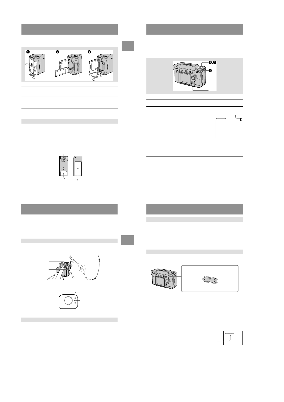
Getting started
Installing the battery pack
Your camera operates only with the “InfoLITHIUM” NP-FM50 battery pack* (M
series). You cannot use any other battery pack.
Battery eject lever
Open the battery/“Memory Stick” cover.
1
Open the cover while sliding the OPEN switch in the direction of the arrow.
Install the battery pack.
2
Insert the battery pack with the B mark facing toward the battery compartment
as illustrated.
Close the battery/“Memory Stick” cover.
3
To remove the battery pack
Open the battery/“Memory Stick” cover. Slide the battery eject lever
downward, and remove the battery pack.
Be careful not to drop the battery pack when removing it.
* What is “InfoLITHIUM”?
“InfoLITHIUM” is a lithium ion battery pack which can exchange information such as battery
consumption with compatible video equipment. This unit is compatible with the
“InfoLITHIUM” battery pack (M series). “InfoLITHIUM” M series battery packs have the
mark. “InfoLITHIUM” is a trademark of Sony Corporation.
Charging the battery pack
You cannot charge the battery pack while your camera is turned on. Be sure to turn
off your camera before charging.
Battery pack (M series)
To the wall outlet (mains)
DC IN jack cover
AC-L10 AC power adaptor
Insert the battery pack into your camera.
1
Open the DC IN jack cover and connect the DC connecting cable to
2
the DC IN jack of your camera with the v mark facing up.
Connect the power cord (mains lead) to the AC power adaptor and
3
then to a wall outlet (mains).
The CHARGE lamp in the display window flashes when charging begins.
When the CHARGE lamp goes off, normal charge is completed. For full
charge, which allows you to use the battery longer than usual, leave the
battery pack inserted for about one hour after normal charge is completed until
the battery remaining indicator and “FULL” is displayed alternately in the
display window.
Battery remaining indicator
The LCD screen on the camera shows the remaining time for which you can still
record or play back images.
This indication may not be entirely accurate depending on the conditions of use and
the operating environment.
Auto power-off function
If you do not operate the camera for about three minutes during recording, the
camera turns off automatically to prevent wearing down the battery. To use the
camera again, slide down the POWER switch to turn on the camera again.
Power cord
(mains lead)
7
Getting started
9
8
Charging time
Battery pack Full charge (min.) Normal charge (min.)
NP-FM50 (supplied) 150 90
Approximate time to charge a completely discharged battery pack using the AC-L10
AC power adaptor.
Battery life and number of images that can be recorded/played back
STILL mode recording*
NP-FM50 (supplied)
LCD screen ON 120 (110) 1600 (1400)
LCD screen OFF 150 (140) 2000 (1800)
STILL mode playback**
LCD screen ON 220 (210) 4400 (4200)
Approximate battery life and number of images that can be recorded/played back
with a fully charged battery pack at a temperature of 77˚F (25˚C), 640×480 image
size and in NORMAL recording mode. Numbers in parentheses indicate the time
when you use a normally charged battery pack.
∗ Recording at about 4-second intervals
∗∗Playing back single images in order at about 3-second intervals
MOVIE mode recording
Continuous recording 150 (140) 130 (120)
Approximate time that can be recorded with a fully charged battery pack at a
temperature of 77˚F (25˚C) and 160×112 image size. Numbers in parentheses
indicate the time when you use a normally charged battery pack.
Battery life (min.) Number of images
NP-FM50 (supplied)
Battery life (min.) Number of images
NP-FM50 (supplied)
LCD screen OFF (min.)
LCD screen ON (min.)
10
1-2

Notes
12
Using the AC power adaptor
Using a car battery
Use Sony DC adaptor/charger.
1
Open the DC IN jack cover and connect the DC connecting cable to
the DC IN jack of your camera with the v mark facing up.
2
Connect the power cord (mains lead) to the AC power adaptor and
then to a wall outlet (mains).
• The battery life and number of images will be decreased if you use your camera at low
temperatures, use the flash, repeatedly turn the power on/off or use the zoom.
• The capacity of the “Memory Stick” is limited. The above figures are a guide when you
continuously record/play back while replacing the “Memory Stick.”
• “----” appears in the display window until the battery usable time is calculated.
• During charging, the indicators in the display window may not appear correctly or may flash in
the following cases.
— When the battery pack is not installed correctly.
— When the AC power adaptor is disconnected.
— When the battery pack has malfunctioned.
• When you turn the LCD screen on and off, it takes about one minute for the correct battery
remaining time to appear.
• If sufficient battery remaining time is indicated but the power runs out soon, fully charge the
battery so that the correct battery remaining time appears.
• Do not short the DC plug of the AC power adaptor with a metallic object, as this may cause
malfunction.
• Do not expose the battery pack to water.
Getting started
DC IN jack cover
AC-L10 AC power adaptor
To the wall outlet (mains)
Power cord
(mains lead)
Setting the date and time
When you first use your camera, set the date and time. If these are not set, the
CLOCK SET screen appears whenever you turn on your camera for recording.
Slide down the POWER switch to turn on the power.
1
The POWER lamp lights up.
Press v on the control button.
2
The menu bar appears on the LCD screen.
Select [SETUP] with B on the control button,
3
then press the center z.
Control button
POWER lamp
11
Getting started
Select [CLOCK SET] with v/V on the control button, then press the
4
center z.
Select the desired date display format with
5
v/V on the control button, then press the
center z.
Select from [Y/M/D] (year/month/day), [M/D/Y]
(month/day/year) or [D/M/Y] (day/month/year).
Select the year, month, day, hour or minute
6
item you want to set with b/B on the control
button.
The item to be set is indicated with v/V.
Set the numeric value with v/V on the control button, then press
7
the center z to enter it.
After entering the number, v/V moves to the next item.
If you selected [D/M/Y] in step 5, set the time on a 24-hour cycle.
Select [ENTER] with B on the control
8
button, then press the center z at the
desired moment to begin clock movement.
The date and time are entered.
13
To cancel the date and time setting
Select [CANCEL] with v/V/b/B on the control button, then press the center z.
14
1-3
Inserting the “Memory Stick”
Access lamp
Open the battery/“Memory Stick” cover.
1
Open the cover while sliding the OPEN switch in the direction of the arrow.
Insert the “Memory Stick.”
2
Insert the “Memory Stick” with the B mark facing toward the battery
compartment as illustrated until it clicks.
Close the battery/“Memory Stick” cover.
3
Removing the “Memory Stick”
Open the battery/“Memory Stick” cover, then press the “Memory Stick” once lightly.
Notes
• Insert the “Memory Stick” firmly until it clicks, otherwise a message such as “MEMORY
STICK ERROR” will be displayed.
• Never remove the “Memory Stick” or turn off the power while the access lamp is lit up.
• You cannot record or edit images on a “Memory Stick” if the erasure prevention switch is set to
the LOCK position.
Erasure prevention switch
ention switch is set to
Connector
Getting started
Basic operations
B Recording
Recording still images
Still images are recorded in JPEG format.
To record still images, slide the POWER switch down to turn on the power and insert
a “Memory Stick.”
POWER switch
Set the MODE selector to STILL.
1
Press and hold the shutter button halfway
2
down and check the image.
While the AE lock indicatorz (green) is flashing,
the image freezes momentarily, but is not yet
recorded. When the camera finishes the automatic
adjustments*, the AE lock indicator z lights up
and the camera is ready for recording.
To cancel the recording, release the shutter button.
Press the shutter button fully down.
3
The shutter sounds and the image is recorded on the “Memory Stick.”
When “REC” disappears, you can record the next image.
∗ Exposure and focus are automatically adjusted.
The number of images you can record on a “Memory Stick”
See pages 38 to 40.
Remaining memory
capacity indicator
AE lock indicator
Label space
15
Notes
• Do not touch the lens portion while it is operating.
• While the image is being recorded on the “Memory Stick,” do not shake or strike the camera.
Also, do not turn the power off, or remove the battery pack or “Memory Stick.”
• When recording a bright subject, the LCD screen color may change after AE lock, b ut this does
not affect the recorded image.
Recording images with the finder
Turn the finder adjustment dial until the image appears clearly within the finder, then
record the image.
Finder adjustment
dial
LCD ON/OFF
Indicators in the finder
To turn off the LCD screen
Press LCD ON/OFF.
Notes
• When you record a subject closer than 3 1/4 feet (1 m), the positions of the finder and the lens
differ, so record using the LCD screen.
• You cannot view digitally zoomed images with the finder. Check these images using the LCD
screen.
• You cannot turn off the LCD screen when [DEMO] or [CONVERSION] are set to [ON] in the
menu settings.
Recording lamp
AE lock lamp
Strobe charge lamp
< Recording
16
Checking the last recorded image (Quick Review)
You can check the last recorded image by clearing the menu bar from the screen
(page 32) and pressing b on the control button. To return to the normal recording
mode, press lightly on the shutter button or select [RETURN] with b/B on the
control button and then press the center z. You can also delete the image first by
selecting [DELETE] on the Quick Review screen with b/B on the control button and
pressing the center z, and then selecting [OK] with v/V on the control button and
pressing the center z.
Using the zoom feature
The lens portion moves during zoom operation. Be careful not to touch the lens
portion while it is operating.
Zoom button
W side: for wide-angle (subject appears
farther away)
T side: for telephoto (subject appears
closer)
Minimum focal distance to the subject
W side: About 9 7/8 inches (25 cm) or more
T side: About 9 7/8 inches (25 cm) or more
To record even closer subjects, see page 41.
Digital zoom function
This camera has a digital zoom function.
Digital zoom enlarges the image by digital processing and it starts to function when
zoom exceeds 3×.
The T side of the bar shows the
digital zooming zone.
Using digital zoom
• The maximum zoom magnification is 6×.
• Digital zooming deteriorates the picture quality. When digital zoom is not
necessary, set [DIGITAL ZOOM] to [OFF] in the menu settings (page 35).
17
18
1-4
Notes
• Zoom does not work while recording moving images.
• Digital zoom does not work for moving images.
• Digitally zoomed images do not appear in the finder.
LCD screen indicators during recording
Press DISPLAY to turn on/off the indicators on the LCD screen.
See page 65 for a detailed description of the indicated items.
< Recording
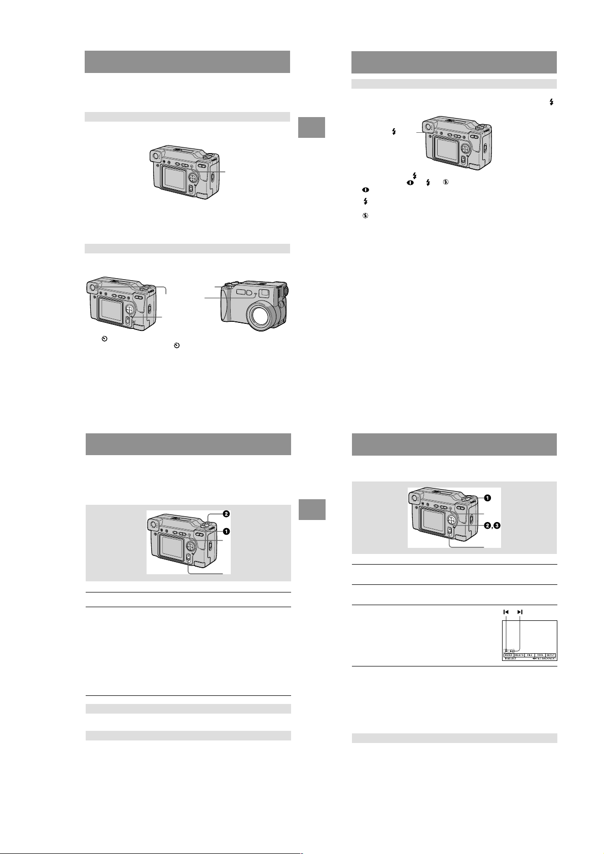
Recording images with the flash
The initial setting is auto (no indicator). In this mode, the flash automatically strobes
when the surroundings become dark. When you change the flash mode, press the
(flash) repeatedly so that the flash mode indicator appears on the LCD screen.
(flash)
DISPLAY
Notes
• You cannot turn off the self-timer indicators and some of the indicators used in advanced
operations.
• The indicators on the LCD screen are not recorded.
Using the self-timer
When you use the self-timer function, the subject is recorded about 10 seconds after
you press the shutter button.
Shutter button
Self-timer lamp
Control button
Select (self-timer) indicator on the LCD screen with v/V/b/B on the control
button, then press the center z. The (self-timer) indicator appears on the LCD
screen, and about 10 seconds after you press the shutter button, the subject is
recorded. The self-timer lamp flashes after you press the shutter button until the
shutter is released.
Recording moving images
Moving images with audio are recorded in MPEG format.
To record moving images, slide the POWER switch down to turn on the power and
insert a “Memory Stick.”
19
Each time you press the (flash), the indicator changes as follows.
(No indicator) t t t t (No indicator)
Auto red-eye reduction: The flash strobes before recording to reduce the
Forced flash: The flash strobes regardless of the surrounding
No flash: The flash does not strobe.
You can change the brightness of the flash (FLASH LEVEL) in the menu settings
(page 35).
Notes
• The recommended shooting distance using the built-in flash is 31/32 feet to 8 1/3 feet (0.3 m to
2.5 m).
• Attaching a conversion lens (not supplied) may block the light from the flash or cause the lens
shadow to appear.
• You cannot use an external flash and the built-in flash at the same time.
• Auto red-eye reduction may not produce the desired red-eye reduction effects depending on
individual differences, the distance to the subject, if the subject does not see the pre-strobe, or
other conditions. In addition, red-eye reduction effects are also difficult to obtain if you set the
shutter to a slow speed in the PROGRAM AE shutter priority mode.
• The flash effect is not obtained easily when you use forced flash in a bright location.
red-eye phenomenon.
brightness.
20
B Playback
Playing back still images
DISPLAY
POWER switch
Set the MODE selector to MOVIE.
1
Press the shutter button fully down.
2
“REC” appears on the LCD screen, and the image and sound are recorded on
the “Memory Stick.”
If you press the shutter button momentarily
The image and sound are recorded for five seconds. You can change the
recording time to 10 or 15 seconds with [REC TIME SET] in the menu settings
(page 34).
If you hold the shutter button down
The image and sound are recorded while the shutter button is held down for up
to 60 seconds. However, when [IMAGE SIZE] in the menu setting is set to
[320 (HQ)]/[320×240], the maximum recording time is 15 seconds (page 34).
Zooming or using the self-timer, etc.
See pages 18 and 19.
LCD screen indicators during recording
Press DISPLAY to turn on/off the indicators on the LCD screen.
These indicators are not recorded. See page 65 for a detailed description of the
indicators.
21
<
Recording
DISPLAY
POWER switch
Set the MODE selector to PLAY.
1
The last recorded image (still or moving) appears on the LCD screen.
Press v on the control button to display the menu bar on the LCD
2
screen.
Select the desired still image with the
3
control button.
Press v/V/b/B on the control button to select "b/B"
on the LCD screen, then press b/B on the control
button.
"b: To display the preceding image.
B": To display the next image.
When the menu bar is not displayed
You can directly select and play back the image with b/B on the control button.
Notes
• You might not be able to correctly play back images recorded with this camera on other
equipment.
• You cannot play back on this camera images larger than the maximum image size that can be
recorded with this camera.
LCD screen indicators during still image playback
Press DISPLAY to turn on/off the indicators on the LCD screen.
See page 65 for a detailed description of the indicators.
22
1-5
Playing back moving images
B (playback)/X (
)
VOLUME +/–
DISPLAY
POWER switch
Set the MODE selector to PLAY.
1
The last recorded image (still or moving) appears on the LCD screen.
Press v on the control button to display the menu bar on the LCD
2
screen.
Select the desired moving image with the
3
control button.
Moving images are displayed one-size smaller than
still images.
Press v/V/b/B on the control button to select "b/B"
on the LCD screen, then press b/B on the control
button.
"b: To display the preceding image.
B": To display the next image.
Select B (playback) on the LCD screen with
4
v/V/b/B on the control button, then press
the center z.
The moving image and sound are played back.
During playback, B (playback) changes to X
(pause).
pause
Playback bar
When the menu bar is not displayed
You can directly select the image with b/B on the control button, and play back the
image and sound by pressing the center z. When you press the center z during
playback, playback is paused.
Moving images recorded with the image of [320 (HQ)]
The images are displayed over the entire screen in steps 3 and 4.
Adjusting the volume
Press VOLUME +/– to adjust the volume.
< Playback
LCD screen indicators during moving image playback
Press DISPLAY to turn on/off the indicators on the LCD screen.
See page 65 for a detailed description of the indicators.
To pause playback
Select X (pause) on the LCD screen with v/V/b/B on the control button, then press
the center z.
23
Viewing images using a personal computer
You can vie w data recorded with your camera on a personal computer and attach it to
e-mail. This section describes the method for installing the USB driver and viewing
images on a personal computer. Be sure to also see the operation manuals for your
personal computer and application software.
Note
Data recorded with your camera is stored in the following formats. Make sure that applications
that support these file formats are installed on your personal computer.
• Still images (other than TEXT and uncompressed modes): JPEG format
• Moving images/audio: MPEG format
• Uncompressed mode still images: TIFF format
• TEXT mode: GIF format
Recommended computer environment
Recommended Windows environment
OS: Microsoft Windows 98, Windows 98SE
Standard installation is required.
Operation is not assured in an environment upgraded from:
Windows
3.1, Windows 95 to Windows 98 or
Windows
CPU: MMX Pentium 200 MHz or faster
The USB connector must be provided as standard.
ActiveMovie Player (DirectShow) must be installed (to play back moving pictures).
Recommended Macintosh environment
Macintosh computer with the Mac OS 8.5.1/8.6/9.0 standard installation
However, note that the update to Mac OS 9.0 should be used for the following models.
The USB connector must be provided as standard.
QuickTime 3.2 or newer must be installed (to play back moving pictures).
Notes
• Operations are not guaranteed for either the W indo ws or Macintosh environment if you connect
two or more USB equipment to a single personal computer at the same time (except for the
USB keyboard and mouse which are provided as standard), or when using a hub.
• Depending on the type of USB equipment that is used simultaneously, some equipment may
not operate.
• Operations are not guaranteed for all the recommended computer environments mentioned
above.
98 to Windows 98SE.
• iMac with the Mac OS 8.6 standard installation and a slot loading type CD-ROM drive
• iBook or G4 with the Mac OS 8.6 standard installation
24
Installing the USB driver
Before connecting your camera to your personal computer, install the USB driver to
the computer. The USB driver is contained together with application software for
viewing images on a CD-ROM which is supplied with your camera.
For Windows 98 users
Turn on your personal computer and allow Windows 98 to load.
1
Insert the supplied CD-ROM in the CD-ROM drive of your personal
2
computer.
< Playback
Connect the USB jack on your camera with the USB connector on
3
your personal computer using the supplied USB cable.
USB cable
to the USB jack
Push in until the
connector clicks
into place
to the USB connector
Personal computer
Insert a “Memory Stick” into your camera, connect the AC power
4
adaptor and turn on your camera.
“PC MODE” appears on the LCD screen of your camera and the camera is set
to communication standby mode. Your personal computer recognizes the
camera, and the Windows 98 Add Hardware Wizard starts.
Follow the on-screen messages to specify the CD-ROM drive and
5
install the USB driver.
The Add Hardware Wizard starts twice because two different USB drivers are
installed. Be sure to allow the installation to complete without interrupting it.
Note
Be sure to insert a “Memory Stick” into your camera before installing the USB driver.
Otherwise, you will be unable to install the USB driver.
For Macintosh users
Turn on your personal computer and allow the Mac OS to load.
1
Insert the supplied CD-ROM in the CD-ROM drive of your personal
2
computer.
25
26
1-6

Double-click the CD-ROM drive icon to open the window.
30
Advanced operations
Before performing advanced operations
This section describes the basic control methods that are frequently used for
“Advanced operations”.
How to use the MODE selector
The MODE selector selects whether you can use your camera to record or to play
back and edit images. Set the selector as follows before starting to operate your
camera.
How to use the control button
The control button is used to select the indicators, images and menus appearing on
the LCD screen of your camera. The operation methods that are frequently used for
“Advanced operations” are described below.
3
Double-click the icon of the hard disk containing the OS to open
4
the window.
Move the following two driver files from the window opened in step
5
3 to the “System Folder” icon in the window opened in step 4
(drag and drop).
• Sony USB Driver
• Sony USB Shim
When “Put these items into the Extensions folder?” appears, click
6
“OK.”
Restart your personal computer.
7
Viewing images
For Windows 98 users
Turn on the power of your personal computer and allow
1
Windows 98 to load.
Connect one end of the USB cable to the USB jack on the camera
2
and the other end to the USB connector on your personal
computer.
to the USB connector
Personal computer
Insert a “Memory Stick” into your camera, and connect the AC
3
power adaptor to your camera and then to a wall outlet (mains).
Turn on the power of your camera.
4
“PC MODE” appears on the LCD screen of the camera.
Open “My Computer” on Windows 98 and double click the newly
5
recognized drive. (Example: “Removable Disk (D:)”)
The folders inside the “Memory Stick” are displayed.
USB cable
to the USB jack
Push in until the
connector clicks
into place
Select and double-click the desired image/sound file from the
6
folder.
For the detailed folder and file name, see “Image file storage destinations and
image files” (page 29).
Desired file type Double-click in this order
Still image “Dcim” folder t “100msdcf” folder t Image file
Moving image* “Mssony” folder t “Moml0001” folder t Image file*
Audio* “Mssony” folder t “Momlv100” folder t Audio file*
E-mail image
TIFF image
< Playback
(uncompressed)
∗ Copying a file to the hard disk of your personal computer before viewing it is
recommended. If you play back the file directly from the “Memory Stick”, the image
and sound may break off.
“Mssony” folder t “Imcif100” folder t Image file
Notes on using your personal computer
“Memory Stick”
• “Memory Stick” operations on your camera cannot be assured if the “Memory Stick” has been
formatted on your personal computer.
• Do not optimize the “Memory Stick” on a Windows machine. This will shorten the “Memory
Stick” life.
• Do not compress the data on the “Memory Stick.” Compressed files cannot be played back on
your camera.
Software
• Depending on your application software, the file size may increase when you open a still image
file.
• When you load an image modified using the supplied retouch software from your personal
computer to the camera or when you directly modify the image on the camera, the image
format will differ so the “FILE ERROR” message may appear and you may be unable to open
the file.
Communications with your personal computer
Communications between your camera and your personal computer may not recover after
recovering from Suspend, Resume, or Sleep.
• Windows and ActiveMovie, DirectShow are either registered trademarks or trademarks of
Microsoft Corporation in the United States and/or other countries.
• Macintosh and Mac OS, QuickTime are trademarks of Apple Computer, Inc.
• All other product names mentioned herein may be the trademarks or registered trademarks of
their respective companies. Furthermore, “™” and “®” are not mentioned in each case in this
manual.
Image file storage destinations and image
files
Image files recorded with your camera are grouped in folders by recording mode.
The meanings of the file names are as follows. ssss stands for any number
within the range from 0001 to 9999.
For Windows 98 users (The drive recognizing the camera is “D.”)
Folder containing still image data
Folder containing E-MAIL mode and TIFF
mode image data
Folder containing moving image data
Folder containing VOICE mode audio data
Folder File Meaning
100msdcf DSC0ssss.JPG • Still image file recorded normally
TXT0ssss.GIF • Still image file recorded in TEXT mode
Imcif100 DSC0ssss.JPG • Small-size image file recorded in E-
DSC0ssss.TIF • Uncompressed image file recorded in
Moml0001 MOV0ssss.MPG • Moving image file recorded normally
Momlv100 DSC0ssss.MPG • Audio file recorded in VOICE mode
The numerical portions of the following files are the same.
— A small-size image file recorded in E-MAIL mode and its corresponding image file
— An uncompressed image file recorded in TIFF mode and its corresponding image file
— An audio file recorded in VOICE mode and its corresponding image file
• Still image file recorded in E-MAIL
mode (page 39)
• Still image file recorded in TIFF mode
(page 40)
• Still image file recorded in VOICE
mode (page 39)
(page 40)
MAIL mode (page 39)
TIFF mode (page 40)
(page 39)
27
28
< Playback
PLAY: To play back or edit
images
STILL: To record still images
and voice memos
MOVIE: To record moving
images
Select Enter (OK)
29
1-7

Turning on/off the operation buttons (menu bar) on the LCD screen
Press v to display the menu bar
on the LCD screen.
How to change the menu settings
Some of the advanced operations for your camera are executed by selecting menu
items displayed on the LCD screen with the control button.
Press V to clear the menu bar
from the LCD screen.
Note
You cannot clear the menu bar during INDEX screen display (page 45).
Selecting items and images on the LCD screen
Press v/V/b/B on the
1
control button to select the
item you want to set or the
image you want to display.
The color of the selected item or
the border of the selected image
changes from blue to yellow.
Press the center z
2
the item.
Repeat steps 1 and 2 to execute
each function.
The “Advanced operations” section of this manual refers to selecting and
entering items by the above procedure as “Select [(item name)].”
to enter
Menu bar
Before performing advanced operations
31
MODE selector
Press v on the control button to display the menu bar.
1
The menu bar appears as follows according to the setting of the MODE
selector.
MOVIE/STILL PLAY (single mode) PLAY (INDEX mode)
,
Select the desired item with v/V/b/B on the
2
control button, then press the center z.
The color of the selected item changes from blue to
yellow, and when you press the center z, the modes
that can be set for that item are displayed.
Select the desired mode with v/V/b/B on the control button, then
3
press the center z.
To clear the menu
Press V on the control button until the LCD screen returns to the menu bar display in
step 1. To clear the menu bar, press V again.
32
Menu settings
Menu items that can be modified differ depending on the setting of the MODE
selector. The LCD screen shows only the items you can operate at the moment. Initial
settings are indicated with x.
(SELF TIMER)
Records with the self-timer (page 19).
EFFECT
Item Setting Description MODE
P.EFFECT SOLARIZE
DATE/
TIME
FILE
FORMAT OK Formats a “Memory Stick.” MOVIE
POS.
SENSOR
FILE
NUMBER
B&W
SEPIA
NEG.ART
x OFF
DAY&TIME
DATE
x OFF
Item Setting Description MODE
CANCEL Cancels formatting of a “Memory
ON Plays back images recorded with the
x OFF When this camera may be subject to
SERIES Assigns numbers to files in sequence
x NORMAL Resets the file numbering each time the
Sets the image special effects (page 44). MOVIE
Sets whether to insert the date and time
into the image (page 44).
Stick.”
camera on its side (vertical images) as
horizontal images. This function does
not work for images recorded in TEXT
mode.
vibration such as when you record
images from inside a moving car, set
this to OFF to prevent improper
horizontal/vertical judgement.
even if the “Memory Stick” is changed.
“Memory Stick” is changed.
selector
STILL
STILL
selector
STILL
PLAY
STILL
MOVIE
STILL
Before performing advanced operations
Item Setting Description MODE
IMAGE
SIZE
REC MODE TIFF Records a TIFF (uncompressed) file in
REC TIME
SET
ROTA TE
(in single
mode only)
SLIDE
SHOW
(in single
mode only)
PRINT
MARK
PROTECT ON Protects images against accidental
x 2048×1536
2048 (3:2)
1600×1200
1280×960
640×480
320 (HQ)
320×240
x 160×112
TEXT Records a GIF file in black-and-white.
VOICE Records an audio file (with still image)
E-MAIL Records a small-size (320×240) JPEG
x NORMAL Records a JPEG file in the selected
15 SEC
10 SEC
x 5 SEC
INTERVAL
REPEAT Repeats the slide show.
START Starts the slide show.
CANCEL Cancels the slide show settings and
ON Marks the still images to be printed
x OFF Unmarks the print mark of the still
x OFF Releases protection of images against
Selects the image size when recording
still images.
Selects the MPEG image size when
recording moving images.
addition to the JPEG file.
in addition to the JPEG file.
file in addition to the selected image
size.
image size.
Adjusts the recording time for moving
images.
Rotates the still image. PLAY
—
Sets the slide show interval.
x 3 SEC/5 SEC/10 SEC/30 SEC/1 MIN
x ON/OFF
execution.
(page 53).
images.
erasure (page 49).
accidental erasure.
selector
STILL
MOVIE
STILL
MOVIE
PLAY
PLAY
PLAY
33
34
1-8
CAMERA
Item Setting Description MODE
CONVERSION
DIGITAL
ZOOM
SHARPNESS
WHITE
BALANCE
FLASH
LEVEL
EXPOSURE +2.0 EV to
TOOL
COPY OK Copies an image (page 51). PLAY
RESIZE
(in single
mode only)
ON Set to “ON” when using the VCL-
x OFF
x ON Uses digital zoom. STILL
OFF Does not use digital zoom.
+2 to –2 Adjusts the sharpness of the image.
IN DOOR
OUT DOOR
HOLD
x AUTO
HIGH Makes the flash level higher than
x NORMAL Normal setting.
LOW Makes the flash level lower than normal.
–2.0 EV
Item Setting Description MODE
CANCEL Cancels copying of the image.
2048×1536
1600×1200
1280×960
640×480
x CANCEL
MHG07 conversion lens (not supplied).
At this time, the zoom function does not
work and you cannot turn off the LCD
screen.
Also, note that the VAD-S70 adaptor
ring needed to mount the conversion
lens to your camera is not sold in some
countries and regions.
appears on the LCD screen except
when set to 0.
Sets the white balance (page 43). MOVIE
normal.
Adjusts the exposure. MOVIE
Changes the recorded still image size
(page 51).
MOVIE
STILL
STILL
STILL
STILL
STILL
PLAY
selector
selector
Before performing advanced operations
SETUP
Item Setting Description MODE
DEMO xON/STBY
VIDEO
OUT
LANGUAG
E
CLOCK
SET
BEEP SHUTTER Turns off the beep only. (The shutter
LCD
BRIGHT
INDEX*
Displays six images at a time (PLAY (INDEX) mode) (page 45).
DELETE
OK Deletes the displayed image. PLAY
CANCEL Cancels deleting of the image.
OFF
x NTSC Sets the video output signal to NTSC
PAL Sets the video output signal to PAL
/
x ENGLISH Displays the menu items in English. MOVIE
x ON Turns on the beep/shutter sound (when
OFF Turns off the beep/shutter sound.
Setting Description MODE selector
Displayed only when you use the AC
power adaptor in MOVIE or STILL
mode. When ON is selected, a
demonstration will start if you do not
operate your camera for about
10 minutes. To stop the demonstration,
turn off your camera. Select ON to make
the demonstration appear again.
mode (North American countries, Japan,
etc.).
mode (European countries, etc.).
/JPN Displays the menu items in Japanese.
Sets the date and time (page 13). MOVIE
—
sound is heard when you press the
shutter button.)
you press the control button/
button).
Adjusts the LCD screen brightness
using the +/– buttons on the LCD
screen. This has no effect on the
recorded images.
shutter
selector
MOVIE
STILL
MOVIE
STILL
PLAY
STILL
PLAY
STILL
PLAY
MOVIE
STILL
PLAY
MOVIE
STILL
PLAY
3 (RETURN)**
Returns to PLAY (single) mode.
∗ Displayed only in PLAY (single) mode.
∗∗Displayed only in PLAY (INDEX) mode.
35
Before performing advanced operations
36
B
V arious recor ding
Setting the image size
(IMAGE SIZE)
1
Set the MODE selector to
MOVIE or STILL.
2
Select [FILE] and then
[IMAGE SIZE] from the menu.
3
Select the desired image
size.
Still image sizes
2048×1536, 2048 (3:2),
1600×1200, 1280×960, 640× 480
Moving image sizes
320 (HQ*), 320×240, 160× 112
∗ High Quality mode
The number of images or the time
that you can record on a “Memory
Stick” (8 MB):
Image size Number of images or
2048×153
6
2048 (3:2) Approx. 5
1600×120
0
1280×960 Approx. 12
640×480 Approx. 118
320 (HQ) Approx. 20 (15**) sec.
320×240 Approx. 85 (15**) sec.
160×112
time*
Approx. 5
Approx. 8
Approx. 345 (60**) sec.
∗ When [REC MODE] is set to
[NORMAL].
∗∗Numbers in parentheses indicate the
maximum recording time during
continuous recording.
When [2048 (3:2)] is selected
The image is recorded in 3:2 size to
match the printing paper size ratio of
3:2.
37
38
1-9

Recording still images for email (E-MAIL)
E-MAIL mode records a small-size
(320×240) image at the same time as a
still image. Small-size images are
convenient for e-mail transmission,
etc.
1
Set the MODE selector to
STILL.
2
Select [FILE], [REC MODE],
and then [E-MAIL] from the
menu.
3
Record the image.
The number of images that you can
record on a “Memory Stick” (8 MB)
in E-MAIL mode.
Image size Number of images
2048×1536 Approx. 4
2048 (3:2) Approx. 4
1600×1200 Approx. 8
1280×960 Approx. 12
640×480 Approx. 95
To return to normal recording mode
Select [NORMAL] in step 2.
Adding audio files to still
images (VOICE)
1
Set the MODE selector to
STILL.
2
Select [FILE], [REC MODE],
and then [VOICE] from the
menu.
3
Record the image.
If you press and release the shutter
button, sound is recorded for
5 seconds.
If you hold down the shutter
button, sound is recorded until you
release the shutter button for up to
40 seconds.
The number of images that you can
record on a “Memory Stick” (8 MB)
in VOICE mode (when recording
sound for five seconds):
Image size Number of images
2048×1536 Approx. 4
2048 (3:2) Approx. 4
1600×1200 Approx. 7
1280×960 Approx. 11
640×480 Approx. 56
To return to normal recording mode
Select [NORMAL] in step 2.
< Various recording
Recording text documents
(TEXT)
Text is recorded in black and white
GIF format to provide a clearer image.
1
Set the MODE selector to
STILL.
2
Select [FILE], [REC MODE],
and then [TEXT] from the
menu.
3
Record the image.
The number of images that you can
record on a “Memory Stick” (8 MB)
in TEXT mode:
Image size Number of images
2048×1536 Approx. 15 to 125
2048 (3:2) Approx. 17 to 137
1600×1200 Approx. 25 to 137
1280×960 Approx. 40 to 228
640×480 Approx. 160 to 727
To return to normal recording mode
Select [NORMAL] in step 2.
Notes
• If the subject is not evenly illuminated, you
may be unable to record a clear image.
• Writing and reading data takes more time
than in normal recording.
Recording uncompressed
images (TIFF)
This mode simultaneously records still
images in both TIFF format
(uncompressed) and JPEG format
(compressed).
1
Set the MODE selector to
STILL.
2
Select [FILE], [REC MODE],
and then [TIFF] from the
menu.
3
Record the image.
The number of images that you can
record on a “Memory Stick”
(16 MB) in TIFF mode:
Image size Number of images
2048×1536 Approx. 1
2048 (3:2) Approx. 1
To return to normal recording mode
Select [NORMAL] in step 2.
Notes
• JPEG images are recorded in the image
size selected by the [IMAGE SIZE] menu.
TIFF images are recorded in [2048
size other than when [2048 (3:2)] is
selected.
• Writing data takes more time than in
normal recording.
• The supplied “Memory Stick” (8 MB)
does not have sufficient capacity to record
uncompressed images.
×1536]
Recording images in macro
1
Set the MODE selector to
MOVIE or STILL.
2
Press FOCUS repeatedly
until the (auto macro)
indicator appears on the LCD
screen.
You can record a subject as close
as about 1 5/8 inches (4 cm) from
the lens surface with the zoom set
all the way to the W side, or about
8 inches (20 cm) with the zoom set
all the way to the T side.
To return to normal recording mode
Press FOCUS repeatedly until
disappears from the LCD screen.
Notes
• You cannot record images in macro with
the following PROGRAM AE modes.
— Landscape mode
— Panfocus mode
• When recording images in macro, use the
LCD screen. If you record using the finder,
the range visible in the finder may differ
from the actual recording range.
• You cannot record images in macro when
appears on the LCD screen.
39
Setting the distance to the
subject
Normally the focus is automatically
adjusted. This function is useful when
the auto focus does not work well such
as in dark places.
1
Set the MODE selector to
MOVIE or STILL.
2
Press FOCUS repeatedly to
achieve a sharp focus.
The 9 (manual focus) indicator
appears on the LCD screen.
You can select from the following
7 focus settings: auto (no
indicator), (auto macro),
1 3/4 feet (0.5m), 3 1/4 feet
(1.0m), 9 3/4 feet (3.0m), 23 feet
(7.0m), ∞ (infinite)
To reactivate auto focusing
Press FOCUS repeatedly until the
indicator disappears in step 2.
Notes
• These setting distances are approximate,
and should be used as a reference.
• The focus mode indicator is not displayed
correctly when using a conversion lens.
41
< Various recording
40
Using the PROGRAM AE
function
+/–
1
Set the MODE selector to
MOVIE or STILL.
2 Press PROGRAM AE
repeatedly to select the
desired PROGRAM AE mode.
A Aperture priority mode
Makes the subject stand out
against an unclear background or
makes both the subject and the
background stand out clearly.
Press +/– repeatedly to select an
aperture value in 9 steps from F2.0
to F8.0.
S Shutter speed priority
mode
Records a sharp picture of a fastmoving subject or the flow of
motion of a moving subject.
Press +/– repeatedly to select a
shutter speed in 19 steps from 8”
to 1/1000 when recording a still
image and in 13 steps from 1/8 to
1/1000 when recording a moving
image.
Twilight mode
Suppresses the washed-out color
of a bright subject in a dark place
so that you can record the subject
without losing the dark
atmosphere of the surroundings.
Twilight plus mode
Increases the effectiveness of the
twilight mode function.
42
Landscape mode
Focuses only on a distant subject
to record landscapes, etc.
Panfocus mode
Changes the focus quickly and
simply from a close subject to a
distant subject.
Spot light-metering mode
Select this mode when there is
backlight or when there is strong
contrast between the subject and
the background, etc. Position the
point you want to record on the
spot light-metering cross hair.
LCD screen
Spot light-metering
cross hair
To cancel PROGRAM AE
Press PROGRAM AE repeatedly until
the indicator on the LCD screen goes
out.
Notes
• When you set the zoom to the T side, the
value in aperture indicator may differ from
the actual aperture.
• You can focus only on distant subjects in
Landscape mode.
• In Panfocus mode, the zoom position and
focus are fixed.
• When you record in the Twilight plus
mode, we recommend that you use a tripod
to prevent shaking.
• Set the forced flash when you use the
flash in the following modes:
–Twilight mode
–Twilight plus mode
–Landscape mode
• You cannot use the PROGRAM AE
function when [REC MODE] is set to
[TEXT].
• If the setting is not appropriate in aperture
priority mode and shutter priority mode,
the setting value indicator on the LCD
screen flashes when you press the shutter
button. In this case, reset the value.
1-10
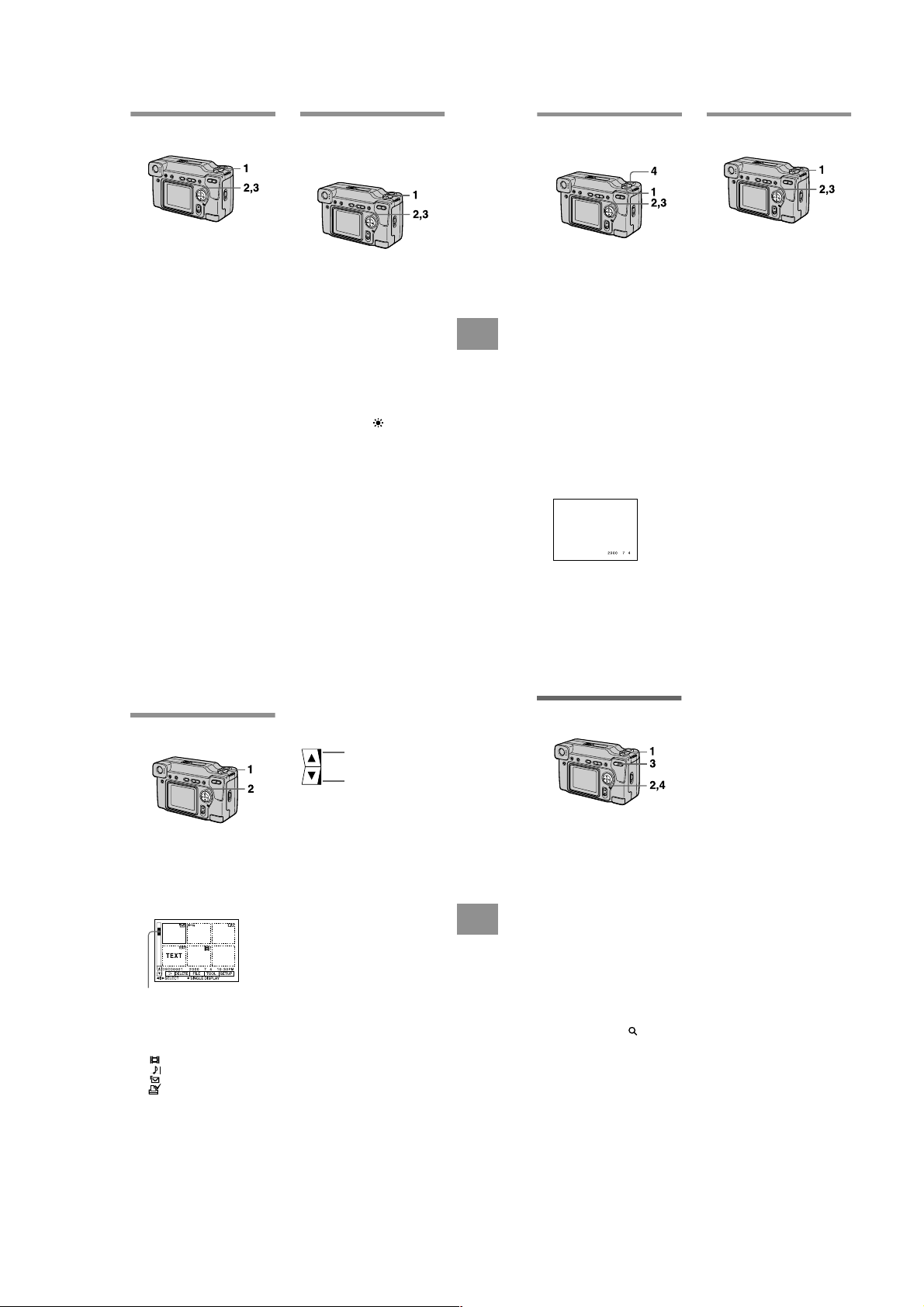
Adjusting the exposure
46
Enlarging a part of the still
image (Zoom and trimming)
1
Set the MODE selector to
PLAY.
2
Display the image to be
enlarged.
3
Zoom in/out the image with
the zoom button.
The zoom scaling indicator
appears on the LCD screen.
4
Press the control button
repeatedly to select the
desired part of the image.
v: The image moves downward
V: The image moves upward
b: The image moves rightward
B: The image moves leftward
To return to the normal size
Zoom in with the zoom button until the
zoom scaling indicator ( × 1.1)
disappears from the screen, or simply
press z.
To record an enlarged image
(trimming)
1Enlarge the image.
2Press the shutter button. The image
is recorded at 640×480 size, then the
display returns to the image display
before enlargement.
Notes
• You cannot trim images recorded in TEXT
mode or uncompressed images.
• The maximum zoom magnification is 5
×
the original image, regardless of the image
size.
• The picture quality of trimmed images
may deteriorate.
• The original picture remains even after
trimming.
• The trimmed image is recorded as the
newest file.
(EXPOSURE)
1
Set the MODE selector to
MOVIE or STILL.
2
Select [CAMERA] and then
[EXPOSURE] from the menu.
3
Select the desired exposure
value.
Adjust the exposure value while
checking the brightness of the
background. You can select values
ranging from +2.0 EV to –2.0 EV
in steps of 1/3 EV.
Note
The exposure may not be adjusted properly
when the subject is extremely bright or dark,
or when using the flash.
Adjusting the white balance
(WHITE BALANCE)
Normally the white balance is
automatically adjusted.
1
Set the MODE selector to
MOVIE or STILL.
2
Select [CAMERA] and then
[WHITE BALANCE] from the
menu.
3
Select the desired white
balance setting.
IN DOOR (n)
• Places where the lighting
condition changes quickly
• Under bright lighting such as
photography studios
• Under sodium or mercury lamps
OUT DOOR ( )
Recording a sunrise/sunset, night
scene, neon signs, or fireworks
HOLD
Recording a single-colored subject
or background
AUTO (No indicator)
Adjusts the white balance
automatically
To reactivate auto adjustment
Select [AUTO] in step 3.
Note
Select [AUTO] when recording under
fluorescent lighting.
< Various recording
Recording the date and time
on the still image (DATE/
TIME)
1
Set the MODE selector to
STILL.
2
Select [EFFECT] and then
[DATE/TIME] from the menu.
3
Select the date and time
setting.
DAY&TIME
The date, hour and minutes are
imposed onto the image.
DATE
The year, month and day are
imposed onto the image.
OFF
The date and time are not imposed
onto the image.
4
Record the image.
The date and time are not
displayed during recording.
The date and time are displayed
when playing back images.
Enjoying picture effects
(P.EFFECT)
1
Set the MODE selector to
MOVIE or STILL.
2
Select [EFFECT] and then
[P.EFFECT] from the menu.
3
Select the desired mode.
SOLARIZE
The light contrast is clearer and the
picture looks like an illustration.
B&W
The picture is monochrome (black
and white).
SEPIA
The picture is colored like an old
picture.
NEG.ART
The color and brightness of the
picture are reversed.
To cancel picture effect
Select [OFF] in step 3.
B
V arious playback
Playing back six images at
once (INDEX)
1
Set the MODE selector to
PLAY.
2
Select [INDEX] on the LCD
screen.
Six images are displayed at once
(index screen).
This shows the position of the
currently displayed images relative
to all the recorded images.
The following marks are displayed
on each image according to the
image type and settings.
- : Protect mark
TEXT: T ext mark
TIFF: TIFF mark
(No mark): Normal recording (no
settings)
: Moving image file
: V oice memo file
: E-mail file
: Print mark
43
To display the next (previous) index
screen
Select v/V at the lower left of the LCD
screen.
Displays the previous
index screen
Displays the next index
screen
To return to normal playback (single
image)
• Select the desired image with the
control button.
• Select [3] (RETURN).
Note
You cannot display images recorded in
TEXT mode on the INDEX screen.
45
44
< Various playback
1-11

Rotating a still image
(ROTATE)
1
Set the MODE selector to
PLAY.
2
Display the image to rotate.
3
Select [FILE] and then
[ROTATE] from the menu.
Rotate the image clockwise
4
or counterclockwise ,
then select [RETURN].
Notes
• You may not be able to rotate protected
images or images recorded with other
equipment.
• Also, when viewing images on a personal
computer, the image rotation information
may not be reflected depending on the
application software.
• You cannot rotate protected or
uncompressed images, or images recorded
in TEXT mode.
Playing back the images in
order (SLIDE SHOW)
This function is useful for checking the
recorded images or for presentations,
etc.
Set the MODE selector to
1
PLAY.
Select [FILE] and then [SLIDE
2
SHOW] from the menu.
Set the following items.
INTERVAL
1 MIN (one minute), 30 SEC
(30 seconds), 10 SEC
(10 seconds), 5 SEC (5 seconds),
3 SEC (3 seconds)
REPEAT
ON: Plays back images in a
continuous loop until
[RETURN] is selected.
OFF: After all images have been
played back, the slide show
ends.
3
Select [START] with the
control button.
The slide show begins.
To cancel the slide show
Select [CANCEL] in step 2 or 3.
To skip to the next/previous image
during slide show playback
"b/B"
Select
LCD screen.
at the lower left of the
< Various playback
Note
The [INTERVAL] setting time is
approximate, and may vary depending on
the played back image size or other factors.
Viewing images on a TV
screen
Before connecting your camera, be
sure to turn off the TV.
Set the TV/VIDEO
switch to “VIDEO.”
A/V connecting cable
to A/V OUT jack
1
Connect the A/V connecting
cable to the A/V OUT jack of
your camera and to the
audio/video input jacks of the
TV.
If your TV has stereo type audio
input jacks, connect the audio plug
of the A/V connecting cable to the
Lch jack.
Turn on the TV, then start
2
playback on your camera.
The playback image appears on
the TV screen.
Note
You cannot use a TV that has an antenna
(aerial) connector only.
B
Editing
Preventing accidental erasure
(PROTECT)
The - (protect) indicator appears on
protected images.
In single mode
Set the MODE selector to
1
PLAY, then display the image
to protect.
2
Select [FILE], [PROTECT],
and then [ON] from the menu.
The displayed image is protected
and - appears.
To release protection
Select [OFF] in step 2.
In INDEX mode
1
Set the MODE selector to
PLAY, then display the INDEX
screen.
Select [FILE], [PROTECT],
2
and then [ALL] or [SELECT]
from the menu.
3
When you select [ALL]
Select [ON].
All the images recorded in
“Memory Stick” are protected.
When you select [SELECT]
Select all the images to protect
with the control button, then select
[ENTER].
The selected images are protected.
To release protection
If you selected [ALL] in step 2, select
[OFF]. If you selected [SELECT] in
step 2, select the images to unprotect
with the control button, then select
[ENTER].
47
< Editing
48
Deleting images (DELETE)
You cannot delete protected files.
In single mode
1
Set the MODE selector to
PLAY, then display the image
to delete.
2
Select [DELETE] and then
[OK] from the menu.
The image is deleted.
In INDEX mode
1
Set the MODE selector to
PLAY, then display the INDEX
screen.
2
Select [DELETE] and then
[ALL] or [SELECT] from the
menu.
3
When you select [ALL]
Select [ENTER].
All unprotected images are
deleted.
When you select [SELECT]
Select all the images to delete with
the control button, then select
[ENTER].
The (delete) indicator appears
on the selected images and these
images are deleted.
To cancel deleting
Select [CANCEL] in step 2 or 3.
Note
If there are files on the “Memory Stick” with
names having the same last 4 digits as the
file name of the image to be deleted, these
files are also deleted at the same time.
49
50
1-12
Changing the recorded still
52
1
Set the MODE selector to
PLAY, then display the INDEX
screen.
2
Select [TOOL], [COPY], and
then [SELECT] from the
menu.
3
Select the image to copy.
The (select) indicator appears
on the image.
4
Select [ENTER].
“MEMORY STICK ACCESS”
appears.
5
When “CHANGE MEMORY
STICK” is displayed, eject the
“Memory Stick.”
“INSERT MEMORY STICK”
appears.
6
Insert another “Memory
Stick.”
“RECORDING” appears. When
copying is completed,
“COMPLETE” appears.
To end copying, select [EXIT].
To copy the image to another “Memory
Stick”
Select [CONTINUE] after step 6 and
insert a new “Memory Stick.”
To cancel copying part-way
Change the MODE selector setting or
turn off the power.
In INDEX mode
Notes
• If you do not select [EXIT] after
“COMPLETE” appears and instead insert
a new “Memory Stick,” the same image is
copied again.
• You cannot copy uncompressed images.
• You cannot copy images that are bigger
than 5 MB at once. If “NOT ENOUGH
MEMORY” appears or flashes on the
INDEX screen, cancel some images to
copy and try again.
image size (RESIZE)
1
Set the MODE selector to
PLAY and display the image
to resize.
2
Select [TOOL] and then
[RESIZE] from the menu.
3
Select the desired image
size.
2048×1536, 1600×1200,
×
1280 960, 640×480
The changed image is recorded,
then the display returns to the
image display before resizing.
To return to the original size
Select [CANCEL] in step 3.
Notes
• You cannot change the size of images
recorded in TEXT mode or uncompressed
images.
• When you change from a small size to a
large size, the picture quality deteriorates.
• The original image is retained even after
resizing.
• The resized image is recorded as the
newest file.
Copying images (COPY)
You can copy images to another
“Memory Stick.”
In single mode
Set the MODE selector to
1
PLAY, then display the image
to copy.
2
Select [TOOL], [COPY], and
then [OK] from the menu.
“FILE ACCESS” appears.
When “CHANGE MEMORY
3
STICK” appears, eject the
“Memory Stick.”
“INSERT MEMORY STICK”
appears.
Insert the “Memory Stick” on
4
which to copy the image.
“RECORDING” appears. When
copying is completed,
“COMPLETE” appears.
To end copying, select [EXIT].
To copy the image to another “Memory
Stick”
Select [CONTINUE] after step 4 and
insert a new “Memory Stick.”
Notes
If you do not select [EXIT] after
“COMPLETE” appears and instead insert a
new “Memory Stick,” the same image is
copied again.
< Editing
Selecting still images to print
(PRINT MARK)
You can mark a print mark on still
images recorded with your camera.
This mark is convenient when you
have images printed at a shop that
conforms with the DPOF (Digital Print
Order Format) standard.
In single mode
1
Set the MODE selector to
PLAY and display the image
you want to print.
Select [FILE], [PRINT MARK],
2
and then [ON] from the menu.
The (print) mark is displayed
on the image.
To unmark the print mark
Select [OFF] in step 2.
In INDEX mode
1
Set the MODE selector to
PLAY, then display the INDEX
screen.
2
Select [FILE], [PRINT MARK],
and then [SELECT] from the
menu.
3
Select the images to mark
with the control button.
4
To unmark selected print marks
Select the images to unmark in step 3
with the control button, then select
[ENTER].
To unmark all the print marks
Select [FILE], [PRINT MARK],
[ALL] and then [OFF] from the menu.
Notes
• You cannot mark moving images or
images recorded in TEXT mode.
• If you mark an image recorded in TIFF
mode with a print mark, only the
uncompressed image is printed, and the
JPEG image recorded at the same time is
not printed.
Select [ENTER].
of the selected images change
from green to white.
of all images are unmarked.
51
53
< Editing
Additional information
Precautions
On cleaning
Cleaning the LCD screen
Wipe the screen surface with a cleaning
cloth (not supplied) or a LCD cleaning kit
(not supplied) to remove fingerprints, dust,
etc.
Cleaning the camera surface
Clean the camera surface with a soft cloth
slightly moistened with water, then wipe the
surface dry. Do not use any type of solvent
such as thinner, alcohol or benzene as this
may damage the finish or the casing.
After using your camera at the
seashore or other dusty locations
Clean your camera carefully. Otherwise, the
salty air may corrode the metal fittings or
dust may enter the inside of your camera,
causing a malfunction.
Note on operating
temperature
Your camera is designed for use between the
temperatures of 32˚F and 104˚F (0˚C and
40˚C). Recording in extremely cold or hot
places that exceed this range is not
recommended.
On moisture condensation
If the camera is brought directly from a cold
to a warm location, or is placed in a very
damp room, moisture may condense inside
or outside the camera. Should this occur, the
camera will not operate properly.
Moisture condensation occurs
easily when:
• The camera is brought from a cold location
such as a ski slope into a warmly heated
room.
• The camera is taken from an airconditioned room or car interior to the hot
outdoors, etc.
54
How to prevent moisture
condensation
When bringing the camera from a cold place
to a warm place, seal the camera in a plastic
bag and allow it to adapt to conditions at the
new location over a period of time (about an
hour).
If moisture condensation occurs
Turn off the camera and wait about an hour
for the moisture to evaporate. Note that if
you attempt to record with moisture
remaining inside the lens, you will be
unable to record clear images.
On AC power adaptor
• Unplug the unit from the wall outlet
(mains) when you are not using the unit for
a long time.
• T o disconnect the po wer cord (mains lead),
pull it out by the plug. Never pull the
power cord (mains lead) itself.
• Do not operate the unit with a damaged
cord or if the unit has been dropped or
damaged.
• Do not bend the power cord (mains lead)
forcibly, or place a heavy object on it. This
will damage the cord and may cause fire or
electrical shock.
• Prevent metallic objects from coming into
contact with the metal parts of the
connecting section. If this happens, a short
may occur and the unit may be damaged.
• Always keep metal contacts clean.
• Do not disassemble the unit.
• Do not apply mechanical shock or drop the
unit.
• While the unit is in use, particularly during
charging, keep it away from AM receivers
and video equipment. AM reception and
video operation are disturbed.
• The unit becomes warm during use. This is
not a malfunction.
• Do not place the unit in locations that are:
—Extremely hot or cold
—Dusty or dirty
—Very humid
—Vibrating
1-13
On battery pack
• Use only the specified charger with the
charging function.
• T o pre vent accident from a short circuit, do
not allow metal objects to come into
contact with the battery terminals.
• Keep the battery pack away from fire.
• Never expose the battery pack to
temperatures above 140˚F (60˚C), such as
in a car parked in the sun or under direct
sunlight.
• Keep the battery pack dry.
• Do not expose the battery pack to any
mechanical shock.
• Do not disassemble nor modify the battery
pack.
• Install the battery pack to the camera
securely.
• Charging while some capacity remains
does not affect the original battery
capacity.
If any problem occurs, unplug your camera
and contact your nearest Sony dealer.
On internal rechargeable
button battery
This camera has an internal rechargeable
button battery for maintaining the date and
time and other settings regardless of
whether the power is on or off. This
rechargeable button battery is constantly
charged as long as you are using the camera.
However, if you use the camera for only
short periods it discharges gradually, and if
you do not use the camera at all for about
half a year it becomes completely
discharged. In this case, be sure to charge
this rechargeable button battery before using
the camera.
However, even if this rechargeable button
battery is not charged, you can still use the
camera as long as you do not record the date
and time.
Charging method
Connect the camera to a wall outlet (mains)
with the AC power adaptor, or install a
charged battery pack, and leave the camera
for 24 hours or more with the POWER
switch set to OFF.
On “Memory Sticks”
“Memory Stick” is a new compact, portable
and versatile IC recording medium with a
data capacity that exceeds a floppy disk.
“Memory Stick” is specially designed for
exchanging and sharing digital data among
“Memory Stick” compatible products.
Because it is removable, “Memory Stick”
can also be used for external data storage.
There are two types of “Memory Sticks”:
general “Memory Sticks” and “MagicGate
Memory Sticks” that are equipped with the
MagicGate* copyright protection
technology.
You can use both types of “Memory Stick”
with your camera. However, because your
camera does not support the MagicGate
standards, data recorded with your camera is
not subject to MagicGate copyright
protection.
∗ MagicGate is copyright protection
technology that uses encryption
technology.
Notes
• Do not remove the “Memory Stick” while
reading or writing data.
• Data may be damaged if:
—you remove the “Memory Stick” or turn
off your camera while reading or
writing data.
—you use the “Memory Stick” in a
location subject to the effects of static
electricity or noise.
• Do not attach any other material than the
supplied label on the labeling position.
• Attach the label so that it does not stick out
from the proper attachment location.
• When you carry or store the “Memory
Stick,” put it in its supplied case.
• Do not touch the terminals of a “Memory
Stick” with your hand or a metal object.
• Do not strike, bend or drop the “Memory
Stick.”
• Do not disassemble or modify the
“Memory Stick.”
• Do not allow the “Memory Stick” to get
wet.
55
Additional information
“Memory Stick”, , “MagicGate
Memory Stick” and are trademarks of
Sony Corporation.
“MagicGate” and are
trademarks of Sony Corporation.
Using your camera abroad
Power sources
You can use your camera in any
country or area with the supplied
battery charger within 100 V to 240 V
AC, 50/60 Hz. Use the supplied AC
power adaptor [a], if necessary,
depending on the design of the wall
outlet (mains) [b].
AC-L10
Watching the playback picture on
TV
If you want to view the playback
picture on a TV, you need a TV having
a video input jack and a video
connecting cable.
The color system of the TV must be
the same as that of your digital still
camera. TV color systems differ from
country to country. Check the
following list:
NTSC system countries
Bahama Islands, Bolivia, Canada,
Central America, Chile, Columbia,
Ecuador, Jamaica, Japan, Korea,
Mexico, Peru, Surinam, Taiwan, the
Philippines, the U.S.A., Venezuela, etc.
PAL system countries
Australia, Austria, Belgium, China,
Denmark, Finland, Germany, Great
Britain, Holland, Hong Kong, Italy,
Kuwait, Malaysia, New Zealand,
Norway, Portugal, Singapore, Spain,
Sweden, Switzerland, Thailand, etc.
56
PAL-M system country
Brazil
PAL-N system countries
Argentina, Paraguay, Uruguay
SECAM system countries
Bulgaria, Czech Republic, France,
Guiana, Hungary, Iran, Iraq, Monaco,
Poland, Russia, Slovak Republic,
Ukraine, etc.
Troubleshooting
If you experience trouble with your camera, first check the following items. Should
your camera still not operate properly after you have made these checks, consult your
Sony dealer or local authorized Sony service facility. If code displays (C:ss:ss)
appear on the LCD screen, the self-diagnosis display function is working (page 62).
Symptom Cause and/or Solution
Your camera does not
work.
Your camera cannot
record images.
The picture is out of focus. • Your camera is not in macro recording mode when
The resizing function does
not work.
You cannot display a print
mark.
The picture is noisy. • Your camera is placed near a TV or other
• You are not using an “InfoLITHIUM” battery pack.
t Use an “InfoLITHIUM” battery pack (page 8).
• The battery level is low (the E indicator appears
on the LCD screen).
t Charge the battery pack (page 9).
• The AC power adaptor is not connected securely.
t Connect it firmly to the DC IN jack of your
camera and a wall outlet (mains) (page 12).
• The built-in microcomputer is not working
properly.
t Disconnect and then reconnect all power
sources after one minute. Then turn the power
on by sliding the POWER switch down and
check that the camera works properly.
• The MODE selector is set to PLAY.
t Set it to MOVIE or STILL (pages 16, 21).
• No “Memory Stick” has been inserted into your
camera.
t Insert a “Memory Stick” (page 15).
• The write-protect tab on the “Memory Stick” is set
to LOCK.
t Set it to the recording position.
you shoot a subject that is about 1 5/8 to
9 7/8 inches (4 to 25 cm) away from the lens.
t Set the macro recording mode (page 41).
t Press the zoom button to set to the W side.
• You cannot resize moving images and text images.
• You cannot display print marks on moving images
and text images.
equipment that uses strong magnets.
t Move your camera away from the TV, etc.
Additional information
Symptom Cause and/or Solution
The picture is too dark. • You are shooting a subject with a light source
The flash does not work. • The flash is set to .
The date and time are
recorded incorrectly.
Vertical streaks appear
when you are shooting a
very bright subject.
The battery life is short. • You are recording/playing back images under
The battery remaining
indicator is incorrect.
Sufficient battery
remaining indicator is
displayed but the power
runs out soon.
behind the subject.
t Adjust the exposure (page 43).
t Adjust the brightness of the LCD screen (page
36).
t Set the flash to auto (no indicator), or
(page 20).
• PROGRAM AE is set to the Twilight, Twilight
plus, or Panfocus mode.
t Cancel the mode (page 42) or set the flash to
.
• The MODE selector is set to MOVIE.
t Set it to STILL.
• The date and time are not set correctly.
t Set the correct date and time (page 13).
• The smear phenomenon is happening.
t This is not a malfunction.
extremely cold temperatures.
• The battery pack is not charged enough.
t Charge the battery pack fully.
• The battery pack is dead.
t Replace the battery pack with a new one (page
8).
• You have used the camera for a long time in an
extremely hot or an extremely cold location.
• The battery pack is dead.
t Replace the battery pack with a new one (page
8).
• The battery pack is discharged.
t Install a charged battery pack (pages 8, 9).
t Fully charge the battery pack (page 9).
57
58
1-14

Symptom Cause and/or Solution
Nothing appears in the
display window or the
indicators flash during
charging.
The zoom does not work. • PROGRAM AE is set to the Panfocus mode.
Digital zoom does not
function.
Your camera cannot play
back images.
The image and sound are
interfered by noise when
you play back an image on
a personal computer.
The image cannot be
played back on a personal
computer.
Your camera cannot delete
an image.
The power turns off
suddenly.
The image does not
appear on the TV screen.
A file error occurs when
you play back a file.
The PROGRAM AE
function does not work.
• The AC power adaptor is disconnected.
t Firmly connect the power cord to the wall outlet
(page 12).
• The battery pack has malfunctioned.
t Contact your Sony dealer or local authorized
Sony service facility.
• The battery pack is not installed correctly.
t Install the battery pack correctly (page 8).
t Cancel the Panfocus mode (page 42).
• [CONVERSION] in the menu setting is set to
[ON].
t Set it to [OFF].
• You cannot use digital zoom to record moving
pictures.
• The MODE selector is set to STILL or MOVIE.
t Set it to PLAY (page 22).
• You are playing back the file directly from the
“Memory Stick.”
t Copy the file to the hard disk of the personal
computer and then play back the file from the
hard disk (page 28).
t Consult the personal computer or software
manufacturer.
• The image is protected.
t Cancel the protection (page 49).
• With the MODE selector set to STILL or MOVIE,
if you do not operate the camera for about three
minutes while the power is on, the camera turns off
automatically to prevent wearing down the battery.
t Turn on the camera.
• The battery is discharged.
t Replace it with a charged battery.
• The video output signal setting of your camera is
incorrect.
t Change the setting (page 48).
• The image size is larger than 2048× 1536.
t Use an image size of 2048×1536 or smaller.
• The camera is set to text mode.
t Cancel text mode (page 42).
59
Additional information
Symptom Cause and/or Solution
The LCD screen freezes
momentarily.
Your personal computer
does not recognize your
camera.
• This is a characteristic of the system and is not a
malfunction.
• The camera is turned off.
t Turn on the camera.
• The battery level is low.
t Use the AC power adaptor (page 12).
• The USB cable is not connected firmly.
t Disconnect the USB cable, and connect it again
firmly. Make sure that “PC MODE” is displayed
on the LCD screen (page 27).
• The USB connectors on your personal computer
are connected to other equipment besides the
keyboard, the mouse, and your camera.
t Disconnect the USB cables except for the ones
connected to the keyboard, the mouse, and your
camera (page 25).
60
Warning and notice messages
Various messages appear on the LCD screen. Check the corresponding descriptions
in the following list.
Message Meaning
NO MEMORY STICK No “Memory Stick” has been inserted.
SYSTEM ERROR Turn the power off and on again.
MEMORY STICK ERROR The inserted “Memory Stick” cannot be
FORMAT ERROR Failed to format the “Memory Stick.”
MEMORY STICK LOCKED The write-protect tab on the “Memory
NO MEMORY SPACE The capacity of the “Memory Stick” is
NO FILE No image has been recorded on the
FILE ERROR An error occurred while playing back the
FILE PROTECT The image is protected against erasure.
for “InfoLITHIUM” battery only The battery is not the “InfoLITHIUM”
NOT ENOUGH MEMORY The images you want to copy are too big
DIRECTORY ERROR A directory with the same name already
IMAGE SIZE OVER You are playing back an image of a size
INVALID OPERATION You are playing back a file that was
E
-
used with your camera, or is damaged.
Stick” is set to the LOCK position.
full, and you cannot record or copy
images.
“Memory Stick.”
image.
type.
to copy with your camera.
exists.
that cannot be played back with your
camera.
created on equipment other than your
camera.
The battery level is low or zero.
The image is protected.
Additional information
Self-diagnosis display
Your camera has a self-diagnosis display. This
function displays the camera condition on the
LCD screen with a combination of a letter and
four digits of numbers. If this occurs, check the
following code chart. The code informs you of the
camera’s current condition. The last two digits
(indicated by ss) will differ depending on the
state of the camera.
Self-diagnosis display
• C:ss:ss
You can reverse the camera
malfunction yourself.
• E:ss:ss
Contact your Sony dealer or local
authorized Sony service facility.
First three digits Cause and/or Corrective Action
C:32:ss • There is trouble with your camera’s hardware or
C:13:ss • An unformatted “Memory Stick” is inserted.
E:61:ss
E:91:ss
If you are unable to solve the problem even after trying the corrective
actions a few times, contact your Sony dealer or local authorized Sony
service facility.
When a self-diagnosis display appears
The error display appears on the display window (page 64).
zooming function.
t Turn the power off and on again.
t Format the “Memory Stick” (page 33).
• The inserted “Memory Stick” cannot be used with
your camera, or is damaged.
t Insert a new “Memory Stick” (page 15).
• A camera malfunction that you cannot reverse has
occurred.
t Contact your Sony dealer or local authorized
Sony service facility and inform them of the 5digit service code. (example: E:61:10)
61
62
1-15
Display window indicators
LCD screen indicators
The indicators during recording
A Macro/focus mode indicator
B Battery remaining indicator
C Recording/EV level indicator
D Image size indicator
E Flash mode/flash level
indicator
F PROGRAM AE indicator
White balance indicator
Picture effect indicator
Date/time indicator
64
When playing back still images
G Battery usable time indicator
(displayed only during
charging)
Number of recorded images
Error display
: Some kind of misoperation
has occurred. Check the selfdiagnosis display on the LCD
screen (page 62) and take the
appropriate corrective action.
: A problem has occurred
with lens drive. Turn the camera
on and off several times, and if the
problem persists, contact your
Sony dealer or authorized Sony
service facility.
H “Memory Stick” remaining
indicator
A Battery remaining indicator
B PROGRAM AE/flash level/flash
mode indicator
C White balance/EV level/
sharpness/conversion mode
indicator
D Picture effect indicator
E Date/time indicator
F Aperture/shutter speed
indicator
G AE lock indicator/Focus lock
indicator
H Recording mode indicator
I Image size indicator
J Self-diagnosis function
indicator/recording time
indicator
K Number of recorded images
L Remaining memory capacity
indicator
M Moving image/VOICE recording
time indicator
N Self-timer indicator
O Spot light-metering indicator
P Focus/macro mode indicator
Q Menu bar and guide menu
They appear by pressing v on the
control button and disappear by
pressing V of it.
65
Additional information
A Protect indicator
B Print mark indicator
C File name
D Recording mode indicator
E Image size indicator
F Image number
When playing back moving images
45 6
120
min
VOL.
1
2
3
INDEX
SELECT OK
A VOL. (Volume) indicator
B Playback/pause buttons
B: during pause
X: during playback
C Fast-forward/rewind buttons
D Recording mode indicator
E Image size indicator
66
G Number of stored images in
“Memory Stick”
H Remaining memory capacity
indicator
I Recording date of the playback
image/menu bar and guide
menu
7
6/8
320
0:12
8
9
0
SETUPTOOLDELETE
FILE
qa
MENU BAR OFF
F Image number/number of
stored images in “Memory
Stick”
G Remaining memory capacity
indicator
H Counter
I Playback image
J Play bar
K Menu bar and guide menu
1-16 E
1-16

DSC-S70
2-1. FRONT CABINET BLOCK ASSEMBLY
(page 2-2)
2-4. CONTROL SWITCH BLOCK AND
FRONT PANEL (page 2-3)
2-2. LCD HOLDER AND FLASH UNIT
(page 2-2)
2-3. BATTERY LID ASSEMBLY AND
SPEAKER (page 2-3)
2-7. SY-58 BOARD AND DD-141
BOARD (page 2-5)
2-5. MS-54 BOARD AND BT HOLDER
ASSEMBLY (page 2-4)
2-6. LENS BLOCK ASSEMBLY
(page 2-4)
SERVICE POSITION
(page 2-6)
SERVICE POSITION
(page 2-5)
2-8. CONTROL SWITCH BLOCK,
PD-128 BOARD AND INDICATOR
MODULE (page 2-6)
2-9. SL-56 BOARD
(page 2-7)
• This set can be disassembled in the order shown below.
DSC-S70
SECTION 2
DISASSEMBLY
• ATTACHMENT OF CPC-9 JIG
CPC lid
BT holder
assembly
CPC lid
(Note 3)
Open the battery
lid assembly.
SY-58 board
(CN709)
CPC-9 jig (J-6082-393-C)
(13P flexible board)
(Note 1, 2)
Note 1: Don't use the 12 pin flexible board of CPC-9 jig.
It causes damage to the unit.
Note 2: The old CPC-9 jig (Parts code: J-6082-393-B) Cannot be used,
because it cannot operate the adjustment remote commander.
Note 3: In removing the CPC lid, start from the upper side.
2-1

Note: Follow the disassembly procedure in the numerical order given.
2-1. FRONT CABINET BLOCK ASSEMBLY
9 Flexible board
(FP-031 flexible board)
1 Open the battery
lid assembly.
7 Flexible
board
(CN707)
qa CPC lid
BT holder
assembly
2 Screw
(2 × 4)
8 Connector
(CN706)
3 Two screws
(2 × 4)
0 Two connectors
(CN710, 712)
4 Screw
(2 × 4)
CPC lid
Note: In removing the CPC lid,
start form the upper side.
6 Front cabinet
block assembly
2-2. LCD HOLDER AND FLASH UNIT
2 LCD holder block
5 Three screws
(2 × 4)
1 Screw (1.7 × 4)
Capacitor
3 Two screws
(1.7 × 4)
4 Flash unit
Note: Do not touch the capacitor terminals.
You could get an electric shock.
2-2

2-3. BATTERY LID ASSEMBLY AND SPEAKER
2 Battery lid
assembly
Note: In mounting the speaker holder,
fix with three claws.
Speaker
1 Screw
(2 × 4)
Claws
3 Tape
2-4. CONTROL SWITCH BLOCK AND FRONT PANEL
3 Remove the control
switch block (mode SW)
in the direction of arrow A.
Sleeve
9 Screw
(2 × 4)
A
Speaker
holder
4 Speaker holder
5 Speaker
1 Screw (1.7 × 4)
Note: In mounting the control
switch block (mode SW),
align the mode SW knob
with the sleeve knob.
2 Screw (1.7 × 4)
4 Two screws
(1.7 × 4)
5 Grip
8 Screw
(2 × 4)
6 Four screws
(1.7 × 7)
0 Front panel
B
7 Remove the ornamental ring
in the direction of arrow B.
2-3

2-5. MS-54 BOARD AND BT HOLDER ASSEMBLY
2 Connector
(CN001)
8 Screw
(1.7 × 4)
9 BT holder
assembly
5 MS-54 board
4 Three screws
(1.7 × 4)
6 Connector
(CN005)
0 DC-IN
connector
7 Connector
(CN002)
1 DD Sheet
2-6. LENS BLOCK ASSEMBLY
1 Flexible board
(CN101)
2 FP-021 flexible
board (CN183)
3 FP-024 flexible board
(CN003)
4 Lens block
assembly
3 Screw
(2 × 4)
2-4

2-7. SY-58 BOARD AND DD-141 BOARD
Note 1: Don't use the 12 pin flexible board of CPC-9 jig.
It causes damage to the unit.
Note 2: The old CPC-9 jig (Parts code: J-6082-393-B) Cannot be used,
because it cannot operate the adjustment remote commander.
Note 3: Do not touch the capacitor terminals.
You could get an electric shock.
PD-128
board
Power
SW
Flash unit
(Note 3)
Capacitor
Control switch
block (Mode SW)
CPC-9 jig
(J-6082-393-C)
(Note 1, 2)
Adjustment remote
commander
LCD holder block
SY-58
board
SL-56
board
DC-IN connector
AC IN
AC power
adaptor
Memory stick
MS-54 board
DD-141 board
Lens
block
assembly
CD-282
board
Extension cable
(J-6082-423-A)
Extension cable
(J-6082-398-A) (L=200 mm)
(J-6082-357-A) (L=100 mm)
7 Flexible board
(CN708)
6 SY-58 and
DD-141 board
5 Two screws
(1.7 × 4)
9 Screw
(1.7 × 3)
qa Connector
(CN711)
qs DD-141 board
3 FP-027 flexible board
(CN705)
8 Two connectors
(CN701, 702)
4 Screw
(1.7 × 4)
2 FP-029 flexible
board (CN703)
Note: Do not remove
these two screws.
[SERVICE POSITION]
0 Special head
screw (M1.7)
1 FP-028 flexible board
(CN251)
2-5

2-8. CONTROL SWITCH BLOCK, PD-128 BOARD AND INDICATOR MODULE
3 Hook
2 Screw
(1.7 × 4)
4 Control switch block
(zoom/power SW)
qg Indicator module
qd Claw
1 Two screws
(1.7 × 4)
[SERVICE POSITION]
Adjustment remote
commander
7 Screw
5 Flexible
board
(CN901)
(1.7 × 3)
Capacitor
qs Screw
(1.7 × 4)
8 Claw
0 PD-128 board
and inverter
transformer unit
qf Cold cathode
fluorescent
tube
qa Two screws
(1.7 × 4)
9 Claw
6 Flexible Board
(CN851)
Note 1: Don't use the 12 pin flexible board of CPC-9 jig.
It causes damage to the unit.
Note 2: The old CPC-9 jig (Parts code: J-6082-393-B) Cannot be used,
because it cannot operate the adjustment remote commander.
Note 3: Do not touch the capacitor terminals.
You could get an electric shock.
CPC-9 jig
(J-6082-393-C)
(Note 1, 2)
DC-IN connector
AC power
adaptor
Flash unit
(Note 3)
Control switch
block (Mode SW)
AC IN
PD-128
board
Cold cathode
fluorescent
tube
Indicator module
Inverter
transformer
unit
LCD holder
block
2-6
2-9. SL-56 BOARD
1 FP-027 flexible
board (CN301)
2 FP-031 flexible
board (CN302)
3 FP-029 flexible
board (CN151)
5 Open the JK lid.
6 SL-56 board
4 Six screws
(1.7 × 4)
2-7

2-10. CIRCUIT BOARDS LOCATION
SY-58
AUDIO, TG/AFE, LENS DRIVE, CAMERA, DISPLAY,
( )
MEMORY CONTROL, SH DISP, HI CONTROL
Flash unit
SL-56
(SWITCH, LCD, JACK)
MS-54
FU/MEMORY
( )
STICK
Cold cathode
fluorescent
tube
Indicator module
CD-282
(CCD IMAGER)
DD-141
DC/DC CONVERTER,
( )
VIDEO, USB
2-11. FLEXIBLE BOARDS LOCATION
Control switch block
(Mode SW)
DD-128
LCD DRIVE,
( )
TIMING GENERATOR
FP-027
FP-031
FP-029
Inverter
transformer
unit
Control switch
block
(Zoom/Power SW)
FP-024
2-8
2-8 E
FP-021
FP-028
 Loading...