

Page 1
DSC-S30/S50
SERVICE MANUAL
Level 2
This service manual contains information for Japanese model as well.
On the SY-58 board
This service manual procides the information that is premised the
circuit board replacement service and not intended repair inside the
SY-58 board.
Therefore, schematic diagram, printed wiring board and electrical
parts list of the SY-58 board are not shown.
The following pages are not shown.
Ver 1.1 2000. 09
With SUPPLEMENT-1(9-929-819-82)
Photo: DSC-S30
US Model
Canadian Model
AEP Model
UK Model
E Model
Hong K ong Model
Australian Model
Chinese Model
Korea Model
Tourist Model
Japanese Model
SY-58 board
Schematic diagram...................................Pages 4-15 to 4-30
Ptinted wiring board..................................Pages 4-11 to 4-14
Electrical parts list ...................................Pages 6-11 to 6-15
The above-described information is shown in service manual
Level 3.
System
Image device
1/2.7 type color CCD
Lens
3× zoom lens
f = 6.1 – 18.3 mm
(39 – 117 mm when converted
into a 35 mm still camera)
F = 2.8 – 2.9
Exposure control
Automatic exposure
White balance
Automatic, Indoor, Outdoor,
Hold
Data system
Still: JPEG, GIF (in TEXT
mode), TIFF
Movie (DSC-S50 only):
MPEG1
Audio with still image
(DSC-S50 only):
MPEG1 (Monaural)
Recording medium
“Memory Stick”
Flash
Recommended recording
distance:
11 7/8 inches to 8 1/4 feet
(0.3 m to 2.5 m)
SPECIFICATIONS
Output connector
A/V OUT (Monaural)
(DSC-S50 only)
Minijack
Video: 1 Vp-p, 75 ohms,
unbalanced, sync negative
Audio: 327 mV (at a
47 kilohm load)
Output impedance:
2.2 kilohms
VIDEO OUT
(DSC-S30 only)
Minijack
Digital I/O (USB)
Special minijack
LCD screen
Used LCD panel
2 type TFT (Thin Film
Transistor active matrix) drive
Total number of dots
123 200 (560×220) dots
General
Used battery pack
NP-FM50
Power requirements
8.4 V
Power consumption
(during recording)
2.9 W
Operation temperature
32˚F to 104˚F
(0˚C to 40˚C)
Storage temperature
–4˚F to +140˚F
(–20˚C to +60˚C)
Maximum dimensions
4 1/2×2 3/4×2 3/4 inches
(113×68 ×69 mm) (w/h/d)
Mass
Approx. 13 oz (370 g)
(including battery pack NPFM50, “Memory Stick”, wrist
strap and lens cap etc.)
Built-in microphone
(DSC-S50 only)
Electret condenser microphone
Built-in speaker
(DSC-S50 only)
Dynamic speaker
AC-L10 AC power
adaptor
Power requirements
100 to 240 V AC, 50/60 Hz
DIGITAL STILL CAMERA
Rated output voltage
DC 8.4 V, 1.5 A in operating
mode
Operation temperature
32˚F to 104˚F (0˚C to 40˚C)
Storage temperature
–4˚F to +140˚F
(–20˚C to +60˚C)
Maximum dimensions
5×1 9/16 ×2 1/2 inches
(125×39 ×62 mm) (w/h/d)
Mass
Approx. 10 oz (280 g)
NP-FM50 battery pack
Used battery
Lithium ion battery
Maximum voltage
DC 8.4 V
Nominal voltage
DC 7.2 V
Capacity
8.5 Wh (1 180mAh)
Design and specifications are
subject to change without
notice.
Page 2
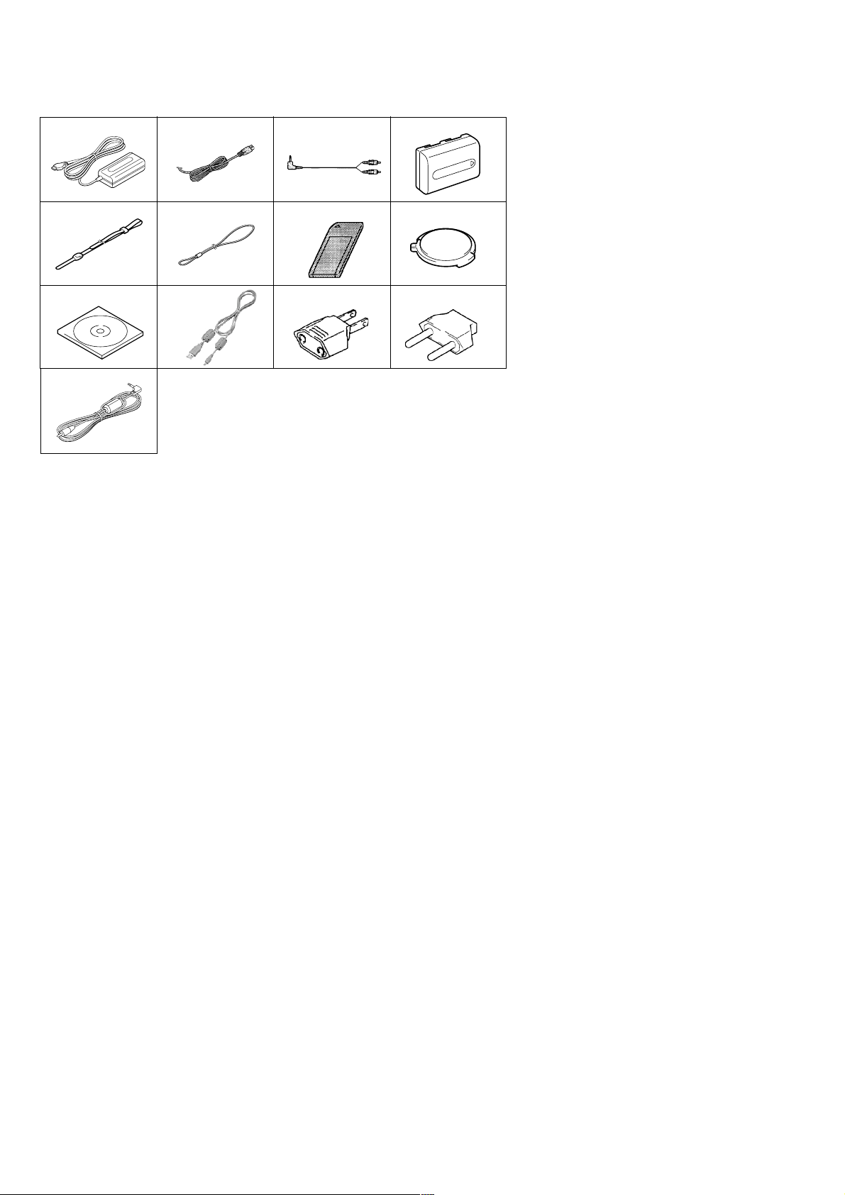
Supplied accessories
134
5678
90qaqs
qd
2
1 AC-L10 AC power adaptor
2 Power cord (1)
3 A/V connecting cable (DSC-S50) (1)
4 NP-FM50 Battery pack (1)
5 Wrist strap (1)
6 Lens cap strap (1)
7 Memory Stick (4MB) (1)
8 Lens cap (1)
9 Bundle soft (2000) (1)
(Compact Disk)
0 USB cable (1)
qa 2-pin conversion adaptor (1)
E model
qs 2-pin conversion adaptor (1)
Tourist model
qd VIDEO connecting cable (DSC-S30) (1)
SAFETY-RELATED COMPONENT WARNING!!
COMPONENTS IDENTIFIED BY MARK 0 OR DOTTED
LINE WITH MARK 0 ON THE SCHEMATIC DIAGRAMS
AND IN THE PARTS LIST ARE CRITICAL TO SAFE
OPERATION. REPLACE THESE COMPONENTS WITH
SONY PARTS WHOSE PART NUMBERS APPEAR AS
SHOWN IN THIS MANUAL OR IN SUPPLEMENTS PUBLISHED BY SONY.
SAFETY CHECK-OUT
After correcting the original service problem, perform the following
safety checks before releasing the set to the customer.
1. Check the area of your repair for unsoldered or poorly-soldered connections. Check the entire board surface for solder
splashes and bridges.
2. Check the interboard wiring to ensure that no wires are
“pinched” or contact high-wattage resistors.
3. Look for unauthorized replacement parts, particularly transistors, that were installed during a previous repair. Point them
out to the customer and recommend their replacement.
ATTENTION AU COMPOSANT AYANT RAPPORT
À LA SÉCURITÉ!
LES COMPOSANTS IDENTIFIÉS P AR UNE MARQUE 0
SUR LES DIAGRAMMES SCHÉMATIQUES ET LA LISTE
DES PIÈCES SONT CRITIQUES POUR LA SÉCURITÉ
DE FONCTIONNEMENT. NE REMPLACER CES COMPOSANTS QUE PAR DES PIÈCES SONY DONT LES
NUMÉROS SONT DONNÉS DANS CE MANUEL OU
DANS LES SUPPLÉMENTS PUBLIÉS PAR SONY.
4. Look for parts which, though functioning, show obvious signs
of deterioration. Point them out to the customer and recommend their replacement.
5. Check the B+ voltage to see it is at the values specified.
6. Flexible Circuit Board Repairing
• Keep the temperature of the soldering iron around 270 ˚C
during repairing.
• Do not touch the soldering iron on the same conductor of
the circuit board (within 3 times).
• Be careful not to apply force on the conductor when sol-
dering or unsoldering.
– 2 –
Page 3

TABLE OF CONTENTS
Section Title Page Section Title Page
SERVICE NOTE................................................................... 5
1. GENERAL
Identifying the Parts................................................................. 1-1
Preparing the Power Supply.................................................... 1-2
Setting the Date and Time....................................................... 1-3
Inserting the “Memory Stick” ................................................... 1-4
Recording Still Images ............................................................ 1-4
Recording Moving Images (DSC-C50 only)............................ 1-5
Playing Back Still Images ........................................................ 1-5
Playing Back Moving Images .................................................. 1-5
Viewing Images Using a Personal Computer ......................... 1-6
Image File Storage Destinations and Image Files.................. 1-7
Before Performing Advanced Operations ............................... 1-7
Various Recording ................................................................... 1-9
Various Playback ..................................................................... 1-11
Editing ..................................................................................... 1-12
Precautions.............................................................................. 1-13
On “Memory Sticks” ................................................................. 1-14
Using Your Camera Abroad ..................................................... 1-14
Troubleshooting ....................................................................... 1-14
Warning and Notice Messages ............................................... 1-15
Self-diagnosis Display ............................................................. 1-15
LCD Screen Indicators ............................................................ 1-16
2. DISASSEMBLY
• Attachment of CPC-9 Jig ...................................................... 2-1
2-1. PD-127 Board and Indicator Module ............................ 2-2
• Service Position (LCD Panel and PD-127 Board)................ 2-2
2-2. Front Cabinet Block Assembly ...................................... 2-3
2-3. Battery Lid Assembly and Control Switch Block .......... 2-3
2-4. Flash Unit and Upper Cabinet Block............................. 2-4
2-5. MS-50 Board and BT Holder Assembly ........................ 2-4
2-6. Lens Block Assembly .................................................... 2-5
2-7. SY-58 Board, DD-141 Board
and JK-194 Board ......................................................... 2-5
2-8. Control Switch Block and SW-339 Board ..................... 2-6
• Overall Check Service Position ............................................ 2-6
2-9. Hinge Assembly and KJ-11 Board ................................ 2-7
2-10. Circuit Boards Location ................................................. 2-8
2-11. Flexible Boards Location ............................................... 2-8
3. BLOCK DIAGRAMS
3-1. Overall Block Diagram................................................... 3-1
3-8. Power Block Diagram 1 ................................................. 3-15
3-9. Power Block Diagram 2 ................................................. 3-17
4. PRINTED WIRING BOARDS AND
SCHEMATIC DIAGRAMS
4-1. Frame Schematic Diagram (1/2) ................................... 4-3
Frame Schematic Diagram (2/2)................................... 4-5
4-2. Pr inted Wiring Boards and Schematic Diagram ........... 4-7
• CD-262 (CCD Imager)
Printed Wiring Board ................................................ 4-7
• CD-262 (CCD Imager)
Schematic Diagram .................................................. 4-8
• MS-50 (FU, Memory Stick)
Printed Wiring Board ................................................ 4-9
• MS-50 (FU, Memory Stick)
Schematic Diagram .................................................. 4-10
• PD-127 (TG, LCD)
Printed Wiring Board ................................................ 4-31
• PD-127 (LCD Drive)
Schematic Diagram .................................................. 4-33
• PD-127 (Timing Generator)
Schematic Diagram .................................................. 4-35
• JK-194 (USB, A/V out), KJ-11 (Panel Reverse),
SW-339 (Switch) Printed Wiring Boards.................. 4-37
• JK-194 (USB, A/V out), KJ-11 (Panel Reverse),
SW-339 (Switch) Schematic Diagrams .................... 4-39
• DD-141 (DC/DC Converter, Video, USB)
Printed Wiring Board ................................................ 4-41
• DD-141 (DC/DC Converter)
Schematic Diagram .................................................. 4-43
• DD-141 (Video)
Schematic Diagram .................................................. 4-45
• DD-141 (USB)
Schematic Diagram .................................................. 4-47
4-3. Waveforms..................................................................... 4-49
4-4. Parts Location ............................................................... 4-51
5. ADJUSTMENTS
Before Starting Adjustment ..................................................... 5-1
1-1. Adjusting Items when Replacing
Main Parts and Boards.................................................. 5-2
5-1. Camera Section Adjustment ......................................... 5-3
1-1. Preparations Before Adjustment................................... 5-3
1-1-1. List of Service Tools ................................................. 5-3
1-1-2. Preparations ............................................................. 5-4
1-1-3. Discharging of the Flashlight Power Supply ............ 5-4
1-1-4. Precautions .............................................................. 5-6
1. Setting the Switch .................................................... 5-6
2. Order of Adjustments ............................................... 5-6
3. Subjects.................................................................... 5-6
4. Preparing the Flash Adjustment Box ....................... 5-7
1-2. Initialization of B, D, E, F, 7 Page Data ......................... 5-8
1-2-1. Initialization of D Page Data .................................... 5-8
1. Initializing the D Page Data ...................................... 5-8
2. Modification of D Page Data .................................... 5-8
3. D Page Table ............................................................ 5-8
1-2-2. Initialization of B, E, F, 7 Page Data ........................ 5-9
1. Initializing the B, E, F, 7 Page Data ......................... 5-9
2. Modification of B, E, F, 7 Page Data ........................ 5-9
3. B Page Table ............................................................ 5-9
4. E Page Table ............................................................ 5-9
5. F Page Table............................................................. 5-10
6. 7 Page Ta ble ............................................................. 5-11
1-3. Video System Adjustments ........................................... 5-12
1. Video Sync Level Adjustment ....................................... 5-12
2. Video Burst Level Adjustment....................................... 5-12
1-4. Camera System Adjustment ......................................... 5-13
1. HALL Adjustment .......................................................... 5-13
2. Flange Back Adjustment
(Using the minipattern box)........................................... 5-14
3. Flange Back Check ....................................................... 5-15
4. F No. Standard Data Input ............................................ 5-16
5. Mechanical Shutter Adjustment .................................... 5-16
6. Picture Frame Setting.................................................... 5-17
7. Light Level Adjustment.................................................. 5-18
8. Mixed Color Cancel Adjustment.................................... 5-18
9. Auto White Balance Standard Data Input..................... 5-19
10. Auto White Balance Adjustment ................................... 5-19
11. Color Reproduction Adjustment.................................... 5-20
12. Color Reproduction Check............................................ 5-21
13. White Balance Check.................................................... 5-22
14. Strobe White Balance Adjustment ................................ 5-23
15. Strobe Light Level and White Balance Check .............. 5-23
16. CCD Black Defect Compensation ................................. 5-24
17. CCD White Defect Compensation ................................ 5-24
1-5. LCD System Adjustments ............................................. 5-25
1. LCD Initial Data Input .................................................... 5-26
2. VCO Adjustment (PD-127 Board)................................. 5-26
3. D Range Adjustment (PD-127 Board) .......................... 5-27
4. Bright Adjustment (PD-127 Board) ............................... 5-27
5. Contrast Adjustment (PD-127 Board)........................... 5-28
6. Color Adjustment (PD-127 Board) ................................ 5-28
7. V-COM Level Adjustment (PD-127 Board) ................... 5-29
8. V-COM Adjustment (PD-127 Board)............................. 5-29
9. White Balance Adjustment (PD-127 Board) ................. 5-30
– 3 –
Page 4

Section Title Page
1-6. System Control System Adjustments ........................... 5-31
1. Battery Down Adjustment ............................................. 5-31
5-2. Service Mode ................................................................ 5-32
2-1. Adjusting Remote Commander ..................................... 5-32
1. Used Adjusting Remote Commander ........................... 5-32
2. Precautions upon Using
the Adjusting Remote Commander............................... 5-32
2-2. Data Process ................................................................. 5-33
2-3. Service Mode ................................................................ 5-34
1. Setting the Test Mode.................................................... 5-34
2. Bit V alue Discrimination ................................................ 5-34
3. Switch Check (1) ........................................................... 5-34
4. Switch Check (2) ........................................................... 5-35
5. LED Check .................................................................... 5-35
6. LCD Check .................................................................... 5-35
6. REPAIR PARTS LIST
6-1. Exploded Views ............................................................. 6-1
6-1-1. Front Panel Section.................................................. 6-1
6-1-2. Main Section............................................................. 6-2
6-1-3. Rear Cabinet Section ............................................... 6-3
6-1-4. Lens Block Assembly ............................................... 6-4
6-2. Electr ical Parts List ....................................................... 6-5
* The color reproduction frame is shown on page 117.
– 4 –
Page 5
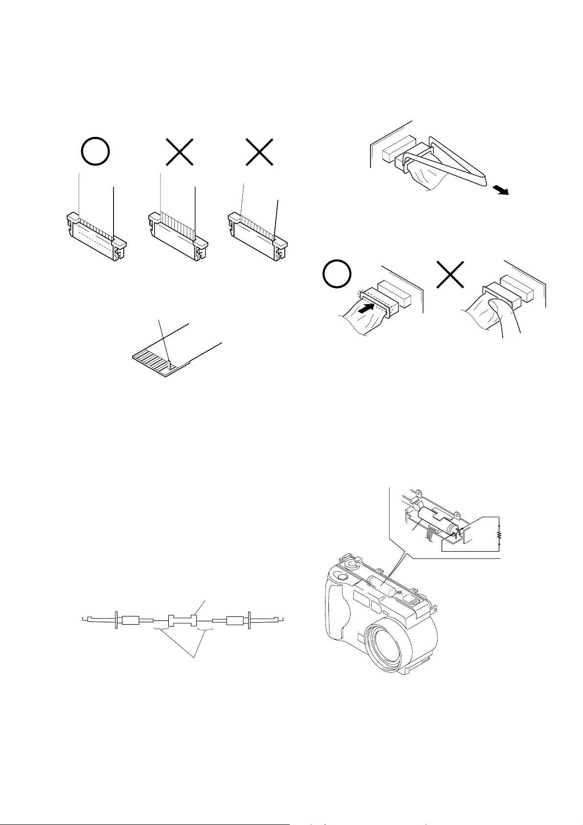
SERVICE NOTE
When installing a connector, don’t press down at wire of connector.
Be in danger of the snapping of a wire.
• NOTE FOR REPAIR
Make sure that the flat cable and flexible board are not cracked of
bent at the terminal.
Do not insert the cable insufficiently nor crookedly.
Cut and remove the part of gilt
which comes off at the point.
(Take care that there are some
pieces of gilt left inside)
When remove a connector, don’t pull at wire of connector.
Be in danger of the snapping of a wire.
[Discharging of the FLASH unit’s charging capacitor]
The charging capacitor of the FLASH unit is charged up to the
maximum 300 V potential.
There is a danger of electric shock by this high voltage when the
battery is handled by hand. The electric shock is caused by the
charged voltage which is kept without discharging when the main
power of the MVC-FD71 is simply turned off. Therefore, the remaining voltage must be discharged as described below.
Preparing the Short Jig
T o preparing the short jig. a small clip is attached to each end of a
resistor of 1 kΩ /1 W (1-215-869-11).
Wrap insulating tape fully around the leads of the resistor to prevent electrical shock.
1 kΩ/1 W
Wrap insulating tape.
Discharging the Capacitor
Short-circuit between the positive and the negative terminals of
charged capacitor with the short jig about 10 seconds.
R: 1 kΩ/1 W
Capacitor
(Part code:
1-215-869-11)
– 5 –
Page 6

[Description on Self-diagnosis Display]
Self-diagnosis display
• C: ss
You can reverse the camera
malfunction yourself. (However,
contact your Sony dealer or local
authorized Sony service facility
when you cannot recover from the
camera malfunction.)
• E: ss
Contact your Sony dealer or local
authorized Sony service facility.
Display Code
C:32:ss
C:13:ss
E:61:ss
E:91:ss
Turn the power off and on again.
Format the “Memory stick”.
Insert a new “Memory Stick”.
Checking of lens drive circuit.
*1
Checking of flash unit or replacement
of flash unit.
Countermeasure
Cause
Trouble with hardware.
Unformatted memory stick is inserted.
Memory stick is broken.
When failed in the focus and zoom
initialization.
Abnormality when flash is being
charged.
Note: The error code is cleared if the battery is removed, except defective flash, unit.
*1: The error display is given in two ways.
*2: When the flash charging failed, Page : D, Address: 67. Data: 04 are written.
After repair, be sure to write Page: D, address: 67. Data: 00.
Caution Display During Error
SYSTEM ERROR
FORMAT ERROR
MEMORY STICK ERROR
—
*2
– 6 –
Page 7
DSC-S30/S50
3
Note:
This equipment has been tested and found to
comply with the limits for a Class B digital
device, pursuant to Part 15 of the FCC
Rules. These limits are designed to provide
reasonable protection against harmful
interference in a residential installation. This
equipment generates, uses, and can radiate
radio frequency energy and, if not installed
and used in accordance with the
instructions, may cause harmful interference
to radio communications. However, there is
no guarantee that interference will not occur
in a particular installation. If this equipment
does cause harmful interference to radio or
television reception, which can be
determined by turning the equipment off and
on, the user is encouraged to try to correct
the interference by one or more of the
following measures:
— Reorient or relocate the receiving
antenna.
— Increase the separation between the
equipment and receiver.
— Connect the equipment into an outlet
on a circuit different from that to which
the receiver is connected.
— Consult the dealer or an experienced
radio/TV technician for help.
The shielded interface cable recommended
in this manual must be used with this
equipment in order to comply with the limits
for a digital device pursuant to Subpart B of
Part 15 of FCC Rules.
DISPOSAL OF LITHIUM ION
BATTERY.
LITHIUM ION BATTERY.
DISPOSE OF PROPERLY.
You can return your unwanted lithium ion
batteries to your nearest Sony Service
Center or Factory Service Center.
Note:
In some areas the disposal of lithium ion
batteries in household or business trash may
be prohibited.
For the Sony Service Center nearest you call
1-800-222-SONY (United States only)
For the Sony Factory Service Center nearest
you call 416-499-SONY (Canada only)
Caution:
Do not handle damaged or leaking lithium
ion battery.
CAUTION
TO PREVENT ELECTRIC SHOCK, DO
NOT USE THIS POLARIZED AC PLUG
WITH AN EXTENSION CORD,
RECEPTACLE OR OTHER OUTLET
UNLESS THE BLADES CAN BE FULLY
INSERTED TO PREVENT BLADE
EXPOSURE.
A moulded plug complying with BS 1363 is
fitted to this equipment for your safety and
convenience.
Should the fuse in the plug supplied need to
be replaced, a 5 AMP fuse approved by
ASTA or BSI to BS 1362, (i.e. marked with
or mark) must be used.
If the plug supplied with this equipment has
a detachable fuse cover, be sure to attach the
fuse cover after you change the fuse. Never
use the plug without the fuse cover. If you
should lose the fuse cover, please contact
your nearest Sony service station.
Directive:EMC Directive 89/336/EEC.92/
31/EEC
This equipment complies with the EMC
regulations when used under the following
circumstances:
• Residential area
• Business district
• Light-industry district
(This equipment complies with the EMC
standard regulations EN55022 Class B.)
For the Customers in Canada
NOTICE FOR THE
CUSTOMERS IN THE UNITED
KINGDOM
For the Customers in
Germany
WARNING
To prevent fire or shock hazar d, do
not expose the unit to rain or
moisture.
For the Customers in the
U.S.A.
This symbol is intended to
alert the user to the presence
of uninsulated “dangerous
voltage” within the
product’s enclosure that
may be of sufficient
magnitude to constitute a
risk of electric shock to
persons.
This symbol is intended to
alert the user to the presence
of important operating and
maintenance (servicing)
instructions in the literature
accompanying the
Never expose the battery pack to
temperature above 140˚F (60˚C), such as in
a car parked in the sun or under direct
sunlight.
If you have any questions about this
product, you may call:
or write to:
appliance.
Sony Customer Information Center
1-800-222-SONY (7669)
Sony Customer Information Center
1 Sony Drive, Mail Drop #T1-11, Park
Ridge, NJ 07656
CAUTION
You are cautioned that any changes or
modifications not expressly approved in this
manual could void your authority to operate
this equipment.
Declaration of Conformity
Trade Name: SONY
Model No.: DSC-S30
Responsible Party:Sony Electronics Inc.
Address: 1 Sony Drive, Park
Telephone No.: 201-930-6972
This device complies with Part 15 of the
FCC Rules. Operation is subject to the
following two conditions: (1) This
device may not cause harmful
interference, and (2) this device must
accept any interference received,
including interference that may cause
undesired operation.
Declaration of Conformity
Trade Name: SONY
Model No.: DSC-S50
Responsible Party:Sony Electronics Inc.
Address: 1 Sony Drive, Park
Telephone No.: 201-930-6972
This device complies with P
FCC Rules. Operation is subject to the
following two conditions: (1) This
device may not cause harmful
interference, and (2) this device must
accept any interference received,
including interference that may cause
undesired operation.
Ridge, NJ 07656
USA
Ridge, NJ 07656
USA
art 15 of the
1. GENERAL
This section is extracted from DSC-S30/S50
instruction manual.
2
Attention
The electromagnetic fields at the specific
frequencies may influence the picture and
sound of this camera.
“Memory Stick”
For the Customers in CANADA
This Class B digital apparatus complies with
Canadian ICES-003.
For the Customers in the
U.S.A.
This device complies with Part 15 of the
FCC Rules. Operation is subject to the
following two conditions: (1) This device
may not cause harmful interference, and
(2) this device must accept any interference
received, including interference that may
cause undesired operation.
Be sure to read the following
before using your camera
• This Owner's Manual is for the two
models of the DSC-S30 and the
DSC-S50. Check to make sure which
model you have purchased before
you use your camera.
• The illustrations in this manual
show the DSC-S50.
Trial recording
Before you record one-time events, you may
want to make a trial recording to make sure
that the camera is working correctly.
No compensation for contents of
the recording
Contents of the recording cannot be
compensated for if recording or playback is
not possible due to a malfunction of your
camera, etc.
4
Notes on image data compatibility
• This camera conforms with the Design
Rules for Camera File Systems universal
standard established by the JEIDA (Japan
Electronic Industries Development
N50
Association). You cannot play back on
your camera still images recorded on other
equipment (DCR-TRV890/TRV900/
TRV900E, DSC-D700, DSC-D770) that
does not conform with this universal
standard. (These models are not sold in
some areas.)
• Playback of images recorded with your
camera on other equipment and playback
of images recorded or edited with other
equipment on your camera are not
guaranteed.
Precaution on copyright
Television programs, films, video tapes, and
other materials may be copyrighted.
Unauthorized recording of such materials
may be contrary to the provision of the
copyright laws.
Do not shake or strike the camera
In addition to malfunctions and inability to
record images, this may render the
“Memory Stick” unusable or image data
breakdown, damage or loss may occur.
LCD screen and lens
• The LCD screen is manufactured using
high-precision technology. However, there
may be some tiny black points and/or
bright points (red, blue or green in color)
that constantly appear on the LCD screen.
These points are normal in the
manufacturing process and do not affect
the recording in any way. Over 99.99% of
the pixels are operational for effective use.
• Be careful when placing the camera near a
window or outdoors. Exposing the LCD
screen or the lens to direct sunlight for
long periods may cause malfunctions.
Do not get the camera wet
When taking pictures outdoors in the rain or
under similar conditions, be careful not to
get the camera wet. If moisture
condensation occurs, refer to page 54 and
follow the instructions on how to remove it
before using the camera.
Back up recommendation
To avoid the potential risk of data loss,
always copy (back up) data to a disk.
Getting started
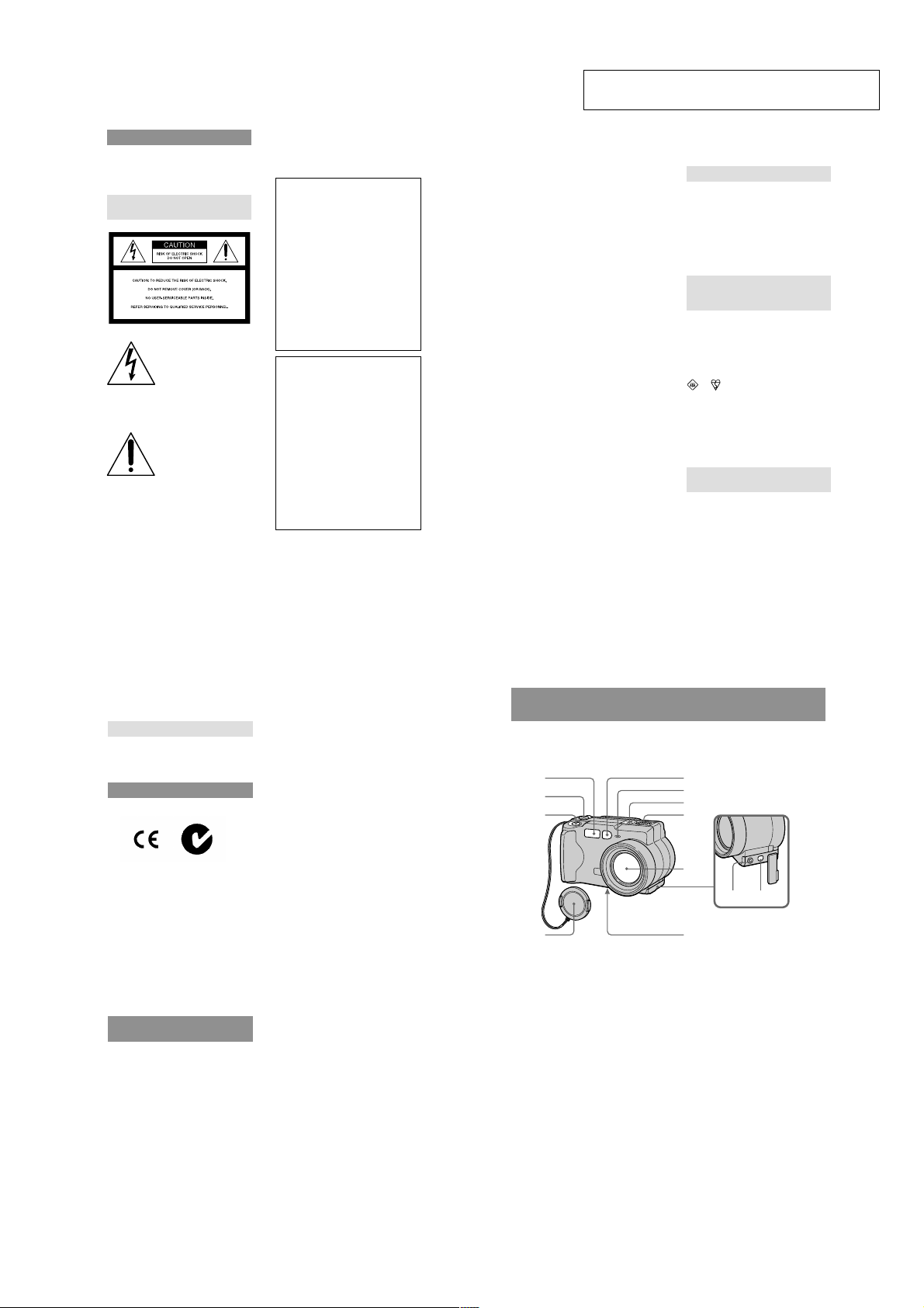
Identifying the parts
See the pages in parentheses for details of operation.
1
2
3
4
A Flash (19)
B MODE selector (29)
C Shutter button (16) (20)
D Lens cap
E Photocell window for flash
Do not block while recording.
F Self-timer/recording lamp
G Built-in microphone (DSC-S50
only)
Do not touch while recording.
H Speaker (DSC-S50 only)
6
1-1
5
6
7
8
9
0qsqa
I Lens
J A/V OUT jack (DSC-S50 only)
(48)
Audio output is monaural.
VIDEO OUT jack (DSC-S30
only) (48)
K USB jack (25) (26)
L Tripod receptacle (bottom
surface)
Use a tripod with a screw length of
less than 9/32 inch (6.5 mm). You
will be unable to firmly secure the
camera to tripods having longer
screws, and may damage the
camera.
Page 8
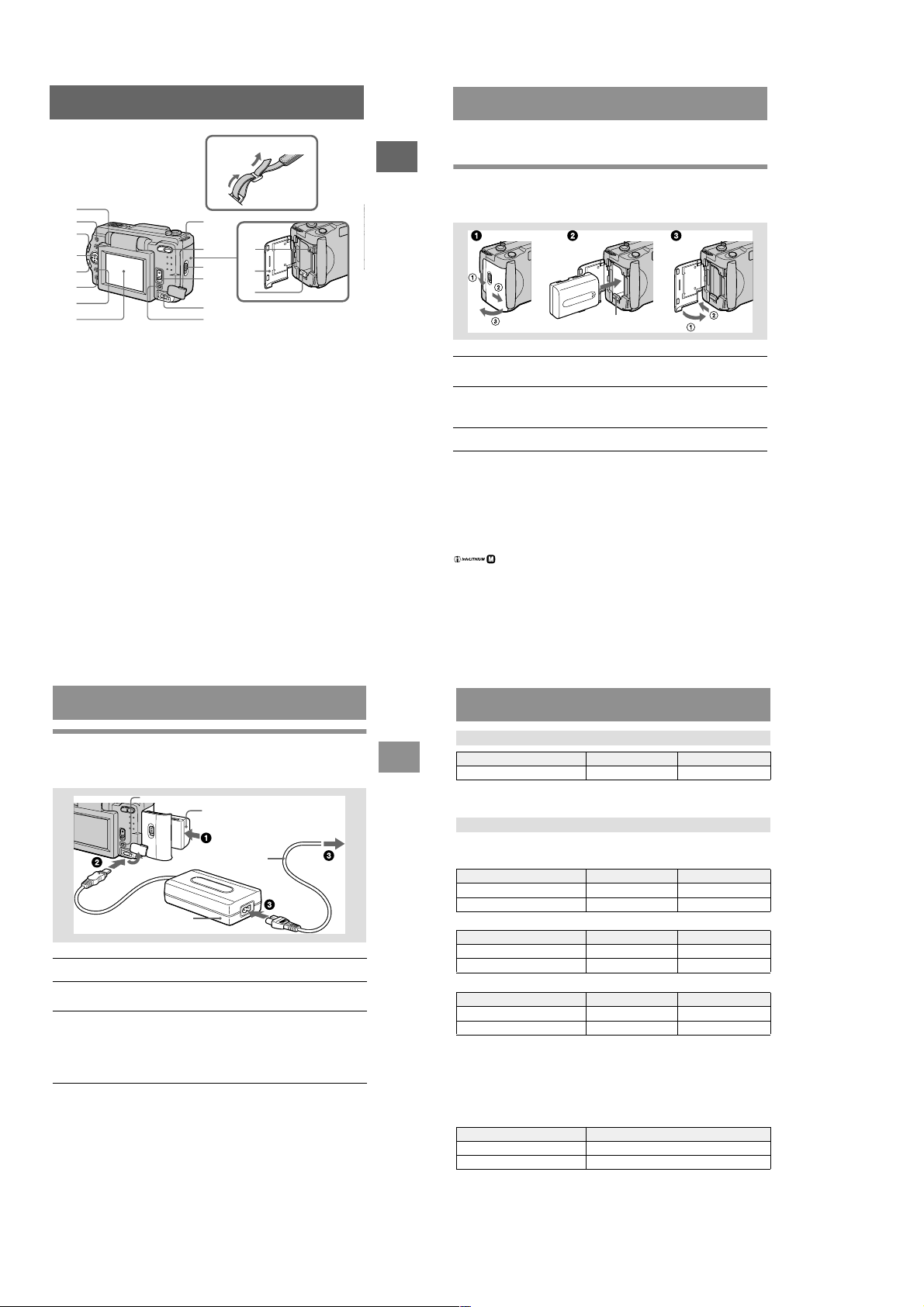
Attaching the strap
Preparing the power supply
1
2
3
4
5
6
7
8
A Flash button
B FOCUS button (41)
C LCD BACKLIGHT BRIGHT/
NORMAL switch
Usually set to NORMAL. When
you use the camera outdoors or in
other bright places, setting this to
BRIGHT makes the LCD screen
bright and easy to see, but also
uses up the battery faster.
D Control button
E PROGRAM AE +/– button
VOLUME +/– button
F PROGRAM AE button (42)
9
0
qa
qf
qs
qg
qd
qh
qj
G DISPLAY button
H LCD screen
I Hook for lens cap/strap
J Zoom button
K Access lamp (15)
L Battery/“Memory Stick” cover
M Battery eject lever (8)
N OPEN switch
O POWER switch
P DC IN jack (9) (12)
Q POWER lamp/BATT CHARGE
lamp (9) (13)
Getting started
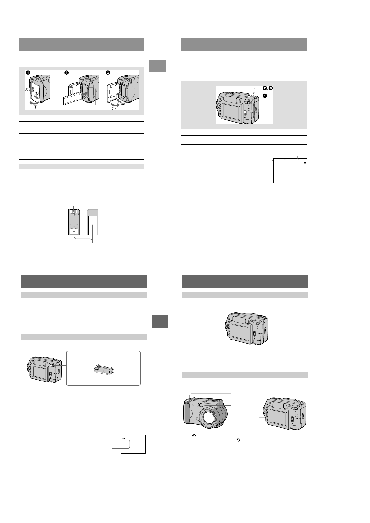
Installing the battery pack
Your camera operates only with the “InfoLITHIUM” NP-FM50 battery pack* (M
series). You cannot use any other battery pack.
Battery eject lever
Open the battery/“Memory Stick” cover.
1
Open the cover while sliding the OPEN switch in the direction of the arrow.
Install the battery pack.
2
Insert the battery pack with the B mark facing tow ard the battery compartment
as illustrated.
Close the battery/“Memory Stick” cover.
3
To remove the battery pack
Open the battery/“Memory Stick” cover. Slide the battery eject lever
downward, and remove the battery pack.
Be careful not to drop the battery pack when removing it.
* What is “InfoLITHIUM”?
“InfoLITHIUM” is a lithium ion battery pack which can exchange information such as battery
consumption with compatible video equipment. This unit is compatible with the
“InfoLITHIUM” battery pack (M series). “InfoLITHIUM” M series battery packs have the
mark. “InfoLITHIUM” is a trademark of Sony Corporation.
Charging the battery pack
You cannot charge the battery pack while your camera is turned on. Be sure to turn
off your camera before charging.
Insert the battery pack into your camera.
1
Open the DC IN jack cover and connect the DC connecting cable to
2
the DC IN jack of your camera with the v mark facing up.
Connect the power cord (mains lead) to the AC power adaptor and
3
then to a wall outlet (mains).
The BATT CHARGE lamp lights orange when charging begins. When the
BATT CHARGE lamp goes off, normal charge is completed. For full
charge, which allows you to use the battery longer than usual, leave the
battery pack inserted for about one hour after normal charge is completed.
Battery remaining indicator
The LCD screen on the camera shows the remaining time for which you can still
record or play back images.
This indication may not be entirely accurate depending on the conditions of use and
the operating environment.
Auto power-off function
If you do not operate the camera for about three minutes during recording, the
camera turns off automatically to prevent wearing down the battery. To use the
camera again, slide down the POWER switch to turn on the camera again.
BATT CHARGE lamp
DC IN jack cover
AC-L10
AC power adaptor
Battery pack (M series)
To the wall outlet (mains)
Power cord
(mains lead)
7
Getting started
8
Charging time
Battery pack Full charge (min.) Normal charge (min.)
NP-FM50 (supplied) 150 90
Approximate time to charge a completely discharged battery pack using the A
AC power adaptor.
Battery life and number of images that can be recorded/played back
STILL mode recording*
DSC-S50
LCD BACKLIGHT Battery life (min.) Number of images
BRIGHT 140 (130) 2300 (2100)
NORMAL 150 (140) 2500 (2300)
DSC-S30
LCD BACKLIGHT Battery life (min.) Number of images
BRIGHT 140 (130) 2800 (2600)
NORMAL 150 (140) 3000 (2800)
STILL mode playback** (DSC-S50/S30)
LCD BACKLIGHT Battery life (min.) Number of images
BRIGHT 170 (160) 3400 (3200)
NORMAL 220 (210) 4400 (4200)
Approximate battery life and number of images that can be recorded/played back
with a fully charged battery pack at a temperature of 77˚F (25˚C), 640×480 image
size and in NORMAL recording mode. Numbers in parentheses indicate the time
when you use a normally charged battery pack.
∗ Recording at about 5-second intervals
∗∗Playing back single images in order at about 3-second intervals
MOVIE mode recording (DSC-S50 only)
LCD BACKLIGHT Battery life (min.)
BRIGHT 140 (130)
NORMAL 150 (140)
Approximate time that can be recorded with a fully charged battery pack at a
temperature of 77˚F (25˚C) and 160×112 image size. Numbers in parentheses
indicate the time when you use a normally charged battery pack.
C-L10
9
10
1-2
Page 9
Notes
• The battery life and number of images will be decreased if you use your camera at low
temperatures, use the flash, repeatedly turn the power on/off or use the zoom.
• The capacity of the “Memory Stick” is limited. The above figures are a guide when you
continuously record/play back while replacing the “Memory Stick.”
• If sufficient battery remaining time is indicated but the power runs out soon, fully charge the
battery so that the correct battery remaining time appears.
• Do not short the DC plug of the AC power adaptor with a metallic object, as this may cause
malfunction.
• Do not expose the battery pack to water.
Getting started
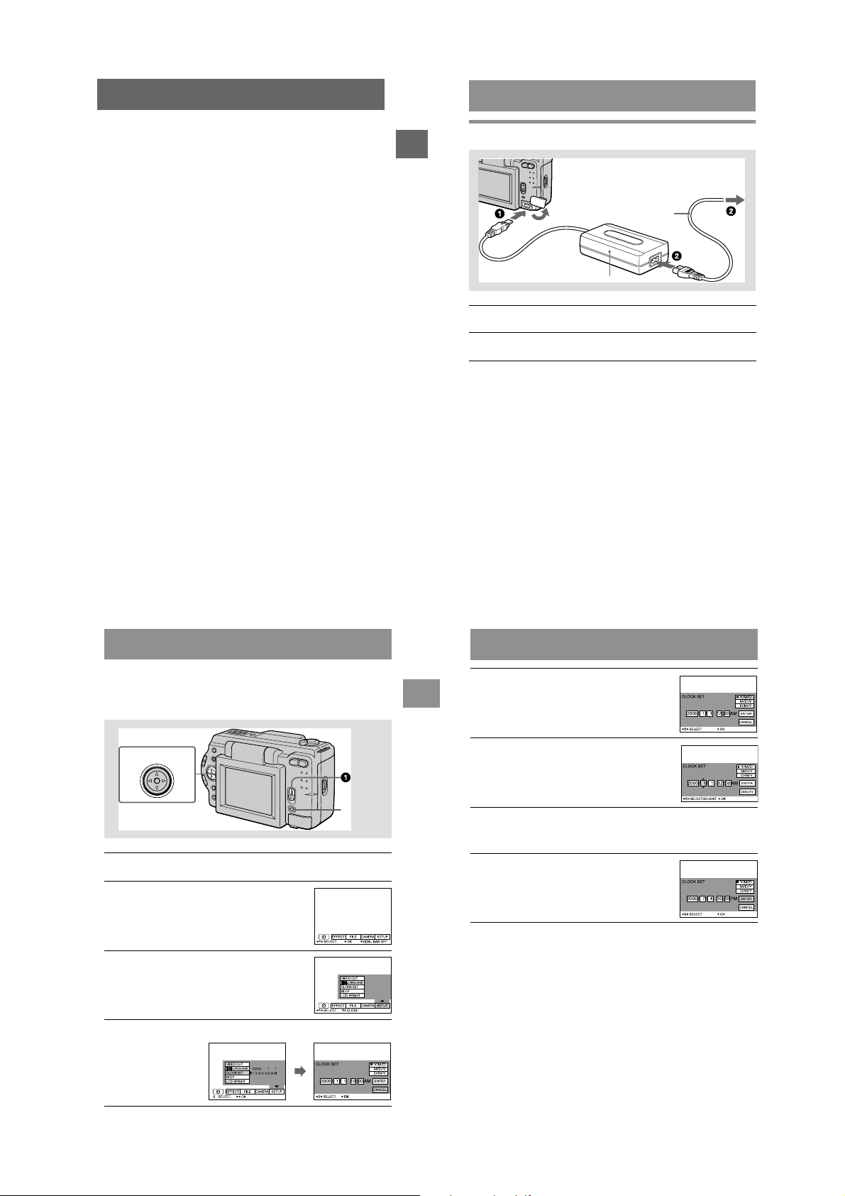
Using the AC power adaptor
To the wall outlet (mains)
DC IN jack cover
AC-L10 AC power adaptor
Open the DC IN jack cover and connect the DC connecting cable to
1
the DC IN jack of your camera with the v mark facing up.
Connect the power cord (mains lead) to the AC power adaptor and
2
then to a wall outlet (mains).
Using a car battery
Use Sony DC adaptor/charger.
Power cord
(mains lead)
Setting the date and time
When you first use your camera, set the date and time. If these are not set, the
CLOCK SET screen appears whenever you turn on your camera for recording.
Control button
POWER
lamp
Slide down the POWER switch to turn on the power.
1
The POWER lamp lights up.
Press v on the control button.
2
The menu bar appears on the LCD screen.
Select [SETUP] with B on the control button,
3
then press the center z.
11
Getting started
12
Select the desired date display format with
5
v/V on the control button, then press the
center z.
Select from Y/M/D (year/month/day), M/D/Y
(month/day/year) or D/M/Y (day/month/year).
Select the year, month, day, hour or minute
6
item you want to set with b/B on the control
button.
The item to be set is indicated with v/V.
Set the numeric value with v/V on the control button, then press
7
the center z to enter it.
After entering the number, v/V moves to the next item.
If you selected [D/M/Y] in step 5, set the time on a 24-hour cycle.
Select [ENTER] with B on the control
8
button, then press the center z at the
desired moment to begin clock movement.
The date and time are entered.
To cancel the date and time setting
Select [CANCEL] with v/V/b/B on the control button, then press the center z.
Select [CLOCK SET] with v/V on the control button, then press the
4
center z.
13
14
1-3
Page 10
Inserting the “Memory Stick”
Getting started
Basic operations
B Recording
Recording still images
Still images are recorded in JPEG format.
To record still images, slide the POWER switch down to turn on the power and insert
a “Memory Stick.”
Access lamp
Open the battery/“Memory Stick” cover.
1
Open the cover while sliding the OPEN switch in the direction of the arrow.
Insert the “Memory Stick.”
2
Insert the “Memory Stick” with the B mark facing toward the battery
compartment as illustrated until it clicks.
Close the battery/“Memory Stick” cover.
3
Removing the “Memory Stick”
Open the battery/“Memory Stick” cover, then press the “Memory Stick” once lightly.
Notes
• Insert the “Memory Stick” firmly until it clicks, otherwise a message such as “MEMORY
STICK ERROR” will be displayed.
• Never remove the “Memory Stick” or turn off the power while the access lamp is lit up.
• You cannot record or edit images on a “Memory Stick” if the erasure prev
the LOCK position.
Erasure prevention switch
ention switch is set to
Connector
LOCK
Label space
15
POWER switch
Set the MODE selector to STILL.
1
Press and hold the shutter button halfway
2
down and check the image.
While the AE lock indicator z (green) is flashing,
the image freezes momentarily, but is not yet
recorded. When the camera finishes the automatic
adjustments*, the AE lock indicator z lights up
and the camera is ready for recording.
To cancel the recording, release the shutter b
Press the shutter button fully down.
3
The shutter sounds and the image is recorded on the “Memory Stick.”
When “REC” disappears, you can record the next image.
∗ Exposure and focus are automatically adjusted.
The number of images you can record on a “Memory Stick”
See pages 37 to 40.
Note
While the image is being recorded on the “Memory Stick,” do not shake or strike the camera.
Also, do not turn the power off, or remove the battery pack or “Memory Stick.”
utton.
Remaining memory
capacity indicator
AE lock indicator
16
Checking the last recorded image (Quick Review)
You can check the last recorded image by clearing the menu bar from the screen
(page 31) and pressing b on the control button. To return to the normal recording
mode, press lightly on the shutter button or select [RETURN] with b/B on the
control button and then press the center z. You can also delete the image first by
selecting [DELETE] on the Quick Review screen with b/B on the control button and
pressing the center z, and then selecting [OK] with v/V on the control button and
pressing the center z.
Using the zoom feature
Zoom button
W side: for wide-angle (subject appears
farther away)
T side: for telephoto (subject appears
closer)
Minimum focal distance to the subject
W side: About 9 7/8 inches (25 cm) or more
T side: About 23 5/8 inches (60 cm) or more
To record even closer subjects, see page 41.
Digital zoom function
This camera has a digital zoom function.
Digital zoom enlarges the image by digital processing and it starts to function when
zoom exceeds 3×.
The T side of the bar shows the
digital zooming zone.
Using digital zoom
• The maximum zoom magnification is 6×.
• Digital zooming deteriorates the picture quality. When digital zoom is not
necessary, set [DIGITAL ZOOM] to [OFF] in the menu settings (page 34).
Note
Digital zoom does not work for moving images.
17
B Recording
LCD screen indicators during recording
Press DISPLAY to turn on/off the indicators on the LCD screen.
See page 64 for a detailed description of the indicated items.
DISPLAY
Notes
• You cannot turn off the self-timer indicators and some of the indicators used in advanced
operations.
• The indicators on the LCD screen are not recorded.
Using the self-timer
When you use the self-timer function, the subject is recorded about 10 seconds after
you press the shutter button.
Shutter button
Self-timer lamp
Control button
Select (self-timer) indicator on the LCD screen with v/V/b/B on the control
button, then press the center z. The (self-timer) indicator appears on the LCD
screen, and about 10 seconds after you press the shutter button, the subject is
recorded. The self-timer lamp flashes after you press the shutter button until the
shutter is released.
18
1-4
Page 11

Recording images with the flash
B (playback)/X
The initial setting is auto (no indicator). In this mode, the flash automatically strobes
when the surroundings become dark. When you change the flash mode, press the
(flash) repeatedly so that the flash mode indicator appears on the LCD screen.
(flash)
B
Recording
Recording moving images (DSC-S50 only)
Moving images with audio are recorded in MPEG format.
To record moving images, slide the POWER switch down to turn on the power and
insert a “Memory Stick.”
Each time you press the (flash), the indicator changes as follows.
(No indicator) t t t t (No indicator)
Auto red-eye reduction: The flash strobes before recording to reduce the
Forced flash: The flash strobes regardless of the surrounding
No flash: The flash does not strobe.
You can change the brightness of the flash (FLASH LEVEL) in the menu settings
(page 34).
Notes
• The recommended shooting distance using the built-in flash is 31/32 feet to 8 1/3 feet (0.3 m to
2.5 m).
• Attaching a conversion lens (not supplied) may block the light from the flash or cause the lens
shadow to appear.
• Auto red-eye reduction may not produce the desired red-eye reduction effects depending on
individual differences, the distance to the subject, if the subject does not see the pre-strobe, or
other conditions. In addition, red-eye reduction effects are also difficult to obtain if you set the
shutter to a slow speed in the PROGRAM AE shutter priority mode.
• The flash effect is not obtained easily when you use forced flash in a bright location.
red-eye phenomenon.
brightness.
B Playback
19
DISPLAY
Set the MODE selector to MOVIE.
1
Press the shutter button fully down.
2
“REC” appears on the LCD screen, and the image and sound are recorded on
the “Memory Stick.”
If you press the shutter button momentarily
The image and sound are recorded for five seconds. You can change the
recording time to 10 or 15 seconds with [REC TIME SET] in the menu settings
(page 33).
If you hold the shutter button down
The image and sound are recorded while the shutter button is held down for up
to 60 seconds. However, when [IMAGE SIZE] in the menu setting is set to
[320×240], the maximum recording time is 15 seconds (page 33).
Zooming or using the self-timer, etc.
See pages 17 and 18.
LCD screen indicators during recording
Press DISPLAY to turn on/off the indicators on the LCD screen.
These indicators are not recorded. See page 64 for a detailed description of the
indicators.
POWER switch
20
Playing back still images
DISPLAY
Set the MODE selector to PLAY.
1
The last recorded image (still or moving) appears on the LCD screen.
Press v on the control button to display the menu bar on the LCD
2
screen.
Select the desired still image with the
3
control button.
Press v/V/b/B on the control button to select "b/B"
on the LCD screen, then press b/B on the control
button.
"b: To display the preceding image.
B": To display the next image.
When the menu bar is not displayed
You can directly select and play back the image with b/B on the control button.
Notes
• You might not be able to correctly play back images recorded with this camera on other
equipment.
• You cannot play back on this camera images larger than the maximum image size that can be
recorded with this camera.
LCD screen indicators during still image playback
Press DISPLAY to turn on/off the indicators on the LCD screen.
See page 64 for a detailed description of the indicators.
POWER switch
21
Playing back moving images
VOLUME +/–
DISPLAY
B
Playback
Set the MODE selector to PLAY.
1
The last recorded image (still or moving) appears on the LCD screen.
Press v on the control button to display the menu bar on the LCD
2
screen.
Select the desired moving image with the
3
control button.
Moving images are displayed one-size smaller than
still images.
Press v/V/b/B on the control button to select "b/B"
on the LCD screen, then press b/B on the control
button.
"b: To display the preceding image.
B": To display the next image.
Select B (playback) on the LCD screen with
4
v/V/b/B on the control button, then press
the center z.
The moving image and sound* are played back.
During playback, B (playback) changes to X
(pause).
∗ You can play back sound in DSC-S50 only.
To pause playback
Select X (pause) on the LCD screen with v/V/b/B on the control button, then press
the center z.
22
POWER switch
Playback bar
1-5
Page 12
When the menu bar is not displayed
You can directly select the image with b/B on the control button, and play back the
image and sound (DSC-S50 only) by pressing the center z. When you press the
center z during playback, playback is paused.
Adjusting the volume (DSC-S50 only)
Press VOLUME +/– to adjust the volume.
LCD screen indicators during moving image playback
Press DISPLAY to turn on/off the indicators on the LCD screen.
See page 64 for a detailed description of the indicators.
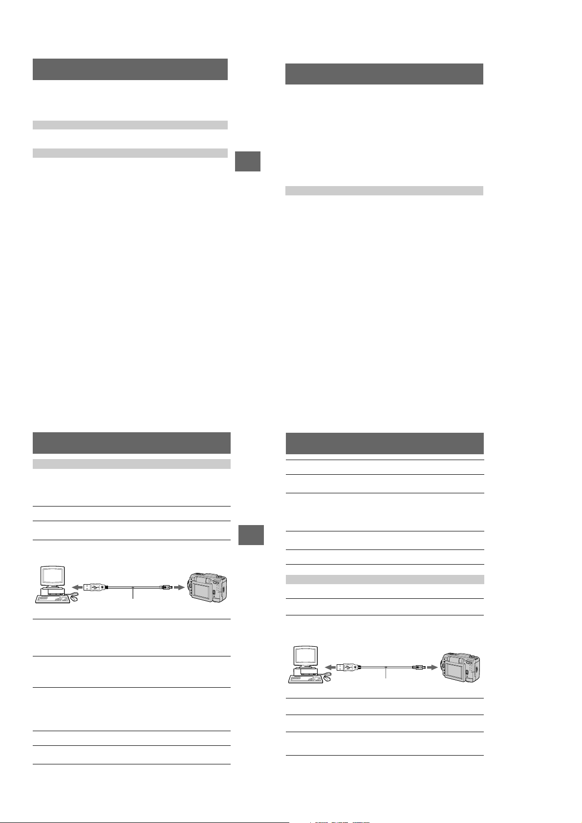
Viewing images using a personal computer
You can vie w data recorded with your camera on a personal computer and attach it to
e-mail. This section describes the method for installing the USB driver and viewing
images on a personal computer. Be sure to also see the operation manuals for your
personal computer and application software.
Note
Data recorded with your camera is stored in the following formats. Make sure that applications
that support these file formats are installed on your personal computer.
• Still images (other than TEXT and uncompressed modes): JPEG format
• Moving images/audio: MPEG format
B
Playback
• Uncompressed mode still images: TIFF format
• TEXT mode: GIF format
Recommended computer environment
Recommended Windows environment
OS: Microsoft Windows 98, Windows 98SE
Standard installation is required.
Operation is not assured in an environment upgraded from:
Windows
3.1, Windows 95 to Windows 98 or
Windows
CPU: MMX Pentium 200 MHz or faster
The USB connector must be provided as standard.
ActiveMovie Player (DirectShow) must be installed (to play back moving pictures).
Recommended Macintosh environment
Macintosh computer with the Mac OS 8.5.1/8.6/9.0 standard installation
However, note that the update to Mac OS 9.0 should be used for the following models.
The USB connector must be provided as standard.
QuickTime 3.2 or newer must be installed (to play back moving pictures).
Notes
• Operations are not guaranteed for either the Windows or Macintosh environment if you connect
two or more USB equipment to a single personal computer at the same time (except for the
USB keyboard and mouse which are provided as standard), or when using a hub.
• Depending on the type of USB equipment that is used simultaneously, some equipment may
not operate.
• Operations are not guaranteed for all the recommended computer environments mentioned
above.
98 to Windows 98SE.
• iMac with the Mac OS 8.6 standard installation and a slot loading type CD-ROM drive
• iBook or G4 with the Mac OS 8.6 standard installation
23
Installing the USB driver
Before connecting your camera to your personal computer, install the USB driver to
the computer. The USB driver is contained together with application software for
viewing images on a CD-ROM which is supplied with your camera.
For Windows 98 users
Turn on your personal computer and allow Windows 98 to load.
1
Insert the supplied CD-ROM in the CD-ROM drive of your personal
2
computer.
Connect the USB jack on your camera with the USB connector on
3
your personal computer using the supplied USB cable.
to the USB connector
Personal computer
Insert a “Memory Stick” into your camera, connect the AC power
4
adaptor and turn on your camera.
“PC MODE” appears on the LCD screen of your camera and the camera is set
to communication standby mode. Your personal computer recognizes the
camera, and the Windows 98 Add Hardware Wizard starts.
Follow the on-screen messages to specify the CD-ROM drive and
5
install the USB driver.
The Add Hardware Wizard starts twice because two different USB drivers are
installed. Be sure to allow the installation to complete without interrupting it.
Note
Be sure to insert a “Memory Stick” into your camera before installing the USB driver.
Otherwise, you will be unable to install the USB driver.
For Macintosh users
Turn on your personal computer and allow the Mac OS to load.
1
Insert the supplied CD-ROM in the CD-ROM drive of your personal
2
computer.
USB cable
to the USB jack
Push in until the
connector clicks
into place
24
Double-click the CD-ROM drive icon to open the window.
3
Double-click the icon of the hard disk containing the OS to open
4
the window.
Move the following two driver files from the window opened in step
5
3 to the “System Folder” icon in the window opened in step 4
(drag and drop).
• Sony USB Driver
• Sony USB Shim
When “Put these items into the Extensions folder?” appears, click
6
B
Playback
“OK.”
Restart your personal computer.
7
Viewing images
For Windows 98 users
Turn on the power of your personal computer and allow
1
Windows 98 to load.
Connect one end of the USB cable to the USB jack on the camera
2
and the other end to the USB connector on your personal
computer.
USB cable
to the USB jack
Push in until the
connector clicks
into place
to the USB connector
Personal computer
Insert a “Memory Stick” into your camera, and connect the AC
3
power adaptor to your camera and then to a wall outlet (mains).
Turn on the power of your camera.
4
“PC MODE” appears on the LCD screen of the camera.
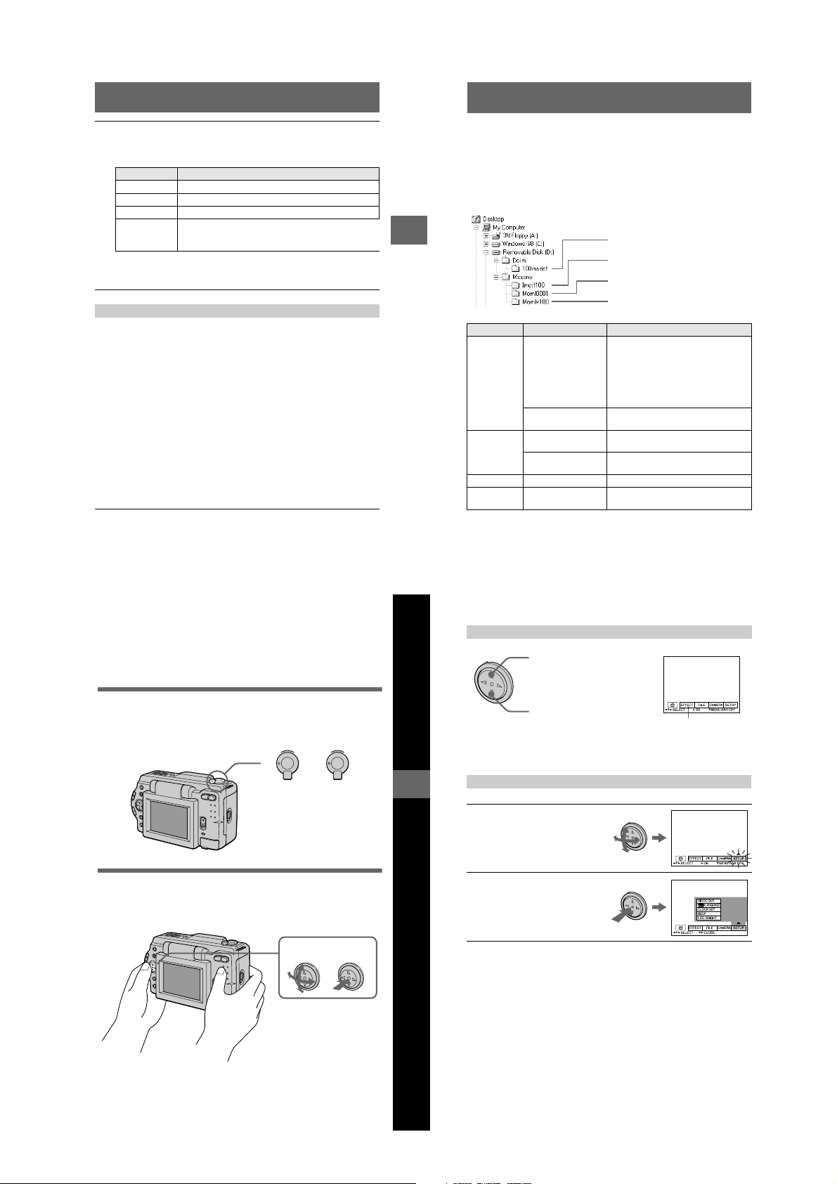
Open “My Computer” on Windows 98 and double click the newly
5
recognized drive. (Example: “Removable Disk (D:)”)
The folders inside the “Memory Stick” are displayed.
25
26
1-6
Page 13
Select and double-click the desired image/sound file from the
6
folder.
For the detailed folder and file name, see “Image file storage destinations and
image files” (page 28).
Desired file type Double-click in this order
Still image “Dcim” folder t “100msdcf” folder t Image file
Moving image* “Mssony” folder t “Moml0001” folder t Image file*
Audio* “Mssony” folder t “Momlv100” folder t Audio file*
E-mail image
TIFF image
(uncompressed)
∗ Copying a file to the hard disk of your personal computer before viewing it is
recommended. If you play back the file directly from the “Memory Stick”, the image
and sound may break off.
“Mssony” folder t “Imcif100” folder t Image file
Notes on using your personal computer
“Memory Stick”
• “Memory Stick” operations on your camera cannot be assured if the “Memory Stick” has been
formatted on your personal computer.
• Do not optimize the “Memory Stick” on a Windows machine. This will shorten the “Memory
Stick” life.
• Do not compress the data on the “Memory Stick.” Compressed files cannot be played back on
your camera.
Software
• Depending on your application software, the file size may increase when you open a still image
file.
• When you load an image modified using the supplied retouch software from your personal
computer to the camera or when you directly modify the image on the camera, the image
format will differ so the “FILE ERROR” message may appear and you may be unable to open
the file.
Communications with your personal computer
Communications between your camera and your personal computer may not recover after
recovering from Suspend, Resume, or Sleep.
• Windows and ActiveMovie, DirectShow are either registered trademarks or trademarks of
Microsoft Corporation in the United States and/or other countries.
• Macintosh and Mac OS, QuickTime are trademarks of Apple Computer, Inc.
• All other product names mentioned herein may be the trademarks or registered trademarks of
their respective companies. Furthermore, “™” and “®” are not mentioned in each case in this
manual.
Image file storage destinations and image
files
Image files recorded with your camera are grouped in folders by recording mode.
The meanings of the file names are as follows. ssss stands for any number
within the range from 0001 to 9999.
For Windows 98 users (The drive recognizing the camera is “D.”)
B
Playback
Folder File Meaning
100msdcf DSC0ssss.JPG • Still image file recorded normally
TXT0ssss.GIF • Still image file recorded in TEXT mode
Imcif100 DSC0ssss.JPG • Small-size image file recorded in E-
DSC0ssss.TIF • Uncompressed image file recorded in
Moml0001 MOV0ssss.MPG • Moving image file recorded normally
Momlv100 DSC0ssss.MPG • Audio file recorded in VOICE mode
The numerical portions of the following files are the same.
— A small-size image file recorded in E-MAIL mode and its corresponding image file
— An uncompressed image file recorded in TIFF mode and its corresponding image file
— An audio file recorded in VOICE mode and its corresponding image file
Folder containing still image data
Folder containing E-MAIL mode and TIFF
mode image data
Folder containing moving image data
Folder containing VOICE mode audio data
• Still image file recorded in E-MAIL
mode (page 38)
• Still image file recorded in TIFF mode
(page 40)
• Still image file recorded in VOICE
mode (page 39)
(page 39)
MAIL mode (page 38)
TIFF mode (page 40)
(page 39)
Advanced operations
Before performing advanced operations
This section describes the basic control methods that are frequently used for
“Advanced operations”.
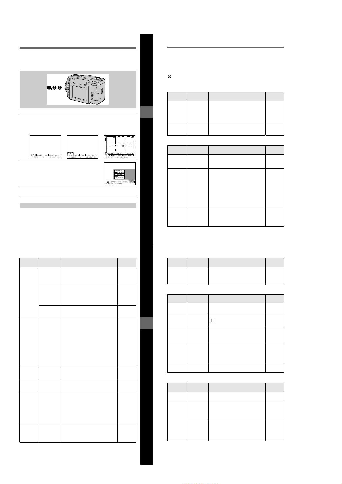
How to use the MODE selector
The MODE selector selects whether you can use your camera to record or to play
back and edit images. Set the selector as follows before starting to operate your
camera.
PLAY
PLAY
STILL
STILL
MOVIE
MOVIE
DSC-S50 DSC-S30
PLAY: To play back or edit
STILL: To record still images
MOVIE: To record moving
How to use the control button
The control button is used to select the indicators, images and menus appearing on
the LCD screen of your camera. The operation methods that are frequently used for
“Advanced operations” are described below.
PLAY
PLAY
STILL
STILL
images
and voice memos
images
(DSC-S50 only)
Select Enter (OK)
27
Before performing advanced operations
28
Turning on/off the operation buttons (menu bar) on the LCD screen
Press v to display the menu bar
on the LCD screen.
Press V to clear the menu bar
from the LCD screen.
Note
You cannot clear the menu bar during INDEX screen display (page 45).
Selecting items and images on the LCD screen
Press v/V/b/B on the
1
control button to select the
item you want to set or the
image you want to display.
The color of the selected item or
the border of the selected image
changes from blue to yellow.
Press the center z to enter
2
the item.
Repeat steps 1 and 2 to execute
each function.
The “Advanced operations” section of this manual refers to selecting and
entering items by the above procedure as “Select [(item name)].”
Menu bar
29
30
1-7
Page 14
How to change the menu settings
Some of the advanced operations for your camera are executed by selecting menu
items displayed on the LCD screen with the control button.
MODE selector
Press v on the control button to display the menu bar.
1
The menu bar appears as follows according to the setting of the MODE
selector.
MOVIE/STILL PLAY (single mode) PLAY (INDEX mode)
Select the desired item with v/V/b/B on the
2
control button, then press the center z.
The color of the selected item changes from blue to
yellow, and when you press the center z, the modes
that can be set for that item are displayed.
Select the desired mode with v/V/b/B on the control button, then
3
press the center z.
To clear the menu
Press V on the control button until the LCD screen returns to the menu bar display in
step 1. To clear the menu bar, press V again.
Before performing advanced operations
Menu settings
Menu items that can be modified differ depending on the setting of the MODE
selector. The LCD screen shows only the items you can operate at the moment. Initial
settings are indicated with x.
(SELF TIMER)
Records with the self-timer (page 18).
EFFECT
Item Setting Description MODE
P.EFFECT SOLARIZE
DATE/
TIME
FILE
FORMAT OK Formats a “Memory Stick.” MOVIE
POS.
SENSOR
FILE
NUMBER
B&W
SEPIA
NEG.ART
x OFF
DAY&TIME
DATE
x OFF
Item Setting Description MODE
CANCEL Cancels formatting of a “Memory
ON Plays back images recorded with the
x OFF When this camera may be subject to
SERIES Assigns numbers to files in sequence
x NORMAL Resets the file numbering each time the
Sets the image special effects (page 44). MOVIE
Sets whether to insert the date and time
into the image (page 44).
Stick.”
camera on its side (vertical images) as
horizontal images. This function does
not work for images recorded in TEXT
mode.
vibration such as when you record
images from inside a moving car, set
this to OFF to prevent improper
horizontal/vertical judgement.
even if the “Memory Stick” is changed.
“Memory Stick” is changed.
selector
STILL
STILL
selector
STILL
PLAY
STILL
MOVIE
STILL
Item Setting Description MODE
IMAGE
SIZE
REC MODE TIFF Records a TIFF (uncompressed) file in
REC TIME
SET
ROTA TE
(in single
mode only)
SLIDE
SHOW
(in single
mode only)
PRINT
MARK
x 1600×1200
1600 (3:2)
1024×768
640×480
1472×1104
x 1280×960
1280 (3:2)
1024×768
640×480
320×240
x 160×112
TEXT Records a GIF file in black-and-white.
VOICE Records an audio file (with still image)
E-MAIL Records a small-size (320×240) JPEG
x NORMAL Records a JPEG file in the selected
15 SEC
10 SEC
x 5 SEC
INTERVAL
REPEAT Repeats the slide show.
START Starts the slide show.
CANCEL Cancels the slide show settings and
ON Marks the still images to be printed
x OFF Unmarks the print mark of the still
Selects the image size when recording
still images (DSC-S50 only).
Selects the image size when recording
still images (DSC-S30 only).
Selects the MPEG image size when
recording moving images (DSC-S50
only).
addition to the JPEG file.
in addition to the JPEG file (DSC-S50
only).
file in addition to the selected image
size.
image size.
Adjusts the recording time for moving
images (DSC-S50 only).
Rotates the still image. PLAY
—
Sets the slide show interval.
x 3 SEC/5 SEC/10 SEC/30 SEC/1 MIN
x ON/OFF
execution.
(page 53).
images.
selector
STILL
STILL
MOVIE
STILL
MOVIE
PLAY
PLAY
31
Before performing advanced operations
32
Item Setting Description MODE
PROTECT ON Protects images against accidental
x OFF Releases protection of images against
CAMERA
Item Setting Description MODE
DIGITAL
ZOOM
SHARPNESS
WHITE
BALANCE
FLASH
LEVEL
EXPOSURE +2.0 EV to
TOOL
COPY OK Copies an image (page 51). PLAY
RESIZE
(in single
mode only)
x ON Uses digital zoom. STILL
OFF Does not use digital zoom.
+2 to –2 Adjusts the sharpness of the image.
IN DOOR
OUT DOOR
HOLD
x AUTO
HIGH Makes the flash level higher than
x NORMAL Normal setting.
LOW Makes the flash level lower than normal.
–2.0 EV
Item Setting Description MODE
CANCEL Cancels copying of the image.
1600×1200
1024×768
640×480
x CANCEL
1472×1104
1280×960
1024×768
640×480
x CANCEL
erasure (page 49).
accidental erasure.
appears on the LCD screen except
when set to 0.
Sets the white balance (page 43). MOVIE
normal.
Adjusts the exposure. MOVIE
Changes the recorded still image size
(page 51) (DSC-S50 only).
Changes the recorded still image size
(page 51) (DSC-S30 only).
selector
PLAY
selector
STILL
STILL
STILL
STILL
selector
PLAY
PLAY
33
34
1-8
Page 15
SETUP
2,3
1
Item Setting Description MODE
DEMO xON/STBY
VIDEO
OUT
LANGUAG
E
CLOCK
SET
BEEP SHUTTER Turns off the beep only. (The shutter
LCD
BRIGHT
INDEX*
Displays six images at a time (PLAY (INDEX) mode) (page 45).
DELETE
OK Deletes the displayed image. PLAY
CANCEL Cancels deleting of the image.
OFF
x NTSC Sets the video output signal to NTSC
PAL Sets the video output signal to PAL
/
x ENGLISH Displays the menu items in English. MOVIE
x ON Turns on the beep/shutter sound (when
OFF Turns off the beep/shutter sound.
Setting Description MODE selector
Displayed only when you use the AC
power adaptor in MOVIE or STILL
mode. When ON is selected, a
demonstration will start if you do not
operate your camera for about
10 minutes. To stop the demonstration,
turn off your camera. Select ON to make
the demonstration appear again.
mode (North American countries, Japan,
etc.).
mode (European countries, etc.).
/JPN Displays the menu items in Japanese.
Sets the date and time (page 13). MOVIE
—
sound is heard when you press the
shutter button.)
you press the control button/
button).
Adjusts the LCD screen brightness
using the +/– buttons on the LCD
screen. This has no effect on the
recorded images.
shutter
selector
MOVIE
STILL
MOVIE
STILL
PLAY
STILL
PLAY
STILL
PLAY
MOVIE
STILL
PLAY
MOVIE
STILL
PLAY
3 (RETURN)**
Returns to PLAY (single) mode.
∗ Displayed only in PLAY (single) mode.
∗∗Displayed only in PLAY (INDEX) mode.
Before performing advanced operations
B
V arious recor ding
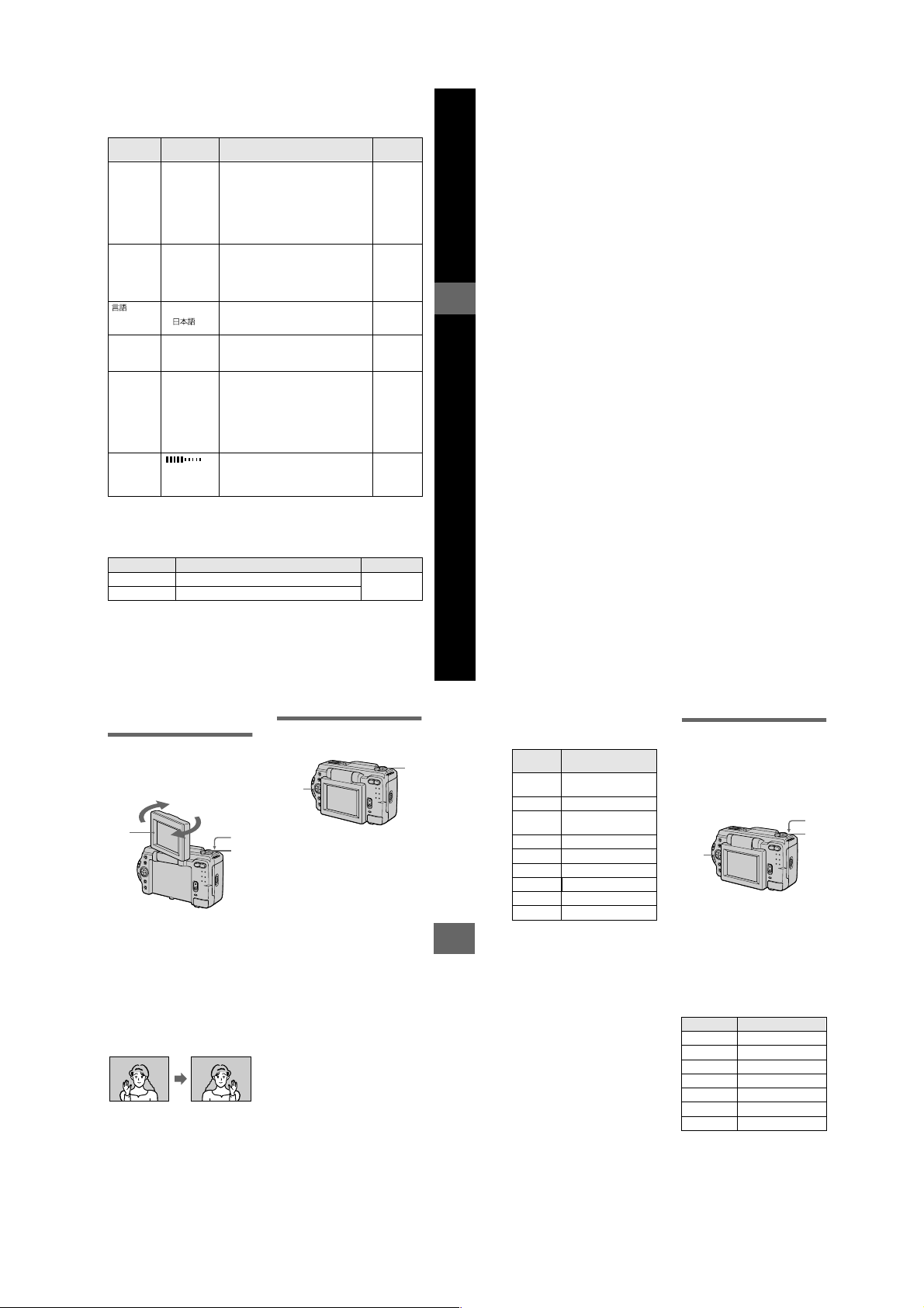
Rotating the LCD screen —
Face-to-Face recording
You can record images with the lens
facing you.
2
1
Set the MODE selector to
MOVIE or STILL.
2
Adjust the angle of the LCD
screen.
Rotate the LCD screen by 180° for
Face-to-Face recording.
3
Record the image.
The image appears on the LCD
screen as a mirror image, but the
recorded image is the same as the
actual subject.
Image appearing
on the LCD screen
Recorded image
Setting the image size
(IMAGE SIZE)
3
1
1
2
3
Set the MODE selector to
MOVIE or STILL.
(MOVIE is for DSC-S50 only)
Select [FILE] and then
[IMAGE SIZE] from the menu.
Select the desired image
size.
DSC-S50:
Still image sizes
1600×1200, 1600 (3:2),
1024×768, 640×480
Moving image sizes
320×240, 160×112
DSC-S30:
Still image sizes
1472×1104, 1280×960, 1280
(3:2), 1024×768, 640×480
35
B
Various recording
36
The number of images or the time
that you can record on a “Memory
Stick” (4 MB):
Image size Number of images or
1600× 120
0
1600 (3:2) Approx. 4
1472×110
4
1280×960 Approx. 6
1280 (3:2) Approx. 6
1024×768 Approx. 10
640×480 Approx. 57
320×240 Approx. 42 (15**) sec.
160×112
∗ When [REC MODE] is set to
[NORMAL].
∗∗Numbers in parentheses indicate the
maximum recording time during
continuous recording.
When [1600 (3:2)], [1280 (3:2)] is
selected
The image is recorded in 3:2 size to
match the printing paper size ratio of
3:2.
time*
Approx. 4
Approx. 5
Approx. 169 (60**) sec.
Recording still images for email (E-MAIL)
E-MAIL mode records a small-size
(320×240) image at the same time as a
still image. Small-size images are
convenient for e-mail transmission,
etc.
3
1
2
1
Set the MODE selector to
STILL.
2
Select [FILE], [REC MODE],
and then [E-MAIL] from the
menu.
3
Record the image.
The number of images that you can
record on a “Memory Stick” (4 MB)
in E-MAIL mode.
Image size Number of images
1600×1200 Approx. 3
1600 (3:2) Approx. 3
1472×1104 Approx. 4
1280×960 Approx. 5
1280 (3:2) Approx. 5
1024×768 Approx. 9
640×480 Approx. 46
To return to normal recording mode
Select [NORMAL] in step 2.
37
38
1-9
Page 16
Adding audio files to still
2
1
3
2
1
images (VOICE) (DSC-S50
only)
3
1
2
1
Set the MODE selector to
STILL.
2
Select [FILE], [REC MODE],
and then [VOICE] from the
menu.
3
Record the image.
If you press and release the shutter
button, sound is recorded for
5 seconds.
If you hold down the shutter
button, sound is recorded until you
release the shutter button for up to
40 seconds.
The number of images that you can
record on a “Memory Stick” (4 MB)
in VOICE mode (when recording
sound for five seconds):
Image size Number of images
1600×1200 Approx. 3
1600 (3:2) Approx. 3
1024×768 Approx. 8
640×480 Approx. 28
To return to normal recording mode
Select [NORMAL] in step 2.
When using the DSC-S30
The DSC-S30 does not have a VOICE
function. When you edit (delete, protect, or
copy files, etc.) files recorded in VOICE
mode on a different camera, the still image
file is edited but the audio file is not.
Recording text documents
(TEXT)
Text is recorded in black and white
GIF format to provide a clearer image.
1
Set the MODE selector to
STILL.
2
Select [FILE], [REC MODE],
and then [TEXT] from the
menu.
3
Record the image.
The number of images that you can
record on a “Memory Stick” (4 MB)
in TEXT mode:
Image size Number of images
1600×1200 Approx. 12 to 87
1600 (3:2) Approx. 14 to 97
1472×1104 Approx. 14 to 97
1280×960 Approx. 20 to 114
1280 (3:2) Approx. 22 to 137
1024×768 Approx. 30 to 160
640×480 Approx. 80 to 363
To return to normal recording mode
Select [NORMAL] in step 2.
Notes
• If the subject is not evenly illuminated, you
may be unable to record a clear image.
• Writing and reading data takes more time
than in normal recording.
• The flash does not strobe in TEXT mode
regardless of the surrounding brightness.
39
B
Various recording
Recording uncompressed
images (TIFF)
This mode simultaneously records still
images in both TIFF format
(uncompressed) and JPEG format
(compressed).
3
1
2
Set the MODE selector to
1
STILL.
Select [FILE], [REC MODE],
2
and then [TIFF] from the
menu.
3 Record the image.
The number of images that you can
record on a “Memory Stick”
(16 MB) in TIFF mode:
Image size Number of images
1600×1200 Approx. 2
1600 (3:2) Approx. 2
1280×960 Approx. 3
1280 (3:2) Approx. 3
To return to normal recording mode
Select [NORMAL] in step 2.
40
Notes
• JPEG images are recorded in the image
size selected by the [IMAGE SIZE] menu.
TIFF images are recorded in [1600×1200]
size in DSC-S50, and [1280×960] size in
DSC-S30 other than when [1600 (3:2)] or
[1280 (3:2)] is selected.
• Writing data takes more time than in
normal recording.
• The supplied “Memory Stick” (4 MB)
does not have sufficient capacity to record
uncompressed images.
Recording images in macro
2
1 Set the MODE selector to
MOVIE or STILL.
2 Press FOCUS repeatedly
until the (auto macro)
indicator appears on the LCD
screen.
You can record a subject as close
as about 1 3/16 inches (3 cm) from
the lens surface with the zoom set
all the way to the W side.
To return to normal recording mode
Press FOCUS repeatedly until
disappears from the LCD screen.
Notes
• You cannot record images in macro with
the following PROGRAM AE modes.
— Landscape mode
— Panfocus mode
• You cannot record images in macro when
appears on the LCD screen.
Setting the distance to the
subject
1
Normally the focus is automatically
adjusted. This function is useful when
the auto focus does not work well such
as in dark places.
Using the PROGRAM AE
function
1
+/–
2
1
Set the MODE selector to
MOVIE or STILL.
2
Press PROGRAM AE
Set the MODE selector to
1
MOVIE or STILL.
Press FOCUS repeatedly to
2
achieve a sharp focus.
The 9 (manual focus) indicator
appears on the LCD screen.
You can select from the following
7 focus settings: auto (no
indicator), (auto macro),
1 3/4 feet (0.5m), 3 1/4 feet
(1.0m), 9 3/4 feet (3.0m), 23 feet
(7.0m), ∞ (infinite)
To reactivate auto focusing
Press FOCUS repeatedly until the
indicator disappears in step 2.
Note
These setting distances are approximate, and
should be used as a reference.
41
B
Various recording
repeatedly to select the
desired PROGRAM AE mode.
A
Aperture priority mode
Makes the subject stand out
against an unclear background or
makes both the subject and the
background stand out clearly.
Press +/– repeatedly to select an
aperture value in 9 steps from F2.8
to F11.
S
Shutter speed priority
mode
Records a sharp picture of a fastmoving subject or the flow of
motion of a moving subject.
Press +/– repeatedly to select a
shutter speed in 18 steps from 8”
to 1/725 when recording a still
image and in 12 steps from 1/8 to
1/725 when recording a moving
image.
Twilight mode
Suppresses the washed-out color
of a bright subject in a dark place
so that you can record the subject
without losing the dark
atmosphere of the surroundings.
Twilight plus mode
Increases the effectiveness of the
twilight mode function.
42
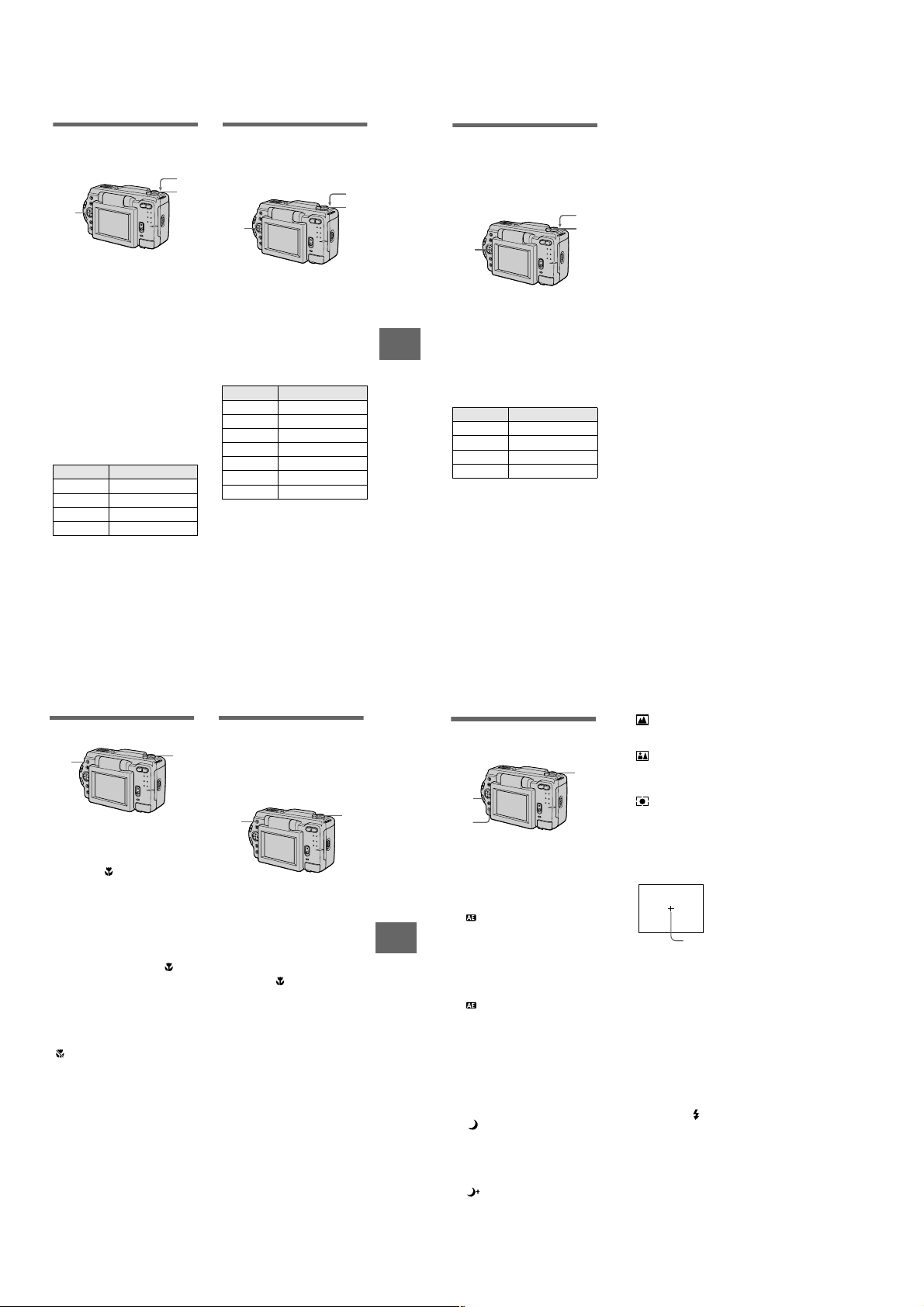
Landscape mode
Focuses only on a distant subject
to record landscapes, etc.
Panfocus mode
Changes the focus quickly and
simply from a close subject to a
distant subject.
Spot light-metering mode
Select this mode when there is
backlight or when there is strong
contrast between the subject and
the background, etc. Position the
point you want to record on the
spot light-metering cross hair.
LCD screen
Spot light-metering
cross hair
To cancel PROGRAM AE
Press PROGRAM AE repeatedly until
the indicator on the LCD screen goes
out.
Notes
• You cannot select F2.8 in aperture priority
mode when the zoom is set to the T side.
• You can focus only on distant subjects in
Landscape mode.
• In Panfocus mode, the zoom position and
focus are fixed.
• When you record in the Twilight plus
mode, we recommend that you use a tripod
to prevent shaking.
• Set the forced flash when you use the
flash in the following modes:
Twilight mode
–
–
Twilight plus mode
–
Landscape mode
• You cannot use the PROGRAM AE
function when [REC MODE] is set to
[TEXT].
• If the setting is not appropriate in aperture
priority mode and shutter priority mode,
the setting value indicator on the LCD
screen flashes when you press the shutter
button. In this case, reset the value.
1-10
Page 17
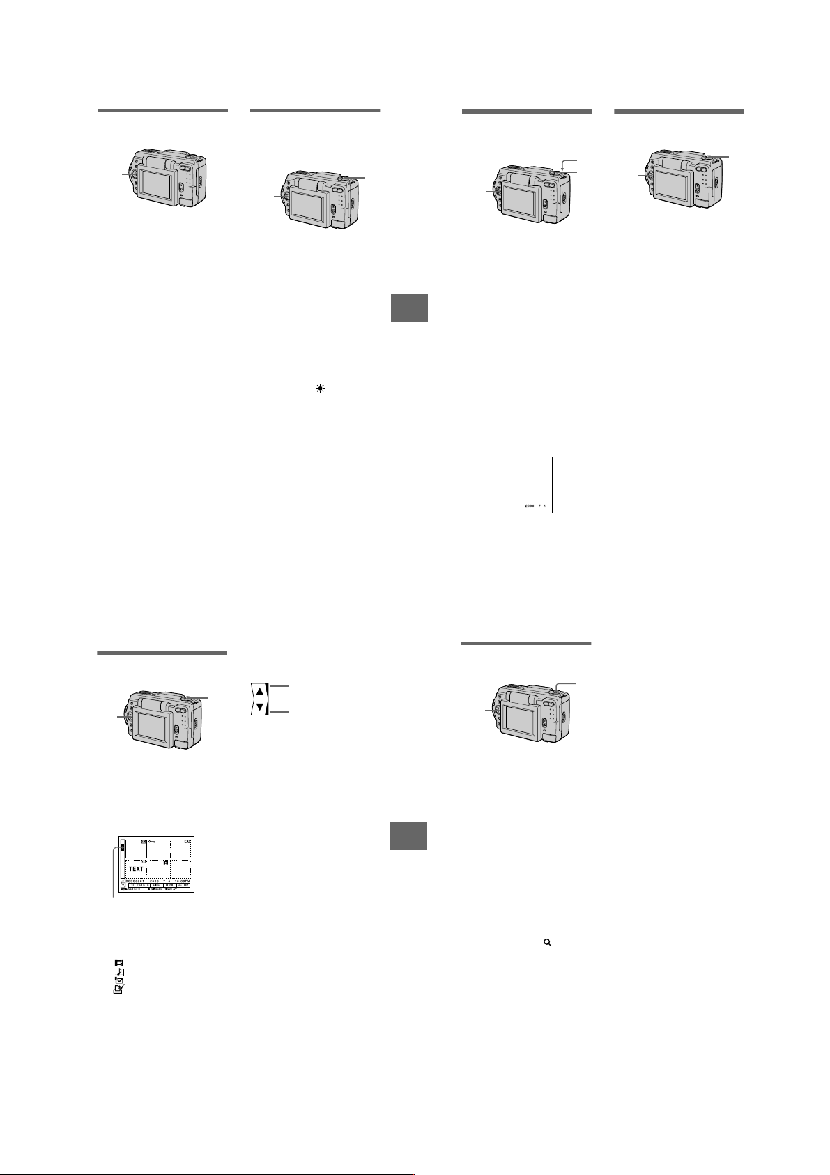
Adjusting the exposure
2,3
1
Displays the previous
index screen
Displays the next index
screen
(EXPOSURE)
1
2,3
1
Set the MODE selector to
MOVIE or STILL.
2
Select [CAMERA] and then
[EXPOSURE] from the menu.
3
Select the desired exposure
value.
Adjust the exposure value while
checking the brightness of the
background. You can select values
ranging from +2.0 EV to –2.0 EV
in steps of 1/3 EV.
Note
The exposure may not be adjusted properly
when the subject is extremely bright or dark,
or when using the flash.
Adjusting the white balance
(WHITE BALANCE)
Normally the white balance is
automatically adjusted.
1
Set the MODE selector to
MOVIE or STILL.
2
Select [CAMERA] and then
[WHITE BALANCE] from the
menu.
3
Select the desired white
balance setting.
IN DOOR (n)
• Places where the lighting
condition changes quickly
• Under bright lighting such as
photography studios
• Under sodium or mercury lamps
OUT DOOR ( )
Recording a sunrise/sunset, night
scene, neon signs, or fireworks
HOLD
Recording a single-colored subject
or background
AUTO (No indicator)
Adjusts the white balance
automatically
To reactivate auto adjustment
Select [AUTO] in step 3.
Note
Select [AUTO] when recording under
fluorescent lighting.
B
Various recording
Recording the date and time
on the still image (DATE/
TIME)
2,3
1
Set the MODE selector to
STILL.
2
Select [EFFECT] and then
[DATE/TIME] from the menu.
Select the date and time
3
setting.
DAY&TIME
The date, hour and minutes are
imposed onto the image.
DATE
The year, month and day are
imposed onto the image.
OFF
The date and time are not imposed
onto the image.
4
Record the image.
The date and time are not
displayed during recording.
The date and time are displayed
when playing back images.
Enjoying picture effects
(P.EFFECT)
4
1
2,3
1
Set the MODE selector to
MOVIE or STILL.
2
Select [EFFECT] and then
[P.EFFECT] from the menu.
3
Select the desired mode.
SOLARIZE
The light contrast is clearer and the
picture looks like an illustration.
B&W
The picture is monochrome (black
and white).
SEPIA
The picture is colored like an old
picture.
NEG.ART
The color and brightness of the
picture are reversed.
To cancel picture effect
Select [OFF] in step 3.
1
V arious playback
B
Playing back six images at
once (INDEX)
2
1 Set the MODE selector to
PLAY.
Select [INDEX] on the LCD
2
screen.
Six images are displayed at once
(index screen).
This shows the position of the
currently displayed images relative
to all the recorded images.
The following marks are displayed
on each image according to the
image type and settings.
: Moving image file
: V oice memo file
: E-mail file
: Print mark
- : Protect mark
TEXT: T ext mark
TIFF: TIFF mark
(No mark): Normal recording (no
settings)
To display the next (previous) index
screen
Select v/V at the lower left of the LCD
screen.
1
To return to normal playback (single
image)
• Select the desired image with the
control button.
• Select [3] (RETURN).
Note
You cannot display images recorded in
TEXT mode on the INDEX screen.
43
44
Notes
Enlarging a part of the still
image (Zoom and trimming)
2,4
1
Set the MODE selector to
PLAY.
2
Display the image to be
enlarged.
3
Zoom in/out the image with
the zoom button.
The zoom scaling indicator
appears on the LCD screen.
Press the control button
B
Various playback
4
repeatedly to select the
desired part of the image.
v: The image moves downward
V: The image moves upward
b: The image moves rightward
B: The image moves leftward
To return to the normal size
Zoom in with the zoom button until the
zoom scaling indicator ( × 1.1)
disappears from the screen, or simply
press z.
To record an enlarged image
(trimming)
1Enlarge the image.
2Press the shutter button. The image
is recorded at 640×480 size, then the
display returns to the image display
before enlargement.
• You cannot trim images recorded in TEXT
mode or uncompressed images.
• The maximum zoom magnification is 5
the original image, regardless of the image
1
size.
• The picture quality of trimmed images
may deteriorate.
3
• The original picture remains even after
trimming.
• The trimmed image is recorded as the
newest file.
×
45
46
1-11
Page 18
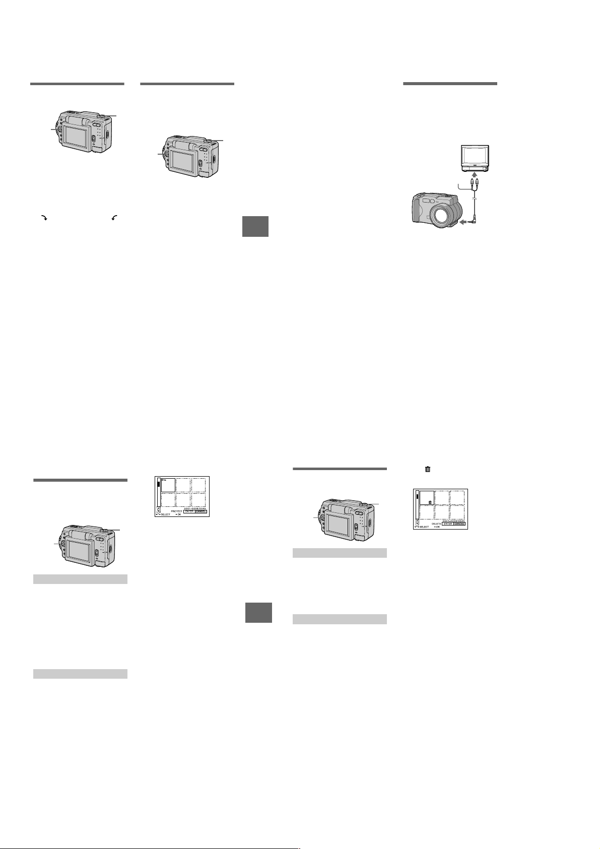
Rotating a still image
2,3
1
(ROTATE)
2,3,4
1 Set the MODE selector to
PLAY.
2 Display the image to rotate.
3 Select [FILE] and then
[ROTATE] from the menu.
Rotate the image clockwise
4
or counterclockwise ,
then select [RETURN].
Notes
• You may not be able to rotate protected
images or images recorded with other
equipment.
• Also, when viewing images on a personal
computer, the image rotation information
may not be reflected depending on the
application software.
• You cannot rotate protected or
uncompressed images, or images recorded
in TEXT mode.
Playing back the images in
order (SLIDE SHOW)
This function is useful for checking the
1
recorded images or for presentations,
etc.
Set the MODE selector to
1
PLAY.
Select [FILE] and then [SLIDE
2
SHOW] from the menu.
Set the following items.
INTERVAL
1 MIN (one minute), 30 SEC
(30 seconds), 10 SEC
(10 seconds), 5 SEC (5 seconds),
3 SEC (3 seconds)
REPEAT
ON: Plays back images in a
continuous loop until
[RETURN] is selected.
OFF: After all images have been
played back, the slide show
ends.
3 Select [START] with the
control button.
The slide show begins.
To cancel the slide show
Select [CANCEL] in step 2 or 3.
To skip to the next/previous image
during slide show playback
b/B
at the lower left of the LCD
Select
screen.
47
Note
The [INTERVAL] setting time is
approximate, and may vary depending on
the played back image size or other factors.
B
Various playback
48
Viewing images on a TV
screen
Before connecting your camera, be
sure to turn off the TV. After
connecting A/V connecting cable
(DSC-S50) or VIDEO connecting
cable (DSC-S30), turn on the TV.
Set the TV/VIDEO
switch to VIDEO.
A/V connecting cable or
VIDEO connecting cable
(supplied)
to A/V OUT jack or
VIDEO OUT jack
1 Connect your camera and the
TV.
DSC-S50
Connect the A/V connecting cable
to the A/V OUT jack of your
camera and to the audio/video
input jacks of the TV.
If your TV has stereo type audio
input jacks, connect the audio plug
of the A/V connecting cable to the
Lch jack.
DSC-S30
Connect the video cable to the
VIDEO OUT jack of your camera
and to the video input jack of the
TV.
2 Turn on the TV, then start
playback on your camera.
The playback image appears on
the TV screen.
Note
You cannot use a TV that has an antenna
(aerial) connector only.
Editing
B
Preventing accidental erasure
(PROTECT)
The - (protect) indicator appears on
protected images.
1,2,3
In single mode
Set the MODE selector to
1
PLAY, then display the image
to protect.
2 Select [FILE], [PROTECT],
and then [ON] from the menu.
The displayed image is protected
and - appears.
To release protection
Select [OFF] in step 2.
In INDEX mode
1 Set the MODE selector to
PLAY, then display the INDEX
screen.
Select [FILE], [PROTECT],
2
and then [ALL] or [SELECT]
from the menu.
3 When you select [ALL]
Select [ON].
All the images recorded in
“Memory Stick” are protected.
When you select [SELECT]
Select all the images to protect
with the control button, then select
[ENTER].
The selected images are protected.
1
To release protection
If you selected [ALL] in step 2, select
[OFF]. If you selected [SELECT] in
step 2, select the images to unprotect
with the control button, then select
[ENTER].
B
Editing
Deleting images (DELETE)
You cannot delete protected files.
1,2,3
In single mode
1 Set the MODE selector to
PLAY, then display the image
to delete.
Select [DELETE] and then
2
[OK] from the menu.
The image is deleted.
In INDEX mode
Set the MODE selector to
1
PLAY, then display the INDEX
screen.
2 Select [DELETE] and then
[ALL] or [SELECT] from the
menu.
3 When you select [ALL]
Select [ENTER].
All unprotected images are
deleted.
When you select [SELECT]
Select all the images to delete with
the control button, then select
[ENTER].
The (delete) indicator appears
on the selected images and these
images are deleted.
1
To cancel deleting
Select [CANCEL] in step 2 or 3.
Note
If there are files on the “Memory Stick” with
names having the same last 4 digits as the
file name of the image to be deleted, these
files are also deleted at the same time.
49
50
1-12
Page 19
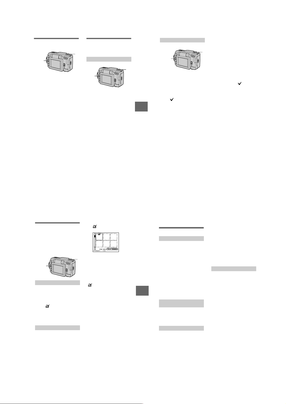
Changing the recorded still
1,2
1
52
1 Set the MODE selector to
PLAY, then display the INDEX
screen.
2 Select [TOOL], [COPY], and
then [SELECT] from the
menu.
3 Select the image to copy.
The (select) indicator appears
on the image.
4 Select [ENTER].
“MEMORY STICK ACCESS”
appears.
5 When “CHANGE MEMORY
STICK” is displayed, eject the
“Memory Stick.”
“INSERT MEMORY STICK”
appears.
6 Insert another “Memory
Stick.”
“RECORDING” appears. When
copying is completed,
“COMPLETE” appears.
If you exchange the “Memory
Stick,” the same image is copied
again.
In INDEX mode
After copying is finished
Select [EXIT].
If you do not select [EXIT], the same
image is copied each time you
exchange the “Memory Stick.”
To cancel copying part-way
Change the MODE selector setting or
turn off the power.
Notes
• You cannot copy uncompressed images.
• You cannot copy images that are bigger
than 1.4 MB at once. If “NOT ENOUGH
MEMORY” appears or flashes on the
INDEX screen, cancel some images to
copy and try again.
image size (RESIZE)
1,2,3
1 Set the MODE selector to
PLAY and display the image
to resize.
2 Select [TOOL] and then
[RESIZE] from the menu.
3 Select the desired image
size.
DSC-S50
1600×1200, 1024×768, 640 ×480
DSC-S30
1472×1104, 1280×960,
1024×768, 640×480
The changed image is recorded,
then the display returns to the
image display before resizing.
To return to the original size
Select [CANCEL] in step 3.
Notes
• You cannot change the size of images
recorded in TEXT mode or uncompressed
images.
• When you change from a small size to a
large size, the picture quality deteriorates.
• The original image is retained even after
resizing.
• The resized image is recorded as the
newest file.
Copying images (COPY)
You can copy images to another
“Memory Stick.”
1
In single mode
Set the MODE selector to
1
PLAY, then display the image
to copy.
2 Select [TOOL], [COPY], and
then [OK] from the menu.
“FILE ACCESS” appears.
When “CHANGE MEMORY
3
STICK” appears, eject the
“Memory Stick.”
“INSERT MEMORY STICK”
appears.
Insert the “Memory Stick” on
4
which to copy the image.
“RECORDING” appears. When
copying is completed,
“COMPLETE” appears.
If you exchange the “Memory
Stick,” the same image is copied
again.
After copying is finished
Select [EXIT].
If you do not select [EXIT], the same
image is copied each time you
exchange the “Memory Stick.”
B
Editing
1
,2,3,4
Selecting still images to print
(PRINT MARK)
You can mark a print mark on still
images recorded with your camera.
This mark is convenient when you
have images printed at a shop that
conforms with the DPOF (Digital Print
Order Format) standard.
,2,3,4
In single mode
1 Set the MODE selector to
PLAY and display the image
you want to print.
Select [FILE], [PRINT MARK],
2
and then [ON] from the menu.
The (print) mark is displayed
on the image.
To unmark the print mark
Select [OFF] in step 2.
In INDEX mode
1 Set the MODE selector to
PLAY, then display the INDEX
screen.
2 Select [FILE], [PRINT MARK],
and then [SELECT] from the
menu.
3 Select the images to mark
with the control button.
Select [ENTER].
4
of the selected images change
from green to white.
To unmark selected print marks
1
Select the images to unmark in step 3
with the control button, then select
[ENTER].
To unmark all the print marks
Select [FILE], [PRINT MARK],
[ALL] and then [OFF] from the menu.
of all images are unmarked.
Notes
• You cannot mark moving images or
images recorded in TEXT mode.
• If you mark an image recorded in TIFF
mode with a print mark, only the
uncompressed image is printed, and the
JPEG image recorded at the same time is
not printed.
51
B
Editing
Additional information
Precautions
On cleaning
Cleaning the LCD screen
Wipe the screen surface with a cleaning
cloth (not supplied) or a LCD cleaning kit
(not supplied) to remove fingerprints, dust,
etc.
Cleaning the camera surface
Clean the camera surface with a soft cloth
slightly moistened with water, then wipe the
surface dry. Do not use any type of solvent
such as thinner, alcohol or benzene as this
may damage the finish or the casing.
After using your camera at the
seashore or other dusty locations
Clean your camera carefully. Otherwise, the
salty air may corrode the metal fittings or
dust may enter the inside of your camera,
causing a malfunction.
Note on operating
temperature
Your camera is designed for use between the
temperatures of 32˚F and 104˚F (0˚C and
40˚C). Recording in extremely cold or hot
places that exceed this range is not
recommended.
On moisture condensation
If the camera is brought directly from a cold
to a warm location, or is placed in a very
damp room, moisture may condense inside
or outside the camera. Should this occur, the
camera will not operate properly.
Moisture condensation occurs
easily when:
• The camera is brought from a cold location
such as a ski slope into a warmly heated
room.
• The camera is taken from an air-
conditioned room or car interior to the hot
outdoors, etc.
How to prevent moisture
condensation
When bringing the camera from a cold place
to a warm place, seal the camera in a plastic
bag and allow it to adapt to conditions at the
new location over a period of time (about an
hour).
If moisture condensation occurs
Turn off the camera and wait about an hour
for the moisture to evaporate. Note that if
you attempt to record with moisture
remaining inside the lens, you will be
unable to record clear images.
On AC power adaptor
• Unplug the unit from the wall outlet
(mains) when you are not using the unit for
a long time.
• To disconnect the power cord (mains lead),
pull it out by the plug. Never pull the
power cord (mains lead) itself.
• Do not operate the unit with a damaged
cord or if the unit has been dropped or
damaged.
• Do not bend the power cord (mains lead)
forcibly, or place a heavy object on it. This
will damage the cord and may cause fire or
electrical shock.
• Prevent metallic objects from coming into
contact with the metal parts of the
connecting section. If this happens, a short
may occur and the unit may be damaged.
• Always keep metal contacts clean.
• Do not disassemble the unit.
• Do not apply mechanical shock or drop the
unit.
• While the unit is in use, particularly during
charging, keep it away from AM receivers
and video equipment. AM reception and
video operation are disturbed.
• The unit becomes warm during use. This is
not a malfunction.
• Do not place the unit in locations that are:
—Extremely hot or cold
—Dusty or dirty
—Very humid
—Vibrating
53
54
1-13
Page 20
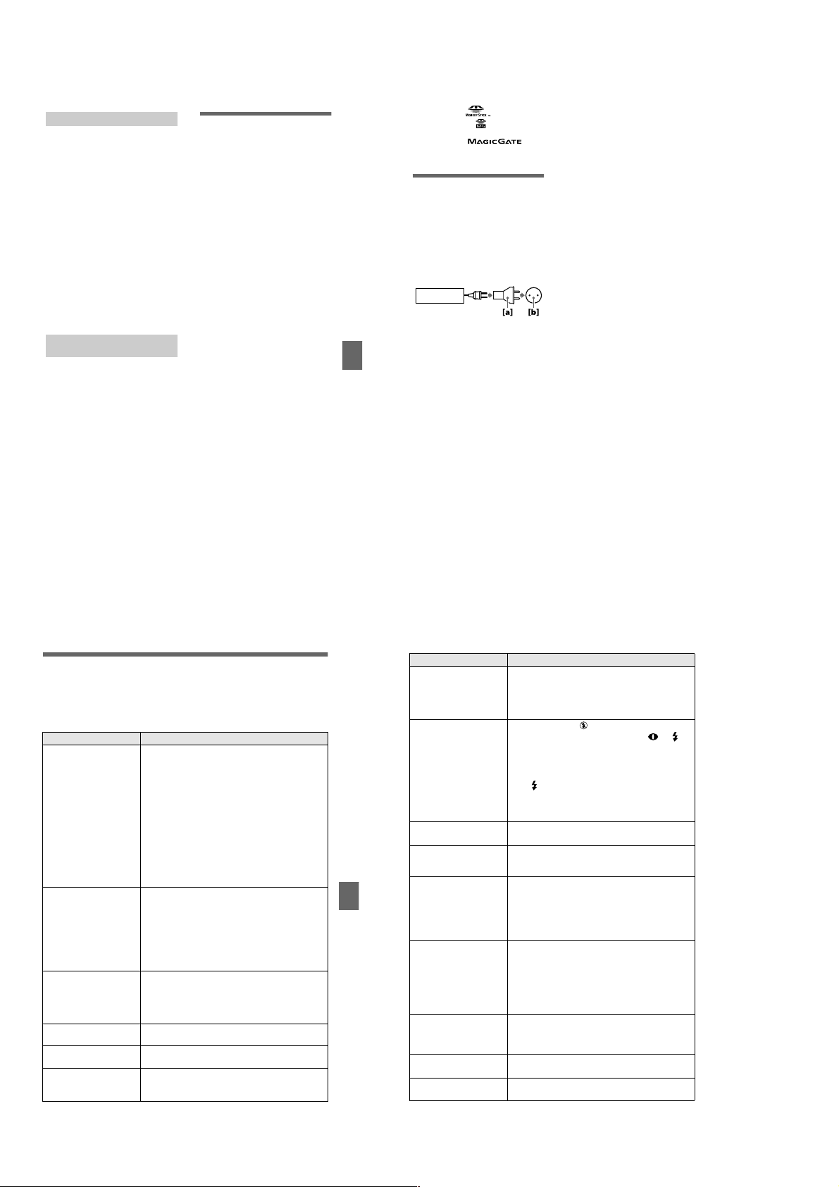
On battery pack
• Use only the specified charger with the
charging function.
• To prevent accident from a short circuit, do
not allow metal objects to come into
contact with the battery terminals.
• Keep the battery pack away from fire.
• Never expose the battery pack to
temperatures above 140˚F (60˚C), such as
in a car parked in the sun or under direct
sunlight.
• Keep the battery pack dry.
• Do not expose the battery pack to any
mechanical shock.
• Do not disassemble nor modify the battery
pack.
• Install the battery pack to the camera
securely.
• Charging while some capacity remains
does not affect the original battery
capacity.
If any problem occurs, unplug your camera
and contact your nearest Sony dealer.
On internal rechargeable
button battery
This camera has an internal rechargeable
button battery for maintaining the date and
time and other settings regardless of
whether the power is on or off. This
rechargeable button battery is constantly
charged as long as you are using the camera.
However, if you use the camera for only
short periods it discharges gradually, and if
you do not use the camera at all for about
half a year it becomes completely
discharged. In this case, be sure to charge
this rechargeable button battery before using
the camera.
However, even if this rechargeable button
battery is not charged, you can still use the
camera as long as you do not record the date
and time.
Charging method
Connect the camera to a wall outlet (mains)
with the AC power adaptor, or install a
charged battery pack, and leave the camera
for 24 hours or more with the POWER
switch set to OFF.
On “Memory Sticks”
“Memory Stick” is a new compact, portable
and versatile IC recording medium with a
data capacity that exceeds a floppy disk.
“Memory Stick” is specially designed for
exchanging and sharing digital data among
“Memory Stick” compatible products.
Because it is removable, “Memory Stick”
can also be used for external data storage.
There are two types of “Memory Sticks”:
general “Memory Sticks” and “MagicGate
Memory Sticks” that are equipped with the
MagicGate* copyright protection
technology.
You can use both types of “Memory Stick”
with your camera. However, because your
camera does not support the MagicGate
standards, data recorded with your camera is
not subject to MagicGate copyright
protection.
∗ MagicGate is copyright protection
technology that uses encryption
technology.
Notes
• Do not remove the “Memory Stick” while
reading or writing data.
• Data may be damaged if:
—you remove the “Memory Stick” or turn
off your camera while reading or
writing data.
—you use the “Memory Stick” in a
location subject to the effects of static
electricity or noise.
• Do not attach any other material than the
supplied label on the labeling position.
• Attach the label so that it does not stick out
from the proper attachment location.
• When you carry or store the “Memory
Stick,” put it in its supplied case.
• Do not touch the terminals of a “Memory
Stick” with your hand or a metal object.
• Do not strike, bend or drop the “Memory
Stick.”
• Do not disassemble or modify the
“Memory Stick.”
• Do not allow the “Memory Stick” to get
wet.
55
Additional information
“Memory Stick”, , “MagicGate
Memory Stick” and are trademarks of
Sony Corporation.
“MagicGate” and are
trademarks of Sony Corporation.
Using your camera abroad
Power sources
You can use your camera in any
country or area with the supplied
battery charger within 100 V to 240 V
AC, 50/60 Hz. Use the supplied AC
power adaptor [a], if necessary,
depending on the design of the wall
outlet (mains) [b].
AC-L10
Watching the playback picture on
TV
If you want to view the playback
picture on a TV, you need a TV having
a video input jack and a video
connecting cable.
The color system of the TV must be
the same as that of your digital still
camera. TV color systems differ from
country to country. Check the
following list:
NTSC system countries
Bahama Islands, Bolivia, Canada,
Central America, Chile, Columbia,
Ecuador, Jamaica, Japan, Korea,
Mexico, Peru, Surinam, Taiwan, the
Philippines, the U.S.A., Venezuela, etc.
PAL system countries
Australia, Austria, Belgium, China,
Denmark, Finland, Germany, Great
Britain, Holland, Hong Kong, Italy,
Kuwait, Malaysia, New Zealand,
Norway, Portugal, Singapore, Spain,
Sweden, Switzerland, Thailand, etc.
56
PAL-M system country
Brazil
PAL-N system countries
Argentina, Paraguay, Uruguay
SECAM system countries
Bulgaria, Czech Republic, France,
Guiana, Hungary, Iran, Iraq, Monaco,
Poland, Russia, Slovak Republic,
Ukraine, etc.
Troubleshooting
If you experience trouble with your camera, first check the following items. Should
your camera still not operate properly after you have made these checks, consult your
Sony dealer or local authorized Sony service facility. If code displays (C:ss:ss)
appear on the LCD screen, the self-diagnosis display function is working (page 62).
Symptom Cause and/or Solution
Your camera does not
work.
Your camera cannot
record images.
The picture is out of focus. • Your camera is not in macro recording mode when
The resizing function does
not work.
You cannot display a print
mark.
The picture is noisy. • Your camera is placed near a TV or other
• You are not using an “InfoLITHIUM” battery pack.
t Use an “InfoLITHIUM” battery pack (page 8).
• The battery level is low (the E indicator appears
on the LCD screen).
t Charge the battery pack (page 9).
• The AC power adaptor is not connected securely.
t Connect it firmly to the DC IN jack of your
camera and a wall outlet (mains) (page 12).
• The built-in microcomputer is not working
properly.
t Disconnect and then reconnect all power
sources after one minute. Then turn the power
on by sliding the POWER switch down and
check that the camera works properly.
• The MODE selector is set to PLAY.
t Set it to MOVIE or STILL (pages 16, 20).
• No “Memory Stick” has been inserted into your
camera.
t Insert a “Memory Stick” (page 15).
• The write-protect tab on the “Memory Stick” is set
to LOCK.
t Set it to the recording position.
you shoot a subject that is about 1 3/16 to
9 7/8 inches (3 to 25 cm) away from the lens.
t Set the macro recording mode (page 41).
t Press the zoom button to set to the W side.
• You cannot resize moving images and text images.
• You cannot display print marks on moving images
and text images.
equipment that uses strong magnets.
t Move your camera away from the TV, etc.
Additional information
Symptom Cause and/or Solution
The picture is too dark. • You are shooting a subject with a light source
The flash does not work. • The flash is set to .
The date and time are
recorded incorrectly.
Vertical streaks appear
when you are shooting a
very bright subject.
The battery life is short. • You are recording/playing back images under
The battery remaining
indicator is incorrect.
Sufficient battery
remaining indicator is
displayed but the power
runs out soon.
The zoom does not work. • PROGRAM AE is set to the Panfocus mode.
Digital zoom does not
function.
behind the subject.
t Adjust the exposure (page 43).
t Adjust the brightness of the LCD screen (page
35).
t Set the flash to auto (no indicator), or
(page 19).
• PROGRAM AE is set to the Twilight, Twilight
plus, or Panfocus mode.
t Cancel the mode (page 42) or set the flash to
.
• The MODE selector is set to MOVIE (DSC-S50
only).
t Set it to STILL.
• The date and time are not set correctly.
t Set the correct date and time (page 13).
• The smear phenomenon is happening.
t This is not a malfunction.
extremely cold temperatures.
• The battery pack is not charged enough.
t Charge the battery pack fully.
• The battery pack is dead.
t Replace the battery pack with a new one.
• You have used the camera for a long time in an
extremely hot or an extremely cold location.
• The battery pack is dead.
t Replace the battery pack with a new one (page
8).
• The battery pack is discharged.
t Install a charged battery pack (pages 8, 9).
t Fully charge the battery pack (page 9).
t Cancel the Panfocus mode (page 42).
• You cannot use digital zoom to record moving
pictures.
57
58
1-14
Page 21
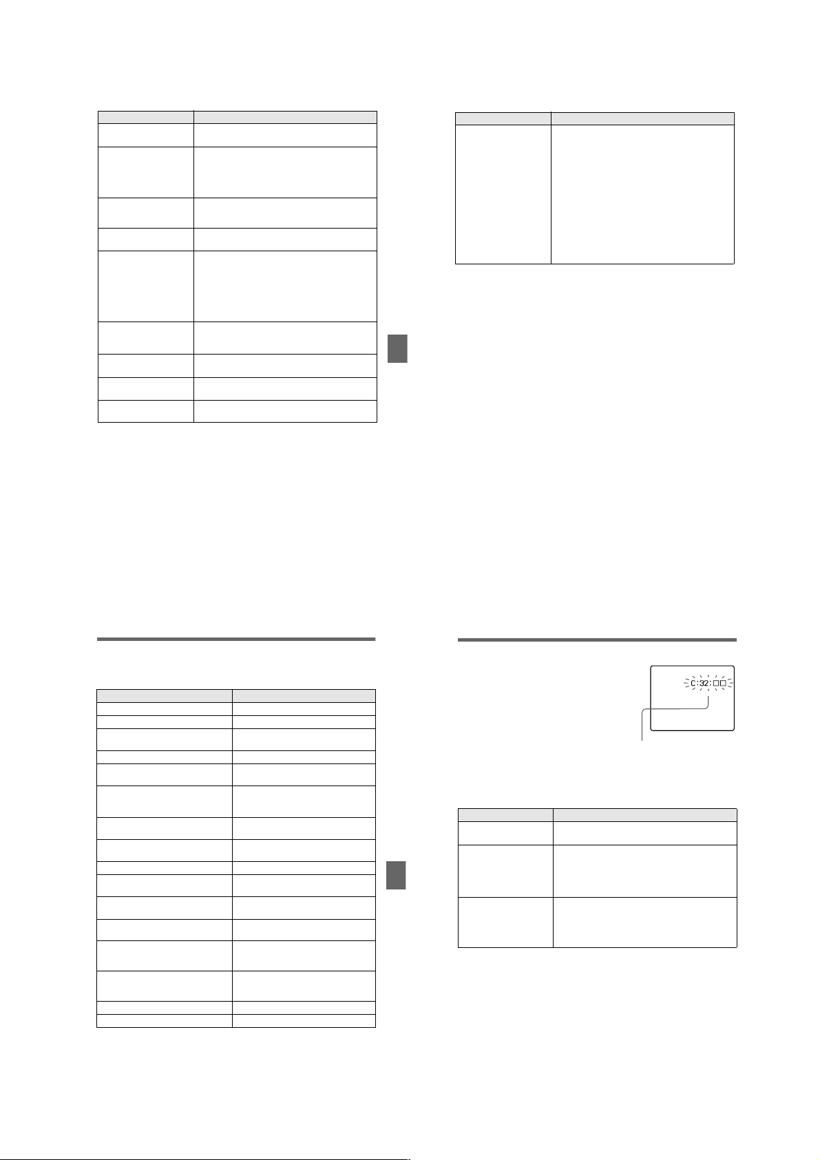
Symptom Cause and/or Solution
62
Self-diagnosis display
Your camera has a self-diagnosis display. This
function displays the camera condition on the
LCD screen with a combination of a letter and
four digits of numbers. If this occurs, check the
following code chart. The code informs you of the
camera’s current condition. The last two digits
(indicated by ss) will differ depending on the
state of the camera.
If you are unable to solve the problem even after trying the corrective
actions a few times, contact your Sony dealer or local authorized Sony
service facility.
First three digits Cause and/or Corrective Action
C:32:ss • There is trouble with your camera’s hardware.
t Turn the power off and on again.
C:13:ss • An unformatted “Memory Stick” is inserted.
t Format the “Memory Stick” (page 32).
• The inserted “Memory Stick” cannot be used with
your camera, or is damaged.
t Insert a new “Memory Stick” (page 15).
E:61:ss
E:91:ss
• A camera malfunction that you cannot reverse has
occurred.
t Contact your Sony dealer or local authorized
Sony service facility and inform them of the 5digit service code. (example: E:61:10)
Your camera cannot play
back images.
The image and sound
break off when you play
back an image on a
personal computer.
The image cannot be
played back on a personal
computer.
Your camera cannot delete
an image.
The power turns off
suddenly.
The image does not
appear on the TV screen.
A file error occurs when
you play back a file.
The PROGRAM AE
function does not work.
The LCD screen freezes
momentarily.
• The MODE selector is set to STILL or MOVIE.
t Set it to PLAY (page 21).
• You are playing back the file directly from the
“Memory Stick.”
t Copy the file to the hard disk of the personal
computer and then play back the file from the
hard disk (page 27).
t Consult the personal computer or software
manufacturer.
• The image is protected.
t Cancel the protection (page 49).
• With the MODE selector set to STILL or MOVIE,
if you do not operate the camera for about three
minutes while the power is on, the camera turns off
automatically to prevent wearing down the battery.
t Turn on the camera.
• The battery is discharged.
t Replace it with a charged battery.
• The video output signal setting of your camera is
incorrect.
t Change the setting (page 48).
• The image size is larger than 1600 ×1200.
t Use an image size of 1600×1200 or smaller.
• The camera is set to text mode.
t Cancel text mode (page 42).
• This is a characteristic of the system and is not a
malfunction.
Additional information
Symptom Cause and/or Solution
Your personal computer
does not recognize your
camera.
• The camera is turned off.
t Turn on the camera.
• The battery level is low.
t Use the AC power adaptor (page 12).
• The USB cable is not connected firmly.
t Disconnect the USB cable, and connect it again
firmly. Make sure that “PC MODE” is displayed
on the LCD screen (page 26).
• The USB connectors on your personal computer
are connected to other equipment besides the
keyboard, the mouse, and your camera.
t Disconnect the USB cables except for the ones
connected to the keyboard, the mouse, and your
camera (page 24).
Warning and notice messages
Various messages appear on the LCD screen. Check the corresponding descriptions
in the following list.
Message Meaning
NO MEMORY STICK No “Memory Stick” has been inserted.
SYSTEM ERROR Turn the power off and on again.
MEMORY STICK ERROR The inserted “Memory Stick” cannot be
FORMAT ERROR Failed to format the “Memory Stick.”
MEMORY STICK LOCKED The write-protect tab on the “Memory
NO MEMORY SPACE The capacity of the “Memory Stick” is
NO FILE No image has been recorded on the
FILE ERROR An error occurred while playing back the
FILE PROTECT The image is protected against erasure.
for “InfoLITHIUM” battery only The battery is not the “InfoLITHIUM”
NOT ENOUGH MEMORY The images you want to copy are too big
DIRECTORY ERROR A directory with the same name already
IMAGE SIZE OVER You are playing back an image of a size
INVALID OPERATION You are playing back a file that was
E
-
used with your camera, or is damaged.
Stick” is set to the LOCK position.
full, and you cannot record or copy
images.
“Memory Stick.”
image.
type.
to copy with your camera.
exists.
that cannot be played back with your
camera.
created on equipment other than your
camera.
The battery level is low or zero.
The image is protected.
59
Additional information
60
Self-diagnosis display
• C:ss:ss
You can reverse the camera
malfunction yourself.
• E:ss: ss
Contact your Sony dealer or local
authorized Sony service facility.
61
1-15
Page 22

LCD screen indicators
The indicators during recording
A Battery remaining indicator
B PROGRAM AE/flash level/flash
mode indicator
C White balance/EV level/
sharpness indicator
D Picture effect indicator
E Date/time indicator
F Aperture/shutter speed
indicator
G AE lock/focus lock indicator
H Recording mode indicator
I Image size indicator
64
J Self-diagnosis function/
recording time indicator
K Number of recorded images
L Remaining memory capacity
indicator
M Moving image/VOICE recor
time indicator (DSC-S50 only)
N Self-timer indicator
O Spot light-metering indicator
P Focus/macro mode indicator
Q Menu bar and guide menu
They appear by pressing v on the
control button and disappear by
pressing V of it.
ding
1-16 E
1-16
Page 23
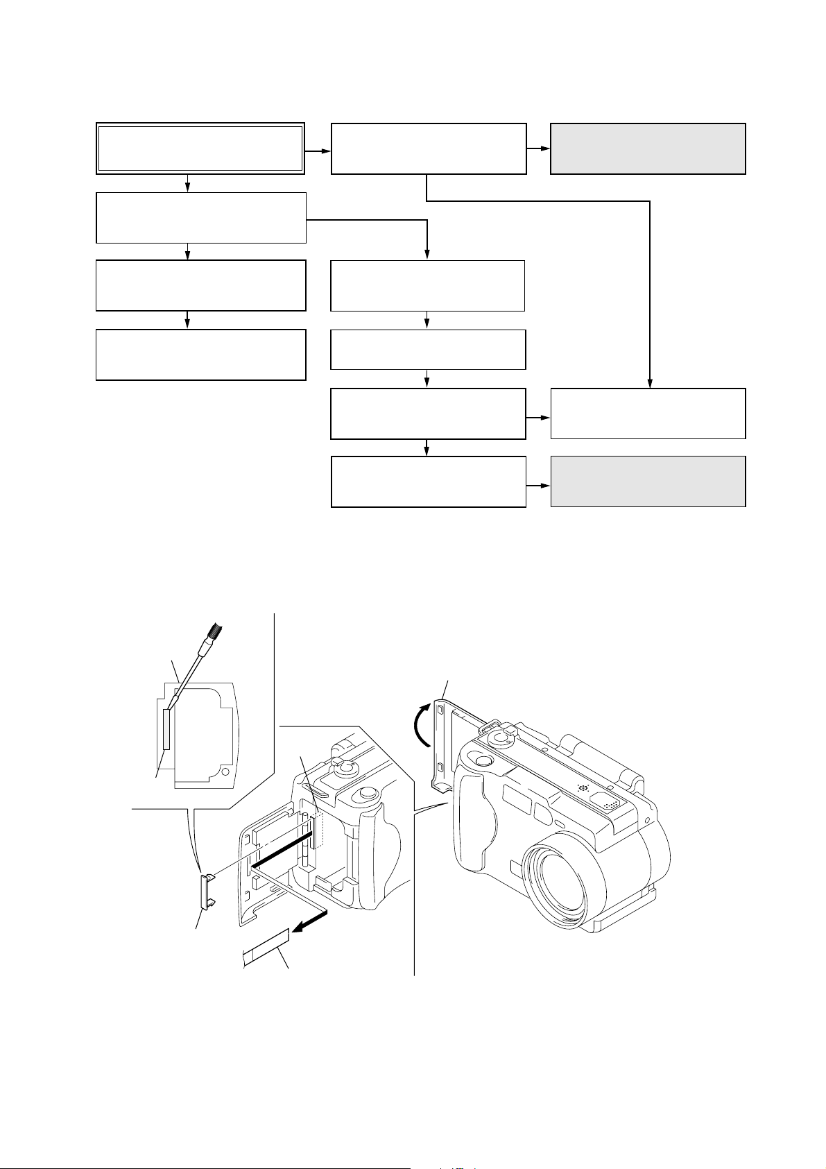
• This set can be disassembled in the order shown below.
DSC-S30/S50
SECTION 2
DISASSEMBLY
DSC-S30/S50
2-2. FRONT CABINET BLOCK
ASSEMBLY
(page 2-3)
2-3. BATTERY LID ASSEMBLY
AND CONTROL SWITCH
BLOCK (page 2-3)
2-4. FLASH UNIT AND
UPPER CABINT BLOCK
(page 2-4)
2-1. PD-127 BOARD AND
INDICATOR MODULE
(page 2-2)
2-5. MS-50 BOARD AND
BT HOLDER ASSEMBLY
(page 2-4)
2-6. LENS BLOCK ASSEMBLY
(page 2-5)
2-7. SY-58 BOARD, DD-141
BOARD AND JK-194 BOARD
(page 2-5)
2-8. CONTROL SWITCH BLOCK
AND SW-339 BOARD
(page 2-6)
SERVICE POSITION
(LCD PANEL AND PD-127 BOARD)
(page 2-2)
2-9. HINGE ASSEMBLY AND
KJ-11 BOARD
(page 2-7)
OVERALL CHECK SERVICE
POSITION
(page 2-6)
• ATTACHMENT OF CPC-9 JIG
BT holder
assembly
SY-58 board
(CN709)
CPC lid
1
CPC lid
(Note 3)
Note 1: Don’t use the 12 pin flexible board of
CPC-9 jig. It causes damage to the unit.
Note 2: The old CPC-9 jig (Parts code: J-6082-393-B)
cannot be used, because it cannot operate
the adjustment remote commander.
Note 3: In removing the CPC lid, start from
the upper side.
18
CPC-9 jig (J-6082-393-C)
(18P flexible board)
(Note 1, 2)
Open the battery lid assembly
1
18
2-1
Page 24

Note: Follow the disassembly procedure in the numerical order given.
2-1. PD-127 BOARD AND INDICATOR MODULE
1 Screw
(M2)
0 PD-127 board and
5 P cabinet
(Rear)
4 Two claws
3 Two screws
(M2)
Display block
8 Flexible board
inverter transformer
unit
qs Screw
(1.7 × 4)
(CN851)
2 Screw
(M2)
7 Flexible board
9 Two claws
qd Two screws
(M1.7)
6 Screw
(M1.7)
(CN901)
qg Indicator module
qf Cold cathode
fluorescent tube
qa Two connectors
(CN801, 802)
Note: In removing 3 two screws,
rotate the display block.
[SERVICE POSITION (LCD PANEL and PD-127 BOARD)]
Adjustment remote
commander
CPC-9 jig
(J-6082-393-C)
(Note 1, 2)
Note 1: Don't use the 12 pin flexible board of CPC-9 jig.
It causes damage to the unit.
Note 2: The old CPC-9 jit (Parts code: J-6082-393-B) cannot be used,
because it cannot operate the adjustment remote commander.
Inverter
transformer unit
Cold cathode
fluorescent tube
PD-127 board
Indicator module
AC power
adaptor
AC IN
2-2
Page 25
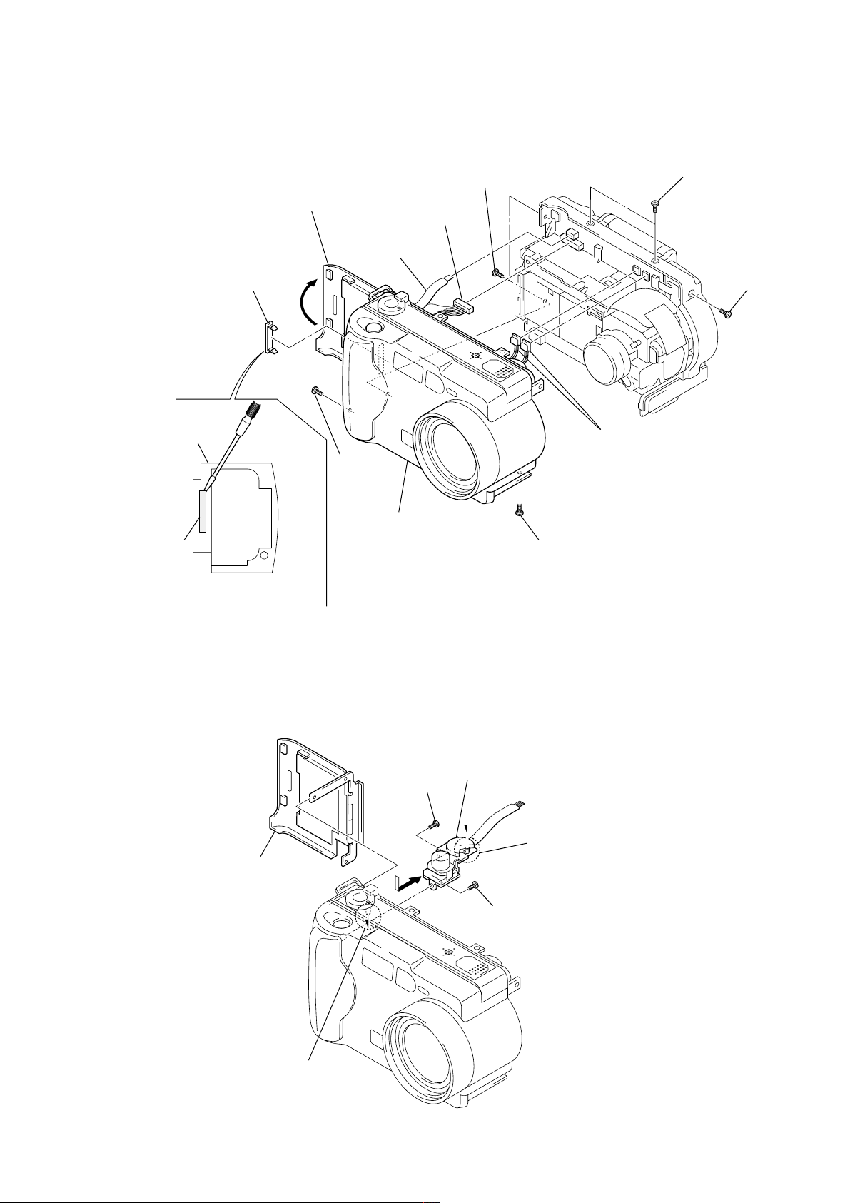
2-2. FRONT CABINET BLOCK ASSEMBLY
BT holder
assembly
CPC lid
qa CPC lid
1 Open the battery lid
assembly.
8 Flexible board
(CN707)
2 Screw
(2 × 4)
7 Front cabinet
9 Connector
(CN706)
block assembly
6 Two screws
(2 × 4)
5 Two screws
(2 × 4)
4 Screw
(2 × 4)
0 Two connectors
(CN710, 712) (S50)
0 Connector
(CN712) (S30)
3 Screw
(2 × 4)
Note: In removing the CPC lid,
start from the upper side.
2-3. BATTERY LID ASSEMBLY AND CONTROL SWITCH BLOCK
4 Remove the control switch block
(Mode SW) in the direction
of arrow A.
Note: In mounting the control
switch block (Mode SW),
align the mode SW konb
with the sleeve knob.
2 Screw
(1.7 × 4)
1 Battery lid
assembly
3 Screw
(1.7 × 4)
A
Sleeve
2-3
Page 26
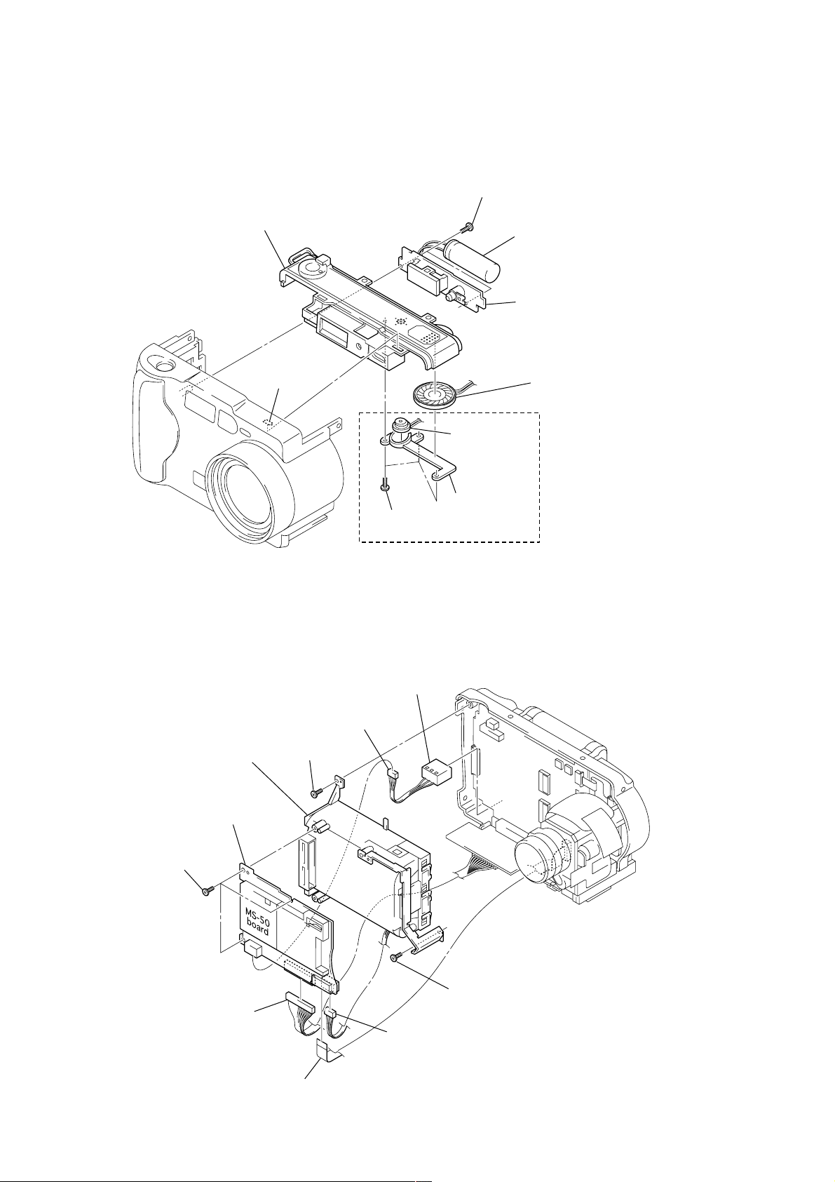
2-4. FLASH UNIT AND UPPER CABINET BLOCK
1 Two screws
(1.7 × 4)
3 Upper cabinet block
2 Claw
5 Three screws
(1.7 × 4)
2-5. MS-50 BOARD AND BT HOLDER ASSEMBLY
Capacitor
4 Flash unit
Note: Do not touch the capacitor
terminals. You could get
an electric shock.
8 Speaker (S50)
5 Buzzer (S30)
7 Microphone
unit
6 MISP holder
(S50)
9 BT holder
4 MS-50 board
3 Three screws
(1.7 × 4)
5 Connector
(CN005)
assembly
0 DC-IN
connector
1 Connector
(CN001)
8 Screw
(1.7 × 4)
7 Screw
(1.7 × 4)
6 Connector
(CN002)
2 FP-024 flexible board
(CN003)
2-4
Page 27
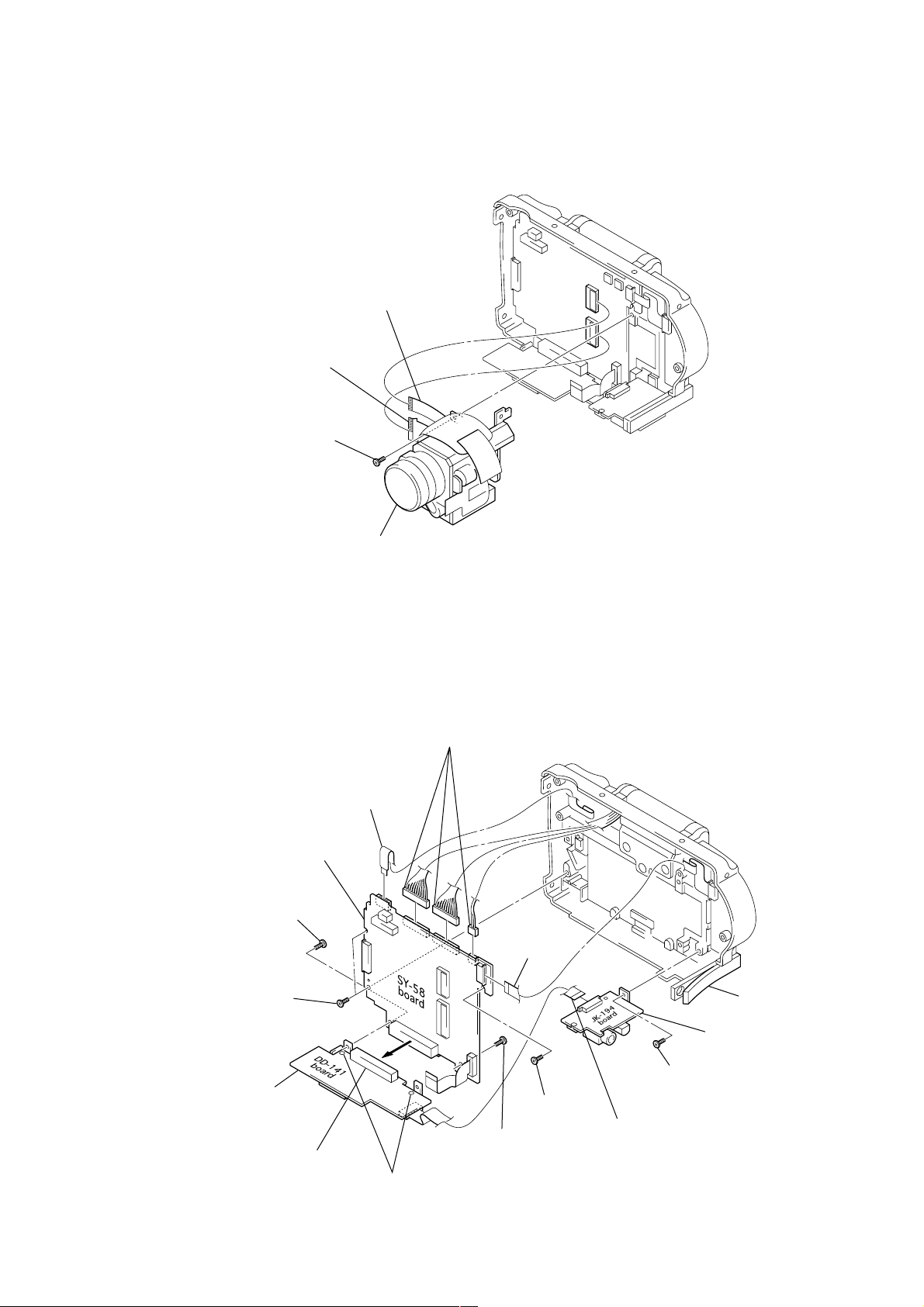
2-6. LENS BLOCK ASSEMBLY
8 Screw
(M1.7 )
4 Two screws
(1.7 × 4)
5 SY-58 board
6 Flexible board
(CN708)
7 Three connectors
(CN701, 702, 713)
2 FP-025
flexible board
(CN703)
0 Connector
(CN711)
qa DD-141 board
9 Screw
(M1.7)
1 FP-026 flexible
board (CN201)
3 Screw
(1.7 × 4)
qs Screw
(1.7 × 4)
qf JK-194 board
qd Open the JK lid.
Note: Do not remove
these two screws.
1 FP-023 flexible
board (CN101)
2 Flexible board
(CN183)
3 Screw
(1.7 × 4)
4 Lens block assembly
2-7. SY-58 BOARD, DD-141 BOARD AND JK-194 BOARD
2-5
Page 28

2-8. CONTROL SWITCH BLOCK AND SW-339 BOARD
3 Control switch block
(Zoom/power SW)
1 Two screws
(1.7 × 4)
2 Screw
(1.7 × 4)
4 Two screws
(1.7 × 4)
5 Screw
(1.7 × 4)
6 SW-339 board
[OVERALL CHECK SERVICE POSITION]
Adjustment remote
commander
CPC-9 jig
(J-6082-393-C)
(Note 1, 2)
Control switch
block (Mode SW)
SY-58
board
Note: In mounting the SW-339 board,
DC-IN connector
Memory stick
align the SW knob (S109)
with the slide knob holder.
Slide knob
holder
S109
AC power
adaptor
MS-58 board
DD-141
board
AC IN
Lens
block
assembly
Capacitor
Flash unit
(Note 3)
Note 1: Don't use the 12 pin flexible board of CPC-9 jig.
It causes damage to the unit.
Note 2: The old CPC-9 jig (Parts code: J-6082-393-B) Cannot be used,
because it cannot operate the adjustment remote commander.
Note 3: Do not touch the capacitor terminals.
You could get an electric shock.
Power SW
2-6
SW-339
board
Extention cable
(J-6082-398-A): L=200mm
(J-6082-357-A): L=100mm
Extention cable
(J-6082-423-A)
JK-194
board
Page 29
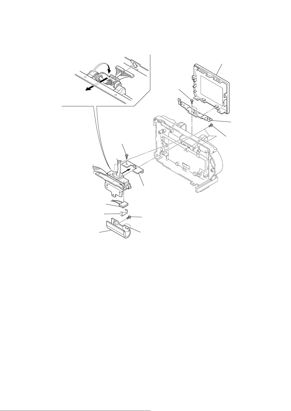
2-9. HINGE ASSEMBLY AND KJ-11 BOARD
0 Remove the hinge assembly after
turning it toward arrow
A direction.
A
6 P cabinet (Front)
7 Two screws
(M1.7)
8 BL fixed plate
qs KJ-11 board
qa KJ clip
3 Hinge cover (T)
4 Screw
(M1.7)
9 Three screws
(M1.7)
5 Hinge cover (B)
1 Screw
(M1.7)
2 Claw
2-7
Page 30
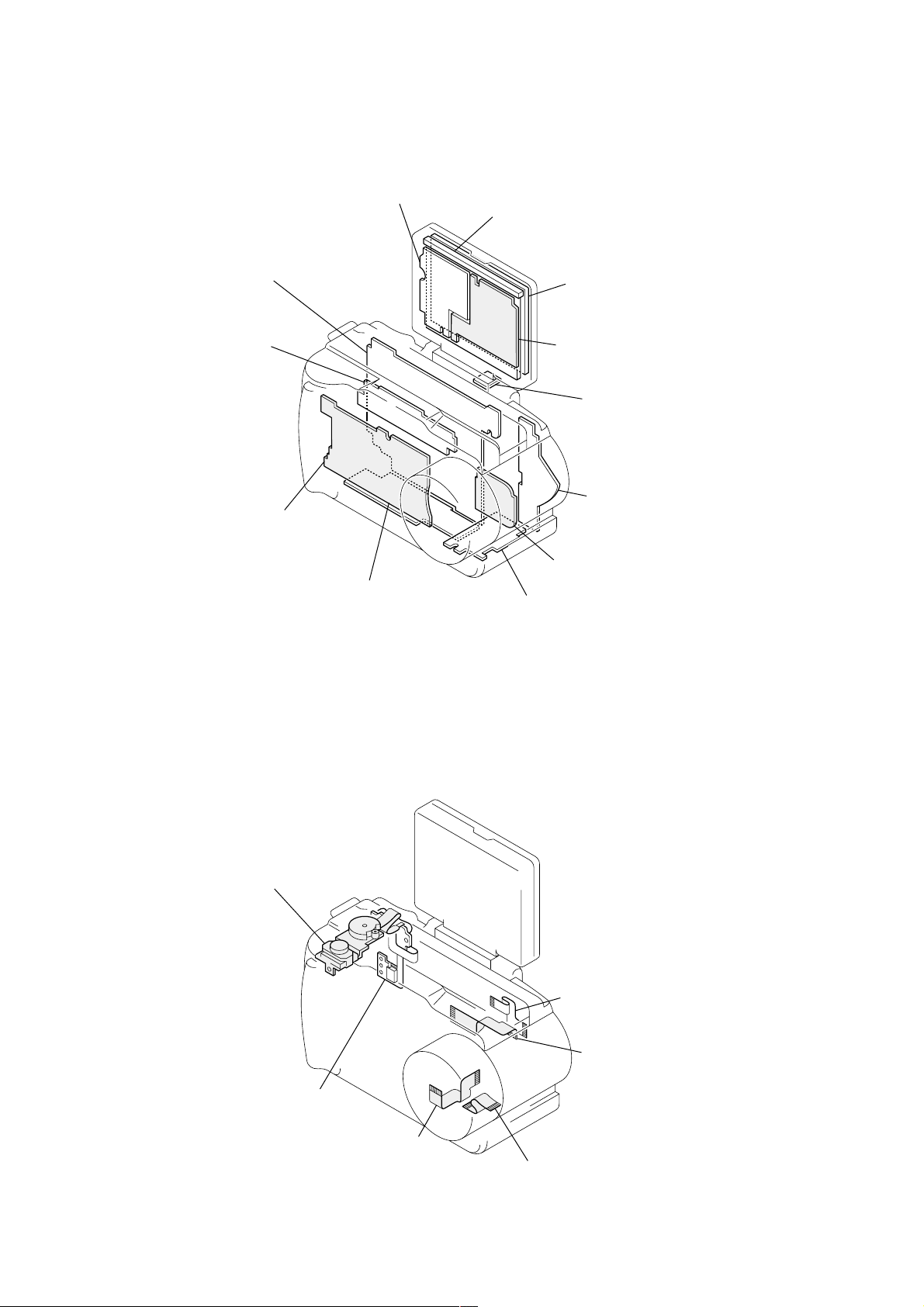
2-10. CIRCUIT BOARDS LOCATION
SY-58
AUDIO, TG/AFE, LENS DRIVE,
CAMERA, DISPLAY, MEMORY CONTROL,
( )
SH DISP, HI CONTROL
Inverter transformer
unit
Cold cathode
fluorescent
tube
Indicator module
Flash unit
MS-50
FU/MEMORY
( )
STICK
2-11. FLEXIBLE BOARDS LOCATION
PD-127
LCD DRIVE,
( )
TIMING GENERATOR
CD-262
DD-141
DC/DC CONVERTER,
( )
VIDEO, USB
(CCD IMAGER)
JK-194
(USB, A/V OUT)
KJ-11
(PANEL REVERSE)
SW-339
(SWITCH)
Control switch block
(Mode SW)
Control switch
block
(Zoom/Power SW)
FP-024
2-8
2-8 E
FP-025
FP-023
FP-026
Page 31

3-1. OVERALL BLOCK DIAGRAM
DSC-S30/S50
SECTION 3
BLOCK DIAGRAMS
LENS
METER
H
M901
FOCUS
MM
MOTOR
FOCUS MOTOR
SENSOR
M902
ZOOM
MM
MOTOR
ZOOM MOTOR
SENSOR
FLASH UNIT
FLASH
UNIT
CONTROL SWITCH BLOCK
(ZOOM POWER SWITCH)
POWER SWITCH
ZOOM SWITCH
MOVIE/STILL/PLAY
SWITCH
SHUTTER
SWITCH
CONTROL SWITCH BLOCK
(MODE SW)
SW-339 BOARD
FUNCTION
BT101
LITHIUM BATTERY
05
IRIS
KEY
DRIVE (–)
HALL (+)
CD-262 BOARD SY-58 BOARD
STB CHARGE
XPWR SW
ZOOM SW AD
MOVIE/STILL SW
XCAM/PB SW
XSHTR LOOK SW
XSHTR SW
AD1 – 3
IC301
CCD
IMAGER
(SEE PAGE 4-8) (SEE PAGE 4-17)
IC184
IC185
(SEE PAGE 4-19, 20)
IRIS
DRIVE
HALL
AMP
IC182
(SEE PAGE 4-19)
IRIS
DRIVE
FOCUS MOTOR
DRIVE
XZM RST SENS
XFC RST SENS
IC183
ZOOM MOTOR
DRIVE
(SEE PAGE 4-19)
STRB ON
PHOTO TR OUT
(SEE PAGE 4-30)
IC404
HI
CCD
OUT
HALL AD
MSHUT ON
IRIS EN
PE ENO
PE EN1
PE DIR
1A/1B
IC102
S/H, AGC,
A/D
CONVERTER
IC101
TIMING
GENERATOR
(SEE PAGE 4-17)
IC186
EVR D/A
CONVERTER
(SEE PAGE 4-20)
CNT C
HI SO, HI SI, XHI SCK
XMS IN
XCS, WE
BL ON
BL LED ON
PANEL PWM
FAST CHATGE
INIT CHARGE ON
XREST
(SEE PAGE 4-29)
BACKUP VCC
SYS DD ON
LCD DD ON
BATT XEXT
BATT SIG
(SEE PAGE 4-30)
VL 3V
DATA BUS
CAM SO, CAM SCK
CNT Y
HALL AD
IC406
EEPROM
(SEE PAGE 4-30)
IC402 IC401
RESET REG
IC405
TIMER
CLOCK
CAM SO, CAM SI, XCAM SCK
(SEE PAGE 4-29)
12
IC301
CAMERA DSP,
MEMORY CONTROL,
VIDEO DECODER
OPD, OSD,
HOST IF, SG,
JPEG, L-MODE,
RES CONTRL
(SEE PAGE 4-22)
D401
D402
DATA BUS
ADDRESS BUS
Y
R-Y
B-Y
AUSDTI
AUSDTO
Y-OUT
C-OUT
16
14
BATT UNREG
ACV UNREG
IC302
IC303
64M SDRAM
(SEE PAGE 4-23, 24)
IC252
AUDIO
AD/DA CON
(SEE PAGE 4-15) (SEE PAGE 4-16)
DATA BUS
ADDRESS BUS
16
20
16
12
HI SO, HISI, XHI SCK
CAM SO, CAM SI, XCAM SCK
CNT Y, CNT C
EXT STROB ON
FAST CHARGE
INIT CHARGE ON
SYS DD ON
LCD DD ON
BATT XEXT
BATT SIG
IC253
AUDIO
AMP
HI SO, HI SI, HI SCK
IC504
FLASH ROM
(SEE PAGE 4-28)
IC505
SDRAM
(SEE PAGE 4-28)
HALL AD
(SEE PAGE 4-27)
MC_XCSO
MC_XRD
XCKE, XCS3,
XRAS, XCAS,
XRDWR
IC507
EEPROM
PD-127 BOARD
ABCD
ABCD
(SEE PAGE 4-33)
IC501
MC CAM.
(SEE PAGE 4-26)
XMS IN
1.8VS
1.8VP
PANEL –15.3V
CAM –7.5V
CAM 15V
PANEL 13.2V
PANEL 6.5V
CAM P 5V
SP 5V
A 3.2V
PANEL 3.2V
CAM 3.2V
D 3.2V
PANEL 4.9V
A 4.9V
ACV UNREG
BATT UNREG
IC801
I/O
EXP (EVR)
BL UNIT
Y
R-Y
B-Y
Y-OUT
C-OUT
CNT Y
CNT C
USB DATA
DD-141 BOARD
IC901
LCD T. G.
(SEE PAGE 4-35)
IC802
LCD
DRIVE
(SEE PAGE 4-34)
MIC
MS-50 BOARD
(SEE PAGE 4-9, 10)
MS SCLK, MS BS, MS DIO
IC802
VIDEO
AMP
(SEE PAGE 4-46)
IC851
USB
I/F
(SEE PAGE 4-47)
IC001
DC CONTROL
(SEE PAGE 4-43)
SP
AU OUT
XMS IN
FAST CHG
INIT CHG
SYS DD
LCD DD
JK-194 BOARD
(SEE PAGE 4-40)
V OUT
V OUT
D (+)
D (–)
USB DET
CN001
DC IN
LCD901
COLOR
LCD
UNIT
CN004
10
1
+
S
–
SP901
SPEAKER
MICROPHONE
CN202
BT901
BATTERY
TERMINAL
BZ901
BUZZER
MIC901
MEMORY
STICK
S30
J201
VIDEO OUT
J201
A/V
OUT
USB
S30
S50
S50
3-1 3-2
Page 32

DSC-S30/S50
3-8. POWER BLOCK DIAGRAM 1
BT901
BATTERY
TERMINAL
MEMORY STICK
DC IN
+
S
–
TO
SY-58 BOARD
CN704
(SEE PAGE 3-15)
10
1
MS-50 BOARD
(SEE PAGE 4-9, 10 )
CN001
ACV UNREG
1
BATT/XEXT
3
2
CN002
1
BATT SIG
2
3
CN003
BATT SIG
2
BATT/XEXT
1
A4.9V
3
MS VCC
13
CN004
VCC
3
VCC
9
Q002
D002
(ACCESS LED)
R005
Q003
D006
2.1µsec
IC002 rf
1.0 Vp-p
F005
F004
F003
F002
F001
CN005
1
2
7
8
9
10
11
12
13
14
IC001
DC CONTROL
(SEE PAGE4-43)
16
RT
17
CT
FAST CHARGE
INT CHARGE ON
ST UNREG
ST UNREG
BL UNREG
UNREG3
UNREG3
UNREG2
UNREG2
BATT UNREG
18
OUTA
VCC
OUTB
SCPC
POW CONT
CTLB
CTLCD
OUTC
SCPB
SCPA
SCPD
OUTD
VREF
DD-141 BOARD
CN001
1
2
7
8
9
10
11
12
13
14
L001
46
44
24
20
21
22
40
13
8
29
39
19
SYS DD ON
L002
Q004
SWITCHING
Q001
SWITCHING
Q002
SWITCHING
Q005 – 008
REG
L006
4
1
Q003
SWITCHING
L003
SWITCHING
T001
Q034
L004
L008
Q009, 013
B+
SWITCH
D002
3
2
5
6
8
D001
L011
L012
L009
L005
Q014, 016
B+
SWITCH
EMERGENCY
Q010
SWITCHING
Q036
D003, 004
RECT
DETECT
L014
LCD DD ON
Q021, 024, 030
B–
SWITCH
Q020, 023, 026, 029
B–
SWITCH
Q019, 027, 031, 033
B+
SWITCH
Q020, 032, 025, 028
B+
SWITCH
R072
INIT CHARGE ON
L801
FAST CHARGE
SYS DD ON
LCD DD ON
ST UNREG
BU UNREG
BATT UNREG
D1.8VS
D1.8VP
PANEL –15.3V
CAM –7.5V
CAM 15V
PANEL 13.2V
PANEL 6.5V
CAM P5V
SP 5V
A3.2V
PANEL 3.2V
CAM 3.2V
D3.2V
PANEL 4.9V
A4.9V
CN852
69
71
70
68
51
53
63
65
64
41
43
42
44
62
50
52
60
58
55
57
59
61
37
39
54
46
48
45
47
49
56
38
40
TO
SY-58 BOARD
CN711
(SEE PAGE 3-17)
IC851
USB IF
(SEE PAGE 4-47)
05
3-15 3-16
A3.2V
Q806, 807
IC802
VIDEO AMP
(SEE PAGE4-46)
Page 33

3-9. POWER BLOCK DIAGRAM 2
DSC-S30/S50
TO
DD-141 BOARD
CN852
(SEE PAGE 3-16)
SY-58 BOARD
CN711
FAST CHARGE
12
INIT CHARGE ON
10
SYS DD ON
11
LCD DD ON
13
ST UNREG
28
30
BL UNREG
16
18
BATT UNREG
17
D1.8VS
38
40
D1.8VP
39
41
PANEL –15V
19
CAM –7.5V
31
CAM 15V
29
PANEL 13.2V
21
PANEL 6.5V
23
CAM P5V
24
26
CAM SP5V
20
22
A3.2V
42
44
PANEL 3.2V
27
CAM 3.2V
33
35
30
D3.2V
32
34
D402D401
ACV UNREG
BL UNREG
100
27
29
47
D411
(BATT CHARGE)
IC401
REG
(SEE PAGE 4-29)
D1.8VP
D1.8VS
(SEE PAGE 4-30)
FAST CHARGE
INIT CHARGE
SYS DD ON
LCD DD ON
94
32
CAM 15V
CAM –7.5V
IC404
HI
BATT/XEXT
BATT SI
BATT SG
POWER LEDCHARGE LED
60
BACK UP VDD
Q253
20
48
49
D412
(POWER LED)
Q409
BLOCK
D3.2V
A4.9V
D3.2V
D3.2V
IF
(SEE PAGE 4-30)
S50
CONVERTER
(SEE PAGE 4-15)
Q701, 702
MS ON
(IC501)
IC406
EEPROM
IC252
DA/AD
A3.2V
D1.8VS
CN704
BATT/XEXT
BATT SIG
MS VCC
A4.9V
IC402
RESET
(SEE PAGE 4-29)
IC253
AUDIO AMP
(SEE PAGE 4-16)
L254
14
13
(SEE PAGE 3-13)
2
12
TO
MS-54 BOARD
CN003
CPC
(FOR CHECK)
10 18
CN709
CAMERA DSP, V ENCODER,
MEMORY CONTROL
(SEE PAGE 4-22)
CAM P5V
L303
D1.8VP
IC301
FB301
BACK UP VDD
A4.9V
ST UNREG
CA15V
CAM –7.5V
64M SDRAM
(SEE PAGE 4-23)
FB304
FB302
CAM 3.2V
D3.2V
L185 L181
IC302
ST UNREG
A4.9V
CN706
8
4
IC303
64M SDRAM
(SEE PAGE 4-24)
(SEE PAGE 4-17)
L183
FLASH
UNIT
D410
CAM DD ON
IC101
TIMING
GENERATOR
R485
TIMER CLOCK
(SEE PAGE 4-30)
IC405
A/D CONVERTER
(SEE PAGE 4-17)
Q189, 190
Q103, 105
SWITCHING
IC102
Q182
XLENS RST LED
DAC ENB
Q102
Q104
1
CN703
D3.2V D3.2V
VL3V
761
CAM 15VCAM 15V
CAM –7.5VCAM –7.5V
F SENS VCC
Z SENS VCC
CN708
D3.2V
11418
CN183
7
19
4
SW-339 BOARD
D102
LED
CN101
2
BT101
(3V)
CD-262 BOARD
CN301CN101
5
IC301
CCD
IMAGER
(SEE PAGE 4-8)
LENS UNIT
(SEE PAGE 4-19)
VCC
VCC
CONTROL SWITCH
BLOCK
(ZOOM/POWER SW)
(SEE PAGE 4-29)
D3.2V
IC507
EEPROM
(SEE PAGE 4-27)
IC504
FLASH ROM
(SEE PAGE 4-28)
IC505
SDRAM
(SEE PAGE 4-27)
IC501
MC CAM
(SEE PAGE 4-26)
IC503
CLOCK
(SEE PAGE 4-26)
IC182
SHUTTER/FOCUS
MOTOR DRIVE
(SEE PAGE 4-19)
IC183
ZOOM MOTOR
DRIVE
(SEE PAGE 4-19)
IC184
IRIS
DRIVE
(SEE PAGE 4-19)
IC185
HALL
AMP
(SEE PAGE 4-19)
IC186
EVR
(SEE PAGE 4-20)
CN707
D3.2V
3
D3.2V
CONTROL SWITCH
CN702
BL UNREG
PANEL –15V
PANEL 13.2V
PANEL 6.5V
PANEL 4.9V
25
A4.9V
41
43
05
PANEL 3.2V
PANEL 4.9V
CN701
3
PANEL –15V
1
PANEL 13.2V
2
PANEL 6.5V
3
PANEL 3.2V
5
6
4
D3.2V
PANEL 4.9V
3
1
2
3
5
6
4
CN801
CN802
L801
BL UNIT
BL UNREG
IC801
I/O EXP
(SEE PAGE 4-33)
L903
PD-127 BOARD
IC802
LCD DRIVE
(SEE PAGE 4-34)
PANEL –15V
PANEL 13.2V
PANEL 4.9V
IC901
TIMING
GENERATOR
(SEE PAGE 4-35)
IC902
COM AMP
(SEE PAGE 4-35)
VSS
VGH
VSH
VSH
CN901
LCD901
9
1
12
2
COLOR
LCD
UNIT
BLOCK
(MODE SW)
(SEE PAGE 4-29)
3-17 3-18 E
Page 34

SECTION 4
21321321
3
345
21
123
654
EB
C
31
5
5246
123
54
Transistor Diode
PRINTED WIRING BOARDS AND SCHEMATIC DIAGRAMS
THIS NOTE IS COMMON FOR WIRING BOARDS AND SCHEMATIC DIAGRAMS
(In addition to this, the necessary note is printed in each block)
DSC-S30/S50
(For printed wiring boards)
• b: Pattern from the side which enables seeing.
(The other layers’ patterns are not indicated)
• Through hole is omitted.
• Circled numbers refer to waveforms.
• There are few cases that the part printed on diagram
isn’t mounted in this model.
• Chip parts.
(For schematic diagrams)
• All capacitors are in µF unless otherwise noted. pF : µ
µF. 50 V or less are not indicated e xcept for electrolytics
and tantalums.
• Chip resistors are 1/10 W unless otherwise noted.
kΩ=1000 Ω, MΩ=1000 kΩ.
• Caution when replacing chip parts.
New parts must be attached after removal of chip.
Be careful not to heat the minus side of tantalum
capacitor, Because it is damaged by the heat.
• Some chip part will be indicated as follows.
Example C541 L452
22U 10UH
TA A 2520
(Measuring conditions voltage and waveform)
• Voltages and waveforms are measured between the
measurement points and ground when camera shoots
color bar chart of pattern box. The y are reference v alues
and reference waveforms. *
(VOM of DC 10 MΩ input impedance is used)
• V oltage values change depending upon input impedance
of VOM used.)
1. Connection
Pattern box
L
Front of the lens
L=About 90cm
Kinds of capacitor
Temperature characteristics
External dimensions (mm)
• Constants of resistors, capacitors, ICs and etc with XX
indicate that they are not used.
In such cases, the unused circuits may be indicated.
• Parts with ★ differ according to the model/destination.
Refer to the mount table for each function.
• All variable and adjustable resistors have characteristic
curve B, unless otherwise noted.
• Signal name
XEDIT→ EDIT PB/XREC → PB/REC
• 2: non flammable resistor
• 1: fusible resistor
• C: panel designation
• A: B+ Line *
• B: B– Line *
• J : IN/OUT direction of (+,–) B LINE. *
• C: adjustment for repair. *
• Circled numbers refer to waveforms. *
* Indicated by the color red.
Note : The components identified by mark 0 or
dotted line with mark 0 are critical for safety.
Replace only with part number specified.
Note : Les composants identifiés par une marque
0 sont critiques pour la sécurité.
Ne les remplacer que par une pièce portant
le numéro spécifie.
2. Adjust the distance so that the output waveform of Fig.
a and the Fig. b can be obtain.
H
Yellow
Cyan
White
Magenta
Green
AABBA=B
Fig. a (Video output terminal output waveform)
Cyan
White
Green
Yellow
Fig.b (Picture on monitor TV)
Magenta
Red
Blue
Red
Blue
Color bar chart
picture frame
Monitor TV
picture frame
When indicating parts by reference number, please
include the board name.
4-1
Page 35

DSC-S30/S50
4-1. FRAME SCHEMATIC DIAGRAMS
FRAME SCHEMATIC DIAGRAM (1/2)
1
27
4
65
9
11 12 15 16
1410 1383
17
18
A
CONTROL
18P
CN101
POWER_SW
6
ZOOM_SW_AD
6P
CN708
SWITCH
BLOCK
S901
POWER
S902
(ZOOM)
NC
D_3.2V
TW
12345
NC
GND
XPER_SW
LCD901
PANEL UNIT
(COLOR LCD)
B
9VSS
8MO2
7MO1
6GPCK
5SPS
4CLS
3VCC
2VSH
24CLD
23SPD
22CTR
21EX3
20EX2
19VB12
18RES
17TST
16VR
15VG
14VB
13GND
12VSH
11COM
10VGL
20 N.C
19 BL_HIGH
18 BL_HIGH
17 N.C
16 N.C
15 N.C
14 N.C
13 N.C
12 N.C
11 N.C
10 N.C
9 N.C
8 N.C
7 N.C
6 N.C
5 LED
4 LED_GND
3 BL_LOW
2 BL_LOW
1 UNREG_GND
24P
CN901
CN851
20P
PD-127 BOARD
BL UNIT
C
ND901
D
E
BACK LIGHT
F
1VGH
CN802
PANEL_-15.3V
PANEL_13.2V
PANEL_6.5V
PANEL_4.9V
PANEL_3.2V
D_3.2V
PANEL_COM
HSY
VG
REG_GND
REG_GND
PANEL_Y
PANEL_R-Y
PANEL_B-Y
CN801
BL_GND
BL_GND
BL_UNREG
BL_ON
BL_LED_ON
PANEL_PWM
XHI_SCK
HI_SO
XCS_PANEL_D/A
PANEL_V
HDO
REG_GND
14P
12P
1
2
3
4
5
6
7
8
9
10
11
12
13
14
1
2
3
4
5
6
7
8
9
10
11
12
1
2
3
4
5
6
7
8
9
10
11
YP-052 HARNESSYP-051 HARNESS
12
13
14
1
2
3
4
5
6
7
8
9
10
11
12
XCS_PANEL_D/A
PANEL_-15.3V
PANEL_13.2V
PANEL_6.5V
PANEL_4.9V
PANEL_3.2V
PANEL_COM
REG_GND
REG_GND
PANEL_Y
PANEL_R-Y
PANEL_B-Y
BL_UNREG
BL_LED_ON
PANEL_PWM
XHI_SCK
PANEL_V
REG_GND
CN701
D_3.2V
CN702
BL_GND
BL_GND
BL_ON
HI_SO
14P
HSY
VG
12P
HDO
123456789
N.C
N.C
N.C
18P
CN709
CPC
(FOR CHECK) ZOOM/
101112131415161718
VG
REG_GND
XCPC_IN
N.C
HSY
PANEL_COM
UNREG
LANC_IN
N.C
LANC_OUT
RF7
S50 S30
MICROPHONE
TXD
VDD
RXD
RESET
MIC901 SP901
1MIC SIG
2MIC GND
2P
2P
CN712
CN710
SPEAKER
BZ901
1SP +
2SP -
1
2SP -
SP +
2P
CN712
SY-58 BOARD (1/2)
26P
CN183
10P
CN706
9
10
STROB_ON
XSTB_FULL
FLASH UNIT
6
7
8
TALLY
UNREG
PHOTO_TR_OUT
4
5
A_4.9V
UNREG_GND
2
3
POP_UP_ON
STRB_PHOTO_ON
1
STB_CHARGE
CONTROL
SWITCH
BLOCK
(MODE_SW)
S903
MOVIE STILL PLAY
S904
(SHUTTER)
6
GND
D_3.2V
XSHTR_SW
6P
CN707
XCAM/PB_SW
XSHTR_LOCK_SW
12345
MOVIE/XSTILL_SW
G
V1A
VSHT
VSHT
VSUB_CONT
V4
V3B
GND
V1B
V2
V3A
101112131415161718
987654321
V2
V1B
V3A
V3B
V1A
GND
GNDH1CAM_15V
GND
CCD_OUT
123456789
GND
GND
CCD_OUT
CAM_15V
CAM_-7.5V
GND/TEMP
RG
IB
05
IA
IA
IB
TEMP_COM (GND)
TEMP_OUT
Z_SENS_RST
Z_SENS_VCC
ZOOM_A
Z_SENS_GND
ZOOM_B
ZOOM_B
ZOOM_A
DRIVE-
DRIVE+
BIAS+
HALL+
1011121314151617181920212223242526
BIAS-
HALL-
F_SENS_VCC
F_SENS_RST
F_SENS_GND
FOCUS_A
FOCUS_B
FOCUS_B
FOCUS_A
123456789
FP-021 FLEXIBLE BOARD
H
IC301
LENS UNIT
M901
I
M902
ZOOM MOTORFOCUS MOTOR
CCD IMAGER
MM
H2V4VSUB_CONT
FP-023 FLEXIBLE BOARD
181716151413121110
H1
H2
RG
GND/TEMP
CAM_-7.5V
18P
CN301
CD-262 BOARD
FRAME (1/2)
4-3 4-4
Page 36

FRAME SCHEMATIC DIAGRAM (2/2)
DSC-S30/S50
1
27
4
65
83
9
11 12 15 16 19
1410 13
17
18
A
S101
(CONTROL BUTTON)
B
S104
PROGRAM AE
S102
DISPLAY
S103
(FLASH)
C
D
E
7P
KEY_AD2
KEY_AD1
REG_GND
KEY_AD3
CN101
FP-025
FLEXIBLE
BOARD
1234567
7P
KEY_AD2
KEY_AD1
KEY_AD3
REG_GND
CN703
XCHG_LED
D_3.2V
D_3.2V
XCHG_LED
VL_3V
1234567
VL_3V
S105
PROGRAM AE/
VOLUME +
S107
FOCUS
S108
PROGRAM AE/
VOLUME -
S109
LCD
BACK LIGHT
S106
PANEL
UP/DOWN
D102
(FLASH)
BT101
(LITHIUM BATTERY)
S110
PANEL
ON/OFF
SW-339 BOARD
JK-194 BOARD
J201
A/V OUT
DSC-S50
VIDEO
OUT
DSC-S30
4P
CN202
CN201
16P
REG_GND
1
A_OUT
2
REG_GND
3
V_OUT
4
AV_JACK_IN
5
N.C.
6
N.C.
7
N.C.
8
N.C.
9
N.C.
10
N.C.
11
USB_DET
12
REG_GND
13
D+
14
D-
15
REG_GND
16
1 VCC
2D-
3D+
4 GND
USB
F
14P
CN003
BATT/XEXT
10PCN004
G
MEMORY STICK
H
I
J
DC IN 3P
BT901
BATTERY TERMINAL
K
L
1 VSS
2BS
3 VCC
4DIO
5N.C
6INT
7N.C
110
8 SCLK
9 VCC
10 VSS
D002
ACCESS LED(RED)
MS-50 BOARD
3PCN001
1
ACV_UNREG
ACV_GND
2
3 BATT/XEXT
CN002
3P
1 BATT_UNREG
2 BATT_SIG
S
3 BATT_GND
05
FAST_CHARGE
INIT_CHARGE_ON
UNREG5(ST_UNREG)
UNREG5(ST_UNREG)
UNREG4(BL_UNREG/ACV)
UNREG3(TRANS/A4.9)
UNREG3(TRANS/A4.9)
UNREG2(D3.2/1.8V)
UNREG2(D3.2/1.8V)
UNREG1(BATT_UNREG)
BATT_SIG
ACCESS_LED
REG_GND
MS_DIO
GND_GARD
XMS_IN
GND_GARD
MS_SCLK
GND_GARD
MS_VCC
REG_GND
CN005
REG_GND
REG_GND
REG_GND
REG_GND
A_4.9V
MS_BS
14P
1
2
3
4
5
6
7
8
9
10
11
12
13
14
1
2
3
4
5
6
7
8
9
10
11
12
13
14
FP-024
FLEXIBLE
BOARD
YP-052 HARNESS
BATT/XEXT
14
BATT_SIG
13
A_4.9V
12
ACCESS_LED
11
REG_GND
10
MS_BS
9
MS_DIO
8
GND_GARD
7
XMS_IN
6
GND_GARD
5
4
MS_SCLK
3
GND_GARD
2
MS_VCC
REG_GND
1
CN001
FAST_CHARGE
1
INIT_CHARGE_ON
2
REG_GND
3
REG_GND
4
REG_GND
5
REG_GND
6
UNREG5(ST_UNREG)
7
UNREG5(ST_UNREG)
8
UNREG4(BL_UNREG/ACV)
9
UNREG3(TRANS/A4.9)
10
11
UNREG3(TRANS/A4.9)
UNREG2(D3.2/1.8V)
12
UNREG2(D3.2/1.8V)
13
UNREG1(BATT_UNREG)
14
14PCN704
72
747678
80
CNT_Y
C_OUT
AU_OUT
AU_GND
REG_GND
REG_GND
80P
REG_GND
REG_GND
REG_GND
USB_D+OUT
CN711
737577
79
246
8
REG_GND
REG_GND
14P
REG_GND
CN852 80P
REG_GND
13579
REG_GND
AU_OUT
USB_D+OUT
AU_GND
Y_OUT
REG_GND
XAU_LINE_MUTE
USB_TXENL
USB_D-OUT
REG_GND
71
1012141618202224262830323436384042444648505254565860626466687072747678
REG_GND
USB_D-OUT
USB_TXENL
REG_GND
C_OUT
XAU_LINE_MUTE
1113151719212325272931333537394143454749515355575961636567697173757779
REG_GND
USB_XVDATA
USB_XVDATA
REG_GND
REG_GND
REG_GND
Y_OUT
REG_GND
USB_D+IN
USB_D+IN
REG_GND
USB_D-IN
USB_D-IN
CNT_Y
REG_GND
REG_GND
REG_GND
REG_GND
SY-58 BOARD (2/2)
44
46485052545658606264666870
N.C.
N.C.
CNT_C
VOUT_ON
USB_D+PULLUP
USB_SUSPND
REG_GND
EXT_STRB_ON
LANC_JACK_IN
USB_DET
A_3.2V
REG_GND
AV_JACK_IN
A_4.9V
45474951535557596163656769
BOARD TO BOARD CONNECTOR
A_4.9V
USB_DET
EXT_STRB_ON
LANC_JACK_IN
USB_D+PULLUP
N.C.
VOUT_ON
REG_GND
N.C.
AV_JACK_IN
REG_GND
A_3.2V
USB_SUSPND
CNT_C
DD-141 BOARD
A_3.2V
A_4.9V
A_4.9V
A_3.2V
D_1.8VS
D_1.8VP
D_1.8VP
D_1.8VS
D_1.8VS
D_1.8VP
D_1.8VP
D_1.8VS
D_3.2V
CAM_3.2V
CAM_3.2V
D_3.2V
D_3.2V
D_3.2V
CAM_3.2V
CAM_-7.5V
CAM_3.2V
CAM_-7.5V
D_3.2V
D_3.2V
ST_UNREG
ST_UNREG
CAM_15V
PANEL_3.2V
272931333537394143
PANEL_3.2V
CAM_15V
ST_UNREG
ST_UNREG
CAM_P_5V
PANEL_4.9V
25
PANEL_4.9V
CAM_P_5V
SP_5V
CAM_P_5V
PANEL_13.2V
PANEL_6.5V
23
PANEL_6.5V
PANEL_13.2V
SP_5V
CAM_P_5V
18202224262830323436384042
SP_5V
BL_UNREG
BATT_UNREG
PANEL_-15V
171921
PANEL_-15V
BATT_UNREG
BL_UNREG
SP_5V
16
N.C.
BL_UNREG
N.C.
LCD_DD_ON
N.C.
LCD_DD_ON
N.C.
BL_UNREG
101214
FAST_CHARGE
INIT_CHARGE_ON
SYS_DD_ON
REG_GND
111315
REG_GND
SYS_DD_ON
FAST_CHARGE
INIT_CHARGE_ON
8
LANC_DC
XLANC_PWR_ON
LANC_SIG
REG_GND
REG_GND
LANC_SIG
LANC_DC
XLANC_PWR_ON
REG_GND
REG_GND
REG_GND
REG_GND
246
REG_GND
REG_GND
13579
80
REG_GND
REG_GND
D411
(BATT CHARGE)
D412
(POWER)
AV_JACK_IN
REG_GND
REG_GND
USB_DET
V_OUT
REG_GND
A_OUT
REG_GND
KJ-11 BOARD
S301
CN713
16PCN851
16
D-
15
D+
14
13
12
N.C.
11
N.C.
10
N.C.
9
N.C.
8
7
N.C.
N.C.
6
5
4
3
2
1
SK-100
2P
HARNESS
1KEY_AD0
2REG_GND
FP-026 FLEXIBLE BOARD
PANEL
REVERSE
4-5 4-6
FRAME (2/2)
Page 37

DSC-S30/S50
4-2. PRINTED WIRING BOARDS AND SCHEMATIC DIAGRAMS
CD-262 (CCD IMAGER) PRINTED WIRING BOARD AND SCHEMATIC DIAGRAM
– Ref. No.: CD-262 board; 2,000 series –
• See page 4-49 for waveforms.
• For Printed Wiring Board.
• CD-262 board is four-layer print board. How ever , the patterns
of layers 2 to 3 have not been included in the diagram.
• There are few cases that the part isn't mounted in this model
is printed on this diagram.
• Chip transistor
C
EB
1
A
B
18PCN301
RG
GND/TEMP
26
SY-58 BOARD (2/8)
CN101
(THROUGH THE
FP-023 FLEXIBLE)
(SEE PAGE 4-17)
H2
CAM_-7.5V
VSHTH1V3A
VSUB_CONT
V4
V3B
101112131415161718
GND
GND
CCD_OUT
GND
V1A
V1B
V2
CAM_15V
123456789
49735
CD-262 BOARD
CCD IMAGER
-REF.NO.:2,000 SERIESXX MARK:NO MOUNT
NO MARK:STILL/PB MODE
S:STILL MODE
P:PB MODE
8
C
Q302
2SC4178-F13F14-T1
L301
D
E
F
G
05
100uH
S-1.7/P0
S-1.7/P0
S-0.2/P0
1V42
3
S2.7/P0
S2/P0
6.8k
2.2k
0.1
UN9213J-(K8).SO
V3A3V3B
S2.6/P0
C305
0.1u
16V
S9/P0
R304
:S30
:S50
S-0.2/P0
4V25
45
S-7.4/P0 S8.4/P0
Q301
S-1.7/P0
IC301
CCD IMAGER
IC301
ICX202BQ-13
:S30
ICX284AQ-13
:S50
*R302,303
D301
MA111-(K8).S0
25V1uC311
FB301
C302
C303
22u
0.01u
16V
C301
10u
20V
16V
R308
100k
1
33
:S30
15
:S50
2
R302
*
R303
*
R301
47
C304
0.1u
50V
S-0.2/P0
V1A6V1B
S8.2/P0
R309
C307
0.1u
16V
S11.4/P0
7
8
GND
VOUT
VDD10GND11VSHT12CSUB13VL14RG15H116H2
9
S14.8/P0
*
R305
*
C312
2200p
*R305
1M
:S30
220k
:S50
C306
0.1u
16V
*R309
47
:S30
22
:S50
S14.8/P0
R307
C309
C308
0.1u
16V
0
10p
C310
XX
S10.5/P0
R306
3300
SIGNAL PATH
VIDEO
SIGNAL
Y/CHROMA
REC
CCD IMAGER
CD-262
Precautions for Replacement of CCD Imager
• The CD-262 board mounted as a repair part is not equipped
with a CCD imager.
When replacing this board, remove the CCD imager from the
old one and mount it onto the new one.
• If the CCD imager has been replaced, carry out all the
adjustments for the camera section.
• As the CCD imager may be damaged by static electricity from
its structure, handle it carefully like for the MOS IC.
In addition, ensure that the receiver is not covered with dusts
nor exposed to strong light.
4-7 4-8
Page 38

MS-50 (FU, MEMORY STICK) PRINTED WIRING BOARD AND SHEMATIC DIAGRAM
– Ref. No.: MS-50 board; 2,000 series –
DSC-S30/S50
• For Printed Wiring Board.
• There are few cases that the part isn't mounted in this model
is printed on this diagram.
• Chip transistor
C
EB
1
MS-50 BOARD
A
FU/MEMORY STICK (FU/MS BLOCK)
-REF.NO.:2,000 SERIESXX MARK:NO MOUNT
NO MARK:STILL/PB MODE
CN001
BT901
BATTERY
TERMINAL
S
SY-58 BOARD (6/8)
CN704
(THROUGH THE
FP-024 FLEXIBLE)
(SEE PAGE 4-25)
DC IN
CN002
CN003
B
C
D
E
F
G
H
3P
LND001
FLAME_GND
05
3P
14P
BATT/XEXT
BATT_SIG
A_4.9V
ACCESS_LED
REG_GND
MS_BS
MS_DIO
GND_GARD
XMS_IN
GND_GARD
MS_SCLK
GND_GARD
MS_VCC
REG_GND
38131056
1ACV_UNREG
2ACV_GND
3BATT/XEXT
FB002
R008
XX
C002
C001
XX
XX
1BATT_UNREG
2BATT_SIG
FB001
3BATT_GND
1
2
3
4
5
6
7
8
9
10
11
12
13
14
R001
1k
LF001
R009
0
4
D001
MA8082-(K8).S0
D002
CL-270HR-C-TS
(ACCESS LED(RED))
C006
0.1u
D003
MA8082-(K8).S0
R002
1k
C003
0.1u
Q002,003
BATTERY
CHARGE/DISCHARGE
SI4963DY-T1
8
R003
470k
D005
MA8120-TX
C004
0.022u
7.8
SSM3K03FE(TPL3)
CN004
1
2
3
5
6
7
8
9
10
C007
2200p
Q002
7.8
1
4
0
Q001
SWITCHING
MEMORY STICK
10P
VSS
BS
VCC
DIO4
N.C
INT
N.C
SCLK
VCC
VSS
2
7
8.3
8
8
53
6
7.8
R004
1M
1608
8.2
8.2
R005
10
3216
2SB1122-ST-TD
D006
1SS357-TPH3
UN9213J-(K8).SO
SWITCHING
110
72
R006
1k
Q003
7.6
R007
6800
3.2
0
Q004
F001
1.4A/32V
9
1.4A/32V
F005
1.4A/32V
F004
F003
1.4A/32V
F002
1.4A/32V
C005
XX
11
CN005
FAST_CHARGE
1
INIT_CHARGE_ON
2
REG_GND
3
REG_GND
4
REG_GND
5
REG_GND
6
UNREG5(ST_UNREG)
7
UNREG5(ST_UNREG)
8
UNREG4(BL_UNREG/ACV)
9
UNREG3(TRANS/A4.9)
10
UNREG3(TRANS/A4.9)
11
UNREG2(D3.2/1.8V)
12
UNREG2(D3.2/1.8V)
13
UNREG1(BATT_UNREG)
14
12
14P
DD-141 BOARD (1/3)
CN001
(THROUGH THE
YP-052 HARNESS)
(SEE PAGE 4-43)
The components identified by mark 0 or dotted
line with mark 0 are critical for safety.
Replace only with part number specified.
Les composants identifiés par une marque 0 sont
critiques pour la sécurité. Ne les remplacer que
par une piéce portant le numéro spécifié.
4-9 4-10
FU/MEMORY STICK
MS-50
Page 39

DSC-S30/S50
PD-127 (TG, LCD) PRINTED WIRING BOARD
– Ref. No.: PD-127 board; 2,000 series –
• For Printed Wiring Board.
• PD-127 board is four-layer print board. Howe ver , the patterns
of layers 2 to 3 hav e not been included in the diagram.
• There are few cases that the part isn't mounted in this model
is printed on this diagram.
• Chip transistor
C
EB
TG, LCD
PD-127
4-31 4-32
Page 40

PD-127 (LCD DRIVE) SCHEMATIC DIAGRAM • See page 4-49 for waveforms.
DSC-S30/S50
1
A
PD-127 BOARD (1/2)
3 8 10 13
4
65
ND901 BACK LIGHT
7
9
14
15 1611 122
LCD DRIVE (RGB BLOCK)
-REF.NO.:2,000 SERIESXX MARK:NO MOUNT
NO MARK:STILL/PB MODE
1UNREG_GND
2BL_LOW
3BL_LOW
4LED_GND
5LED
6N.C
7N.C
8N.C
9N.C
10N.C
11N.C
12N.C
13N.C
14N.C
15N.C
16
17N.C
18BL_HIGH
19BL_HIGH
P_MUTE
BRT_TST
BL_LEVEL
V-COM
COM_ADJ
RGB_AMP
BRT_B
BRT_R
COLOR
BRIGHT
CONT
C803
C804
C805
20N.C
AMP
FRPT
FRPV
BRT_B
COM_ADJ
R813
R812
R808
22k
R809
12k
C807
47u
3.1
12
3.1
11
10
1.8
9
1.2
VCO
8
COM_ADJ
0.9
7
2.3
6
2
5
1.8
4
2.3
3
1.1
2
1.9
1
0.01u
0.01u
0.01u
6.3V
V-COM
VCO
AMP
BRT_B
BRT_R
COLOR
C806
0.1u
R803
C808
0.1u
3.2
1.9
COM-O
0
R805
0
INB
1
5
VCC
2
INA
3
4
OUT
GND
IC803
XX
2
3.1
4.9
47k
COM_BLK
37
XTEST
38
BRIGHT
39
CONTRAST
40
COM_OUT
41
SUB_CON_B
42
SUB_CON_R
43
VCC1
44
OSD_B
45
OSD_G
46
OSD_R
47
BLACK_IN
48
R806
R807
15k
R814
33k
36
1
XX
XX
BRT_R
C811
10u
10V
2.3
2.4
30
31
SUB_BRT_B
2.4
29
FRP
RGB_AMP
2.4
28
COM_FRP
27
4.9
26
OUT_LIM
6.5
25
VSH
VCC2
COM_BLK_LVL
R817
R818
12k
39k
1.9
35
COM_AMP
1.1
34
0.8
33
GAMMA2
2.3
32
GAMMA0
SUB_BRT_R
3
IC802
LCD DRIVE
IC802
IR3Y37A4
8
PICTURE1Y/CR/XRGB_SW2AGC_FIL3AGC_OUT4AGC_LVL5COLOR6H_FIL_IN7G/Y8R/R-Y/CR9B/B-Y/CB10H_FIL11REG_OUT
2
1.2
0.8
3.1
C809
R810
XX
0
6.3V
R819
XX
C810
0.1u
4
7
5
6
12
2
0
2
R820
100k
B_OUT
B_DC_DET
G_OUT
G_DC_DET
R_OUT
R_DC_DET
SYNC_OUT
SYNC_IN
EXT_BGP
SYNC_SEP
R821
10k
2
GND1
GND2
C813
0.1u
C812
10u
10V
P_4.9V
2.5
24
2
C814
23
22
21
20
19
18
17
16
15
14
13
1u
2.5
2.1
C815
1u
2.5
2
C816
3.1
4.6
COM-O
1u
FRPV
FRPT
COMTST
NTSC
V_REV
H_REV
V-COM
VCO
COLOR
VB
VG
VR
COM-O
FRPV
FRPT
P_XHD
COMTST
NTSC
V_REV
H_REV
V-COM
VCO
REG_GND
W_MSK
4
PD-127 BOARD
(2/2)
SIGNAL PATH
VIDEO SIGNAL
CHROMA
Y
REC
PB
B
C
PANEL_V
HDO
L802
10uH
C818
JL004
22u
JL005
16V
PD-127 BOARD
L803
4.7uH
C817
22u
16V
L801
100uH
D
CN801
BL_GND
E
SY-58 BOARD (8/8)
CN702
(THROUGH THE
YP-051 HARNESS)
(SEE PAGE 4-29)
F
BL_GND
BL_UNREG
BL_ON
BL_LED_ON
PANEL_PWM
XHI_SCK
HI_SO
XCS_PANEL_D/A
PANEL_V
HDO
REG_GND
LND801
STATIC_GND
12P
1
2
3
4
5
6
7
8
9
10
11
12
C819
2200p
D801
MA111-(K8).S0
JL001
JL002
JL003
G
CN802
14P
PANEL_-15.3V
PANEL_13.2V
PANEL_6.5V
PANEL_4.9V
PANEL_3.2V
H
SY-58 BOARD (7/8)
CN701
(THROUGH THE
YP-052 HARNESS)
(SEE PAGE 4-27)
I
D_3.2V
PANEL_COM
HSY
VG
REG_GND
REG_GND
PANEL_Y
PANEL_R-Y
PANEL_B-Y
05
1
2
3
4
5
6
7
8
9
10
11
12
13
14
PANEL_-15.3V
PANEL_13.2V
PANEL_4.9V
PANEL_3.2V
PANEL_COM
HSY
1
(2/2)
PD-127 BOARD
(2/2)
3
PD-127 BOARD
(2/2)
20P
CN851
N.C
BL UNIT
IC801
C801
0.1u
C802
H_REV
0.1u
V_REV
NTSC
COMTST
3.1
3.2
3.2
3.2
3.2
0
2.9
0.1
3
3.1
MB40D001PFV-G-BND-ER
VDD
13
VCC
14
H_REV
15
V_REV
16
NTSC
17
COMTST
18
CLK
19
SI
20
SO
21
XEN
22
VDDA
23
VSS
24
IC801
I/O EXP (EVR)
2
FB801
FB802
FB803
J
The components identified by mark 0 or dotted
line with mark 0 are critical for safety.
4-33 4-34
Replace only with part number specified.
Les composants identifiés par une marque 0 sont
critiques pour la sécurité. Ne les remplacer que
par une piéce portant le numéro spécifié.
LCD DRIVE
PD-127 (1/2)
Page 41

DSC-S30/S50
PD-127 (TIMING GENERATOR) SCHEMATIC DIAGRAM • See page 4-31 for PD-127 printed wiring board. • See page 4-49 for waveforms.
1
A
PD-127 BOARD (2/2)
381310 1456
4
72
9
11 12
TIMING GENERATOR (TG BLOCK)
-REF.NO.:2,000 SERIESXX MARK:NO MOUNT
NO MARK:STILL/PB MODE
VB
VG
47
R961
47
R960
VR
47
R962
CN901
24
23
22
21
20
19
18
17
16
15
14
13
12
11
10
9
8
7
6
5
4
3
2
1
CLD
SPD
CTR
EX3
EX2
VB12
RES
TST
VR
VG
VB
GND
VSH
COM
VGL
VSS
MO2
MO1
GPCK
SPS
CLS
VCC
VSH
VGH
24P
LCD901
COLOR
LCD
UNIT
L901
B
PD-127 BOARD (1/2)
2
4
PD-127 BOARD (1/2)
C
PD-127 BOARD (1/2)
2
PD-127 BOARD (1/2)
4
PANEL_13.2V
PANEL_-15.3V
VB
VG
VR
P_4.9V
PANEL_4.9V
REG_GND
D
PD-127 BOARD (1/2)
3
PD-127 BOARD (1/2)
4
E
1
2
PD-127 BOARD (1/2)
PD-127 BOARD (1/2)
PD-127 BOARD (1/2)
1
PANEL_COM
V-COM
COM-O
VCO
PANEL_V
PANEL_3.2V
HDO
F
NTSC
V_REV
H_REV
G
COMTST
10uH
L902
10uH
L903
10uH
PANEL_COM
V-COM
COM-O
IC902
NJM062V(TE2)
3.9 13.4
1
R911
D902
1T369-01-T8A
C906
0.1u
R913
R904
47k
R905
47k
100k
10k
C907
0.001u
L905
6.8uH
R912
1M
C908
C910
XX
0
VB
VG
VR
680k
R908
R909
C905
0.1u
C903
0.1u
C901
6.3V
120k
XX
VCO
C904
0.1u
R910
C902
3.3u
20V
VCO
C909
0.1u
R914
1M
82p
2.8
4.9
3.2
4.9
3.2
4.9
3.2
0
4.8
R916
68k
37
38
39
40
41
42
43
44
45
46
47
48
SYNI
SYNC
WIDE
PDPC
NTPC1
TESTI
TEST
VREVC
TESTI
HREVC
COMTST
LOWI
C911
560p
R915
10
R917
68k
22k
R918
47k
4.9
4.9
3
33
34
35
36
P15
P16
MUT
VSEPC
IC901
LCD TIMING GENERATOR
13
2.5
2.4
-10.2
2.5
32
PDP
LZ9GH234
31
GND
IC901
OUT1
2
IN1-
3
IN1+
4
VCC-
IC902
COM AMP
R921
4700
4.9
4.9
29
30
VDD
8
VCC+
1.4
7
OUT2
0.4
6
IN2-
0.4
5
IN2+
R922
4700
2.3
2.4
4.9
25
26
27
OSCI
TST128TST2
OSCO
TESTO
11
TESTO
MODE2
MODE1
9
R925
100k
1.4
Q901
2SD2216J-QR
(K8).SO
R926
33k
2.2
CLD
24
0.5
SPD
23
2.4
CTR
22
0
EX3
21
4.9
EX2
20
19
2.4
RES
18
4.9
17
4.9
16
0
EX1
15
4.8
SPS
14
3.9
CLS
13
R928
100k
R934
1
R929
100k
1.7
1.4
-10.2
Q902
Q901-904
COM DRIVE
0
1.3
(K8).SO
2SB1462J-QR
1
-10.2
13.4
Q903
2SD2216J-QR
(K8).SO
Q904
2SB1462J-QR
(K8).SO
R932
100k
R933
33k
C913
1u
COM-O
V_COM
C914
6.8u
16V
PANEL_COM
R936
22k
R937
33k
D903
MA8047-H-TX
R938
22k
R935
C916
33k
0.1u
C917
C915
0.01u
1u
1u
C918
35V
12 14
PD-127 BOARD (1/2)
4
BLKI1BLKO2BGPO3HSY4VSY5VIN6GND7SYNO8WIDOV9WIDOT10FRPV11FRPT
2.4
2.4
2.5
4.6
0
2.4
12
2.4
H
R920
R919
33k
68k
C912
82p
PD-127 BOARD (1/2)
I
3
4
PD-127 BOARD (1/2)
P_XHD
HSY
W_MSK
FRPV
FRPT
05
SIGNAL PATH
VIDEO SIGNAL
CHROMA
REC
PB
TIMING GENERATOR
PD-127 (2/2)
4-35 4-36
Page 42

JK-194 (USB, A/V OUT), KJ-11 (PANEL REVERSE), SW-339 (SWITCH) PRINTED WIRING BOARDS
– Ref. No.: JK-194 board; 2,000 series, KJ-11 board; 3,000 series, SW-339 board; 2,000 series –
DSC-S30/S50
• For Printed Wiring Board.
• There are few cases that the part isn't mounted in this model
is printed on this diagram.
• Chip Diode
3
21
4-37
4-38
USB, A/V OUT/PANEL REVERSE/SWITCH
JK-194 KJ-11 SW-339
Page 43

DSC-S30/S50
JK-194 (USB, A/V OUT), KJ-11 (PANEL REVERSE), SW-339 (SWITCH) SCHEMATIC DIAGRAMS • See page 4-37 for JK-194, KJ-11, SW-339 printed wiring boards.
1
3
4
56
72
8 171310 14
9
16151211
18
A
SW-339 BOARD
SWITCH
B
C
D
SY-58 BOARD (8/8)
CN703
(THROUGH THE
FP-025 FLEXIBLE)
(SEE PAGE 4-29)
E
-REF.NO.:2,000 SERIES-
LND101
STATIC_GND
MA111-(K8).S0
CN101
7
KEY_AD1
6
KEY_AD2
5
KEY_AD3
4
REG_GND
3
XCHG_LED
2
D_3.2V
1
VL_3V
R104
15k
S101
(CONTROL)
8
1
R102
1800
LEFT
2
COMMON
D101
C101
2200p
D103
RD8.2UM-T1B
7P
2
FLASH LED(AMBER)
D102
SML-311YTT86
R101
220
3
1
D104
MA4Z082WA-(TX).SO
LITHIUM
BATTERY
BT101
3
R103
1800
DOWN
SETUP
7
RIGHT
6
5
R106
2700
S102
DISPLAY PROGRAM AE/
R107
2700
R109
4700
R111
4700
(FLASH)
PROGRAM AE
S103
S104
S105
VOLUME +
R112
6800
F
S106
PANEL
UP/DOWN
R113
33k
R114
6800
S107
FOCUS
S108
PROGRAM AE/
VOLUME -
R115
R116
33k
S110
PANEL ON/OFF
DD-141 BOARD (3/3)
CN851
(THROUGH THE
S109
BACK LIGHT
BRIGHT/NORMAL
33k
FP-026 FLEXIBLE)
(SEE PAGE 4-48)
REG_GND
REG_GND
USB_DET
AV_JACK_IN
REG_GND
REG_GND
JK-194 BOARD
USB,A/V OUT
-REF.NO.:2,000 SERIES-
CN201
16P
16
15
D-
14
D+
13
12
N.C.
11
N.C.
10
N.C.
9
N.C.
8
N.C.
7
N.C.
6
5
4
V_OUT
3
2
A_OUT
1
LND201
STATIC_GND
LND202
STATIC_GND
R201
330k
D201
MA4Z082WA-(TX).SO
MA4Z082WA-(TX).SO
D207
MA4Z082WA-(TX).SO
D203
R202
1k
D210
RD5.1UM-T1B
C201
2200p
D211
RD5.1UM-T1B
D209
MA4Z082WA-(TX).SO
LF203
3
2
3
2
LF204
D205
MA111-(K8).S0
4
1
4
1
C202
2200p
3
2
R213
0
D206
MA111-(K8).S0
R212
220k
LF201
CN202
4P
1 VCC
2D-
3D+
4 GND
4
1
J201
DSC-S50
A/V
OUT
DSC-S30
VIDEO
USB
OUT
KJ-11 BOARD
PANEL REVERSE
G
SY-58 BOARD (1/8)
CN713
(THROUGH THE
SK-100 HARNESS)
H
(SEE PAGE 4-15)
-REF.NO.:3,000 SERIES-
LND301
KEY_AD0
KEY_AD0
REG_GND
LND302
REG_GND
05
S301
PANEL
REVERSE
The components identified by mark 0 or dotted
line with mark 0 are critical for safety.
Replace only with part number specified.
Les composants identifiés par une marque 0 sont
critiques pour la sécurité. Ne les remplacer que
par une piéce portant le numéro spécifié.
4-39
USB, A/V OUT/PANEL REVERSE/SWITCH
JK-194 KJ-11 SW-339
4-40
Page 44

DD-141 (DC/DC CONVERTER, VIDEO, USB) PRINTED WIRING BOARD
– Ref. No.: DD-141 board; 1,000 series –
DSC-S30/S50
• For Printed Wiring Board.
• DD-141 board is six-layer print board. However, the patterns
of layers 2 to 5 hav e not been included in the diagram.
• There are few cases that the part isn't mounted in this model
is printed on this diagram.
• See page 4-52 for printed parts location.
• Chip transistor
C
EB
12
12
4-41
4-42
DC/DC CONVERTER, VIDEO, USB
DD-141
Page 45

DSC-S30/S50
DD-141 (DC/DC CONVERTER) SCHEMATIC DIAGRAM • See page 4-41 for DD-141 printed wiring board.
1
DD-141 BOARD (1/3)
DC/DC CONVERTER (DD BLOCK)
A
NO MARK:STILL/PB MODE
-REF.NO.:1,000 SERIESXX MARK:NO MOUNT
CN001
14P
FAST_CHARGE
INIT_CHARGE_ON
B
TO
MS-50 BOARD
CN005
(THROUGH THE
YP-052 HARNESS)
(SEE PAGE 4-10)
C
D
E
F
G
H
I
J
K
L
REG_GND
REG_GND
REG_GND
REG_GND
UNREG5(ST_UNREG)
UNREG5(ST_UNREG)
UNREG4(BL_UNREG/ACV)
UNREG3(TRANS/A4.9)
UNREG3(TRANS/A4.9)
UNREG2(D3.2/1.8V)
UNREG2(D3.2/1.8V)
UNREG1(BATT_UNREG)
2
LND001
STATIC_GND
LND002
STATIC_GND
2SB1462J-QR(K8).SO
B+ SWITCH
14
8.9
8.2
8.7
0.1
6.6
Q025
R069
10k
Q023
-0.2
Q026
-10.3
2SD2216JQR(K8).SO
B+ SWITCH
Q024
2SB1462JQR(K8).SO
0.1
-34.1
-33.1
Q027
Q031
2SB1462JQR(K8).SO
12.7
Q029
-15.3
2SB1462JQR(K8).SO
B+ SWITCH
2SB1462JQR(K8).SO
R070
4700
-9.8
Q030
2SD2216JQR(K8).SO
B+ SWITCHDRIVER
179
6.6
Q032
Q028
-7.6
PANEL-15.3v
Q033
2SD2216J-
QR(K8).SO
Q022,025,028
DRIVER
CAM-7.5V
13.2
R071
30k
R072
22k
R073
68k
R074
18k
R075
1600
R076
120k
PANEL13.2v
PANEL6.5v
C053
2.2u
Ref2.5v
183
C052
1u
20V
C054
10u
16V
C055
1u
FAST_CHARGE
INIT_CHARGE
SYS_DD_ON
BATT_UNREG
LCD_DD_ON
ST_UNREG
BL_UNREG
D_1.8V
REG_GND
CAM_15V
PANEL_13.2V
PANEL_6.5V
CAM_-7.5V
PANEL_-15.3V
PANEL_4.9V
A_4.9V
CAM_P_5V
PANEL_3.2V
A_3.2V
CAM_3.2V
D_3.2V
197 151211 16
1
2
DD-141 BOARD (3/3)
1
2
DD-141 BOARD (3/3)
1
2
DD-141 BOARD (3/3)
1
DD-141 BOARD (3/3)
DD-141 BOARD (3/3)
DD-141 BOARD (3/3)
DD-141 BOARD (3/3)
4
1
2
3
4
5
6
7
8
9
10
11
12
13
14
R002
0
R003
XX
XX
D005
4.4
R001
10k
C001
180p
C002
0.1u
3.1
C003
0.068u
05
1.2
1.6
8.3
2.5
0
2.5
R004
270k
13
14
15
RT
16
CT
17
18
19
POW CONT
20
21
22
23
24
C004
0.022u
SCP:B
OSC FB
Vcc
V REF
CTL B
CT SCP
SCP:C
OSC IN
CTL C,D
C009
C013
10u
16V
C011
R017
XX
150k
R006
20k
C010
R007
0.022u
3600
R009
4700
R010
39k
R011
27k
R012
4700
2200
R008
0.022u
C007
3.2
1.5
1.7
2.5
2.5
9
10
11
FB B
DTC B
-IN B12+IN B
CAM15V
IC001
DC CONTROL
2.5V
MB3785APFV-G-BND-ER
4.9V
-IN C
+IN C
FB C
DTC C
SCP:D
25
26
27
28
29
2.5
1.4
2.5
0.022u
C008
R013
4700
R014
10k
R015
390
C006
R016
XX
C012
10k
XX
0.001u
2.4
C005
6 138
C020
10u
16V
R019
6800
R020
2200
R021
R005
15k
R018
10k
R024
4700
1k
R025
1.8
1.5
1.5
5
6
FB A
-IN A7+IN A8SCP:A
P5V
IC001
3.2V
-IN D
+IN D
FB D
30
31
32
3.2
2.4
2.5
R026
3900
R027
2700
R028
R029
4700
10u
16V
2.05v
0R033
15.05v
R032
R034
10k
0
C019
0.1u
18k
R022
47k
R023
68k
C017
C021
470p
470p
4700p
C014
7.1
8.4
71
3
4
1
CA12CB2
CB1
DTC A
4
DTC D
CC135CC2
33
34
1.5
2.5
7.3
0.022u
C018
470p
C015
15k
R030
0
R031
0
36
Vcc OUT
8.5
8.4
CA2
48
1
VE A
47
8.1
OUT A
46
45
8
OUT B
44
1.2
VE B
43
GND
42
0.9
VE C
41
8.2
OUT C
40
7.9
OUT D
39
1.3
VE D
38
8.1
CD2
37
CD1
6.5
C022
470p
3.25v
4.9v
C023
R035
C024 0.001u
R036
680
C025
0.001u
0.001u
0.001uC026
L001
L002
10uH
10uH
Q004
FP107-TL
SWITCHING
8.1
3
C029
4.7u
Q001
2SB1122-ST-TD
SWITCHING
8.3 0
8
470
470R037
470R038
Q003
CPH5701-TL
SWITCHING
3
8.2
C028
8.3
4.7u
3.24V
3.2
1
2
Q002
CPH5701
-TL
SWITCHING
3
8
C027
8.3
4.7u
R054
Q005
2SD2216JQR(K8).SO
100k
R039
12k
2.3
R042
R040
1500
39k
Q005,007,008
+4.9V REG
105 14
L006
22uH
2
1
2
5
8.3
DC/DC CONVERTER
T001
1234
4.95V
L004
22uH
4.9
12
C031
4.7u
5
L003
22uH
5
C030
4.7u
7.6
R082
XX
L005
1uH
2SB1122-ST-TD
B+ SWITCH
8.3
7.5
0.5
2.5
1.8
Q007
2SD2216J-
QR(K8).SO
C032
4.7u
R055
10k
15.05V
5678
D001
1SS357
-TPH3
C034
4.7u
L011
1uH
C036
33u
10V
L012
1uH
L009
4.7uH
C033
2.2u
Q006
4.9
Q008
2SB1462JQR(K8).SO
R043
1500
R049
C016
0.1u
D002
MA796-TX
41
32
C037
4.7u
0.1u
C049
D003
MA111(K8).S0
CAM_P_5V SP_5V
R078
C042
2.2u
C038
10u
6.3V
R045
10k
R044
10k
2
Q009
2SB1122-ST-TD
B+ SWITCH
47k
0.7
R081
4700
L013
220uH
C044
4.7u
20V
C043
4.7u
C051
0.1u
D004
MA111(K8).S0
PANEL_3.2V
0
A_3.2V
CAM_3.2V
D_3.2V
PANEL_4.9V
L008
1uH
A_4.9V
C039
10u
10V
1.8V
1.9
1.2
R046
47
0.2
Q013
2SD2216JQR(K8).SO
SWITCHING
R047
47k
Q010
XX
R048
22k
4.9
3.2
L010
1uH
3.2
2SD2216J-
QR(K8).SO
SWITCHING
R052
100k
R053
100k
0
UN9213J-(K8).SO
0.6
Q034
B+ SWITCH
Q014
SWITCHING
Q016
NDS356AP
0
D_1.8VS
C035
22u
4V
R050
10k
R051
3300
4.9
C046
0.022u
Q017
UN9113J-(K8).SO
SWITCHING
L014
4.7uH
C047
10u
10V
D_1.8VP
0.47u
Q020
2SB1462JQR(K8).SO
DRIVER
C050
0.47u
Q021
2SB1462JQR(K8).SO
13.1
Q022
2SD2216JQR(K8).SO
6.5
0
R061
100k
R068
100k
R064
47k
-9.6
R062
100k
-34.1
R063
100k
8.7
6.1
R067
47k
R065
82k
0.3
15 13.2
14.4
Q019
2SD2216JQR(K8).SO
12.7
8.9
2SD2216J-
QR(K8).SO
0.4
2SB1462JQR(K8).SO
-10.3
2SD2216JQR(K8).SO
R066
100k
-33.1
15V
R057
33k
Q019,031,033
DRIVER
10.5V
R058
120k
R059
13.1
-10.5V
R056
15k
Q021,024
0
C048
R060
120k
Q020,023,026
0
Q018
UN9213J-
(K8).SO
SWITCHING
0
4.9
3.1
20
DC/DC CONVERTER
DD-141 (1/3)
4-43
The components identified by mark 0 or dotted
line with mark 0 are critical for safety.
Replace only with part number specified.
4-44
Les composants identifiés par une marque 0 sont
critiques pour la sécurité. Ne les remplacer que
par une piéce portant le numéro spécifié.
Page 46

DD-141 (VIDEO) SCHEMATIC DIAGRAM • See page 4-41 for DD-141 printed wiring board. • See page 4-49 for waveforms.
DSC-S30/S50
1
3284
7
910
1165
DD-141 BOARD (2/3)
A
VIDEO (VI BLOCK)
-REF.NO.:1,000 SERIESXX MARK:NO MOUNT
NO MARK:STILL/PB MODE
VOUT_ON
B
C
D
A_4.9V
A_3.2V
CNT_C
CNT_Y
C_OUT
L801
47uH
R812
47k
R811
22k
Q806
2SD2216J-QR(K8).SO
REG
4.7
2SB1462J-QR(K8).SO
3.6
3.1
C808
3
0.1u
Q807
SWITCH
L802
10uH
C820
10u
6.3V
IC802
VIDEO AMP
IC802
NJM2568V(TE2)
R805
10k
C814
0.1u
1.8 1.3 3
13
14
C-IN
GCTL/
C819
100u
R810
4V
68
4.9
C818
8
VSAG
22u
6.3V
1.7 1.5
9
10
11
12
V+1
V+2
PSAVE
V+1
VOUT
V_OUT
21
3
E
F
G
H
3
DD-141 BOARD (3/3)
REG_GND
LANC_SIG
D_3.2V
EXT_STRB_ON
LANC_JACK_IN
Y_OUT
05
C803
33u
10V
Q801
UN9213J-(K8).SO
CLAMP
C816
10u
10V
4
D-CHGCONT6GND7GND
5
C817
10u
6.3V
R809
R808
47k
SIGNAL PATH
10k
VIDEO SIGNAL
YCHROMA
XLANC_PWR_ON
EXTSTRB_ON
XLANC_JACK_IN
Y/CHROMA
4
DD-141 BOARD (3/3)
GCTL
C815
0.1u
/MUTE
YIN
2
3
R807
1M
CLAMPREF
1
1.9 1.5 1.3 1.2 0
C809
1u
R804
10k
C806
0.1u
UN9113J-(K8).SO
3.2
0
R801
C810
XX
0
3.2
C811
6.3V
D801
MA8082-M(TX)
Q802
47u
C812
0.1u
R803
100k
3.2
0
C813
0.1u
0
0.4
Q805
2SD2216J-R(TX).SO
BUFFER
R806
470
REC
PB
4-45 4-46
VIDEO
DD-141 (2/3)
Page 47

DSC-S30/S50
DD-141 (USB) SCHEMATIC DIAGRAM • See page 4-41 for DD-141 printed wiring board.
1
A
DD-141 BOARD (3/3)
56
71210 143284
913
11
USB
-REF.NO.:1,000 SERIESXX MARK:NO MOUNT
NO MARK:STILL/PB MODE
B
C
D
E
F
G
H
I
SIGNAL PATH
J
1
REC
3
DD-141 BOARD (2/3)
DD-141 BOARD (1/3)
CHROMA
VIDEO SIGNAL
Y Y/CHROMA
A_3.2V
REG_GND
C_OUT
Y_OUT
CNT_Y
CNT_C
VOUT_ON
D_3.2V
D_1.8V
D_3.2V
ST_UNREG
CAM_P_5V
BL_UNREG
FAST_CHARGE
INIT_CHARGE
USB_D+PULLUP
USB_TXENL
USB_XVDATA
USB_D+IN
USB_D-IN
USB_SUSPND
R851
XX
C_OUT
Y_OUT
CNT_Y
CNT_C
VOUT_ON
ST_UNREG
CAM_P_5V
BL_UNREG
FAST_CHARGE
INIT_CHARGE
05
AUDIO
SIGNAL
R852
R857
24
Q851
UN9113J-(K8).SO
IC851
USB I/F
XX
2.6
1234567
3.1
0
3.1
3.1
3.1
IC851
PDIUSBP11APW,118
MODE
OE#
VP
VM
SUSPND
GND (NC)
VMO/FSEO
USB_D+
USB_D-
SPEED
SWITCH
3.1
0
3.1
0.5
0.5
3.1
8 9 10 11 12 13 14
UN9216J-(K8).SO
C853
R854
2200
3.1
1.2
R853
1500
FB851
Q852
C852
C851
0.1u
R855
100k
Q852,853
AU MUTE
3.2
3.1
Q853
UN9113J-(K8).SO
0
10u
6.3V
0
22u
6.3V
3.1
VCC
VPORCV
R856
24
XLANC_PWR_ON
AV_JACK_IN
C_OUT
Y_OUT
CNT_Y
CNT_C
VOUT_ON
ST_UNREG
CAM_P_5V
BL_UNREG
FAST_CHARGE
INIT_CHARGE_ON
XLANC_PWR_ON
C856
0.1u
C855
0.1u
C854
0.1u
C857
XX
C858
XX
CN852 80P
1
REG_GND
3
AU_OUT
5
AU_GND
7
XAU_LINE_MUTE
9
REG_GND
11
C_OUT
13
REG_GND
15
Y_OUT
17
REG_GND
19
CNT_Y
21
REG_GND
23
CNT_C
25
VOUT_ON
27
REG_GND
29
N.C.
31
N.C.
33
REG_GND AV_JACK_IN
35
A_3.2V
37
A_3.2V
39
D_1.8VS
41
D_1.8VS
43
D_3.2V
45
D_3.2V
47
D_3.2V
49
ST_UNREG
51
ST_UNREG
53
CAM_P_5V
55
CAM_P_5V
57
SP_5V
59
SP_5V
61
BL_UNREG
63
BL_UNREG
65
N.C.
67
FAST_CHARGE
69
INIT_CHARGE_ON
71
LANC_DC
73
XLANC_PWR_ON
75
REG_GND
77
REG_GND
79
SY-58 BOARD (7/8)
CN711 (SEE PAGE 4-27)
16
15
14
13
12
11
10
9
8
7
6
5
4
3
2
1
16PCN851
REG_GND
D-
D+
REG_GND
USB_DET
N.C.
N.C.
N.C.
N.C.
N.C.
N.C.
AV_JACK_IN
V_OUT
REG_GND
A_OUT
REG_GND
REG_GNDREG_GND
REG_GND
REG_GND
USB_D+OUT
USB_D-OUT
REG_GND
USB_TXENL
USB_XVDATA
REG_GND
USB_D+IN
USB_D-IN
REG_GND
USB_SUSPND
USB_D+PULLUP
LANC_JACK_IN
EXT_STRB_ON
USB_DET
A_4.9V
A_4.9V
D_1.8VP
D_1.8VP
CAM_3.2V
CAM_3.2V
CAM_-7.5V
CAM_15V
PANEL_4.9V
PANEL_6.5V
PANEL_13.2V
PANEL_-15V
BATT_UNREG
LCD_DD_ON
SYS_DD_ON
REG_GND
LANC_SIG
REG_GND
REG_GND
REG_GND
JK-194 BOARD
CN201
(THROUGH THE
FP-026 FLEXIBLE)
(SEE PAGE 4-40)
XLANC_PWR_ON
V_OUT
XLANC_JACK_IN
EXTSTRB_ON
USB_D-IN
USB_D+IN
USB_TXENL
USB_XVDATA
USB_SUSPND
USB_D+PULLUP
2
4
6
8
10
12
14
16
18
20
22
24
26
28
30
32
34
36
38
40
42
44
46
48
50
52
PANEL_3.2V
54
56
58
60
62
64
N.C.
66
68
70
72
74
76
78
80
AV_JACK_IN
LANC_JACK_IN
EXT_STRB_ON
A_4.9V
A_4.9V
A_3.2V
CAM_3.2V
CAM_-7.5V
CAM_15V
PANEL_3.2V
PANEL_4.9V
PANEL_6.5V
PANEL_13.2V
PANEL_-15.3V
BATT_UNREG
LCD_DD_ON
SYS_DD_ON
REG_GND
LANC_SIG
4
3
2
3
DD-141 BOARD (2/3)
DD-141 BOARD (2/3)
DD-141 BOARD (1/3)
DD-141 BOARD (2/3)
USB
DD-141 (3/3)
PB
4-47 4-48
Page 48

4-3. WAVEFORMS
CD-262 BOARD
1
56 usec
2
56 usec
3
125 µsec
IC301 1, 2, 3
4
125 µsec
IC301 4, 5, 6
5
IC301 qh
IC301 qg
5.5 Vp-p
4.2 Vp-p
7.4 Vp-p
7.4 Vp-p
1.4 Vp-p
PD-127 BOARD
1
2H
2
H
3
H
4
H
5
IC802 ra
IC802 wf
IC802 ws
IC802 w;
1.7 Vp-p
4.5 Vp-p
4.5 Vp-p
4.5 Vp-p
4.8 Vp-p
qa
qs
qd
0
qf
H
11.722 MHz
H
H
3.2 Vp-p
IC901 ej
4.1 Vp-p
IC901 wh
4.8 Vp-p
IC901 2
4.8 Vp-p
IC901 3
4.8 Vp-p
125 µsec
DD-141 BOARD
1
H
2
H
3
H
4
IC301 8
IC802 qf
IC802 9
IC802 2
0.5 Vp-p
2 Vp-p
0.5 Vp-p
1.0 Vp-p
6
7
8
9
H
2H
H
IC802 qf
0.26 Vp-p
H
IC802 q;
0.4 Vp-p
H
IC802 9
0.5 Vp-p
H
IC802 8
4.8 Vp-p
IC902 7
IC901 4
2.1µsec
IC001 rf
4-49
Page 49

4-4. PARTS LOCATION
DD-141 BOARD
(SIDE A)
C009 B-2
C010 A-1
C013 A-2
C019 A-1
C020 A-2
C034 A-3
C035 A-4
C036 B-2
C037 A-3
C039 B-4
C043 A-3
C044 A-2
C054 A-2
C803 A-4
C809 B-5
C811 B-4
C817 A-5
C818 A-5
C819 B-5
C820 A-4
C852 B-5
C855 B-5
CN852 B-3
D001 A-3
D002 A-3
D801 A-5
L001 B-3
L002 A-3
L003 B-4
L004 B-3
L006 A-4
L008 B-4
L010 A-4
L011 B-2
L013 A-2
L014 B-4
L801 B-4
L802 A-5
Q005 A-1
Q006 A-2
Q007 A-2
Q008 A-1
Q016 B-4
Q801 B-5
Q802 B-5
Q805 B-5
Q806 A-5
Q807 A-4
Q851 A-5
Q852 B-5
Q853 B-5
R006 A-1
R007 A-1
R009 A-1
R010 A-1
R011 A-1
R014 A-1
R015 B-1
R016 B-1
R017 A-1
R018 B-5
R019 A-1
R020 A-1
R021 A-1
R022 A-1
R023 A-1
R027 A-1
R028 B-1
R029 B-1
R030 B-1
R031 B-1
R032 A-1
R033 A-1
R034 A-1
R039 A-1
R040 A-1
R042 A-2
R043 A-1
R044 A-2
R045 A-2
R054 A-2
R801 B-5
R803 B-5
R806 B-5
R808 A-5
R809 A-5
R810 B-5
R811 A-5
R812 A-4
R853 A-5
R854 B-5
R855 B-5
T001 A-3
DD-141 BOARD
(SIDE B)
C001 B-5
C002 B-5
C003 B-5
C004 A-5
C005 A-5
C007 B-5
C008 A-5
C014 B-5
C015 A-5
C016 A-4
C017 B-5
C018 A-5
C021 B-5
C022 A-5
C023 B-5
C024 B-4
C025 B-4
C026 A-5
C027 B-3
C028 A-3
C029 B-2
C030 A-3
C031 A-3
C032 B-3
C033 A-3
C038 A-3
C042 A-2
C046 A-2
C047 A-2
C048 A-3
C049 B-3
C050 A-4
C051 B-3
C052 A-4
C053 A-4
C055 A-4
C806 A-2
C808 A-2
C812 A-2
C813 A-1
C814 A-2
C815 A-1
C816 A-1
C851 B-2
C853 B-2
C854 A-1
C856 B-1
CN001 B-4
CN851 A-1
D003 B-3
D004 B-3
FB851 B-2
IC001 B-5
IC802 A-1
IC851 B-2
L005 A-3
L009 A-3
L012 A-2
Q001 B-3
Q002 B-2
Q003 B-3
Q004 B-2
Q009 A-3
Q013 A-4
Q014 A-2
Q017 A-2
Q018 A-2
Q019 A-4
Q020 B-4
Q021 A-4
Q022 A-3
Q023 B-4
Q024 A-4
Q025 A-3
Q026 B-4
Q027 A-4
Q028 A-3
Q029 B-4
Q030 A-4
Q031 A-4
Q032 A-3
Q033 A-4
R001 B-5
R002 A-4
R004 A-5
R005 B-5
R008 B-5
R012 B-5
R013 A-5
R024 B-5
R025 B-5
R026 A-5
R035 B-5
R036 B-4
R037 B-4
R038 A-4
R046 A-4
R047 B-4
R048 B-4
R049 A-4
R050 B-3
R051 B-4
R052 A-2
R053 A-2
R055 B-4
R056 A-4
R057 A-4
R058 A-2
R059 A-2
R060 A-4
R061 A-4
R062 B-4
R063 A-4
R064 A-3
R065 B-4
R066 A-4
R067 A-3
R068 A-4
R069 B-4
R070 A-3
R071 B-4
R072 B-4
R073 B-4
R074 A-4
R075 A-4
R076 A-4
R078 A-4
R081 B-4
R804 A-1
R805 A-4
R807 A-1
R856 B-1
R857 B-1
4-52 E
Page 50

Before starting adjustment
EVR Data Re-writing Procedure When Replacing Board
The data that is stored in the repair board, is not necessarily correct.
Perform either procedure 1 or procedure 2 or procedure 3 when replacing board.
Procedure 1
Save the EVR data of the machine in which a board is going to be replaced. Download the saved data after a
board is replaced.
DSC-S30/S50
SECTION 5
ADJUSTMENTS
(Machine before starting repair)
Save the EVR data
to a personal computer.
PC PC
(Machine after a board is replaced)
Download the saved
data to a machine.
Procedure 2
Remove the EEPROM from the board of the machine tha t is going to be repaired. Install the removed EEPR OM
to the replaced board.
Remove the EEPROM and install it.
(Former board)
(New board)
Procedure 3
When the data cannot be saved due to defective EEPROM, or when the EEPROM cannot be removed or installed, save the data from the same model of the same destination, and download it.
(Machine to be repaired)
Download the data.
Save the data.
(The same model of the same destination)
After the EVR data is saved and downloaded, check the
respective items of the EVR data.
(Refer to page 5-2 for the items to be checked.)
(Machine to be repaired)PC
5-1
Page 51

1-1. Adjusting items when replacing main parts and boards
p
When replacing main parts and boards, adjust the items indicated by z in the following table.
Block Mounted
replacement replacement replacement
Replaced parts
arts Board
Adjustment section Adjustment
Initialization of
7, B, D, E, F, page data
Video Video sync level adj.
Camera Hall adj.
LCD LCD initial data input
System control Battery down adj.
Initialization of D page data
Initialization of 7, B, E, F page data
Video burst level adj.
Flange back adj.
F No. standard data input
Mechanical shutter adj.
Light level adj.
Mixed color cancel adj.
Auto white balance standard data input
Auto white balance adj.
Color reproduction adj.
Strobe white balance adj.
CCD (black and white) defect compensation
VCO adj.
D range adj.
Bright adj.
Contrast adj.
Color adj.
V-COM level adj.
V-COM adj.
White balance adj.
(LCD panel)
Back light unit
(CCD imager)
(S/H, AGC, A/D)
(EVR)
(VIDEO AMP)
(RGB decoder)
(Timing generator)
(EVR)
LCD901
ND901
IC301
IC102
IC186
IC802
IC802
IC901
IC801
(COMPLETE)
(COMPLETE)
Lens device
Strobe unit
LCD block
LCD block
CD-262 board
SY-58 board
SY-58 board
DD-141 board
PD-127 board
PD-127 board
PD-127 board
PD-127 board
CD-262 board
zzzzz
zz zz z
zz zz
z z zzz
z z zzz
z z zzz
z zz zzz
z zz zzz
zz zzz
zz zzz
zz zzz
z zzz z z z
z zzz
zzz zz
zzz zz
zzz zz
zzz zz
zzz zz
zzz zz
z z zz zz
zz z zz zz
EEPROM
EEPROM
(COMPLETE)
(COMPLETE)
IC406
IC507
DD-141 board
SY-58 board
SY-58 board
SY-58 board
zz
zz
zz
zz
Table 5-1-1
5-2
Page 52

5-1. CAM ERA SECTION ADJUSTMENT
1-1. PREPARATIONS BEFORE ADJUSTMENT
1-1-1. List of Service Tools
• Oscilloscope • Color monitor • Vectorscope
• Regulated power supply • Digital voltmeter
Ref. No.
J-1
Filter for color temperature correction (C14)
J-2
Pattern box PTB-450
J-3
Color chart for pattern box
Adjustment remote commander (RM-95 upgraded).
J-4
(Note 1)
J-5
Siemens star chart
J-6
Clear chart for pattern box
J-7
CPC-9 jig (Note 2)
J-8
Mini pattern box
Extension cable (16P, 0.5mm, L=100mm)
J-9
Extension cable (16P, 0.5mm, L=200mm)
J-10
Extension cable (18P, 0.5mm)
J-11
Back ground paper
Note 1: If the micro processor IC in the adjustment remote
commander is not the new micro processor (UPD7503GC56-12), The pages cannot be switched. In this case,
replace with the new micro processor (8-759-148-35).
J-1 J-5J-2
Name
J-3 J-4
Parts Code
J-6080-058-A
J-6082-200-A
J-6020-250-A
J-6082-053-B
J-6080-875-A
J-6080-621-A
J-6082-393-C
J-6082-353-B
J-6082-357-A
J-6082-398-A
J-6082-423-A
J-2501-130-A
Note 2: The old CPC-9 jig (Parts code: J-6082-393-B) cannot be
Auto white balance adjustment/check
White balance adjustment/check
For checking the flange back
For connecting the adjustment remote commander
For adjusting the LCD block
For adjusting the flange back
For extension between the DD-141 board (CN851) and
the JK-194 board (CN201)
For extension between the CD-262 board (CN301) and
the SY-58 board (CN101)
For adjusting the strobe
used, because it cannot operate the adjustment remote
commander.
Usage
J-6 J-7
J-11
J-8 J-9 J-10
Fig. 5-1-1
5-3
Page 53

1-1-2. Preparations
Note 1: For details of how remove the cabinet and boards, refer
to “2. DISASSEMBLY”.
Note 2: When performing only the adjustments, the lens block
and boards need not be disassemble.
1) Connect the equipment for adjustments according to Fig. 5-1-
5.
2) Connect the Adjusting remote commander to SY-58 board
CN709 via CPC-9 jig (J-6082-393-C). (See Fig. 5-1-3)
Note 3: Setting the “Forced STILL mode power ON” Mode
1) Select page: 0, address: 01, and set data: 01.
2) Select page: D, address: 10, set data: 01, and press
the PAUSE button of the adjusting remote commander.
The Above procedure will enable the camera power
to the turned on. After completing adjustments, be
sure to exit the “Forced STILL mode power ON
Mode”.
Pattern box
L
Front side of the lens
L = About 90 cm
Note 4: Exiting the “Forced STILL mode power ON Mode”
1) Select page: 0, address: 01, and set data: 01.
2) Select page: D, address: 10, set data: 00, and press
the PAUSE button of the adjusting remote commander.
3) Select page: 0, address: 01, and set data: 00.
1-1-3. Discharging of the flashlight power supply
The capacitor which is used as power supply of flashlight is charged
with 200 V to 300 V voltage. Discharge this voltage before starting adjustments in order to protect service engineers from electric
shock during adjustment.
Discharge procedure
1. Press the FLASH button (SW-339 board S103) and turn off
the FLASH LED (SW-339 board D102).
2. Fabricate the discharging jig as shown in Fig. 5-1-4 locally by
yourself. Connect the discharging jig to the positive (+) and
negative (–) terminal of the flash voltag e charge capacitor . Allow ten seconds to discharge the voltage.
1 kΩ/1 W
Wrap insulating tape.
CPC lid
(Note 3)
BT holder
assembly
Fig. 5-1-2
Open the battery lid assembly
SY-58 board
(CN709)
1
18
1
18
CPC-9 jig (J-6082-393-C)
(18P flexible board)
(Note 1, 2)
Fig. 5-1-4
CPC lid
Note 1: Don’t use the 12 pin flexible board of
CPC-9 jig. It causes damage to the unit.
Note 2: The old CPC-9 jig (Parts code: J-6082-393-B)
cannot be used, because it cannot operate
the adjustment remote commander.
Note 3: In removing the CPC lid, start from
the upper side.
Fig. 5-1-3
5-4
Page 54

VIDEO
OUT
Adjustment remote
commander
CPC-9 jig
(J-6082-393-C)
Flash unit
DC-IN
Connector
AC power
adaptor
AC IN
Memory Stick
MS-50 board
CN001
CN005
CN003
CN711
SY-58
board
(S50)
CN851
CN706
CN701
CN704
CN708
CN707
DD-141
board
CN702
CN709
CN183
CN713
J201
S50
CN101
CN101
Control switch
block
(Mode SW)
DC power supply
(6.0 to 7.2 V DC)
(Note 2)
Control switch
block
(Zoom/power SW)
SW-339
board
A/V
OUT
S30
Video
(Yellow)
Audio
(White)
Terminated
at 75 Ω
Vector
scope
Color monitor
Extension Cable
(J-6082-398-A): L=200mm
(J-6082-357-A): L=100mm
CN703
Lens
block
assembly
to PD-127 board
CN802
to PD-127 board
CN801
to KJ-11 board
Extension Cable
(J-6082-423-A)
12 pin
18 pin
12
1
18
1
– +
JK-194
board
18
1
CN001
CN201
Note 1: In changing data, wait for more than 5 seconds after the
set was turned on, then change the data.
Note 2: Must be connected when performing the batter y
down adjustment.
Note 3: The old CPC-9 jig (Parts code: J-6082-393-B)
cannot be used, because it cannot operate the
adjustment remote commander.
Fig. 5-1-5
5-5
Page 55

1-1-4. Precautions
1. Setting the Switch
Unless otherwise specified, set the switches as follows and perform adjustments.
1. FOCUS button (SW-339 board S107).................MANUAL
2. PROGRAM AE button (SW-339 board S104)
...................................... AUTO (No mark indicated on LCD)
3. DISPLAY button (SW-339 board S102) ............. OSD OFF
4. P. EFECT (Menu display).................................... OFF
2. Order of Adjustments
Basically carry out adjustments in the order given.
5. DEMO (Menu display) ........................................ OFF
6. VIDEO OUT (Menu display) .............................. NTSC
7. WHITE BALANCE (Menu display)................... AUTO
8. EXPOSURE ......................................................... 0EV
9. FLASH LEVEL ...................................................NORMAL
Color bar chart (Color reproduction adjustment frame)
H
Yellow
Cyan
White
Magenta
Green
AB B
A=B
Red
Blue
A
Enlargement
B
A
3. Subjects
1) Color bar chart (Standard picture frame).
When performing adjustments using the color bar chart, adjust the picture frame as shown in Fig. 5-1-6. (Standard picture frame)
2) Clear chart (Standard picture frame)
Remove the color bar chart from the pattern box and insert a
clear chart in its place. (Do not perform zoom operations during this time)
C=D
V
Difference in level
DC
Fig. 5-1-6
Electronic beam scanning frame
Red
Cyan
White
Green
Yellow
Fig. b (monitor TV picture)
Adjust the camera zoom and direction to
obtain the output waveform shown in Fig a
and the monitor TV display shown in Fig. b.
Blue
Magenta
CRT picture frame
5-6
Page 56

4. Preparing the Flash Adjustment Box
A dark room is required to provide an accurate flash adjustment.
If it is not available, prepare the flash adjustment box as given
below;
1) Provide woody board A, B and C of 15 mm thickness.
woody board A (2)
530 mm
1026 mm 1026 mm 1000 mm
woody board B (2)
Fig. 5-1-8
2) Apply black mat paint to one side of woody board A and B.
3) Attach background paper (J-2501-130-A) to woody board C.
4) Assemble so that the black sides and the background paper
side of woody board A, B and C are internal. (Fig 5-1-9)
500 mm
1000 mm1030 mm
woody board A
woody board C (1)
1000 mm
woody board B
woody board A
woody board B
woody board C
Fig. 5-1-9
5-7
Page 57

1-2. INITIALIZATION OF B, D, E, F, 7 PAGE DATA
1-2-1. INITIALIZATION OF D PAGE DATA
1. Initializing the D Page Data
Note: If the D page data has been initialized, the following
adjustments need to be performed again.
1) Modification of D page data
2) LCD system adjustments
3) Battery end adjustments
Adjusting page D
Adjusting Address 10 to EF
Initializing Method:
1) Select page: 0, address: 01, and set data: 01.
2) Select page: 2, address: 03, and set data: 03 (S30) or data: 02
(S50).
3) Select page: 2, address: 00, and set data: 2D.
4) Select page: 2, address: 01, set data: 2D, and press the P A USE
button of the adjustment remote commander.
5) Select page: 2, address: 02, and check that the data changes to
“01”.
6) Perform “Modification of D Page Data”.
2. Modification of D Page Data
If the D page data has been initialized, change the data of the “Fixed
data-2” address shown in the following table by manual input.
Modifying Method:
1) Before changing the data, select page: 0, address: 01, and set
data: 01.
2) New data for changing are not shown in the tables because
they are different in destination. When changing the data, copy
the data built in the same model.
Note : If copy the data built in the different model, the
camcorder may not operate.
3) When changing the data, press the PAUSE button of the adjustment remote commander each time when setting new data
to write the data in the non-volatile memory.
4) Check that the data of adjustment addresses is the initial value.
If not, change the data to the initial value.
Processing after Completing Modification of D Page data
1) Select page: 2, address: 00, and set data: 29.
2) Select page: 2, address: 01, and set data: 29, and press the
PAUSE button of the adjustment remote commander.
3. D Page table
Note 1: Fixed data-1: Initialized data.
(Refer to “1. Initializing the D Page Data”)
Note 2: Fixed data-2: Modified data.
(Refer to “2. Modified of D Page Data”)
Address Initial value Remark
S30 S50
00 to 0F
10 to 1B Fixed data-1 (Initialized data)
1C Fixed data-2
1D
1E to 5F Fixed data-1 (Initialized data)
60 Fixed data-2
61
62
63
64 to 6F Fixed data-1 (Initialized data)
70 Fixed data-2
71
72 to 84 Fixed data-1 (Initialized data)
85 Fixed data-2
86 to 8F Fixed data-1 (Initialized data)
90 80 80 Battery down adj.
91 88 88
92 AD AD
93 C2 C2
94 CD CD
95 to 97 Fixed data-1 (Initialized data)
98 Fixed data-2
99
9A
9B
9C
9D
9E
9C
A0
A1
A2 to A4 Fixed data-1 (Initialized data)
A5 Fixed data-2
A6
A7,A8 Fixed data-1 (Initialized data)
A9 Fixed data-2
AA to CF Fixed data-1 (Initialized data)
D0 BC BC Bright adj. (LCD)
D1 80 80 Color adj. (LCD)
D2 B9 B9 White balance adj. (LCD)
D3 B7 B7
D4 BE BE Contrast adj. (LCD)
D5 C8 C8 D Range adj. (LCD)
D6 7C 7C V-COM Level adj. (LCD)
D7 80 80 VCO adj. (NTSC) (LCD)
D8 74 74 V-COM adj. (LCD)
D9 to DC Fixed data-1 (Initialized data)
DD 88 88 VCO adj. (PAL) (LCD)
DE Fixed data-2
DF
E0 to EF Fixed data-1 (Initialized data)
5-8
Page 58

1-2-2. Initializing the B, E, F, 7 Page Data
1. Initializing the B, E, F, 7 Page Data
Note: If the B, E, F Page data has been initialized, “Modification
of B, E, F, 7 Page Data” and following adjustments need
to be performed again.
1) Modification of B, E, F, 7 page data
2) Video system adjustments
3) Camera system adjustments
Adjusting page F
Adjusting Address 10 to FF
Adjusting page E
Adjusting Address 00 to FF
Adjusting page B
Adjusting Address 00 to FF
Adjusting page 7
Adjusting Address 00 to FF
Initializing Method:
1) Select page: 0, address: 01, and set data: 01.
2) Select page: 6, address: 00, and set data: 2D.
3) Select page: 6, address: 01, set data: 2D, and press the PAUSE
button of the adjustment remote commander.
4) Select page: 6, address: 02, and check that the data changes to
“01”.
5) Perform “Modification of B, E, F, 7 Page Data”.
3. B Page table
Note 1: Fixed data-1: Initialized data.
(Refer to “1. Initializing the B, E, F, 7 Page Data”)
Note 2: Fixed data-2: Modified data.
(Refer to “2. Modified of B, E, F, 7 Page Data”)
Address Initial value Remark
S30 S50
00 Fixed data-2
01 to FF Fixed data-1 (Initialized data)
4. E Page table
Note 1: Fixed data-1: Initialized data.
(Refer to “1. Initializing the B, E, F, 7 Page Data”)
Note 2: Fixed data-2: Modified data.
(Refer to “2. Modified of B, E, F, 7 Page Data”)
Address Initial value Remark
S30 S50
00 to F5 Fixed data-1 (Initialized data)
F6 Fixed data-2
F7 to FF Fixed data-1 (Initialized data)
2. Modification of B, E, F, 7 Page Data
If the B, E, F, 7 Page data has been initialized, change the data of
the “Fixed da ta-2” address shown in the following tables by manual
input.
Modifying Method:
1) Before changing the data, select page: 0, address: 01, and set
data: 01.
2) New data for changing are not shown in the tables because
they are different in destination. When c hanging the data, copy
the data built in the same model.
Note: If copy the data built in the different model, the
camcorder may not operate.
3) When changing the data, press the PAUSE button of the adjustment remote commander each time when setting new data
to write the data in the non-volatile memory.
4) Check that the data of adjustment addresses is the initial value.
If not, change the data to the initial value.
Processing after Completing Modification of B, E, F , 7 P age data
1) Select page: 2, address: 00, and set data: 29.
2) Select page: 2, address: 01, and set data: 29, and press the
PAUSE button of the adjustment remote commander.
5-9
Page 59

5. F Page table
Note 1: Fixed data-1: Initialized data. (Refer to “1. Initializing the B, E, F, 7 Page Data”)
Note 2: Fixed data-2: Modified data. (Refer to “2. Modified of B, E, F, 7 Page Data”)
Address Initial value Remark
S30 S50
00 to 0F
10 to13 Fixed data-1 (Initialized data)
14 12 12 Flange back adj.
15 A8 A8
16 18 18
17 C5 C5
18 12 12
19 C9 C9
1A 00 00
1B 00 00
1C 00 00
1D 00 00
1E 41 41
1F 00 00
20 20 20
21 20 20
22 20 20
23 44 44
24 0A 0A
25 00 00
26 6B 7D Light level adj.
27 Fixed data-1 (Initialized data)
28 7B 8D Light level adj.
29 4F 52 F No. standard data input
2A 49 4B
2B 42 45
2C 40 42
2D Fixed data-1 (Initialized data)
2E 7C 7E Hall adj
2F 9A 9B
30 to 33 Fixed data-1 (Initialized data)
34 15 15 Hall adj
35 7D 7D
36 to 39 Fixed data-1 (Initialized data)
3A 2F 2F Auto white balance standard data input
3B 37 37
3C 40 40
3D D0 D0
3E Fixed data-1 (Initialized data)
3F B5 B5 Auto white balance adj.
40 43 43
41 03 03 Color reproduction adj.
42 E9 E9
43 63 63
44 83 83
45 D5 D5
46 FE FE
47 73 73
48 45 45
49 to 4C Fixed data-1 (Initialized data)
4D 27 27 Strobe white balance adj.
4E 77 77
4F to 58 Fixed data-1 (Initialized data)
59 00 00 Auto white balance standard data input
5A 14 14 Mechanical shutter adj.
Address Initial value Remark
S30 S50
5B Fixed data-1 (Initialized data)
5C 63 63 Color reproduction adj.
5D 83 83
5E 03 03
5F E9 E9
60 to 63 Fixed data-1 (Initialized data)
64 10 10 Strobe white balance adj.
65 61 61 Video sync level adj.
66 61 61 Video burst level adj.
67, 68 Fixed data-1 (Initialized data)
69 00 01 Strobe white balance adj.
6A AD 38
6B 00 00
6C 0B 0B Mechanical shutter adj.
6D C2 C2
6E 09 09
6F 42 42
70 06 06
71 C2 C2
72 05 05
73 C2 C2
74 04 04
75 C2 C2
76 33 33
77 33 33
78 33 33
79 33 33
7A 33 33
7B 33 33
7C 33 33
7D 33 33
7E 33 33
7F 33 33
80 00 00 Auto white balance adj.
81 to 9F Fixed data-1 (Initialized data)
A0 00 00 Mixed color cancel adj.
A1 00 00
A2 00 00
A3 00 00
A4 to FF Fixed data-1 (Initialized data)
5-10
Page 60

6. 7 Page table
Note 1: Fixed data-1: Initialized data. (Refer to “1. Initializing the B, E, F, 7 Page Data”)
Note 2: Fixed data-2: Modified data. (Refer to “2. Modified of B, E, F, 7 Page Data”)
Address Initial value Remark
S30 S50
00 to 5F Fixed data-1 (Initialized data)
60 0F 0F CCD black defect compensation
61 FF FF
62 0F 0F
63 FF FF
64 0F 0F
65 FF FF
66 0F 0F
67 FF FF
68 0F 0F
69 FF FF
6A 0F 0F
6B FF FF
6C 0F 0F
6D FF FF
6E 0F 0F
6F FF FF
70 0F 0F
71 FF FF
72 0F 0F
73 FF FF
74 0F 0F
75 FF FF
76 0F 0F
77 FF FF
78 0F 0F
79 FF FF
7A 0F 0F
7B FF FF
7C 0F 0F
7D FF FF
7E 0F 0F
7F FF FF
80 0F 0F
81 FF FF
82 0F 0F
83 FF FF
84 0F 0F
85 FF FF
86 0F 0F
87 FF FF
88 0F 0F CCD white defect compensation
89 FF FF
8A 0F 0F
8B FF FF
8C 0F 0F
8D FF FF
8E 0F 0F
8F FF FF
90 0F 0F
91 FF FF
92 0F 0F
Address Initial value Remark
S30 S50
93 FF FF CCD white defect compensation
94 0F 0F
95 FF FF
96 0F 0F
97 FF FF
98 0F 0F
99 FF FF
9A 0F 0F
9B FF FF
9C 0F 0F
9D FF FF
9E 0F 0F
9F FF FF
A0 0F 0F
A1 FF FF
A2 0F 0F
A3 FF FF
A4 to FF Fixed data-1 (Initialized data)
5-11
Page 61

1-3. VIDEO SYSTEM ADJUSTMENTS
A
A
1. Video Sync Level Adjustment
Adjust the sync level of the composite video signal output
Mode PLAY
Signal Color bar (Test signal)
Measurement Point Video terminal of A/V OUT jack
(75 Ω terminated)
Measuring Instrument Oscilloscope
Adjustment Page F
Adjustment Address 65
Specified Value A=286 ± 5 mV (NTSC)
A=300 ± 5 mV (PAL)
Menu setting:
1) VIDEO OUT of SET UP menu
...................................... NTSC (NTSC mode)
...................................... PAL (PAL mode)
Adjusting method:
1) Select page: 0, address: 01, and set data: 01.
2) Select page: 5, address: F1, and set data: 04.
3) Select page: F, address: 65, change the data and set the sync
level (A) to the specified value.
4) Press the PAUSE button of the adjusting remote commander.
Processing after Completing Adjustments:
1) Select page: 5, address: F1, and set data: 00.
2) Select page: 0, address: 01, and set data: 00.
2. Video Burst Level Adjustment
Adjust the burst level of the composite video signal output
Mode PLAY
Signal Color bar (Test signal)
Measurement Point Video terminal of A/V OUT jack
(75 Ω terminated)
Measuring Instrument Oscilloscope
Adjustment Page F
Adjustment Address 66
Specified Value A=286 ± 5 mV (NTSC)
A=300 ± 5 mV (PAL)
Menu setting:
1) VIDEO OUT of SET UP menu
...................................... NTSC (NTSC mode)
...................................... PAL (PAL mode)
Adjusting method:
1) Select page: 0, address: 01, and set data: 01.
2) Select page: 5, address: F1, and set data: 04.
3) Select page: F, address: 66, change the data and set the burst
level (A) to the specified value.
4) Press the PAUSE button of the adjusting remote commander.
Processing after Completing Adjustments:
1) Select page: 5, address: F1, and set data: 00.
2) Select page: 0, address: 01, and set data: 00.
H
H
Fig. 5-1-10 Fig. 5-1-11
5-12
Page 62

1-4. CAMERA SYSTEM ADJUSTMENT
Before perform the camera system adjustments, check that the
specified values of “VIDEO SYSTEM ADJUSTMENTS” are
satisfied.
Data setting during camera system adjustment
Perform the following data setting before the camera system adjustments.
1) Select page: 0, address: 01, and set data: 01.
2) After writing down the original data of the following addresses,
input the following data.
Page Address Data
E4310
E8F00
B6700
Note: Press the pause button of the adjusting remote
commander each time to set data.
After completing the camera system adjustments, release the
data setting:
1) Select page: 0, address: 01, and set data: 01.
2) Select the above address, and input the orignal data writen
down at step 2).
Note: Press the pause button of the adjusting remote
commander each time to set data.
3) Select page: 0, address: 01, and set data: 00.
1. HALL Adjustment
For detecting the position of lens iris, adjust the HALL AMP
gain and offset.
Mode STILL
Subject Not required
Measurement Point Displayed data of page: 1 (Note 2)
Measuring Instrument Adjusting remote commander
Adjustment Page F
Adjustment Address 2E, 2F, 34, 35
Specified Value 13 to 17 during IRIS OPEN
7B to 7F during IRIS CLOSE
Note 1: Check that the data of page: 6, address: 02 is “00”.
If not, turn the power of unit OFF/ON.
Note 2: The right four digits of the page: 1 displayed data of the
adjusting remote commander.
1:XX:XX
Displayed data
Adjusting method:
1) Select page: 0, address: 01, and set data: 01.
2) Select page: 5, address: F1, and set data: FF.
3) Select page: D, address: 63, set data: 40, and press the P AUSE
button of the adjusting remote commander.
4) Perform “Data setting dring camera system adjuatment”.
5) Select page: 6, address: 94, and set data: 15.
6) Select page: 6, address: 95, and set data: 7D.
7) Select page: 6, address: 01, set data: 6D, and press the P AUSE
button. (The HALL adjustment is performed and the adjustment
data is stored in page: F, address: 2E, 2F, 34 and 35)
8) Select page: 6, address: 02, and check that the data is “01”.
9) Select page: 6, address: 01, set data: 00, and press the PAUSE
button.
Checking method:
1) Select page: 0, address: 03, and set data: 03.
2) Select page: 6, address: 01, set data: 01, and press the P AUSE
button of the adjusting remote commander.
3) Select page: 1, and check that the displayed data (Note 2) during
IRIS OPEN satisfies the specified value.
4) Select page: 6, address: 01, set data: 03, and press the PAUSE
button.
5) Select page: 1, and check that the displayed data (Note 2) during
IRIS CLOSE satisfies the specified value.
Processing after Completing Adjustments:
1) Select page: 0, address: 03, and set data: 00.
2) Select page: 6, address: 01, set data: 00, and press the PAUSE
button of the adjusting remote commander.
3) Select page: 6, address: 95, and set data: 00.
4) Select page: 6, address: 94, and set data: 00.
5) Select page: 5, address: F1, and set data: 00.
6) Select page: D, address: 63, set data: 00, and press the P AUSE
button.
7) Release the data setting performed at step 4).
8) Select page: 0, address: 01, and set data: 00.
5-13
Page 63

2. Flange Back Adjustment
(Using the minipattern box)
The inner focus lens flange back adjustment is carried out automatically. In whichever case, the focus will be deviated during
auto focusing/manual forcusing.
Mode STILL
Subject Siemens star chart with ND filter
for minipattern box (Note 1)
Measurement Point Check operation on TV monitor
Measuring Instrument
Adjustment Page F
Adjustment Address 14 to 25
Note 1: Dark Siemens star chart.
Note 2: Check that the data of page: 6, address: 02 is “00”.
If not, turn the power of unit OFF/ON.
Preparations before adjustments:
The minipattern box is installed as shown in the following figure.
Note 3: The attachment lenses are not used.
Note 4: Take car e not to hit the mini-pattern box when extending
the lens.
Specified voltage:The specified voltage varies according to the
minipatternbox, so adjustment the power sup
ply output voltage to the specified voltage
written on the sheet which is supplied with the
minipattern box.
Below 3 cm
Minipattern box
Camera
Camera
table
Output voltage : Specified voltage ±0.01Vdc
Red (+)
Black (–)
Yellow (SENS +)
White (SENS –)
Black (GND)
Regulated power supply
Output current : more than 3.5A
Need not connected
Adjusting method:
1) Install the minipattern box so that the distance between it
and the front of lens of the camera is less than 3cm.
2) Make the height of minipattern box and the camera equal.
3) Check the output voltage of the regulated power supply is
the specified voltage ± 0.01 Vdc.
4) Check that the center of Siemens star chart meets the center
of shot image screen with the zoom lens at TELE end and
WIDE end respectively.
5) Select page: 0, address: 01, and set data: 01.
6) Select page: 5, address: F1, and set data: FF.
7) Select page: D, address: 63, set data: 40, and press the P AUSE
button of the adjusting remote commander.
8) Perform “ Data setting during camera system adjustment”.
(Refer to page 5-13)
9) Check that the data on page: F, addresses: 14 to 25 are initial
values (See table below).
Address Data Address Data
14 12 1D 00
15 A8 1E 41
16 18 1F 00
17 C5 20 20
18 12 21 20
19 C9 22 20
1A 00 23 44
1B 00 24 0A
1C 00 25 00
10) Select page: 6, address: 01, set data: 13, and press the PA USE
button.
11) Select page: 6, address: 01, set data: 27, and press the PA USE
button. (The flange back adjustment is performed and the
adjustment data is stored in page: F, address: 14 to 25)
12) Select page: 6, address: 02, and check that the data is “01”.
Processing after completion of adjustment:
1) Select page: 6, address: 01, set data: 00, and press the P A USE
button of the adjusting remote commander.
2) Select page: 5, address: F1, and set data: 00.
3) Select page: D, address: 63, set data: 00, and press the P AUSE
button.
4) Release the data setting performed at step 8).
(Refer to page 5-13)
5) Select page: 0, address: 01, and set data: 00.
6) Perform “Flange Back Check”.
Fig. 5-1-12
5-14
Page 64

3. Flange Back Check
Mode STILL
Subject Siemens star
(2.0 m from the front of the lens)
(Luminance: approx. 200 lux)
Measurement Point Check operation on TV monitor
Measuring Instrument
Specified value Focused at the TELE end and
WIDE end
Checking method:
1) Place the Siemens star 2.0 m from the front of the lens.
2) To open the IRIS, decrease the luminous intensity to the Siemens star up to a point before noise appear on the image.
3) Select page: 0, address: 01, and set data: 01.
4) Select page: 5, address: F1, and set data: FF.
5) Select page: D, address: 63, set data: 40, and press the PA USE
button of the adjusting remote commander.
6) Perform “ Data setting during camera system adjustment”.
(Refer to page 5-13)
7) Shoot the Siemens star with the zoom TELE end.
8) Turn on the auto focus.
9) Check that the lens is focused.
10) Select page: 6, address: 2C, and set data: 01.
11) While observe the TV monitor, change the zoom to the WIDE
end and check that the lens is focused.
Processing after completion of adjustment:
1) Select page: 6, address: 2C, and set data: 00.
2) Select page: 5, address: F1, and set data: 00.
3) Select page: D, address: 63, set data: 00, and press the PA USE
button of the adjusting remote commander.
4) Release the data setting performed at step 6).
(Refer to page 5-13)
5) Select page: 0, address: 01, and set data: 00.
5-15
Page 65

4. F No. Standard Data Input
Compensate the unevenness of the iris meter sensitivity.
Mode STILL
Subject Clear chart
10 cm from the front of the lens)
Adjustment Page F
Adjustment Address 29 to 2C
Note 1: Check that the data of page: 6, address: 02 is “00”.
If not, turn the power of unit OFF/ON.
Adjusting method:
1) Shoot the Clear chart with the zoom WIDE end.
2) Select page: 0, address: 01, and set data: 01.
3) Select page: 5, address: F1, and set data: FF.
4) Select page: D, address: 63, set data: 40, and press the PA USE
button of the adjusting remote commander.
5) Perform “ Data setting during camera system adjustment”.
(Refer to page 5-13)
6) Select page: 6, address: 01, set data: BB, and press the PA USE
button.
7) (The F No. standard data input is performed and the standard data is stored in page: F, address: 29 to 2C)
8) Select page: 6, address: 02, and check that the data is “01”.
Processing after Completing Adjustments:
1) Select page: 6, address: 01, set data: 00, and press the P A USE
button of the adjusting remote commander.
2) Select page: 5, address: F1, and set data: 00.
3) Select page: D, address: 63, set data: 00, and press the PA USE
button.
4) Release the data setting performed at step 5).
(Refer to page 5-13)
5) Select page: 0, address: 01, and set data: 00.
5. Mechanical Shutter Adjustment
Adjust the period which the mechanical shutter is closed,
and compensate the exposure.
Mode STILL
Subject Clear chart
(10 cm from the front of the lens)
Adjustment Page F
Adjustment Address 5A, 6C to 7F
Note 1: Check that the data of page: 6, address: 02 is “00”.
If not, turn the power of unit OFF/ON.
Adjusting method:
1) Shoot the Clear chart with the zoom WIDE end.
2) Select page: 0, address: 01, and set data: 01.
3) Select page: 5, address: F1, and set data: FF.
4) Select page: D, address: 63, set data: 40, and press the P AUSE
button of the adjusting remote commander.
5) Perform “ Data setting during camera system adjustment”.
(Refer to page 5-13)
6) Select page: 6, address: 01, set data: AD, and press the P A USE
button. (The mechanical shutter adjustment is performed and
the adjustment data is stored in page: F, address: 5A and 6C
to 7F)
7) Select page: 6, address: 02, and check that the data is “01”.
8) Select page: 6, address: AB, and check that the data is “00”.
(If the data other than “00”, mechanical shutter adjustment
has errors)
Processing after Completing Adjustments:
1) Select page: 6, address: 01, set data: 00, and press the P A USE
button of the adjusting remote commander.
2) Select page: 5, address: F1, and set data: 00.
3) Select page: D, address: 63, set data: 00, and press the P AUSE
button.
4) Release the data setting performed at step 5).
(Refer to page 5-13)
5) Select page: 0, address: 01, and set data: 00.
5-16
Page 66

6. Picture Frame Setting
Color bar chart picture frame
TV monitor picture frame
E=F
V
EF
Check on the oscilloscope
Mode STILL
Subject Color bar chart
(Color reproduction adjustment frame)
Measurement Point Video terminal of A/V OUT jack
(75 Ω terminated)
Measuring Instrument Oscilloscope and TV monitor
Specified Value A=B, C=D, E=F
Note 1: Displayed data of page 1 of adjusting remote commander.
1:XX:XX
XL or YL data
XH or YH data
Setting method:
1) Select page: 5, address: F1, and set data: FF.
2) Perform “ Data setting during camera system adjustment”.
(Refer to page 5-13)
3) Adjust the zoom and the camera direction, and set to the picture frame to the specified position.
4) Mark the position of the picture frame on the TV monitor,
and adjust the picture frame to this position in following adjustments using “Color reproduction adjustment frame”.
5) Select page: 0, address: 03, and set data: 18.
6) Select page: 1, and note down the XH and XL data. (Note 1)
7) Select page: 0, address: 03, and set data: 22.
8) Select page: 1, and note down the YH and YL data. (Note 1)
9) Release the data setting performed at step 2).
(Refer to page 5-13)
10) Select page: 5, address: F1, and set data: 00.
How to reset the zoom and focus when they deviated:
If the zoom and focus deviated due to some reason, reset them in
the following method.
1. Horizontal period
A=B
B
A
Fig. 5-1-13
2. Vertical period
Fig. 5-1-14
Check on the TV monitor
C=D
C
D
1) Select page: 6, address: 90, and set data: XL. (Note 2)
2) Select page: 6, address: 91, and set data: XH. (Note 2)
3) Select page: 6, address: 92, and set data: YL. (Note 3)
4) Select page: 6, address: 93, and set data: YH. (Note 3)
5) Select page: 6, address: 01, set data: 79, press the PAUSE
button, and wait for 1 second.
6) Select page: 6, address: 2C, and set data: 01.
7) Select page: 6, address: 01, set data: 00, and press the P A USE
button.
Note 2: The data noted down at step 6) of “Setting method”.
Note 3: The data noted down at step 8) of “Setting method”.
Fig. 5-1-15
5-17
Page 67

7. Light Level Adjustment
Adjust the standard LV value.
Mode STILL
Subject Clear chart
(Color reproduction adjustment frame)
Measurement Point Displayed data of page: 1 (Note 2)
Measuring Instrument Adjusting remote commander
Adjustment Page F
Adjustment Address 26, 28
Specified Value AE level: 0FE0 to 1020
Note 1: Check that the data of page: 6, address: 02 is “00”.
If not, turn the power of unit OFF/ON.
Note 2: The right four digits of the page: 1 displayed data of the
adjusting remote commander.
1:XX:XX
Displayed data
Adjusting method:
1) Select page: 0, address: 01, and set data: 01.
2) Select page: 5, address: F1, and set data: FF.
3) Select page: D, address: 63, set data: 40, and press the PA USE
button of the adjusting remote commander.
4) Perform “ Data setting during camera system adjustment”.
(Refer to page 5-13)
5) Select page: 6, address: 01, set data: 0D, and press the P AUSE
button. (The light level adjustment is performed and the adjustment data is stored in page: F, address: 26 and 28)
6) Select page: 6, address: 02, and check that the data is “01”.
7) Select page: 0, address: 03, and set data: 06.
8) Select page: 1, and check that the displayed data (Note 2)
satisfies the AE level specified value.
Processing after Completing Adjustments:
1) Select page: 0, address: 03, and set data: 00.
2) Select page: 6, address: 01, set data: 00, and press the P A USE
button of the adjusting remote commander.
3) Select page: 5, address: F1, and set data: 00.
4) Select page: D, address: 63, set data: 00, and press the PA USE
button.
5) Release the data setting performed at step 4).
(Refer to page 5-13)
6) Select page: 0, address: 01, and set data: 00.
8. Mixed Color Cancel Adjustment
To perform mixed color cancel adjustment based on data of each
color in color bar.
Mode STILL
Subject Color bar chart
(Color reproduction adjustment frame)
Adjustment Page F
Adjustment Address A0 to A3
Note 1: Perform “Light Level Adjustment” before this
adjustment.
Note 2: Check that the data of page: 6, address: 02 is “00”.
If not, turn the power of unit OFF/ON.
Adjusting method:
1) Select page: 0, address: 01, and set data: 01.
2) Select page: 5, address: F1, and set data: FF.
3) Select page: D, address: 63, set data: 40, and press the P AUSE
button of the adjusting remote commander.
4) Perform “ Data setting during camera system adjustment”.
(Refer to page 5-13)
5) Select page: 6, address: 01, set data: D7, and press the P AUSE
button.
6) Select page: 6, address: 01, set data: D5, and press the P AUSE
button. (The mixed color adjustment is performed and the
adjustment data is stored in page: F, address: A0 to A3)
7) Select page: 6, address: 02, and check that the data is “01”.
Processing after Completing Adjustments:
1) Select page: 6, address: 01, set data: 00, and press the P A USE
button of the adjusting remote commander.
2) Select page: 5, address: F1, and set data: 00.
3) Select page: D, address: 63, set data: 00, and press the P AUSE
button.
4) Release the data setting performed at step 4).
(Refer to page 5-13)
5) Select page: 0, address: 01, and set data: 00.
5-18
Page 68

9. Auto White Balance Standard Data Input
Adjust the white balance standard data at 3200K.
Mode STILL
Subject Clear chart
(Color reproduction adjustment frame)
Adjustment Page F
Adjustment Address 3A to 3D, 59
Note 1: Perform “Light Level Adjustment” and “Mixed Color
Cancel Adjustment” before this adjustment.
Note 2: Check that the data of page: 6, address: 02 is “00”.
If not, turn the power of unit OFF/ON.
Adjusting method:
1) Select page: 0, address: 01, and set data: 01.
2) Select page: 5, address: F1, and set data: FF.
3) Select page: D, address: 63, set data: 40, and press the PA USE
button of the adjusting remote commander.
4) Perform “ Data setting during camera system adjustment”.
(Refer to page 5-13)
5) Select page: 6, address: 01, set data: 11, and press the P A USE
button.
6) Select page: 6, address: 01, set data: 0B, and press the P A USE
button. (The auto white balance standard data input is performed and the standard data is stored in page: F, address:
3A to 3D, 59)
7) Select page: 6, address: 02, and check that the data is “01”.
Processing after Completing Adjustments:
1) Select page: 6, address: 01, set data: 00, and press the P A USE
button of the adjusting remote commander.
2) Select page: 5, address: F1, and set data: 00.
3) Select page: D, address: 63, set data: 00, and press the PA USE
button.
4) Release the data setting performed at step 4).
(Refer to page 5-13)
5) Select page: 0, address: 01, and set data: 00.
6) Perform “Auto White Balance Adjustment”.
10. Auto White Balance Adjustment
Adjust to the proper auto white balance output data.
If it is not correct, auto white balance and color reproducibility
will be poor.
Mode STILL
Subject Clear chart
(Color reproduction adjustment frame)
Filter Filter C14 for color temperature
correction
Measurement Point Displayed data of page: 1 (Note 3)
Measuring Instrument Adjusting remote commander
Adjustment Page F
Adjustment Address 3F, 40, 80
Specified Value DSC-S30
R ratio: 2760 to 28A0
B ratio: 6220 to 6360
DSC-S50
R ratio: 27E0 to 2920
B ratio: 5EE0 to 6020
Note 1: Perform “Auto White Balance Standard Data Input”
before this adjustment.
Note 2: Check that the data of page: 6, address: 02 is “00”.
If not, turn the power of unit OFF/ON.
Note 3: The right four digits of the page: 1 displayed data of the
adjusting remote commander.
1:XX:XX
Displayed data
Adjusting method:
1) Place the C14 filter for color temperature correction on the
lens.
2) Select page: 0, address: 01, and set data: 01.
3) Select page: 5, address: F1, and set data: FF.
4) Select page: D, address: 63, set data: 40, and press the PA USE
button of the adjusting remote commander.
5) Perform “ Data setting during camera system adjustment”.
(Refer to page 5-13)
6) Select page: 6, address: 01, set data: A7, and press the PAUSE
button.
7) Select page: F, address: 49 to 4C, and noting down the data
of each address.
8) Write data in page: F, address: 49 to 4C as sho wn in the f ollowing table.
Address 49 4A 4B 4C
Data
Note: After setting each data, be sure to press the P AUSE button
of the adjusting remote commander.
9) Select page: 6, address: 01, set data: A5, and press the PAUSE
button. (The auto white balance adjustment is performed and
the adjustment data is stored in page: F, address: 3F, 40 and
80)
10) Select page: 6, address: 02, and check that the data is “01”.
11) Select page: 6, address: 01, set data: 3F, and press the P A USE
button.
12) Select page: 0, address: 03, and set data: 04.
13) Select page: 1, and check that the displayed data (Note 3)
satisfies the R ratio specified value.
14) Select page: 0, address: 03, and set data: 05.
15) Select page: 1, and check that the displayed data (Note 3)
satisfies the B ratio specified value.
16) Select page: F, address: 49 to 4C, and input the data noted
down at step 7).
Note: After setting each data, be sure to press the P AUSE button
of the adjusting remote commander.
Processing after Completing Adjustments:
1) Select page: 0, address: 03, and set data: 00.
2) Select page: 6, address: 01, set data: 00, and press the P A USE
button of the adjusting remote commander.
3) Select page: 5, address: F1, and set data: 00.
4) Select page: D, address: 63, set data: 00, and press the PA USE
button.
5) Release the data setting performed at step 5).
(Refer to page 5-13)
6) Select page: 0, address: 01, and set data: 00.
DSC-S30 28 00 62 C0
DSC-S50 28 80 5F 80
5-19
Page 69

11. Color Reproduction Adjustment
Adjust the color separation matrix coefficient so that proper color
reproduction is produced.
Mode STILL
Subject Color bar chart
(Color reproduction adjustment frame)
Adjustment Page F
Adjustment Address 41 to 48, 5C to 5F
Note 1: Perform “Auto White Balance Standard Data Input”
before this adjustment.
Note 2: Check that the data of page: 6, address: 02 is “00”.
If not, turn the power of unit OFF/ON.
Adjusting method:
1) Select page: 0, address: 01, and set data: 01.
2) Select page: 5, address: F1, and set data: FF.
3) Select page: D, address: 63, set data: 40, and press the PA USE
button of the adjusting remote commander.
4) Perform “ Data setting during camera system adjustment”.
(Refer to page 5-13)
5) Select page: 6, address: 01, set data: AB, and press the P A USE
button.
6) Select page: 6, address: 12, set data: 80, and press the P A USE
button.
7) Wait for 1 second.
8) Select page: 6, address: 12, set data: 00, and press the P A USE
button.
9) Wait for 2 seconds.
10) Select page: 6, address: 01, set data: A9, and press the P AUSE
button. (The color reproduction adjustment is performed and
the adjustment data is stored in page: F, address: 41 to 48,
5C to 5F)
11) Select page: 6, address: 02, and check that the data is “01”.
Processing after Completing Adjustments:
1) Select page: 6, address: 01, set data: 00, and press the P A USE
button of the adjusting remote commander.
2) Select page: 5, address: F1, and set data: 00.
3) Select page: D, address: 63, set data: 00, and press the PA USE
button.
4) Release the data setting performed at step 4).
(Refer to page 5-13)
5) Select page: 0, address: 01, and set data: 00.
6) Perform “Color Reproduction Check”.
5-20
Page 70

M
G
Y
E
C
Y
R-Y
B-Y
R
B
G
Burst position
12. Color Reproduction Check
For NTSC mode
Mode STILL
Subject Color bar chart
(Color reproduction adjustment frame)
Measurement Point Video terminal of A/V OUT jack
(75 Ω terminated)
Measuring Instrument Vectorscope
Specified Value All color luminance points shouldsettle
within each color reproduction frame.
Menu setting:
1) VIDEO OUT of SET UP menu
................................ NTSC (NTSC mode)
................................ PAL (PAL mode)
Checking method:
1) Select page: 0, address: 01, and set data: 01.
2) Select page: 5, address: F1, and set data: FF.
3) Select page: D, address: 63, set data: 40, and press the PA USE
button of the adjusting remote commander.
4) Perform “ Data setting during camera system adjustment”.
(Refer to page 5-13)
5) Check that the picture frame is set to the specified position.
(Refer to “6. picture Frame Setting” )
6) Select page: 6, address: 10, and set data: 01.
7) Select page: E, address: 52, after noting down the data, set
data: 0A, and press the PAUSE button.
8) Select page: 6, address: 01, set data: 0F, and press the PAUSE
button.
9) Select page: 6, address: 12, set data: 80, and press the P A USE
button.
10) Wait for 1 second.
11) Select page: 6, address: 12, set data: 00, and press the PA USE
button.
12) Wait for 2 seconds.
13) Check the each color luminance point in each color repro-
duction frame.
Y
E
Burst position
For PAL mode
R
G
R-Y
M
Fig. 5-1-16
G
B-Y
B
C
Y
Processing after Completing Adjustments:
1) Select page: 6, address: 01, set data: 00, and press the P A USE
button of the adjusting remote commander.
2) Select page: 6, address: 10, and set data: 00.
3) Select page: E, address: 52, set data noted down at step 7)
and press the PAUSE button.
4) Select page: 5, address: F1, and set data: 00.
5) Select page: D, address: 63, set data: 00, and press the PA USE
button.
6) Release the data setting performed at step 4).
(Refer to page 5-13)
7) Select page: 0, address: 01, and set data: 00.
Fig. 5-1-17
5-21
Page 71

R-Y
B-Y
4mm
4mm
13. White Balance Check
Mode STILL
Subject Clear chart
(Color reproduction adjustment frame)
Measurement Point Displayed data of V ideo terminal of
Page: 1 (Note 2) A/V OUT jack
(75 Ω terminated)
Measuring Instrument Adjustment remote Vectorscope
Commander
Specified Value R ratio: 3E00 to 4200 Fig. 5-1-18
B ratio: 3E00 to 4200 (A) and (B)
Note 1: Refer to “6. Picture Frame Setting” for XH, XL, YH and
YL.
Note 2: The right four digits of the page: 1 displayed data of the
adjusting remote commander.
1:XX:XX
Displayed data
Checking method:
1) Check that the lens is not covered with either filter.
2) Select page: 0, address: 01, and set data: 01.
3) Select page: 5, address: F1, and set data: FF.
4) Select page: D, address: 63, set data: 40, and press the PA USE
button of the adjusting remote commander.
5) Perform “ Data setting during camera system adjustment”.
(Refer to page 5-13)
6) Select page: 6, address: 90, and set data: XL. (Note 1)
7) Select page: 6, address: 91, and set data: XH. (Note 1)
8) Select page: 6, address: 92, and set data: YL. (Note 1)
9) Select page: 6, address: 93, and set data: YH. (Note 1)
10) Select page: 6, address: 6C, and set data: 01.
11) Select page: 6, address: 01, set data: 79, press the PAUSE
button, and wait for 1 second.
12) Select page: 6, address: 2C, and set data: 01.
• INDOOR data check
13) Select page: E, address: 52, after noting down the data, set
data: 0E, and press the PAUSE button.
14) Select page: 6, address: 01, set data: 0F, and press the P A USE
button.
15) Select page: 0, address: 03, and set data: 04.
16) Select page: 1, and check that the displayed data (Note 2)
satisfies the R ratio specified value.
17) Select page: 0, address: 03, and set data: 05.
18) Select page: 1, and check that the displayed data (Note 2)
satisfies the B ratio specified value.
• INDOOR luminance point check
19) Select page: 6, address: 1C, and set data: 00.
20) Select page: 0, address: 03, and set data: 00.
21) Check that the center of the white luminance point is within
the circle shown Fig. 5-1-18 (A).
• OUTDOOR luminance point check
22) Place the C14 filter on the lens.
23) Select page: E, address: 4B, after noting down the data, set
data: 20, and press the PAUSE button.
24) Select page: 6, address: 01, set data: 3F, and press the P A USE
button.
25) Check that the center of the white luminance point settles in
the circle shown Fig. 5-1-18 (B).
Processing after Completing Adjustments:
1) Select page: 6, address: 01, set data: 00, and press the P A USE
button of the adjusting remote commander.
2) Select page: 6, adderss: 6C, and set data: 00.
3) Select page: E, address: 52, set data noted down at step 13)
and press the PAUSE button.
4) Select page: E, address: 4B, set data noted down at step 23)
and press the PAUSE button.
5) Select page: 5, address: F1, and set data: 00.
6) Select page: D, address: 63, set data: 00, and press the P AUSE
button.
7) Release the data setting performed at step 5).
(Refer to page 5-13)
8) Select page: 0, address: 01, and set data: 00.
Fig. 5-1-18 (A)
DSC-S30
R-Y
1mm
B-Y
2.5mm
6mm
6mm
DSC-S50
4mm
R-Y
B-Y
8mm
8mm
Fig. 5-1-18 (B)
5-22
Page 72

14. Strobe White Balance Adjustment
Adjust the white balance when the strobe light flashed.
Mode STILL
Subject Flash adjustment box (Note 3)
(1.0 m from the front of lens)
Adjustment Page F
Adjustment Address 4D, 4E, 64, 69, 6A, 6B
Note 1: Perform “HALL Adjustment”, “Flange Back Adjust-
ment”, “Light Level Adjustment”, “Auto White Balance
Adjustment” and “Auto White Balance Standerd Data Input” before this adjustment.
Note 2: Perform this adjustment in the Flash adjustment box.
Note 3: Refer to “4. Preparing the Flash adjustment box”.
(See page 5-7)
Note 4: Check that the data of page: 6, address: 02 is “00”.
If not, turn the power of unit OFF/ON.
Switch setting:
1) FLASH ...................... ON
Adjusting method:
1) Select page: 0, address: 01, and set data: 01.
2) Select page: 5, address: F1, and set data: FF.
3) Select page: D, address: 63, set data: 40, and press the PA USE
button of the adjusting remote commander.
4) Perform “ Data setting during camera system adjustment”.
(Refer to page 5-13)
5) Select page: 7, address: 03, and set data: 08.
6) Select page: 6, address: 90, and set data: 00.
7) Select page: 6, address: 91, and set data: 00.
8) Select page: 6, address: 92, and set data: 00.
9) Select page: 6, address: 93, and set data: 80.
10) Select page: 6, address: 6C, and set data: 01.
11) Select page: 6, address: 2C, and set data: 01.
12) Select page: 6, address: 01, set data: 79, and press the PA USE
button.
13) Select page: 6, address: 01, set data: 67, and press the PA USE
button.
14) Select page: 6, address: 01, set data: 00, and press the PA USE
button.
15) Select page: 6, address: 01, set data: 79, and press the PA USE
button.
16) Select page: 6, address: 01, set data: 67, and press the PA USE
button.
17) Select page: 6, address: 01, set data: 00, and press the PA USE
button.
18) Select page: 6, address: 01, set data: 79, and press the PA USE
button.
19) Select page: 6, address: 01, set data: B9, and press the P A USE
button. (The strobe white balance adjustment is performed
and the adjustment data is stored in page: F, address: 4D, 4E,
64, 69, 6A and 6B)
20) Select page: 6, address: 02, and check that the data is “01”.
Processing after Completing Adjustments:
1) Select page: 6, address: 01, set data: 00, and press the P A USE
button of the adjusting remote commander.
2) Perform “Strobe Light Level and White Balance Check” successively. (Do not turn the power of unit OFF)
15. Strobe Light Level and White balance Check
Check the light level regulation and the white balance when the
strobe light flashed.
Mode STILL
Subject Flash adjustment box (Note 3)
(1.0 m from the front of lens)
Measurement Point Displayed data of page: 1
Measuring Instrument Adjusting remote commander
Specified value Y level data: 60 to 94
R-Y level data: FA to FF or 00 to 06
(Note 4)
B-Y level data: FA to FF or 00 to 06
(Note 4)
Note 1: Perform this checking successively after performing
“HALL Adjustment”, “Flange Back Adjustment”, “ Light
Level Adjustment”, “Strobe White Balance Adjustment”
and “Auto White Balance Standerd Data Input”. (Do not
turn the power of unit OFF)
Note 2: Perform this adjustment in the Flash adjustment box.
Note 3: Refer to “4. Preparing the Fiash adjustment box”.
(See page 5-7)
Note 4: The right four digits of the page: 1 displayed data of the
adjusting remote commander.
1:XX:XX
B-Y level data
R-Y level data
Note 5: Displayed data of page: F, address: 64 of theadjusting
remote commander.
F:XX:64
Y level data
Note 6: Check that the data of page: 6, address: 02 is “00”.
Checking method:
1) Select page: 0, address: 01, and set data: 01.
2) Select page: 6, address: 01, set data: 79, and press the P A USE
button of the adjusting remote commander.
3) Select page: 6, address: 01, set data: 67, and press the P A USE
button.
4) Check the flashing of strobe light.
5) Select page: F, address: 64, and check that the data satisfies
the Y level data specified value. (Note 5)
6) Select page: 0, address: 03, and set data: 02.
7) Select page: 1, and check the R-Y, B-Y level data (Note 4)
satisfies the specified value.
Processing after Completing Adjustments:
1) Select page: 0, address: 03, and set data: 00.
2) Select page: 6, address: 01, set data: 00, and press the P A USE
button of the adjusting remote commander.
3) Select page: 6, address: 2C, and set data: 00.
4) Select page: 6, address: 6C, and set data: 00.
5) Select page: 6, address: 93, and set data: 00.
6) Select page: 7, address: 03, set data: 00, and press the P A USE
button.
7) Select page: 5, address: F1, and set data: 00.
8) Select page: D, address: 63, set data: 00, and press the PA USE
button.
9) Release thedata setting performed at step 4) of “Strobe White
Balance Adjustment”. (Refer to page 5-13)
10) Select page: 0, address: 01, and set data: 00.
5-23
Page 73

16. CCD Black Defect Compensation
Mode STILL
Subject Clear chart
(25 cm from the front of lens)
Measurement Point Displayed data of page: 6, address: 55
Measuring Instrument Adjusting remote commander
Adjustment Page 7
Adjustment Address 60 to 87
Note 1: Check that there are no dust, no dirt and reflection of the
clear chart.
Note 2: Any subject other than the clear chart should be in the
screen.
9) Release the data setting performed at step 4).
(Refer to page 5-13)
10) Select page: 0, address: 01, and set data: 00.
17. CCD White Defect Compensation
Mode STILL
Subject Clear chart
(25 cm from the front of lens)
Measurement Point Displayed data of page: 6, address: 55
Measuring Instrument Adjusting remote commander
Adjustment Page 7
Adjustment Address 88 to A3
Adjusting method:
1) Select page: 0, address: 01, and set data: 01.
2) Select page: 5, address: F1, and set data: FF.
3) Select page: D, address: 63, set data: 40, and press the PA USE
button of the adjusting remote commander.
4) Perform “ Data setting during camera system adjustment”.
(Refer to page 5-13)
5) Select page: F, address: DF, after noting down the data, set
data: 4C, and press the PAUSE button.
6) Select page: 6, address: 2C, and set data: 01.
7) Select page: 6, address: 90, and set data: 00.
8) Select page: 6, address: 91, and set data: 03.
9) Select page: 6, address: 92, and set data: 00.
10) Select page: 6, address: 93, and set data: 00.
11) Select page: 6, address: 6C, and set data: 01.
12) Select page: 6, address: 01, set data: 79, and press the PA USE
button.
13) Select page: 6, address: 30, and set data: 01.
14) Wait 4 seconds.
15) Select page: 6, address: 01, set data: 8D, and press the P A USE
button. (The CCD black defect compensation is performed
and the compensation data is stored in page: 7, address: 60
to 87)
16) Select page: 6, address: 02, and check that the data is “01”.
17) Select page: 6, address: 55, and check the data.
00 to 0A: Normal
0B to FF: Defective
18) Select page: 6, address: 01, set data: 00, and press the PA USE
button.
19) Select page: F , address: DF , set data: 5A, and press the PAUSE
button.
20) Select page: 6, address: 01, set data: 89, and press the PA USE
button.
21) Select page: 6, address: 02, and check that the data is “01”.
22) Select page: 6, address: 55, and check the data .
00: Normal
01 to FF: Defective
Processing after Completing Adjustments:
1) Select page: F, address: DF, set data noted down at step 5)
and press the PAUSE button of the adjusting remote
commander.
2) Select page: 6, address: 01, set data: 00, and press the P A USE
button.
3) Select page: 6, address: 2C, and set data: 00.
4) Select page: 6, address: 30, and set data: 00.
5) Select page: 6, address: 6C, and set data: 00.
6) Select page: 6, address: 91, and set data: 00.
7) Select page: 5, address: F1, and set data: 00.
8) Select page: D, address: 63, set data: 00, and press the PA USE
button.
Note 1: Check that there are no dust, no dirt and reflection of the
clear chart.
Note 2: Any subject other than the clear chart should be in the
screen.
Adjusting method:
1) Select page: 0, address: 01, and set data: 01.
2) Select page: 5, address: F1, and set data: FF.
3) Select page: D, address: 63, set data: 40, and press the P AUSE
button of the adjusting remote commander.
4) Perform “ Data setting during camera system adjustment”.
(Refer to page 5-13)
5) Select page: F, address: DE, after noting down the data, set
data: 1E, and press the PAUSE button.
6) Select page: F, address: E3, after noting down the data, set
data: 08, and press the PAUSE button.
7) Select page: 6, address: 01, set data: 8B, and press the P AUSE
button. (The CCD white defect compensation is performed
and the compensation data is stored in page: 7, address: 88
to A3)
8) Select page: 6, address: 02, and check that the data is “01”.
9) Select page: 6, address: 55, and check the data.
00 to 7F: Normal
80 to FF: Defective
10) Select page: 6, address: 01, set data: 00, and press the PA USE
button.
11) Select page: F , address: DE, set data: 0F , and press the PAUSE
button.
12) Select page: F , address: E3, set data: A0, and press the P A USE
button.
13) Select page: 6, address: 01, set data: 87, and press the PA USE
button.
14) Select page: 6, address: 02, and check that the data is “01”.
15) Select page: 6, address: 55, and check the data.
00: Normal
01 to FF: Defective
Processing after Completing Adjustments:
1) Select page: F, address: DE, set data noted down at step 5)
and press the PAUSE button of the adjusting remote commander.
2) Select page: F, address: E3, set data noted down at step 6)
and press the PAUSE button.
3) Select page: 6, address: 01, set data: 00, and press the P A USE
button.
4) Select page: 5, address: F1, and set data: 00.
5) Select page: D, address: 63, set data: 00, and press the P AUSE
button.
6) Release the data setting performed at step 4).
(Refer to page 5-13)
7) Select page: 0, address: 01, and set data: 00.
5-24
Page 74

1-5. LCD SYSTEM ADJUSTMENTS
Before perform the LCD system adjustments, check that the
specified values of “VIDEO SYSTEM ADJUSTMENTS” are satisfied.
Note 1: The back light (fluorescent tube) is driven with high volt-
age AC power. Therefore, do not touch the back light
directly, otherwise you will feel an electric shock.
Note 2: Taken an extreme care not to destroy the liquid crystal
display module by static electricity when replacing it.
Note 3: Set the LCD BRIGHT to the center.
• ATTACHMENT OF CPC-9 JIG
[Adjusting connector]
Most of the measuring points for adjusting the LCD system are
concentrated in CN709 of the SY-58 board.
Connect the Measuring Instruments via the CPC-9 jig (J-6082393-C).
The following table shows the Pin No. and signal name of CN709.
Pin No. Signal Name Pin No. Signal Name
1 N. C. 10 UNREG
2 N. C. 11 LANC IN
3 N. C. 12 LANC OUT
4 REG GND 13 N. C.
5 XCPC_IN 14 RF7
6 N. C. 15 TXD
7 HSY 16 RXD
8 PANEL COM 17 RESET
9 VG 18 VDD
Table 5-1-7
BT holder
assembly
SY-58 board
(CN709)
CPC lid
1
18
1
CPC lid
(Note 3)
Note 1: Don’t use the 12 pin flexible board of
CPC-9 jig. It causes damage to the unit.
Note 2: The old CPC-9 jig (Parts code: J-6082-393-B)
cannot be used, because it cannot operate
the adjustment remote commander.
Note 3: In removing the CPC lid, start from
the upper side.
18
CPC-9 jig (J-6082-393-C)
(18P flexible board)
(Note 1, 2)
Open the battery lid assembly
Fig. 5-1-19
5-25
Page 75

1. LCD Initial Data Input
Mode PLAY
Signal Arbitrary
Adjustment Page D
Adjustment Address 1C, 1C, D0 to D8, DD to DF
Adjusting method:
1) Select page: 0, address: 01, and set data: 01.
2) Select page: D, and enter the data given in the following table.
Note: Press the PA USE button of the adjusting remote commander
each time the data are set, as the data are written to nonvolatile memory (EEPROM).
Address Data Remark
1C 02 Fixed value
1D 2C
D0 BC Bright Adjustment
D1 80 Color Adjustment
D2 B9 White Balance Adjustment
D3 B7
D4 BE Contrast Adjustment
D5 C8 D Range Adjustment
D6 7C V-COM Level Adjustment
D7 80 VCO Adjutment (NTSC)
D8 74 V-COM Adjustment
DD 88 VCO Adjutment (PAL)
DE 13 Fixed value
DF 11
2. VCO Adjustment (PD-127 Board)
Set the VCO free-run frequency. If deviated, the LCD screen will
be blurred.
Mode PLAY
Signal Arbitrary
Measurement Point Pin 7 of CN709 (HSY) on SY-
58 board
Measuring Instrument Frequency counter
Adjustment Page D
Specified V alue D7 (NTSC)
DD (PAL)
Specified Value f = 15734 ± 30 Hz (NTSC)
f = 15745 ± 30 Hz (PAL)
Menu setting:
1) VIDEO OUT of SET UP menu................ NTSC (NTSC mode)
(This adjustment must be performed in NTSC mode, so don't
set the menu setting to “PAL”)
Adjusting method:
1) Select page: 0, address: 01, and set data: 01.
2) Select page: 5, address: F0, and set data: 01.
3) Select page: D, address: D7, change the data and set the frequency (f) to the NTSC specified value.
4) Press the PAUSE button of the adjusting remote commander.
5) Select page: D, address: DD, and change the data and set the
frequency (f) to the PAL specified value.
6) Press the PAUSE button of the adjusting remote commander.
Processing after Completing Adjustments:
1) Select page: 5, address: F0, and set data: 00.
2) Select page: 0, address: 01, and set data: 00.
Processing after Completing Adjustments:
1) Select page: 0, address: 01, and set data: 00.
5-26
Page 76

3. D Range Adjustment (PD-127 Board)
Set the D range of the LCD driver to the specified value .
If deviated, the LCD screen will became blackish or saturated
(whitish)
Mode PLAY
Signal Arbitrary
Measurement Point Pin 9 of CN709 (VG) on SY-58
board
External trigger: Pin 8 of CN709
(PANEL COM) on SY-58 board
Measuring Instrument Oscilloscope
Adjustment Page D
Adjustment Address D5
Specified Value A = 3.62 ± 0.05 Vp-p
Adjusting method:
1) Select page: 0, address: 01, and set data: 01.
2) Select page: 5, address: F1, and set data: 03.
3) Select page: D, address: D5, change the data and set the voltage (A) between the reversed waveform pedestal and non-reversed waveform pedestal to the specified value.
4) Press the PAUSE button of the adjusting remote commander.
Processing after Completing Adjustments:
1) Select page: 5, address: F1, and set data: 00.
2) Select page: 0, address: 01, and set data: 00.
Pedestal
4. Bright Adjustment (PD-127 Board)
Set the level of the VIDEO signal for driving the LCD to the specified value.
If deviated, the LCD screen image will be blackish or saturated
(whitish).
Mode PLAY
Signal Arbitrary
Measurement Point Pin 9 of CN709 (VG) on SY-58
board
External trigger: Pin 8 of CN709
(PANEL COM) on SY-58 board
Measuring Instrument Oscilloscope
Adjustment Page D
Adjustment Address D0
Specified Value A = 1.85 ± 0.08 Vp-p
Adjusting method:
1) Select page: 0, address: 01, and set data: 01.
2) Select page: 5, address: F1, and set data: 03.
3) Select page: 2, address: 10, and set data: 01.
4) Select page: D, address: D0, change the data and set the voltage (A) between the pedestal and GAMMA 1 limiter level to
the specified value.
5) Press the PAUSE button of the adjusting remote commander.
Processing after Completing Adjustments:
1) Select page: 5, address: F1, and set data: 00.
2) Select page: 2, address: 10, and set data: 00.
3) Select page: 0, address: 01, and set data: 00.
A
Pedestal
2H
A: Pedestal level difference between 1H period and
previous 1H period.
Fig. 5-1-20
GAMMA1 limiter level
A
Pedestal
2H
Fig. 5-1-21
5-27
Page 77

5. Contrast Adjustment (PD-127 Board)
Set the level of the VIDEO signal for driving the LCD to the specified value.
If deviated, the LCD screen image will be blackish or saturated
(whitish).
Mode PLAY
Signal Arbitrary
Measurement Point Pin 9 of CN709 (VG) on SY-58
board
External trigger: Pin 8 of CN709
(PANEL COM) on SY-58 board
Measuring Instrument Oscilloscope
Adjustment Page D
Adjustment Address D4
Specified Value A = 3.31 ± 0.07 Vp-p
Adjusting method:
1) Select page: 0, address: 01, and set data: 01.
2) Select page: 5, address: F1, and set data: 03.
3) Select page: D, address: D4, change the data and set the voltage (A) between the pedestal and 10 steps peak to the specified value.
4) Press the PAUSE button of the adjusting remote commander.
Processing after Completing Adjustments:
1) Select page: 5, address: F1, and set data: 00.
2) Select page: 0, address: 01, and set data: 00.
6. Color Adjustment (PD-127 Board)
Set the color saturation to the standard value.
If, deviated, the color will be dark or light.
Mode PLAY
Signal Arbitrary
Measurement Point Pin 9 of CN709 (VG) on SY-58
board
External trigger: Pin 8 of CN709
(PANEL COM) on SY-58 board
Measuring Instrument Oscilloscope
Adjustment Page D
Adjustment Address D1
Specified Value A = 544 ± 50 mVp-p
Adjusting method:
1) Select page: 0, address: 01, and set data: 01.
2) Select page: 5, address: F1, and set data: 04.
3) Select page: D, address: D1, change the data and set the voltage (A) between the white 100% (Reference level) and green
to the specified value.
4) Press the PAUSE button of the adjusting remote commander.
Processing after Completing Adjustments:
1) Select page: 5, address: F1, and set data: 00.
2) Select page: 0, address: 01, and set data: 00.
White 100%
10 steps peak
A
A
Pedestal
2H
Green
2H
Fig. 5-1-23
Fig. 5-1-22
5-28
Page 78

7. V-COM Level Adjustment (PD-127 Board)
Set the common electrode drive signal level of LCD to the specified value.
Mode PLAY
Signal Arbitrary
Measurement Point Pin 8 of CN709 (PANEL COM)
on SY-58 board
Measuring Instrument Oscilloscope
Adjustment Page D
Adjustment Address D6
Specified Value A = 6.50 ± 0.05 Vp-p
Adjusting method:
1) Select page: 0, address: 01, and set data: 01.
2) Select page: 5, address: F1, and set data: 03.
3) Select page: D, address: D6, change the data and set the VCOM signal level (A) to the specified value.
4) Press the PAUSE button of the adjusting remote commander.
Processing after Completing Adjustments:
1) Select page: 5, address: F1, and set data: 00.
2) Select page: 0, address: 01, and set data: 00.
8. V-COM Adjustment (PD-127 Board)
Set the DC bias of the common electrode drive signal of LCD to
the specified value.
If deviated, the LCD display will be move, producing flicker and
conspicuous vertical lines.
Mode PLAY
Signal Arbitrary
Measurement Point Check on LCD screen
Measuring Instrument
Adjustment Page D
Adjustment Address D8
Specified Value T he brightness difference
between the section-A and
section-B is minimum
Note: Perform “Bright Adjustment” and “Contrast Adjustment”
before this adjustment.
Adjusting method:
1) Select page: 0, address: 01, and set data: 01.
2) Select page: 5, address: F1, and set data: 01.
3) Select page: 2, address: 10, and set data: 02.
4) Select page: D, address: D8, change the data so that brightness of the section A and section B is equal.
5) Press the PAUSE button of the adjusting remote commander.
2H
Fig. 5-1-24
Processing after Completing Adjustments:
A
1) Select page: 5, address: F1, and set data: 00.
2) Select page: 2, address: 10, and set data: 00.
3) Select page: 0, address: 01, and set data: 00.
B
A
B
A
A
B
A
B
Fig. 5-1-25
5-29
Page 79

9. White Balance Adjustment (PD-127 Board)
Correct the white balance.
If deviated, the LCD screen color cannot be reproduced.
Mode PLAY
Signal Arbitrary
Measurement Point Check on LCD screen
Measuring Instrument
Adjustment Page D
Adjustment Address D2, D3
Specified Value LCD screen must not be colored
Note: Check the white balance only when replacing the follow-
ing parts.
If necessary, adjust them.
1. LCD panel
2. Light induction plate
3. IC802
Adjusting method:
1) Select page: 0, address: 01, and set data: 01.
2) Select page: 5, address: F1, and set data: 02.
3) Select page: D, address: D2 and D3, and set the data to the
initial value.
Note: To write in the non-volatile memory (EEPROM), press the
PAUSE button of the adjustment remote commander each
time to set the data.
Address
D2
D3
4) Check that the LCD screen is not colored. If colored, change
the data of page: D, address: D2 and D3 so that the LCD screen
is not colored.
Note: To write in the non-volatile memory (EEPROM), press the
PAUSE button of the adjustment remote commander each
time to set the data.
5) Select page: 5, address: F1, and set data: 00.
6) Select page: 0, address: 01, and set data: 00.
Data
B9
B7
5-30
Page 80

1-6. SYSTEM CONTROL SYSTEM ADJUSTMENTS
1. Battery Down Adjustment
Set the battery end voltage.
If the voltage is incorrect, the life of battery will shorten.
The image at the battery end will also be rough.
Mode STILL
Subject Arbitrary
Measurement Point Displayed data of page: 2,
address: 51
Measuring Instrument Adjusting remote commander
Adjustment Page D
Adjustment Address 90 to 94
Connection:
1) Connect the regulated power supply and the digital voltmeter
to the battery terminal as shown in Fig. 5-1-26.
Adjusting method:
1) Adjust the output voltage of the regulated power supply so
that the digital volt meter display is 7.2 ± 0.1 Vdc.
2) Turn off the power supply.
3) Turn the HOLD switch of the adjusting remote commander.
4) Turn on the power supply.
5) Insert the memory stick to the unit, and set the STILL mode.
6) Set the FOCUS switch in MANUAL mode.
7) Select page: 0, address: 01, and set data: 01.
8) Decrease the output voltage of the regulated power supply so
that the digital voltmeter display is 5.30 ± 0.01 Vdc.
9) Select page: 2, address: 51, read the data, and this data is named
Dref.
10) Select page: D, address: 90, set data Dref, and then press the
PAUSE button of adjusting remote commander.
(The data of address: 90, should be “7E” to “8F”)
11) Convert Dref to decimal notation, and obtain Dref’.
(Refer to Table 5-2-2. “Hexadecimal-decimal conversion
table”)
12) Calculate D91’, D92’, D93’ and D94’ using following equations
(decimal calculation), convert it to a hexadecimal number , and
input each adjustment address.
Address: 91 D91’ = Dref’+8
Address: 92 D92’ = Dref’+23
Address: 93 D93’ = Dref’+44
Address: 94 D94’ = Dref’+55
Note: After setting each data, be sure to press the PA USE b utton.
Note : The old CPC-9 jit (Parts code: J-6082-393-B)
cannot be used, because it cannot operate
the adjustment remote commander.
Adjustment remote
commander
CPC-9 jig
(J-6082-393-C)
18
1
18
Processing after Completing Adjustments:
1) Select page: 0, address: 01, and set data: 00.
Regulated power supply
(5.30 ± 0.01 V DC)
2
1
CN101
1
Digital
voltmeter
DC power supply
(6.0 to 7.2 V DC)
MS-50
board
SY-58 board
(CN709)
Fig. 5-1-26
5-31
Page 81

5-2. SERVICE MODE
2-1. ADJUSTING REMOTE COMMANDER
The adjusting remote commander is used for changing the calculation coefficient in signal processing, EVR data, etc. The adjusting remote commander performs bi-directional communication
with the unit using the remote commander signal line (LANC).
The resultant data of this bi-directional communication is written
in the non-volatile memory.
1. Used Adjusting Remote Commander
1) Connect the adjusting remote commander to the CN709 on
the SY-58 board via CPC-9 jig (J-6082-393-C).
2) Adjust the HOLD switch of the adjusting remote commander
to “HOLD” (SERVICE position).
3) Turn on the power with the POWER switch of the unit.
If it has been properly connected, the LCD on the adjusting remote commander will display as shown in Fig. 5-2-1.
0 : 00 : 00
Page Data Address
• Changing the address
The address increases when the FF (M) button is pressed,
and decreases when the REW (M) button is pressed. There
are altogether 256 addresses, from 00 to FF.
• Changing the data (Data setting)
The data increases when the PLAY (N) button is pressed,
and decreases when the STOP (x) button is pressed. There
are altogether 256 data, from 00 to FF.
• Writing the adjustment data
The PAUSE button must be pressed to write the adjustment
data in the nonvolatile memory. (The new adjustment data
will not be recorded in the nonvolatile memory if this step is
not performed)
2. Precautions upon Using the Adjusting Remote
Commander
Mishandling of the adjusting remote commander may erase the
correct adjustment data at times. T o prev ent this, it is recommended
that all adjustment data be noted down before beginning adjustments and new adjustment data after each adjustment.
Fig. 5-2-1
4) Operate the adjusting remote commander as follows.
• Changing the page
The page increases when the EDIT SEARCH + button is
pressed, and decreases when the EDIT SEARCH – button is
pressed. There are altogether 16 pages, from 0 to F.
Hexadecimal
notation
LCD Display 01 23456789AbcdEF
Decimal notation
conversion value
0123456789ABCDEF
0123456789101112131415
Table 5-2-1
5-32
Page 82

2-2. DATA PROCESS
The calculation of the adjusting remote commander display data
(hexadecimal notation) are required for obtaining the adjustment
data of some adjustment items. In this case, after converting the
hexadecimal notation to decimal notation, calculate and convert
the result to hexadecimal notation, and use it as the adjustment
data. Table 5-2-2. indicates the hexadecimal notation- the decimal notation, calculation table.
Hexadecimal nontation-Decimal notation
The lower digits of the 0 1 2 3 4 56789ABCDEF
hexadecimal notation
The upper digits of the (A)(b)(c)(d)(E)(F)
hexadecimal notation
0 0123456789101112131415
1 16 17 18 19 20 21 22 23 24 25 26 27 28 29 30 31
2 32 33 34 35 36 37 38 39 40 41 42 43 44 45 46 47
3 48 49 50 51 52 53 54 55 56 57 58 59 60 61 62 63
4 64 65 66 67 68 69 70 71 72 73 74 75 76 77 78 79
5 80 81 82 83 84 85 86 87 88 89 90 91 92 93 94 95
6 96 97 98 99 100 101 102 103 104 105 106 107 108 109 110 111
7 112 113 114 115 116 117 118 119 120 121 122 123 124 125 126 127
8 128 129 130 131 132 133 134 135 136 137 138 139 140 141 142 143
9 144 145 146 147 148 149 150 151 152 153 154 155 156 157 158 159
A (A) 160 161 162 163 164 165 166 167 168 169 170 171 172 173 174 175
1→
B (b) 176 177 178 179 180 181 182 183 184 185 186 187 188 189 190 191
C (c) 192 193 194 195 196 197 198 199 200 201 202 203 204 205 206 207
D (d) 208 209 210 211 212 213 214 215 216 217 218 219 220 221 222 223
E (E) 224 225 226 227 228 229 230 231 232 233 234 235 236 237 238 239
F (F) 240 241 242 243 244 245 246 247 248 249 250 251 252 253 254 255
2
↓
Note : ( ) indicate the adjusting remote control unit display.
(Example) In the case that the adjusting remote control unit display are BD (bd).
As the upper digit of the hexadecimal notation is B (b), and the lower digit is D (d), the intersection “189” of
the1 and 2 in the above table is the decimal notation to be calculated.
Table 5-2-2
5-33
Page 83

2-3. SERVICE MODE
1. Setting the Test Mode
Page D Address 10
Data Function
00 Normal
01 Forced STILL mode power ON
02 Forced PLAY mode power ON
03 Forced MOVIE mode power ON
• Before setting the data, select page: 0, address: 01, and set data:
01.
• For page D, the data set is recorded in the non-volatile memory
by pressing the PAUSE button of the adjusting remote commander. In this case, take note that the test mode will not be
exited even when the main power is turned off.
• After completing adjustments/repairs, be sure to return the data
of this address to “00”, and press the PAUSE button of the adjusting remote commander.
Select page: 0, address: 01, and set data: 00.
2. Bit Value Discrimination
Bit values must be discriminated using the display data of the adjusting remote commander for following items. Use the table below to discriminate if the bit value is “1” or “0”
3. Switch Check (1)
Page 2 Address 43
Bit Function
SHUTTR SW
1 Control Switch Block
(
Mode SW
XSHUTTER LOCK SW
2 Control Switch Block
(
Mode SW
Using method:
1) Select page: 2, address: 43
2) By discriminating the bit value of dispaly data, the state of the
switches can be discriminated.
When bit value=1 When bit value=0
OFF ON
)
OFF ON
)
Display on the adjustilng remote commander
0 : 00 : 00
Page
Display on the Bit values
Adjusting bit3 bit2 bit1 bit0
remote or or or or
commander bit7 bit6 bit5 bit4
00000
10001
20010
30011
40100
50101
60110
70111
A
B
Example: If “8E” is displayed on the adjusting remote com-
81000
91001
A(A)1010
B(b)1011
C(c)1100
D(d)1101
E(E)1110
F(F)1111
mander, the bit values for bit7 to bit4 ar e shown in the
A column, and the bit values for bit3 to bit0 are shown
in the B column.
bit3 to bit0 discrimination
bit7 to bit4 discrimination
Address
5-34
Page 84

4. Switch Check (2)
Page 2 Address 54 to 57
Using method:
1) Select page: 2, addresses: 54 to 57.
2) By discriminating the dispaly data, the pressed key can be
discriminated.
Address
54
(KEY AD0)
(IC404 uk) (S301)
55
(KEY AD1)
(IC404 ul) (S101) (S101) (S102) (S105) (S108) (S110)
56
(KEY AD2)
(IC404 i;) (S101) (S101) (S101) (S103)
57
(KEY AD3)
(IC404 ia) (S104) (S106)
5. LED Check
Page 2 Address 06 Data 02
Using method:
1) Select page: 2, address: 06, and set data: 01.
2) Check that all LED except for the ACCESS LED are lit.
3) Select page: 2, address: 06, and set data: 00.
6. LCD Check
00 to 14 15 to 33 3C to 64 65 to 91 92 to BD BE to E9 EA to FF
CONTROL DOWN CONTROL UP DISPLAY PROGRAM AE+ PROGRAM AE– PANEL ON/OFF
(SW-339 board) (SW-339 board) (SW-339 board) (SW-339 board) (SW-339 board) (SW-339 board)
CONTROL RIGHT CONTROL LEFT
(SW-339 board) (SW-339 board) (SW-339 board) (SW-339 board) (SW-339 board)
CONTROL SET FLASH FOCUS
Data
PANEL REVERSE
(JK-11 board)
(S107)
PROGRAM AE PANEL UP/DOWN
(SW-339 board) (SW-339 board)
Page 2 Address 06 Data 02
Using method:
1) Select page: 2, address: 05, and set data: 02.
2) Check that all LED are lit and all segments of LCD (display
window) are lit.
3) Select page: 2, address: 05, and set data: 00.
5-35
5-35 E
Page 85

SECTION 6
)
REPAIR PARTS LIST
DSC-S30/S50
6-1. EXPLODED VIEWS
NOTE:
• -XX and -X mean standardized parts, so they may
have some difference from the original one.
• Color Indication of Appearance Parts
Example:
KNOB, BALANCE (WHITE) . . . (RED)
6-1-1. FRONT PANEL SECTION
7
6
↑↑
Parts Color Cabinet's Color
not
supplied
10
8
not
supplied
9
• Items marked “*” are not stocked since they are
seldom required for routine service. Some delay
should be anticipated when ordering these items.
• The mechanical parts with no reference number in
the exploded views are not supplied.
• Accessories are given in the last of the electrical
parts list.
11
12
not
supplied
9
not
supplied
14
13
15
BZ901
13
The components identified by mark
0 or dotted line with mark 0 are
critical for safety.
Replace only with part number specified.
Les composants identifiés par une
marque 0 sont critiquens pour la
sécurité.
Ne les remplacer que par une pièce
portant le numéro spécifié.
4
4
Main section
(See page 6-2
4
5
4
3
2
1
4
4
Ref. No. Part No. Description Remark
1 X-3950-656-1 CABINET (FRONT) ASSY (S50)
1 X-3950-664-1 CABINET (FRONT) ASSY (S30)
2 3-061-075-01 LABEL, LENS
3 3-061-675-01 RING, ORNAMENTAL
4 3-968-729-91 SCREW (M2), LOCK ACE, P2
5 3-060-251-01 LID, CPC
6 3-050-594-01 SPRING, COMPRESSION
7 3-061-076-01 LID, BATTERY (S50)
7 3-061-076-11 LID, BATTERY (S30)
8 3-060-284-11 SLIDER, BT LOCK (S50)
(S50)
13
18
SP901
13
19
not
supplied
Ref. No. Part No. Description Remark
10 X-3950-665-1 CABINET (UPPER) ASSY (S30)
11 3-060-275-01 KNOB, MODE
12 3-061-115-01 BRACKET, STRAP
13 3-914-366-01 SCREW (DIA. 1.7X4), PRECISION
14 1-476-038-11 SWITCH BLOCK, CONTROL (MODE SW)
0 15 1-476-005-11 FLASH UNIT
16 3-061-114-01 HOLDER, MISP (S50)
* 17 3-055-971-01 CUSHION, MICROPHONE (S50)
* 18 3-061-077-01 PLATE (1), GROUND
19 3-060-274-01 SCREW, TRIPOD
17
13
MIC901
16
8 3-060-284-21 SLIDER, BT LOCK (S30)
9 3-318-382-01 SCREW (1.7X3), TAPPING
10 X-3950-659-1 CABINET (UPPER) ASSY (S50)
BZ901 1-529-739-11 BUZZER, PIEZOELECTRIC (S30)
MIC901 1-542-428-11 MICROPHONE UNIT (S50)
SP901 1-505-862-41 SPEAKER (2.0 cm) (S50)
6-1
Page 86

6-1-2. MAIN SECTION
60
52
53
52
54
52
52
BT901
59
55
58
57
64
Rear cabinet section
(See page 6-3)
A
70
69
62
55
52
52
63
55
A
52
52
52
52
not
supplied
68
51
not
supplied
Ref. No. Part No. Description Remark
51 X-3950-655-1 HOLDER ASSY, BT
52 3-914-366-01 SCREW (DIA. 1.7X4), PRECISION
53 A-7074-427-A MS-50 BOARD, COMPLETE
54 3-969-380-01 SPRING, BATTERY
55 3-989-735-51 SCREW (M1.7), LOCK ACE, P2
56 A-7074-426-A DD-141 BOARD, COMPLETE (S50)
56 A-7074-434-A DD-141 BOARD, COMPLETE (S30)
57 1-677-877-11 FP-024 FLEXIBLE BOARD
58 A-7096-244-A SY-58 BOARD, COMPLETE (SERVICE) (S50)
58 A-7096-245-A SY-58 BOARD, COMPLETE (SERVICE) (S30)
56
65
66
52
Lens block assembly
(See page 6-4)
67
The components identified by
mark 0 or dotted line with
mark 0 are critical for safety .
Replace only with part number specified.
Ref. No. Part No. Description Remark
0 60 1-794-045-11 CONNECTOR, DC-IN
61 1-678-002-11 FP-025 FLEXIBLE BOARD
62 3-061-157-11 BUTTON, FUNCTION
63 A-7074-431-A SW-339 BOARD, COMPLETE
64 1-678-003-11 FP-026 FLEXIBLE BOARD
65 A-7074-428-A JK-194 BOARD, COMPLETE
* 66 3-061-069-01 FRAME, JK
* 67 3-060-250-01 FRAME, SD
68 1-960-457-11 HARNESS (YP-052)
* 69 3-062-774-01 SHEET (SH)
Les composants identifiés par une
marque 0 sont critiques pour la
sécurité.
Ne les remplacer que par une pièce
portant le numéro spécifié.
59 1-476-039-11 SWITCH BLOCK, CONTROL
(ZOOM/POWER SW)
* 70 3-061-699-01 SY SHEET (260)
BT901 1-694-654-11 TERMINAL BOARD, BATTERY
6-2
Page 87

101
108
102
103
104
106
107
108
133
109
131
130
129
134
128
127
135
126
125
124
123
108
122
105
110
121
120
110
115
113
119
115
116
118
136
117
110
111
112
113
114
not
supplied
LCD901
ND901
A
A
132
6-1-3. REAR CABINET SECTION
Ref. No. Part No. Description Remark
101 3-061-079-01 COVER (T), HINGE
* 102 3-061-083-01 CLIP, KJ
103 A-7074-432-A KJ-11 BOARD, COMPLETE
104 1-960-474-11 HARNESS (SK-100)
* 105 3-061-082-01 HOLDER, KJ
106 X-3950-657-1 HINGE ASSY
107 3-061-084-01 COVER (B), HINGE
108 3-061-216-01 ACE (M1.7), SPECIAL HEAD LOCK
109 X-3950-658-1 CABINET (REAR) ASSY (S50)
109 X-3950-794-1 CABINET (REAR) ASSY (S30)
110 3-968-729-91 SCREW (M2), LOCK ACE, P2
111 3-061-080-01 CABINET (REAR), P
0 112 1-418-879-21 TRANSFORMER UNIT, INVERTER
* 113 3-051-232-01 CLIP, PCB
114 3-914-366-01 SCREW (DIA. 1.7X4), PRECISION
115 3-989-735-51 SCREW (M1.7), LOCK ACE, P2
116 3-973-497-91 SCREW (M1.7), 0-NO. +P 2
117 3-061-078-01 CABINET (FRONT), P
* 118 3-061-081-01 PLATE, BL FIXED
119 A-7074-430-A PD-127 BOARD, COMPLETE (S50)
The components identified by
mark 0 or dotted line with
mark 0 are critical for safety .
Replace only with part number specified.
Ref. No. Part No. Description Remark
119 A-7074-436-A PD-127 BOARD, COMPLETE (S30)
120 1-960-472-11 HARNESS (YP-053)
121 1-960-473-11 HARNESS (YP-054)
122 3-060-299-12 KNOB, POWER
123 3-318-382-02 SCREW (1.7), TAPPING
124 3-061-108-01 HOLDER, LOCK
125 3-061-107-01 LEVER, LOCK
126 3-061-109-01 SPRING, LOCK
127 3-959-978-02 CUSHION, PANEL
128 3-061-096-01 LID, JK
129 3-051-520-01 SPRING, POWER
130 3-060-297-01 HOLDER, POWER
131 3-061-111-01 COVER, DC
* 132 3-062-825-01 SHEET, KJ
* 133 3-062-736-01 SHEET, ELECTROSTATIC
134 3-061-113-01 HOLDER, SLIDE KNOB
135 3-061-112-01 KNOB, SLIDE
136 3-060-295-01 SHEET (BL)
LCD901 1-803-857-21 INDICATOR MODULE LIQUID CRYSTAL
0 ND901 1-517-878-31 TUBE, FLUORESCENT, COLD CATHODE
Les composants identifiés par une
marque 0 sont critiques pour la
sécurité.
Ne les remplacer que par une pièce
portant le numéro spécifié.
6-3
Page 88

6-1-4. LENS BLOCK ASSEMBLY
155
157
156
158
154
M901
M902
156
162
161
159
IC301
160
151
Ref. No. Part No. Description Remark
151 1-758-415-11 LENS, ZOOM (VCL-6103WA)
154 3-061-122-01 SHEET, LENS
155 3-061-121-01 FRAME (260), LENS
156 3-914-366-01 SCREW (DIA. 1.7X4), PRECISION
157 1-678-001-11 FP-023 FLEXIBLE BOARD
158 3-947-268-11 TITE (2), +B TAPPING (P)
159 A-7074-429-A CD-262 BOARD, COMPLETE (S50)
159 A-7074-435-A CD-262 BOARD, COMPLETE (S30)
(Note) Be sure to read “Precuations for Replcement of
CCD Imager” on page 4-8 when changing
the CCD imager
Ref. No. Part No. Description Remark
160 3-060-714-01 RUBBER (CL), SEAL
161 1-758-435-11 FILTER BLOCK, OPTICAL (S30)
161 1-758-436-11 FILTER BLOCK, OPTICAL (S50)
162 3-058-032-01 ADAPTOR (CL), CCD FITTING
IC301 A-7031-090-A CCD BLOCK ASSY (CCD IMAGER) (S30)
IC301 A-7031-092-A CCD BLOCK ASSY (CCD IMAGER) (S50)
M901 3-709-573-01 MOTOR UNIT, FOCUS
M902 3-709-574-01 MOTOR UNIT, ZOOM
6-4
Page 89

6-2. ELECTRICAL PARTS LIST
CD-262 DD-141
NOTE:
• Due to standardization, replacements in the
parts list may be different from the parts specified in the diagrams or the components used
on the set.
• -XX and -X mean standardized parts, so they
may have some difference from the original
one.
• RESISTORS
All resistors are in ohms.
METAL: Metal-film resistor.
METAL OXIDE: Metal oxide-film resistor.
F: nonflammable
• Abbreviation
AUS : A ustralian model
CN : Chinese model
CND: Canadian model
HK : Hong Kong model
Ref. No. Part No. Description Remark Ref. No. Part No. Description Remark
A-7074-435-A CD-262 (30) BOARD, COMPLETE (S30)
A-7074-429-A CD-262 (50) BOARD, COMPLETE (S50)
C301 1-113-985-11 TANTAL. CHIP 10uF 20% 20V
C302 1-119-751-11 TANTAL. CHIP 22uF 20% 16V
C303 1-164-943-11 CERAMIC CHIP 0.01uF 10% 16V
C304 1-104-329-11 CERAMIC CHIP 0.1uF 10% 50V
C305 1-107-826-91 CERAMIC CHIP 0.1uF 10% 16V
C306 1-107-826-91 CERAMIC CHIP 0.1uF 10% 16V
C307 1-107-826-91 CERAMIC CHIP 0.1uF 10% 16V
C308 1-107-820-11 CERAMIC CHIP 0.1uF 16V
C309 1-164-850-11 CERAMIC CHIP 10PF 0.50PF 16V
C311 1-125-827-91 CERAMIC CHIP 1uF 10% 25V
C312 1-162-966-11 CERAMIC CHIP 0.0022uF 10% 50V
CN301 1-766-348-21 CONNECTOR, FFC/FPC 18P
D301 8-719-073-01 DIODE MA111- (K8).S0
FB301 1-414-228-11 INDUCTOR CHIP 0uH
J : Japanese model
JE : Tourist model
KR : Korea model
***************************
(IC301 is not included in this complete board)
< CAPACITOR >
< CONNECTOR >
< DIODE >
< FERRITE BEAD >
< IC >
• Items marked “*” are not stocked since they
are seldom required for routine service.
Some delay should be anticipated when ordering these items.
• SEMICONDUCTORS
In each case, u: µ, for example:
uA. . : µA. . uPA. . : µPA. .
uPB. . : µPB. . uPC. . : µPC. .
uPD. . : µPD. .
• CAPACITORS
uF: µF
• COILS
uH: µH
(Ref.No.: 2,000 Series)
R301 1-218-937-11 RES-CHIP 47 5% 1/16W
R302 1-218-935-11 RES-CHIP 33 5% 1/16W
R302 1-218-931-11 RES-CHIP 15 5% 1/16W
R303 1-218-935-11 RES-CHIP 33 5% 1/16W
R303 1-218-931-11 RES-CHIP 15 5% 1/16W
R304 1-218-963-11 RES-CHIP 6.8K 5% 1/16W
R304 1-218-957-11 RES-CHIP 2.2K 5% 1/16W
R305 1-218-989-11 RES-CHIP 1M 5% 1/16W
R305 1-218-981-11 RES-CHIP 220K 5% 1/16W
R306 1-218-959-11 RES-CHIP 3.3K 5% 1/16W
R307 1-218-990-11 SHORT 0
R308 1-218-977-11 RES-CHIP 100K 5% 1/16W
R309 1-218-937-11 RES-CHIP 47 5% 1/16W
R309 1-208-643-11 RES-CHIP 22 5% 1/16W
PPPPPPPPPPPPPPPPPPPPPPPPPPPPPPPP
A-7074-434-A DD-141 (30) BOARD, COMPLETE (S30)
A-7074-426-A DD-141 (50) BOARD, COMPLETE (S50)
< RESISTOR >
****************************
The components identified by
mark 0 or dotted line with mark
0 are critical for safety.
Replace only with part number
specified.
Les composants identifiés par une
marque 0 sont critiquens pour la
sécurité.
Ne les remplacer que par une pièce
portant le numéro spécifié.
When indicating parts by reference
number, please include the board.
(S30)
(S50)
(S30)
(S50)
(S30)
(S50)
(S30)
(S50)
(S30)
(S50)
(Ref.No.: 1,000 Series)
IC301 A-7031-090-A CCD BLOCK ASSY (CCD IMAGER) (S30)
IC301 A-7031-092-A CCD BLOCK ASSY (CCD IMAGER) (S50)
< COIL >
L301 1-414-757-11 INDUCTOR 100uH
< TRANSISTOR >
Q301 8-729-037-74 TRANSISTOR UN9213J- (K8).SO
Q302 8-729-117-73 TRANSISTOR 2SC4178-F13F14-T1
(Note) Be sure to read “Precautions for Replcement of
CCD Imager” on page 4-8 when changing
the CCD imager
< CAPACITOR >
C001 1-164-880-11 CERAMIC CHIP 180PF 5% 16V
C002 1-125-777-11 CERAMIC CHIP 0.1uF 10% 10V
C003 1-110-563-11 CERAMIC CHIP 0.068uF 10% 16V
C004 1-107-819-11 CERAMIC CHIP 0.022uF 10% 16V
C005 1-164-937-11 CERAMIC CHIP 0.001uF 10% 16V
C007 1-107-819-11 CERAMIC CHIP 0.022uF 10% 16V
C008 1-107-819-11 CERAMIC CHIP 0.022uF 10% 16V
C009 1-104-913-11 TANTAL. CHIP 10uF 20% 16V
C010 1-107-819-11 CERAMIC CHIP 0.022uF 10% 16V
6-5
Page 90

DD-141
Ref. No. Part No. Description Remark Ref. No. Part No. Description Remark
C013 1-104-913-11 TANTAL. CHIP 10uF 20% 16V
C014 1-164-941-11 CERAMIC CHIP 0.0047uF 10% 16V
C015 1-107-819-11 CERAMIC CHIP 0.022uF 10% 16V
C016 1-125-777-11 CERAMIC CHIP 0.1uF 10% 10V
C017 1-164-935-11 CERAMIC CHIP 470PF 10% 16V
C018 1-164-935-11 CERAMIC CHIP 470PF 10% 16V
C019 1-125-777-11 CERAMIC CHIP 0.1uF 10% 10V
C020 1-104-913-11 TANTAL. CHIP 10uF 20% 16V
C021 1-164-935-11 CERAMIC CHIP 470PF 10% 16V
C022 1-164-935-11 CERAMIC CHIP 470PF 10% 16V
C023 1-164-937-11 CERAMIC CHIP 0.001uF 10% 16V
C024 1-164-937-11 CERAMIC CHIP 0.001uF 10% 16V
C025 1-164-937-11 CERAMIC CHIP 0.001uF 10% 16V
C026 1-164-937-11 CERAMIC CHIP 0.001uF 10% 16V
C027 1-115-566-11 CERAMIC CHIP 4.7uF 10% 10V
C028 1-115-566-11 CERAMIC CHIP 4.7uF 10% 10V
C029 1-115-566-11 CERAMIC CHIP 4.7uF 10% 10V
C030 1-115-566-11 CERAMIC CHIP 4.7uF 10% 10V
C031 1-115-566-11 CERAMIC CHIP 4.7uF 10% 10V
C032 1-115-566-11 CERAMIC CHIP 4.7uF 10% 10V
C033 1-125-838-91 CERAMIC CHIP 2.2uF 10% 6.3V
C034 1-164-506-11 CERAMIC CHIP 4.7uF 16V
C035 1-104-847-11 TANTAL. CHIP 22uF 20% 4V
C036 1-113-682-11 TANTAL. CHIP 33uF 20% 10V
C037 1-164-506-11 CERAMIC CHIP 4.7uF 16V
C038 1-117-919-11 TANTAL. CHIP 10uF 20% 6.3V
C039 1-104-851-11 TANTAL. CHIP 10uF 20% 10V
C042 1-125-838-91 CERAMIC CHIP 2.2uF 10% 6.3V
C043 1-164-506-11 CERAMIC CHIP 4.7uF 16V
C044 1-135-214-21 TANTAL. CHIP 4.7uF 20% 20V
C046 1-107-819-11 CERAMIC CHIP 0.022uF 10% 16V
C047 1-104-851-11 TANTAL. CHIP 10uF 20% 10V
C048 1-107-823-11 CERAMIC CHIP 0.47uF 10% 16V
C049 1-165-319-11 CERAMIC CHIP 0.1uF 50V
C050 1-107-823-11 CERAMIC CHIP 0.47uF 10% 16V
C051 1-165-319-11 CERAMIC CHIP 0.1uF 50V
C052 1-135-177-21 TANTALUM CHIP 1uF 20% 20V
C053 1-164-505-11 CERAMIC CHIP 2.2uF 16V
C054 1-104-913-11 TANTAL. CHIP 10uF 20% 16V
C055 1-164-346-11 CERAMIC CHIP 1uF 16V
C803 1-113-682-11 TANTAL. CHIP 33uF 20% 10V
C806 1-107-820-11 CERAMIC CHIP 0.1uF 16V
C808 1-125-777-11 CERAMIC CHIP 0.1uF 10% 10V
C809 1-125-837-91 CERAMIC CHIP 1uF 10% 6.3V
C811 1-110-569-11 TANTAL. CHIP 47uF 20% 6.3V
C812 1-107-820-11 CERAMIC CHIP 0.1uF 16V
C813 1-125-777-11 CERAMIC CHIP 0.1uF 10% 10V
C814 1-164-156-11 CERAMIC CHIP 0.1uF 25V
C815 1-164-156-11 CERAMIC CHIP 0.1uF 25V
C816 1-104-851-11 TANTAL. CHIP 10uF 20% 10V
C817 1-135-259-11 TANTAL. CHIP 10uF 20% 6.3V
C818 1-119-750-11 TANTAL. CHIP 22uF 20% 6.3V
C819 1-127-569-91 TANTAL. CHIP 100uF 20% 4V
C820 1-135-259-11 TANTAL. CHIP 10uF 20% 6.3V
C851 1-125-777-11 CERAMIC CHIP 0.1uF 10% 10V
C852 1-135-259-11 TANTAL. CHIP 10uF 20% 6.3V
C853 1-119-750-11 TANTAL. CHIP 22uF 20% 6.3V
C854 1-125-777-11 CERAMIC CHIP 0.1uF 10% 10V
C855 1-125-777-11 CERAMIC CHIP 0.1uF 10% 10V
C856 1-125-777-11 CERAMIC CHIP 0.1uF 10% 10V
CN001 1-785-283-21 PIN, CONNECTOR (PC BOARD) 14P
CN851 1-766-346-21 CONNECTOR, FFC/FPC 16P
CN852 1-794-044-21 CONNECTOR, BOARD TO BOARD 80P
D001 8-719-027-76 DIODE 1SS357-TPH3
D002 8-719-027-77 DIODE MA796-TX
D003 8-719-073-01 DIODE MA111- (K8).S0
D004 8-719-073-01 DIODE MA111- (K8).S0
D801 8-719-420-14 DIODE MA8082-M (TX)
FB851 1-414-228-11 INDUCTOR CHIP 0uH
IC001 8-759-060-94 IC MB3785APFV-G-BND-ER
IC802 8-759-652-45 IC NJM2568V (TE2)
IC851 8-759-657-69 IC PDIUSBP11APW, 118
L001 1-419-353-21 INDUCTOR 10uH
L002 1-419-353-21 INDUCTOR 10uH
L003 1-416-345-11 INDUCTOR 22uH
L004 1-416-345-11 INDUCTOR 22uH
L005 1-412-939-11 INDUCTOR 1uH
L006 1-419-354-21 INDUCTOR 22uH
L008 1-412-939-11 INDUCTOR 1uH
L009 1-469-524-91 INDUCTOR 4.7uH
L010 1-412-939-11 INDUCTOR 1uH
L011 1-412-939-11 INDUCTOR 1uH
L012 1-412-939-11 INDUCTOR 1uH
L013 1-414-406-11 INDUCTOR 220uH
L014 1-412-947-11 INDUCTOR 4.7uH
L801 1-414-756-11 INDUCTOR 47uH
L802 1-414-754-11 INDUCTOR 10uH
Q001 8-729-804-41 TRANSISTOR 2SB1122-ST-TD
Q002 8-729-047-74 TRANSISTOR CPH5701-TL
Q003 8-729-047-74 TRANSISTOR CPH5701-TL
Q004 8-729-033-14 TRANSISTOR FP107-TL
Q005 8-729-037-52 TRANSISTOR 2SD2216J-QR (K8).SO
Q006 8-729-804-41 TRANSISTOR 2SB1122-ST-TD
Q007 8-729-037-52 TRANSISTOR 2SD2216J-QR (K8).SO
Q008 8-729-037-53 TRANSISTOR 2SB1462J-QR (K8).SO
Q009 8-729-804-41 TRANSISTOR 2SB1122-ST-TD
Q010 8-729-037-74 TRANSISTOR UN9213J- (K8).SO
Q013 8-729-037-52 TRANSISTOR 2SD2216J-QR (K8).SO
Q014 8-729-037-74 TRANSISTOR UN9213J- (K8).SO
Q016 8-729-041-23 TRANSISTOR NDS356AP
Q017 8-729-037-61 TRANSISTOR UN9113J- (K8).SO
Q018 8-729-037-74 TRANSISTOR UN9213J- (K8).SO
Q019 8-729-037-52 TRANSISTOR 2SD2216J-QR (K8).SO
Q020 8-729-037-53 TRANSISTOR 2SB1462J-QR (K8).SO
Q021 8-729-037-53 TRANSISTOR 2SB1462J-QR (K8).SO
Q022 8-729-037-52 TRANSISTOR 2SD2216J-QR (K8).SO
Q023 8-729-037-53 TRANSISTOR 2SB1462J-QR (K8).SO
Q024 8-729-037-53 TRANSISTOR 2SB1462J-QR (K8).SO
< CONNECTOR >
< DIODE >
< FERRITE BEAD >
< IC >
< COIL >
< TRANSISTOR >
6-6
Page 91

DD-141
Ref. No. Part No. Description Remark Ref. No. Part No. Description Remark
Q025 8-729-037-52 TRANSISTOR 2SD2216J-QR (K8).SO
Q026 8-729-037-52 TRANSISTOR 2SD2216J-QR (K8).SO
Q027 8-729-037-53 TRANSISTOR 2SB1462J-QR (K8).SO
Q028 8-729-037-53 TRANSISTOR 2SB1462J-QR (K8).SO
Q029 8-729-037-52 TRANSISTOR 2SD2216J-QR (K8).SO
Q030 8-729-037-52 TRANSISTOR 2SD2216J-QR (K8).SO
Q031 8-729-037-53 TRANSISTOR 2SB1462J-QR (K8).SO
Q032 8-729-037-53 TRANSISTOR 2SB1462J-QR (K8).SO
Q033 8-729-037-52 TRANSISTOR 2SD2216J-QR (K8).SO
Q801 8-729-037-74 TRANSISTOR UN9213J- (K8).SO
Q802 8-729-037-61 TRANSISTOR UN9113J- (K8).SO
Q805 8-729-037-92 TRANSISTOR 2SD2216J-R (TX).SO
Q806 8-729-037-52 TRANSISTOR 2SD2216J-QR (K8).SO
Q807 8-729-037-53 TRANSISTOR 2SB1462J-QR (K8).SO
Q851 8-729-037-61 TRANSISTOR UN9113J- (K8).SO
Q852 8-729-042-74 TRANSISTOR UN9216J- (K8).SO
Q853 8-729-037-61 TRANSISTOR UN9113J- (K8).SO
< RESISTOR >
R001 1-208-707-11 METAL CHIP 10K 0.5% 1/16W
R002 1-216-864-11 METAL CHIP 0 5% 1/16W
R004 1-218-982-11 RES-CHIP 270K 5% 1/16W
R005 1-208-711-11 METAL CHIP 15K 0.5% 1/16W
R006 1-218-878-11 METAL CHIP 20K 0.5% 1/16W
R007 1-208-696-11 METAL CHIP 3.6K 0.5% 1/16W
R008 1-218-961-11 RES-CHIP 4.7K 5% 1/16W
R009 1-208-699-11 METAL CHIP 4.7K 0.5% 1/16W
R010 1-218-972-11 RES-CHIP 39K 5% 1/16W
R011 1-218-970-11 RES-CHIP 27K 5% 1/16W
R012 1-218-957-11 RES-CHIP 2.2K 5% 1/16W
R013 1-218-961-11 RES-CHIP 4.7K 5% 1/16W
R014 1-208-707-11 METAL CHIP 10K 0.5% 1/16W
R015 1-218-948-11 METAL CHIP 390 0.5% 1/16W
R016 1-208-707-11 METAL CHIP 10K 0.5% 1/16W
R017 1-218-979-11 RES-CHIP 150K 5% 1/16W
R018 1-208-707-11 METAL CHIP 10K 0.5% 1/16W
R019 1-208-703-11 METAL CHIP 6.8K 0.5% 1/16W
R020 1-208-691-11 METAL CHIP 2.2K 0.5% 1/16W
R021 1-208-713-11 METAL CHIP 18K 0.5% 1/16W
R022 1-218-973-11 RES-CHIP 47K 5% 1/16W
R023 1-208-931-11 METAL CHIP 68K 0.5% 1/16W
R024 1-218-961-11 RES-CHIP 4.7K 5% 1/16W
R025 1-218-953-11 RES-CHIP 1K 5% 1/16W
R026 1-218-960-11 RES-CHIP 3.9K 5% 1/16W
R027 1-218-958-11 METAL CHIP 2.7K 0.5% 1/16W
R028 1-208-711-11 METAL CHIP 15K 0.5% 1/16W
R029 1-208-699-11 METAL CHIP 4.7K 0.5% 1/16W
R030 1-218-990-11 SHORT 0
R031 1-218-990-11 SHORT 0
R032 1-218-965-11 RES-CHIP 10K 5% 1/16W
R033 1-218-990-11 SHORT 0
R034 1-218-990-11 SHORT 0
R035 1-218-949-11 RES-CHIP 470 5% 1/16W
R036 1-218-951-11 RES-CHIP 680 5% 1/16W
R042 1-218-955-11 RES-CHIP 1.5K 5% 1/16W
R043 1-218-955-11 RES-CHIP 1.5K 5% 1/16W
R044 1-208-707-11 METAL CHIP 10K 0.5% 1/16W
R045 1-208-707-11 METAL CHIP 10K 0.5% 1/16W
R046 1-218-937-11 RES-CHIP 47 5% 1/16W
R047 1-218-973-11 RES-CHIP 47K 5% 1/16W
R048 1-208-715-11 METAL CHIP 22K 0.5% 1/16W
R049 1-218-973-11 RES-CHIP 47K 5% 1/16W
R050 1-218-965-11 RES-CHIP 10K 5% 1/16W
R051 1-218-849-11 METAL CHIP 3.3K 0.5% 1/16W
R052 1-218-977-11 RES-CHIP 100K 5% 1/16W
R053 1-218-977-11 RES-CHIP 100K 5% 1/16W
R054 1-218-977-11 RES-CHIP 100K 5% 1/16W
R055 1-218-965-11 RES-CHIP 10K 5% 1/16W
R056 1-218-967-11 RES-CHIP 15K 5% 1/16W
R057 1-208-719-11 METAL CHIP 33K 0.5% 1/16W
R058 1-218-978-11 METAL CHIP 120K 0.5% 1/16W
R059 1-218-990-11 SHORT 0
R060 1-218-978-11 METAL CHIP 120K 0.5% 1/16W
R061 1-218-977-11 RES-CHIP 100K 5% 1/16W
R062 1-218-977-11 RES-CHIP 100K 5% 1/16W
R063 1-218-977-11 RES-CHIP 100K 5% 1/16W
R064 1-218-973-11 RES-CHIP 47K 5% 1/16W
R065 1-208-933-11 METAL CHIP 82K 0.5% 1/16W
R066 1-218-977-11 RES-CHIP 100K 5% 1/16W
R067 1-218-973-11 RES-CHIP 47K 5% 1/16W
R068 1-218-977-11 RES-CHIP 100K 5% 1/16W
R069 1-218-965-11 RES-CHIP 10K 5% 1/16W
R070 1-218-961-11 RES-CHIP 4.7K 5% 1/16W
R071 1-208-922-11 METAL CHIP 30K 0.5% 1/16W
R072 1-208-715-11 METAL CHIP 22K 0.5% 1/16W
R073 1-208-931-11 METAL CHIP 68K 0.5% 1/16W
R074 1-208-713-11 METAL CHIP 18K 0.5% 1/16W
R075 1-208-688-11 METAL CHIP 1.6K 0.5% 1/16W
R076 1-218-978-11 METAL CHIP 120K 0.5% 1/16W
R078 1-216-864-11 METAL CHIP 0 5% 1/16W
R081 1-218-961-11 RES-CHIP 4.7K 5% 1/16W
R801 1-218-990-11 SHORT 0
R803 1-218-977-11 RES-CHIP 100K 5% 1/16W
R804 1-218-965-11 RES-CHIP 10K 5% 1/16W
R805 1-218-965-11 RES-CHIP 10K 5% 1/16W
R806 1-218-949-11 RES-CHIP 470 5% 1/16W
R807 1-218-989-11 RES-CHIP 1M 5% 1/16W
R808 1-218-973-11 RES-CHIP 47K 5% 1/16W
R809 1-218-965-11 RES-CHIP 10K 5% 1/16W
R810 1-218-939-11 RES-CHIP 68 5% 1/16W
R811 1-218-969-11 RES-CHIP 22K 5% 1/16W
R812 1-218-973-11 RES-CHIP 47K 5% 1/16W
R853 1-218-955-11 RES-CHIP 1.5K 5% 1/16W
R854 1-218-957-11 RES-CHIP 2.2K 5% 1/16W
R855 1-218-977-11 RES-CHIP 100K 5% 1/16W
R856 1-220-168-11 RES-CHIP 24 5% 1/16W
R857 1-220-168-11 RES-CHIP 24 5% 1/16W
R037 1-218-949-11 RES-CHIP 470 5% 1/16W
R038 1-218-949-11 RES-CHIP 470 5% 1/16W
R039 1-208-709-11 METAL CHIP 12K 0.5% 1/16W
R040 1-208-721-11 METAL CHIP 39K 0.5% 1/16W
< TRANSFORMER >
0 T001 1-429-565-21 TRANSFORMER, CONVERTER
PPPPPPPPPPPPPPPPPPPPPPPPPPPPPPPP
6-7
The components identified by
mark 0 or dotted line with
mark 0 are critical for safety .
Replace only with part number specified.
Les composants identifiés par une
marque 0 sont critiques pour la
sécurité.
Ne les remplacer que par une pièce
portant le numéro spécifié.
Page 92

JK-194 KJ-11 MS-50 PD-127
Ref. No. Part No. Description Remark Ref. No. Part No. Description Remark
A-7074-428-A JK-194 BOARD, COMPLETE
***********************
(Ref.No.: 2,000 Series)
CN003 1-766-344-21 CONNECTOR, FFC/FPC 14P
CN004 1-793-111-14 CONNECTOR, MEMORY STICK
CN005 1-785-283-21 PIN, CONNECTOR (PC BOARD) 14P
< CAPACITOR >
C201 1-162-966-11 CERAMIC CHIP 0.0022uF 10% 50V
C202 1-162-966-11 CERAMIC CHIP 0.0022uF 10% 50V
< CONNECTOR >
CN201 1-766-346-21 CONNECTOR, FFC/FPC 16P
CN202 1-794-335-11 CONNECTOR (USB) (4P), SQUARE
< DIODE >
D201 8-719-045-87 DIODE MA4Z082WA- (TX).SO
D203 8-719-045-87 DIODE MA4Z082WA- (TX).SO
D205 8-719-073-01 DIODE MA111- (K8).S0
D206 8-719-073-01 DIODE MA111- (K8).S0
D207 8-719-045-87 DIODE MA4Z082WA- (TX).SO
D209 8-719-045-87 DIODE MA4Z082WA- (TX).SO
D210 8-719-159-96 DIODE RD5.1UM-T1B
D211 8-719-159-96 DIODE RD5.1UM-T1B
< JACK >
J201 1-695-514-31 JACK (SMALL TYPE) 1P (VIDEO OUT) (S30)
J201 1-695-514-31 JACK (SMALL TYPE) 1P (A/V OUT) (S50)
< LINE FILTER >
LF201 1-419-100-21 COIL, COMMON-MODE CHOKE
LF203 1-419-100-21 COIL, COMMON-MODE CHOKE
LF204 1-419-100-21 COIL, COMMON-MODE CHOKE
< RESISTOR >
R201 1-216-851-11 METAL CHIP 330K 5% 1/16W
R202 1-216-821-11 METAL CHIP 1K 5% 1/16W
R212 1-216-849-11 METAL CHIP 220K 5% 1/16W
R213 1-216-864-11 METAL CHIP 0 5% 1/16W
PPPPPPPPPPPPPPPPPPPPPPPPPPPPPPPP
A-7074-432-A KJ-11 BOARD, COMPLETE
**********************
(Ref.No.: 3,000 Series)
< DIODE >
D001 8-719-073-03 DIODE MA8082- (K8).S0
D002 8-719-066-44 DIODE CL-270HR-C-TS
D003 8-719-073-03 DIODE MA8082- (K8).S0
D005 8-719-158-49 DIODE MA8120-TX
D006 8-719-027-76 DIODE 1SS357-TPH3
< FUSE >
0 F001 1-576-406-11 FUSE, MICRO (1608) (1.4A/32V)
0 F002 1-576-406-11 FUSE, MICRO (1608) (1.4A/32V)
0 F003 1-576-406-11 FUSE, MICRO (1608) (1.4A/32V)
0 F004 1-576-406-11 FUSE, MICRO (1608) (1.4A/32V)
0 F005 1-576-406-11 FUSE, MICRO (1608) (1.4A/32V)
< FERRITE BEAD >
FB001 1-414-228-11 INDUCTOR CHIP 0uH
FB002 1-414-228-11 INDUCTOR CHIP 0uH
< LINE FILTER >
LF001 1-411-957-11 FILTER, COMMON MODE
< TRANSISTOR >
Q001 8-729-047-68 TRANSISTOR SSM3K03FE (TPL3)
Q002 8-729-046-77 TRANSISTOR SI4963DY-T1
Q003 8-729-804-41 TRANSISTOR 2SB1122-ST-TD
Q004 8-729-037-74 TRANSISTOR UN9213J- (K8).SO
< RESISTOR >
R001 1-216-821-11 METAL CHIP 1K 5% 1/16W
R002 1-216-821-11 METAL CHIP 1K 5% 1/16W
R003 1-216-853-11 METAL CHIP 470K 5% 1/16W
R004 1-216-857-11 METAL CHIP 1M 5% 1/16W
R005 1-216-150-91 RES-CHIP 10 5% 1/8W
R006 1-216-821-11 METAL CHIP 1K 5% 1/16W
R007 1-216-831-11 METAL CHIP 6.8K 5% 1/16W
R009 1-216-864-11 METAL CHIP 0 5% 1/16W
PPPPPPPPPPPPPPPPPPPPPPPPPPPPPPPP
< SWITCH >
S301 1-771-483-21 SWITCH, PUSH (1 KEY) (PANEL REVERSE)
PPPPPPPPPPPPPPPPPPPPPPPPPPPPPPPP
A-7074-425-A MS-50 BOARD, COMPLETE
**********************
(Ref.No.: 2,000 Series)
< CAPACITOR >
C003 1-107-826-91 CERAMIC CHIP 0.1uF 10% 16V
C004 1-164-227-11 CERAMIC CHIP 0.022uF 10% 25V
C006 1-107-826-91 CERAMIC CHIP 0.1uF 10% 16V
C007 1-162-966-11 CERAMIC CHIP 0.0022uF 10% 50V
< CONNECTOR >
* CN001 1-580-056-21 PIN, CONNECTOR (SMD) 3P
* CN002 1-580-056-21 PIN, CONNECTOR (SMD) 3P
A-7074-436-A PD-127 (30) BOARD, COMPLETE (S30)
A-7074-430-A PD-127 (50) BOARD, COMPLETE (S50)
C801 1-125-777-11 CERAMIC CHIP 0.1uF 10% 10V
C802 1-125-777-11 CERAMIC CHIP 0.1uF 10% 10V
C803 1-164-943-11 CERAMIC CHIP 0.01uF 10% 16V
C804 1-164-943-11 CERAMIC CHIP 0.01uF 10% 16V
C805 1-164-943-11 CERAMIC CHIP 0.01uF 10% 16V
C806 1-164-004-11 CERAMIC CHIP 0.1uF 10% 25V
C807 1-110-569-11 TANTAL. CHIP 47uF 20% 6.3V
C808 1-125-777-11 CERAMIC CHIP 0.1uF 10% 10V
C810 1-125-777-11 CERAMIC CHIP 0.1uF 10% 10V
C811 1-104-851-11 TANTAL. CHIP 10uF 20% 10V
C812 1-104-851-11 TANTAL. CHIP 10uF 20% 10V
The components identified by
mark 0 or dotted line with
mark 0 are critical for safety .
Replace only with part num-
6-8
ber specified.
****************************
(Ref.No.: 2,000 Series)
< CAPACITOR >
Les composants identifiés par une
marque 0 sont critiques pour la
sécurité.
Ne les remplacer que par une pièce
portant le numéro spécifié.
Page 93

PD-127 SW-339
Ref. No. Part No. Description Remark Ref. No. Part No. Description Remark
C813 1-125-777-11 CERAMIC CHIP 0.1uF 10% 10V
C814 1-125-837-91 CERAMIC CHIP 1uF 10% 6.3V
C815 1-125-837-91 CERAMIC CHIP 1uF 10% 6.3V
C816 1-125-837-91 CERAMIC CHIP 1uF 10% 6.3V
C817 1-119-751-11 TANTAL. CHIP 22uF 20% 16V
C818 1-119-751-11 TANTAL. CHIP 22uF 20% 16V
C819 1-162-966-11 CERAMIC CHIP 0.0022uF 10% 50V
C902 1-107-687-11 TANTAL. CHIP 3.3uF 20% 20V
C903 1-125-777-11 CERAMIC CHIP 0.1uF 10% 10V
C904 1-125-777-11 CERAMIC CHIP 0.1uF 10% 10V
C905 1-107-826-91 CERAMIC CHIP 0.1uF 10% 16V
C906 1-125-777-11 CERAMIC CHIP 0.1uF 10% 10V
C907 1-164-937-11 CERAMIC CHIP 0.001uF 10% 16V
C908 1-164-872-11 CERAMIC CHIP 82PF 5% 16V
C909 1-107-826-91 CERAMIC CHIP 0.1uF 10% 16V
C911 1-164-739-11 CERAMIC CHIP 560PF 5% 50V
C912 1-164-872-11 CERAMIC CHIP 82PF 5% 16V
C913 1-107-682-11 CERAMIC CHIP 1uF 10% 16V
C914 1-113-994-11 TANTAL. CHIP 6.8uF 20% 16V
C915 1-164-943-11 CERAMIC CHIP 0.01uF 10% 16V
C916 1-107-689-21 TANTAL. CHIP 1uF 20% 35V
C917 1-125-777-11 CERAMIC CHIP 0.1uF 10% 10V
C918 1-107-682-11 CERAMIC CHIP 1uF 10% 16V
Q904 8-729-037-53 TRANSISTOR 2SB1462J-QR (K8).SO
< RESISTOR >
R803 1-218-990-11 SHORT 0
R805 1-218-990-11 SHORT 0
R808 1-218-969-11 RES-CHIP 22K 5% 1/16W
R809 1-218-966-11 RES-CHIP 12K 5% 1/16W
R810 1-218-990-11 SHORT 0
R812 1-218-973-11 RES-CHIP 47K 5% 1/16W
R813 1-218-967-11 RES-CHIP 15K 5% 1/16W
R814 1-218-971-11 RES-CHIP 33K 5% 1/16W
R817 1-218-966-11 RES-CHIP 12K 5% 1/16W
R818 1-218-972-11 RES-CHIP 39K 5% 1/16W
R820 1-218-977-11 RES-CHIP 100K 5% 1/16W
R821 1-218-965-11 RES-CHIP 10K 5% 1/16W
R904 1-218-973-11 RES-CHIP 47K 5% 1/16W
R905 1-218-973-11 RES-CHIP 47K 5% 1/16W
R908 1-218-987-11 RES-CHIP 680K 5% 1/16W
R909 1-218-978-11 RES-CHIP 120K 5% 1/16W
R910 1-218-977-11 RES-CHIP 100K 5% 1/16W
R911 1-218-965-11 RES-CHIP 10K 5% 1/16W
R912 1-218-989-11 RES-CHIP 1M 5% 1/16W
R913 1-218-990-11 SHORT 0
< CONNECTOR >
CN801 1-779-064-11 PIN, CONNECTOR (PC BOARD) 12P
CN802 1-785-283-21 PIN, CONNECTOR (PC BOARD) 14P
* CN901 1-774-261-11 CONNECTOR, FFC (ZIF) 24P
< DIODE >
D801 8-719-073-01 DIODE MA111- (K8).S0
D902 8-713-102-80 DIODE 1T369-01-T8A
D903 8-719-976-96 DIODE MA8047-H-TX
< FERRITE BEAD >
FB801 1-414-234-22 INDUCTOR CHIP 0uH
FB802 1-414-234-22 INDUCTOR CHIP 0uH
FB803 1-414-234-22 INDUCTOR CHIP 0uH
< IC >
IC801 8-759-364-05 IC MB40D001PFV-G-BND-ER
IC802 8-759-539-27 IC IR3Y37A4
IC901 8-759-587-61 IC LZ9GH234
IC902 8-759-327-01 IC NJM062V (TE2)
< COIL >
L801 1-414-757-11 INDUCTOR 100uH
L802 1-414-078-11 INDUCTOR 10uH
L803 1-412-947-11 INDUCTOR 4.7uH
L901 1-414-754-11 INDUCTOR 10uH
L902 1-414-754-11 INDUCTOR 10uH
R914 1-218-989-11 RES-CHIP 1M 5% 1/16W
R915 1-218-969-11 RES-CHIP 22K 5% 1/16W
R916 1-218-975-11 RES-CHIP 68K 5% 1/16W
R917 1-218-975-11 RES-CHIP 68K 5% 1/16W
R918 1-218-973-11 RES-CHIP 47K 5% 1/16W
R919 1-218-891-11 METAL CHIP 68K 0.5% 1/16W
R920 1-218-883-11 METAL CHIP 33K 0.5% 1/16W
R921 1-218-961-11 RES-CHIP 4.7K 5% 1/16W
R922 1-218-961-11 RES-CHIP 4.7K 5% 1/16W
R925 1-218-977-11 RES-CHIP 100K 5% 1/16W
R926 1-218-971-11 RES-CHIP 33K 5% 1/16W
R928 1-218-977-11 RES-CHIP 100K 5% 1/16W
R929 1-218-977-11 RES-CHIP 100K 5% 1/16W
R932 1-218-977-11 RES-CHIP 100K 5% 1/16W
R933 1-218-971-11 RES-CHIP 33K 5% 1/16W
R934 1-218-990-11 SHORT 0
R935 1-218-883-11 METAL CHIP 33K 0.5% 1/16W
R936 1-218-879-11 METAL CHIP 22K 0.5% 1/16W
R937 1-218-883-11 METAL CHIP 33K 0.5% 1/16W
R938 1-218-879-11 METAL CHIP 22K 0.5% 1/16W
R960 1-218-937-11 RES-CHIP 47 5% 1/16W
R961 1-218-937-11 RES-CHIP 47 5% 1/16W
R962 1-218-937-11 RES-CHIP 47 5% 1/16W
PPPPPPPPPPPPPPPPPPPPPPPPPPPPPPPP
A-7074-431-A SW-339 BOARD, COMPLETE
************************
(Ref.No.: 2,000 Series)
L903 1-412-951-11 INDUCTOR 10uH
L905 1-412-949-21 INDUCTOR 6.8uH
< TRANSISTOR >
Q901 8-729-037-52 TRANSISTOR 2SD2216J-QR (K8).SO
Q902 8-729-037-53 TRANSISTOR 2SB1462J-QR (K8).SO
Q903 8-729-037-52 TRANSISTOR 2SD2216J-QR (K8).SO
< BATTERY >
0 BT101 1-528-900-11 BATTERY, LITHIUM SECONDARY
< CAPACITOR >
C101 1-162-966-11 CERAMIC CHIP 0.0022uF 10% 50V
6-9
The components identified by
mark 0 or dotted line with
mark 0 are critical for safety .
Replace only with part number specified.
Les composants identifiés par une
marque 0 sont critiques pour la
sécurité.
Ne les remplacer que par une pièce
portant le numéro spécifié.
Page 94

SW-339
Ref. No. Part No. Description Remark Ref. No. Part No. Description Remark
< CONNECTOR >
CN101 1-573-347-11 CONNECTOR, FFC/FPC (ZIF) 7P
< DIODE >
D101 8-719-073-01 DIODE MA111- (K8).S0
D102 8-719-060-92 DIODE SML-311YTT86 (FLASH)
D103 8-719-057-91 DIODE RD8.2UM-T1B
D104 8-719-045-87 DIODE MA4Z082WA- (TX).SO
BT901 1-694-654-11 TERMINAL BOARD, BATTERY
BZ901 1-529-739-11 BUZZER, PIEZOELECTRIC (S30)
IC301 A-7031-090-A CCD BLOCK ASSY (CCD IMAGER) (S30)
IC301 A-7031-092-A CCD BLOCK ASSY (CCD IMAGER) (S50)
LCD901 1-803-857-21 INDICATOR MODULE LIQUID CRYSTAL
MIC901 1-542-428-11 MICROPHONE UNIT (S50)
0 ND901 1-517-878-31 TUBE, FLUORESCENT, COLD CATHODE
SP901 1-505-862-41 SPEAKER (2.0 cm) (S50)
< RESISTOR >
R101 1-216-817-11 METAL CHIP 470 5% 1/16W
R102 1-216-824-11 METAL CHIP 1.8K 5% 1/16W
R103 1-216-824-11 METAL CHIP 1.8K 5% 1/16W
R104 1-216-835-11 METAL CHIP 15K 5% 1/16W
R106 1-216-826-11 METAL CHIP 2.7K 5% 1/16W
R107 1-216-826-11 METAL CHIP 2.7K 5% 1/16W
R109 1-216-829-11 METAL CHIP 4.7K 5% 1/16W
R111 1-216-829-11 METAL CHIP 4.7K 5% 1/16W
R112 1-216-831-11 METAL CHIP 6.8K 5% 1/16W
R113 1-216-839-11 METAL CHIP 33K 5% 1/16W
R114 1-216-831-11 METAL CHIP 6.8K 5% 1/16W
R115 1-216-839-11 METAL CHIP 33K 5% 1/16W
R116 1-216-839-11 METAL CHIP 33K 5% 1/16W
< SWITCH >
S101 1-771-688-21 SWITCH, TACTILE (CONTROL)
S102 1-771-138-61 SWITCH, KEY BOARD (DISPLAY)
S103 1-771-138-61 SWITCH, KEY BOARD (FLASH)
S104 1-771-138-61 SWITCH, KEY BOARD (PROGRAM AE)
S105 1-771-138-61 SWITCH, KEY BOARD
(PROGRAM AE/VOLUME +)
S106 1-572-467-21 SWITCH, PUSH (1 KEY) (PANEL UP/DOWN)
S107 1-771-138-61 SWITCH, KEY BOARD (FOCUS)
S108 1-771-138-61 SWITCH, KEY BOARD
(PROGRAM AE/VOLUME -)
S109 1-570-397-11 SWITCH, SLIDE (BACK LIGHT)
S110 1-572-467-21 SWITCH, PUSH (1 KEY) (PANEL ON/OFF)
ACCESSORIES & PACKING MATERIALS
********************************
0 1-475-599-11 ADAPTOR, AC (EXCEPT KR)
0 1-475-599-71 ADAPTOR, AC (KR)
0 1-569-007-11 ADAPTOR, CONVERSION 2P (E, JE)
0 1-569-008-21 ADAPTOR, CONVERSION 2P (E)
0 1-696-819-11 CORD, POWER (AUS)
0 1-769-608-11 CORD, POWER (AEP, E)
0 1-776-985-11 CORD, POWER (KR)
0 1-783-374-11 CORD, POWER (UK, HK)
1-783-738-31 CORD, CONNECTION
(AV CONNECTING 1.5m) (S50)
0 1-790-073-11 CORD, POWER 2P (JE, J)
0 1-790-107-22 CORD, POWER (US, CND)
1-791-785-11 CORD, CONNECTION (USB CABLE)
1-792-955-11 CORD, CONNECTION
(VIDEO CONNECTING 1.5m) (S30)
3-056-776-01 STRAP, LIST
3-060-523-01 MANUAL, INSTRUCTION (JAPANESE) (J)
3-060-523-11 MANUAL, INSTRUCTION (ENGLISH)
(US,CND,AEP,UK,E,HK,AUS,JE)
3-060-523-21 MANUAL, INSTRUCTION (FRENCH, GERMAN)
(CND, AEP, JE)
3-060-523-31 MANUAL, INSTRUCTION (SPANISH,
PORTUGUESE) (AEP, E, JE)
3-060-523-41 MANUAL, INSTRUCTION (ITALIAN, DUTCH)
(AEP)
3-060-523-51 MANUAL, INSTRUCTION (CHINESE)
(E, HK, JE)
MISCELLANEOUS
**************
14 1-476-038-11 SWITCH BLOCK, CONTROL (MODE SW)
0 15 1-476-005-11 FLASH UNIT
57 1-677-877-11 FP-024 FLEXIBLE BOARD
59 1-476-039-11 SWITCH BLOCK, CONTROL
(ZOOM/POWER SW)
0 60 1-794-045-11 CONNECTOR, DC-IN
61 1-678-002-11 FP-025 FLEXIBLE BOARD
64 1-678-003-11 FP-026 FLEXIBLE BOARD
68 1-960-457-11 HARNESS (YP-052)
104 1-960-474-11 HARNESS (SK-100)
0 112 1-418-879-21 TRANSFORMER UNIT, INVERTER
120 1-960-472-11 HARNESS (YP-053)
121 1-960-473-11 HARNESS (YP-054)
151 1-758-415-11 LENS, ZOOM (VCL-6103WA)
157 1-678-001-11 FP-023 FLEXIBLE BOARD
161 1-758-435-11 FILTER BLOCK, OPTICAL (S30)
161 1-758-436-11 FILTER BLOCK, OPTICAL (S50)
(Note) Be sure to read “Precautions for Replcement of
CCD Imager” on page 4-8 when changing
the CCD imager
6-10
3-060-523-61 MANUAL, INSTRUCTION
3-060-523-71 MANUAL, INSTRUCTION (ARABIC) (E)
3-060-523-81 MANUAL, INSTRUCTION (KOREAN) (JE, KR)
3-060-716-01 SOFT(2000), BUNDLE
3-061-217-01 STRING, CAP
3-866-482-01 MANUAL, INSTRUCTION (for SAFETY)
X-3950-660-2 CAP ASSY, LENS
The components identified by
mark 0 or dotted line with
mark 0 are critical for safety .
Replace only with part number specified.
(RUSSIAN, SWEDISH) (AEP, JE)
Les composants identifiés par une
marque 0 sont critiques pour la
sécurité.
Ne les remplacer que par une pièce
portant le numéro spécifié.
(JAPANESE) (J)
Page 95

FOR CAMERA COLOR REPRODUCTION ADJUSTMENT
For NTSC mode
R-Y
M
R
Y
E
G
B
B-Y
✄
For PAL mode
G
C
Y
DSC-S30/S50
R-Y
M
R
Y
E
G
B-Y
Take a copy of CAMERA COLOR
REPRODUCTION FRAME and
Parts reference sheets with a clear
sheet for use.
✄
– 117 –
G
B
C
Y
DSC-S30/S50
Page 96

DSC-S30/S50
9-929-819-31
Sony Corporation
Personal VIDEO Products Company
– 118 –
Printed in Japan © 2000. 4
2000D0549-1
Published by Safety & Service Engineering Dept.
Page 97

DSC-S30/S50
SERVICE MANUAL
US Model
Canadian Model
AEP Model
UK Model
Level 2
2000. 09
E Model
Hong Kong Model
Australian Model
Chinese Model
Korea Model
Tourist Model
Japanese Model
SUPPLEMENT-1
File this supplement with the service manual.
(PV00-007)
• Correction of Hall Adjustment
• Supplied Parts Modification
Page 98

DSC-S30/S50
SECTION 4
PRINTED WIRING BOARDS AND SCHEMATIC DIAGRAMS
& : Points added portion.
JK-194 (USB, A/V OUT), KJ-11 (PANEL REVERSE), SW-339 (SWITCH) PRINTED WIRING BOARDS
– Ref. No.: JK-194 board; 2,000 series, KJ-11 board; 3,000 series, SW-339 board; 2,000 series –
(Service manual pages 4-37 and 4-38)
SECTION 5
ADJUSTMENTS
- : Points changed portion.
1-4. CAMERA SYSTEM ADJUSTMENTS
1. HALL Adjustment
(Service manual page 5-13)
INCORRECT CORRECT
Note 2: The right four digits of the page: 1 displayed data of the
adjusting remote commander.
1:XX:XX
Displayed data
BT101
BATTERY,
(
LITHIUM SECONDARY
*
(
;
Note 2: The right two digits of the page: 1 displayed data of the
adjusting remote commander.
1:00:XX
-
Displayed data
– 2 –
Page 99

51
71
52
52
52
53
52
54
68
67
56
55
57
58
52
52
52
55
55
64
65
52
66
52
63
52
62
69
70
52
not
supplied
Lens block assembly
(See page 6-4)
BT901
not
supplied
A
A
REPAIR PARTS LIST
6-1. EXPLODED VIEWS
& : Points added portion.
- : Points changed portion.
6-1-1. FRONT PANEL SECTION
(Service manual page 6-1)
Former Type New Type
Ref. No. Part No. Description Remark
1 X-3950-656-1 CABINET (FRONT) ASSY (S50)
1 X-3950-664-1 CABINET (FRONT) ASSY (S30)
10 X-3950-659-1 CABINET (UPPER) ASSY (S50)
10 X-3950-665-1 CABINET (UPPER) ASSY (S30)
DSC-S30/S50
SECTION 6
NOTE:
• Items marked “*” are not stocked since they are
seldom required for routine service. Some delay
should be anticipated when ordering these items.
Ref. No. Part No. Description Remark
1 X-3950-656-3 CABINET (FRONT) ASSY (S50)
[
1 X-3950-664-3 CABINET (FRONT) ASSY (S30)
[
10 X-3950-659-4 CABINET (UPPER) ASSY (S50)
[
10 X-3950-665-4 CABINET (UPPER) ASSY (S30)
[
6-1-2. MAIN SECTION
(Service manual page 6-2)
]
51 X-3950-655-1 HOLDER ASSY, BT
&
Former Type New Type
! : BT101 (BATTERY, LITHIUM SECONDARY)
Ref. No. Part No. Description RemarkRef. No. Part No. Description Remark
51 X-3950-655-3 HOLDER ASSY, BT
Board on the mount position. (See page 4-38.)
$
+
)
* 71 3-062-855-01 TAPE (40)
– 3 –
[
)
Page 100

DSC-S30/S50
6-1-3. REAR CABINET SECTION
(Service manual page 6-3)
106
105
104
-
not
supplied
107
103
132
102
109
A
[
108
108
110
131
130
129
134
121
122
113
110
115
108
126
120
127
115
119
125
not
supplied
128
A
123
124
135
101
Former Type New Type
109 X-3950-658-1 CABINET (REAR) ASSY (S50)
109 X-3950-794-1 CABINET (REAR) ASSY (S30)
* 133 3-062-736-01 SHEET, ELECTROSTATIC
Ref. No. Part No. Description RemarkRef. No. Part No. Description Remark
109 X-3950-658-3 CABINET (REAR) ASSY (S50)
[
109 X-3950-794-3 CABINET (REAR) ASSY (S30)
[
Not Supplied
[
9-929-819-82
Sony Corporation
Personal VIDEO Products Company
– 4 –
Printed in Japan © 2000. 9
2000I0535-1
Published by Safety & Service Engineering Dept.
 Loading...