

Page 1
DSC-R1
Ver 1.2 2005.11
Revision History
Revision History
Link
Link
Before starting adjustments
Adjusting items when replacing main parts and boards
List of service tools
CAMERA SECTION ADJUSTMENTS
PREPARATIONS BEFORE ADJUSTMENTS
ADJUSTMENT PROGRAMS
VIDEO SYSTEM ADJUSTMENTS
CAMERA SYSTEM ADJUSTMENTS
SECTION 6
ADJUSTMENTS
SERVICE MODE
SERVICE MODE
Auto-ADJ
LCD SYSTEM ADJUSTMENTS
EVF SYSTEM ADJUSTMENTS
ERROR
INITIALIZATION OF DATA
• Use this Service Manual together with the Automatic Adjustment Program (DSC-R1 Auto-Adj Ver1.[]r
and the Color Adjustment Program (R1ColorAdjustment.exe).
Note:[] (numeric value) of the file name varies depending on the version of Automatic Adjustment Program.
• Precaution on Replacing the SY-132 board
[][]
.exe)
DSC-R1_ADJ
9-876-898-51
Sony EMCS Co.
2005K0500-1
© 2005.11
Published by DI Technical Support Department
Page 2

TABLE OF CONTENTS
Section Title Page
6. ADJUSTMENTS
Before Starting Adjustment ·······················································6-1
1-1. Adjusting Items When Replacing
Main Parts and Boards ····················································6-3
1-2. List of Service Tools ························································6-4
6-1. Camera Section Adjustments···········································6-5
1-1. Preparations Before Adjustments ····································6-5
1-2. Adjustment Programs ····················································6-10
1-3. Video System Adjustments············································6-12
1-4. Camera System Adjustments·········································6-14
1-5. LCD System Adjustments ·············································6-30
1-6. EVF System Adjustments··············································6-32
1-7. Error···············································································6-33
1-8. Initialization of Data······················································6-35
6-2. Service Mode·································································6-36
DSC-R1_ADJ
— 2 —
Page 3

Ver 1.2 2005.11
Before starting adjustment
Precaution on Replacing the SY-132 board
• The Repair Board has already been adjusted. Re-initialization or EVR data copy from the set before repair is not
required.
• Perform “VIDEO OUT Default Data Check” mentioned below, and also the adjustment items necessary after SY
Board replacement.
SECTION 6
ADJUSTMENTS
DSC-R1_ADJ
6-1
Page 4
Ver 1.2 2005.11
VIDEO OUT Default Data Check
When you replace to the repairing board, the written data of repairing board also might be changed to original setteing
because of broadcast system (NTSC/PAL).
When the data has changed because of board replaceing etc, check the default data of VIDEO OUT if destination code
is right. If not, rewrite to the right value.
VIDEO OUT Default Data
Page Address
4F 8D 00 01
4F A2 00 01
Writing Method:
1) Select page: 00, address: 01 and set data: 01.
2) Select page: 4F, address: 8D, and set data: 00 (NTSC) or data: 01 (PAL).
3) Select page: 4F, address: A2, and set data: 00 (NTSC) or data: 01 (PAL).
4) Select page: 40, address: 38, and set data: 00.
5) Click [Save] on the SEUS screen.
6) Select page: 80, address: 34, and check that the data is “00”.
7) Select page: 80, address: 30, and check that the data is “00”.
8) Select page: 00, address: 01, and set data: 00.
NTSC PAL
Data
DSC-R1_ADJ
6-2
Page 5

1-1. Adjusting items when replacing main parts and boards
When replacing main parts and boards, adjust the items indicated by z in the following table.
Note 1: The automatic Adjustment Program does not support the “Initialization of data” . Perform it manually.
Note 2: Use the Color Adjustment Program (R1ColorAdjustment.exe).
Note 3: When replacing the SY-132 board, perform “VIDEO OUT Default Data Check” after replacement.
Note 4: To detect a high temperature defect in the CAMERA Adjustment 8, the camera must be aged for more than 30 minutes at the
temperature 40°C to 45°C. (For the aging environment, see “4. Prepareation of Aginng Environment” (page 6-8).)
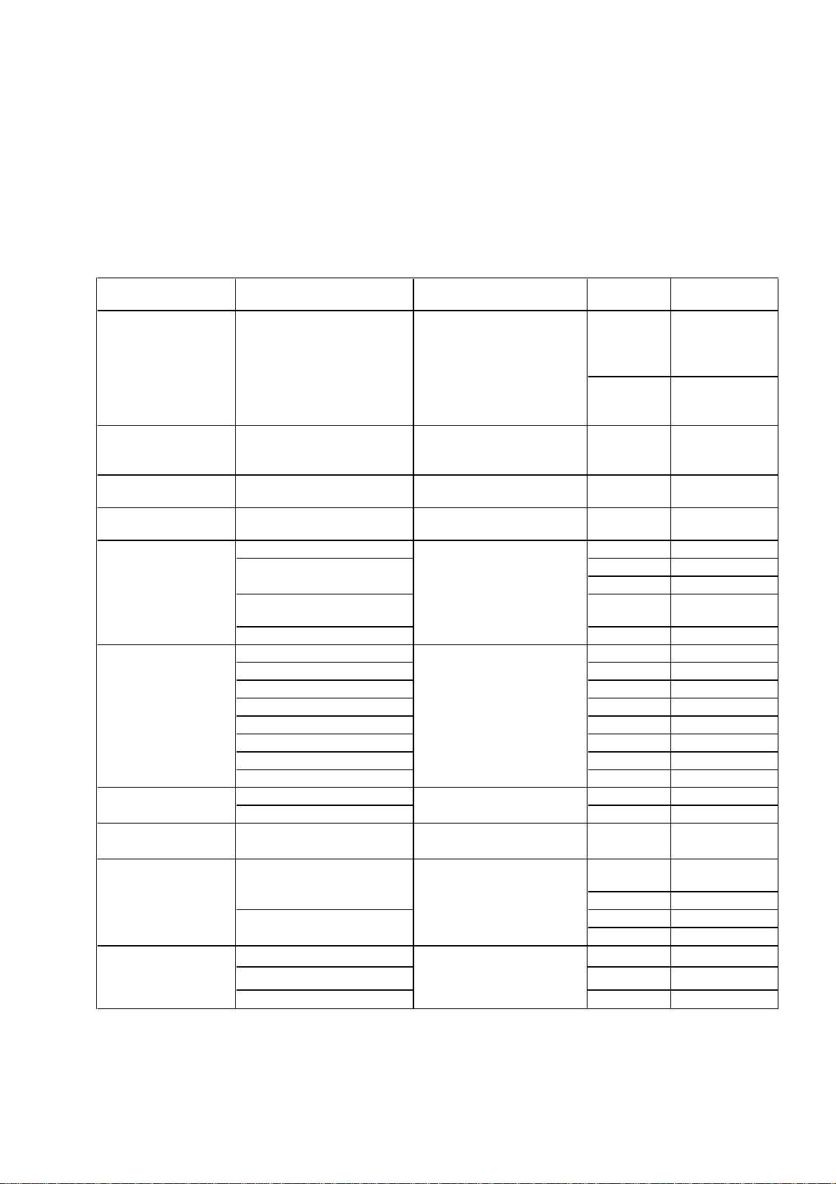
Replaced parts
Block Mounted parts Board
replacement replacement replacement
Adjusting item Adjustment
VIDEO adjustment Video output level adj.
CAMERA adjustment 1 Flange back adj.
CAMERA adjustment 2 Flange back check
CAMERA adjustment 3 Differencal gain adj.
(Note 2) Color shading adj. & check
F No. compensation
CAMERA adjustment 4
CAMERA adjustment 5
(Note 2)
CAMERA adjustment 6 C MOS linearity check
CAMERA adjustment 7
CAMERA adjustment 8
LCD adjustment
EVF adjustment
(Note 1) Initialization of data
Measure gain adj.
Mechanical shutter adj.
Light value adj.
C MOS low temp. dark def.
C MOS low temp. FD def.
C MOS HL def.
C MOS OF def.
Three continuous def. check
AWB adj. & check
Liner matrix adj.
Strobe adj.
Auto focus illumination check
C MOS high temp. dark & FD Def.
Three continuos def. check
C MOS blinking def.
VCO adj.
Contrast adj.
V-COM adj.
White balance adj.
VCO adj.
Contrast adj.
White balance adj.
LCD unit
Back light unit
EVF unit
Back light unit
(AF illumination LED)
(AFE, A/D conv.)
(Camera PreDSP, Timinng generator)
(Camera DSP)
(Video amp.)
(EVF driver)
(LCD driver)
LCD901
D901
LCD902
D902
D001
IC101
IC102
IC301
IC302
IC201
IC201
(COMPLETE)
(COMPLETE)
(COMPLETE) (Note 3)
Lens block
C MOS block assy (Including CD-588 board and C MOS imager)
Flash unit
LCD block
LCD block
EVF block
EVF block
AF-103 flexible
SY-132 board
SY-132 board
SY-132 board
SY-132 board
SY-132 board
PD-259 board
AF-103 flexible
PD-259 board
SY-132 board
zzz z
zz z
zz z
zz z z
zz z z
zz
z
z
z
z
z
zz z z
zz z z
zz
zzz
z
zz
zz
z
zzz
zz
z
z
z
zzz
zzz
DSC-R1_ADJ
Table 6-1-1
6-3
Page 6
1-2. List of service tools
• Oscilloscope • Color monitor • Thermometer
J-1
J-4
J-7
J-10
Personal computer
(Note 1)
Pattern box PTB-450
J-6082-200-A
or
Small pattern box
PTB-1450
J-6082-557-A
Minipattern box
J-6082-353-B
J-2
HASP key and application
for adjustment (SEUS)
Contact our service headquater of each area
how to get the application for adjustment
(SEUS) and HASP key.
J-5
9 colors chart (Note 2)
For PTB-1450:
J-6082-562-A
J-8
Flange back
adjustment jig
J-6082-563-A
J-11
J-3
USB cable
1-827-038-11
J-6
Clear chart
For PTB-450:
J-6080-621-A
For PTB-1450:
J-6082-560-A
J-9
Siemens star chart
J-6080-875-A
Back ground paper
J-2501-130-A
AC-L15A
1-479-283-33
Fig. 6-1-1
Note1: Personal computer
OS: Windows98/98SE/Me/2000/XP Home/XP Pro
RAM: 256MB or more recommended
USB: 2.0 recommended (also compatible with 1.1)
Two connectors are required.
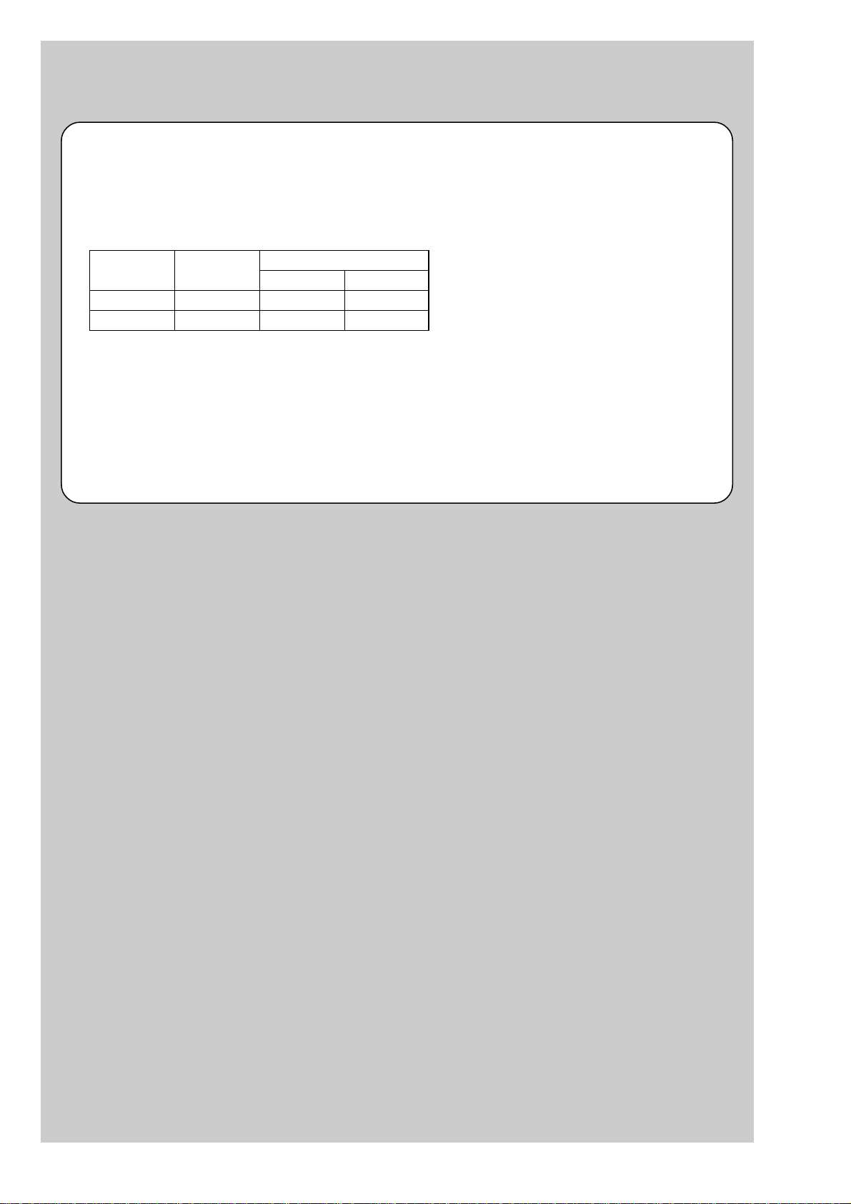
Note2: In using the 9 colors chart on the pattern box PTB-450, adjust the chart size through the procedure shown below so that it
matches to the pattern box PTB-450.
1) Prepare a woody board A of the thickness 5 mm, and paint it mat-black.
2) Fit the 9 colors chart in the woody board A, and secure the chart with a black tape, etc. to shield the light.
AC power adaptor
woody boad A
360 mm
155 mm
135 mm
280 mm
woody boad A
DSC-R1_ADJ
9 colors chart
Fig. 6-1-2
6-4
Page 7

6-1. CAMERA SECTION ADJUSTMENTS
Pattern box
Front of the lens
L = About 5 cm (Zoom at WIDE end)
L = About 30 cm (Zoom at TELE end)
L
Camera
1-1. PREPARATIONS BEFORE ADJUSTMENTS
1-1-1. Preparations
1) Connect the equipment for adjustments according to Fig. 6-1-4.
2) Start up the application for adjustment (SEUS).
Note 1: Before perform the adjustment, set the following data.
1) Select page: 40, address: 38 and set data: 00.
Note 2: After completing all adjustments, reset the camera.
Insert the Memory Stick.
To USB connector
Fig. 6-1-3
PC
OS: Windows 98/98SE/Me/2000/XP
RAM: 256MB or more recommended
USB: 2.0 recommended
(also compatible with 1.1)
Two connectors are required.
AC IN
To DC IN jack
AC power adaptor
To VIDEO OUT jack
HASP Key
USB cable
(1-827-038-11)
Video (yellow)
Fig. 6-1-4
Color monitor
To USB
connector
Video system Adjustment
Osilloscope
Terminated
75 Ω
DSC-R1_ADJ
6-5
Page 8

1-1-2. Precautions
1. Setting the Switch
Unless otherwise specified, set the switches as follows and perform adjustments.
1. Mode dial ........................................... P (Program Auto)
2. FOCUS switch ................................... MANUAL
3. MS/CF switch ................................... MS (Memory Stick)
4. MONITOR switch.............................. PREVIEW
5. USB connect (Menu setting) ........... Mass Storage
6. Video Out (Menu setting) ................. NTSC
9 colors chart (Standard picture frame)
A
Green
Cyan
C14
Effective picture frame
LCD screen or under scan
Fig. a
monitor TV picture
B
Yellow W14
Red
White
Blue
Magenta
A
2. Subjects
1) 9 colors chart (Standard picture frame).
When performing adjustments using the 9 colors chart, adjust
the picture frame as shown in Fig. 6-1-5. (Standard picture
frame)
2) Clear chart (Standard picture frame (WIDE end))
Set the zoom to the WIDE end, and ensure the distance of
about 5 cm from the lens front surface to the clear chart.
Shoot the clear chart, and adjust the camera position so that
a black part of the chart does not fall in all directions of the
screen.
3) Clear chart (Standard picture frame (TELE end))
Set the zoom to the TELE end, and ensure the distance of
about 30 cm from the lens front surface to the clear chart.
Shoot the clear chart, and adjust the camera position so that
a black part of the chart does not fall in all directions of the
screen.
4) Clear chart (For low temp. def.)
Set the zoom to the TELE end, and ensure the distance of below 1 cm from the lens front surface to the clear chart.
Shoot the center of the chart.
C
C
A = B +
B
C =
3
B
C14 : Filter for AWB 5800K adjustment
Transparent window
Fig. 6-1-5
B
3
Adjust the camera position and direction
to obtain the LCD screen or the monitor
TV display shown in Fig. a.
DSC-R1_ADJ
6-6
Page 9

3. Preparing the Flash Adjustment Box
A dark room is required to provide an accurate flash adjustment.
If it is not available, prepare the flash adjustment box as given
below;
1) Provide woody board A, B and C of 15 mm thickness.
woody board A (2)
400 mm
513 mm 513 mm 700 mm
woody board B (2)
Fig. 6-1-6
2) Apply black mat paint to one side of woody board A and B.
3) Attach background paper (J-2501-130-A) to woody board C.
4) Assemble so that the black sides and the background paper
side of woody board A, B and C are internal. (Fig. 6-1-7)
370 mm
700 mm730 mm
woody board A
woody board C (1)
700 mm
woody board B
woody board A
DSC-R1_ADJ
woody board B
woody board C
Fig. 6-1-7
6-7
Page 10
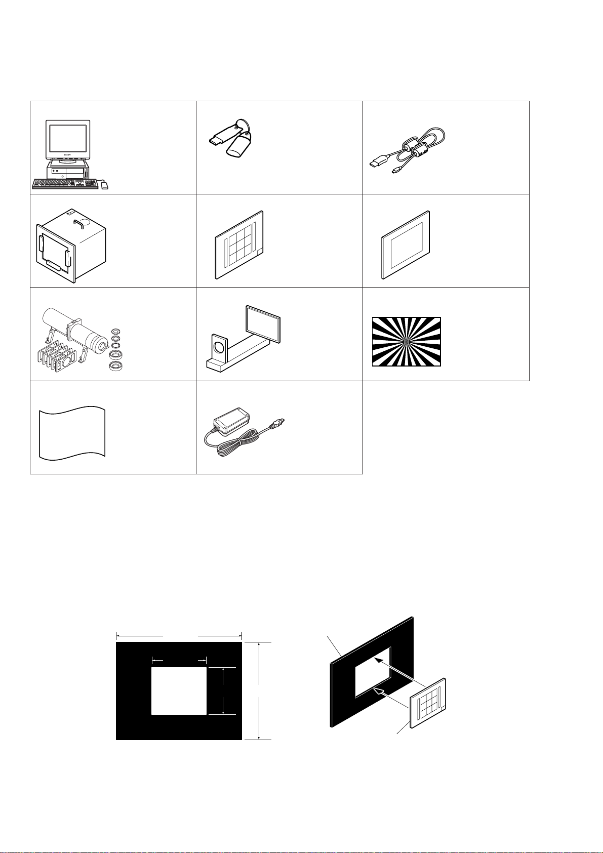
4. Preparation of Aging Environment
To detect a high temperature defect exactly, the aging environment in which the temperature is kept to 40°C - 45°C is required. If there is
not the environment of temperature 40°C to 45°C, prepare the aging environment by the method given below.
Aging environment preparing example
350 mm
400 mm
400 mm
300 mm
40 mm
Thermometer
Small pattern box (PTB-1450)
Cardboard box, etc.
Make a transparent window with film, etc.
Camera to be aged
(Connect the USB cable and
the AC adaptor to the camera)
Place cassette cases under the camera
Attach the height 40mm foot to the four corners
Fig. 6-1-8
1) Prepare a box (such as cardboard box) of 400 mm width × 300 mm depth × 350 mm height. And attach the height 40 mm foot to the
four corners of box.
2) Make a transparent window with film, etc. to check the camera status during the aging.
3) Make a small hole in the box and insert a thermometer to measure the inside temperature.
Note 1: Fix the thermometer at the position free from inter ference with the camera.
4) Cover the small pattern box (PTB-1450), which was turned on, with the prepared box, and wait until the temperature reaches 40°C to
45°C.
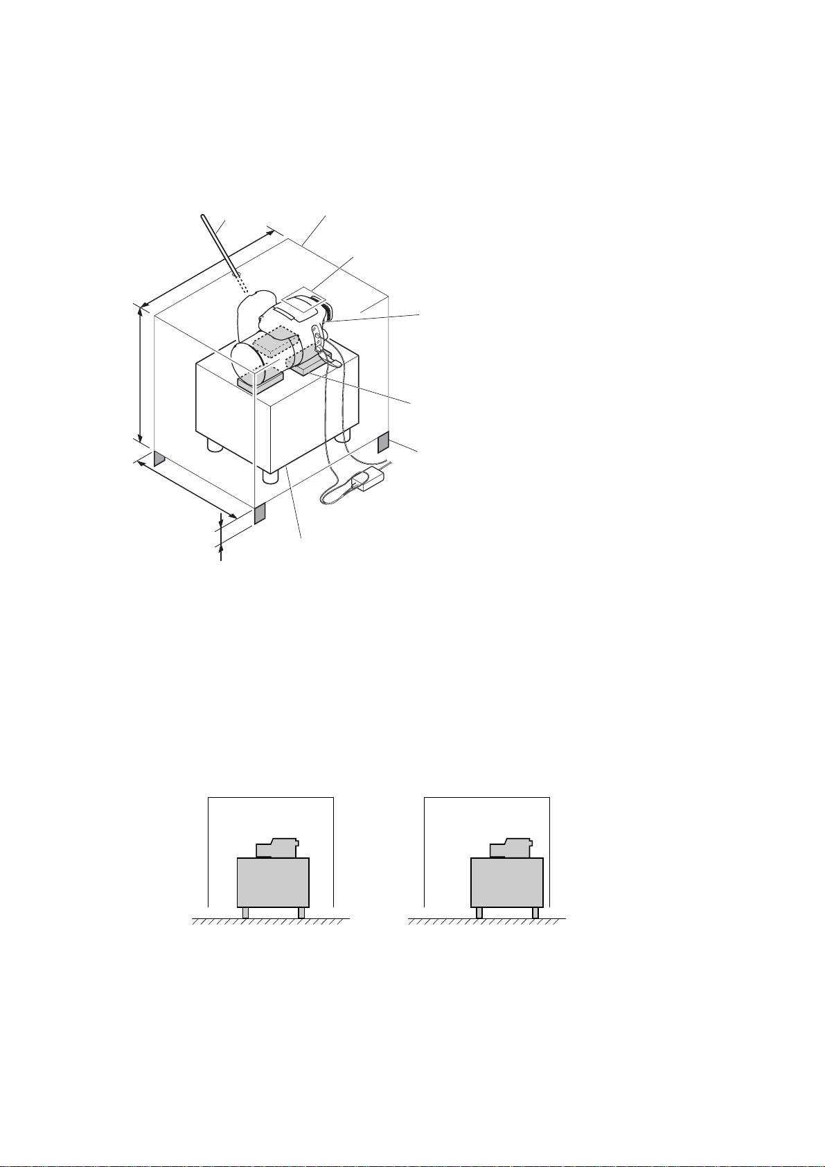
Note 2: To adjust the temperature, move the box. Locating the box in the center of the small pattern box (PTB-
1450) allows the temperature to rise, or shifting it to either side allows the temperature to drop.
Temperature rises when the
box is located in the center
Temperature drops when the
box is shifted to either side
Fig. 6-1-9
5) When the temperature reached 40°C to 45°C, raise the box and place the camera which connects the USB cable and the A C adapter on
the top surface of the small pattern box (PTB-1450), and after turning on the camera, cover with the box again.
Note 3: As the top surface of the small pattern box (PTB-1450) is hot, place cassette cases under the camera,
avoiding a direct touch of camera to the top surface.
6) Adjusting the temperature to keep it to 40°C - 45°C, perform the aging for more than 30 minutes.
DSC-R1_ADJ
6-8
Page 11

1-1-3. Using Method of SEUS
The application for adjustment (SEUS) is used to change the coefficient for calculating the signal processing or EVR data. The SEUS
performs two-way communication between PC and set through
the USB terminal. The two-way communication result data can be
written to the nonvolatile memory.
1. Connection
1) Connect the HASP key to the USB terminal of the PC.
2) Connect the PC and set with the USB cable.
3) Confirm that the set starts in the USB mode.
4) Start the SEUS on the PC.
5) Click [Connect] on the SEUS screen. If the connection is normal, the SEUS screen will be as shown in Fig. 6-1-10, indicating the “connected” state.
Note: The SEUS will go in
turned off (for instance, by resetting the set). In such a
case, click
the “connected” state.
[Connect] on the SEUS screen to restore
“disconnect” state, if the set is
2. Operation
• Page change
To change the page, click
the page to be changed. The page is displayed in hexadecimal
notation.
• Address change
To change the address, click [Address] on the SEUS screen and
enter the address to be changed. The address is displayed in
hexadecimal notation.
• Data change
To change the data, click [Set] on the SEUS screen and enter
the data. The data is displayed in hexadecimal notation.
This operation does not write the data to the nonvolatile memory .
• Data saving
To write the all changed data to the nonvolatile memory, click
[Page] on the SEUS screen and enter
[Save] on the SEUS screen and wait for more than 3 sec.
• Data reading
The data displayed on the SEUS screen are the data values at
the time when the pages and addresses were set, and they are
not updated automatically. To check the data change, click
[Read] on the SEUS screen and update the displayed data.
1-1-4. Precaution on Use of SEUS
Wrong SEUS operation could clear correct adjustment data. To
prevent the data clear by mistake, it is recommended to save all
adjustment data by clicking [Page Edit] on the SEUS screen before starting the adjustment.
Fig. 6-1-10
Saving Method:
1) Click
2) Click [Page], and enter the page number to be saved.
3) Click [Read] to read the data to be saved from the camera.
4) Click [File] and save the data to PC.
Loading Method:
1) Select page: 00, address: 01 and set data: 01.
2) Click [Page Edit] on the SEUS screen to display the SEUS
3) Click [File] and load the data from PC.
4) Click [Write] on the SEUS PAGE EDIT screen.
5) Click [Close] to close the SEUS PAGE EDIT screen.
6) Select page: 40, address: 38 and set data: 00.
7) Click [Save] on the SEUS screen.
8) Select page: 80, address: 34, and check that the data is “00”.
9) Select page: 80, address: 30, and check that the data is “00”.
10) Select page: 00, address: 01 and set data: 00.
[Page Edit] on the SEUS screen to display the SEUS
PAGE EDIT screen.
PAGE EDIT screen.
DSC-R1_ADJ
6-9
Page 12
1-2. ADJUSTMENT PROGRAMS
The DSC-R1 is adjusted with the Automatic Adjustment Program
and the Color Adjustment Program.
The Automatic Adjustment Program automatically controls the
adjustment operations that were formerly entered manually on the
operation screen of the SEUS (some adjustments may be manually operated on the SEUS operation screen).
The Color Adjustment Program automatically performs “Color
Shading Adj. & Check” “AWB Adj. & Check” and “Liner Matrix
Adj.” of Camera System Adjustment.
1-2-1. Automatic Adjustment Program
1. Precautions When Using Automatic Adjustment
Program
1) The Automatic Adjustment Program writes the adjustment re-
sults such as EVR data to the set through two-way communication with the camera via the SEUS. Accordingly, the Automatic Adjustment Program must be used in the environment
where the SEUS operates.
2) The program run time may vary depending on the environ-
ment of the personal computer used.
3) The SEUS must be already started on the PC when using the
Automatic Adjustment Program. With the SEUS not started,
some adjustment items will take time in adjustment.
2. Start of Automatic Adjustment Program
Double-click the application file (DSC-R1 Auto-Adj Ver_1.[]r
and the Automatic Adjustment Program will start.
[][]
.exe),
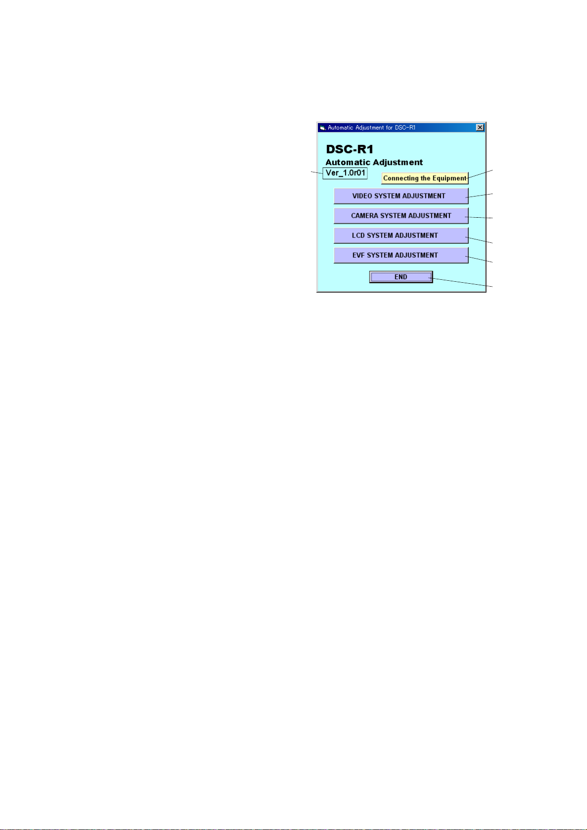
3. Function of Each Button on Main Menu Screen
When the Automatic Adjustment Program started, the Main Menu
screen in Fig. 6-1-11 will appear. On this screen, select each adjustment section.
7
1
2
3
4
5
6
Fig. 6-1-11
1 [Connecting the Equipment] button
A connection diagram of the equipment is displayed.
2 [VIDEO SYSTEM ADJUSTMENT] button
The “VIDEO SYSTEM ADJUSTMENT” screen appears.
Note:[] (numeric value) of the file name v ar ies depending on the
version of Automatic Adjustment Program.
3 [CAMERA SYSTEM ADJUSTMENT] button
The “CAMERA SYSTEM ADJUSTMENT” screen appears.
[LCD SYSTEM ADJUSTMENT] button
4
The “LCD SYSTEM ADJUSTMENT” screen appears.
5 [EVF SYSTEM ADJUSTMENT] button
The “EVF SYSTEM ADJUSTMENT” screen appears.
6 [END] button
The Automatic Adjustment Program finishes.
7 This part indicates the version of Automatic Adjustment Pro-
gram.
DSC-R1_ADJ
6-10
Page 13

1-2-2. Color Adjustment Program
4
3
2
1
A
1. Application Environment
OS: Windows 98/98SE/Me/2000/XP
RAM: 256MB or more recommended
USB: 2.0 recommended (also compatible with 1.1)
Two connectors are required.
2. Installation Method
Extract the file compressed in the ZIP format (R1 Color Adjustment.zip).
Execute the extracted file (R1_setup.exe), and the installer will
start. Install the program following the instructions given on the
installer screen.
3. Notes When Using the Color Adjustment Program
1) The SEUS must be installed in the PC.
2) The HASP Key for SEUS must be connected to the USB connector. The program will not start unless the HASP Key is
connected.
4. Starting Method of AWB Adjustment Program
Click the [Start] button on the task bar, and click the [DSC-R1
Color Adjustment] from the [Programs], and the program will
start.
5. Screen and Function of Each Button of Color
Adjustment Program
Fig. 6-1-12
1 [Connect] button
Makes connection to the camera and switches the camera to
the adjustment mode. In the case of successful connection to
the camera, the indication at the part A changes to “Connected”
and the following buttons become active.
• [Color Shading Adjustment] button
• [AWB Adjustment and Check] button
• [Liner Matrix Adjustment] button
• [Disconnect] button
2 Adjustment start buttons
Start the adjustment or checking of respective button names.
[Disconnect] button
3
Cancels the connection to the camera.
4 Captured picture display screen
Displays a picture captured by the camera when the adjustment or checking was performed.
DSC-R1_ADJ
6-11
Page 14
1-3. VIDEO SYSTEM ADJUSTMENTS
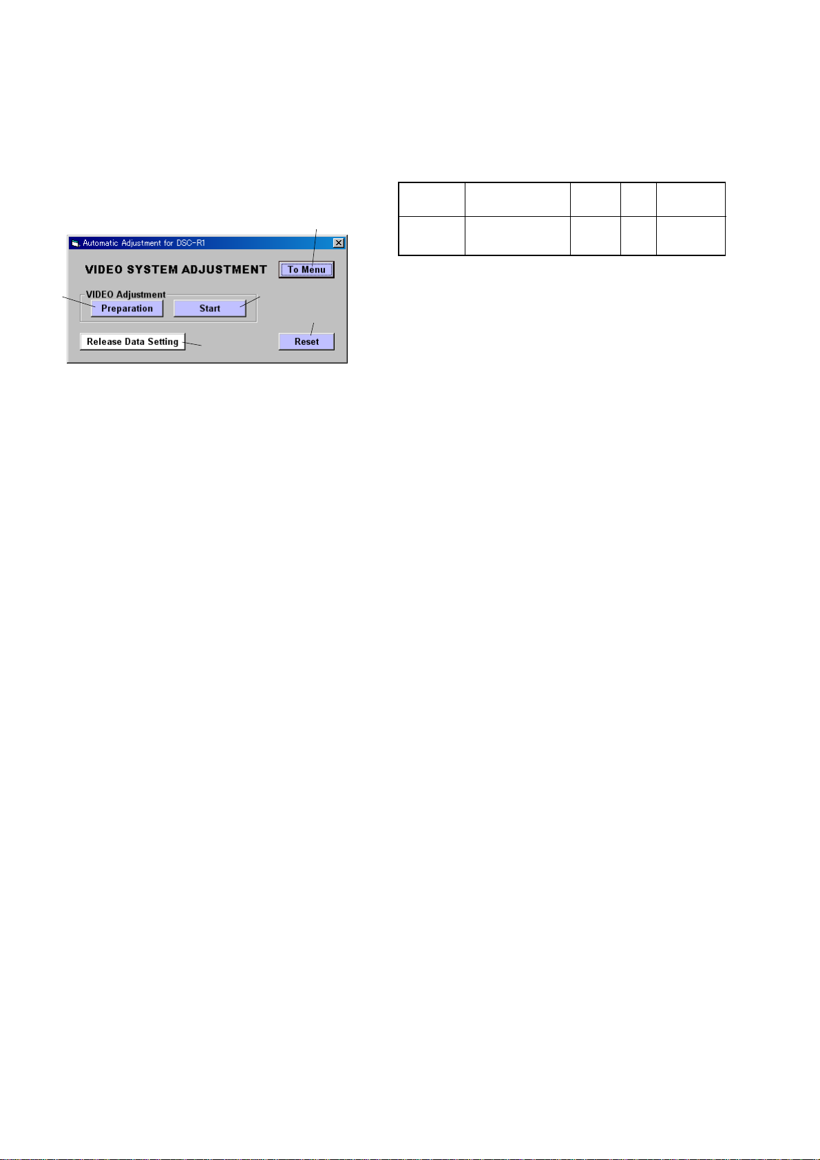
1-3-1. Function of Each Button on Video System
Adjustment Screen
Click the [VIDEO SYSTEM ADJUSTMENT] button on the Main
Menu screen, and the “VIDEO SYSTEM ADJUSTMENT” screen
in Fig. 6-1-13 will appear.
1
2
5
Fig. 6-1-13
1 [To Menu] button
The Main Menu screen comes back.
2 [Preparation] button
Notes for adjustment or jigs usd are displayed.
3
4
1-3-2. Adjustment Items of VIDEO System
Adjustment
The adjustment items of video system adjustment are as listed in
Table 6-1-2. The Automatic Adjustment Program ex ecutes the adjustment items if the VIDEO Adjustment Start button is clicked.
Button
Name
VIDEO VIDEO Output
Adjustment Level Adj.
Adjustment Signal Page Address
Arbitrary 8F D0
Table 6-1-2
3 [Start] button
“Video Adjustment” starts.
4 [Reset] button
This button functions same as the Reset button of the camera.
[Release Data Setting] button
5
The data setting at the adjustment is cancelled.
During the data setting, the button color changes from “white”
to “red”. When the data setting is cancelled, the button color
returns to “white”.
(Use this button when an error occurred in the video adjustment. If the adjustment completed successfully, the data setting is automatically cancelled and the button color returns to
“white”.)
DSC-R1_ADJ
6-12
Page 15

1-3-3. Adjusting Method
[Automatic Adjustment Program execution items and
sequence]
1. Data Setting during Video Adj.
2. Video Output Level Adj.
3. Release of Data Setting during Video Adj.
[Specified value of video output level adj.]
Measurement Point VIDEO OUT jack
(75 Ω terminated)
Measuring Instrument Oscilloscope
Specified V alue Sync level:
A = 286 ± 5 mV (NTSC mode)
A = 300 ± 5 mV (PAL mode)
Burst level:
B = 286 ± 30 mV (NTSC mode)
B = 300 ± 30 mV (PAL mode)
[Adjusting method]
1) Click the [Start] button of the VIDEO Adjustment.
2) The Automatic Adjustment Program executes the “1. Data Setting during Video Adj.”.
3) If “1. Data Setting during V ideo Adj.” completed successfully ,
the next message is displayed during the execution of “2. V ideo
Output Level Adj.”. Using the UP/DOWN key on the SEUS
Operation screen, adjust so that the sync level of the video
signals satisfies the specified value. After the adjustment, check
that the burst level of the video signals satisfies the specified
value, and click the [OK] button in the message.
SEUS operation screen
UP/DOWN key
Fig. 6-1-16
Check on the oscilloscope
B
A
Fig. 6-1-14
4) If the [OK] button button is clicked, “3. Release of Data Setting during Video Adj.” will be executed.
5) Upon successful completion of all items of the VIDEO Adjustment, the following message is displayed. Click the [OK]
button.
Fig. 6-1-15
H
Fig. 6-1-17
DSC-R1_ADJ
6-13
Page 16

1-4. CAMERA SYSTEM ADJUSTMENTS
1-4-1. Function of Each Button on Camera System
Adjustment Screen
Click the [CAMERA SYSTEM ADJUSTMENT] button on the Main
Menu screen, and the “CAMERA SYSTEM ADJUSTMENT”
screen in Fig. 6-1-18 will appear.
1
2
3
2
6
3
3
4
Fig. 6-1-18
1 [To Menu] button
The Main Menu screen comes back.
2 [Preparation] button
Notes for adjustment or jigs used are displayed.
3 [Start] button
Each adjustment from “Camera Adjustment 1” to “Camera
Adjustment 6” starts.
4
[Before Aging] button
Set the timer to 30 minutes in the camera. After setting, turn
off and on the camera, and after 3 seconds, the LCD screen
color will become red, and after 30 minutes, the LCD screen
color will change from red to black. (This is used for the aging
in CAMERA Adjustment 8.)
5
5 [Reset] button
This button functions same as the Reset button of the camera.
6 [Release Data Setting] button
The data setting at the adjustment is cancelled.
During the data setting, the button color changes from “white”
to “red”. When the data setting is cancelled, the button color
returns to “white”.
(Use this button when an error occurred in the camera adjustment 1-8. If the adjustment completed successfully, the data
setting is automatically cancelled and the button color returns
to “white”.)
DSC-R1_ADJ
6-14
Page 17
1-4-2. Adjustment Items of Camera System Adjust-
Button Name Adjustment Subject
Adjustment
Page
Adjustment
Address
6D
1C, 1D, 20, 24,
26 to 39, 3E,
40 to 53, 56, 57
6F
1C, 1D, 20, 24,
26 to 39, 3E,
40 to 67, 6C to 6F,
71 to 79
CAMERA Adjustment 2 Flange Back Check
Siemens star
(1.0m from front the lens)
(Luminance: 200 to 400 lux)
-
-
CAMERA Adjustment 3 Differencial Gain Adj.
Clear chart
(Zoom lens at Wide end)
6B
00 to 45, F0
(Note 1) Color Shading Adj. & Check
Clear chart
(Zoom lens at Wide end)
6F
06, 07
F No. Compensation 6B 5A to 5E, F0 to F2
6B 64, F0
78 0C to 0F, C0 to CA
Mechanical Shutter Adj. 6B
80 to 8B, 98 to 9D,
F0 to F2
Light Value Adj. 6B 61, 62
C MOS Low Temp. Dark Def. - C MOS Low Temp. FD Def. - C MOS HL (Green) Def. - C MOS HL (Red) Def. - C MOS HL (Blue) Def. - C MOS HL (Dark) Def. - C MOS OF Def. - Three Continuos Def. Check - AWB Adj. & Check 6E 00 to 21, 24 to 49
Liner Matrix Adj. 6E 80 to 9F
CAMERA Adjustment 6 C MOS Linearity Check
Clear chart
(Zoom lens at Tele end)
--
6B
C0, C2 to DD,
F3 to F5
6E 72 to 75
6D B8 to BF
6F 10 to 15
CAMERA Adjustment 1 Flange Back Adj.
Siemens star chart with ND filter
for minipattern box (Note 2) or
Flange back adjustment jig
Measure Gain Adj.
CAMERA Adjustment 4
Clear chart
(Zoom lens at Wide end)
CAMERA Adjustment 5
Clear chart
C MOS High Temp. Dark & FD Def.
--
Three Continuos Def. Check
--
C MOS Blinking Def.
--
CAMERA Adjustment 8 Arbitrary
(Zoom lens at Tele end)
(Below 1cm from front the lens)
Strobe Adj.
9 color chart
(Standard picture frame)
(Note 1)
CAMERA Adjustment 7
Auto Focus Illumination Check
Flash adjustment box (50 cm)
ment
The adjustment items of camera system adjustment are as listed in
Table 6-1-3. The Automatic Adjustment Program divides the adjustment items into eight, camera adjustment 1-8. Clicking either
CAMERA Adjustment Start button allows the adjustment item
which corresponds to that button to be executed.
The adjustment conditions of the subject and filter vary depending on which item is adjusted. The Adjustment Program displays
an instruction for the subject and filter as a message during the
adjustment.
Note 1: Use the Color Adjustment Program (R1ColorAdjustment.exe).
DSC-R1_ADJ
Note 2: Dark Siemens star chart.
Table 6-1-3
6-15
Page 18

1-4-3. Adjusting Method
1. CAMERA Adjustment 1
[Automatic Adjustment Program execution items and
sequence]
1. Data Setting during Camera Adj.
2. Flange Back Adj.
3. Release of Data Setting during Camera Adj.
Preparation of Flange Back Adj.
(Using the minipattern box)
1) The minipattern box is installed as shown in the following figure.
Note: The attachment lenses are not used.
2) Set the zoom to the TELE end, and install the minipattern box
so that the distance between it and the front of lens of camera
is less than 1 cm.
3) Make the height of minipattern box and the camera equal.
4) Check the output voltage of the regulated power supply is the
specified voltage ± 0.01 Vdc.
5) Check that the center of Siemens star chart meets the center of
shot image screen with the zoom lens at TELE end and WIDE
end respectively.
Specified voltage:The specified voltage varies according to the
minipattern box, so adjustment the power supply output voltage to the specified voltage written on the sheet which is supplied with the minipattern box.
Below 1 cm
Preparation of Flange Back Adj.
(Using the flange back adjustment jig)
(Luminance: about 300 lux)
1) Set the zoom to the TELE end, install the flange back adjustment jig so that the distance between it and the front of lens of
camera is less than 1 cm.
2) Make the height of flange back adjustment jig and the camera
equal.
3) Check that the center of chart meets the center of shot image
screen with the zoom lens at TELE end and WIDE end respectively.
Flange back adjustment jig
Below 1 cm
Camera
Fig. 6-1-20
Minipattern box
Output voltage : Specified voltage ± 0.01 Vdc
Red (+)
Black (–)
Yellow (SENS +)
White (SENS –)
Black (GND)
Camera
Regulated power supply
Output current : more than 3.5 A
Need not connected
Fig. 6-1-19
DSC-R1_ADJ
6-16
Page 19
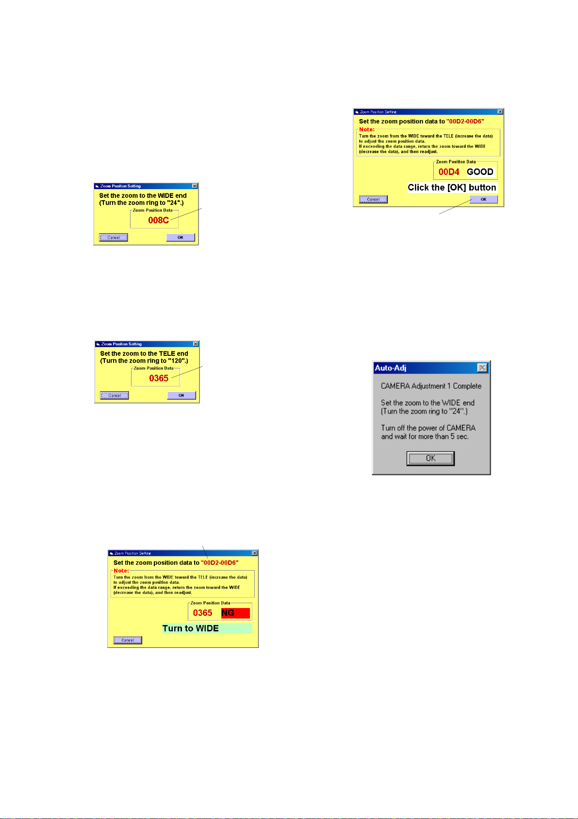
[Adjusting method]
1) Click the [Start] button of Camera Adjustment 1.
2) The automatic adjustment program executes “1. Data Setting
during Camera Adj.”.
3) When “1. Data Setting during Camera Adj.” completed successfully, the following screen will appear during execution
of “2. Flange Back Adjustment”. Set the zoom to the WIDE
end, and check the setting of the subject.
(For the subject setting, see “Preparation for Flange Back Adjustment”.)
With the zoom at the WIDE end,
the data becomes minimum value.
6) When the zoom position data becomes the specified value, the
screen will change as shown below. Check the setting of the
subject, and then click the [OK] button on the screen.
If the data fulfills the specified value,
the [OK] button is displayed.
Fig. 6-1-24
Fig. 6-1-21
4) Click the [OK] button to execute the adjustment. Upon suc-
cessful completion of adjustment, the following screen will
appear.
Set the zoom to the TELE end, and check the setting of the
subject.
With the zoom at the TELE end,
the data becomes maximum value.
Fig. 6-1-22
5) Click the [OK] button to execute the adjustment. Upon suc-
cessful completion of adjustment, the following screen will
appear. Following the instruction on the screen, operate the
camera zoom to adjust the zoom position data to the specified
value.
Note: Turn the zoom from the WIDE toward the TELE (in
crease the data) to adjust the zoom position data.
If exceeding the data range, return the zoom toward
the WIDE (decrease the data), and then readjust.
Adjust the zoom position data
to the value displayed here.
7) Repeat step 5) and 6) seven times, and “2. Flange Back Adj.”
completes. Then, execute “3. Release of Data Setting during
Camera Adj.”.
8) Upon successful completion of all items in Camera Adjustment 1, the following message will be displayed. Click the
[OK] button, and then return the zoom to the WIDE end and
turn off the power switch of the camera. To perf orm the next
adjustment, wait for more than 5 seconds before turning on
the power switch.
Fig. 6-1-25
DSC-R1_ADJ
Fig. 6-1-23
6-17
Page 20

2. CAMERA Adjustment 2
[Automatic Adjustment Program execution items and
sequence]
1. Data Setting during Camera Adj.
2. Flange Back Check
3. Release of Data Setting during Camera Adj.
[Adjusting method]
1) Click the [Start] button of the CAMERA Adjustment 2.
2) The Automatic Adjustment Program e xecutes “1. Data Setting
during Camera Adj.”.
3) Upon successful completion of the “1. Data Setting during
Camera Adj. ”, the follo wing message is displayed. Set the subject in accordance with the message.
Fig. 6-1-26
4) Click the [OK] button is clicked, “2. Flange Back Check” is
executed. The following messages are displayed, and then operate the camera to make a check in accordance with the messages.
Fig. 6-1-27
5) Upon completion of “2. Flange Back Check”, “3. Release of
Data Setting during Camera Adj.” is executed.
6) Upon successful completion of all items of the CAMERA
Adjustment 2, the following message is displayed. Click the
[OK] button.
Fig. 6-1-28
DSC-R1_ADJ
6-18
Page 21

3. CAMERA Adjustment 3
[Automatic Adjustment Program execution items and
sequence]
1. Data Setting during Camera Adj.
2. Differencial Gain Adj.
3. Release of Data Setting during Camera Adj.
[Adjusting method]
1) Click the [Start] button of the CAMERA Adjustment 3.
2) The Automatic Adjustment Program executes the “1. Data Setting during Camera Adj.”.
3) Upon successful completion of “1. Data Setting during Camera Adj.”, the following screen is displayed. Set the zoom to
the WIDE end.
With the zoom at the WIDE end,
the data becomes minimum value.
Fig. 6-1-29
4) If the [OK] button is clicked, the following message is displayed. Set the subject in accordance with the message.
Fig. 6-1-30
5) Click the [OK] button, and the “2. Dif ferencial Gain Adj.” and
“3. Release of Data Setting during Camera Adj.” will be executed.
6) Upon successful completion of all items of the CAMERA
Adjustment 3, the following message is displayed. Click the
[OK] button.
Fig. 6-1-31
DSC-R1_ADJ
6-19
Page 22
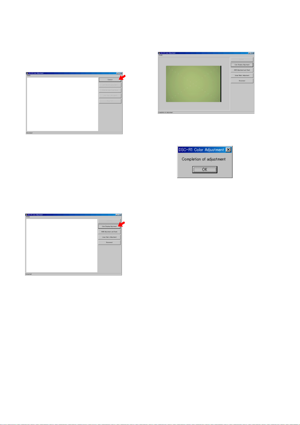
4. Color Shading Adjustment & Check
[Adjustment method]
1) Start the Color Adjustment Program
(R1ColorAdjustment.exe).
2) Click the [Connect] button to set the camera to the adjustment mode.
Fig. 6-1-32
3) Set the mode dial of the camera to “P”, and shoot the clear
chart with the zoom at the WIDE end. (The distance from the
lens front surface to the clear chart is about 5 cm.)
4) Set the FOCUS switch to “MANUAL”, and rotate the focus
ring to set the distance to “0.35 m”.
5) Adjust the camera direction and distance so that a black part
of the chart does not fall in all directions of the screen.
Note 1: At this time, nothing must be reflected in the clear
chart.
7) A picture captured by the camera is displayed on the screen,
and the adjustment and checking are performed.
Fig. 6-1-34
8) Upon successful completion of the adjustment, the following
message is displayed. Click the [OK] button.
Fig. 6-1-35
6) Click the [Color Shading Adjustment] button.
Fig. 6-1-33
DSC-R1_ADJ
6-20
Page 23
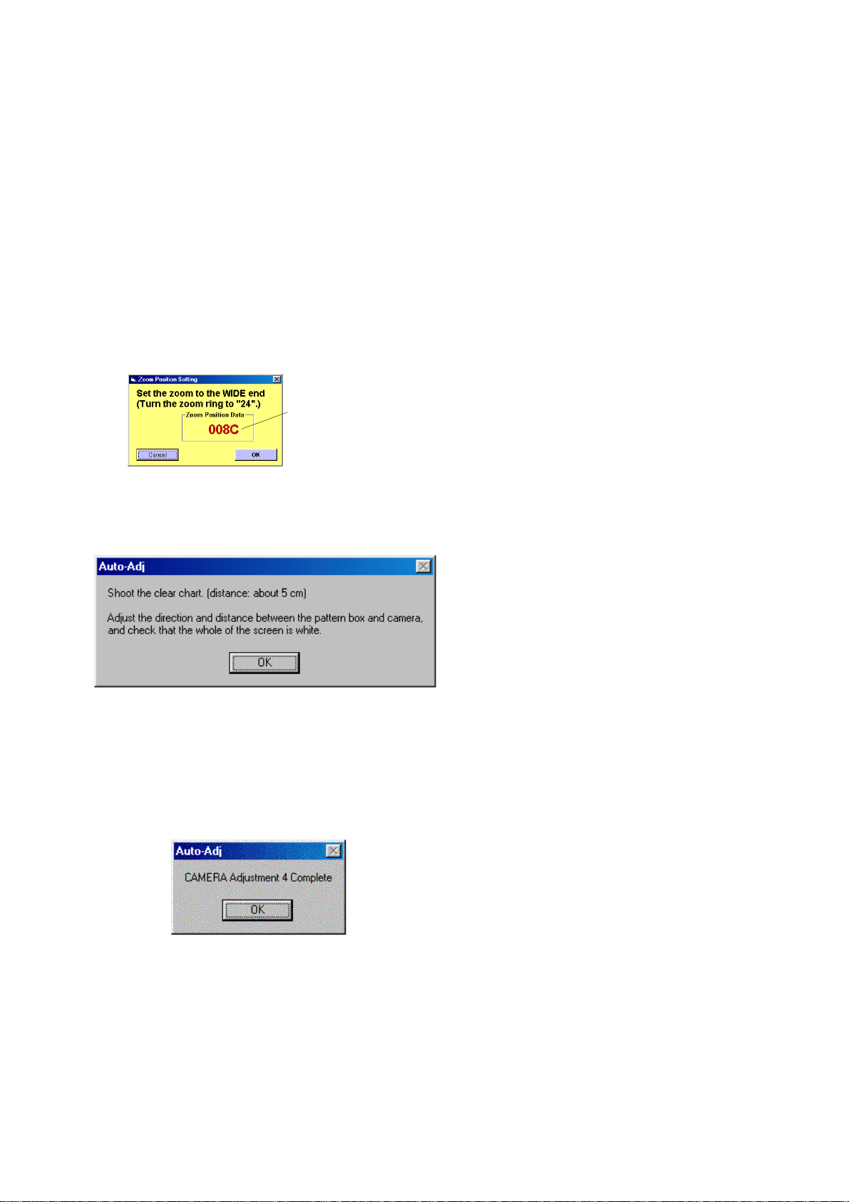
5. CAMERA Adjustment 4
[Automatic Adjustment Program execution items and
sequence]
1. Data Setting during Camera Adj.
2. F No. Compensation
3. Measure Gain Adj.
4. Mechanical Shutter Adj.
5. Light V alue Adj.
6. Release of Data Setting during Camera Adj.
[Adjusting method]
1) Click the [Start] button of the CAMERA Adjustment 4.
2) The Automatic Adjustment Program executes the “1. Data Setting during Camera Adj.”.
3) Upon successful completion of “1. Data Setting during Camera Adj.”, the following screen is displayed. Set the zoom to
the WIDE end.
With the zoom at the WIDE end,
the data becomes minimum value.
Fig. 6-1-36
4) If the [OK] button is clicked, the following message is displayed. Set the subject in accordance with the message.
Fig. 6-1-37
5) Click the [OK] button, and the items from “2. F No. Compensation” to “6. Release of Data Setting during Camera Adj.”
will be executed.
6) Upon successful completion of all items of the CAMERA
Adjustment 4, the following message is displayed. Click the
[OK] button.
DSC-R1_ADJ
Fig. 6-1-38
6-21
Page 24
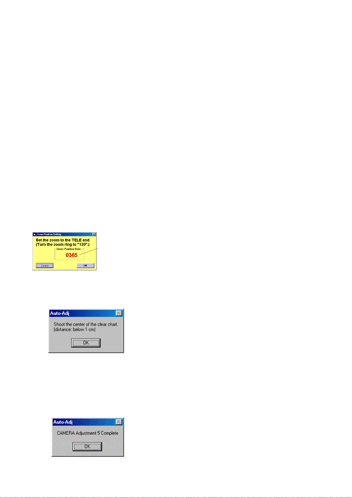
6. CAMERA Adjustment 5
[Automatic Adjustment Program execution items and
sequence]
1. Data Setting during Camera Adj.
2. Preparation before Defect Adj.
3. System Reset
4. Data Setting during Camera Adj.
5. C MOS Low Temp. Dark Def.
6. C MOS Low Temp. FD Def.
7. C MOS HL (Green) Def.
8. C MOS HL (Red) Def.
9. C MOS HL (Blue) Def.
10. C MOS HL (Dark) Def.
11. C MOS OF Def.
12. Three Continuos Def. Check
13. Release of Data Setting during Camera Adj.
[Adjusting method]
1) Click the [Start] button of CAMERA Adjustment 5.
2) The Automatic Adjustment Program executes the “1. Data Set
ting during Camera Adj.” and “2. Preparation before Defect
Adj.”.
3) Upon successful completion of “2. Preparation before Defect
Adj.”, “3. System Reset” is ex ecuted. At this time, the camera
is reset and power is turns off once and then on again. After
that, “4. Data Setting during Camera Adj.” is executed.
4) Upon successful completion of “4. Data Setting during Camera Adj.”, the following screen is displayed. Set the zoom to
the TELE end.
With the zoom at the TELE end,
the data becomes maximum value.
Fig. 6-1-39
5) If the [OK] button is clicked, the following message is dis-
played. Set the subject in accordance with the message.
Fig. 6-1-40
6) Click the [OK] button, and the items from “5. C MOS Low
Temp. Dark Def.” to “13. Release of Data Setting during Camera Adj.” will be executed.
7) Upon successful completion of all items of the CAMERA Adjustment 5, the following message is displayed. Click the [OK]
button.
DSC-R1_ADJ
Fig. 6-1-41
6-22
Page 25

7. Picture Frame Setting (Standard Picture Frame)
In the “AWB Adjustment & Check” and “Liner Matrix Adjustment”, set the picture frame so as to attain the positions shown in
the following figure when shooting the 9 colors chart.
Check on the oscilloscope
Measurement Point:VIDEO OUT jack
(75 Ω terminated)
1. Horizontal period
A = B +
A
B
3
B
A
Fig. 6-1-42
2. Vertical period
B
V
C =
CC
B
3
Fig. 6-1-43
Check on the monitor TV or the LCD screen
A = B +
C14 : Filter for AWB 5800K adjustment
B
3
Cyan
C14
BA
YellowGreen
White
Blue
C =
W14
Red
Magenta
B
3
A
C
B
C
DSC-R1_ADJ
Effective picture frame
Transparent window
Fig. 6-1-44
6-23
Page 26
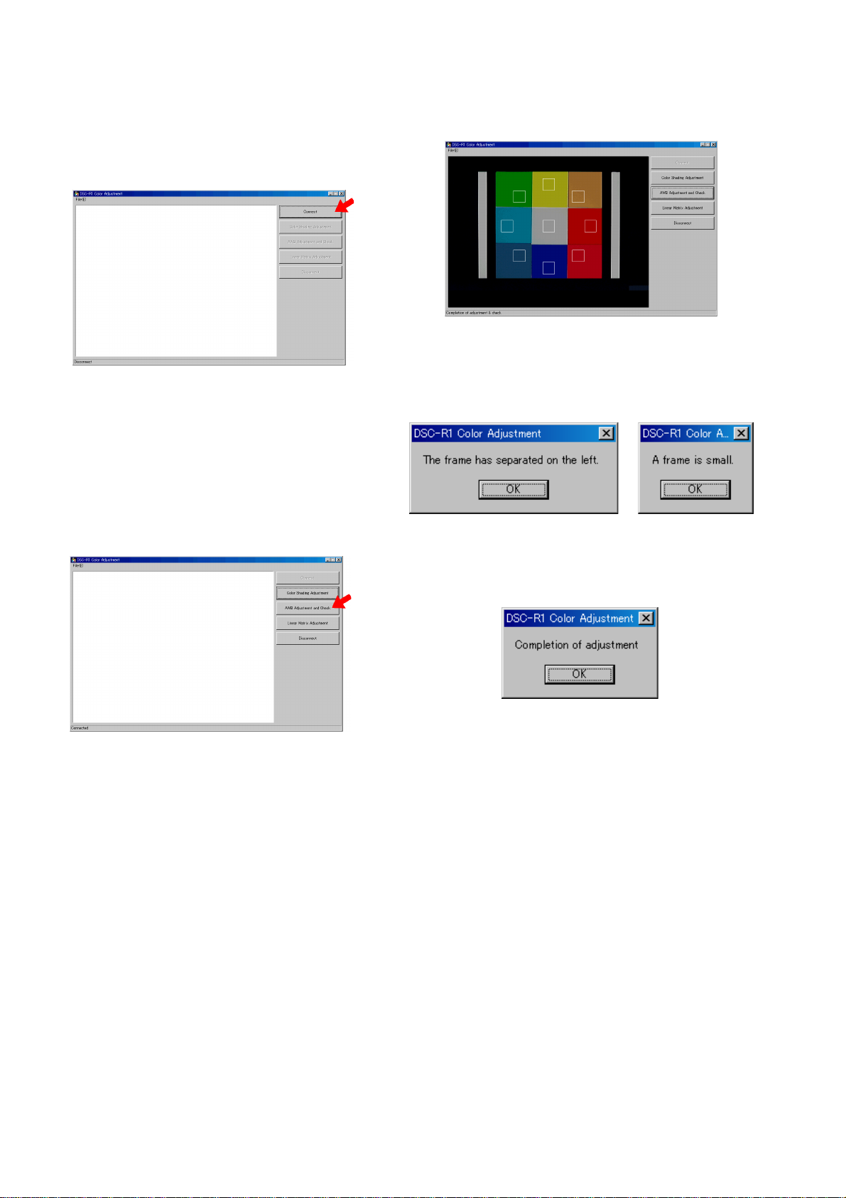
8. AWB Adjustment & Check
[Adjustment method]
1) Start the Color Adjustment Program (R1ColorAdjustment.ex e).
2) Click the [Connect] button to set the camera to the adjustment mode.
Fig. 6-1-45
3) Set the mode dial of the camera to “P”, and shoot the 9 colors
chart with the zoom at the WIDE end. (The distance from the
lens front surface to the 9 colors chart is 35 cm.) And then,
turn the zoom ring to the TELE end.
4) Adjust the camera direction and distance to set the picture
frame. (See 7. Picture Frame Setting)
5) Set the FOCUS switch to “MANUAL” .
Using the focus ring, adjust the focus.
6) Click the [AWB 3200K-5800K Standard Data Input] button.
7) A picture captured by the camera is displayed on the screen,
and the adjustment and checking are performed.
Fig. 6-1-47
Note: If the following message is displayed, the picture frame
setting is faulty . Check the picture frame, and then perform
readjustment.
Fig. 6-1-48
Fig. 6-1-46
8) Upon successful completion of the adjustment, the following
message is displayed. Click the [OK] button.
Fig. 6-1-49
DSC-R1_ADJ
6-24
Page 27

9. Linear Matrix Adjustment
9-1. Preparation for Linear Matrix Adjustment (Getting
Reference Data)
This work gets the reference data used for linear matrix adjustment by using a camera on which the DSC-R1 runs normally. The
gotten reference data is saved in a personal computer. Accordingly, once the reference data is gotten, this work is no longer
needed unless the adjustment conditions (pattern box, 9 colors
chart, etc.) are changed.
The reference data is saved with the file name “GodRa wData.csv”
in the directory where the color adjustment program
(R1ColorAdjustment.exe) file exists.
Note 1: The linear matrix adjustment will fail if an unadjusted
camera is used to get the reference data. The camera that
has already been adjusted must be used.
[Adjusting method]
1) Start the color adjustment program (R1ColorAdjustment.exe).
2) Click the [Connect] button to activate the camera adjustment
mode.
7) The camera capture picture is displayed on the screen to get
and save the reference data.
Fig. 6-1-52
Note 3: If the following message is displayed, the picture frame
setting is faulty. Check the picture frame, and then per
form readjustment.
Fig. 6-1-50
3) Set the mode dial of the camera to “P”, and shoot the 9 colors
chart with the zoom at the WIDE end. (The distance from the
lens front surface to the 9 colors chart is 35 cm.) And then,
turn the zoom ring to the TELE end.
4) Adjust the camera direction and distance to set the picture
frame. (See 7. Picture Frame Setting)
5) Set the FOCUS switch to “MANUAL” .
Using the focus ring, adjust the focus.
6) Click the [Get Reference] of the file menu.
Note 2: When a message “file over write?” is displayed, the ref
erence data file (GodRawData.csv) already exists. If you
click the [OK] button, new ref erence data is written ov er
the existing data.
Fig. 6-1-53
8) Upon successful completion, the following message will be
displayed. Click the [OK] button.
Fig. 6-1-54
DSC-R1_ADJ
Fig. 6-1-51
6-25
Page 28

9-2. Linear Matrix Adjustment
[Adjusting method]
1) Start the color adjustment program (R1ColorAdjustment.exe).
2) Click the [Connect] button to activate the camera adjustment
mode.
Fig. 6-1-55
3) Set the mode dial of the camera to “P”, and shoot the 9 colors
chart with the zoom at the WIDE end. (The distance from the
lens front surface to the 9 colors chart is 35 cm.) And then,
turn the zoom ring to the TELE end.
4) Adjust the camera direction and distance to set the picture
frame. (See 7. Picture Frame Setting)
5) Set the FOCUS switch to “MANUAL” .
Using the focus ring, adjust the focus.
6) Click the [Linear Matrix Adjustment] button.
7) A picture captured by camera is displayed on the screen, and
the adjustment and checking are performed.
Fig. 6-1-57
Note: If the following message is displayed, the picture frame
setting is faulty. Check the picture frame, and then per
form readjustment.
Fig. 6-1-58
Fig. 6-1-56
8) Upon successful completion, the following message will be
displayed. Click the [OK] button.
Fig. 6-1-59
DSC-R1_ADJ
6-26
Page 29

11. CAMERA Adjustment 6
[Automatic Adjustment Program execution items and
sequence]
1. Data Setting during Camera Adj.
2. C MOS Linearity Check
3. Release of Data Setting during Camera Adj.
[Adjusting method]
1) Click the [Start] button of the CAMERA Adjustment 6.
2) The Automatic Adjustment Program executes the “1. Data Setting during Camera Adj.”.
3) Upon successful completion of “1. Data Setting during Camera Adj.”, the following screen is displayed. Set the zoom to
the TELE end.
With the zoom at the TELE end,
the data becomes maximum value.
Fig. 6-1-60
4) If the [OK] button is clicked, the following message is displayed. Set the subject in accordance with the message.
Fig. 6-1-61
5) Click the [OK] button, and the “2. C MOS Linearity Check”
and “3. Release of Data Setting during Camera Adj.” will be
executed.
6) Upon successful completion of all items of the CAMERA
Adjustment 6, the following message is displayed. Click the
[OK] button.
Fig. 6-1-62
DSC-R1_ADJ
6-27
Page 30

11. CAMERA Adjustment 7
Note: “CAMERA Adjustment 7” is available only once after the
power is turned on. If the adjustment is retried, turn off the
power and turn on again.
[Automatic Adjustment Program execution items and
sequence]
1. Data Setting during Camera Adj.
2. Strobe Adj.
3. Auto Focus Illumination Check
4. Release of Data Setting during Camera Adj.
[Adjusting method]
1) Click the [Start] button of the CAMERA Adjustment 7.
2) The Automatic Adjustment Program executes the “1. Data
Setting during Camera Adj.”.
3) Upon successful completion of the “1. Data Setting during
Camera Adj.”, the following screen is displayed. Set the zoom
to the WIDE end.
With the zoom at the WIDE end,
the data becomes minimum value.
Fig. 6-1-63
4) If the [OK] button is clicked, the following message is displayed. Set the subject in accordance with the message.
(For the Flash adjustment box, refer to “3. Preparing the Flash
Adjustment Box” (see page 6-7).)
7) Upon successful completion of “2. Strobe Adj.”, “3. Auto Focus Illumination Check” is executed. The follo wing messages
are displayed, and then attach the AF illumination axis frame
to the monitor TV screen to make a check in accordance with
the messages.
Fig. 6-1-66
8) Upon successful completion of the “3. Auto Focus Illumination Check”, the “4. Release of Data Setting during Camera
Adj.” will be executed successively.
9) Upon successful completion of all items of the CAMERA
Adjustment 7, the following message is displayed. Click the
[OK] button.
Fig. 6-1-64
5) Press the [OK] button, and the “2. Strobe Adj.” will be executed.
6) During execution of “2. Strobe Adj.”, the following message
is displayed. After checking the flashing of strobe light, click
the [OK] button. (This message is displayed 2 times during
execution of adjustment.)
Fig. 6-1-65
Fig. 6-1-67
Check on the monitor TV
Fig. 6-1-68
DSC-R1_ADJ
6-28
Page 31

11. CAMERA Adjustment 8
Note: To detect a high temperature defect in the CAMERA Ad-
justment 8, the camera must be aged for more than 30 minutes at the temperature 40°C to 45°C. The detection of a
defect will fail unless the aging is performed in the environment of exact temperature kept in a range of 40°C to
45°C.
[Automatic Adjustment Program execution items and
sequence]
1. Data Setting during Camera Adj.
2. C MOS High Temp. Dark & FD Def.
3. Three Continuos Def. Check
4. C MOS Blinking Def.
5. Release of Data Setting during Camera Adj.
[Aging method]
1) Click the [Before Aging] button in the CAMERA Adjustment 1.
2) Automatic adjustment program sets the timer to 30 minutes in
the camera.
3) Upon successful completion of setting, the following message
is displayed. Click the [OK] button.
Fig. 6-1-69
4) Disconnect the USB cable from the PC, and then disconnect
the power cord from the AC adaptor. (POWER OFF)
5) Put the camera in the environment of temperature 40°C to 45°C,
and connect the power cord to the AC adaptor. (POWER ON)
(For the aging environment, see “4. Preparation of Aging En-
vironment” (page 6-8).)
6) In about 3 seconds after the power was turned on, the LCD
screen color will become red and the 30-minute timer will start.
7) After 30 minutes elapsed, the LCD screen color will change
from red to black, indicating the completion of aging.
[Adjusting method]
1) Connect the USB cable to the PC.
2) Click the [Start] button in the CAMERA Adjustment 8, and
the following message will be displayed. If the aging has completed, click the [OK] button. Or , if the aging is not performed,
click the [Cancel] button to interrupt the adjustment.
Fig. 6-1-70
3) Click the [OK] button to execute the items from “1. Data Set-
ting during Camera Adj.” to “5. Release of Data Setting during Camera Adj.”.
4) Upon successful completion of all items in the CAMERA Adjustment 8, the following message is displayed. Click the [OK]
button.
Fig. 6-1-71
DSC-R1_ADJ
6-29
Page 32

1-5. LCD SYSTEM ADJUSTMENTS
1-5-1. Function of Each Button on LCD System
Adjustment Screen
Click the [LCD SYSTEM ADJUSTMENT] button on the Main
Menu screen, and the “LCD SYSTEM ADJUSTMENT” screen in
Fig. 6-1-72 will appear.
1
2
1-5-2. Adjustment Items of LCD System Adjustment
The adjustment items of LCD system adjustment are as listed in
Table 6-1-4. The Automatic Adjustment Program ex ecutes the adjustment items if the LCD Adjustment Start button is clicked.
Button
Name
Adjustment Signal Page Address
VCO adj. 8F 23
LCD Contrast adj.
Adjustment V-COM adj. 8F 24
Arbitrary
8F 2C
White Balance adj. 8F 28, 2A
3
4
Fig. 6-1-72
1 [To Menu] button
The Main Menu screen comes back.
2 [Start] button
“LCD Adjustment” starts.
3 [Reset] button
This button functions same as the Reset button of the camera.
4 [Release Data Setting] button
The data setting at the adjustment is cancelled.
During the data setting, the button color changes from “white”
to “red”. When the data setting is cancelled, the button color
returns to “white”.
(Use this button when an error occurred in the LCD adjustment. If the adjustment completed successfully, the data setting is automatically cancelled and the button color returns to
“white”.)
Table 6-1-4
DSC-R1_ADJ
6-30
Page 33

1-5-3. Adjusting Method
[Automatic Adjustment Program execution items and
sequence]
1. Data Setting during LCD Adj.
2. VCO Adj.
3. Contrast Adj.
4. V -COM Adj.
5. White Balance Adj.
6. Release of Data Setting during LCD Adj.
[Adjusting method]
1) Click the [Start] button of the LCD Adjustment.
2) The Automatic Adjustment Program executes the items from
“1. Data Setting during LCD Adj.” to “3. Contrast Adj.”.
3) Upon successful completion of the “3. Contrast Adj.”, the following message is displayed during execution in “4. V-COM
Adj.”. On the SEUS screen, operate the UP/DOWN key so
that the brightness of portions A and B on the LCD panel is
equal. After the adjustment, click the [OK] button.
SEUS operation screen
UP/DOWN key
Fig. 6-1-76
Check on the LCD screen (V-COM Adj.)
A
B
A
B
Fig. 6-1-73
4) Upon completion of “4. V-COM Adj.”, “5. White Balance Adj. ”
is executed. The follo wing message is displayed, and then check
that LCD screen is not colored.
If colored, change the data of page: 8F , address: 28 and 2A on
the SEUS Operation screen to adjust so that the LCD screen is
not colored.
Fig. 6-1-74
5) If the [OK] button is clicked, “6. Release of Data Setting during LCD Adj.” will be executed.
6) Upon successful completion of all item the LCD Adjustment,
the following message is displayed. Click the [OK] button.
B
A
A
B
Fig. 6-1-77
DSC-R1_ADJ
Fig. 6-1-75
6-31
Page 34

1-6. EVF SYSTEM ADJUSTMENTS
1-6-1. Function of Each Button on EVF System
Adjustment Screen
Click the [EVF SYSTEM ADJUSTMENT] button on the Main
Menu screen, and the “EVF SYSTEM ADJUSTMENT” screen in
Fig. 6-1-78 will appear.
1
2
3
4
Fig. 6-1-78
1 [To Menu] button
The Main Menu screen comes back.
2 [Start] button
“EVF Adjustment” starts.
3 [Reset] button
This button functions same as the Reset button of the camera.
4 [Release Data Setting] button
The data setting at the adjustment is cancelled.
During the data setting, the button color changes from “white”
to “red”. When the data setting is cancelled, the button color
returns to “white”.
(Use this button when an error occurred in the EVF adjustment. If the adjustment completed successfully, the data setting is automatically cancelled and the button color returns to
“white”.)
1-6-3. Adjusting Method
[Automatic Adjustment Program execution items and
sequence]
1. Data Setting during EVF Adj.
2. VCO Adj.
3. Contrast Adj.
4. White Balance Adj.
5. Release of Data Setting during EVF Adj.
[Adjusting method]
1) Click the [Start] button of the EVF Adjustment.
2) The Automatic Adjustment Program executes the items from
“1. Data Setting during EVF Adj.” to “3. Contrast Adj.”
3) Upon successful completion of the “3. Contrast Adj.”, “4.
White Balance Adj.” is executed. The following message is
displayed, and then check that EVF screen is not colored.
If colored, change the data of page: 8F, address: 78 and 77 on
the SEUS Operation screen to adjust so that the EVF screen is
not colored.
Fig. 6-1-79
4) If the [OK] button is clicked, “3. Release of Data Setting during EVF Adj.” will be executed.
5) Upon successful completion of all item the EVF Adjustment,
the following message is displayed. Click the
[OK] button.
1-6-2. Adjustment Items of EVF System Adjustment
The adjustment items of EVF system adjustment are as listed in
Table 6-1-5. The Automatic Adjustment Program e xecutes the adjustment items if the EVF Adjustment Start button is clicked.
Button
Name
EVF
Adjustment
Adjustment Signal Page Address
VCO adj. 8F 73
Contrast adj. Arbitrary 8F 7C
White Balance adj. 8F 78, 7A
Table 6-1-5
Fig. 6-1-80
DSC-R1_ADJ
6-32
Page 35

1-7. ERROR
This part indicates
the adjustment
item in which
an error occurred.
In case of an error during the execution of adjustment, the Automatic Adjustment Program interrupts the processing at that point,
and displays an error message, and then terminates the program
execution there.
1-7-1. Error Message
When an error message is displayed, perform the remedy given
below , and then retry adjustment. If the error message is displayed
though the remedy was performed, the circuits will be faulty.
3. Adjustment Time Out
This part indicates
the adjustment
item in which
an error occurred.
Fig. 6-1-83
1. Connect Error
Fig. 6-1-81
Symptom USB communication with the set is abnormal.
Cause • USB cable is not inserted tightly.
• Power supply is not installed correctly.
• Communication with SEUS is abnormal.
Remedy • Disconnect the USB cable once, and then re-
connect it tightly and check that the set is in
“USB Mode”.
• Install the power supply correctly.
• Start the SEUS and click the [Connect] to
check that the connection state is established.
2. RESET the CAMERA and Try Again
Symptom Adjustment does not finish within the specified
time.
Cause • Adjustment conditions are wrong.
• Data error exists in the camera.
Remedy • Check that the conditions such as a subject
are correct.
• Reset the camera.
4. Adjustment NG
Fig. 6-1-84
Symptom The adjusted data does not become the speci-
fied value.
Cause • Adjustment conditions are wrong.
• Data error exists in the camera.
Remedy • Check that the conditions such as a subject
are correct.
• Reset the camera.
Symptom The camera is not ready for adjustment.
Cause • Data error exists in the camera.
Remedy • Reset the camera.
DSC-R1_ADJ
Fig. 6-1-82
6-33
Page 36

5. Data Save Error
Video System Adjustment screen
How to cancel the
data setting during
adjustment is
display here.
Fig. 6-1-85
Symptom data cannot be saved normally. (The data set-
ting during adjustment cannot be cancelled)
Cause • Data writing to the flash memory failed.
• Connection is faulty.
• Power supply is not installed correctly.
Remedy • On the SEUS Operation screen, [Set] the data
to the pages and addresses displayed in the
message, and [Save] them. (Cancel manually the data setting during adjustment.)
• Check the connection.
• Install the power supply correctly.
1-7-2. Precautions When an Error Occurred
The Automatic Adjustment Program sets the data for adjustment
before the adjustment starts. Accordingly, if the adjustment terminates by an error, the data during the adjustment may be left in the
camera.
Note 1: With this data left in the camera, the camera will not
operate normally.
Fig. 6-1-86
Camera System Adjustment screen
In this case, the [Release Data Setting] button is displayed in
“red” on the screen as shown in Fig. 6-1-86 to Fig. 6-1-89. Click
the [Release Data Setting] button to cancel the data setting. When
the data setting is cancelled, the button color becomes “white”.
Note 2: When “Data Save Error” occurred, the [Release Data
Setting] button is displayed in “white”.
To cancel the data setting, perform it on the SEUS Operation screen. How to cancel the data setting is displayed
in the error message.
Fig. 6-1-87
LCD System Adjustment screen
Fig. 6-1-88
EVF System Adjustment screen
DSC-R1_ADJ
Fig. 6-1-89
6-34
Page 37

Ver 1.2 2005.11
1-8. INITIALIZATION OF DATA
1. Initializing All Page Data
By performing the following procedure, data of all pages will be
initialized.
Note: If all page data have been initialized, all adjustments need
to be performed again.
Initializing Method:
1) Select page: 00, address: 01 and set data: 01.
2) Click [Sector Write] on the SEUS screen to display the SEUS
SECTOR WRITE screen.
3) Check that the SET ID is “16”.
4) Click [All] of the ALL SELECT buttons to select all pages.
(Fig. 6-1-90 A)
5) Click [Write] to write the initializing data to the flash memory
of the camera.
6) Wait for 3 sec.
7) Click [Close] to close the SEUS SECTOR WRITE screen.
8) Select page: 40, address: 38 and set data: 00.
9) Select page: 2F, address: 92 and set data: 1D.
10) Select page: 2F, address: A2 and set data: 1D.
11) Select page: BC, address: 89 and set data: 03.
12) Select page: 8E, address: 00 and set data: 20.
13) Click [Save] on the SEUS screen.
14) Select page: 80, address: 34, and check that the data is “00”.
15) Select page: 80, address: 30, and check that the data is “00”.
16) Perform “VIDEO OUT Default Data Check”.
Processing after Completing Initializing
Order Page
1200029 [Set]
2200129 [Set] (Note)
Note: At this time, the camera is reset and the power is turns off
once and then on again. Accordingly, the SEUS goes in
“disconnect” state, but this is not a trouble. Click [Con-
Address
Data Procedure
nect] on the SEUS screen to restore the “connected” state.
(In case that the power does not turn on again, press the
power button.)
B
2. Initializing Single Page Data
By performing the following procedure, data of the page that you
want to initialize will be initialized.
Note 1: If the 6B or 6D or 6E or 6F or 78 page data have been
initialized, the following adjustment needs to be performed again.
1) Camera system adjustments
Note 2: If the 8F page data have been initialized, the following
adjustment needs to be performed again.
1) Video system adjustments
2) LCD system adjustments
3) EVF system adjustments
Initializing Method:
1) Select page: 00, address: 01 and set data: 01.
2) Click [Sector Write] on the SEUS screen to display the SEUS
SECTOR WRITE screen.
3) Check that the SET ID is “16”.
4) Click “All” of the option buttons of target page. (Fig. 6-1-90
B)
5) Click [Write] to write the initializing data to the flash memory
of the camera.
6) Wait for 3 sec.
7) Click [Close] to close the SEUS SECTOR WRITE screen.
8) Select page: 40, address: 38 and set data: 00.
9) When 2F page is initialized, select page: 2F, address: 92 and
set data: 1D.
10) When 2F page is initialized, select page: 2F, address: A2 and
set data: 1D.
11) When BC page is initialized, select page: BC, address: 89 and
set data: 03.
12) When 8E page is initialized, select page: 8E, address: 00 and
set data: 20.
13) Click [Save] on the SEUS screen.
14) Select page: 80, address: 34, and check that the data is “00”.
15) Select page: 80, address: 30, and check that the data is “00”.
16) When 4F page is initialized, perform “VIDEO OUT Default
Data Check”.
Processing after Completing Initializing
Order Page
1200029 [Set]
2200129 [Set] (Note)
Address
Data Procedure
DSC-R1_ADJ
A
Fig. 6-1-90
16
Note: At this time, the camera is reset and the power is turns off
once and then on again. Accordingly, the SEUS goes in
“disconnect” state, but this is not a trouble. Click [Con-
nect] on the SEUS screen to restore the “connected” state.
(In case that the power does not turn on again, press the
power button.)
6-35
Page 38

6-2. SERVICE MODE
1. Setting the Test Mode
Page 40 Address A1, A3
• Forced CAMERA (Auto) mode
1) Select page: 40, address: A1, and set data: 01.
2) Select page: 40, address: A3, and set data: 01.
2. Bit V alue Discrimination
In the following items, the bit values must be discriminated from
the data displayed on the SEUS. Whether bit values are “1” or “0”
can be discriminated from the table shown below.
Data displayed on SEUS
0 0
• Forced PLAY mode
1) Select page: 40, address: A1, and set data: 01.
2) Select page: 40, address: A3, and set data: 08.
• After completing adjustments/repairs, release the data setting.
1) Select page: 40, address: A1, and set data: 00.
bit 3 to bit 0 discriminated
bit 7 to bit 4 discriminated
Bit values
Display on the bit3 bit2 bit1 bit0
SEUS or or or or
bit7 bit6 bit5 bit4
00000
10001
20010
30011
40100
50101
60110
70111
A
B
81000
91001
A1010
B1011
C1100
D1101
E1110
F1111
DSC-R1_ADJ
Example: If the displayed data is “8E”, bit 7 - bit 4 values can be
discriminated from block (A), and also bit 3 - bit 0 values from block (B).
6-36
Page 39

3. LED Check
Page 20 Address 04
Page 80 Address 12
Page 8E Address FE
Using method:
1) Select page: 00, address: 01, and set data: 01.
2) Select page: 20, address: 04, and set data: 02.
3) Select page: 8E, address: FE, and set data: 20.
4) Select page: 80, address: 12, and set data: 01.
5) Check that all LED are lit.
• SELF TIMER/AF ILLUMINATOR
• FLASH CHARGE
• ACCESS
• POWER (color change)
6) Select page: 80, address: 12, and set data: 02.
7) Select page: 80, address: 12, and set data: 00.
8) Select page: 20, address: 04, and set data: 00.
9) Select page: 8E, address: FE, and set data: 00.
10) Select page: 00, address: 01, and set data: 00.
4. Switch Check (1)
Page 80 Address 13
Function When data = 00 When data = 01 When data = 02
Shutter button
(XAE LOCK SW) OFF ON ON
(RL-061 board S322)
Shutter button
(XSHUTTER SW) OFF OFF ON
(RL-061 board S322)
Using method:
1) Select page: 80, address: 13.
2) By discriminating the read data, the state of the switches can
be discriminated.
5. Switch Check (2)
Page 20 Address 80
Function When data = D7 When data = 57
Play back button
(BK-002 board S347)
Using method:
1) Select page: 20, address: 80.
2) By discriminating the read data, the state of the switches can
be discriminated.
OFF ON
DSC-R1_ADJ
6-37
Page 40

6. Switch Check (3)
Page 80 Address 2E, 2F
Using method:
1) Select page: 80, address: 2E.
2) Check that the data changes when turning the main command
dial (Control Switch Block (COMMAND) S001).
3) Select page: 80, address: 2F.
4) Check that the data changes when turning the sub command
dial (Control Switch Block (COMMAND) S006).
7. Switch Check (4)
Page 80 Address 8D
Function Data
LCD screen
(When rotated in the EVF direction) 01
(PN-002 flexible S002)
LCD screen
(When rotated in the Lens direction) 02
(PN-002 flexible S002)
Using method:
1) Select page: 80, address: 8D.
2) By discriminating the read data, the state of the LCD screen
can be discriminated.
8. Switch Check (5)
Page 20 Addresses 90 to 94
Using method:
1) Select page: 20, addresses: 90 to 94.
2) By discriminating the read data, the pressed key can be discriminated.
Address
90
(KEY AD0)
(IC401 J6)
91
(KEY AD1)
(IC401 H6)
92
(KEY AD2)
(IC401 G6 )
00 to 0B 0C to 26 27 to 47 48 to 72 73 to 9B AC to DC DD to FF
CONTROL DOWN CONTROL UP AE LOCK/DELETE SCREEN STATUS
(Control Switch Block (Control Switch Block (Control Switch Block
(COMMAND)) (COMMAND)) (COMMAND)) (COMMAND))
(S005) (S003) (S008) (S009)
CONTROL RIGHT CONTROL LEFT CONTROL SET
(Control Switch Block (Control Switch Block (Control Switch Block (MONITOR switch) (MONITOR switch)
(COMMAND)) (COMMAND)) (COMMAND)) (BK-002 board) (BK-002 board)
(S007) (S002) (S004) (S342) (S342)
SELT-TIMER/ DIGITAL ZOOM/
INDEX
PLAYBACK ZOOM (CF/MS switch)
(BK-002 board) (BK-002 board)
(S341) (S343)
MENU
(BK-002 board) (BK-002 board) (BK-002 board) (BK-002 board)
(S344) (S345) (S346) (S350)
93 FLASH WB PUSH AUTO
(KEY AD3)
(SK-005 board) (SK-005 board) (SK-005 board)
(IC401 J7 ) (S301) (S305) (S302)
94 ISO
(KEY AD4)
(RL-061 board)
(IC401 H7 ) (S321)
Data
(Control Switch Block
FRAMING PREVIEW
METERING MODE BURST/BRACKET CF (CF/MS switch)
MANUAL AUTO MACRO
(FOCUS switch) (FOCUS switch) (FOCUS switch)
(SK-005 board) (SK-005 board) (SK-005 board)
(S303) (S304) (S303, S304)
FINDER LCD AUTO
(FINDER/AUTO/LCD)
(FINDER/AUTO/LCD) (FINDER/AUTO/LCD)
(BK-002 board) (BK-002 board) (BK-002 board)
(S348, S349) (S348, S349) (S348, S349)
No key input
MEMORY STICK
(BK-002 board)
(S350)
DSC-R1_ADJ
6-38
Page 41

9. Mode Dial Check
Page 20 Addresses 95, 96
Using method:
1) Select page: 20, addresses: 95 and 96.
2) By discriminating the read data, the state of the mode dial can be discriminated.
Address
95
(MODE DIAL0)
(IC401 J8 )
96
(MODE DIAL1)
(IC401 J9 )
10.Self Diagnosis Code
Display Code
C:32:ss
C:13:ss
E:61:ss
E:91:ss
00 to 17
CAMERA (Auto)
(CONTROL SWITCH
BLOCK (MODE))
P (Program auto)
(CONTROL SWITCH
BLOCK (MODE))
Turn the power off and on again.
Format the recording medium.
Insert a new recording medium.
Checking of lens drive circuit.
Checking of flash unit or replacement
of flash unit.
18 to 46
Portrait
(CONTROL SWITCH
BLOCK (MODE))
S (Shutter speed)
(CONTROL SWITCH
BLOCK (MODE))
Countermeasure
Data
47 to 75
Landscape
(CONTROL SWITCH
BLOCK (MODE))
A (Aperture)
(CONTROL SWITCH
BLOCK (MODE))
Trouble with hardware.
Unformatted recording medium is inserted.
Recording medium is broken.
When failed in the focus and zoom
initialization.
Abnormality when flash is being
charged.
76 to A5
Twilight Portrait
(CONTROL SWITCH
BLOCK (MODE))
M (Manual)
(CONTROL SWITCH
BLOCK (MODE))
Cause
A6 to D2
Twilight
(CONTROL SWITCH
BLOCK (MODE))
Caution Display During Error
SYSTEM ERROR
FORMAT ERROR
MEMORY STICK ERROR,
CF CARD ERROR
D3 to FF
—
Others
Others
DSC-R1_ADJ
6-39
Page 42

AF ILLUMINATION AXIS FRAME
Take a reduced or enlarged copy on the clear sheet so that a
rectangular frame of the AF ILLUMIN ATION AXIS FRAME
is suitable for the effective image size of the monitor.
DSC-R1
DSC-R1_ADJ
6-40
6-40E
✄
Page 43

SERVICE MANUAL
Ver 1.1 2005.10
SUPPLEMENT-1
DSC-R1
Auto-ADJ
File this supplement with the service manual.
•Addition of Japanese manual
(PV05-061)
DSC-R1_ADJ
9-876-898-81
Sony EMCS Co.
2005J0500-1
© 2005.10
Published by DI Technical Support Department
Page 44

目 次
6. 調整
1-1. 主要部品および基板交換時の要調整項目 ............... 6-3
1-2. サービス治具一覧表 ................................................... 6-4
6-1. カメラ部調整 ............................................................... 6-5
1-1. 調整前の準備 ............................................................... 6-5
1-2. 調整プログラムについて ......................................... 6-10
1-3. ビデオ系調整 ............................................................. 6-12
1-4. カメラ系調整 ............................................................. 6-14
1-5. LCD系調整 ................................................................. 6-30
1-6. EVF系調整 .................................................................. 6-32
1-7. エラーについて ......................................................... 6-33
1-8. データの初期化 ......................................................... 6-35
6-2. サービスモード ......................................................... 6-37
DSC-R1_ADJ
— 2 —
Page 45

Ver 1.2 2005.11
• 調整の前に
SY-132基板交換時の注意
• リペア基板は初期化済みです。再度の初期化や、修理前セットからのEVRデータコピーを行う必要はあり
ません。
• 下記の「VIDEOOUT初期設定のデータチェック」、及びSY基板交換後に必要な調整項目を行ってください。
6. 調整
DSC-R1_ADJ
6-1
Page 46

Ver 1.2 2005.11
VIDEOOUT初期設定のデータチェック
補修用基板に書かれているデータは,NTSC/PALの両方があるので,リペア基板と交換した時に元の設定と変わってしま
う場合があります。
基板交換などでデータが変更された場合は,VIDEOOUT初期設定のデータが仕向地と合っているかチェックを行い,違っ
ている場合は正しい値に書き換えて下さい。
VIDEOOUT初期設定データ
ページ アドレス
4F 8D 00 01
4F A2 00 01
書き換え方法:
1) ページ:00,アドレス:01にデータ:01をセットする。
2) ページ:4F,アドレス:8Dにデータ:00(NTSC)またはデータ:01(PAL)をセットする。
3) ページ:4F,アドレス:A2にデータ:00(NTSC)またはデータ:01(PAL)をセットする。
4) ページ:40,アドレス:38にデータ:00をセットする。
5) SEUS画面の[SAVE]をクリックする。
6) ページ:80,アドレス:34のデータが00であることを確認する。
7) ページ:80,アドレス:30のデータが00であることを確認する。
8) ページ:00,アドレス:01にデータ:00をセットする。
データ
NTSC PAL
DSC-R1_ADJ
6-2
Page 47

1-1. 主要部品および基板交換時の要調整項目
主要部品および基板交換時には,下表の●で示された項目を調整してください。
注1:「データの初期化」は,自動調整プログラムでは対応していません。手動で行なってください。
注2: 色彩調整プログラム(R1ColorAdjustment.exe)を使用してください。
注3: SY-132基板を交換した時には,交換後に「VIDEOOUT初期設定のデータチェック」を行なってください。
注4:「カメラ調整8」の高温欠陥検出を正確に行なう為には,温度が40°C〜45°Cの環境で30分以上のエージングを行なう必
要があります。(エージング環境については,「4.エージング環境の準備」(6-8ページ)を参照)
交換部品
ブロック交換 マウント部品交換 基板交換
調整項目 調整
ビデオ調整 ビデオ出力レベル調整
カメラ調整1 フランジバック調整
カメラ調整2 フランジバック確認
カメラ調整3 Differencalgain調整
(注2) 色シェーディング調整/確認
FNo.補正
カメラ調整4
カメラ調整5
(注2)
カメラ調整6 CMOSリニアリティ確認
カメラ調整7
LCD調整
EVF調整
(注1) データの初期化
標準ゲイン調整
メカシャッタ調整
LV調整
CMOS常温DK欠陥検出
CMOS常温FD欠陥検出
CMOSHL欠陥検出
CMOSOF欠陥検出
3隣接欠陥確認
AWB調整/確認
リニアマトリックス調整
ストロボ調整
AF補助光調整
CMOS高温DK&FD欠陥検出
3隣接欠陥確認
点滅欠陥検出
VCO調整
コントラスト調整
V-COM調整
ホワイトバランス調整
VCO調整
コントラスト調整
ホワイトバランス調整
LCDunit
Backlightunit
EVFunit
Backlightunit
(AFilluminationLED)
(AFE,A/Dconv.)
(CameraPreDSP,Timinnggenerator)
(CameraDSP)
(Videoamp.)
(EVFdriver)
(LCDdriver)
LCD901
D901
LCD902
D902
D001
IC101
IC102
IC301
IC302
IC201
IC201
(COMPLETE)
(COMPLETE)
(COMPLETE)(注3)
レンズブロック
CMOSブロック(CD-588基板とCMOSイメージゃを含む)
フラッシュユニット
LCDブロック
LCDブロック
EVFブロック
EVFブロック
AF-103flexible
SY-132board
SY-132board
SY-132board
SY-132board
SY-132board
PD-259board
AF-103flexible
PD-259board
SY-132board
zzz z
zz z
zz z
zz z z
zz z z
zz
z
z
z
z
z
zz z z
zz z z
zz z
zzz
zz
z
z
z
z
z
zz
zカメラ調整8(注4) z
zzz
zzzzzz
DSC-R1_ADJ
表6-1-1
6-3
Page 48

1-2. サービス治具一覧表
•オシロスコープ •カラーモニタ •温度計
J-1
J-4
J-7
J-10
パーソナル
コンピュータ(注1)
パターンボックス
PTB-450
J-6082-200-A
または
スモールパターン
ボックスPTB-1450
J-6082-557-A
ミニパターン
ボックス
J-6082-353-B
J-2
HASPキー及び
調整用アプリケーション
(SEUS)
HASPキー及び調整用アプリケーション
(SEUS)の入手方法は,サービスヘッド
クォータに問い合わせてください。
J-5
9色チャート(注2)
PTB-1450用:
J-6082-562-A
J-8
フランジバック
調整治具
J-6082-563-A
J-11
J-3
USBケーブル
1-827-038-11
J-6
クリアチャート
PTB-450用:
J-6080-621-A
PTB-1450用:
J-6082-560-A
J-9
ジーメンススター
チャート
J-6080-875-A
バックグラウンド
ペーパー
J-2501-130-A
ACパワーアダプタ
AC-L15A
1-479-283-33
図6-1-1
注1: パーソナルコンピュータ
OS: Windows98/98SE/Me/2000/XPHome/XPPro
RAM: 256MB以上を推奨
USB: 2.0を推奨(1.1でも使用可能)
コネクタは,2個必要
注2: パターンボックスPTB-450で9色チャートを使用する場合は,次の手順でチャートのサイズをパターンボックスPTB-450に合うように
して使用します。
1) 厚さ5mmのベニヤ板Aを用意する。
2) ベニヤ板Aに9色チャートを嵌め込み,黒いテープなどでしっかりと固定する。
ベニヤ板A
360mm
155mm
135mm
280mm
ベニヤ板A
DSC-R1_ADJ
9色チャート
図6-1-2
6-4
Page 49

6-1. カメラ部調整
パターンボックス
レンズ前面
L=約5cm(ズームWide端のとき)
L=約30cm(ズームTele端のとき)
L
カメラ
1-1. 調整前の準備
1-1-1. 準備
1)図6-1-4に従い,調整用機器を接続します。
2)調整用アプリケーション(SEUS)を起動します。
注1: 調整を行なう前に,下記のデータ設定をしてくださ
い。
1)ページ:40,アドレス:38にデータ:00をセット
する。
注2: 全調整終了後は、リセットボタンを押してリセット
を行ってください。
図6-1-3
メモリースティックを挿入する
DCIN端子へ
ACパワーアダプタ
ACIN
USB端子へ
VIDEOOUT端子へ
USBケーブル
(1-827-038-11)
ビデオ(黄)
HASPキー
カラーモニタ
USB端子へ
ビデオ系調整
75Ωで
パーソナルコンピュータ
OS:Windows98/98SE/Me/2000/XP
RAM:256MB以上を推奨
USB:2.0以上を推奨(1.1も使用可能)
コネクタは,2個必要
オシロスコープ
終端
DSC-R1_ADJ
図6-1-4
6-5
Page 50

1-1-2. 注意事項
1. スイッチの設定
特に指定のない限りスイッチ類を次の位置にして,調整を
行ってください。
1. モードダイヤル.................................... P(プログラムオート)
2. FOCUSスイッチ ................................... MANUAL
3. MS/CFスイッチ .................................... MS(メモリー
スティック)
4. MONITORスイッチ ............................. PREVIEW
5. USB接続(メニュー設定).................... MassStorage
6. ビデオ信号出力(メニュー設定)....... NTSC
9色チャート(標準画枠)
A
シアン
C14
有効画枠(アンダースキャンモード)
図a(LCDまたはモニタテレビの画像)
B
黄緑
白
青
W14
赤
マゼンダ
A
2. 被写体
1)9色チャート(標準画枠)
9色チャートを使用して調整を行なう場合には,図6-1-5
のように画枠を調整して行ってください。(標準画枠)
2)クリアチャート(Wide端標準画枠)
ズームをWide端にして,レンズ前面からクリアチャート
までの距離を約5cmにする。
クリアチャートを撮像し,画面の上下左右方向にチャート
の黒い部分が入らないようにカメラの位置を調節する。
3)クリアチャート(Tele端標準画枠)
ズームをTele端にして,レンズ前面からクリアチャート
までの距離を約30cmにする。
クリアチャートを撮像し,画面の上下左右方向にチャート
の黒い部分が入らないように,カメラの位置を調節する。
4)クリアチャート(常温欠陥検出用)
ズームをTele端にして,レンズ前面からクリアチャート
までの距離を1cm以内にする。
クリアチャートの中央付近を撮像する。
C
B
C
A=B+
C=
C14:AWB5800K調整用のフィルタ
透明窓
B
3
B
3
図6-1-5
カメラの位置と向きを調整して,図aの
LCDまたはモニタテレビ画像が得られる
ようにする。
DSC-R1_ADJ
6-6
Page 51

3. フラッシュ調整箱の準備
フラッシュ調整を正確に行なう為には暗室が必要です。暗室がない場合は次の手順でフラッシュ調整箱を作成して下さい。
1)厚さ15mmのベニヤ板A,B,Cを用意する。
ベニヤ板A(2枚)
400mm
513mm 513mm
ベニヤ板B(2枚)
370mm
700mm730mm
ベニヤ板C(1枚)
700mm
図6-1-6
2)ベニヤ板A,Bの片面をツヤ消しの黒色に塗る。
3)ベニヤ板Cにバックグラウンドペーパー(J-2501-130-A)を貼り付ける。
4)ベニヤ板A,B,Cの黒面側及びバックグラウンドペーパー側が内側になる様に組み立てる。(図6-1-7)
ベニヤA
ベニヤB
700mm
ベニヤB
ベニヤC
ベニヤA
図6-1-7
DSC-R1_ADJ
6-7
Page 52

4. エージング環境の準備
中央
高温欠陥検出を正確に行なう為には,40℃〜45℃に温度が保たれているエージング環境が必要です。40℃〜45℃の環境が無
い場合は,次のような方法で,エージング環境を準備してください。
エージング環境の作成例
350mm
400mm
300mm
40mm
温度計
ダンボール箱など
フィルムなどで透明窓を作る
エージングをするカメラ
(USBケーブルとACアダプタを
接続する)
カセットケースなどを
間に置く
四隅に高さ40mmの
足を付ける
スモールパターンボックス
(PTB-1450)
図6-1-8
1)縦400mm×横300mm×高さ350mmの箱(ダンボール箱など)を用意する。箱の四隅に高さ40mmの足を付ける。
2)箱の上部に,エージング中のカメラの状態を確認するため,フィルムなどで透明窓を作る。
3)内部の温度を測定するため,箱に小さな穴を開けて温度計を差しておく。
注1:温度計がカメラと接触しない位置で固定してください。
4)電源を入れたスモールパターンボックス(PTB-1450)に箱をかぶせて,温度が40℃〜45℃になるまで待つ。
注2:温度調節は,箱を動かして行ないます。スモールパターンボックス(PTB-1450)を箱の中央にすると温度が上昇し,
箱の隅に寄せると温度が下がります。
にすると
温度が上昇
隅に寄せると
温度が下がる
図6-1-9
5)温度が40℃〜45℃になったら,箱を持ち上げてスモールパターンボックス(PTB-1450)の上面にUSBケーブルとACアダプ
タを接続した状態でカメラを置き,カメラの電源を入れてから再び箱をかぶせる。
注3:スモールパターンボックス(PTB-1450)の上面は熱くなっているので,カセットケースなどを間に置いて,カメラを
直接置かないだください。
6)温度調節を続けながら内部温度を40℃〜45℃に保ち,30分以上エージングを行なう。
DSC-R1_ADJ
6-8
Page 53

1-1-3. SEUSの操作方法
信号処理の演算の係数やEVRデータ等の変更に調整用ソフト
(SEUS)を使用します。SEUSは,USB端子を使ってPCとカ
メラとの双方向通信を行ないます。双方向通信の結果データ
を不揮発性メモリに書き込むことができます。
1. 接続
1)PCのUSB端子にHASPKEYを接続する。
2)PCとカメラをUSBケーブルで接続する。
3)セットが「USBモード」で起動していることを確認する。
4)PC上でSEUSを起動する。
5)SEUS画面の[Connect]をクリックする。接続が正常なら
ばSEUSの画面上に図6-1-10のような表示がされ,
Connected状態になります。
注:カメラの電源が落ちた場合(リセットをかけるなど
をした場合)にSEUSはDisconnect状態になりま
す。その場合は,SEUSの画面の[Connect]をクリック
してConnected状態に戻してください。
2. 操作
• ページの変更
ページの変更をする場合はSEUSの画面の[Page]をクリッ
クして変更したいページを入力します。ページは16進数で
表示されます。
• アドレスの変更
アドレスの変更をする場合はSEUSの画面の[Address]をク
リックして変更したいアドレスを入力します。アドレスは
16進数で表示されます。
• データの変更
データの変更をする場合はSEUSの画面の[Set]をクリック
してデータ値を入力します。データは16進数で表示されま
す。
この操作では不揮発性メモリへのデータの書き込みはされ
ません。
• データのセーブ
不揮発性メモリへのデータの書き込みをする場合は,
SEUSの画面の[Save]をクリックして3秒以上待ってくださ
い。
DSC-R1_ADJ
図6-1-10
• データの読み出し
SEUSの画面に表示されるデータは,ページやアドレスを
設定した時点の値であり,自動的に更新はされません。
データの変化を確認する場合はSEUSの画面の[Read]をク
リックして,表示データを更新してください。
1-1-4. SEUSの使用上の注意
SEUSの操作ミスによって,正しい調整データを消去してし
まう場合が考えられます。これを防止するするため,調整を
行なう前にはSEUSの画面の[Page Edit]をクリックして全調整
データをセーブしておくことをお勧めします。
セーブ方法:
1)SEUSの画面の[Page Edit]をクリックして,SEUSPAGE
EDIT画面を表示させる。
2)[Page]をクリックして,セーブしたいページを入力する。
3)カメラからデータを読み出すため,[Read]をクリックす
る。
4)[File]をクリックして,PCにデータをセーブする。
ロード方法:
1)ページ:00,アドレス:01にデータ:01をセットする。
2)SEUSの画面の[Page Edit]をクリックして,SEUSPAGE
EDIT画面を表示させる。
3)[File]をクリックして,PCからデータをロードする。
4)SEUSPAGEEDIT画面の[Write]をクリックする。
5)[Close]をクリックして,SEUSPAGEEDIT画面を閉じる。
6)ページ:40,アドレス:38にデータ:00をセットする。
7)SEUS画面の[SAVE]をクリックする。
8)ページ:80,アドレス:34のデータが00であることを
確認する。
9)ページ:80,アドレス:30のデータが00であることを
確認する。
10)ページ:00,アドレス:01にデータ:00をセットする。
6-9
Page 54

1-2. 調整プログラムについて
DSC-R1は,自動調整プログラムと色彩調整プログラムに
よって調整を行ないます。
自動調整プログラムは,従来SEUSの操作画面でマニュアル
入力していた調整操作を,自動的にコントロールします(一
部,SEUSの操作画面でマニュアル操作する調整もありま
す)。
色彩調整プログラムは,カメラ系調整の「色シェーディング
調整/確認」,「AWB調整/確認」,「リニアマトリックス調
整」を自動で調整します。
1-2-1. 自動調整プログラム使用時の注意
1)自動調整プログラムは,SEUSを介してセットと双方向
通信をしてEVRデータ等の調整結果をセットに書き込ん
でいます。このため,必ずSEUSが動作する環境で,自
動調整プログラムを使用してください。
2)プログラムの実行時間は,使用するパソコンの環境に左
右されることもあります。
3)自動調整プログラムを使用するときには,PC上にSEUS
を起動させておいてください。SEUSが起動していない
状態では,調整に時間がかかる調整項目があります。
1-2-3. メインメニュー画面と各ボタンの働き
自動調整プログラムを起動すると,図6-1-11のメインメ
ニュー画面が表示されます。この画面で各調整セクションを
選びます。
7
1
2
3
4
5
6
図6-1-11
1 [Connecting the Equipment]ボタン
機器の接続図を表示します。
1-2-2.自動調整プログラムを起動する
アプリケーションファイル(DSC-R1Auto-AdjVer1.[]r[][].exe)
をダブルクリックすると,自動調整プログラムが起動しま
す。
注:ファイル名の[](数字)は,自動調整プログラムのバー
ジョンによって変わります。
2 [VIDEO SYSTEM ADJUSTMENT]ボタン
ビデオ系調整画面を表示します。
3 [CAMERA SYSTEM ADJUSTMENT]ボタン
カメラ系調整画面を表示します。
4 [LCD SYSTEM ADJUSTMENT]ボタン
LCD調整画面を表示します。
5 [EVF SYSTEM ADJUSTMENT]ボタン
EVF系調整画面を表示します。
6 [END]ボタン
自動調整プログラムを終了します。
7 この部分に自動調整プログラムのバージョンが表示され
ます。
DSC-R1_ADJ
6-10
Page 55

1-2-2. 色彩調整プログラム
4
3
2
1
A
1. 使用環境
OS: Widows98/98SE/Me/2000/XP
RAM: 256MB以上を推奨
USB: 2.0を推奨(1.1でも使用可能)
コネクタは2個必要
2. インストール方法
ZIP形式の圧縮ファイル(R1ColorAdjustment.zip)を解凍しま
す。解凍されたファイル(R1setup.exe)を実行すると,インス
トーラが起動します。
インストーラの画面の指示に従って,インストールしてくだ
さい。
5. 色彩調整プログラムの画面と各ボタンの働き
3. 色彩調整プログラム使用時の注意
1)PCにSEUSがインストールされていること。
2)USBコネクタに,SEUS用のHASPKEYが接続されている
こと。HASPKEYが接続されてないと,プログラムが起
動しません。
4. AWB調整プログラムの起動方法
タスクバーの[Start]ボタンをクリックし,[Programs]から
[DSC-R1 Color Adjustment]をクリックすると,プログラムが起
動します。
図6-1-12
1 [Connect]ボタン
カメラと接続し,カメラを調整モードに切り換えます。
正常に接続されると,(A)の部分の表示がConnectedに
変わり,以下のボタンが使用可能になります。
• [Color Shading Adjustment]ボタン
• [AWB Adjustment and Check]ボタン
• [Liner Matrix Adjustment]ボタン
• [Disconnect]ボタン
2 調整開始ボタン
それぞれのボタン名称の調整・確認を開始します。
3 [Disconnect]ボタン
カメラとの接続を解除します。
4 キャプチャー画像表示画面
調整や確認を実行したときに,カメラでキャプチャーし
た画像が表示されます。
DSC-R1_ADJ
6-11
Page 56

1-3. ビデオ系調整
1-3-1. ビデオ系調整画面と各ボタンの働き
メインメニュー画面の[VIDEO SYSTEM ADJUSTMENT]ボタン
をクリックすると,図6-1-13のビデオ系調整画面が表示され
ます。
1
1-3-2. ビデオ系調整の調整項目
ビデオ系調整の調整項目は,表6-1-2のようになっていま
す。自動調整プログラムでは,調整開始ボタンをクリックす
ると,この調整項目を実行します。
ボタン名 調整 信号 ページ アドレス
VIDEO ビデオ出力
Adjustment レベル調整
任意 8F D0
表6-1-2
2
5
3
4
図6-1-13
1 [To Menu]ボタン
メインメニュー画面に戻ります。
2 [Preparation]ボタン
調整時の注意や使用治具を表示します。
3 [Start]ボタン
「ビデオ調整」を開始します。
4 [Reset]ボタン
セット本体にあるリセットボタンと同じ働きをします。
5 [Release Data Setting]ボタン
調整時のデータ設定を解除します。
データ設定中はボタンの色が「白」から「赤」に変わりま
す。データ設定が解除されると,色が「白」に戻ります。
(ビデオ調整で,エラーが起きた時に使用します。正常
に調整が終了した場合,データ設定は自動的に解除さ
れ,ボタンの色は「白」に戻ります。)
DSC-R1_ADJ
6-12
Page 57

1-3-3. 調整方法
[自動調整プログラムの実行項目と順序]
1. ビデオ調整時のデータ設定
2. ビデオ出力レベル調整
3. ビデオ調整時のデータ設定の解除
[ビデオ出力レベル調整の規格値]
測定点 VIDEOOUT端子
測定機器 オシロスコープ
規格値 シンクレベル:
A=286±5mV(NTSCmode)
A=300±5mV(PALmode)
バーストレベル:
B=286±30mV(NTSCmode)
B=300±30mV(PALmode)
[調整方法]
1)ビデオ調整の[Start]ボタンをクリックします。
2)自動調整プログラムが,「1.ビデオ調整時のデータ設定」
を実行します。
3)「1.ビデオ調整時のデータ設定」が正常に終了すると,「2.
ビデオ出力レベル調整」の実行中に次のメッセージが表
示されます。SEUSの操作画面でUP/DOWNkeyを操作し
て,ビデオ信号のシンクレベルが規格値になるように調
整します。調整後に,ビデオ信号のバーストレベルが規
格値であることを確認して,メッセージの[OK]ボタンを
クリックします。
SEUS操作画面
UP/DOWNkey
図6-1-16
オシロスコープを確認
B
A
H
図6-1-14
4)[OK]ボタンをクリックすると,「3.ビデオ調整時のデータ
設定の解除」を実行します。
5)ビデオ調整の全て項目が正常に終了すると,次のメッ
セージが表示されます。[OK]ボタンをクリックしてくだ
さい。
図6-1-15
図6-1-17
DSC-R1_ADJ
6-13
Page 58

1-4. カメラ系調整
1-4-1. カメラ系調整画面と各ボタンの働き
メインメニュー画面の[CAMERA SYSTEM ADJUSTMENT]ボタ
ンをクリックすると,図6-1-18のカメラ系調整画面が表示さ
れます。
1
2
1 [To Menu]ボタン
メインメニュー画面に戻ります。
2 [Preparation]ボタン
調整時の注意や使用治具を表示します。
3 [Start]ボタン
カメラ調整1〜8のそれぞれの調整を開始します。
4 [Before Aging]ボタン
カメラ内部に30分のタイマー設定を行ないます。設定
後,カメラの電源を入れ直すと3秒後にLCD画面の色が
赤くなり,30分経つとLCD画面の色が赤から黒に変わり
ます。(カメラ調整8のエージングに使用します。)
2
6
図6-1-18
4
3
3
3
5 [Reset]ボタン
セット本体にあるリセットボタンと同じ働きをします。
6 [Release Data Setting]ボタン
調整時のデータ設定を解除します。
データ設定中はボタンの色が「白」から「赤」に変わりま
す。データ設定が解除されると,色が「白」に戻ります。
(カメラ調整1〜8で,エラーが起きた時に使用します。
正常に調整が終了した場合,データ設定は自動的に解除
され,ボタンの色は「白」に戻ります。)
5
DSC-R1_ADJ
6-14
Page 59

1-4-2. カメラ系調整の調整項目
カメラ系調整の調整項目は,表6-1-3のようになっています。自動調整プログラムでは,調整項目をカメラ調整1〜8の8つに分
けています。各々の調整開始ボタンをクリックすると,そのボタンに対応する調整項目を実行します。
調整項目により,被写体やフィルターの調整条件が違います。調整プログラムでは,調整実行中に被写体やフィルターの指
示をメッセージとして表示します。
ボタン名 調整 被写体
ミニパターンボックス用
NDフィルタ付きジーメンスス
カメラ調整1 フランジバック調整
カメラ調整2 フランジバック確認
カメラ調整3 DifferencialGain調整
(注1) 色シェーディング調整/確認
FNo.補正 6B 5A〜5E,F0〜F2
標準ゲイン調整
カメラ調整4
メカシャッタ調整 6B
LV調整 6B 61,62
CMOS常温DK欠陥検出 - CMOS常温FD欠陥検出 - CMOSHL(輝点G)欠陥検出 - -
カメラ調整5
(注1)
カメラ調整6 CMOSリニアリティ確認
カメラ調整7
CMOSHL(輝点R)欠陥検出 - CMOSHL(輝点B)欠陥検出 - CMOSHL(暗点)欠陥検出 - CMOSOF欠陥検出 - 3隣接欠陥確認 - AWB調整/確認 6E 00〜21,24〜49
リニアマトリックス調整 6E 80〜9F
ストロボ調整
AF補助光調整
ターチャート(注2)
または,
フランジバック調整治具
ジーメンススターチャート
(レンズ前面から1mの位置)
(照度:200〜400lux)
クリアチャート
(ズームレンズWide端)
クリアチャート
(ズームレンズWide端)
クリアチャート
(ズームレンズWide端)
クリアチャート
(ズームレンズTele端)
(レンズ前面から1cm以内の位置)
9色チャート
(標準画枠)
クリアチャート
(ズームレンズTele端)
フラッシュ調整箱(50cm)
ページ アドレス
1C,1D,20,24,
6D
6F
-
6B
6F
6B 64,F0
78 0C〜0F,C0〜CA
--
6B
6E 72〜75
6D B8〜BF
6F 10〜15
26〜39,3E,
40〜67,6C〜6F,
71〜79
1C,1D,20,24,
26〜39,3E,
40〜53,56,57
-
00〜45,F0
06,07
80〜8B,98〜9D,
F0〜F2
C0,C2〜DD,
F3〜F5
カメラ調整8
注1:色彩調整プログラム(R1ColorAdjustment.exe)を使用してください。
注2:暗い方のジーメンススターチャート
DSC-R1_ADJ
CMOS高温DK&FD欠陥検出
3隣接欠陥確認
点滅欠陥検出
任意
--
--
--
表6-1-3
6-15
Page 60

1-4-3. 調整方法
1. カメラ調整1
[自動調整プログラムの実行項目と順序]
1. カメラ調整時のデータ設定
2. フランジバック調整
3. カメラ調整時のデータ設定の解除
フランジバック調整の準備
(ミニパターンボックスを使用するとき)
1)下図のようにミニパターンボックスを設置します。
注:アッタチメントは使用しません。
2)ズームをTele端にして,カメラのレンズ前面とミニパター
ンボックス間の距離が1cm以内になるように設置する。
3)カメラとミニパターンボックスの高さをそろえる。
4)安定化電源の出力電圧が,指定電圧の±0.01Vdcである
ことを確認する。
5)ジーメンススターチャートの中心と,撮像画面中心が一
致していることを確認する。
指定電圧: ミニパターンボックスによって異なりますの
で,ミニパターンボックスに同梱のシートに記
載されている指定電圧に設定してください。
1cm以内
ミニパターンボックス
カメラ
フランジバック調整の準備
(フランジバック調整治具を使用するとき)
1)ズームをTele端にして,カメラのレンズ前面とフランジ
バック調整治具間の距離が1cm以内になるように設置す
る。
2)カメラとフランジバック調整治具の高さをそろえる。
3)チャートの中心と,撮像画面中心が一致していることを
確認する。
フランジバック調整治具
1cm以内
カメラ
図6-1-20
[調整方法]
1)カメラ調整1の[Start]ボタンをクリックします。
2)自動調整プログラムが,「1.カメラ調整時のデータ設定」
を実行します。
3)「1.カメラ調整時のデータ設定」が正常に終了すると,「2.
フランジバック調整」の実行中に次の画面が表示されま
す。カメラのズームをWide端にし,被写体の設定を確認
してください。
(被写体の設定については,「フランジバック調整の準
備」を参照)
赤(+)
黒(−)
黄(SENS+)
白(SENS−)
黒(GND)
安定化電源
指定電源±0.01Vdc
出力電流3.5A以上
接続不要
図6-1-19
Wide端の時,
データ値が
最小になります
図6-1-21
4)[OK]ボタンをクリックすると,調整を実行します。調整
が正常に終了すると,次の画面が表示されます。カメラ
のズームをTele端にし,被写体の設定を確認してくださ
い。
Tele端の時,
データ値が
最大になります
DSC-R1_ADJ
図6-1-22
6-16
Page 61

5)[OK]ボタンをクリックすると,調整を実行します。調整
が正常に終了すると,次の画面が表示されます。画面の
指示に従ってカメラのズームを操作し,ZoomPosition
Dataを指定されている値に合わせてください。
注:ズームをWide側からTele方向に回して(データ値を
大きくしていきながら)ZoomPositionDataを合わせ
てください。
データ範囲を超えてしまっている場合は,ズームを
Wide側に戻して(データ値を小さくして)から,合わ
せ直してください。
ZoomPositionDataを
この部分に表示されている
データ値に合わせます
7)手順5)と手順6)を7回繰り返すと「2.フランジバック調整」
が終了します。その後,「3.カメラ調整時のデータ設定の
解除」を実行します。
8)カメラ調整1の全て項目が正常に終了すると,次のメッ
セージが表示されます。[OK]ボタンをクリックしてか
ら,ズームをWide端に戻し,カメラの電源をOFFにして
ください。次の調整を行なう場合は,5秒以上待ってか
ら電源をONにしてください。
図6-1-25
図6-1-23
6)ZoomPositionDataが指定されている値になると,画面表
示が次のように変わります。被写体の設定を確認してか
ら,画面の[OK]ボタンをクリックしてください。
データ値が合うと
[OK]ボタンが表示されます
図6-1-24
DSC-R1_ADJ
6-17
Page 62

2. カメラ調整2
[自動調整プログラムの実行項目と順序]
1. カメラ調整時のデータ設定
2. フランジバック確認
3. カメラ調整時のデータ設定の解除
[調整方法]
1)カメラ調整2の[Start]ボタンをクリックします。
2)自動調整プログラムが,「1.カメラ調整時のデータ設定」
を実行します。
3)「1.カメラ調整時のデータ設定」が正常に終了すると,次
のメッセージが表示されます。メッセージに従って,被
写体をセットしてください。
5)「2.フランジバック確認」が終了すると,引き続き「3.カ
メラ調整時のデータ設定の解除」を実行します。
6)カメラ調整2の全て項目が正常に終了すると,次のメッ
セージが表示されます。[OK]ボタンをクリックしてくだ
さい。
図6-1-28
図6-1-26
4)[OK]ボタンをクリックすると,「2.フランジバック確認」
を実行します。次のメッセージが順に表示されるので,
メッセージに従ってカメラを操作し,確認を行なってく
ださい。
DSC-R1_ADJ
図6-1-27
6-18
Page 63

3. カメラ調整3
[自動調整プログラムの実行項目と順序]
1. カメラ調整時のデータ設定
2. DifferencialGain調整
3. カメラ調整時のデータ設定の解除
[調整方法]
1)カメラ調整3の[Start]ボタンをクリックします。
2)自動調整プログラムが,「1.カメラ調整時のデータ設定」
を実行します。
3)「1.カメラ調整時のデータ設定」が正常に終了すると,次
の画面が表示されます。ズームをWide端にしてくださ
い。
Wide端の時,
データ値が
最小になります
5)[OK]ボタンをクリックすると,「2.DifferencialGain調
整」,「3.カメラ調整時のデータ設定の解除」を実行しま
す。
6)カメラ調整3の全て項目が正常に終了すると,次のメッ
セージが表示されます。[OK]ボタンをクリックしてくだ
さい。
図6-1-31
図6-1-29
4)[OK]ボタンをクリックすると,次のメッセージが表示さ
れます。メッセージに従って,被写体をセットしてくだ
さい。
図6-1-30
DSC-R1_ADJ
6-19
Page 64

4. 色シェーディング調整/確認
[調整方法]
1)色彩調整プログラム(R1ColorAdjustment.exe)を起動しま
す。
2)[Connect]ボタンをクリックし,カメラを調整モードにし
ます。
図6-1-32
7)画面にカメラのキャプチャー画が表示され,調整・確認
が行なわれます。
図6-1-34
8)正常に終了すると,次のメッセージが表示されます。
[OK]ボタンをクリックしてください。
3)カメラのモードダイアルをPに合わせ,ズームWide端
でクリアチャートを撮像します。(レンズ前面とクリア
チャート間の距離は,約5cm)
4)FOCUSスイッチをMANUALにし,フォーカスリング
を回して距離設定を0.35mにします。
5)カメラの向きと距離を調節して,画面の上下左右方向に
チャートの黒い部分が入らないようにします。
注:このとき,クリアチャートに写り込みが無いように
してください。
6)[Color Shading Adjustment]ボタンをクリックします。
図6-1-35
DSC-R1_ADJ
図6-1-33
6-20
Page 65

5. カメラ調整4
[自動調整プログラムの実行項目と順序]
1. カメラ調整時のデータ設定
2. FNo.補正
3. 標準ゲイン調整
4. メカシャッタ調整
5. LV調整
6. カメラ調整時のデータ設定の解除
[調整方法]
1)カメラ調整4の[Start]ボタンをクリックします。
2)自動調整プログラムが,「1.カメラ調整時のデータ設定」
を実行します。
3)「1.カメラ調整時のデータ設定」が正常に終了すると,次
の画面が表示されます。ズームをWide端にしてくださ
い。
Wide端の時,
データ値が
最小になります
5)[OK]ボタンをクリックすると,「2.FNo.補正」から「6.カ
メラ調整時のデータ設定の解除」までの項目を実行しま
す。
6)カメラ調整4の全て項目が正常に終了すると,次のメッ
セージが表示されます。[OK]ボタンをクリックしてくだ
さい。
図6-1-38
図6-1-36
4)[OK]ボタンをクリックすると,次のメッセージが表示さ
れます。メッセージに従って,被写体をセットしてくだ
さい。
図6-1-37
DSC-R1_ADJ
6-21
Page 66

6. カメラ調整5
[自動調整プログラムの実行項目と順序]
1. カメラ調整時のデータ設定
2. 欠陥調整準備
3. システムリセット
4. カメラ調整時のデータ設定
5. CMOS常温DK欠陥検出
6. CMOS常温FD欠陥検出
7. CMOSHL(輝点G)欠陥検出
8. CMOSHL(輝点R)欠陥検出
9. CMOSHL(輝点B)欠陥検出
10. CMOSHL(暗点)欠陥検出
11. CMOSOF欠陥検出
12. 3隣接欠陥確認
13. カメラ調整時のデータ設定の解除
[調整方法]
1)カメラ調整5の[Start]ボタンをクリックします。
2)自動調整プログラムが,「1.カメラ調整時のデータ設定」
と「2.欠陥調整準備」を実行します。
3)「2.欠陥調整準備」が正常に終了すると「3.システムリセッ
ト」を実行します。この時,カメラにリセットがかか
り,電源が一度落ちてから再起動します。その後,「4.カ
メラ調整時のデータ設定」を実行します。
4)「4.カメラ調整時のデータ設定」が正常に終了すると,次
の画面が表示されます。ズームをTele端にしてくださ
い。
6)[OK]ボタンをクリックすると,「5.CMOS常温DK欠陥検
出」から「13.カメラ調整時のデータ設定の解除」までの項
目を実行します。
7)カメラ調整5の全て項目が正常に終了すると,次のメッ
セージが表示されます。[OK]ボタンをクリックしてくだ
さい。
図6-1-41
Tele端の時,
データ値が
最大になります
図6-1-39
5)[OK]ボタンをクリックすると,次のメッセージが表示さ
れます。メッセージに従って,被写体をセットしてくだ
さい。
図6-1-40
DSC-R1_ADJ
6-22
Page 67

7. 画枠設定(標準画枠)
LCDまたはモニタテレビで確認
「AWB調整/確認」,「リニアマトリックス調整」では,9色
チャートを撮像したときに次図の位置になるように,画枠を
設定します。
オシロスコープで確認
測定点:VIDEOOUT端子(75Ωで終端)
1. H周期
A=B+
A
B
3
B
A
A=B+
A
有効画枠(アンダースキャンモード)
B
3
C14:AWB5800K調整用のフィルタ
シアン
C14
黄緑
白
青
C=
B
W14
赤
マゼンダ
透明窓
図6-1-44
B
3
A
C
B
C
2. V周期
C=
図6-1-42
C
B
3
B
V
C
図6-1-43
DSC-R1_ADJ
6-23
Page 68

8. AWB調整/確認
[調整方法]
1)色彩調整プログラム(R1ColorAdjustment.exe)を起動しま
す。
2)[Connect]ボタンをクリックし,カメラを調整モードにし
ます。
図6-1-45
3)カメラのモードダイアルをPに合わせ,ズームWide端で
9色チャートを撮像します。(レンズ前面と9色チャート間
の距離は,35cm)その後,ズームをTele端にします。
4)カメラの向きと距離を調節して、画枠を設定します。
(7.画枠設定を参照)
5)FOCUSスイッチをMANUALにし,マニュアルフォー
カスリングを使って,ピントを合わせます。
6)[AWB Adjustment and Check]ボタンをクリックします。
7)画面にカメラのキャプチャー画が表示され,調整・確認
が行なわれます。
図6-1-47
注: 次のようなメッセージが表示される場合は,画枠設定
に異常があります。画枠設定を確認してから,再調整
をしてください。
図6-1-48
8)正常に終了すると,次のメッセージが表示されます。
[OK]ボタンをクリックしてください。
DSC-R1_ADJ
図6-1-49
図6-1-46
6-24
Page 69

9. リニアマトリックス調整
9-1. リニアマトリックス調整準備(基準データ取得)
この作業では,DSC-R1の正常動作するカメラを使用して,
リニアマトリックス調整で使用する基準データを取得しま
す。取得した基準データは,パソコン内に保存されます。
従って,1度基準データを取得すれば,調整環境(パターン
ボックスや9色チャート等)が変わらない限りこの作業は必要
ありません。
基準データは,色彩調整プログラム(R1ColorAdjustment.exe)
のファイルがあるディレクトリにGodRawData.csvという
ファイル名で保存されます。
注1: 未調整のカメラを使用して,基準データを取得した場
合は,リニアマトリックス調整が正常に行なえませ
ん。必ず,調整済のカメラを使用してください。
6)ファイルメニューの[Get Reference]をクリックします。
注2:fileoverwrite?というメッセージが表示されるとき
は,基準データファイル(GodRawData.csv)が既にある
場合です。[OK]ボタンをクリックすると,新しい基準
データがファイルに上書きされます。
[調整方法]
1)色彩調整プログラム(R1ColorAdjustment.exe)を起動しま
す。
2)[Connect]ボタンをクリックし,カメラを調整モードにし
ます。
図6-1-50
3)カメラのモードダイアルをPに合わせ,ズームWide端で
9色チャートを撮像します。(レンズ前面と9色チャート間
の距離は,35cm)その後,ズームをTele端にします。
4)カメラの向きと距離を調節して、画枠を設定します。
(7.画枠設定を参照)
5)FOCUSスイッチをMANUALにし,マニュアルフォー
カスリングを使って,ピントを合わせます。
図6-1-51
7)画面にカメラのキャプチャー画が表示され,基準データ
の採取・保存が行なわれます。
図6-1-52
注3: 次のようなメッセージが表示される場合は,画枠設定
に異常があります。画枠設定を確認してから,再調整
をしてください。
DSC-R1_ADJ
図6-1-53
8)正常に終了すると,次のメッセージが表示されます。
[OK]ボタンをクリックしてください。
図6-1-54
6-25
Page 70

9-2. リニアマトリックス調整
[調整方法]
1)色彩調整プログラム(R1ColorAdjustment.exe)を起動しま
す。
2)[Connect]ボタンをクリックし,カメラを調整モードにし
ます。
図6-1-55
3)カメラのモードダイアルをPに合わせ,ズームWide端で
9色チャートを撮像します。(レンズ前面と9色チャート間
の距離は,35cm)その後,ズームをTele端にします。
4)カメラの向きと距離を調節して、画枠を設定します。
(7.画枠設定を参照)
5)FOCUSスイッチをMANUALにし,マニュアルフォー
カスリングを使って,ピントを合わせます。
6)[Linear Matrix Adjustment]ボタンをクリックします。
7)画面にカメラのキャプチャー画が表示され,調整・確認
が行なわれます。
図6-1-57
注: 次のようなメッセージが表示される場合は,画枠設定
に異常があります。画枠設定を確認してから,再調整
をしてください。
図6-1-58
8)正常に終了すると,次のメッセージが表示されます。
[OK]ボタンをクリックしてください。
DSC-R1_ADJ
図6-1-59
図6-1-56
6-26
Page 71

10. カメラ調整6
[自動調整プログラムの実行項目と順序]
1. カメラ調整時のデータ設定
2. CMOSリニアリティ確認
3. カメラ調整時のデータ設定の解除
[調整方法]
1)カメラ調整6の[Start]ボタンをクリックします。
2)自動調整プログラムが,「1.カメラ調整時のデータ設定」
を実行します。
3)「1.カメラ調整時のデータ設定」が正常に終了すると,次
の画面が表示されます。ズームをTele端にしてくださ
い。
Tele端の時,
データ値が
最大になります
5)[OK]ボタンをクリックすると,「2.CMOSリニアリティ
確認」,「3.カメラ調整時のデータ設定の解除」を実行しま
す。
6)カメラ調整6の全て項目が正常に終了すると,次のメッ
セージが表示されます。[OK]ボタンをクリックしてくだ
さい。
図6-1-62
図6-1-60
4)[OK]ボタンをクリックすると,次のメッセージが表示さ
れます。メッセージに従って,被写体をセットしてくだ
さい。
図6-1-61
DSC-R1_ADJ
6-27
Page 72

11.カメラ調整7
注:「カメラ調整7」は,電源を入れた後に1回のみ調整可
能です。再調整をする場合は,電源を入れ直してくだ
さい。
[自動調整プログラムの実行項目と順序]
1. カメラ調整時のデータ設定
2. ストロボ調整
3. AF補助光調整
4. カメラ調整時のデータ設定の解除
[調整方法]
1)カメラ調整7の[Start]ボタンをクリックします。
2)自動調整プログラムが,「1.カメラ調整時のデータ設定」
を実行します。
3)「1.カメラ調整時のデータ設定」が正常に終了すると,次
の画面が表示されます。ズームをWide端にしてくださ
い。
7)「2.ストロボ調整」が正常に終了すると,「3.AF補助光調
整」を実行します。次のメッセージが表示されるので,
AF補助光フレームをモニタテレビに貼り付け,メッセー
ジにしたがって確認を行なってください。
図6-1-66
Wide端の時,
データ値が
最小になります
図6-1-63
4)[OK]ボタンをクリックすると,次のメッセージが表示さ
れます。メッセージに従って,被写体をセットしてくだ
さい。(フラッシュ調整箱については,「3.フラッシュ調
整箱の準備」(6-7ページ)を参照)
図6-1-64
5)[OK]ボタンをクリックすると,「2.ストロボ調整」を実行
します。
6)「2.ストロボ調整」を実行中に次のメッセージが表示され
ます。フラッシュの発光を確認したら,[OK]ボタンをク
リックしてください。(このメッセージは,調整実行中
に2回表示されます)
8)「3.AF補助光調整」が正常に終了すると,「4.カメラ調整
時のデータ設定の解除」を実行します。
9)カメラ調整7の全て項目が正常に終了すると,次のメッ
セージが表示されます。[OK]ボタンをクリックしてくだ
さい。
図6-1-67
図6-1-68
DSC-R1_ADJ
図6-1-65
6-28
Page 73

12. カメラ調整8
注:「カメラ調整8」の高温欠陥検出を正確に行なう為に
は,温度が40℃〜45℃の環境で30分以上のエージング
を行なう必要があります。温度が正確に40℃〜45℃の
範囲で保たれている環境でエージングを行なわない
と,欠陥の検出漏れが発生します。
[エージング方法]
1)カメラ調整1の[Before Aging]ボタンをクリックします。
2)自動調整プログラムが,カメラ内部に30分のタイマー
設定を行ないます。
3)設定が正常に終了すると,次のメッセージが表示されま
す。[OK]ボタンをクリックしてください。
図6-1-69
[自動調整プログラムの実行項目と順序]
1. カメラ調整時のデータ設定
2. CMOS高温DK&FD欠陥検出
3. 3隣接欠陥確認
4. 点滅欠陥検出
5. カメラ調整時のデータ設定の解除
[調整方法]
1)PCにUSBケーブルを接続してください。
2)カメラ調整8の[Start]ボタンをクリックすると,次の
メッセージが表示されます。エージングが終了している
場合は,[OK]ボタンをクリックしてください。エージン
グを行なっていないときは,[Cancel]ボタンをクリック
して調整を中断してください。
4)PCからUSBケーブルを抜いて,その後ACアダプタから
電源コードを抜いてください。(電源OFF)
5)カメラを温度が40℃〜45℃の環境に置いて,ACアダプタ
に電源コードを接続してください。(電源ON)(エージン
グ環境については,「4.エージング環境の準備」(6-8ペー
ジ)を参照)
6)電源をONにした後,約3秒でLCD画面の色が赤くなり,
30分のタイマーがスタートします。
7)30分経つと,LCD画面の色が赤から黒に変わり,エージ
ング終了となります。
図6-1-70
3)[OK]ボタンをクリックすると,「1.カメラ調整時のデー
タ設定」から「5.カメラ調整時のデータ設定の解除」まで
の項目を実行します。
4)カメラ調整8の全て項目が正常に終了すると,次のメッ
セージが表示されます。[OK]ボタンをクリックしてくだ
さい。
図6-1-71
DSC-R1_ADJ
6-29
Page 74

1-5. LCD系調整
1-5-1.LCD系調整画面と各ボタンの働き
メインメニュー画面の[LCD SYSTEM ADJUSTMENT]ボタンを
クリックすると,図6-1-72のLCD系調整画面が表示されま
す。
1
2
1-5-2. LCD系調整の調整項目
LCD系調整の調整項目は,表6-1-4のようになっています。
自動調整プログラムでは,調整開始ボタンをクリックする
と,この調整項目を実行します。
ボタン名 調整 信号 ページ アドレス
VCO調整 8F 23
LCD
Adjustment
コントラスト調整 8F 2C
V-COM調整 任意 8F 24
ホワイトバランス
調整
8F 28,2A
3
4
図6-1-72
1 [To Menu]ボタン
メインメニュー画面に戻ります。
2 [Start]ボタン
「LCD調整」を開始します。
3 [Reset]ボタン
セット本体にあるリセットボタンと同じ働きをします。
4 [Release Data Setting]ボタン
調整時のデータ設定を解除します。
データ設定中はボタンの色が「白」から「赤」に変わりま
す。データ設定が解除されると,色が「白」に戻ります。
(LCD調整で,エラーが起きた時に使用します。正常に
調整が終了した場合,データ設定は自動的に解除され,
ボタンの色は「白」に戻ります。)
表6-1-4
DSC-R1_ADJ
6-30
Page 75

1-5-3. 調整方法
[自動調整プログラムの実行項目と順序]
1. LCD調整時のデータ設定
2. VCO調整
3. コントラスト調整
4. V-COM調整
5. ホワイトバランス調整
6. LCD調整時のデータ設定の解除
[調整方法]
1)LCD調整の[Start]ボタンをクリックします。
2)自動調整プログラムが,「1.LCD調整時のデータ設定」か
ら「3.コントラスト調整」までの項目を実行します。
3)「3.コントラスト調整」が正常に終了すると,「4.V-COM
調整」を実行中に次のメッセージが表示されます。SEUS
の操作画面でUP/DOWNkeyを操作して,LCDパネルの
A 部分とB 部分の明るさが等しくなるように調整しま
す。調整後に,メッセージの[OK]ボタンをクリックしま
す。
SEUS操作画面
UP/DOWN key
図6-1-76
LCD画面を確認(V-COM調整)
B
A
図6-1-73
4)「4.V-COM調整」が正常に終了すると,「5.ホワイトバラ
ンス調整」を実行します。次のメッセージが表示される
ので,LCD画面に色が付いていないことを確認してくだ
さい。色のついている場合は,SEUSの操作画面でペー
ジ:8F,アドレス:28と2Aのデータを変えて,色のつか
ないように調整してください。
図6-1-74
A
B
B
A
A
B
図6-1-77
5)[OK]ボタンをクリックすると,「6.LCD調整時のデータ設
6)LCD調整の全て項目が正常に終了すると,次のメッセージ
DSC-R1_ADJ
定の解除」を実行します。
が表示されます。[OK]ボタンをクリックしてください。
図6-1-75
6-31
Page 76

1-6. EVF系調整
1-6-1. EVF系調整画面と各ボタンの働き
メインメニュー画面の[EVF SYSTEM ADJUSTMENT]ボタンを
クリックすると,図6-1-78のEVF系調整画面が表示されま
す。
1
2
3
4
図6-1-78
1 [To Menu]ボタン
メインメニュー画面に戻ります。
2 [Start]ボタン
「EVF調整」を開始します。
1-6-3. 調整方法
[自動調整プログラムの実行項目と順序]
1. EVF調整時のデータ設定
2. VCO調整
3. コントラスト調整
4. ホワイトバランス調整
5. EVF調整時のデータ設定の解除
[調整方法]
1)EVF調整の[Start]ボタンをクリックします。
2)自動調整プログラムが,「1.EVF調整時のデータ設定」か
ら「3.コントラスト調整」までの項目を実行します。
3)「3.コントラスト調整」が正常に終了すると,「4.ホワイ
トバランス調整」を実行します。次のメッセージが表示
されるので,EVF画面に色が付いていないことを確認し
てください。色のついている場合は,SEUSの操作画面
でページ:8F,アドレス:78と7Aのデータを変えて,色
のつかないように調整してください。
3 [Reset]ボタン
セット本体にあるリセットボタンと同じ働きをします。
4 [Release Data Setting]ボタン
調整時のデータ設定を解除します。
データ設定中はボタンの色が「白」から「赤」に変わりま
す。データ設定が解除されると,色が「白」に戻ります。
(EVF調整で,エラーが起きた時に使用します。正常に調
整が終了した場合,データ設定は自動的に解除され,ボ
タンの色は「白」に戻ります。)
1-6-2. EVF系調整の調整項目
EVF系調整の調整項目は,表6-1-5のようになっています。
自動調整プログラムでは,調整開始ボタンをクリックする
と,この調整項目を実行します。
ボタン名 調整 信号 ページ アドレス
VCO調整 8F 73
EVF コントラスト調整
Adjustment ホワイトバランス
調整
8F 7C
任意
8F 78,7A
図6-1-79
4)[OK]ボタンをクリックすると,「5.EVF調整時のデータ設
定の解除」を実行します。
5)EVF調整の全て項目が正常に終了すると,次のメッセー
ジが表示されます。[OK]ボタンをクリックしてくださ
い。
図6-1-80
DSC-R1_ADJ
表6-1-5
6-32
Page 77

1-7. エラーについて
この部分にエラーの
起きた調整項目が表
示されます。
この部分にエラーの
起きた調整項目が表
示されます。
自動調整プログラムでは,調整を実行中にエラーが発生した
時には,その時点で処理を中断し,エラーメッセージを表示
して,そこでプログラムの実行を終了します。
1-7-1. エラーメッセージ
エラーメッセージが表示されたときには,下記の処置を行
なってから再調整してください。これらの処置をしても,エ
ラーメッセージが表示される場合は,回路の不良などが考え
られます。
1. ConnectError
図6-1-81
3. AdjustmentTimeOut
図6-1-83
症状: 調整が規定時間以内に終了しない
原因: • 調整条件が違っている
• カメラのデータに異常がある
処置: • 被写体などの条件が,合っていることを確認す
る
• カメラをRESETする
4. AdjustmentNG
症状: カメラとのUSB通信が正常でない
原因: • USBケーブルがしっかり差し込まれていない
• 電源が正しく取り付けられていない
• SEUSでの通信が正常でない
処置: • 一度USBケーブルを抜いて,しっかりと差し込
みセットが「USBモード」になっていることを確
認する
• 電源を正しく取り付ける
• SEUSを起動し,[Connect]をクリックしたとき
に接続状態になることを確認する
2. RESETtheCAMERAandtryagain
図6-1-84
症状: 調整データが規格値にならない
原因: • 調整条件が違っている
• カメラのデータに異常がある
処置: • 被写体などの条件が,合っていることを確認す
る
• カメラをRESETする
症状: カメラの調整準備ができていない
原因: カメラのデータに異常がある
処置: カメラをRESETする
DSC-R1_ADJ
図6-1-82
6-33
Page 78

5. DataSaveError
ビデオ系調整画面
調整時のデータ設定
を解除する方法がこ
こに表示されます。
図6-1-85
症状: データが正常にセーブできない(調整時のデー
タ設定が解除できない)
原因: • フラッシュメモリへのデータ書き込みが,正常
に行なえない
• 接続に異常がある
• 電源が正しく取り付けられていない
処置: • SEUSの操作画面で,メッセージに表示された
ページ・アドレスにデータを[Set]して,[Save]
を行なう(調整時のデータ設定の解除を手動
で行なう
• 接続を確認する
• 電源を正しく取り付ける
1-7-2. エラー発生時の注意
自動調整プログラムでは,調整の前に調整用のデータ設定を
行っています。このため,エラーで終了した時には,セット
に調整中のデータ設定がされたままの状態になる場合があり
ます。
注1: データ設定がされたままの場合,セットが正常に動作
しません。
図6-1-86
カメラ系調整画面
図6-1-87
LCD系調整画面
このときの画面表示は,図6-1-86〜図6-1-89のように[Release
Data Setting]ボタンが「赤」になっています。[Release Data
Setting]ボタンをクリックして,データ設定を解除してくだ
さい。データ設定が解除されるとボタンの色が「白」になり
ます。
注2:「DataSaveError」のときには,[Release Data Setting]ボ
タンは「白」になっています。データ設定の解除は,
SEUSの操作画面で行なってください。データ設定の
解除法は,エラーメッセージに表示されます。
DSC-R1_ADJ
図6-1-88
EVF系調整画面
図6-1-89
6-34
Page 79

Ver 1.2 2005.11
1-8. データの初期化
1. 全ページの初期化
次の手順を実行すると,全ページのデータを初期化すること
ができます。
注1: ページデータの初期化を行った場合,すべての調整を
やり直す必要があります。
初期化方法:
1)ページ:00,アドレス:01にデータ:01をセットする。
2)SEUSの画面の[Sector Write]をクリックして,S E US S ECTOR
WRITE画面を表示させる。
3)SetIDが16であることを確認する。
4)ALLSELECTボタンの[ALL]をクリックして,全てのペー
ジを選択する。(図6-1-90A)
5)[Write]をクリックして,カメラのフラッシュメモリに
データを書き込む。
6)3秒待つ。
7)[Close]をクリックして,SEUSSECTORWRITE画面を閉じる。
8)ページ:40,アドレス:38にデータ:00をセットする。
9)ページ:2F,アドレス:92にデータ:1Dをセットする。
10)ページ:2F,アドレス:A2にデータ:1Dをセットする。
11)ページ:BC,アドレス:89にデータ:03をセットする。
12)ページ:8E,アドレス:00にデータ:20をセットする。
13)SEUS画面の[SAVE]をクリックする。
14)ページ:80,アドレス:34のデータが00であることを
確認する。
15)ページ:80,アドレス:30のデータが00であることを
確認する。
16)「VIDEOOUT初期設定のデータチェック」を行なう。
B
16
A
図6-1-90
データ初期化終了後の処置:
順序 ページ アドレス データ 作業内容
120 0029[Set]
220 0129[Set] (注2)
注2: この時,カメラにリセットがかかり,電源が一度落ち
てから再起動します。このため,SEUSの画面に
Receive Packet Errorと表示され,SEUSは
Disconnect状態になりますがこれは異常ではありま
せん。SEUSの画面の[Connect]をクリックして,
Connected状態に戻してください。
(電源が入らないときには,電源ボタンを押して電源
を入れてください。)
DSC-R1_ADJ
6-35
Page 80

Ver 1.2 2005.11
2. 各ページの初期化
次の手順を実行すると,各ページのデータを初期化すること
ができます。
注1: 6B,6D,6E,6F,78ページデータの初期化を行った
場合,下記の調整をやり直す必要があります。
1)カメラ系調整
注2: 8Fページデータの初期化を行った場合,下記の調整を
やり直す必要があります。
1)ビデオ系調整
2)LCD系調整
3)EVF系調整
初期化方法:
1)ページ:00,アドレス:01にデータ:01をセットする。
2)SEUSの画面の [Sectors Write]をクリックして,SEUSSECTOR
WRITE画面を表示させる。
3)SetIDが16であることを確認する。
4)オプションボタンのALLをクリックして,初期化した
いページを選択する。(図6-1-91B)
5)[Write]をクリックして,カメラのフラッシュメモリに
データを書き込む。
6)3秒待つ。
7)[Close]をクリックして,SEUSSECTORWRITE画面を閉
じる。
8)ページ:40,アドレス:38にデータ:00をセットする。
9)2Fページを初期化した場合は,ページ:2F,アドレス:
92にデータ:1Dをセットする。
10)2Fページを初期化した場合は,ページ:2F,アドレス:
A2にデータ:1Dをセットする。
11)BCページを初期化した場合は,ページ:BC,アドレ
ス:89にデータ:03をセットする。
12)8Eページを初期化した場合は,ページ:8E,アドレス:
00にデータ:20をセットする。
13)SEUS画面の[SAVE]をクリックする。
14)ページ:80,アドレス:34のデータが00であることを
確認する。
15)ページ:80,アドレス:30のデータが00であることを
確認する。
16)4Fページを初期化した場合は,「VIDEOOUT初期設定の
データチェック」を行なう。
B
16
A
図6-1-91
データ初期化終了後の処置:
順序 ページ アドレス データ 作業内容
120 0029[Set]
220 0129[Set] (注3)
注3: この時,カメラにリセットがかかり,電源が一度落ち
てから再起動します。このため,SEUSの画面に
Receive Packet Errorと表示され,SEUSは
Disconnect状態になりますがこれは異常ではありま
せん。SEUSの画面の[Connect]をクリックして,
Connected状態に戻してください。
(電源が入らないときには,電源ボタンを押して電源
を入れてください。)
DSC-R1_ADJ
6-36
Page 81

6-2. サービスモード
1. テストモードの設定
ページ40 アドレスA1,A3
• 強制カメラ(Auto)モード
1)ページ:40,アドレス:A1にデータ:01をセットする。
2)ページ:40,アドレス:A3にデータ:01をセットする。
2. ビット値の判別について
以後の項目では,SEUSの表示データによりビット値を判別
する必要があります。ビット値が1か0かは右表によって
判別してください。
SEUSの表示データ
0 0
• 強制再生モード
1)ページ:40,アドレス:A1にデータ:01をセットする。
2)ページ:40,アドレス:A3にデータ:08をセットする。
• 調整/修理終了後は,データ設定を解除してください。
1)ページ:40,アドレス:A1にデータ:00をセットする。
bit3〜bit0の値を判別
bit7〜bit4の値を判別
ビット値
SEUS
表示
00000
10001
20010
30011
40100
50101
60110
70111
A
B
81000
91001
A(A) 1010
B(b) 1011
C(c) 1100
D(d) 1101
E(E) 1110
F(F) 1111
bit3
または
bti7
bit2
または
bti6
bit1
または
bti5
bit0
または
bti4
DSC-R1_ADJ
(例)SEUS表示データが8Eの場合,bit7〜bit4のビット値
はA の欄によって,bit3〜bit0のビット値はB の欄に
よって判別することができます。
6-37
Page 82

3. LEDチェック
ページ20 アドレス04
ページ80 アドレス12
ページ8E アドレスFE
使用方法:
1)ページ:00,アドレス:01にデータ:01をセットする。
2)ページ:20,アドレス:04にデータ:02をセットする。
3)ページ:8E,アドレス:FEにデータ:20をセットする。
4)ページ:80,アドレス:12にデータ:01をセットする。
5)下記のLEDが点灯することを確認する。
• セルフタイマー/AFイルミネーター
• フラッシュチャージ
• アクセス
• POWER(色が変わる)
6)ページ:80,アドレス:12にデータ:02をセットする。
7)ページ:80,アドレス:12にデータ:00をセットする。
8)ページ:20,アドレス:04にデータ:00をセットする。
9)ページ:8E,アドレス:FEにデータ:00をセットする。
10)ページ:00,アドレス:01にデータ:00をセットする。
4. スイッチチェック(1)
ページ80 アドレス13
機能 データ=00の時 データ=01の時 データ=02の時
シャッターボタン
(XAELOCKSW) OFF ON ON
(RL-061boardS322)
シャッターボタン
(XAELOCKSW) OFF OFF ON
(RL-061boardS322)
使用方法:
1)ページ:80,アドレス:13を選択する。
2)読み取ったデータにより,スイッチの状態を判別するこ
とが出来ます。
5. スイッチチェック(2)
ページ20 アドレス80
機能 データ=D7の時 データ=57の時
再生ボタン
(BK-002boardS347)
OFF ON
使用方法:
1)ページ:20,アドレス:80を選択する。
2)読み取ったデータにより,スイッチの状態を判別するこ
とが出来ます。
DSC-R1_ADJ
6-38
Page 83

6. スイッチチェック(3)
ページ80 アドレス2E,2F
使用方法:
1)ページ:80,アドレス:2Eを選択する。
2)メ インコマンドダイヤル( Control Switch Block
(COMMAND)S001)を回したとき,読み取ったデータが
変化することを確認する。
3)ページ:80,アドレス:2Fを選択する。
4)サブコマンドダイヤル(Control Switch Block
(COMMAND)S006)を回したとき,読み取ったデータが
変化することを確認する。
7. スイッチチェック(4)
ページ80 アドレス8D
機能 データ
液晶画面(ファインダー側に回した時)
(PN-002flexibleS002)
液晶画面(レンズ側に回した時)
(PN-002flexibleS002)
01
02
使用方法:
1)ページ:20,アドレス:8Dを選択する。
2)読み取ったデータにより,スイッチの状態を判別するこ
とが出来ます。
DSC-R1_ADJ
6-39
Page 84

8. スイッチチェック(5)
ページ20 アドレス90〜94
使用方法:
1)ページ:20,アドレス:90〜94を選択する。
2)読み取ったデータにより,スイッチの状態を判別するこ
とが出来ます。
アドレス データ
00〜0B 0C〜26 27〜47 48〜72 73〜9B 9C〜DC DD〜FF
90
(KEYAD0)
(IC401J6) (S005) (S003) (S008) (S009)
91
(KEYAD1)
(IC401H6) (S007) (S002) (S004) (S342) (S342)
92
(KEYAD2) (BK-002board) (BK-002board) (BK-002board) (BK-002board) (BK-002board) (BK-002board) (BK-002board)
(IC401G6) (S341) (S343) (S344) (S345) (S346) (S350) (S350)
93 FLASH WB PUSHAUTO
(KEYAD3) (SK-005board) (SK-005board) (SK-005board) (SK-005board) (SK-005board) (SK-005board)
(IC401J7) (S301) (S305) (S302) (S303) (S304) (S303,S304)
94 ISO
(KEYAD4) (RL-061board) (BK-002board) (BK-002board) (BK-002board)
(IC401H7) (S321) (S348,S349) (S348,S349) (S348,S349)
CONTROLDOWN
(ControlSwitchBlock (ControlSwitchBlock (ControlSwitchBlock (ControlSwitchBlock
(COMMAND)) (COMMAND)) (COMMAND)) (COMMAND))
CONTROLRIGHT CONTROLLEFT CONTROLSET
(ControlSwitchBlock (ControlSwitchBlock (ControlSwitchBlock
(COMMAND)) (COMMAND)) (COMMAND))
SELT-TIMER/
INDEX
DIGITALZOOM/
PLAYBACKZOOM (CF/MSswitch)
CONTROLUP
MENU
AELOCK/DELETE SCREENSTATUS
METERINGMODE BURST/BRACKET CF(CF/MSswitch)
MANUAL AUTO MACRO
(FOCUSswitch) (FOCUSswitch) (FOCUSswitch)
FINDER LCD AUTO
(FINDER/AUTO/LCD) (FINDER/AUTO/LCD) (FINDER/AUTO/LCD)
キー入力無し
FRAMING PREVIEW
(MONITORswitch) (MONITORswitch)
(BK-002board) (BK-002board)
MEMORYSTICK
9. モードダイヤルチェック
ページ20 アドレス95,96
使用方法:
1)ページ:20,アドレス:95,96を選択する。
2)読み取ったデータにより,モードダイヤルの状態を判別
することが出来ます。
アドレス データ
00〜17 18〜46 47〜75 76〜A5 A6〜D2 D3〜FF
95
(MODEDIAL0)
(IC401J8)
96 P(プログラム S(シャッター A(絞り優先) M(マニュアル)
(MODEDIAL1)
(IC401J9)
CAMERA(オート)
(CONTROLSWITCH (CONTROLSWITCH (CONTROLSWITCH (CONTROLSWITCH (CONTROLSWITCH
BLOCK(MODE)) BLOCK(MODE)) BLOCK(MODE)) BLOCK(MODE)) BLOCK(MODE))
オート) スピード優先)
(CONTROLSWITCH (CONTROLSWITCH (CONTROLSWITCH (CONTROLSWITCH
BLOCK(MODE)) BLOCK(MODE)) BLOCK(MODE)) BLOCK(MODE))
ポートレート 風景 夜景&人物 夜景
DSC-R1_ADJ
6-40
その他
その他
Page 85

10. 自己診断コード
表示コード
C:32:ss
C:13:ss
E:61:ss レンズドライブ回路を点検 フォーカス等の初期化ができない
E:91:ss
電源を入れなおす
記録メディアをフォーマットする
新しい記録メディアに交換
フラッシュユニットの点検または
交換
対処
原因
ハードウェアの異常
フォーマットしていない記録メディア
を入れた
記録メディアが壊れている
フラッシュの充電異常
警告表示
システムエラー
フォーマットエラー
メモリースティックエラー,
CFカードエラー
−
DSC-R1_ADJ
6-41
Page 86

[AF補助光フレーム]
AF補助光フレームは透明シー
ト(OHPシート等)にコピーして
ご利用ください。
DSC-R1
DSC-R1_ADJ
6-42E
✄
コピー後に
()
切り取る
Page 87

Reverse
987689853.pdf
Revision History
Ver.
1.0
1.1
1.2
Date
2005.10
2005.10
2005.11
History
Official Release
Supplement-1
(S1 PV05-061)
Correction-1
(C1)
Contents
—
• Addition of Japanese manual
• Correction of the Before starting adjustment
• Correction of the INITIALIZATION OF
DA T A
S.M. correction: Page 6-1, Page 6-2,
Page 6-35
Supplement-1 correction: Page 6-1, Page 6-2,
Page 6-35, Page 6-36
S.M. Rev.
issued
—
No
Yes
DSC-R1_ADJ
 Loading...