

Page 1
SERVICE MANUAL
Ver 1.1 2005.11
CORRECTION-1
We will inform you that there are printing errors
in the service manual previously issued.
DSC-H1
Auto-ADJ
• Correction of the Before starting adjustment
• Correction of the Table 6-1-1
• Correction of the Service tool
DSC-H1
9-876-880-95
Sony EMCS Co.
2005K0500-1
© 2005.11
Published by DI Technical Support Department
Page 2
! : Points deleted portion.
Before starting adjustment
(Service Manual Page 6-1)
EVR Data Re-writing Procedure When Replacing Board
The data that is stored in the repair board, is not necessarily correct.
Perform either procedure 1 or procedure 2 when replacing board.
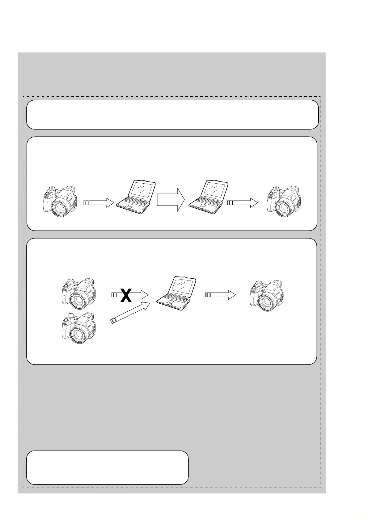
Procedure 1
Save the EVR data of the machine in which a board is going to be replaced. Download the sa ved data after a board
is replaced.
SECTION 6
ADJUSTMENTS
^
(Machine before starting repair)
Save the EVR data
to a personal computer.
Procedure 2
When the data cannot be saved due to defective flash memory, or when the flash memory cannot be removed or
installed, save the data from the same model of the same destination, and download it.
(Machine to be repaired)
PC
Save the data.
PC
Download the saved
data to a machine.
Download the data.
(Machine after a board is replaced)
(Machine to be repaired)PC
(The same model of the same destination)
After the EVR data is saved and downloaded, check the
respective items of the EVR data.
(Refer to page 6-3 for the items to be checked.)
DSC-H1
— 2 —
Page 3

& : Points added portion.
Precaution on Replacing the SY-127 board
• The Repair Board has already been adjusted. Re-initialization or EVR data copy from the set before repair is not
required.
• Perform “VIDEO OUT Default Data Check” mentioned below , and also the adjustment items necessary after SY Board
replacement.
VIDEO OUT Default Data Check
When you replace to the repairing board, the written data of repairing board also might be changed to original setteing
because of broadcast system (NTSC/PAL).
When the data has changed because of board replaceing etc, check the default data of VIDEO OUT if destination code is
right. If not, rewrite to the right value.
VIDEO OUT Default Data
Page Address
4F 8D 00 01
4F A2 00 01
+
Data
NTSC PAL
Writing Method:
1) Select page: 00, address: 01 and set data: 01.
2) Select page: 4F, address: 8D, and set data: 00 (NTSC) or data: 01 (PAL).
3) Select page: 4F, address: A2, and set data: 00 (NTSC) or data: 01 (PAL).
4) Select page: 40, address: 38, and set data: 00.
5) Click [Save] on the SEUS screen.
6) Wait for more than 3 sec.
7) Select page: 80, address: 30, and check that the data is “00”.
8) Select page: 00, address: 01, and set data: 00.
DSC-H1
— 3 —
Page 4

! : Points deleted portion.
1-1. Adjusting items when replacing main parts and boards
(Service Manual Page 6-3)
When replacing main parts and boards, adjust the items indicated by z in the following table.
Note 1: The automatic Adjustment Program does not support the “Initialization of data” and “Wide Limit Adjustment”. Perform them
manually.
Note 2: Use the AWB Adjustment Program (H1AwbAdjustment.exe).
Note 3: When replacing the SY-127 board, erase the data in internal memory of the board before replacement.
Note 4: When replacing the SY-127 board or the IC381 on the SY-127 board, execute formatting and initialize the internal memory after
replacement.
Replaced parts
Block Mounted parts Board
replacement replacement replacement
Adjusting item Adjustment
(Note 1) Initialization of data
VIDEO adjustment Video output level adj.
(Note 1) Wide limit adj.
CAMERA adjustment 1 Flange back adj.
CAMERA adjustment 2 Flange back check
F No. compensation
CAMERA adjustment 3
(Note 2) AWB 3200K-5800K standard data input
CAMERA adjustment 4
CAMERA adjustment 5
CAMERA adjustment 6
LCD adjustment
EVF adjustment White Balance adj.
Measure gain adj.
Mechanical shutter adj.
Light value adj.
Color reproduction adj. & check
CCD linearity check
CCD white defect compensation check
CCD black defect compensation check
Strobe adj.
Auto focus illumination check
HALL sensor gain adj.
Angular velocity sensor sensitivity adj.
V-COM adj.
White Balance adj.
LCD unit
Back light unit
LCD unit
(AF illumination LED)
(CCD imager)
(Timing gen., CCD signal process)
(EVF back light)
(Camera DSP)
(32M AND flash) (Note 4)
(LCD/EVF driver)
(Video amp.)
(PITCH, Y A W sensor)
LCD901
LED901
LCD902
D001
IC101
IC101
D001
IC301
IC381
IC601
IC802
SE401, 402
(COMPLETE)
(COMPLETE)
(COMPLETE)
(COMPLETE)
(COMPLETE) (Note 3, 4)
(COMPLETE)
Lens block
Flash unit
LCD block
LCD block
EVF block
AF-102 board
CD-576 board
CH-169 board
EV-016 board
SY-127 board
SY-127 board
SY-127 board
SY-127 board
SW-447 board
AF-102 board
CD-576 board
CH-169 board
EV-016 board
SY-127 board
SW-447 board
z
@
zz z
zz
zz zz
zz zz
z
zz
zzz
zzz zzz
z
zzz
z
z
z
z
z
zzz
z
z
z
z
z
z
z
z
zz
zz
zzzz zz
DSC-H1
Table 6-1-1
— 4 —
Page 5

: Points changed portion.
6-1. CAMERA SECTION ADJUSTMENTS
1-1. PREPARATIONS BEFORE ADJUSTMENTS
1-1-1. List of Service Tools
(Service Manual Page 6-4)
J-12
AC power adaptor
AC-LS5
1-479-284-12
Fig. 6-1-1
1-1-2. Preparations
(Service Manual Page 6-5)
AC power adaptor
AC-LS5
(1-479-284-12)
Note: Do not connect the A/V cable when
perfoming the LCD Adjustment and
EVF Adjustment.
To AV OUT jack (Note)
AC IN
PC
(The SEUS must be installed in the PC.)
OS: Windows 98/98SE/Me/2000/XP
RAM: 256MB or more recommended
USB: 2.0 recommended (also compatible with 1.1)
Two connectors are required.
Insert the connection cord
DK-2AA (1-830-351-11).
To USB connector
HASP Key
VIDEO Adjustment and
CAMERA Adjustment 6
Osilloscope
Terminated
75 Ω
To USB
connector
USB cable
(1-827-038-11)
Audio (Black)
Color monitor
Video (yellow)
DSC-H1
Fig. 6-1-4
— 5 —
 Loading...