

Page 1

DSC-H1
Ver. 1.3 2007.08
Revision History
Revision History
Link
Link
Before starting adjustments
Before starting adjustments
Adjusting items when replacing main parts and boards
Adjusting items when replacing main parts and boards
CAMERA SECTION ADJUSTMENTS
CAMERA SECTION ADJUSTMENTS
PREPARATIONS BEFORE ADJUSTMENTS
PREPARATIONS BEFORE ADJUSTMENTS
ADJUSTMENT PROGRAMS
ADJUSTMENT PROGRAMS
VIDEO SYSTEM ADJUSTMENTS
VIDEO SYSTEM ADJUSTMENTS
CAMERA SYSTEM ADJUSTMENTS
CAMERA SYSTEM ADJUSTMENTS
LCD SYSTEM ADJUSTMENTS
LCD SYSTEM ADJUSTMENTS
EVF SYSTEM ADJUSTMENTS
EVF SYSTEM ADJUSTMENTS
SECTION 6
ADJUSTMENTS
SERVICE MODE
SERVICE MODE
SERVICE MODE
SERVICE MODE
Auto-ADJ
ERROR
ERROR
INITIALIZATION OF DATA
INITIALIZATION OF DATA
• Use this Service Manual together with the Automatic Adjustment Program (DSC-H1 Auto-Adj Ver_1.3r03.exe)
and the AWB Adjustment Program (H1AwbAdjustment.exe).
DSC-H1
9-876-880-52
Sony EMCS Co.
2007H0500-1
© 2007.8
Published by Kohda TEC
Page 2

TABLE OF CONTENTS
Section Title Page
6. ADJUSTMENTS
Before Starting Adjustment ·······················································6-1
1-1. Adjusting Items When Replacing
Main Parts and Boards ····················································6-3
6-1. Camera Section Adjustments···········································6-4
1-1. Preparations Before Adjustments ····································6-4
1-2. Adjustment Programs ······················································6-9
1-3. Video System Adjustments············································ 6-11
1-4. Camera System Adjustments·········································6-13
1-5. LCD System Adjustments ·············································6-24
1-6. EVF System Adjustments··············································6-26
1-7. Error···············································································6-27
1-8. Initialization of Data······················································ 6-29
6-2. Service Mode································································· 6-30
DSC-H1
— 2 —
Page 3
Ver 1.1 2005.11
Before starting adjustment
Precaution on Replacing the SY-127 board
• The Repair Board has already been adjusted. Re-initialization or EVR data copy from the set before repair is not
required.
• Perform “VIDEO OUT Default Data Check” mentioned below, and also the adjustment items necessary after SY
Board replacement.
VIDEO OUT Default Data Check
When you replace to the repairing board, the written data of repairing board also might be changed to original setteing
because of broadcast system (NTSC/PAL).
When the data has changed because of board replaceing etc, check the default data of VIDEO OUT if destination code
is right. If not, rewrite to the right value.
VIDEO OUT Default Data
Page Address
4F 8D 00 01
4F A2 00 01
SECTION 6
ADJUSTMENTS
Data
NTSC PAL
Writing Method:
1) Select page: 00, address: 01 and set data: 01.
2) Select page: 4F, address: 8D, and set data: 00 (NTSC) or data: 01 (PAL).
3) Select page: 4F, address: A2, and set data: 00 (NTSC) or data: 01 (PAL).
4) Select page: 40, address: 38, and set data: 00.
5) Click [Save] on the SEUS screen.
6) Wait for more than 3 sec.
7) Select page: 80, address: 30, and check that the data is “00”.
8) Select page: 00, address: 01, and set data: 00.
DSC-H1
6-1
Page 4

Method for Copying or Erasing the Data in Internal Memory
The data can be copied/erased by the operations on the Setup screen. (When erasing the data, execute formatting the
internal memory.)
Note 1: When replacing the SY-127 board, erase the data in internal memory of the board before replacement.
Note 2: When replacing the SY-127 board or the IC381 on the SY-127 board, execute formatting and initialize the
internal memory after replacement.
Method for copying the data in internal memory
Copy
Copies all images in the internal memory to a “Memory Stick”.
OK
Cancel
1 Insert a “Memory Stick ” having 32 MB or larger capacity.
2 Select [OK] with v on the control button, then press z.
The message “All data in internal memory will be copied Ready?” appears.
3 Select [OK] with v, then press z.
Copying starts.
Copying
102_COPY
•Use fully charged Nickel-Metal Hydride batteries or the AC Adaptor (not supplied). If you attempt to
copy image files using batteries with little remaining charge, the batteries may run out, causing copying to
fail or possibly corrupting the data.
•You cannot copy individual images.
•The original images in the internal memory are retained even after copying. To delete the contents of the
internal memory, remove the “Memory Stick” after copying, then execute the [Format] command in
Internal Memory Tool.
•You cannot select a folder copied on a “Memory Stick”.
•The setting of (Print order) marks is not copied even when you copy data.
See the following procedure.
Cancels the copying.
Method for formatting the internal memory
This item does not appear when a “Memory Stick” is inserted in the camera.
The default se ttings are marked with .
Format
Formats the internal memory.
Note that formatting irrevocably erases all data in the internal memo ry, including even protected images.
OK
Cancel
1 Select [OK] with v on the control button, then press z.
The message “All data in intern al mem or y will be eras ed Ready ?” ap pears .
2 Select [OK] with v, the n pr es s z.
The format is complete.
See the following procedure.
Cancels the formatting.
DSC-H1
6-2
Page 5
Ver 1.1 2005.11
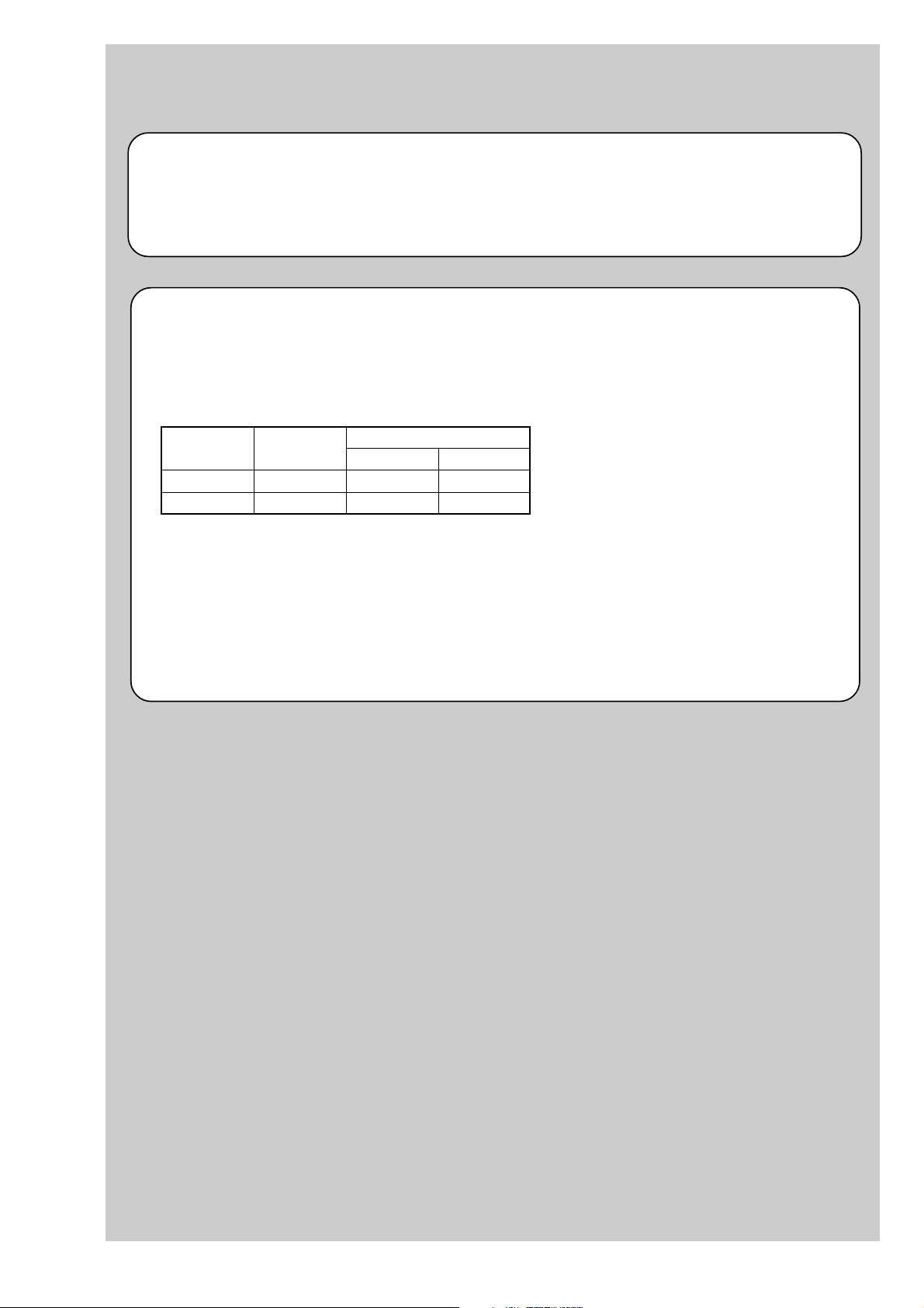
1-1. Adjusting items when replacing main parts and boards
When replacing main parts and boards, adjust the items indicated by z in the following table.
Note 1: The automatic Adjustment Program does not support the “Initialization of data” and “Wide Limit Adjustment”. Perform them
manually.
Note 2: Use the AWB Adjustment Program (H1AwbAdjustment.exe).
Note 3: When replacing the SY-127 board, erase the data in internal memory of the board before replacement.
Note 4: When replacing the SY-127 board or the IC381 on the SY-127 board, execute formatting and initialize the internal memory after
replacement.
Replaced parts
Block Mounted parts Board
replacement replacement replacement
Adjusting item Adjustment
(Note 1) Initialization of data
VIDEO adjustment Video output level adj.
(Note 1) Wide limit adj.
CAMERA adjustment 1 Flange back adj.
CAMERA adjustment 2 Flange back check
F No. compensation
CAMERA adjustment 3
(Note 2) AWB 3200K-5800K standard data input
CAMERA adjustment 4
CAMERA adjustment 5
CAMERA adjustment 6
LCD adjustment
EVF adjustment White Balance adj.
Measure gain adj.
Mechanical shutter adj.
Light value adj.
Color reproduction adj. & check
CCD linearity check
CCD white defect compensation check
CCD black defect compensation check
Strobe adj.
Auto focus illumination check
HALL sensor gain adj.
Angular velocity sensor sensitivity adj.
V-COM adj.
White Balance adj.
LCD unit
Back light unit
LCD unit
(AF illumination LED)
(CCD imager)
(Timing gen., CCD signal process)
(EVF back light)
(Camera DSP)
(32M AND flash) (Note 4)
(LCD/EVF driver)
(Video amp.)
(PITCH, YAW sensor)
LCD901
LED901
LCD902
D001
IC101
IC101
D001
IC301
IC381
IC601
IC802
SE401, 402
(COMPLETE)
(COMPLETE)
(COMPLETE)
(COMPLETE)
(COMPLETE) (Note 3, 4)
(COMPLETE)
Lens block
Flash unit
LCD block
LCD block
EVF block
AF-102 board
CD-576 board
CH-169 board
EV-016 board
SY-127 board
SY-127 board
SY-127 board
SY-127 board
SW-447 board
AF-102 board
CD-576 board
CH-169 board
EV-016 board
SY-127 board
SW-447 board
zz z
zz
zz zz
zz zz
z
zz
zzz
zzz zzz
z
z
zzzzz
z
z
z
z
z
z
z
z
z
z
z
z
z
zz
zz
zzzz zz
DSC-H1
Table 6-1-1
6-3
Page 6
6-1. CAMERA SECTION ADJUSTMENTS
1-1. PREPARATIONS BEFORE ADJUSTMENTS
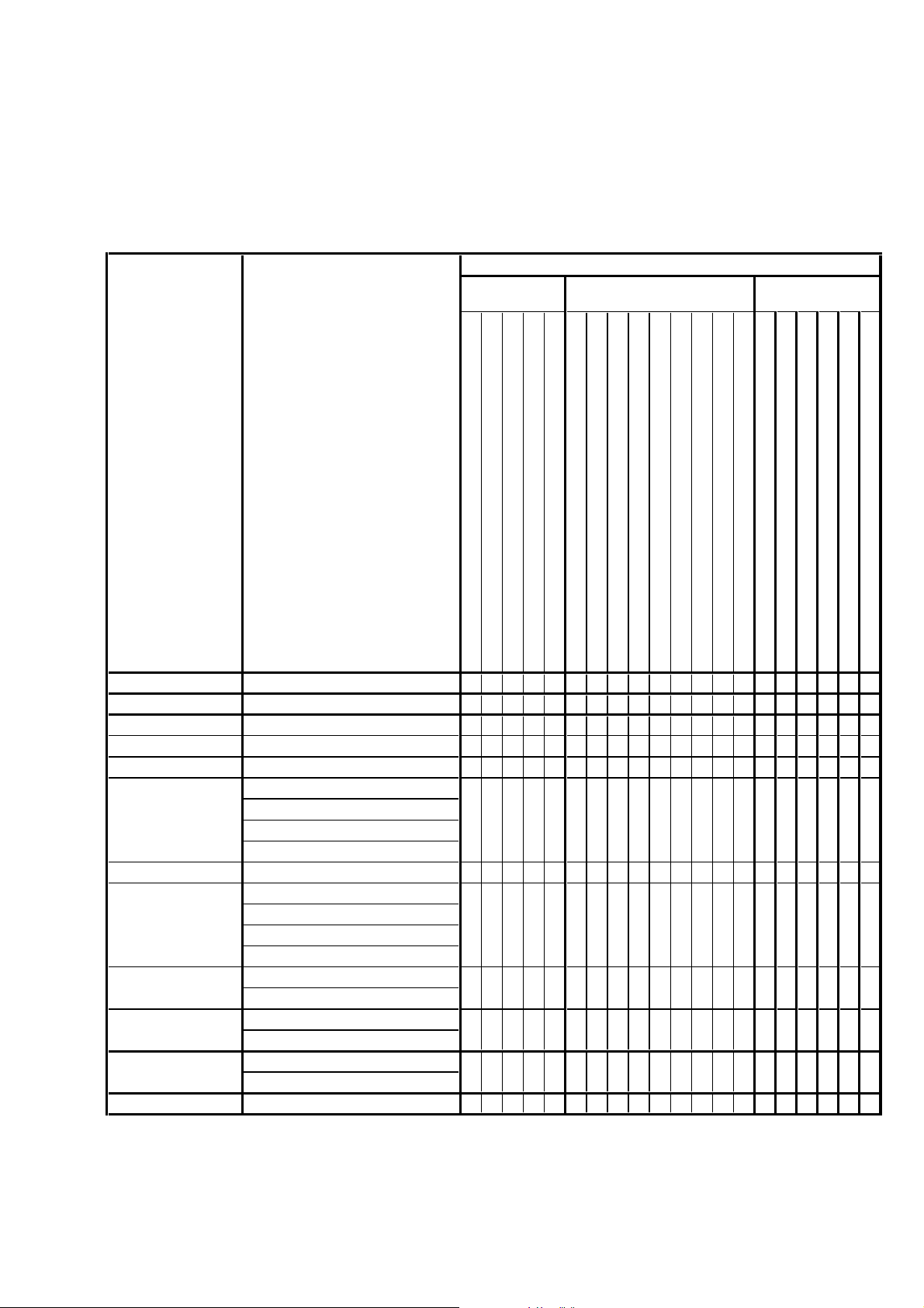
1-1-1. List of Service Tools
• Oscilloscope • Color monitor
Ver 1.1 2005.11
J-1
J-4
J-7
J-10
Personal computer
(Note 1)
Pattern box PTB-450
J-6082-200-A
or
Small pattern box
PTB-1450
J-6082-557-A
Minipattern box
J-6082-353-B
J-2
HASP key and application
for adjustment (SEUS)
Contact our service headquater of each area
how to get the application for adjustment
(SEUS) and HASP key.
J-5
9 colors chart (Note 2)
For PTB-1450:
J-6082-562-A
J-8
Flange back
adjustment jig
J-6082-563-A
J-11
J-3
USB cable
1-827-038-11
J-6
Clear chart
For PTB-450:
J-6080-621-A
For PTB-1450:
J-6082-560-A
J-9
Siemens star chart
J-6080-875-A
J-12
Back ground paper
J-2501-130-A
Connection code
DK-2AA
1-830-351-11
AC power adaptor
AC-LS5
1-479-284-12
Fig. 6-1-1
Note1: Personal computer
OS: Windows98/98SE/Me/2000/XP Home/XP Pro
RAM: 256MB or more recommended
USB: 2.0 recommended (also compatible with 1.1)
Two connectors are required.
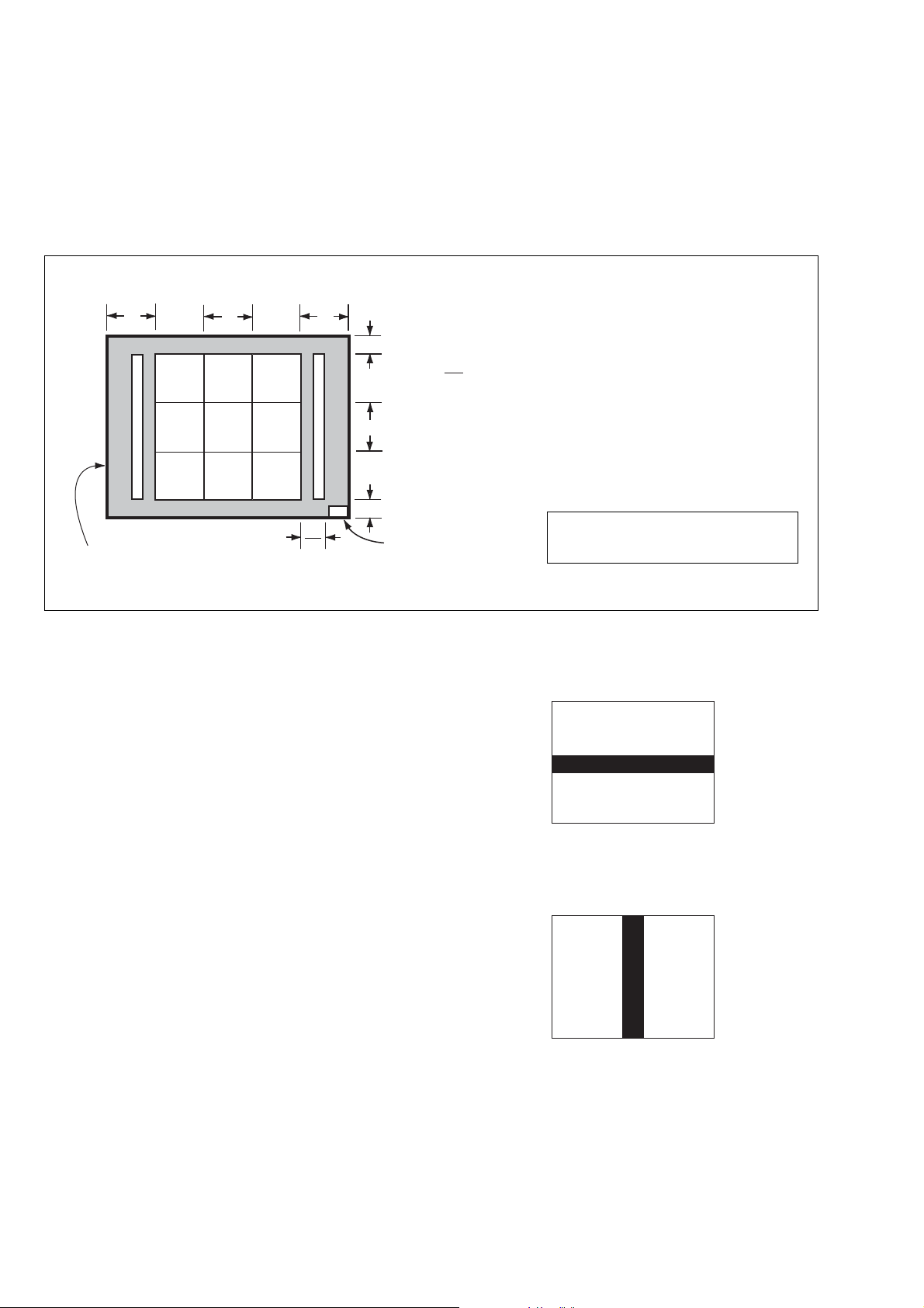
Note2: In using the 9 colors chart on the pattern box PTB-450, adjust the chart size through the procedure shown below so that it matches
to the pattern box PTB-450.
1) Prepare a woody board A of the thickness 5 mm, and paint it mat-black.
2) Fit the 9 colors chart in the woody board A, and secure the chart with a black tape, etc. to shield the light.
woody boad A
360 mm
155 mm
135 mm
280 mm
woody boad A
DSC-H1
9 colors chart
Fig. 6-1-2
6-4
Page 7
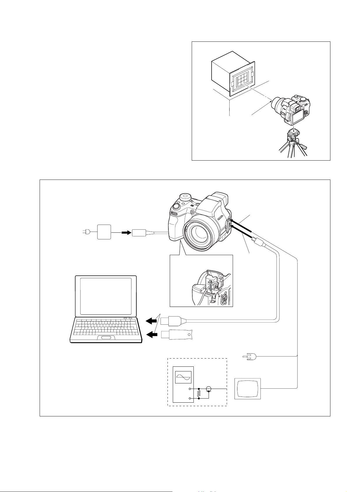
PC
(The SEUS must be installed in the PC.)
OS: Windows 98/98SE/Me/2000/XP
RAM: 256MB or more recommended
USB: 2.0 recommended (also compatible with 1.1)
Two connectors are required.
VIDEO Adjustment and
CAMERA Adjustment 6
Osilloscope
Terminated
75 Ω
AC IN
Insert the connection cord
DK-2AA (1-830-351-11).
To USB
connector
To AV OUT jack (Note)
Note: Do not connect the A/V cable when
perfoming the LCD Adjustment and
EVF Adjustment.
HASP Key
To USB connector
USB cable
(1-827-038-11)
Audio (Black)
Video (yellow)
Color monitor
AC power adaptor
AC-LS5
(1-479-284-12)
Ver 1.1 2005.11
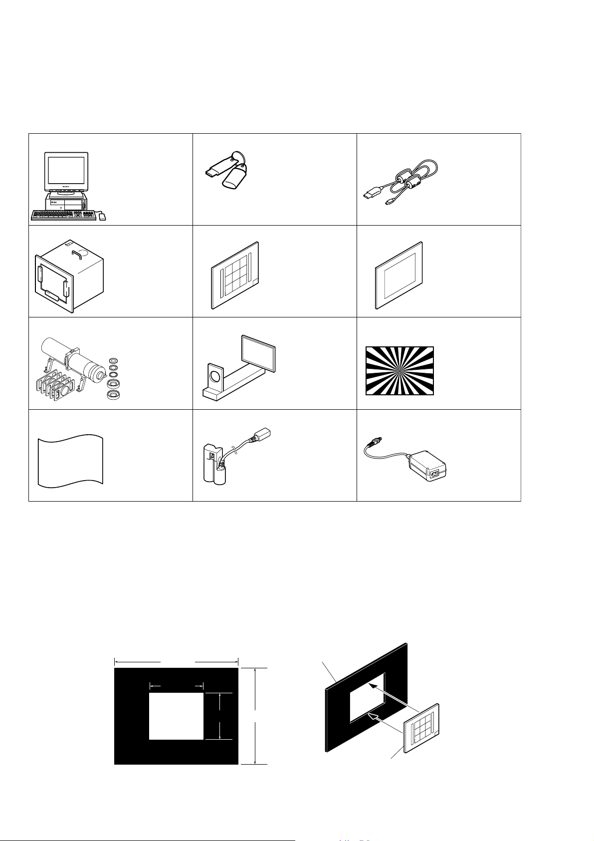
1-1-2. Preparations
1) Connect the equipment for adjustments according to Fig. 6-1-4.
2) Start up the application for adjustment (SEUS).
Pattern box
L
Front of the lens
L = About 9 cm
Fig. 6-1-3
Fig. 6-1-4
DSC-H1
6-5
Page 8
1-1-3. Precautions
White
White
Black
A4 size (297 mm × 210 mm)
Pattern A
Black
White
White
Black
A4 size (297 mm × 210 mm)
Pattern B
Black
1. Setting the Switch
Unless otherwise specified, set the switches as follows and perform adjustments.
1. Mode Dial .......................................... CAMERA (Auto)
2. ZOOM button..................................... WIDE end
3. Video Out (SET UP setting).............. NTSC
4. Digital Zoom (SET UP setting)......... Off
9 colors chart (Standard picture frame)
A
Green
C14 Blue
Effective picture frame
Fig. a LCD screen or under scan
( )
BA
Yellow
WhiteCyan
monitor TV picture
W14
Red
Magenta
A
2
2. Subjects
1) 9 colors chart (Standard picture frame).
When performing adjustments using the 9 colors chart, adjust
the picture frame as shown in Fig. 6-1-5. (Standard picture
frame)
2) Clear chart (Standard picture frame)
Remove the 9 colors chart from the pattern box and insert a
clear chart in its place. (Do not perform zoom operations during this time)
3) Chart for CAMERA Adjustment 6
Combining A4-sized white and black sheets, create two types
of charts (Pattern A and P attern B) as sho wn in Fig. 6-1-6 and
Fig. 6-1-7.
C
B
C
A = B
C =
C14: Filter for AWB 5800K adjustment
Transparent window
Fig. 6-1-5
B
3
Adjust the camera position and direction
to obtain the LCD screen or the monitor
TV display shown in Fig. a.
Fig. 6-1-6
DSC-H1
Fig. 6-1-7
6-6
Page 9
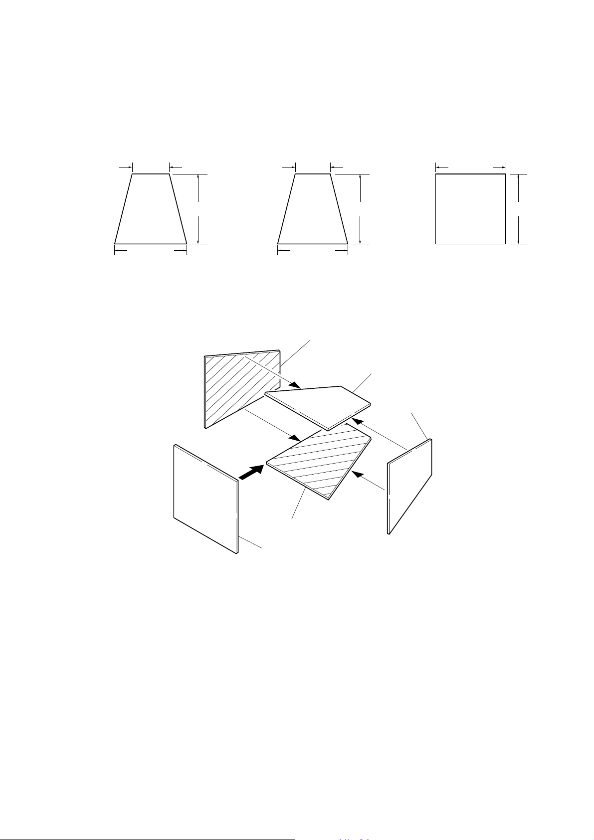
3. Preparing the Flash Adjustment Box
A dark room is required to provide an accurate flash adjustment.
If it is not available, prepare the flash adjustment box as given
below;
1) Provide woody board A, B and C of 15 mm thickness.
woody board A (2)
400 mm
513 mm 513 mm 700 mm
woody board B (2)
Fig. 6-1-8
2) Apply black mat paint to one side of woody board A and B.
3) Attach background paper (J-2501-130-A) to woody board C.
4) Assemble so that the black sides and the background paper
side of woody board A, B and C are internal. (Fig. 6-1-9)
370 mm
700 mm730 mm
woody board A
woody board C (1)
700 mm
woody board B
woody board A
DSC-H1
woody board B
woody board C
Fig. 6-1-9
6-7
Page 10
1-1-4. Using Method of SEUS
The application for adjustment (SEUS) is used to change the coefficient for calculating the signal processing or EVR data. The SEUS
performs two-way communication between PC and set through
the USB terminal. The two-way communication result data can be
written to the nonvolatile memory.
1. Connection
1) Connect the HASP key to the USB terminal of the PC.
2) Connect the PC and set with the USB cable.
3) Confirm that the set starts in the USB mode.
4) Start the SEUS on the PC.
5) Click [Connect] on the SEUS screen. If the connection is nor-
mal, the SEUS screen will be as shown in Fig. 6-1-10, indicating the “connected” state.
Note: The SEUS will go in “disconnect" state, if the set is
turned off (for instance, by resetting the set). In such a
case, click [Connect] on the SEUS screen to restore the
“connected” state.
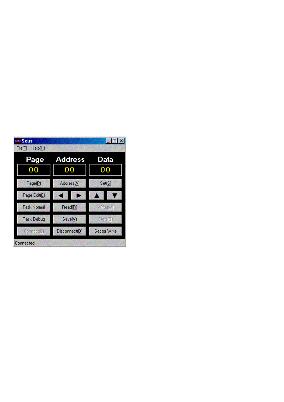
2. Operation
• Page change
To change the page, click [Page] on the SEUS screen and enter
the page to be changed. The page is displayed in hexadecimal
notation.
• Address change
To change the address, click [Address] on the SEUS screen and
enter the address to be changed. The address is displayed in
hexadecimal notation.
• Data change
To change the data, click [Set] on the SEUS screen and enter the
data. The data is displayed in hexadecimal notation.
This operation does not write the data to the nonv olatile memory .
• Data saving
To write the all changed data to the nonvolatile memory, click
[Save] on the SEUS screen and wait for more than 3 sec.
• Data reading
The data displayed on the SEUS screen are the data values at
the time when the pages and addresses were set, and they are
not updated automatically. T o check the data change, click [Read]
on the SEUS screen and update the displayed data.
1-1-5. Precaution on Use of SEUS
Wrong SEUS operation could clear correct adjustment data. To
prevent the data clear by mistake, it is recommended to save all
adjustment data by clicking [Page Edit] on the SEUS screen before starting the adjustment.
Fig. 6-1-10
Saving Method:
1) Click [Page Edit] on the SEUS screen to display the SEUS
PAGE EDIT screen.
2) Click [Page], and enter the page number to be saved.
3) Click [Read] to read the data to be saved from the camera.
4) Click [File] and save the data to PC.
Loading Method:
1) Select page: 00, address: 01 and set data: 01.
2) Click [Page Edit] on the SEUS screen to display the SEUS
PAGE EDIT screen.
3) Click [File] and load the data from PC.
4) Click [Write] on the SEUS PAGE EDIT screen.
5) Click [Close] to close the SEUS PAGE EDIT screen.
6) Select page: 40, address: 38 and set data: 00.
7) Click [Save] on the SEUS screen.
8) Wait for more than 3 sec.
9) Select page: 80, address: 30, and check that the data is “00”.
10) Select page: 00, address: 01 and set data: 00.
DSC-H1
6-8
Page 11

3
2
1
4
7
6
5
Ver. 1.2 2007.07
1-2. ADJUSTMENT PROGRAMS
The DSC-H1 is adjusted with the Automatic Adjustment Program
and the AWB Adjustment Program.
The Automatic Adjustment Program automatically controls the
adjustment operations that were formerly entered manually on the
operation screen of the SEUS (some adjustments may be manually operated on the SEUS operation screen).
The AWB Adjustment Program automatically performs “AWB
3200K-5800K Standard Data Input” of Camera System Adjustment.
1-2-1. Automatic Adjustment Program
1. Precautions When Using Automatic Adjustment
Program
1) The Automatic Adjustment Program writes the adjustment r e-
sults such as EVR data to the set through two-way communication with the camera via the SEUS. Accordingly, the Automatic Adjustment Program must be used in the environment
where the SEUS operates.
2) The program run time may vary depending on the environ-
ment of the personal computer used.
3) Even if the Automatic Adjustment Program is used without
starting the SEUS, the SEUS will start automatically when the
adjustment is executed. Howe ver, it may take time for the SEUS
to start, and therefore the Automatic Adjustment Program
should be used with the SEUS started in order to reduce the
program run time.
2. Start of Automatic Adjustment Program
Double-click the application file (DSC-H1 Auto-Adj Ver_1.2r02.exe),
and the Automatic Adjustment Program will start.
3. Function of Each Button on Main Menu Screen
When the Automatic Adjustment Program started, the Main Menu
screen in Fig. 6-1-11 will appear. On this screen, select each adjustment section.
Fig. 6-1-11
1 [Connecting the Equipment] button
A connection diagram of the equipment is displayed.
2 [VIDEO SYSTEM ADJUSTMENT] button
The “VIDEO SYSTEM ADJUSTMENT” screen appears.
3 [CAMERA SYSTEM ADJUSTMENT] button
The “CAMERA SYSTEM ADJUSTMENT” screen appears.
4 [LCD SYSTEM ADJUSTMENT] button
The “LCD SYSTEM ADJUSTMENT” screen appears.
5 [EVF SYSTEM ADJUSTMENT] button
The “EVF SYSTEM ADJUSTMENT” screen appears.
6 [END] button
The Automatic Adjustment Program finishes.
7 This part indicates the version of Automatic Adjustment Pro-
gram.
DSC-H1
6-9
Page 12

1-2-2. AWB Adjustment Program
1. Application Environment
OS: Windows 98/98SE/Me/2000/XP
RAM: 256MB or more recommended
USB: 2.0 recommended (also compatible with 1.1)
Two connectors are required.
2. Installation Method
Extract the file compressed in the ZIP format (H1AWBAdjustment.zip).
Execute the extracted file (setup.exe), and the installer will start.
Install the program following the instructions given on the installer
screen.
3. Notes When Using the AWB Adjustment Program
1) The SEUS must be installed in the PC.
2) The HASP Key for SEUS must be connected to the USB connector. The program will not start unless the HASP Key is
connected.
4. Starting Method of AWB Adjustment Program
Click the [Start] button on the task bar , and click the [DSC-H1 AWB
Adjustment] from the [Programs], and the program will start.
5. Screen and Function of Each Button of AWB
Adjustment Program
4
1
2
3
A
Fig. 6-1-12
1 [Connect] button
Makes connection to the camera and switches the camera to
the adjustment mode. In the case of successful connection to
the camera, the indication at the part A changes to “Connected”
and the following buttons become active.
• [AWB 3200K-5800K Standard Data Input] button
• [Disconnect] button
2 Adjustment start buttons
Start the adjustment or checking of respective button names.
3 [Disconnect] button
Cancels the connection to the camera.
4 Captured picture display screen
Displays a picture captured by the camera when the adjustment or checking was performed.
DSC-H1
6-10
Page 13

1-3. VIDEO SYSTEM ADJUSTMENTS
1-3-1. Function of Each Button on Video System
Adjustment Screen
Click the [VIDEO SYSTEM ADJUSTMENT] button on the Main Menu
screen, and the “VIDEO SYSTEM ADJUSTMENT” screen in Fig.
6-1-13 will appear.
1
1-3-2. Adjustment Items of VIDEO System
Adjustment
The adjustment items of video system adjustment are as listed in
Table 6-1-2. The Automatic Adjustment Program e xecutes the adjustment items if the VIDEO Adjustment Start button is clicked.
Button
Name
VIDEO VIDEO Output
Adjustment Level Adj.
Adjustment Signal Page Address
Arbitrary 8F D0
Table 6-1-2
2
5
3
4
Fig. 6-1-13
1 [To Menu] button
The Main Menu screen comes back.
2 [Preparation] button
Notes for adjustment or jigs usd are displayed.
3 [Start] button
“Video Adjustment” starts.
4 [Reset] button
This button functions same as the “Initialize” of the setup
screen.
5 [Release Data Setting] button
The data setting at the adjustment is cancelled.
During the data setting, the button color changes from “white”
to “red”. When the data setting is cancelled, the button color
returns to “white”.
(Use this button when an error occurred in the video adjustment. If the adjustment completed successfully, the data setting is automatically cancelled and the button color returns to
“white”.)
DSC-H1
6-11
Page 14

1-3-3. Adjusting Method
[Automatic Adjustment Program execution items and
sequence]
1. Data Setting during Video Adj.
2. Video Output Level Adj.
3. Release of Data Setting during Video Adj.
[Specified value of video output level adj.]
Measurement Point Video terminal of A/V OUT jack
(75 Ω terminated)
Measuring Instrument Oscilloscope
Specified Value Sync level:
A = 286 ± 5 mV (NTSC mode)
A = 300 ± 5 mV (PAL mode)
Burst level:
B = 286 ± 25 mV (NTSC mode)
B = 300 ± 25 mV (PAL mode)
[Adjusting method]
1) Click the [Start] button of the VIDEO Adjustment.
2) The Automatic Adjustment Program executes the “1. Data Setting during Video Adj.”.
3) If “1. Data Setting during V ideo Adj.” completed successfully ,
the next message is displayed during the execution of “2. V ideo
Output Level Adj.”. Using the UP/DOWN key on the SEUS
Operation screen, adjust so that the sync level of the video
signals satisfies the specified value. After the adjustment, check
that the burst level of the video signals satisfies the specified
value, and click the [OK] button in the message.
SEUS operation screen
UP/DOWN key
Fig. 6-1-16
Check on the oscilloscope
B
A
Fig. 6-1-14
4) If the [OK] button button is clicked, “3. Release of Data Set-
ting during Video Adj.” will be executed.
5) Upon successful completion of all items of the VIDEO Adjustment, the following message is displayed. Click the [OK]
button.
Fig. 6-1-15
H
Fig. 6-1-17
DSC-H1
6-12
Page 15

1-4. CAMERA SYSTEM ADJUSTMENTS
1-4-1. Function of Each Button on Camera System
Adjustment Screen
Click the [CAMERA SYSTEM ADJUSTMENT] button on the Main
Menu screen, and the “CAMERA SYSTEM ADJUSTMENT”
screen in Fig. 6-1-18 will appear.
1
2
3
3
2
4
6
Fig. 6-1-18
1 [To Menu] button
The Main Menu screen comes back.
2 [Preparation] button
Notes for adjustment or jigs used are displayed.
3 [Start] button
Each adjustment from “Camera Adjustment 1” to “Camera
Adjustment 6” starts.
4 Mode Select radio button
Selects the mode to be adjusted.
5 [Reset] button
This button functions same as the “Initialize” of the setup
screen.
6 [Release Data Setting] button
The data setting at the adjustment is cancelled.
During the data setting, the button color changes from “white”
to “red”. When the data setting is cancelled, the button color
returns to “white”.
(Use this button when an error occurred in the camera adjustment 1-6. If the adjustment completed successfully, the data
setting is automatically cancelled and the button color returns
to “white”.)
5
DSC-H1
6-13
Page 16

1-4-2. Adjustment Items of Camera System Adjust-
ment
The adjustment items of camera system adjustment are as listed in
Table 6-1-3. The Automatic Adjustment Program divides the adjustment items into six, camera adjustment 1-6. Clicking either
CAMERA Adjustment Start button allows the adjustment item
which corresponds to that button to be executed.
The adjustment conditions of the subject and filter vary depending on which item is adjusted. The Adjustment Program displays
an instruction for the subject and filter as a message during the
adjustment.
Button Name Adjustment Subject
(Note 1) Wide Limit Adj. Not required 6F 18, 19
Siemens star chart with ND filter
CAMERA Adjustment 1 Flange Back Adj. for minipattern box (Note 2) or
Flange back adjustment jig
Siemens star
CAMERA Adjustment 2 Flange Back Check (1.0m from front the lens)
(Luminance: 200 to 400 lux)
F No. Compensation 6F 60 to 63, 6B to 6D
Measure Gain Adj.
CAMERA Adjustment 3
Mechanical Shutter Adj.
Light Value Adj.
(Note 3)
CAMERA Adjustment 4 CCD White Defect
CAMERA Adjustment 5 Flash adjustment box (50 cm) 6F D8 to EF
CAMERA Adjustment 6
Note 1: The Automatic Adjustment Program does not support the “Wide Limit Adjustment”.
Note 2: Dark Siemens star chart.
Note 3: Use the AWB Adjustment Program (H1AwbAdjustment.exe).
AWB 3200K-5800K 9 colors chart
Standard Data Input (Standard picture frame)
Color Reproduction 9 colors chart
Adj. & Check (Standard picture frame)
CCD Linearity Check
Compensation Check
CCD Black Defect
Compensation Check
Strobe Adj.
Auto focus illumination Check 6F 10 to 15
HALL Sensor Gain Adj. Pattern A
(Vertical) (1.5 m from front the lens)
HALL Sensor Gain Adj. Pattern B
(Horizontal) (1.5 m from front the lens)
Angular V elocity Sensor
Sensitivity Adj.
Clear chart
(Standard picture frame)
Clear chart
(Standard picture frame)
Not required CF 0B, 0C
Adjustment Adjustment
Page Address
6D A4 to AF, D0 to F7
6F 18 to 3F, 52, 53
__
6F 6B, 6F
78 0C to 0F
6F
79
6F 65 to 67
6E 00 to 21, 24 to 49
6E 60 to 67
_ _
__
__
6E 72 to 75
CF 09
CF 0A
6B to 6D, B8 to BD,
C7 to C9
40 to 42, 45 to 47,
4A
DSC-H1
Table 6-1-3
6-14
Page 17

1-4-3. Adjusting Method
1. Wide Limit Adjustment
Adjustment to remove variations at the wide end of the inner focus lens.
Adjustment Page 6F
Adjustment Address 18, 19
1-1. Adjusting method when the lens is replaced:
Adjusting method:
Order Page
1000101 Set the data.
2403800 Set the data.
36F18 Set the data. (Note)
46F19 Set the data. (Note)
57C1601 t 00 Change the data.
6Save the data.
7Wait for 2 sec.
8 Perform “Flange Back
Note: The data of page: 6F, address: 18 and 19, that are set in the
Orders 2 and 3 as described above, are shown on the data
sheet supplied with the replacement lens for repair.
Set the upper single byte of the 2-byte data shown on the
sheet to address: 18, and the lower byte of the data to the
address: 19.
Address
Data Procedure
(The data is OK if it is “00”.)
Adjustment”.
1-2. Adjusting method when replacement of lens is
not required and the SY-127 board is replaced:
When the data of page: 6F, address: 18 and 19 can be
read from the defective SY-127 board before replacement, and both of the data are not “00”:
Adjusting method:
Order Page
1000101 Set the data.
2403800 Set the data.
36F18 Set the previous data
46F19 Set the previous data
57C1601 t 00 Change the data.
6Save the data.
7Wait for 2 sec.
8 Perform “Flange Back
When the data of the page: 6F, address: 18 and 19 can
be read out from the defective SY-127 board before replacing it, and both of the data are “00”:
1) Replace the lens with the replacement lens and perform “1-1.
Adjusting method when the lens is replaced”.
Address
Data Procedure
(The data is OK if it is “00”.)
Adjustment”.
The right four digits of the seal (2-byte data)
XX XXXX
Data for Page: 6F, Address: 19
Data for Page: 6F, Address: 18
Fig. 6-1-19
When the data of page: 6F, address: 18 and 19 cannot be
read from the defective SY-127 board:
1) Replace the lens with the replacement lens and perform “1-1.
Adjusting method when the lens is replaced”.
Note: The data of page: 7C, address: 16, that is set in the Order 4
of the adjusting method of 1-1 or 1-2, is “01” when shipped
from the factory . Let the data remain “00” after completion
of the service adjustment.
DSC-H1
6-15
Page 18

2. CAMERA Adjustment 1
[Automatic Adjustment Program execution items and
sequence]
1. Data Setting during Camera Adj.
2. Flange Back Adj.
3. Release of Data Setting during Camera Adj.
[Adjusting method]
1) If the [Start] button of the CAMERA Adjustment 1 is click ed,
the following message is displayed.
If “Wide Limit Adjustment” is necessary, click the [Cancel]
button to interrupt the Adjustment Program, and perform “1.
Wide Limit Adjustment”.
Preparation of Flange Back Adj.
(Using the minipattern box)
1) The minipattern box is installed as shown in the following figure.
Note 1: The attachment lenses are not used.
Note 2: Take care not to hit the mini-pattern box when ex-
tending the lens.
2) Install the minipattern box so that the distance between it and
the front of lens of camera is less than 3 cm.
3) Make the height of minipattern box and the camera equal.
4) Check the output voltage of the regulated power supply is the
specified voltage ± 0.01 Vdc.
5) Check that the center of Siemens star chart meets the center of
shot image screen with the zoom lens at TELE end and WIDE
end respectively.
Specified voltage: The specified voltage varies according to the
minipattern box, so adjustment the power supply output voltage to the specified voltage written on the sheet which is supplied with the
minipattern box.
Below 3 cm
Fig. 6-1-20
2) If the [OK] button is clicked, the Automatic Adjustment Pro-
gram executes “1. Data Setting during Camera Adj.”.
3) Upon successful completion of the “1. Data Setting during
Camera Adj. ”, the follo wing message is displayed. Set the subject by referring to “Preparation of Flange Back Adj.”.
Fig. 6-1-21
4) If the [OK] button is clicked, “2. Flange Back Adj.” and “3.
Release of Data Setting during Camera Adj. ” will be e xecuted.
5) Upon successful completion of all items of the CAMERA
Adjustment 1, the following message is displayed. Click the
[OK] button.
Fig. 6-1-22
Minipattern box
Camera
Output voltage : Specified voltage ± 0.01 Vdc
Red (+)
Black (–)
Yellow (SENS +)
White (SENS –)
Black (GND)
Regulated power supply
Output current : more than 3.5 A
Need not connected
Fig. 6-1-23
Preparation of Flange Back Adj.
(Using the flange back adjustment jig)
(Luminance: about 300 lux)
1) Install the flange back adjustment jig so that the distance between it and the front of lens of camera is less than 3 cm.
Note 3: Take care not to hit the flange back adjustment jig
when extending the lens.
2) Make the height of flange back adjustment jig and the camera
equal.
3) Check that the center of chart meets the center of shot image
screen with the zoom lens at TELE end and WIDE end respectively.
Flange back adjustment jig
Below 3 cm
DSC-H1
Camera
Fig. 6-1-24
6-16
Page 19

3. CAMERA Adjustment 2
[Automatic Adjustment Program execution items and
sequence]
1. Data Setting during Camera Adj.
2. Flange Back Check
3. Release of Data Setting during Camera Adj.
[Adjusting method]
1) Click the [Start] button of the CAMERA Adjustment 2.
2) The Automatic Adjustment Program executes “1. Data Setting
during Camera Adj.”.
3) Upon successful completion of the “1. Data Setting during
Camera Adj.”, the following message is displayed. Set the subject in accordance with the message.
Fig. 6-1-25
4) Click the [OK] button is clicked, “2. Flange Back Check” is
executed. The following messages are displayed, and then operate the camera to make a check in accordance with the messages.
4. Picture Frame Setting (Standard Picture Frame)
In the “CAMERA Adjustment 3”, “A WB 3200K-5800K Standard
Data Input” and “CAMERA Adjustment 4”, set the picture frame
so as to attain the positions shown in the following figure when
shooting the 9 colors chart.
Check on the oscilloscope
Measurement Point:Video terminal of A/V OUT jack
(75Ω terminated)
1. Horizontal period
A = B
A
B
A
Fig. 6-1-28
Fig. 6-1-26
5) Upon completion of “2. Flange Back Check”, “3. Release of
Data Setting during Camera Adj.” is executed.
6) Upon successful completion of all items of the CAMERA
Adjustment 2, the following message is displayed. Click the
[OK] button.
2. Vertical period
B
V
C =
CC
B
3
Fig. 6-1-29
Check on the monitor TV or the LCD screen
B
C =A = B
3
C14: Filter for AWB 5800K adjustment
AAB
YellowGreen
WhiteCyan
BlueC14
W14
Red
Magenta
C
B
DSC-H1
Fig. 6-1-27
6-17
Effective picture frame
C
A
2
Transparent window
Fig. 6-1-30
Page 20

5. CAMERA Adjustment 3
[Automatic Adjustment Program execution items and
sequence]
1. Data Setting during Camera Adj.
2. Picture Frame Setting
3. F No. Compensation
4. Measure Gain Adj.
5. Mechanical Shutter Adj.
6. Light V alue Adj.
7. Release of Data Setting during Camera Adj.
[Adjusting method]
1) Click the [Start] button of the CAMERA Adjustment 3.
2) The Automatic Adjustment Program executes the “1. Data Setting during Camera Adj.”.
3) Upon successful completion of “1. Data Setting during Camera Adj.”, “2. Picture Frame Setting” is executed. The following message is displayed, and then referring to Fig. 6-1-28 to
Fig. 6-1-30 (See page 6-17), set the subject and click the [OK]
button.
Fig. 6-1-31
After that, the next message is displayed. Then, change the chart
in accordance with the message.
Fig. 6-1-32
4) Click the [OK] button, and the items from “3. F No. Compen-
sation” to “7. Release of Data Setting during Camera Adj.”
will be executed.
5) Upon successful completion of all items of the CAMERA
Adjustment 3, the following message is displayed. Click the
[OK] button.
DSC-H1
Fig. 6-1-33
6-18
Page 21

6. AWB 3200K-5800K Standard Data Input
[Adjustment method]
1) Start the A WB Adjustment Pr ogram (H1A wbAdjustment.ex e).
2) Click the [Connect] button to set the camera to the adjustment
mode.
Fig. 6-1-34
3) Adjust the mode dial of the camera to “CAMERA” and set
MACR O mode. Shoot the 9 colors chart with the zoom at WIDE
end.
4) Adjust the camera direction and distance to set the picture
frame. (Refer to 4. Picture Frame Setting)
5) Click the [AWB 3200K-5800K Standard Data Input] button.
6) A picture captured by the camera is displayed on the screen,
and the adjustment and checking are performed.
Fig. 6-1-36
Note: If the following message is displayed, the picture frame
setting is faulty . Check the picture frame, and then perform
readjustment.
Fig. 6-1-37
Fig. 6-1-35
7) Upon successful completion of the adjustment, the following
message is displayed. Click the [OK] button.
Fig. 6-1-38
8) Perform the “Camera Adjustment 4” successiv ely without turning off the power switch of the camera.
DSC-H1
6-19
Page 22

7. CAMERA Adjustment 4
Note: After executing the “AWB 3200-5800K Standard Data In-
put” perform the “CAMERA Adjustment 4” successively
without turning off the power switch of the camera.
[Automatic Adjustment Program execution items and
sequence]
1. Data Setting during Camera Adj.
2. Picture Frame Setting
3. Color Reproduction Adj. & Check
4. CCD Linearity Check
5. CCD White Defect Compensation Check
6. CCD Black Defect Compensation Check
7. Release of Data Setting during Camera Adj.
[Adjusting method]
1) Click the [Start] button of the CAMERA Adjustment 4.
2) The Automatic Adjustment Program executes the “1. Data Setting during Camera Adj.”.
3) Upon successful completion of “1. Data Setting during Camera Adj.”, “2. Picture Frame Setting” is executed. The following message is displayed, and then referring to Fig. 6-1-28 to
Fig. 6-1-30 (See page 6-17), set the subject and click the [OK]
button.
At this time, the following message is displayed, and click the
[Yes] button if the check result display at the upper right of
Color Reproduction Check screen is OK, or the [No] button if
NG.
Fig. 6-1-41
5) Upon successful completion of “3. Color Reproduction Adj.
& Check”, the following message is displayed. Change the
chart in accordance with the message.
Fig. 6-1-39
4) After that, “3. Color Reproduction Adj. & Check” will be executed. Upon completion of adjustment, the check result is
displayed on the Color Reproduction Check screen.
Fig. 6-1-42
6) Click the [OK] button, and the items from “4. CCD Linearity
Check” to “7. Release of Data Setting during Camera Adj.”
will be executed.
7) Upon successful completion of all items of the CAMERA
Adjustment 4, the following message is displayed. Click the
[OK] button.
Fig. 6-1-43
DSC-H1
Fig. 6-1-40
6-20
Page 23

8. CAMERA Adjustment 5
Note: “CAMERA Adjustment 5” is available only once after the
power is turned on. If the adjustment is retried, turn off the
power and turn on again.
[Automatic Adjustment Program execution items and
sequence]
1. Data Setting during Camera Adj.
2. Strobe Adj.
3. Auto Focus Illumination Check
4. Release of Data Setting during Camera Adj.
[Adjusting method]
1) Click the [Start] button of CAMERA Adjustment 5.
2) The Automatic Adjustment Program executes the “1. Data
Setting during Camera Adj.”.
3) Upon successful completion of the “1. Data Setting during
Camera Adj.”, the following message is displayed. Set the subject in accordance with the message.
(For the Flash adjustment box, refer to “3. Preparing the Flash
Adjustment Box” (see page 6-7).)
Fig. 6-1-44
4) Press the [OK] button, and the “2. Strobe Adj. ” will be executed.
5) During execution of “2. Strobe Adj.”, the following message
is displayed. After checking the flashing of strobe light, click
the [OK] button. (This message is displayed 2 times during
execution of adjustment.)
Fig. 6-1-45
6) Upon successful completion of “2. Strobe Adj.”, “3. Auto Focus Illumination Check” is executed.
7) Upon successful completion of the “3. Auto Focus Illumination Check”, the “4. Release of Data Setting during Camera
Adj.” will be executed successively.
8) Upon successful completion of all items of the CAMERA
Adjustment 5, the following message is displayed. Click the
[OK] button.
DSC-H1
Fig. 6-1-46
6-21
Page 24

9. CAMERA Adjustment 6
White
White
Black
A4 size (297 mm × 210 mm)
Pattern A
Black
Note: Perform this adjustment only when replacing the lens block
or the angular velocity sensor. When the microprocessor,
circuit etc. is damaged, don’t perform this adjustment but
check the operations only.
[Precautions on the Parts Replacement]
There are two types of repair parts.
Type A: ECN-03MA
Type B: ECN-03MB
Replace the broken sensor with a same type sensor. If re place with
other type parts, the image will vibrate up and down or left and
right during steady shot operations. After replacing, re-adjust according to the adjusting method after replacement.
[Precautions on Angular Velocity Sensor]
The sensor incorporates a precision oscillator. Handle it with care
as if it dropped, the balance of the oscillator will be disrupted and
operations will not be performed properly.
[Automatic Adjustment Program execution items and sequence]
1. Data Setting during Camera Adj.
2. HALL Sensor Gain Adj. (Vertical)
3. HALL Sensor Gain Adj. (Horizontal)
4. Angular Velocity Sensor Sensitivity Adj.
5. Release of Data Setting during Camera Adj.
[Measurement point of CAMERA Adjustment 6]
Measurement Point Video terminal of A/V OUT jack
Measuring Instrument Oscilloscope
5) Click the [Measure the SV1 and SV2] button on the screen.
6) The following message will be displayed, and then set the subject in accordance with the message.
Fig. 6-1-48
Fig. 6-1-49
7) After setting the subject, click the [OK] button, and the follo w-
ing message will be displayed. With the camera zoom at TELE
end, focus the subject by manual focusing operation.
[Adjusting method]
1) Select the mode (NTSC Mode or PAL Mode) with the Mode
Select radio button.
2) Click the [Start] button of the CAMERA Adjustment 6.
3) The Automatic Adjustment Program ex ecutes “1. Data Setting
during Camera Adj.”.
4) If “1. Data Setting during Camera Adj.” finished normally , the
following screen will be displayed. Operate this screen to perform “2. HALL Sensor Gain Adj. (Vertical)”.
Fig. 6-1-50
8) After that, the messages will be displayed in the following
order. Measure the SV2 and SV1 by observing the waveform
of the VIDEO terminal using an oscilloscope.
DSC-H1
Fig. 6-1-47
Fig. 6-1-51
9) Calculate a difference between SV2 and SV1, “SV2 - SV1”,
and enter that value in the entry block on the screen, and then
click the [OK] button.
6-22
Page 25

10) Automatic adjustment program calculates the adjustment value,
and writes this data to the camera. If this operation finished
normally, the f ollowing screen will be displa yed. Operate this
screen to perform “3. HALL Sensor Gain Adj. (Horizontal)”.
Fig. 6-1-52
13) After setting the subject, click the [OK] button, and the follow-
ing message will be displayed. With the camera zoom at TELE
end, focus the subject by manual focusing operation.
Fig. 6-1-55
14) After that, the messages will be displayed in the following
order. Measure the SH2 and SH1 by observing the waveform
of the VIDEO terminal using an oscilloscope.
11) Click the [Measure the SH1 and SH2] button on the screen.
12) The following message will be displayed, and then set the subject in accordance with the message.
Fig. 6-1-53
Pattern B
Black
White
Black
A4 size (297 mm × 210 mm)
White
Fig. 6-1-54
Fig. 6-1-56
15) Calculate a difference between SH2 and SH1, “SH2 - SH1”,
and enter that value in the entry block on the screen, and then
click the [OK] button.
16) Automatic adjustment program calculates the adjustment value,
and writes this data to the camera.
17) Upon completion of the “3. HALL Sensor Gain Adj. (Horizontal)”, “4. Angular Velocity Sensor Sensiti vity Adj. ” and “5.
Release of Data Setting during Camera Adj. ” will be e xecuted.
18) Upon successful completion of all items of the CAMERA
Adjustment 6, the following message is displayed. Click the
[OK] button.
DSC-H1
Fig. 6-1-57
6-23
Page 26

1-5. LCD SYSTEM ADJUSTMENTS
1-5-1. Function of Each Button on LCD System
Adjustment Screen
Click the [LCD SYSTEM ADJUSTMENT] button on the Main Menu
screen, and the “LCD SYSTEM ADJUSTMENT” screen in Fig.
6-1-58 will appear.
1
2
3
4
Fig. 6-1-58
1 [To Menu] button
The Main Menu screen comes back.
2 [Start] button
“LCD Adjustment” starts.
3 [Reset] button
This button functions same as the “Initialize” of the setup
screen.
1-5-2. Adjustment Items of LCD System Adjustment
The adjustment items of LCD system adjustment are as listed in
Table 6-1-4. The Automatic Adjustment Program executes the adjustment items if the LCD Adjustment Start button is clicked.
Button
Name
LCD
Adjustment
Adjustment Signal Page Address
V-COM adj.
Arbitrary
8F 11
White Balance adj. 8F 19, 1A
Table 6-1-4
4 [Release Data Setting] button
The data setting at the adjustment is cancelled.
During the data setting, the button color changes from “white”
to “red”. When the data setting is cancelled, the button color
returns to “white”.
(Use this button when an error occurred in the LCD adjustment. If the adjustment completed successfully, the data setting is automatically cancelled and the button color returns to
“white”.)
DSC-H1
6-24
Page 27

1-5-3. Adjusting Method
[Automatic Adjustment Program execution items and
sequence]
1. Data Setting during LCD Adj.
2. V -COM Adj.
3. White Balance Adj.
4. Release of Data Setting during LCD Adj.
[Adjusting method]
1) Click the [Start] button of the LCD Adjustment.
2) The Automatic Adjustment Program executes “1. Data Setting
during LCD Adj.”
3) Upon successful completion of the “1. Data setting during LCD
Adj. ”, the follo wing message is displayed during ex ecution in
“2. V-COM Adj. ”. On the SEUS screen, operate the UP/DOWN
key so that the brightness of portions A and B on the LCD
panel is equal. After the adjustment, click the [OK] button.
SEUS operation screen
UP/DOWN key
Fig. 6-1-62
Check on the LCD screen (V-COM Adj.)
Fig. 6-1-59
4) Upon completion of “2. V -COM Adj.”, “3. White Balance Adj. ”
is executed. The follo wing message is displayed, and then check
that LCD screen is not colored.
If colored, change the data of page: 8F , address: 19 and 1A on
the SEUS Operation screen to adjust so that the LCD screen is
not colored.
Fig. 6-1-60
5) If the [OK] button is clicked, “4. Release of Data Setting dur-
ing LCD Adj.” will be executed.
6) Upon successful completion of all item the LCD Adjustment,
the following message is displayed. Click the [OK] button.
A
Fig. 6-1-63
B
DSC-H1
Fig. 6-1-61
6-25
Page 28

1-6. EVF SYSTEM ADJUSTMENTS
1-6-1. Function of Each Button on EVF System
Adjustment Screen
Click the [EVF SYSTEM ADJUSTMENT] button on the Main Menu
screen, and the “EVF SYSTEM ADJUSTMENT” screen in Fig.
6-1-64 will appear.
1
2
3
4
Fig. 6-1-64
1 [To Menu] button
The Main Menu screen comes back.
2 [Start] button
“EVF Adjustment” starts.
1-6-3. Adjusting Method
[Automatic Adjustment Program execution items and
sequence]
1. Data Setting during EVF Adj.
2. White Balance Adj.
3. Release of Data Setting during EVF Adj.
[Adjusting method]
1) Click the [Start] button of the EVF Adjustment.
2) The Automatic Adjustment Program ex ecutes “1. Data Setting
during EVF Adj.”
3) Upon successful completion of the “1. Data setting during EVF
Adj.”, “2. White Balance Adj. ” is executed . The following message is displayed, and then check that EVF screen is not colored.
If colored, change the data of page: 8F, addr ess: 89 and 8A on
the SEUS Operation screen to adjust so that the EVF screen is
not colored.
3 [Reset] button
This button functions same as the “Initialize” of the setup
screen.
4 [Release Data Setting] button
The data setting at the adjustment is cancelled.
During the data setting, the button color changes from “white”
to “red”. When the data setting is cancelled, the button color
returns to “white”.
(Use this button when an error occurred in the EVF adjustment. If the adjustment completed successfully, the data setting is automatically cancelled and the button color returns to
“white”.)
1-6-2. Adjustment Items of EVF System Adjustment
The adjustment items of EVF system adjustment are as listed in
Table 6-1-5. The Automatic Adjustment Program executes the adjustment items if the EVF Adjustment Start button is clicked.
Button
Name
EVF
Adjustment
Adjustment Signal Page Address
White Balance adj. Arbitrary 8F 89, 8A
Table 6-1-5
Fig. 6-1-65
4) If the [OK] button is clicked, “3. Release of Data Setting dur-
ing EVF Adj.” will be executed.
5) Upon successful completion of all item the EVF Adjustment,
the following message is displayed. Click the [OK] button.
Fig. 6-1-66
DSC-H1
6-26
Page 29

1-7. ERROR
This part indicates
the adjustment
item in which
an error occurred.
In case of an error during the execution of adjustment, the Automatic Adjustment Program interrupts the processing at that point,
and displays an error message, and then terminates the program
execution there.
1-7-1. Error Message
When an error message is displayed, perform the remedy given
below , and then retry adjustment. If the error message is displayed
though the remedy was performed, the circuits will be faulty.
1. Connect Error
3. Adjustment Time Out
This part indicates
the adjustment
item in which
an error occurred.
Fig. 6-1-69
Symptom Adjustment does not finish within the specified
time.
Cause • Adjustment conditions are wrong.
• Data error exists in the camera.
Remedy • Check that the conditions such as a subject
are correct.
• Reset the camera.
Fig. 6-1-67
Symptom USB communication with the set is abnormal.
Cause • USB cable is not inserted tightly.
• Power supply is not installed correctly.
• Communication with SEUS is abnormal.
Remedy • Disconnect the USB cable once, and then re-
connect it tightly and check that the set is in
“USB Mode”.
• Install the power supply correctly.
• Start the SEUS and click the [Connect] to check
that the connection state is established.
2. RESET the CAMERA and Try Again
Fig. 6-1-68
4. Adjustment NG
Fig. 6-1-70
Symptom The adjusted data does not become the speci-
fied value.
Cause • Adjustment conditions are wrong.
• Data error exists in the camera.
Remedy • Check that the conditions such as a subject
are correct.
• Reset the camera.
DSC-H1
Symptom The camera is not ready for adjustment.
Cause • Data error exists in the camera.
Remedy • Reset the camera.
6-27
Page 30

5. Data Save Error
Video System Adjustment screen
How to cancel the
data setting during
adjustment is
display here.
Fig. 6-1-71
Symptom data cannot be saved normally. (The data set-
ting during adjustment cannot be cancelled)
Cause • Data writing to the flash memory failed.
• Connection is faulty.
• Power supply is not installed correctly.
Remedy • On the SEUS Operation screen, [Set] the data
to the pages and addresses displayed in the
message, and [Save] them. (Cancel manually
the data setting during adjustment.)
• Check the connection.
• Install the power supply correctly.
1-7-2. Precautions When an Error Occurred
The Automatic Adjustment Program sets the data for adjustment
before the adjustment starts. Accordingly, if the adjustment terminates by an error, the data during the adjustment may be left in the
camera.
Note 1: With this data left in the camera, the camera will not op-
erate normally.
In this case, the [Release Data Setting] button is displayed in “red”
on the screen as shown in Fig. 6-1-72 to Fig. 6-1-75. Click the
[Release Data Setting] button to cancel the data setting. When the
data setting is cancelled, the button color becomes “white”.
Note 2: When “Data Save Error” occurred, the [Release Data
Setting] button is displayed in “white”.
To cancel the data setting, perform it on the SEUS Operation screen. How to cancel the data setting is displayed
in the error message.
Fig. 6-1-72
Camera System Adjustment screen
Fig. 6-1-73
LCD System Adjustment screen
DSC-H1
Fig. 6-1-74
EVF System Adjustment screen
Fig. 6-1-75
6-28
Page 31

1-8. INITIALIZATION OF DATA
1. Initializing All Page Data
By performing the following procedure, data of all pages will be
initialized.
Note: If all page data have been initialized, all adjustments need
to be performed again.
Initializing Method:
1) Select page: 00, address: 01 and set data: 01.
2) Click [Sector Write] on the SEUS screen to display the SEUS
SECTOR WRITE screen.
3) Check that the SET ID is “09”.
4) Click [All] of the ALL SELECT buttons to select all pages.
(Fig. 6-1-76 A)
5) Click [Write] to write the initializing data to the flash memory
of the camera.
6) Wait for 3 sec.
7) Click [Close] to close the SEUS SECTOR WRITE screen.
8) Select page: 40, address: 38 and set data: 00.
9) Click [Save] on the SEUS screen.
10) Wait for more than 3 sec.
11) Select page: 80, address: 30, and check that the data is “00”.
Processing after Completing Initializing
Order Page
1402801 [Set] (Note)
Note: At this time, the camera is reset and the power is turns off
once and then on again. Accordingly, the SEUS goes in
“disconnect” state, but this is not a trouble. Click [Connect]
on the SEUS screen to restore the “connected” state. (In
case that the power does not turn on again, press the power
button.)
Address
B
Data Procedure
09
2. Initializing Single Page Data
By performing the following procedure, data of the page that you
want to initialize will be initialized.
Note 1: If the 6D or 6E or 6F or 78 or 79 page data have been
initialized, the following adjustment needs to be performed again.
1) Camera system adjustments
Note 2: If the 8F page data have been initialized, the following
adjustment needs to be performed again.
1) Video system adjustments
2) LCD system adjustments
3) EVF system adjustments
Initializing Method:
1) Select page: 00, address: 01 and set data: 01.
2) Click [Sector Write] on the SEUS screen to display the SEUS
SECTOR WRITE screen.
3) Check that the SET ID is “09”.
4) Click “All” of the option buttons of target page. (Fig. 6-1-76
B)
5) Click [Write] to write the initializing data to the flash memory
of the camera.
6) Wait for 3 sec.
7) Click [Close] to close the SEUS SECTOR WRITE screen.
8) Select page: 40, address: 38 and set data: 00.
9) Click [Save] on the SEUS screen.
10) Wait for more than 3 sec.
11) Select page: 80, address: 30, and check that the data is “00”.
Processing after Completing Initializing
Order Page
Address
Data Procedure
1402801 [Set] (Note)
Note: At this time, the camera is reset and the power is turns off
once and then on again. Accordingly, the SEUS goes in
“disconnect” state, but this is not a trouble. Click [Connect]
on the SEUS screen to restore the “connected” state. (In
case that the power does not turn on again, press the power
button.)
DSC-H1
A
Fig. 6-1-76
6-29
Page 32

6-2. SERVICE MODE
1. Setting the Test Mode
In the following items, the bit values must be discriminated from
the data displayed on the SEUS. Whether bit values are “1” or “0”
can be discriminated from the table shown below.
Page 40 Address A1, A3
• Forced CAMERA (Auto) mode
1) Select page: 40, address: A1, and set data: 01.
2) Select page: 40, address: A3, and set data: 01.
• Forced CAMERA (Program Auto) mode
1) Select page: 40, address: A1, and set data: 01.
2) Select page: 40, address: A3, and set data: 02.
• Forced MOVIE mode
1) Select page: 40, address: A1, and set data: 01.
3) Select page: 40, address: A3, and set data: 07.
• Forced PLAY mode
1) Select page: 40, address: A1, and set data: 01.
2) Select page: 40, address: A3, and set data: 08.
• After completing adjustments/repairs, release the data setting.
1) Select page: 40, address: A1, and set data: 00.
2. Bit Value Discrimination
Data displayed on SEUS
0 0
bit 3 to bit 0 discriminated
bit 7 to bit 4 discriminated
Bit values
Display on the bit3 bit2 bit1 bit0
SEUS or or or or
bit7 bit6 bit5 bit4
00000
10001
20010
30011
40100
50101
60110
70111
A
B
81000
91001
A1010
B1011
C1100
D1101
E1110
F1111
DSC-H1
Example: If the displayed data is “8E”, bit 7 - bit 4 values can be
discriminated from block (A), and also bit 3 - bit 0 values from block (B).
6-30
Page 33

3. LED Check
Page 80 Address 12
Page 8E Address FE
Using method:
1) Select page: 00, address: 01, and set data: 01.
2) Select page: 40, address: 98, and check that the data is “00”.
3) Select page: 8E, address: FE, and set data: 20.
4) Select page: 80, address: 12, and set data: 01.
5) Check that all LED are lit.
• SELF TIMER/AF ILLUMINATOR
• FLASH CHARGE
• MS ACCESS
6) Select page: 80, address: 12, and set data: 02.
7) Select page: 80, address: 12, and set data: 00.
8) Select page: 8E, address: FE, and set data: 00.
9) Select page: 00, address: 01, and set data: 00.
4. Switch Check (1)
Page 80 Address 13
Function When data = 00 When data = 01 When data = 02
Shutter button
(XAE LOCK SW) OFF ON ON
(CONTROL SWITCH BLOCK)
Shutter button
(XSHUTTER SW) OFF OFF ON
(CONTROL SWITCH BLOCK)
Using method:
1) Select page: 80, address: 13.
2) By discriminating the read data, the state of the switches can
be discriminated.
5. Switch Check (2)
Page CF Address 82
Function When data = 00 When data = 01
Steady shot button
(CONTROL SWITCH BLOCK)
Using method:
1) Set the mode dial to “P (Program auto)”.
2) Select page: CF, address: 82.
3) By discriminating the read data, the state of the switches can
be discriminated.
OFF ON
DSC-H1
6-31
Page 34

6. Switch Check (3)
Page 20 Address 60
Function When data = 00 When data = 01
Lens cap switch ON
(AF-102 board S001) (Lens cap attached)
Using method:
1) Select page: 20, address: 60.
2) By discriminating the read data, the state of the switches can
be discriminated.
7. Switch Check (4)
Page 80 Address 15
Function Data
Jog dial
(When rotated in the left direction) 01
(CONTROL SWITCH BLOCK)
Jog dial
(When rotated in the right direction) 02
(CONTROL SWITCH BLOCK)
Jog dial
(When press the jog dial) 03
(CONTROL SWITCH BLOCK)
OFF
Using method:
1) Select page: 80, address: 15.
2) By discriminating the read data, the state of the jog dial can
be discriminated.
8. Switch Check (5)
Page 20 Addresses A0 to A2
Using method:
1) Select page: 20, addresses: A0 to A2.
2) By discriminating the read data, the pressed key can be discriminated.
Address
A0
(KEY AD0)
(IC301 K23)
A1
(KEY AD1)
(IC301 L23)
A2
(KEY AD2)
(IC301 G25)
00 to 16
CONTROL DOWN
(SW-447 board)
(S458)
ZOOM W (fast)
(SW-447 board)
(S459)
FINDER/LCD
(Control switch block)
17 to 3D
CONTROL RIGHT
(SW-447 board)
ZOOM W (slow)
(SW-447 board)
(S460)
(S459)
3E to 59
CONTROL UP
(SW-447 board)
(S456)
ZOOM W (fast)
(SW-447 board)
(S455)
FOCUS
(Control switch block)
Data
5A to 78
CONTROL LEFT
(SW-447 board)
(S454)
ZOOM W (slow)
(SW-447 board)
(S455)
79 to AB
CONTROL SET
(SW-447 board)
(S457)
MENU
(SW-447 board)
(S452)
BRK
(Control switch block)
AC to D7
IMAGE SIZE/DELETE
(SW-447 board)
SCREEN STATUS
(SW-447 board)
JOG DIAL (press)
(Control switch block)
D8 to FF
No key input
(S453)
No key input
(S451)
No key input
DSC-H1
6-32
Page 35

9. Mode Dial Check
Page 20 Addresses A3, A4
Using method:
1) Select page: 20, addresses: A3 and A4.
2) By discriminating the read data, the state of the mode dial can be discriminated.
Address
A3
(MODE DIAL0)
(IC301 L22)
A4
(MODE DIAL1)
(IC301 L25)
10. Self Diagnosis Code
Display Code
C:32:ss
C:13:ss
E:61:ss
E:62:ss
E:91:ss
00 to 11
A (Aperture)
(Control switch block)
M (manual)
(Control switch block)
Turn the power off and on again.
Format the “Memory Stick” or internal
memory.
Insert a new “Memory Stick”.
Checking of lens drive circuit.
Inspect angular velocity sensor
peripheral circuits.
Checking of flash unit or replacement
of flash unit. (Note)
12 to 36
S (Shutter speed)
(Control switch block)
Twilight
(Control switch block)
Countermeasure
37 to 5B
P (Program Auto)
(Control switch block)
Twilight portrait
(Control switch block)
5C to 7F
(Control switch block)
(Control switch block)
Trouble with hardware.
“Memory Stick” or internal memory is
unformatted.
“Memory Stick” is broken.
Trouble with internal mamory.Turn the power off and on again.
When failed in the focus zoom
initialization.
Steady shot function does not work well.
Abnormality when flash is being
charged.
AUTO
Candle
Data
80 to A3
PLAY
(Control switch block)
Beach
(Control switch block)
Cause
A4 to C7
MOVIE
(Control switch block)
High-speed shutter
(Control switch block)
C8 to E9
(Control switch block)
(Control switch block)
Caution Display During Error
SYSTEM ERROR
FORMAT ERROR
MEMORY STICK ERROR
INTERNAL MEMORY ERROR
Portrait
Landscape
EA to FF
Others
Others
_
E:92:ss
Note: After repair, be sure to execute the “Initialize” of the setup screen.
Batteries are pack is not inserted correctly.Insert a batteries correctly.
DSC-H1
6-33E
Page 36

SERVICE MANUAL
1
7
8
2
3
4
5
6
&
Ver. 1.3 2007.08
SUPPLEMENT-1
DSC-H1
Auto-ADJ
File this supplement with the service manual.
• Change of Automatic Adjustment Program
•Addition of “DESTINATION DATA WRITE”
•Addition of Note for Flange Back Adjustment Jig
• Precaution on Replacing the SY-127 Board
•Change of Automatic Adjustment Program
Version of Automatic Adjustment Program has
been changed from Ver_1.2r02 into Ver_1.3r03.
: Points changed por tion.
& : Points added portion.
6-1. CAMERA SECTION ADJUSTMENTS
1-2. ADJUSTMENT PROGRAMS
1-2-1. Automatic Adjustment Program
(Service manual page 6-9)
2. Start of Automatic Adjustment Program
Double-click the application file (DSC-H1 Auto-Adj
Ver_1.3r03.exe), and the Automatic Adjustment Program will start.
(DI07-045)
3. Function of Each Button on Main Menu Screen
When the Automatic Adjustment Program started, the Main Menu
screen in Fig. 6-1-11 will appear. On this screen, select each adjustment section.
DSC-H1
9-876-880-84
7 This part indicates the version of Automatic Adjustment
Program.
8 [DESTINATION DATA WRITE] button
&
The “DESTINATION DATA WRITE” screen appears.
Sony EMCS Co.
Fig. 6-1-11
2007H0500-1
© 2007.8
Published by Kohda TEC
Page 37

•Addition of “DESTINATION DA TA WRITE”
Precaution on Replacing the SY-127 Board
At first, execute “DESTINATION DATA WRITE” when the SY-127 board was replaced.
By executing this processing, “VIDEO OUT Default Data Check” on page 6-1 of the Service Manual is no longer necessary.
DESTINATION DATA WRITE
If this processing is executed, the SY-127 board is set to the factory default setting according to the specified destination.
Setting items:
•Font data for camera display
• Initial setting of display language
• VIDEO OUT Default Data
1. Function of Each Button on Destination Data Write
Screen
Click the [DESTINATION DATA WRITE] button on the Main Menu
screen, and the “DESTINATION DATA WRITE” screen in following figure will appear.
1
2
4
2. Destination Data Write
[Writing method]
1) Prepare a Memory Stick formatted by a camera.
2) Copy all of the font data CX_FONT1.ash to CX_FONT5.ash
supplied with this program to the root directory of the Memory
Stick.
3) Insert the Memory Stick in the set.
4) Select the target destination from the pulldown list.
3
5) Click the [Data Write] button.
5
1 [To Menu] button
Return to the main menu.
2 Destination List
Select the written destination
3 [Data Write] button
Write the destination data to the camera.
4 [ ] button
?
Indicate the destination table.
5 [Procedure] button
Indicate the procedure.
6) When the “Set the camera to PB mode” message is appeared,
confirm that the camera mode is PB. Then click the [OK] button
to continue the processing.
7) Following message will be appeared after completing data
writing.
DSC-H1
8) Remove the Memory Stick from the set and disconnect the USB
cable.
9) Execute the Initialize operation using the Setup screen.
— 2 —
Page 38

SELECTABLE LANGUAGE
Flange back adjustment jig
Below 3 cm
Camera
LANGUAGE GP
GP1 J1 J
GP2
GP3
GP4 E
GP5
DESTINATION
U2 US
CA2 CND
AU2 AUS
CEE2
CEE3
CEE4
CEE5
CEE6
CEH UK
E15
E32
E33
HK1 HK
CN1 CH
KR2 KR
JE3 JE
AEP
AREA
French
English
Japanese
z
za aa a a
za aa a a
za aa a a
zaaaaa aa a
zaaaaa aa a
aaazaa aa a
zaaaaa aa a
zaaaaa aa a
zaaaaa aa a
zaaaa a
zaaaa a
azaaa a
zaaaa a
aaaza a
aaaaa z
zaaaa a
German
Spanish
Italian
Portuguese
• Addition of Note for Flange Back Adjustment Jig
& : Points added portion.
: Points changed portion.
Chinese
Simplified
Chinese
Traditional
Dutch
Russian
Korean
Arabic
Swedish
NTSC
NTSC
NTSC
NTSC
NTSC
Default
VIDEO OUT
PAL
PAL
PAL
PAL
PAL
PAL
PAL
PAL
PAL
PAL
PAL
PAL
1-4. CAMERA SYSTEM ADJUSTMENTS
1-4-3. Adjusting Method
2. CAMERA Adjustment 1
(Service manual page 6-16)
Preparation of Flange Back Adj.
(Using the flange back adjustment jig)
(Luminance: about 300 lux)
Note 3: When using the flange back adjustment jig, take care of
the following points:
• For the illumination, use a light source such as an incandescent lamp or inverter type fluorescent light free
from flickering.
• Do not make an adjustment in the environment where
fluorescent lamp flickering occurs even if the illuminance can be ensured with the room illumination only.
Use an incandescent lamp or inverter type fluorescent
light at a place free from the influence of room illumination.
+
1) Install the flange back adjustment jig so that the distance between it and the front of lens of camera is less than 3 cm.
Note 4: Take care not to hit the flange back adjustment jig
when extending the lens.
2) Make the height of flange back adjustment jig and the camera
equal.
3) Check that the center of chart meets the center of shot image
screen with the zoom lens at TELE end and WIDE end respectively.
Fig. 6-1-24
DSC-H1
— 3 —
Page 39

Reverse
987688054.pdf
Revision History
Ver.
1.0
1.1
1.2
1.3
Date
2005.05
2005.11
2007.07
2007.08
History
Official Release
Correction-1
(C1)
Revised-1
Supplement-1
(S1 DI07-045)
Contents
—
• Correction of the Before starting adjustment
• Correction of the Table 6-1-1
• Correction of the Service tool
S.M. correction: Page 6-1, Page 6-3,
Page 6-4, Page 6-5
• Change of Automatic Adjustmeut Program
S.M. revised: Page 6-9
Replace the previously issued SERVICE
MANUAL 9-876-880-51 with this Manual.
The changed portions from Ver.1.1 are shown
in blue.
• Change of Automatic Adjustment Program
Version of Automatic Adjustment Program
has been changed from Ver_1.2r02 into
Ver_1.3r03.
•Addition of “DESTINATION DATA
WRITE”
•Addition of Note for Flange Back Adjustment Jig
S.M. Rev.
issued
—
Yes
Yes
Yes
DSC-H1
 Loading...