

Page 1
DSC-F505V
SERVICE MANUAL
Level 2
Ver 1.1 2001.10
This service manual contains information for Japanese model as well.
On the PS-434, SY-62 boards
This service manual procides the information that is premised the
circuit board replacement service and not intended repair inside the
PS-434, SY-62 boards.
Therefore, schematic diagram, printed wiring board and electrical
parts list of the PS-434, SY-62 boards are not shown.
The following pages are not shown.
US Model
Canadian Model
AEP Model
UK Model
E Model
Hong K ong Model
Australian Model
Chinese Model
Korea Model
Tourist Model
Japanese Model
PS-434 board
Schematic diagram.....................................Page 4-15 to 4-20
Printed wiring board ...................................Page 4-11 to 4-14
Electrical parts list ......................................Page 6-13 to 6-14
SY-62 board
Schematic diagram.....................................Page 4-23 to 4-26
Printed wiring board ...................................Page 4-21 to 4-22
Electrical parts list ......................................Page 6-14 to 6-15
The above-described information is shown in service manual
Level 3.
System
Image device
1/1.8 ty pe color CCD
Lens
5 × zoom lens
f = 7.1 – 35.5 mm
(38 – 190 mm when converted
into a 35 mm still camera)
F = 2.8 – 3.3
Exposure control
Automatic exposure
White balance
Automatic, Indoor, Outdoor,
One-push
Data system
Movie: MPEG1
Still: JPEG, GIF (in TEXT
mode), TIFF
Audio with still image:
MPEG1 (Monaural)
Recording medium
“Memory Stick”
Flash
Recommended recording
distance:
11 7/8 inches to 8 1/4 feet
(0.3 m to 2.5 m)
Output connector
A/V OUT (Monaural)
Minijack
Video: 1 Vp-p, 75Ω,
unbalanced, sync negative
Audio: 327 mV (at a 47 kΩ
load)
Output impedance: 2.2 k
Ω
SPECIFICATIONS
Digital I/O (USB)
Special minijack
External flash jack
Minijack
LCD screen
Used LCD panel
2 type TFT (Thin Film
Transistor active matrix) drive
Total number of dots
122,980 (559 × 220) dots
General
Used battery pa ck
NP-FS11
Power requirements
3.6 V
Power consumption
(during recording)
3.3 W
Operation temperature
32°F to 104°F
(0°C to 40°C)
Storage temperature
–4°F to +140°F
(–20°C to +60°C)
Maximum dimensions
Approx.
4 1/4 × 2 1/2 × 5 3/8 inches
(107 × 62× 136 mm) (w/h/d)
Mass
Approx. 1 lb (475 g)
(including battery pack NPFS11, “Memory Stick,” lens
cap, etc.)
Built-in microphone
Electret condenser microphone
Built-in speaker
Dynamic speaker
AC-VF10 AC power
adaptor/charger
Power requirements
100 to 240 V AC, 50/60 Hz
Rated output voltage
DC OUT: DC 4.2 V , 1.8 A in
operating mode
Battery charge terminal:
DC 4.2 V, 1.5 A in charge
mode
Operation temperature
32°F to 104°F (0°C to 40°C)
Storage temperature
–4°F to +140°F
(–20°C to +60°C)
Maximum dimensions
1 15/16 × 1 9/16 × 3 3/8 inches
(49 × 39 × 85 mm) (w/h/d)
Mass
Approx. 4.2 oz (120 g)
DIGITAL STILL CAMERA
NP-FS11 battery pack
Used battery
Lithium ion battery
Maximum voltage
DC 4.2 V
Nominal voltage
DC 3.6 V
Capacity
4.1 Wh (1 140 mAh)
Design and specifications are
subject to change without
notice.
Page 2
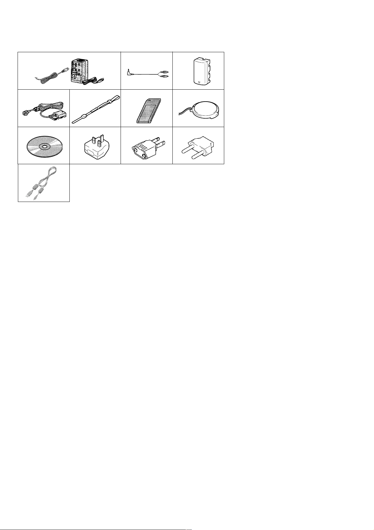
Supplied accessories
123
4567
890qa
qs
1 AC-VF10 AC power adaptor/charger,
Power cord (1)
2 A/V connecting cable (1)
3 NP-FS11 Battery pack (1)
4 DK-115 DC connecting cable (1)
5 Wrist strap (1)
6 Memory Stick (8MB) (1)
7 Lens cap/Lens cap strap (1)
8 CD-ROM (1)
9 Conversion plug 3P adaptor (1)
UK, Hong Kong model
0 2-pin conversion adaptor (1)
E model
qa 2-pin conversion adaptor (1)
Tour ist model
qs USB cable (1)
SAFETY-RELATED COMPONENT WARNING!!
COMPONENTS IDENTIFIED BY MARK 0 OR DOTTED
LINE WITH MARK 0 ON THE SCHEMATIC DIAGRAMS
AND IN THE PARTS LIST ARE CRITICAL TO SAFE
OPERATION. REPLACE THESE COMPONENTS WITH
SONY PARTS WHOSE PART NUMBERS APPEAR AS
SHOWN IN THIS MANUAL OR IN SUPPLEMENTS PUBLISHED BY SONY.
SAFETY CHECK-OUT
After correcting the original service problem, perform the following
safety checks before releasing the set to the customer.
1. Check the area of your repair for unsoldered or poorly-soldered connections. Check the entire board surface for solder
splashes and bridges.
2. Check the interboard wiring to ensure that no wires are
“pinched” or contact high-wattage resistors.
3. Look for unauthorized replacement parts, particularly transistors, that were installed during a previous repair. Point them
out to the customer and recommend their replacement.
ATTENTION AU COMPOSANT AYANT RAPPORT
À LA SÉCURITÉ!
LES COMPOSANTS IDENTIFIÉS P AR UNE MARQUE 0
SUR LES DIAGRAMMES SCHÉMATIQUES ET LA LISTE
DES PIÈCES SONT CRITIQUES POUR LA SÉCURITÉ
DE FONCTIONNEMENT. NE REMPLACER CES COMPOSANTS QUE PAR DES PIÈCES SONY DONT LES
NUMÉROS SONT DONNÉS DANS CE MANUEL OU
DANS LES SUPPLÉMENTS PUBLIÉS PAR SONY.
4. Look for parts which, though functioning, show obvious signs
of deterioration. Point them out to the customer and recommend their replacement.
5. Check the B+ voltage to see it is at the values specified.
6. Flexible Circuit Board Repairing
• Keep the temperature of the soldering iron around 270 ˚C
during repairing.
• Do not touch the soldering iron on the same conductor of
the circuit board (within 3 times).
• Be careful not to apply force on the conductor when sol-
dering or unsoldering.
– 2 –
Page 3

TABLE OF CONTENTS
Section Title Page Section Title Page
SERVICE NOTE................................................................... 5
1. GENERAL
Identifying the Parts................................................................. 1-1
Preparing the Power Supply.................................................... 1-2
Setting the Date and Time....................................................... 1-3
Inserting the “Memory Stick” ................................................... 1-4
Recording Still Images ............................................................ 1-4
Recording Moving Images....................................................... 1-5
Playing Back Still Images ........................................................ 1-5
Playing Back Moving Images .................................................. 1-6
Viewing Images Using a Personal Computer ......................... 1-6
Image File Storage Destinations and Image Files.................. 1-7
Before Performing Advanced Operations ............................... 1-7
Various Recording ................................................................... 1-9
Various Playback ..................................................................... 1-11
Editing ..................................................................................... 1-12
Precautions.............................................................................. 1-14
On “Memory Sticks” ................................................................. 1-14
Using Your Camera Abroad ..................................................... 1-14
Troubleshooting ....................................................................... 1-14
Warning and Notice Messages ............................................... 1-15
Self-diagnosis Display ............................................................. 1-16
LCD Screen Indicators ............................................................ 1-16
2. DISASSEMBLY
• Attachment of CPC-9 Jig ...................................................... 2-1
2-1. Rear Cabinet Block ....................................................... 2-2
2-2. Zoom Lens Block ........................................................... 2-2
2-3 Cabinet (LT) Block ......................................................... 2-3
2-4. Lens Block ..................................................................... 2-3
2-5. LCD Panel Block, Control Switch Block (FK) ............... 2-4
2-6. HI-73, DD-148 Boards, Battery Holder Block ............... 2-5
2-7. Upper Cabinet Block, Flash Unit (MC) ......................... 2-5
2-8. Front Cabinet Assembly ................................................ 2-6
2-9. Removal and Attachment of FP-37 Flexible Board ...... 2-7
2-10. To Fold the New FP-37 Flexible Board ......................... 2-7
2-11. Cr ystal Indication Module ............................................. 2-8
2-12. Flash Unit (ST) .............................................................. 2-8
2.13. Circuit Boards Location................................................. 2-9
2-14. Flexible Boards Location............................................... 2-9
3. BLOCK DIAGRAMS
3-1. Overall Block Diagram................................................... 3-1
3-8. Power Block Diagram 1 ................................................. 3-15
3-9. Power Block Diagram 2 ................................................. 3-17
3-10. Power Block Diagram 3................................................. 3-19
4. PRINTED WIRING BOARDS AND
SCHEMATIC DIAGRAMS
4-1. Frame Schematic Diagrams.......................................... 4-3
Frame Schematic Diagram (1/2)................................... 4-3
Frame Schematic Diagram (2/2)................................... 4-5
4-2. Printed Wiring Boards and Schematic Diagrams ......... 4-7
CD-283 Printed Wiring Board ....................................... 4-7
CD-283 Schematic Diagram ......................................... 4-9
HI-73 Printed Wiring Board ........................................... 4-27
HI-73 (LCD Drive) Schematic Diagram......................... 4-31
HI-73 (Timing Generator) Schematic Diagram ............. 4-33
HI-73 (Video) Schematic Diagram ................................ 4-35
HI-73 (Audio) Schematic Diagram ................................ 4-37
HI-73 (USB I/F) Schematic Diagram............................. 4-39
HI-73 (Hi Control) Schematic Diagram ......................... 4-41
DD-148 Printed Wiring Board ....................................... 4-43
DD-148 Schematic Diagram ......................................... 4-45
CN-121 Printed Wiring Board and
Schematic Diagram ....................................................... 4-47
FK Schematic Diagram ................................................. 4-49
CF/MANUAL FOCUS BLOCK, ST
Schematic Diagrams ..................................................... 4-51
PW, MC Schematic Diagrams....................................... 4-52
4-3. Waveforms ..................................................................... 4-53
4-4. Parts Location ............................................................... 4-56
5. ADJUSTMENTS
Before Starting Adjustment ..................................................... 5-1
1-1. Adjusting Items when Replacing
Main Parts and Boards.................................................. 5-2
5-1. Camera Section Adjustment ......................................... 5-3
1-1. Preparations Before Adjustment ................................... 5-3
1-1-1. List of Service Tools ................................................. 5-3
1-1-2. Preparations ............................................................. 5-4
1-1-3. Discharging of the Flashlight Power Supply ............ 5-4
1-1-4. Precautions .............................................................. 5-6
1. Setting the Switch .................................................... 5-6
2. Order of Adjustments ............................................... 5-6
3. Subjects.................................................................... 5-6
4. Preparing the Flash Adjustment Box ....................... 5-7
1-2. Initialization of B, D, E, F, 7 Page Data ......................... 5-8
1-2-1. Initialization of D Page Data .................................... 5-8
1. Initializing D Page Data............................................ 5-8
2. Modification of D Page Data .................................... 5-8
3. D Page Table ............................................................ 5-8
1-2-2. Initialization of B, E, F, 7 Page Data ........................ 5-9
1. Initializing B, E, F, 7 Page Data................................ 5-9
2. Modification of B, E, F, 7 Page Data ........................ 5-9
3. B Page Table ............................................................ 5-9
4. E Page Table ............................................................ 5-9
5. F Page Table............................................................. 5-10
6. 7 Page Table............................................................. 5-11
1-3. Video System Adjustments ........................................... 5-12
1. Video Sync Level Adjustment ....................................... 5-12
2. Video Burst Level Adjustment ....................................... 5-12
1-4. Camera System Adjustment ......................................... 5-13
1. HALL Adjustment .......................................................... 5-13
2. Flange Back Adjustment
(Using the minipattern box)........................................... 5-14
3. Flange Back Check ....................................................... 5-15
4. F No. Standard Data Input ............................................ 5-16
5. Mechanical Shutter Adjustment.................................... 5-16
6. Picture Frame Setting.................................................... 5-17
7. Light Level Adjustment and ND Shutter Check ............ 5-18
8. Mixed Color Cancel Adjustment .................................... 5-18
9. Auto White Balance Standard Data Input ..................... 5-19
10. Auto White Balance ND Filter Compensation ............... 5-19
11. Auto White Balance Adjustment ................................... 5-20
12. Color Reproduction Adjustment .................................... 5-21
12-1. Color Reproduction Adjustment
(Without ND Filter) ................................................... 5-21
12-2. Color Reproduction Adjustment (With ND Filter) .... 5-21
13. Color Reproduction Check............................................ 5-22
14. White Balance Check.................................................... 5-23
15. Strobe White Balance Adjustment ................................ 5-24
16. Strobe Light Level and White Balance Check .............. 5-24
17. CCD Black Defect Compensation................................. 5-25
18. CCD White Defect Compensation ................................ 5-25
1-5. LCD System Adjustments ............................................. 5-26
1. LCD Initial Data Input.................................................... 5-27
2. VCO Adjustment (HI-73 Board) .................................... 5-27
3. D Range Adjustment (HI-73 Board).............................. 5-28
4. Bright Adjustment (HI-73 Board)................................... 5-28
5. Contrast Adjustment (HI-73 Board) .............................. 5-29
6. Color Adjustment (HI-73 Board) ................................... 5-29
7. V-COM Level Adjustment (HI-73 Board)....................... 5-30
8. V-COM Adjustment (HI-73 Board) ................................ 5-30
9. White Balance Adjustment (HI-73 Board)..................... 5-31
1-6. System Control System Adjustments ........................... 5-32
1. Battery Down Adjustment ............................................. 5-32
2. ZOOM-VR Center Adjustment ...................................... 5-33
5-2. Service Mode ................................................................ 5-34
2-1. Adjusting Remote Commander ..................................... 5-34
– 3 –
Page 4

Section Title Page
1. Used Adjusting Remote Commander ........................... 5-34
2. Precautions upon Using
the Adjusting Remote Commander............................... 5-34
2-2. Data Process ................................................................. 5-35
2-3. Service Mode ................................................................ 5-36
1. Setting the Test Mode.................................................... 5-36
2. Bit Value Discrimination ................................................ 5-36
3. Balance Sensor Check.................................................. 5-36
4. Switch Check (1) ........................................................... 5-36
5. Switch Check (2) ........................................................... 5-37
6. REPAIR PARTS LIST
6-1. Exploded Views ............................................................. 6-1
6-1-1. Battery Holder Assembly ......................................... 6-1
6-1-2. Front Cabinet Assembly........................................... 6-2
6-1-3. Rear Cabinet Assembly ........................................... 6-3
6-1-4. Lens Cabinet Assembly ........................................... 6-4
6-1-5. Lens Assembly......................................................... 6-5
6-2. Electrical Parts List ....................................................... 6-6
* The color reproduction frame is shown on page 134.
The parts reference sheet is shown on page 135.
– 4 –
Page 5
SERVICE NOTE
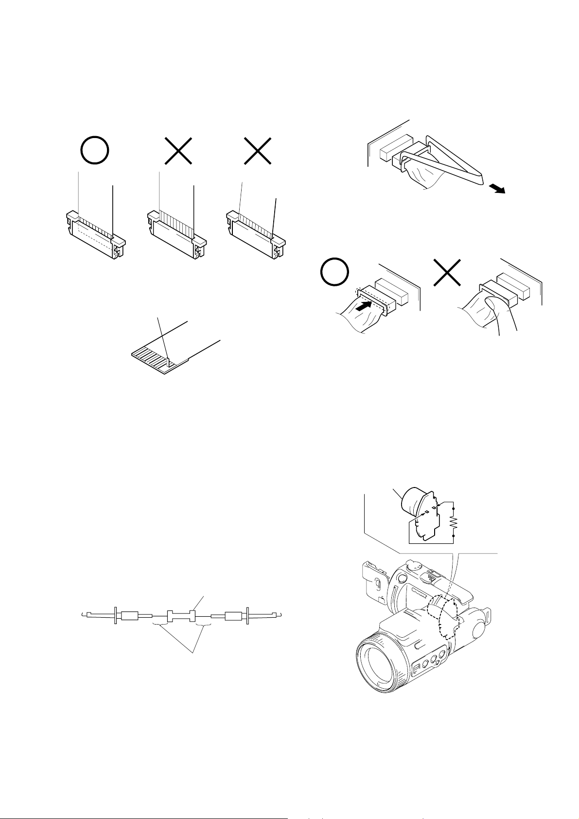
When installing a connector, don’t press down at wire of connector.
It is possible that a wire is snapped.
• NOTE FOR REPAIR
Make sure that the flat cable and flexible board are not cracked of
bent at the terminal.
Do not insert the cable insufficiently nor crookedly.
Cut and remove the part of gilt
which comes off at the point.
(Be careful or some
pieces of gilt may be left inside)
When remove a connector, don’t pull at wire of connector.
It is possible that a wire is snapped.
[Discharging of the FLASH unit’s charging capacitor]
The charging capacitor of the FLASH unit is charged up to the
maximum 300 V potential.
There is a danger of electric shock by this high voltage when the
battery is handled by hand. The electric shock is caused by the
charged voltage which is kept without discharging when the main
power of the unit is simply turned off. Therefore, the remaining
voltage must be discharged as described below.
Preparing the Short Jig
T o preparing the short jig, a small clip is attached to each end of a
resistor of 1 kΩ /1 W (1-215-869-11).
Wrap insulating tape fully around the leads of the resistor to prevent electrical shock.
1 kΩ/1 W
Wrap insulating tape.
Discharging the Capacitor
Short-circuit between the positive and the negative terminals of
charged capacitor with the short jig about 10 seconds.
Flash unit (MC)
Capacitor
R: 1 kΩ/1 W
(Part code:
1-215-869-11)
– 5 –
Page 6
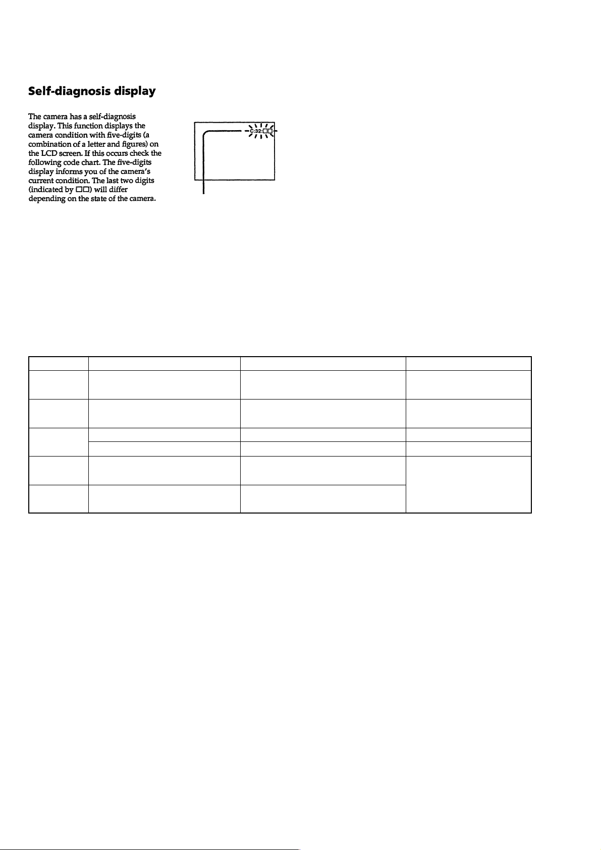
[Description on Self-diagnosis Display]
Self-diagnosis display
• C: ss: ss
You can reverse the camera malfunction yourself. (However , contact your Sony dealer or local
authorized Sony service facility
when you cannot recover from
the camera malfunction.)
• E: ss: ss
Contact your Sony dealer or local authorized Sony service facility.
Display Code
C:04:ss
C:32:ss
C:13:ss
E:61:ss
E:91:ss
Use a NP-FS11/F10 battery pack.
Turn the power off and on again.
Format the “Memory stick”.
Insert a new “Memory Stick”.
Checking of lens drive circuit.
*1
Checking of flash unit or replacement
of flash unit.
Countermeasure
You are using a battery pack that is not an
“InfoLITHIUM” battery pack.
Trouble with hardware.
Unformatted memory stick is inserted.
Memory stick is broken.
When failed in the focus and zoom
initialization.
Abnormality when flash is being
charged.
Note : The error code is cleared if the battery is removed, except defective
flash, unit.
*1: The error display is given in two ways.
*2: When the flash charging failed, Page: D, Address: 67, Data: 04 are
written.
After repair, be sure to write Page: D, Address: 67, Data: 00.
Cause
Caution Display During Error
for “InfoLITHIUM” BATTERY ONLY
SYSTEM ERROR
FORMAT ERROR
MEMORY STICK ERROR
—
*2
– 6 –
Page 7
SECTION 1
GENERAL
DSC-F505V
This section is extracted from
instruction manual.
WARNING
To prevent fire or shock hazard, do
not expose the unit to rain or
moisture.
For the Customers in the
U.S.A.
This symbol is intended to
alert the user to the presence
of uninsulated “dangerous
voltage” within the
product’s enclosure that
may be of sufficient
magnitude to constitute a
risk of electric s h ock to
persons.
This symbol is intended to
alert the user to the presence
of important operating and
maintenance (servicing)
instructions in the literature
accompanying the
Never expose the battery pack to
temperature above 140°F (60°C), such as in
a car parked in the sun or under direct
sunlight.
If you have any questions about this product,
you may call:
or write to:
appliance.
Sony Customer Information Center
1-800-222-SONY (7669)
Sony Customer Information Center
1 Sony Drive, Mail Drop #T1-11, Park
Ridge, NJ 07656
2
CAUTION
You are cautioned that any changes or
modifications not expressly approved in this
manual could void your authority to operate
this equipment.
Declaration of Conformity
Trade Name: SONY
Model No.: DSC-F505V
Responsible Party:Sony Electronics Inc.
Address: 1 Sony Drive, Park
Telephone No.: 201-930-6972
This device complies with Part 15 of the
FCC Rules. Operation is subject to the
following two conditions: (1) This
device may not cause harmful
interference, and (2) this device must
accept any interference received,
including interference that may cause
undesired operation.
Note:
This equipment has been tested and found to
comply with the limits for a Class B digital
device, pursuant to Part 15 of the FCC
Rules. These limits are designed to provide
reasonable protection against harmful
interference in a residential installation. This
equipment generates, uses, and can radiate
radio frequency energy and, if not installed
and used in accordance with the
instructions, may cause harmful interference
to radio communications. However, there is
no guarantee that interference wi ll not occur
in a particular installation. If this equipment
does cause harmful interference to radio or
television reception, which can be
determined by turning the equipment off and
on, the user is encouraged to try to correct
the interference by one or more of the
following measures:
— Reorient or relocate the receiving
antenna.
— Increase the separation between the
equipment and receiver.
— Connect the equipment into an outlet
on a circuit dif fe rent from that t o whi ch
the receiver is connected.
— Consult the dealer or an experienced
radio/TV technician for help.
Ridge, NJ 07656
USA
The shielded interface cable recommended
in this manual must be used with this
equipment in order to comply with the limits
for a digital device pursuant to Subpart B of
Part 15 of FCC Rules.
For the Customers in the
U.S.A. and Canada
DISPOSAL OF LITHIUM ION
BATTERY .
LITHIUM ION BATTERY.
DISPOSE OF PROPERLY.
You can return your unwanted lithium ion
batteries to your nearest Sony Service
Center or Fac tory Service Center.
Note:
In some areas the disposal o f li thium ion
batteries in household or business trash may
be prohibited.
For the Sony Service Center near est yo u call
1-800-222-SONY (United States only)
For the Sony Factory Servic e Cent er neare st
you call 416-499-SONY (Canada only)
Caution:
Do not handle damaged or leaking lithium
ion battery.
For the Customers in Canada
CAUTION
TO PREVENT ELECTRIC SHOCK, DO
NOT USE THIS POLARIZED AC PLUG
WITH AN EXTENSION CORD,
RECEPTACLE OR OTHER OUTLET
UNLESS THE BLADES CAN BE FULLY
INSERTED TO PREVENT BLADE
EXPOSURE.
NOTICE FOR THE
CUSTOMERS IN THE UNITED
KINGDOM
A moulded plug complying with BS 1363 is
fitted to this equipment for your safety and
convenience.
Should the fuse in the plug supplied need to
be replaced, a 5 AMP fuse approved by
ASTA or BSI to BS 1362, (i.e. marked with
or mark) must be used.
If the plug supp lied with this eq uipment has
a detachable fuse cover, be sure to attach the
fuse cover after you change the fuse. Never
use the plug without the fuse cover. If you
should lose the fuse cover, please contact
your nearest Sony service station.
For the Customers in
Germany
Directive:EMC Directive 89/336/EEC.92/
31/EEC
This equipment complies with the EMC
regulations when used under the following
circumstances:
•
Residential area
•
Business district
•
Light-industry district
(This equipment complies with the EMC
standard regulations EN55022 Class B.)
Attention
The electromagnetic fields at the specific
frequencies may influence the pictu re a nd
sound of this camera.
“Memory Stick”
N50
For the Customers in CANADA
This Class B digital apparatus complies with
Canadian ICES-003.
3
For the Customers in the
U.S.A.
This device complies with Part 15 of the
FCC Rules. Operation is subject to the
following two conditions: (1) This device
may not cause harmful interference, and
(2) this device must accept any interference
received, including interference that may
cause undesired operation.
Be sure to read the following
before using your camera
Trial recording
Before you record one-time events, you may
want to make a trial recording to make sure
that the camera is working correctly.
No compensation for contents of
the recording
Contents of the recording cannot be
compensated for if recording or playback is
not possible due to a malfunction of your
camera, etc.
Notes on image data compatibility
•
This camera conforms with the Design
Rules for Camera File Systems universal
standard established by the JEIDA (J a pan
Electronic Industries Devel o pm ent
Association). You cannot play back on
your camera still images recorded on other
equipment (DCR-TRV890E/TRV900/
TRV900E, DSC-D700, DSC-D770) that
does not conform with this universal
standard. (These models are not sold in
some areas.)
•
Playback of images recorded with your
camera on other equipment and playback
of images recorded or edited with other
equipment on your camera are not
guaranteed.
Precaution on copyright
Television programs, films, video tapes, and
other materials may be copyrighted.
Unauthorized recording of such materials
may be contrary to the provision of the
copyright laws.
Do not shake or strike the camera
In addition to malfunctions and inability to
record images, this ma y render the
“Memory Stick” unusable or image data
breakdown, damage or loss may occur.
LCD screen and lens
•
The LCD screen is manufactured using
high-precision technology. However, there
may be some tiny black points and/or
bright points (red, blue or green in color)
that constantly appear on the LCD screen.
These points are normal in the
manufacturing process and do not affect
the recording in any way. Over 99.99% of
the pixels are operational for effective use.
•
Be careful when placing the camera near a
window or outdoors. Exposing the LCD
screen or the lens to direct sunlig ht for
long periods may cause malfunctions.
Do not get the camera wet
When taking pictures outdoors in the rain or
under similar conditions, be careful not to
get the camera wet. If moisture
condensation occurs, refer to page 55 and
follow the instructions on how to remove it
before using the camera.
Back up recommendation
To avoid the potential risk of data loss,
always copy (back up) data to a disk.
About the Carl Zeiss lens
This camera is equipp ed with a Carl Z eiss
lens which is capable of reproducing fine
images. The lens for this camera uses the
MTF* measurement system for cameras
developed jointly by Carl Zeiss, in
Germany, and Sony Corporation, and
offers the same quality as other Carl
Zeiss lenses.
MTF is the abbreviation of Modulation
∗
Transfer Function/Factor, a numeric
value indicating the ability to reproduce
the subject contrast.
Getting started
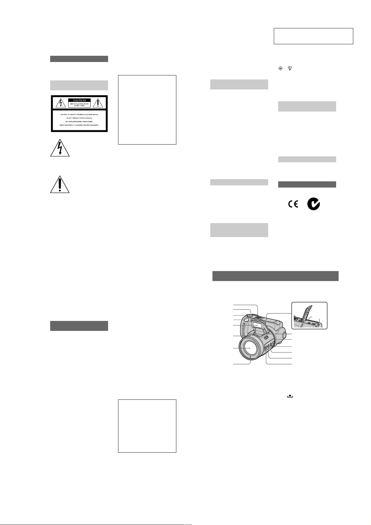
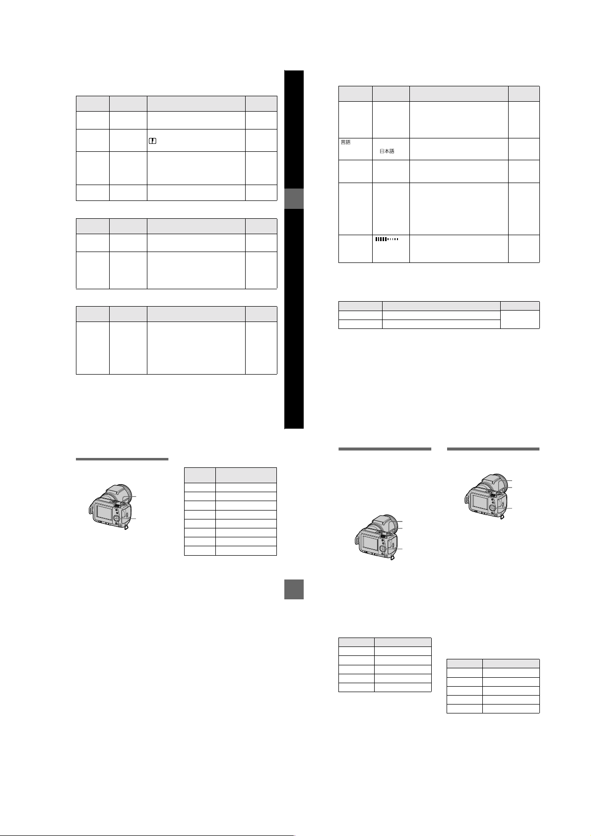
Identifying the parts
See the pages in parent hes es for details of operation.
1
2
3
4
5
6
77
8
A Built-in microphone
Do not touch while recording.
B Self-timer/Recording lamp
C MODE selector (30)
D Shutter button (16) (21)
E Flash (19)
F Focus ring (40)
G Lens
H Photocell window for flash
Do not block while recording.
I A/V OUT jack (49)
Audio output is monaural.
J DIGITAL I/O (USB) jac k (26) (27)
K OPEN (flash) switch (19)
L SPOT METER button (42)
M (one-push white balance)
N WHT BAL (white balance)
O MACRO button (40)
P FOCUS AUTO/MANUAL switch
09
qa
qs
qd
qf
qg
qh
button (43)
button (43)
(40)
4
6
1-1
Page 8
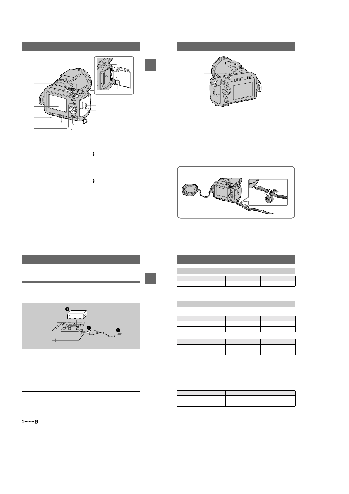
7
Getting started
1
3
1
2
3
4
5
6
A Zoom lever
B POWER switch
POWER lamp
C LCD screen
D LCD BACK LIGHT switch
Usually set to ON. Set to OFF to
save the battery if you use your
camera in bright place.
E PROGRAM AE ADJ button
VOLUME +/– button
F PROGRAM AE button (41)
G Battery eject lever (11)
9
8
0
qa
qs
qd
qf
qg
H Access lamp (15)
I Battery/“Memory Stick” cover
J (flash) button
Flash lamp
K OPEN switch
L Slot cover for AC power
adaptor/charger (12)
M (External flash) jack
N DISPLAY button
O Control button
2
A Speaker
B Hook for the wrist/shoulder
strap
C Tripod receptacle (bottom
surface)
Use a tripod with a screw length of
less than 9/32 inch (6.5 mm). You
will be unable to firmly secure the
camera to tripods having longer
screws, and may damage the
camera.
Attaching the lens cap (supplied) and the wrist strap (supplied).
Lens cap
Lens cap strap
7
8
D Hook for the lens cap/shoulder
strap
Be sure to remove the lens cap
before turning on your camera.
Wrist strap
4
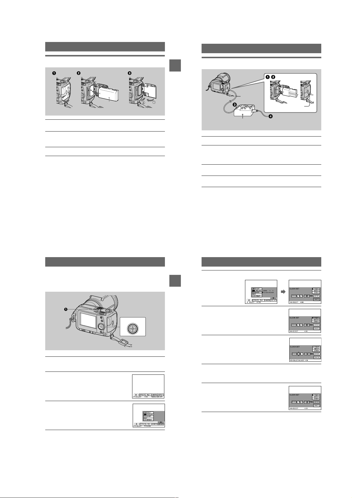
Preparing the power supply
Charging the battery pack
Your camera operates only with the “InfoLITHIUM” NP-FS11 battery pac k* (S
series). You cannot use any other battery pack.
Battery pack (S series)
CHARGE lamp
(orange)
AC-VF10 AC power adaptor/charger (supplied)
Connect the AC power adaptor/charger and the wall outlet (mains).
1
Insert the battery pack in the direction of the v mark. Slide the
2
battery pack in the direction of the arrow.
The CHARGE lamp lights up when charging begins. When the CHARGE lamp
normal charge
goes off,
use the battery longer than usual, leave the battery pack inserted for about one
hour after normal charge is completed.
is completed. For
To remove the battery pack
Slide the battery pack in the direction opposite the v mark.
*
What is “InfoLITHIUM”?
“InfoLITHIUM” is a lithium ion battery pack which can exchange information such as battery
consumption with compatible vide o equipment. This unit is compatible with the
“InfoLITHIUM” battery pack (S series). “InfoLITHIUM” S series battery pac ks have the
mark. “InfoLITHIUM” is a trademark of Sony Corporation.
full charge
To the wall outlet
(mains)
, which allows you to
Getting started
Charging time
Battery pack Full charge (min.) Normal charge (min.)
NP-FS11 (supplied) 170 110
Approximate time to charge a completely discharged battery pack using the ACVF10 AC power adaptor/charger.
Battery life and number of images that can be recorded/played back
STILL mode recording*
LCD BACK LIGHT Battery life (min.) Number of im ages
ON 70 (65) 1300 (1200)
OFF 85 (75) 1600 (1400)
STILL mode playback**
LCD BACK LIGHT Battery life (min.) Number of im ages
ON 110 (100) 2200 (2000)
OFF 145 (130) 2900 (2600)
Approximate battery life and number of images that can be r ecorded/played back
with a fully charged battery pack at a temperature of 77°F (25°C), 640×480 image
size and in NORMAL recording mode. Numbers in parentheses indicate the time
when you use a normally charged battery pack.
Recording at about 4-second intervals
∗
Playing back single images in order at about 3-sec ond intervals
∗∗
MOVIE mode recordi ng
LCD BACK LIGHT Continuous recording time (min.)
ON 75 (65)
OFF 85 (75)
Approximate time that can be recorded with a fully charged battery pack at a
temperature of 77°F (2 5 °C) and 160×112 image size. Numbers in parentheses
indicate the time when yo u use a normally charged battery pack.
Notes
•
The battery life and number of images will be decrease d if you use your camera at low
temperatures, use the flash, repeatedly turn the power on/off or use the zoom.
•
The capacity of the “Memory Stick” is limited. The above figures are a guide when you
continuously record/play back while replacing the “Memory Stick.”
•
If sufficient battery remaining time is in dic ated but the power runs out soon, fully charge the
battery so that the correct battery remaining time appears.
•
Do not expose the battery pack to water.
9
10
1-2
Page 9
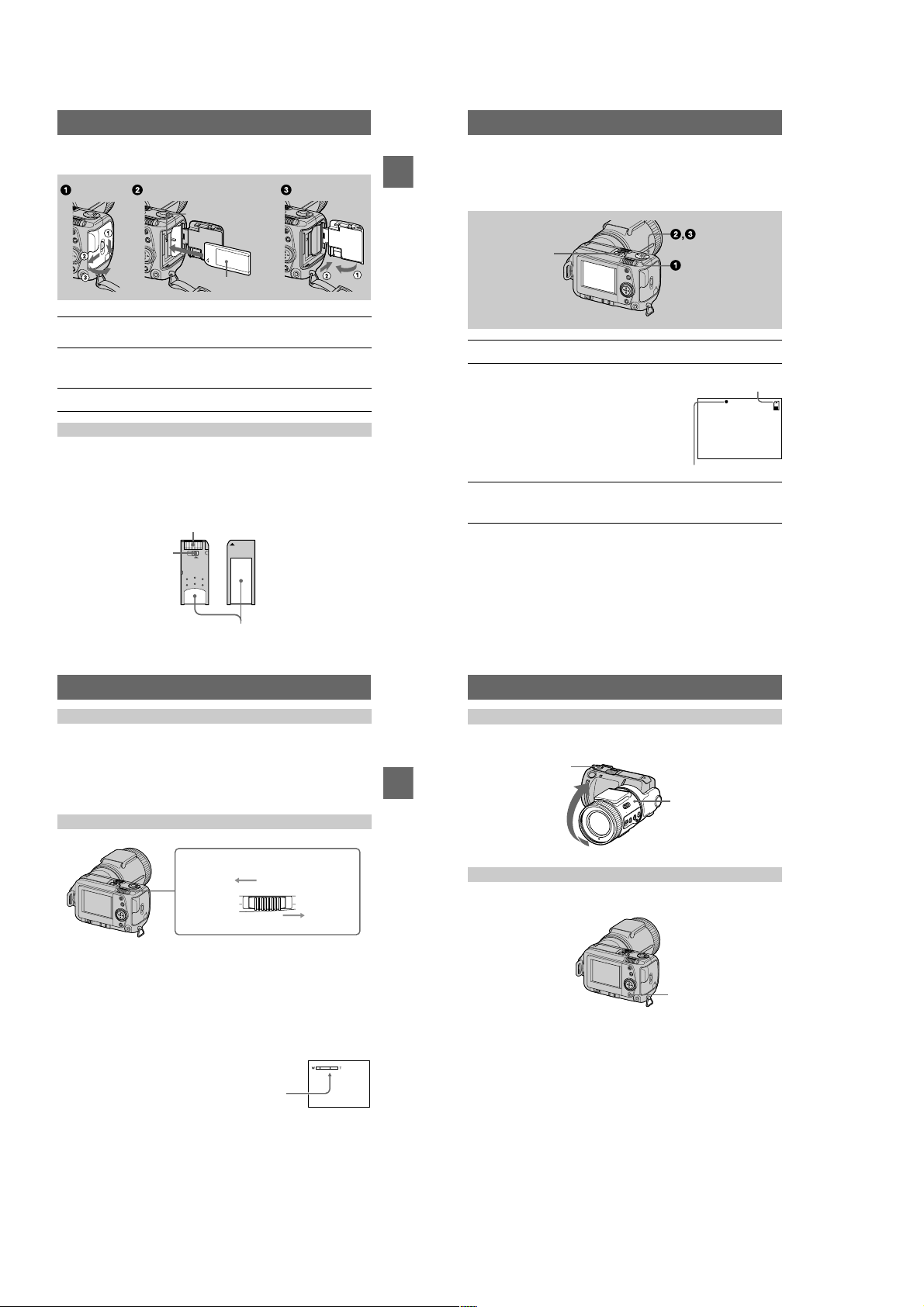
Installing the battery pack
Battery eject lever
Battery pack
(S series)
Open the battery/“Memory Stick” cover.
1
Open the cover while sliding the OPEN switch in the direction of the arrow.
Install the battery pack.
2
Insert the battery pa ck with the v mark facing toward the battery compartment
as illustrated.
Close the battery/“Memory Stick” cover.
3
To remove the battery pack
Open the battery/“Memory Stick” cover. Slide the battery eject lever upward,
and remove the battery pack.
Be careful not to drop the battery pack when removing it.
Battery remaining indicator
The LCD screen on the camera shows the remaining time for which you can still
record or play back images.
This indication may not be ent i re ly accurate depending on the condi t io ns of use and
the operating environment.
Auto power-off function
If you do not operate the camera for abou t three mi nutes dur ing recor ding, the camera
turns off automaticall y to prevent wearing down the battery. To use the camera again,
slide the POWER switch to turn o n th e camera again.
Getting started
Using the AC power adaptor
DK-115
DC connecting
cable (supplied)
Slot cover for AC power
adaptor/charger
AC-VF10 AC power adaptor/
charger (supplied)
Open the battery/“Memory Stick” cover.
1
Insert the one end of the DK-115 DC conn ect i ng cable to the
2
battery terminal, and close the cover.
When inserting the cable, open the slot cover for AC power adaptor/charger and
be careful not to pinch the cable .
Connect the other end of the DC connecting cable to the AC power
3
adaptor/charger.
Connect the power cord (mains lead) to the AC power adaptor/
4
charger and then to a wall outlet (mains).
Using a car battery
Use Sony DC adaptor/charger (not supplied).
Power cord (mains lead)
Setting the date and time
When you first use your camera, set the date and time. If these are not set, the
CLOCK SET screen appears whenever you turn on your camera for recording.
Control button
Slide the POWER switch in the direction of the arrow to turn on the
1
power.
The POWER lamp lights up.
Press v on the control button.
2
The menu bar appears on the L C D screen.
Select [SETUP] with B on the control button,
3
then press the cen t er z.
11
Getting started
12
Select [CLOCK SET] with v/V on the control button, then press the
4
center z.
Select the desired date display format with
5
on the control button, then press the
v/V
center z.
Select from [Y/M/D] (year/month/day), [M/D/Y]
(month/day/year) or [ D /M / Y ] (day/month/year).
Select the year, month, day, hour or minute
6
item you want to set with b/B on the control
button.
The item to be set is indicated with v/V.
Set the numeric value with v/V on the control button, then press
7
the center z to enter it.
After entering the number, v/V moves to the next item.
If you selected [D/M/Y] in step 5, set the time on a 24-hour cycle.
Select [ENTER] with B on the control button,
8
then press the center z at the desired
moment to begin clock movement.
The date and time are entered.
To cancel the date and time setting
Select [CANCEL] with v/V/b/B on the control button, then press the center z.
13
14
1-3
Page 10
Inserting the “Memory Stick”
Access lamp
“Memory Stick”
Open the battery/“Memory Stick” cover.
1
Open the cover while sliding the OPEN switch in the direction of the arrow.
Insert the “Memory Stick.”
2
Insert the “Memory Stick” with the B mark facing toward the battery
compartment as illustrated until it clicks.
Close the battery/“Memory Stick” cover.
3
Removing the “Memory Stick”
Open the battery/“Memory Stick” cov er, then press the “Memory Stick” once lightly.
Notes
•
Insert the “Memory Stick” firmly until it clicks, otherwise a message such as “MEMORY
STICK ERROR” will be displayed.
•
Never remove the “Memory Stick” or turn off the power while the access lamp is lit up.
•
You cannot record or edit images on a “Memory Stick” if the erasure prevention switch is set to
the LOCK position.
Connector
Erasure prevention switch
OC
Label space
15
Getting started
Basic operations
Recording
B
Recording still images
Still images are recorded in JPEG format.
To record still images, slide the POWER switch to the right to turn on the power and
insert a “Memory Stick.”
POWER switch
Set the MODE selector to STILL.
1
Press and hold the shutter button halfway
2
down and check the image.
While the AE lock indicator z (green) is flashing,
the image freezes momentarily, but is not yet
recorded. When the camera finishes the automatic
adjustments*, the AE lock indicator z lights up
and the camera is ready for recording.
To cancel the recording, release the shutter button.
Press the shutter button fully down.
3
The shutter sounds and th e i m age is recorded on the “Memory Stick.”
When “RECORDING” disappears, you can record the next image.
Exposure and focus are automatically adjusted.
∗
The number of images you can record on a “Memory Stick”
See pages 37 to 39.
Notes
•
While the image is being recorded on the “Memory Stick,” do not shake or strike the camera.
Also, do not turn the power off, or remove the battery pack or “Memory Stick.”
•
When recording a bright subject , the LC D screen co lor may chang e af ter AE lo ck, b ut thi s does
not affect the recorded imag e.
16
Remaining memory
capacity indicator
AE lock indicator
Checking the last recorded image (Quick Review)
You can check the last recorded image by clearing the menu bar from the screen
(page 32) and pressing b on the control button. To return to the normal re cor di ng
mode, press lightly on the shutter button or select [RETURN] with b/B on the
control button and then press th e center z. You can also delete the image first by
selecting [DELETE] on the Quick Review screen with b/B on the control b u tto n a nd
pressing the center z, and then selecting [OK] with v/V on the control button and
pressing the center z.
Using the zoom feature
Zoom lever
W side: for wide-angle (subject appears
farther away)
T side: for telephoto (subject appears closer)
Minimum focal distance to the subject
W side: About 9 7/8 inches (25 cm) or more
T side: About 31 1/2 inches (80 cm) or more
To record even closer subjects, see page 40.
Digital zoom function
This camera has a digital zoom function.
Digital zoom enlarges the image by digital processing and it starts to function when
zoom exceeds 5×.
The T side of the bar shows the
digital zooming zone.
Using digital zoom
•
The maximum zoom magnification is 10×.
•
Digital zooming dete ri or at es the picture quality. When digital zoom is not
necessary, set [DIGITA L ZOOM] to [OFF] in the menu settings (page 35).
Note
Digital zoom does not work for moving images.
BB
B
B
Recording
Changing the lens orientation
You can adjust the angle b y turning the lens part upward up to 90 degrees and
downward up to 50 degrees.
MODE selector
90°
50°
Lens part
LCD screen indicators during recording
Press DISPLAY to turn on/off the indicators on the LCD screen.
See page 65 for a detailed description of the indicated items.
DISPLAY
Notes
•
You cannot turn off the self-timer indicators and some of the indicators used in advanced
operations.
•
The indicators on the LCD screen are not recorded.
17
18
1-4
Page 11
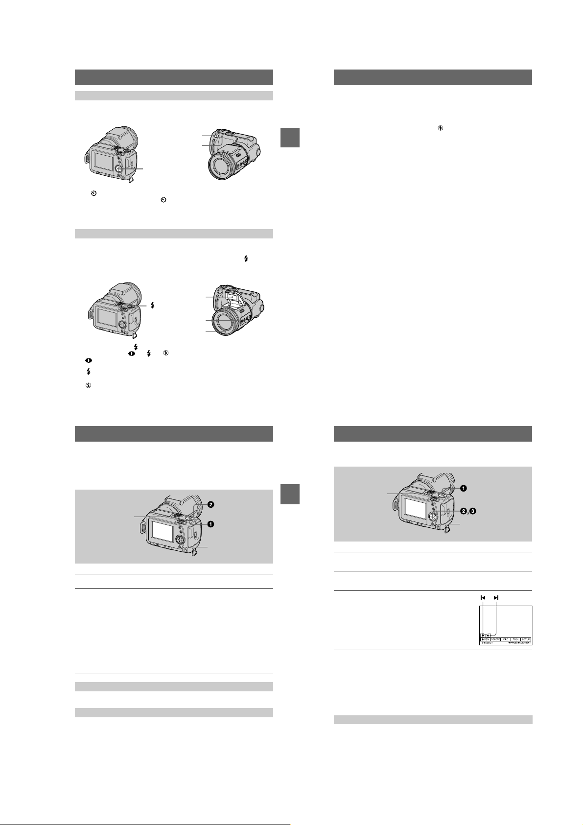
Using the self-timer
When you use the self-timer function, the subject is recorded about 10 seconds after
you press the shutte r butt on.
Shutter button
Self-timer lamp
Control button
Select (self-timer) indicator on the LCD screen with v/V/b/B on the control
button, then press the center z. The (self-timer) ind i cat or appears on the LCD
screen, and about 10 seconds after you press the shutter button , th e subject is
recorded. The self-timer lamp flashes after you press the shutter button until the
shutter is released.
Recording images with the flash
Slide OPEN switch to make the flash avai lable . The fla sh po p s up. The initial setting
is auto (no indicator). In this mode, the flash automatically strobes when the
surroundings become dark. When you change the flash mode, press the (flash)
repeatedly so that the flash mode indicator appears on th e L CD sc reen. You can only
change the flash mode wh ile the flash is popped up.
Flash emitter
(
flash)
OPEN switch
Photocell window for
Each time you press the (flash), the indicator changes as follows.
(No indicator) t t t t (No indicator)
Auto red-eye reduction: The flash strobes before recording to reduce the
Forced flash: The flash strobes regardles s of the surrounding
No flash: The flash does not strobe.
You can change the brightness of the flash (FLASH LEVEL) i n t he menu settings
(page 35).
red-eye phenomenon.
brightness.
flash
19
BB
B
B
Recording
Notes
•
The recommended shooting distance using the built-in flash is 31/32 feet to 8 1/3 feet (0.3 m to
2.5 m).
•
Attaching a conversion lens (not supplied) may block the light from the flash or cause the len s
shadow to appear.
•
You cannot use an external flash and the built-in flash at the same time.
•
If the flash is closed when it should be used, the (no-flash) indicator appears in the LCD
screen.
•
Auto red-eye reduction may not produce the desired red-eye reduction e ffects dependi ng on
individual differences, the distance to th e subject, if the subject does not see th e pr e-strobe, or
other conditions. In addition, red-eye reduction e ffects are also difficult to obtain if you se t the
shutter to a slow speed in the PROGRAM AE shutter pr ior ity mode.
•
The flash effect is not obtained easily when you use forced flash in a bright loc ation.
20
Recording moving images
Moving images with audio are recorded in MPEG format.
To record moving images, slide the POWER switch to the right to turn on the power
and insert a “Memory Stick.”
POWER switch
DISPLAY
Set the MODE selector to MOVIE.
1
Press the shutter button fully down.
2
“REC” appears on the LCD screen, and the image and sound are recorded on
the “Memory Stick.”
If you press the shutter button momentarily
The image and sound are recorded for five seconds. Yo u can change the
recording time to 10 or 15 seconds with [REC TIME SET] in the menu se ttings
(page 37).
If you hold the shutter button down
The image and sound are recor ded while the shutter button is held down for up
to 60 seconds. However, when [IMAGE SIZE] in the menu setting is set to
[320 (HQ)]/[320×240], the maximum recording time is 15 seconds (page 37).
Zooming or using the self-timer, etc.
See pages 17 to 19.
LCD screen indicators during recording
Press DISPLAY to turn on/off the indicators on the LCD screen.
These indicators are not recorded. See page 65 for a detailed description of the
indicators.
BB
B
B
Recording
Playback
B
Playing back still images
POWER switch
DISPLAY
Set the MODE selector to PLAY.
1
The last recorded image (still or moving) appears on the LC D screen.
Press v on the control button to display the menu bar on the LCD
2
screen.
Select the desired still image with the
3
control button.
Press v/V/b/B on the control button to select "b/B"
on the LCD screen, then press b/B on the control
button.
: To display the preceding image.
"b
: To display the next image.
B"
When the m enu bar is no t displayed
You can directly select and play back the image with b/B on the control button.
Notes
•
You might not be able to correctly pl ay b a ck images recorded w ith this camera on other
equipment.
•
You cannot play back on this camera images larger than the maximum image size that can be
recorded with this camera.
LCD screen indicators during still image playback
Press DISPLAY to turn on/off the indicators on the LCD screen.
See page 66 for a detailed description of the indicators.
21
22
1-5
Page 12
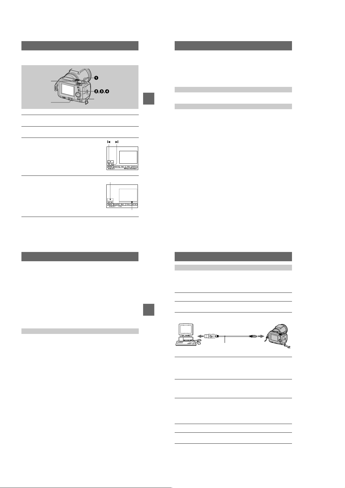
Playing back moving images
B
(playback)/
X
)
POWER switch
VOLUME +/–
Set the MODE selector to PLA Y.
1
The last recorded image (still or moving) appears on the LCD screen.
Press v on the control button to display the menu bar on the LCD
2
screen.
Select the desired moving image with the
3
control button.
Moving images are display ed one-size smaller than
still images.
Press v/V/b/B on the control button to sel ect "b/B"
on the LCD screen, then pr ess b/B on the control
button.
: To display the preceding image.
"b
: To display the next image.
B"
Select
(playback) on the LCD screen with
4
B
on the control button, then press the
v/V/b/B
center z.
The moving image and sound are played back.
During playback, B (playback) changes to X
(pause).
DISPLAY
(pause
Playback bar
When the menu bar is not displayed
You can directly select the image w it h b/B on the control button, and play back the
image and sound by pressing the center z. When you press the center z during
playback, playback is pa us ed.
Moving images recorded with the image of [320 (HQ)]
The images are displayed over the entire screen in steps 3 and 4.
Adjusting the volume
Press VOLUME +/– to adjust the volume.
BB
B
B
Playback
LCD screen indicators during moving image playback
Press DISPLAY to turn on/off the indicators on the LCD screen.
See page 66 for a detailed description of the indicators.
To pause playback
Select X (pause) on the LCD screen with v/V/b/B on the control button, then press
the center z.
23
Viewing images using a personal
computer
You can view data recorded with your camera on a personal computer and attach it to
e-mail. This section describes the method for installing the USB driver and viewing
images on a personal com puter. Be sure to also see the operation manua ls for your
personal computer and application software.
Note
Data recorded with your camera is stored in the following formats. Make sure that applications
that support these file formats are installed on your personal computer.
•
Still images (other than TEXT and uncompressed modes): JPEG format
•
Moving images/audio: MPEG format
•
Uncompressed mode still images: TIFF format
•
TEXT mode: GIF format
Recommended computer en vironment
Recommended Windows environment
OS: Microsoft Windows98, Windows 98SE
Standard installation is required.
Operation is not assured in an environment upgraded from:
Windows 3.1, Windows 95 to Windows98 or
Windows 98 to Windows 98SE.
CPU: MMX Pentium 200 MHz or faster
The USB connector must be provided as standard.
ActiveMovie Player (DirectShow) must be installed (to play back moving pictures).
Recommended Macintosh environment
Macintosh computer with the Mac OS 8.5.1/8.6/9.0 standard installation
However, note that the update to Mac OS 9.0 should be used for the following models.
•
iMac with the Mac OS 8.6 standard installation and a slot loading type CD-ROM drive
•
iBook or G4 with the Mac OS 8.6 standard installation
The USB connector must be provided as standard.
QuickTime 3.2 or newer must be installed (to play back moving pictures).
Notes
•
Operations are not guaranteed for either the Windows or Macintosh environment if you connect
two or more USB equipment to a single personal computer at the same time (except for the
USB keyboard and mouse which are provided as standard), or when using a hub.
•
Depending on the type of USB equipment that is used simultaneously, some equipment may
not operate.
•
Operations are not guaranteed for all the recommended computer environments menti o n ed
above.
24
Installing the USB driver
Before connecting your camera to your personal computer, install the USB driver to
the computer. The USB driver is contained together with application software for
viewing images on a CD-ROM which is supplied with your camera.
For Windows 98 users
Turn on your personal computer and allow Windows98 to load.
1
Insert the supplied CD-ROM in the CD-ROM drive of your personal
2
computer.
BB
B
B
Playback
Connect the USB jack on your camera with the USB connector on
3
your personal computer using the supplied USB cable.
to the USB connector
Personal computer
Insert a “Memory Stick” into your camera, connect the AC power
4
adaptor/charger and turn on your camera.
“PC MODE” appears on the LCD screen of your camera and the camer a i s set
to communication standby mode. Your personal computer recognizes the
camera, and the Windows 98 A d d Hardware Wizard starts.
Follow the on-screen messages to specify the CD-ROM drive and
5
install the USB driver.
The Add Hardware Wizard starts tw ic e because two different USB drivers are
installed. Be sure to allow the installation to complete without interrupting it.
Note
Be sure to insert a “Memory Stick” into your camera before installing the USB driver.
Otherwise, you will be unable to install the USB driver.
For Macintosh users
Turn on your personal computer and allow the Mac OS to load.
1
Insert the supplied CD-ROM in the CD-ROM drive of your personal
2
computer.
USB cable
to the USB ja ck
Push in until the
connector clicks
into place
25
26
1-6
Page 13
Double-click the CD-ROM drive icon to open the window.
3
Double-click the icon of the hard disk containing the OS to open
4
the window.
Move the following two files from the window opened in step 3 to
5
the “System Folder” icon in the window opened in step 4 (drag
and drop) .
•
Sony USB Driver
•
Sony USB Shim
When “Put these items into the Exte nsions folder?” appears, click
6
“OK.”
Restart your personal computer.
7
Viewing images
For Windows 98 users
Turn on the power of your personal computer and allow
1
Windows 98 to load.
Connect one end of the USB cable to the USB jack on the camera
2
and the other end to the USB connector on your personal
computer.
to the USB connector
Personal computer
Insert a “Memory Stick” into your camera, and connect the AC
3
power adaptor/charger to your camera and then to a wa ll out le t
(mains).
T ur n on the power of your camera.
4
“PC MODE” appears on th e LCD screen of the camera.
Open “My Computer” on Windows 98 and double click the newly
5
recognized drive. (Example: “Removable Disk (D:)”)
The folders inside the “Memory Stick” are displayed.
USB cable
to the USB ja ck
Push in until the
connector clicks
into place
Select and double-click the desired image/sound file from the
6
folder.
For the detailed folder and file name, see “Image file storage dest inations and
image files” (page 29).
Desired file type Double-click in this order
Still image “Dcim” folder t “100msdcf” folder t Image file
Moving image* “Mssony” folder t “Moml0001” folder t Image file*
Audio* “Mssony” folder t “Momlv100” fol d er t Audio file*
E-mail image
TIFF image
BB
B
B
Playback
(uncompressed)
Copying a file to the hard disk of your personal computer before viewing it is
∗
recommended. If you play back the file directly from the “M e mor y S tic k”, the image
and sound may break off.
“Mssony” folder t “Imcif100” folder t Image file
Notes on using your personal computer
“Memory Stick”
•
“Memory Stick” operations on your camera cannot be assur e d if the “Memory Stick” has been
formatted on your personal computer.
•
Do not optimize the “Mem or y St ic k” on a Windows machine. This will shorten the “Memory
Stick” life.
•
Do not compress the data on the “Memory Stick.” Co mpr e ssed files cannot be played back on
your camera.
Software
•
Depending on your application software, the file size may increase when you open a still image
file.
•
When you load an image modified using the supplied retouch software from your personal
computer to the camera or when you directly modify the image on the camera, the image
format will differ so the “FILE ERROR” message may appear and you may be unable to ope n
the file.
Communications with yo ur personal computer
Communications between your camera and your personal computer may not recover after
recovering from Suspend, Resume, or Sleep.
•
Windows and ActiveMovie, DirectShow are either registered trademarks or trademarks of
Microsoft Corporation in the United Sta te s and/or other countries.
•
Macintosh and Mac OS, QuickTime are trademarks of Apple Computer, Inc.
•
All other product names mentioned herein may be the trademarks or registered trademarks of
their respective companies. Furthermore, “™” and “®” are not mentioned in each case in this
manual.
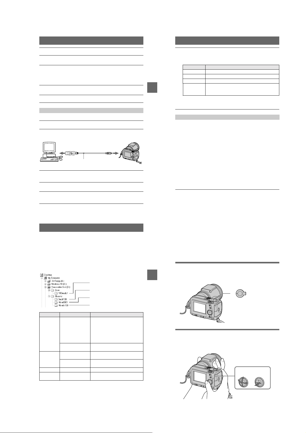
Image file storage destinations
and image files
Image files recorded with y our camera are grouped in folder s by recording mode.
The meanings of the file names are as follows.
within the range from 0001 to 9999.
For Windows 98 users (The drive recognizing the camera is
“D.”)
Folder containing stil l image data
Folder containing E-MAIL mode and TIFF
mode image data
Folder containing movi ng image data
Folder containing VOICE mode audio data
Folder File Meaning
100msdcf DSC0
TXT0
Imcif100 DSC0
DSC0
Moml0001 MOV0
Momlv100 DSC0
The numerical portions of the following files are the s ame.
— A small-size image file recorded in E-MAIL mode and its corresponding image file
— An unc ompressed image file recorded in TIFF mode and its corresponding image file
— A n au dio file rec or de d in VOICE mode and its cor responding image file
.JPG•Still image file recorded normally
ssss
ssss
ssss
ssss
ssss
ssss
•
•
•
.GIF•Still image file recorded in TEXT mode
.JPG•Small-size image file recorded in E-
.TIF•Uncompressed image file recorded in
.MPG•Moving image file recorded norma lly
.MPG•Audio file recorded in VOICE mode
stands for any number
ssss
Still image file recorded in E-MAIL
mode (page 38)
Still image file recorded in TIFF mode
(page 39)
Still image file recorded in VOICE
mode (page 38)
(page 39)
MAIL mode (page 38)
TIFF mode (page 39)
(page 38)
27
28
Advanced operations
Before performing advanced
operations
This section describes the basic control methods that are frequently used for
“Advanced operations”.
How to use the MODE selector
The MODE selector selects whether you can use yo ur camera to record or to play
BB
B
B
Playback
back and edit images. Se t the selector as follows before starting t o operate your
camera.
PLAY
STILL
MOVIE
PLAY: To play back or edit images
STILL: To record still images and
voice memos
MOVIE: To record moving images
How to use the control button
The control button is used to select the indicators, images and menus appearing on
the LCD screen of your camer a. The operation methods that are frequently used for
“Advanced operations” are described below.
Select Enter (OK)
29
30
1-7
Page 14
Turning on/off the operation buttons (menu bar) on the LCD screen
Press v to display the menu bar
on the LCD screen.
How to change the menu settings
Some of the advanced operations for your camera are executed by selecting menu
items displayed on the LCD screen with the control button.
Press V to clear the menu bar
from the LCD screen.
Note
You cannot clear the menu bar during INDEX screen display (page 46).
Selecting items and images on the LCD screen
Press v/V/b/B on the
1
control button to select the
item you want to set or the
image you want to display.
The color of the selected item or
the border of the selected image
changes from blue to yellow.
Press the center z to enter
2
the item.
Repeat steps 1 and 2 to execute
each function.
The “Advanced operations” section of this manual refers to selecting and
entering items by the above procedure as “Select [(item name)].”
Menu bar
31
MODE selector
Before performing advanced operations
Press v on the control button to display the menu bar.
1
The menu bar appears as follows according to the setting of the MODE
selector.
MOVIE/STILL PLAY (single mode) PLAY (INDEX mode)
Select the desired item with v/V/b/B on the
2
control button, then press the center z.
The color of the selected item changes from blue to
yellow, and when you press the center z, the modes
that can be set for that item are displayed.
Select the desired mode with v/V/b/B on the control butto n , then
3
press the center z.
To clear the menu
Press V on the control butto n un til the LCD screen returns to the me nu bar display in
step 1. To clear the menu bar, press V again.
32
Menu settings
Menu items that can be modi fied differ depe ndi ng on the setting of the MODE
selector. The LCD screen shows only the items you can operate at the moment. Initial
settings are indicated wi th x.
(SELF TIMER)
Records with the self-timer (page19).
EFFECT
Item Setting Description MODE
P.EFFECT SOLARIZE
DATE/
TIME
FILE
FORMAT OK Formats a “Memory Stick.” MOVIE
POS.
SENSOR
FILE
NUMBER
B&W
SEPIA
NEG.ART
OFF
x
DAY&TIME
DATE
OFF
x
Item Setting Description MODE
CANCEL Cancels formatting of a “Memory
ON Plays back images recorded with the
OFF When this camera may be subject to
x
SERIES Assigns numbers to files in sequence
NORMAL Resets the file numbering each time the
x
Sets the image special effects (page 45). MOVIE
Sets whether to insert the date and time
into the image (page 44).
Stick.”
camera on its side (vertical images) as
horizontal images. This function does
not work for images recorded in TEXT
mode.
vibration such as when you record
images from inside a moving car, set
this to OFF to prevent improper
horizontal/vertical judgement.
even if the “Memory Stick” is changed.
“Memory Stick” is changed.
selector
STILL
STILL
selector
STILL
PLAY
STILL
MOVIE
STILL
Item Setting Description MODE
IMAGE
SIZE
REC MODE TIFF Records a TIFF (uncompressed) file in
Before performing advanced operations
REC TIME
SET
ROTA TE
(in single
mode only)
SLIDE
SHOW
(in single
mode only)
PRINT
MARK
PROTECT ON Protects images against accident al
2240×1680
x
1856×1392
1856 (3:2)
1280×960
640×480
320 (HQ)
320×240
160×112
x
TEXT Records a GIF file in black-and- w hi t e.
VOICE Records an audio file (with still image)
E-MAIL Records a small-size (320×240) JPEG
NORMAL Records a JPEG file in the selected
x
15 sec
10 sec
5sec
x
INTERVAL
REPEAT Repeats the slide show.
START Starts the slide show.
CANCEL Cancels the slide show settings and
ON Marks the still images to be printed
OFF Unmarks the print mark of the still
x
OFF Releases protection of images against
x
Selects the image size when recording
still images.
Selects the MPEG image size when
recording moving images.
addition to the JPEG file.
in addition to the JPEG file.
file in addition to the selected image
size.
image size.
Adjusts the recording time for moving
images.
Rotates the still image. PLAY
—
Sets the slide show interval.
3 sec/5 sec/10 sec/30 sec/1 min
x
ON/OFF
x
execution.
(page 54).
images.
erasure (page 50).
accidental erasure.
selector
STILL
MOVIE
STILL
MOVIE
PLAY
PLAY
PLAY
33
34
1-8
Page 15
CAMERA
Item Setting Description MODE
DIGITAL
ZOOM
SHARPNESS
FLASH
LEVEL
EXPOSURE +2.0 EV to
TOOL
COPY OK Copies an image (page 52). PLAY
RESIZE
(in single
mode only)
SETUP
DEMO
ON Uses digital zoom. STILL
x
OFF Does not use digital zoom.
+2 to –2 Adjusts the sharpness of the image.
HIGH Makes the flash level higher than
NORMAL Normal setting.
x
LOW Makes the flash level l ower than normal.
–2.0 EV
Item Setting Description MODE
CANCEL Cancels copying of the image.
2240×1680
1856×1392
1280×960
640×480
CANCEL
x
Item Setting Description MODE
ON/STBY
x
OFF
appears on the LCD screen except
when set to 0.
normal.
Adjusts the exposure. MOVIE
Changes the recorded still image size
(page 52).
Displayed only when you us e t he AC
power adaptor in MOVIE or STILL
mode. When ON is selected, a
demonstration will start if you do not
operate your camera for about
10 minutes. To stop the demonstration,
turn off your camera. Selec t ON to make
the demonstration appear again.
STILL
STILL
STILL
PLAY
MOVIE
STILL
selector
selector
selector
Item Setting Description MODE
VIDEO
OUT
LANGUAGE
CLOCK
SET
BEEP SHUTTER Turns off the beep only. (The shutter
Before performing advanced operations
LCD
BRIGHT
INDEX*
Displays six images at a time (PLAY (INDEX) mode) (page 46).
DELETE
OK Deletes the displayed image. PLAY
CANCEL Cancel s deleting of the image.
(RETURN)**
3
Returns to PLAY (single) mode.
Displayed only in PLAY (single) mode.
∗
Displayed only in PLAY (INDEX) mode.
∗∗
NTSC Sets the video output signal to NTSC
x
PAL Sets the video output signal to PAL
/
ENGLISH Displays the menu items in English. MOVIE
x
ON Turns on the beep/shutter sound (when
x
OFF Turns off the beep/shutter sound.
Setting Description MODE selector
mode (North American countries, Japan,
etc.).
mode (European countries, etc.).
/JPN Displays the menu items in Japanese.
Sets the date and time (page 13). MOVIE
—
sound is heard when you press the
shutter button.)
you press the control button/
button).
Adjusts the LCD screen brightness
using the +/– buttons on the LCD
screen. This has no effect on the
recorded images.
shutter
selector
MOVIE
STILL
PLAY
STILL
PLAY
STILL
PLAY
MOVIE
STILL
PLAY
MOVIE
STILL
PLAY
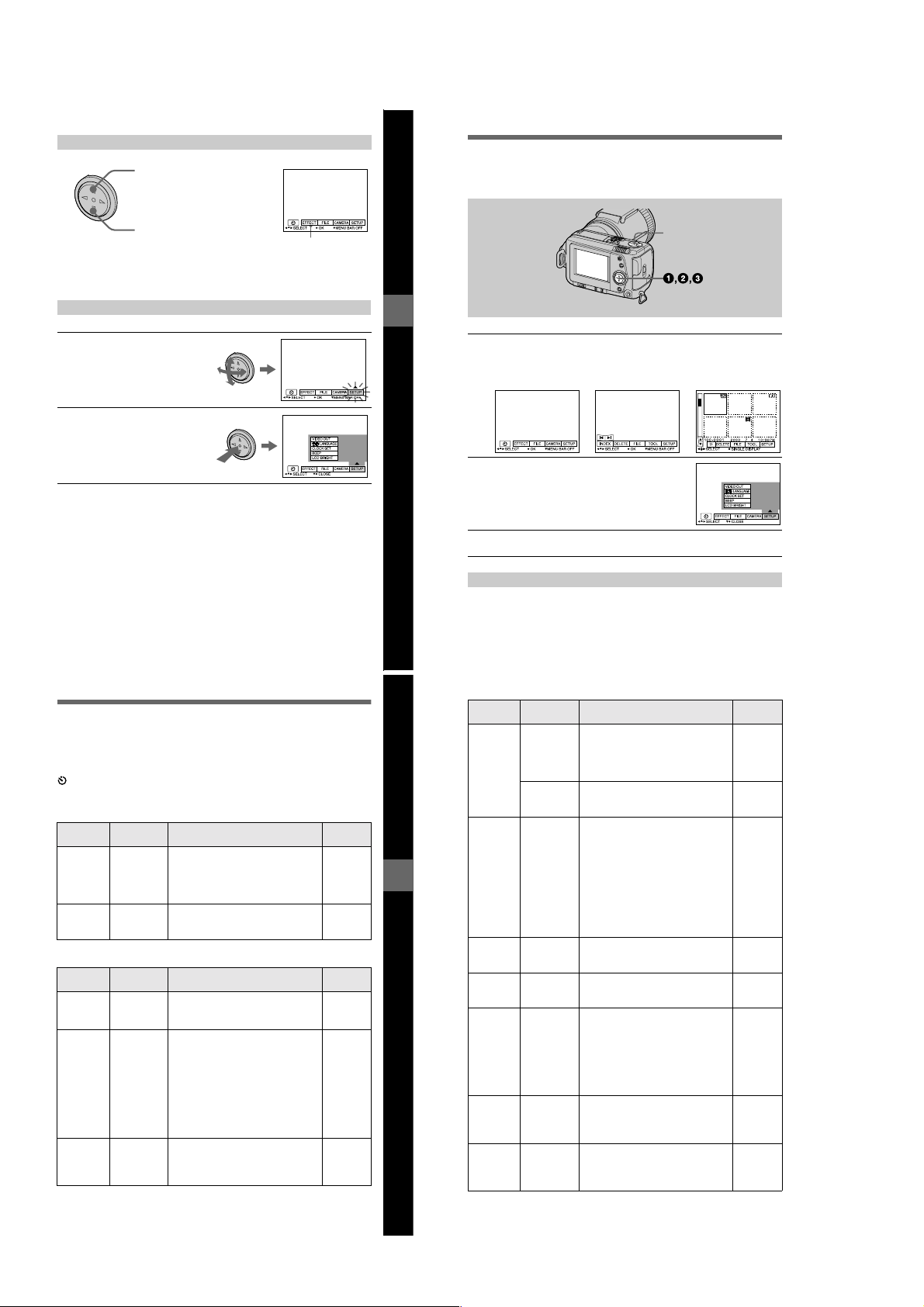
Various recording
B
Setting the image size
(IMAGE SIZE)
1
2,3
1
Set the MODE selector to
MOVIE or STILL.
2
Select [FILE] and then
[IMAGE SIZE] from the menu.
3
Select the desired image
size.
Still image sizes
2240×1680, 1856×1392,
1856 (3:2)*, 1280×960, 640×480
The image is recorded in 3:2 size to
∗
match the printing paper size ratio of
3:2.
Moving image sizes
320 (HQ*), 320×240, 160×112
High Quality mode
∗
35
The number of images or the time
that you can record on a “Memory
Stick” (8 MB):
Image size Number of images or
2240×1680 Approx. 4
1856×1392 Approx. 6
1856 (3:2) Approx. 6
1280×960 Approx. 12
640×480 Approx. 118
320 (HQ) Approx. 20 (15**) sec.
320×240 Approx. 85 (15**) sec.
160×112 Approx. 345 (60**) sec.
When [REC MODE] is set to
∗
[NORMAL].
Numbers in parentheses indicate the
∗∗
maximum recording time during
continuous recording.
time*
BB
B
B
Various recording
36
Recording still
images for e-mail (EMAIL)
E-MAIL mode records a small-size
(320×240) image at the same time as a
still image. Small-size images are
convenient for e -mail t rans missio n, etc .
1
3
2
1
Set the MODE selector to
STILL.
2
Select [FILE], [REC MODE],
and then [E-MAIL] from the
menu.
3
Record the image.
The number of images that you can
record on a “Memory Stick” (8 MB)
in E-MAIL mode:
Image size Number of images
2240×1680 Approx. 4
1856×1392 Approx. 5
1856 (3:2) Approx. 5
1280×960 Approx. 12
640×480 Approx. 95
To return to normal
recording mode
Select [NORMAL] in step 2.
Adding audio files to
still images (VOICE)
1
3
2
1
Set the MODE selector to
STILL.
2
Select [FILE], [REC MODE],
and then [VOICE] from the
menu.
3
Record the image.
If you press and release the shutter
button, sound is recorded for
5 seconds.
If you hold down the shutter
button, sound is recorded until you
release the shutter button for up to
40 seconds.
The number of images that you can
record on a “Memory Stick” (8 MB)
in VOICE mode (when recording
sound for five seconds):
Image size Number of images
2240×1680 Approx. 4
1856×1392 Approx. 5
1856 (3:2) Approx. 5
1280×960 Approx. 11
640×480 Approx. 56
To return to normal
recording mode
Select [NORMAL] in step 2.
37
38
1-9
Page 16
Recording text
documents (TEXT)
Text is recorded in black and wh i te
GIF format to provide a clearer image.
1
3
2
1
Set the MODE selector to
STILL.
2
Select [FILE], [REC MODE],
and then [TEXT] from the
menu.
3
Record the image.
The number of images that you can
record on a “Memory Stick” (8 MB)
in TEXT mode:
Image size N umber of images
2240×1680 Ap prox. 10 to 110
1856×1392 Ap prox. 20 to 140
1856 (3:2) Approx. 20 to 160
1280×960 Approx. 40 to 228
640×480 Approx. 160 to 727
To return to normal
recording mode
Select [NORMAL] in step 2.
Notes
•
If the subject is not evenly illuminated, you
may be unable to record a clear image.
•
Writing and reading data takes mor e ti me
than in normal recording.
Recording
uncompressed
images (TIFF)
This mode simultaneously records still
images in both TIFF format
(uncompressed) and JPEG format
(compressed).
1
3
2
1
Set the MODE selector to
STILL.
2
Select [FILE], [REC MODE],
and then [TIF F] from the
menu.
3
Record the image.
The number of images that you can
record on a “Memory Stick”
(16 MB) in TI FF m ode:
Image size Number of images
1856×1392 Approx. 1
1856 (3:2) Approx. 1
To return to normal
recording mode
Select [NORMAL] in step 2.
Notes
•
JPEG images are recorded in the image
size selected by the [IMAGE SIZE] menu.
TIFF images are recorded in [1856×1392]
size other than when [1856 (3:2)] is
selected.
•
Writing data takes more time than in
normal recording.
•
The supplied “Memory Stick” (8 MB)
does not have sufficient capacity to r eco r d
uncompressed images.
BB
B
B
Various recording
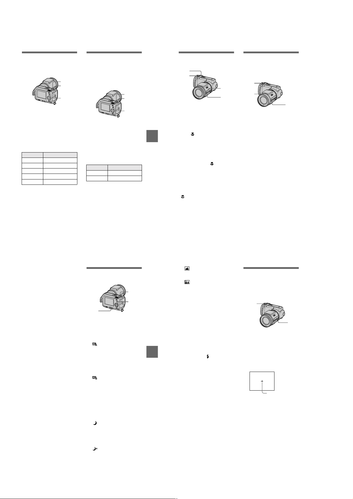
Recording images in
macro
3
1
3
2
1
Set the MODE selector to
MOVI E or STILL.
2
Set FOCUS AUTO/MANUAL
to AUTO.
3
Set the zoom to W side and
then press MACRO.
The (macro) indicator appears on
the LCD screen. You can shoot a
subject that is about 13/16 inches
(2 cm) away from the lens surface in
macro mode.
To return to normal
recording mode
Press MACRO again. disappears
from the LCD screen.
Notes
•
Y ou cannot record images in macro with
the following PROGRAM AE modes.
— L and sc ap e m ode
— Panfocus mode
•
You cannot record images in macro when
appears on the LCD screen.
•
When you shoot a subject that is about
13/16 inches (2cm) away from the lens
surface, the edges of the LCD screen
image may appear distorted.
Focusing manually
Normally the focus is automatically
adjusted. This function is useful when
the auto focus does not work well such
as in dark places.
1
3
2
1
Set the MODE selector to
MOVIE or STILL.
2
Set FOCUS AUTO/MANUAL
to MANUAL.
The 9 (manual focus) indicator
appears on the LCD screen.
3
Turn the focus ring to achieve
a sharp focus.
When recording still images, the
LCD screen image is zoomed to
2×* and the focus mode indicator
is displayed. When a sharp focus is
achieved, the image returns to
normal and the 9 (manual focus)
indicator changes from yel l ow to
white. When recording moving
images, the image is not zoomed.
You can adjust the focus distance
from
13/16 inches (
(infinite).
When using digital zoom, the LCD
∗
screen image is zoomed to slightly
less than 2x.
To reactivate auto focusing
Set FOCUS AUTO/MANUAL to
AUTO.
2cm) to ∞
Notes
•
The focus mode indicator is approximate,
and should be used as a reference.
•
The focus mode indicator is not displayed
correctly when using a conversion lens.
•
When the zoom lever is set to the T side,
your camera may not focus on subjects
closer than about 2 5/8 feet (80 cm). In
these cases, the focus mode indicator
flashes. Move the zoom le ver to ward the W
side until the focus mode indica tor stops
flashing.
•
You cannot focus manually in PROGRAM
AE Panfocus mode.
Using the PROGRAM
AE function
1
2
+/–
1
Set the MODE selector to
MOVI E or STILL.
2
Press PROGRAM AE
repeatedly t o select the
desired PROGRAM AE mode.
Aperture priority mode
Makes the subject stand out
against an unclear background or
makes both the subject and the
background stand out clearly.
Press +/– repeatedly to select an
aperture valu e i n 7 st eps from F 2.8
to F8.
Shutter speed priority
mode
Records a sharp picture o f a fas tmoving subject or the flow of
motion of a moving subject.
Press +/– repeatedly to select a
shutter speed in 19 steps from 8”
to 1/1000 when recording a still
image and in 13 steps from 1/8 to
1/1000 when recording a moving
image.
Twilight mode
Suppresses the washed-out color
of a bright subject i n a dark place
so that you can record the subject
without losing the dark
atmosphere of the surroundings.
Twilight plus mode
Increases the effectiveness of the
twilight mode function.
39
41
BB
B
B
Various recording
40
Landscape mode
Focuses only on a distant subject
to record landscapes, etc.
Panfocus mode
Changes the focus quickly and
simply from a close subject to a
distant subject.
To cancel PROGRAM AE
Press PROGRAM AE repeatedly until
the indicator on the LCD screen goes
out.
Notes
•
You cannot select F2.8 in aperture priority
mode when the zoom is set to the T side.
•
You can focus only on distant subjects in
Landscape mode.
•
In Panfocus mode, the zoom position and
focus are fixed.
•
When you record in the Twilight plus
mode, we recommend that you use a tripod
to prevent shaking.
•
Set the forced flash when you use the
flash in the following modes:
–
Twilight mode
–
Twilight plus mode
–
Landscape mode
•
You cannot use the PROGRAM AE
function when [REC MODE] is set to
[TEXT].
•
If the setting is not appropriate in a perture
priority mode and shutter priority mode,
the setting value indicator on the LCD
screen flashes when you press the shutter
button halfway down. In this case, reset the
value.
•
If you set a slow shutter speed in twilight
plus mode and shutter speed priority mode,
the noise may increase.
42
Using the spot lightmetering mode
Use this mode when there is backlight
or when there is strong contrast
between the subject and the
background, etc.
1
2
1
Set the MODE selector to
MOVIE or STILL.
2
Press SPOT METER to
display the spot lightmetering cross hair.
Position the point you want to
record on the spot light-metering
cross hair.
LCD screen
Spot light-metering
cross hair
1-10
Page 17
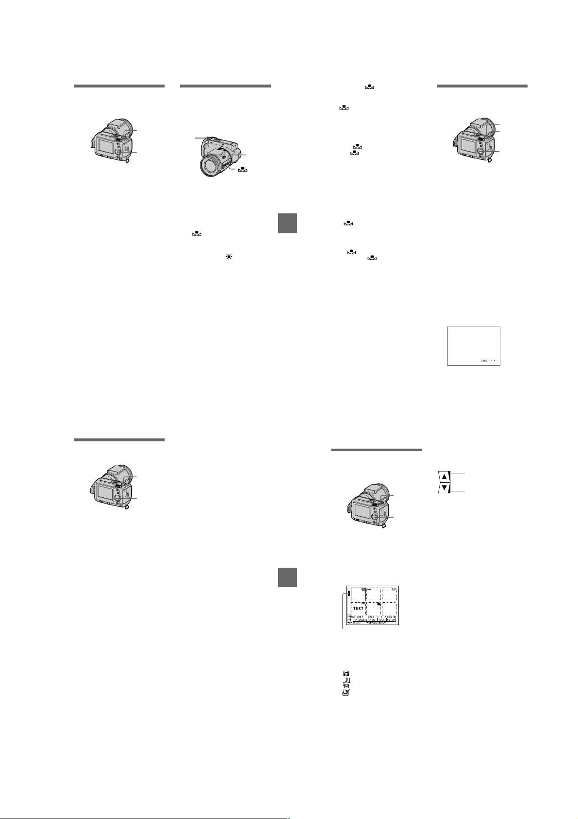
Adjusting the
exposure
(EXPOSURE)
1
2,3
1
Set the MODE selector to
MOVIE or STILL.
2
Select [CAMERA] and then
[EXPOSURE ] from the menu.
3
Select the desired exposure
value.
Adjust the exposure value while
checking the brightness of the
background. You can select values
ranging from +2.0 EV to –2.0 EV
in steps of 1/3EV.
Note
The exposure may not be adjusted properly
when the subject is extremely bright or dark,
or when using the flash.
Adjusting the white
balance (WHITE
BALANCE)
Normally the white balance is
automatically adjusted.
1
2
1
Set the MODE selector to
MOVI E or STILL.
2
Press WHT B AL repeat edly t o
select the desired white
balance mode.
One-push white balance
()
Adjusts the white balance
depending on the light source
OUT DOOR ( )
Recording a sunrise/sunset, night
scene, neon signs, or fireworks
IN DOOR (n)
•
Places where the lighting
condition changes quickl y
•
Under bright lighting such as
photography studios
•
Under sodium or mercury lamps
AUTO (No indicator)
Adjusts the white balance
automatically
BB
B
B
Various recording
To set the (One-push
white balance) button
1 Press WHT BAL repeat edly until
appears.
2 Place a white object such as paper
under the same light conditions as
you are going to record, and record
the white object so that it fills the
entire frame of your cam era.
3 Press .
The indicator starts to flash
quickly. Once the white balance is
set, the indicator stops flashing.
To reactivate auto
adjustment
Select [AUTO] in step 2.
Notes
•
Select [AUTO] when record i ng und er
fluorescent lighting.
•
The indicator means:
Slow flashing: white balance is not set.
Quick flashing: white balance is being
adjusted.
Lit steady: white balance has been set .
•
If the indicator keeps flashing even
when you press , record in automatic
white balance mode.
Recording the date
and time on the still
image (DATE/TIME)
1
4
2,3
1
Set the MODE selector to
STILL.
2
Select [EFFECT] and then
[DATE/TIME] from the menu.
3
Select the date and time
setting.
DAY&TIME
The date, hour and minutes are
imposed onto the image.
DATE
The year, month and day are
imposed onto the image.
OFF
The date and time are not imposed
onto the image.
4
Record the image.
The date and time are not
displayed during recording.
The date and time are di s played
when playing back images.
Enjoying picture
effects (P.EFFECT)
1
2,3
1
Set the MODE selector to
MOVIE or STILL.
2
Select [EFFECT] and then
[P.EFFECT] from the menu.
3
Select the desired mode.
SOLARIZE
The light contrast is clearer and the
picture looks like an illustration.
B&W
The picture is monochrome (black
and white).
SEPIA
The picture is colored like an old
picture.
NEG.ART
The color and brightn ess of the
picture are reversed.
To cancel picture effect
Select [OFF] in step 3.
43
BB
B
B
Various recording
44
Various playback
B
Playing back six
images at once
(INDEX)
1
Set the MODE selector to
PLAY.
2
Select [INDEX] on the LCD
screen.
Six images are displayed at once
(index screen).
This shows the position of the
currently displayed images relative
to all the recorded images.
The following marks are displayed
on each image according to the
image type and settings.
: Moving image file
: Voice memo file
: E-mail file
: Print mark
-
: Protect mark
TEXT: Text mark
TIFF: TIFF mark
(No mark): Normal recording (no
settings)
To display the next
(previous) index screen
Select v/V at the lower left of t he LCD
screen.
Displays the prev ious
index screen
1
2
To return to n ormal playback
(single image)
•
•
Note
You cannot display images recorded in
TEXT mode on the INDEX screen.
Displays the nex t index
screen
Select the desired image w i t h the
control button.
Select [3] (RETURN).
45
46
1-11
Page 18
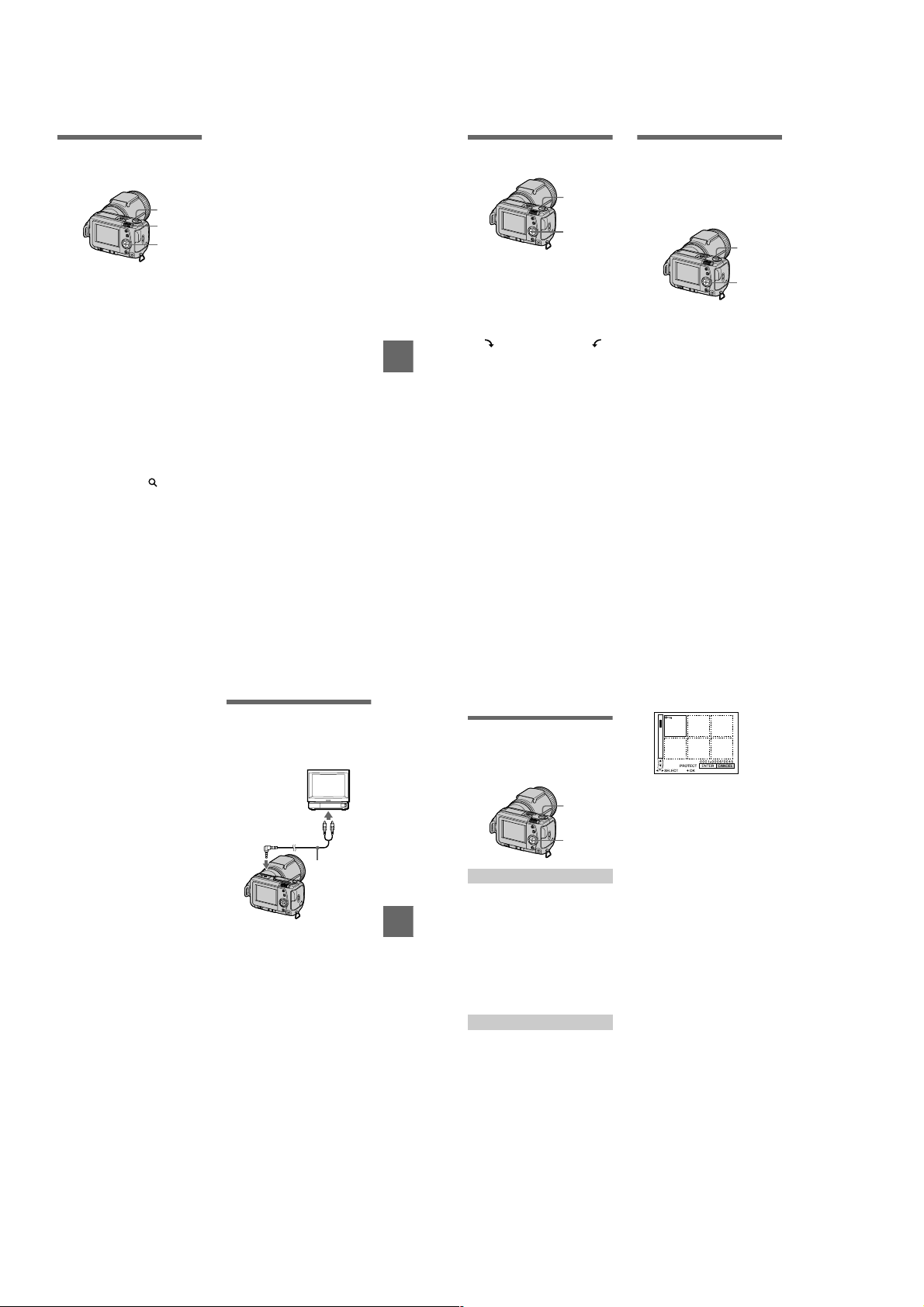
Enlarging a part of
the still image (Zoom
and trimming)
1
3
2,4
1
Set the MODE selector to
PLAY.
2
Display the image to be
enlarged.
3
Zoom in/out the image with
the zoom lever.
The zoom scaling indica tor
appears on the LCD screen.
4
Press the control button
repeatedly to select the
desired part of the image .
: The image moves downward
v
: The image moves upward
V
: The image moves rightward
b
: The image moves leftward
B
To return to the normal size
Zoom out with the zoom leve r until the
zoom scaling indicator ( ×1.1)
disappears from the screen, or simply
press z.
To record an enlarged image
(trimming)
1Enlarge the image.
2Press the shutter button. The image
is recorded at 640×480 size, then the
display returns to the image display
before enlargement.
Notes
•
You cannot trim images recorded in TEXT
mode or uncompressed images.
•
The maximum zoom magnification is 5
the original image, re g ard l ess of the image
size.
•
The picture quality of trimmed images
may deteriorate.
•
The original picture remains e ven after
trimming.
•
The trimmed image is re corded as the
newest file.
47
Rotating a still image
×
(ROTATE)
1
Playing back the
images in order
(SLIDE SHOW)
This function is usef ul fo r chec king the
recorded images or for presentations,
etc.
2,3,4
1
1
Set the MODE selector to
PLAY.
2
Display the image to rotate.
3
Select [FILE] and then
[ROTATE] from the menu.
4
Rotate the image clockwise
or counterclockwise ,
then select [RETURN].
BB
B
B
Various playback
Notes
•
Y ou may no t be able to rotate images
recorded with other equipment.
•
Also, when viewing images on a personal
computer, the image rotation information
may not be reflected depending on the
application software.
•
You cannot rotate protected or
uncompressed images, or images recorded
in TEXT mode.
1
Set the MODE selector to
PLAY.
2
Select [FILE] and then [SLIDE
SHOW] from the menu.
Set the following items.
INTERVAL
1 min (one minute), 30 sec
(30 seconds), 10 sec (10 seconds),
5 sec (5 seconds) , 3 sec
(3 seconds)
REPEAT
ON: Plays back images in a
continuous loop until
[RETURN] is selected.
OFF: After all images have been
played back, the slide show
ends.
3
Select [START] with the
control button.
The slide show begins.
To cancel the slide show
Select [CANCEL ] in step 2 or 3.
To skip to the next/previous
image during slide show
playback
Select
at the lower left of the
"b/B"
LCD screen.
2,3
48
Note
The [INTERVAL] setting time is
approximate, and may vary depending on
the played back image size or other factors.
Viewing images on a
TV screen
Before connecting you r ca mera, be
sure to turn off the TV.
Set the TV/VIDEO
switch to “VIDE O.”
to A/V OUT jack
A/V connecting
cable (supplied)
1
Connect the A/V connecting
cable to the A/V OUT jack of
your camera and to the
audio/video input jacks of the
TV.
If your TV has stereo type audio
input jacks, co nnect the audi o pl ug
of the A/V connecting cable to the
Lch jack.
2
Turn on the TV, then start
playback on your camera.
The playback image appears on
the TV screen.
Note
You cannot use a TV that has an antenna
(aerial) connector only.
49
Editing
B
The selected images are p ro tected.
Preventing accidental
erasure (PROTECT)
The - (protect) indicator ap pears on
protected images.
1
1,2,3
To release protection
If you selected [ALL] in step 2, select
[OFF]. If you selected [SELECT] in
step 2, select the images to unprotect
with the control button, then select
[ENTER].
In single mode
1
Set the MODE selector to
PLAY, then disp l ay the image
to protect.
2
BB
B
B
Various playback
Select [FILE], [PROTECT],
and then [ON] from the menu.
The displayed imag e i s protected
and - appears.
To release protection
Select [OFF] in step 2.
In INDEX mode
1
Set the MODE selector to
PLA Y, then display the INDEX
screen.
2
Select [FILE], [PROTECT],
and then [ALL] or [SELECT]
from the menu.
3
When you select [ALL]
Select [ON].
All the images recorded in
“Memory Stick” are protected.
When you select [SELECT]
Select all the images to prote ct
with the control button, then select
[ENTER].
50
1-12
Page 19
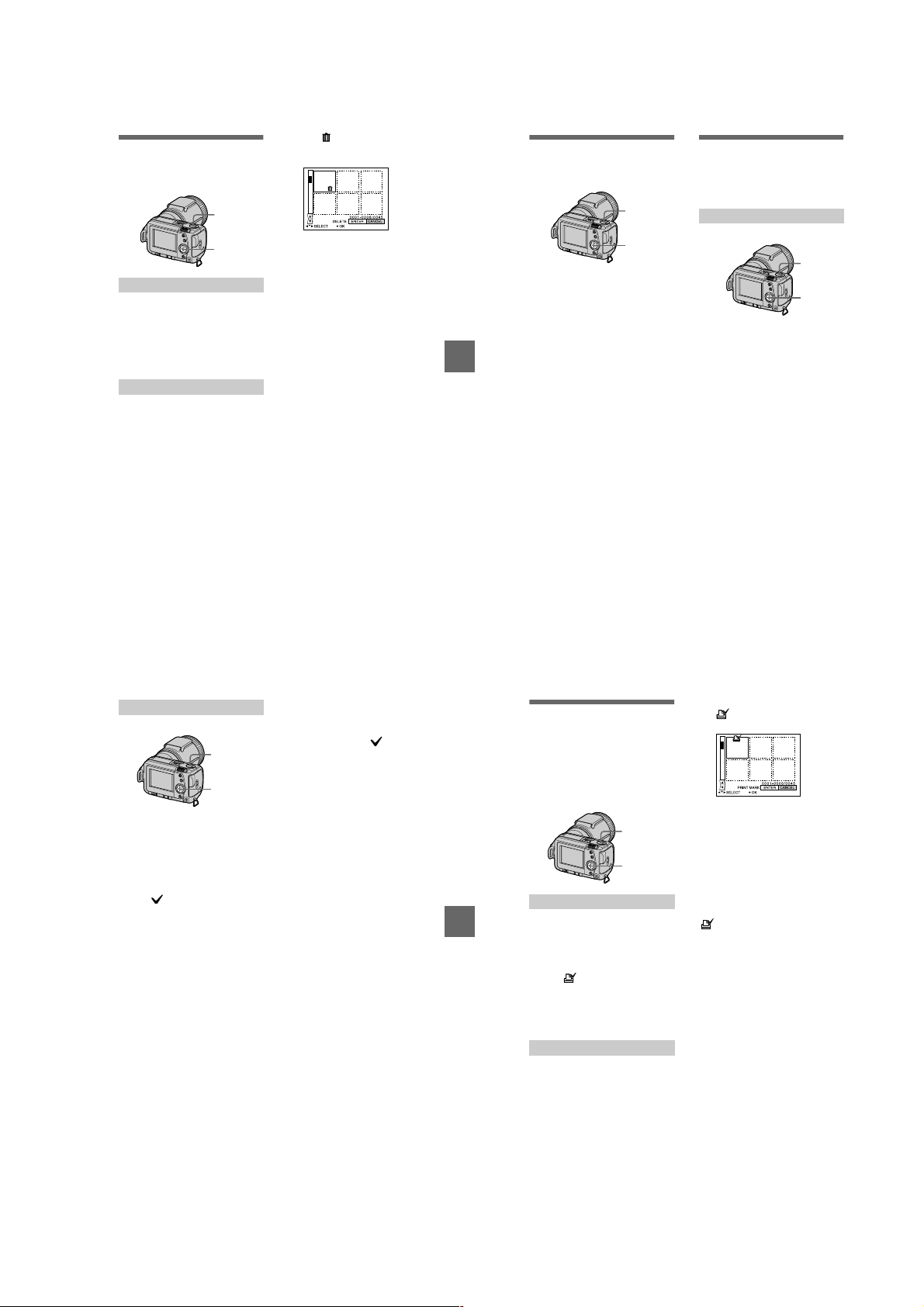
Deleting images
1,2
1
(DELETE)
You cannot delete protected files.
1
The (delete) indicator appears
on the selected images and these
images are deleted.
Changing the
recorded still image
size (RESIZE)
1
Copying images
(COPY)
You can copy images to another
“Memory Stick.”
In single mode
1,2,3
In single mode
1
Set the MODE selector to
PLAY, then display the image
to delete.
2
Select [DELETE] and then
[OK] from the menu.
The image is deleted.
In INDEX mode
1
Set the MODE selector to
PLAY, then disp la y th e IND EX
screen.
2
Select [DELETE] and then
[ALL] or [SELECT] from the
menu.
3
When you select [ALL]
Select [ENTER].
All unprotected images are
deleted.
When you select [SELECT]
Select all the images to del et e with
the control button, then select
[ENTER].
To cancel deleting
Select [CANCEL] in step 2 or 3.
Note
If there are files on the “Memo ry Stick” with
names having the same last 4 digits as the
file name of the image to be deleted, these
files are also deleted at the same time.
51
BB
B
B
Editing
1,2,3
1
Set the MODE selector to
PLAY and display the image
to resize.
2
Select [TOOL] and then
[RESIZE] from the menu.
3
Select the desired image
size.
2240×1680, 1856×1392,
1280×960, 640×480
The changed image is recorded,
then the display returns to the
image display before resizing.
To return to the original size
Select [CANCEL] in step 3.
Notes
•
You cannot change the size of images
recorded in TEXT mode or uncompressed
images.
•
When you change from a small size to a
large size, the picture quality deteriorates.
•
The original image is retained even after
resizing.
•
The resized image is recorded as the
newest file.
52
1
Set the MODE selector to
PLAY, then display the image
to copy.
2
Select [TOOL], [COPY], and
then [OK] from the menu.
“MEMORY STICK ACCESS”
appears.
3
When “CHANGE MEMORY
STICK” appears, eject the
“Memory Stick.”
“INSERT MEMORY STICK”
appears.
4
Insert the “Memory Stick” on
which to copy the image.
“RECORDING” appears. When
copying is completed,
“COMPLETE” appears.
To end copying, select [EXIT].
To copy the image to
another “Memory Stick”
Select [CONTINUE] and repeat steps
3
and 4.
In INDEX mode
1
1,2,3,4
1
Set the MODE selector to
PLAY, then disp la y th e IND EX
screen.
2
Select [TOOL], [COPY], and
then [SELEC T] from the
menu.
3
Select the image to copy.
The (select) indicator appears
on the image.
4
Select [ENTER].
“MEMORY STICK ACCESS”
appears.
5
When “CHANGE MEMORY
STICK” is disp lay ed, ejec t the
“Memory Stick.”
“INSERT MEMORY STICK”
appears.
6
Insert another “Memory
Stick.”
“RECORDING” appears. When
copying is completed,
“COMPLETE” appears.
To end co pying, select [EXIT].
To copy the image to
another “Memory Stick”
Select [CONTINUE] and repeat steps
5
and 6.
To cancel copying part-way
Change the MODE selector setting or
turn off the power.
Notes
•
You cannot copy uncompressed images.
•
You cannot copy images that are bigger
than 5 MB at once. If “NOT ENOUGH
MEMORY” appears or flashes on the
INDEX screen, cancel some images to
copy and try again.
•
After “COMPLETE” appears, if you
exchange the “Memory Stick” without
selecting “EXIT,” the same image is
copied again.
BB
B
B
Editing
Selecting still images
to print (PRINT MARK)
You can mark a print mark on still
images recorded with your camera.
This mark is convenient when you
have images printed at a shop that
conforms with the DPOF (Digital Print
Order Format) standard .
1
1,2,3,4
In single mode
1
Set the MODE selector to
PLAY and display the image
you want to print.
2
Select [FILE], [PRINT MARK],
and then [ON] from the menu.
The (print) mark is displayed
on the image.
To unmark the print mark
Select [OFF] in step 2.
In INDEX mode
1
Set the MODE selector to
PLA Y, then display the INDEX
screen.
2
Select [FILE], [PRINT MARK],
and then [SELECT] from the
menu.
3
Select the images to mark
with the control button.
4
Select [ENTER].
of the selected i mages change
from green to white .
To unmark selected print
marks
Select the image s t o unmark in step 3
with the control button, then select
[ENTER].
To unmark all the print
marks
Select [FILE], [PRINT MARK],
[ALL] and then [OFF] from the menu.
of all images are unmark ed.
Notes
•
You cannot mark moving images or images
recorded in TEXT mode.
•
If you mark an image recorded in TIFF
mode with a print mark, only the
uncompressed image is printed, and the
JPEG image recorded at the same time is
not printed.
53
54
1-13
Page 20
Additional information
Precautions
On cleaning
Cleaning the LCD screen
Wipe the screen surface with a cleaning
cloth (not supplied) or a LCD cleaning kit
(not supplied) to remove fingerprints, dust,
etc.
Cleaning the camera surface
Clean the camera surface with a soft cloth
slightly moistened with water, then wipe the
surface dry. Do not use any type of solvent
such as thinner, alcohol or ben zen e as this
may damage the finish or the casing.
After using your camera at the
seashore or other dusty locations
Clean your camera carefully. Otherwise, the
salty air may corrode the metal fittings or
dust may enter the inside of your camera,
causing a malfunction.
Note on operating
temperature
Your camera is designed for use between the
temperatures of 32°F and 104°F (0°C and
40°C). Recording in extremely cold or hot
places that exceed this range is not
recommended.
On moisture condensation
If the camera is brought directly from a cold
to a warm location, or is placed in a very
damp room, moisture may condense inside
or outside the camera. Sho uld t his occur, the
camera will not operate properly.
Moisture condensation occurs
easily when:
•
The camera is brought fr om a cold lo catio n
such as a ski slope into a warmly heated
room.
•
The camera is taken from an airconditioned room or car interior to the hot
outdoors, etc.
How to prevent moisture
condensation
When bringing the camera from a cold place
to a warm place, seal the camera in a plastic
bag and allow it to adapt to conditions at the
new location over a period of time (about an
hour).
If moisture condensation occurs
Turn off the camera and wait about an hour
for the moisture to evaporate. No te that if
you attempt to record with moi sture
remaining inside the lens, you will be unable
to record clear images.
On AC power adaptor
•
Unplug the unit from the wall outlet
(mains) when you are not using the unit for
a long time.
•
To disconnect the po wer cord (m ains lead ),
pull it out by the plug. Never pull the
power cord (mains lead) itself.
•
Do not operate the unit with a damaged
cord or if the unit has been dropped or
damaged.
•
Do not bend the power cord (mains lead)
forcibly, or pl ace a hea vy obj ect on it . This
will damage the cord and may cause fire or
electrical shock.
•
Prevent metallic objects from co ming into
contact with the metal parts of the
connecting section. If this happens, a short
may occur and the unit may be damaged.
•
Always keep metal contacts clean.
•
Do not disassemble the unit.
•
Do not apply mechanical shock or drop the
unit.
•
While the unit is in use, particularly during
charging, keep it away from AM receivers
and video equipment. AM reception and
video operation are disturbed.
•
The unit becomes warm during use. This is
not a malfunction.
•
Do not place the unit in locations that are:
—Extremely hot or cold
—Dusty or dirty
—Very h u m i d
—Vibrating
On battery pack
•
Use only the specified charger with the
charging function.
•
To prevent accident from a short circuit, do
not allow metal objects to come into
contact with the battery termin al s.
•
Keep the battery pack away fro m fire.
•
Never expose the battery pack to
temperatures above 140°F (60°C), such as
in a car parked in the sun or under direct
sunlight.
•
Keep the battery pack dry.
•
Do not expose the battery pack to any
mechanical shock.
•
Do not disassemble nor modify the battery
pack.
•
Install the battery pack to the camera
securely.
•
Charging while some capacity remains
does not affect the original battery
capacity.
If any problem occurs, unplug your camera
and contact your nearest Sony dealer.
On internal rechargeable
button battery
Additional information
This camera has an internal rechargeable
button battery for maintaining the dat e and
time and other settings regardless of whether
the power is on or off. This rechargeable
button battery is constantly charged as long
as you are using the camera. However, if
you use the camera for only short periods it
discharges gradually, and if you do not use
the camera at all for about half a year it
becomes completely discharged. In this
case, be sure to charge this rechargeable
button batte ry before using the camera.
However, even if this rechargeable button
battery is not charged, you can still use the
camera as long as you do not record the date
and time.
Charging method
Connect the camera to a wall outlet (mains)
with the AC power adaptor/charger, or
install a charged battery pack, and leave the
camera for 24 hours or more with the
POWER switch set to OFF.
On “Memory Sticks”
“Memory Stick” is a new compact, portable
and versatile IC recording medium with a
data capacity that exceeds a floppy disk.
“Memory Stick” is specially designed for
exchanging and sharing digital data among
“Memory Stick” compatible products.
Because it is removable, “Memory Stick”
can also be used for external data storage.
There are two types of “Memory Sticks”:
general “Memory Sticks” and “MagicGate
Memory Sticks” that are equipped with the
MagicGate* copyright protection
technology.
You can use both types of “Memory Stick”
with your camera. However, because your
camera does not support the MagicGate
standards, data recorded with your c amera is
not subject to MagicGate copyright
protection.
MagicGate is copyright protection
∗
technology that uses encryption
technology.
Notes
•
Do not remove the “Memory Stick” while
reading or writing data.
•
Data may be damaged if:
—you remove the “Memory Stick” or turn
off your camera while reading or
writing data.
—you use the “Memory Stick” in a
location subject to the effects of static
electricity or noise.
•
Do not attach any other mater i a l than the
supplied label on th e labeling position .
•
Attach the label so that it does not stick out
from the proper attachment location.
•
When you carry or store the “Memory
Stick,” put it in its supplied case.
•
Do not touch the terminals of a “Memory
Stick” with your hand or a metal object.
•
Do not strike, bend or drop the “Memory
Stick.”
•
Do not disassemble or modify the
“Memory Stick.”
•
Do not allow the “Memory Stick” to get
wet.
“Memory Stick”, , “MagicGate
Memory Stick” and are trademarks of
Sony Corporation.
“MagicGate” and are
trademarks of Sony Corporation.
Using your camera
abroad
Power sources
You can use your camera in any
country or area with the supplied
battery charger within 100 V to 240 V
AC, 50/60 Hz. Use the supplied AC
power adaptor
depending on the design o f the wall
outlet (mains)
Watching the playback picture on
TV
If you want to view the playback
picture on a TV, you need a TV having
a video input jack and a video
connecting cable.
The color system of the TV mus t be
the same as that of your digital still
camera. TV color systems differ from
country to country. Check the
following list:
NTSC system countries
Bahama Islands, Bolivia, Canada,
Central America, Chile, Columbia,
Ecuador, Jamaica, Japan, Korea,
Mexico, Peru, Surinam, Taiwan, the
Philippines, t he U.S.A., Venezuela, etc.
AC-VF10
[a]
, if necessary,
[b]
.
PAL system countries
Australia, Austria, Belgium, China,
Denmark, Finland, Germany, Great
Britain, Holland, Hong Kong, Italy,
Kuwait, Malaysia, New Zealand,
Norway, Portugal, Singapore, Spain,
Sweden, Switzerland, Th ai la nd, etc.
PAL-M system country
Brazil
PAL-N system countries
Argentina, Paraguay, Uruguay
SECAM system countries
Bulgaria, Czech Republic, France,
Guiana, Hungary, Iran, Iraq, Mon aco,
Poland, Russia, Slovak Republic,
Ukraine, etc.
55
56
Troubleshooting
If you experience trou ble with your camera, first ch eck the following items. Should
your camera still n ot oper at e pr oper ly a fte r yo u ha v e ma de th ese ch eck s, co nsu lt yo ur
Sony dealer or local authorized Sony service facility. If code displays (C:ss:ss)
appear on the LCD screen, the self-diagnosis display function is working (page 63).
Symptom Cause and/or Solution
Your camera does not
work.
Your camera cannot
Additional information
record images.
The picture is out of focus. •Your camera is not in macro recording mode when
The resizing functi on doe s
not work.
You cannot display a print
mark.
The picture is noisy.
•
You are not using an “InfoLITHIUM” batter y pack.
t Use an “InfoLITHIUM” battery pack (page 9).
•
The battery level is low (the E indicator appears
on the LCD screen).
t Charge the battery pack (page 9).
•
The AC power adaptor is not connected securel y.
t Connect it firmly to the battery terminal of your
camera and a wall ou tl et (mains) (page 12).
•
The built-in microcomputer is not working
properly.
t Disconnect and then reconnect all power
sources after one minute. Then turn the power
on by sliding t h e POWER switch to the right
and check that the camera w o rks properly .
•
The MODE selector is set to PLAY.
t Set it to MOVIE or STILL (pages 16, 21).
•
No “Memory Stick” has been inserted into your
camera.
t Insert a “Memory Stick” (page 15).
•
The write-protect tab on the “Memory Sti ck ” is set
to LOCK.
t Set it to the recording position.
you shoot a subject that is abo ut 13/16 to
9 7/8 inches (2 to 25 cm) away from the lens.
t Set the macro recording mode (page 40).
t Set the zoom lever to set to the W side.
•
You cannot resize moving images and text images.
•
You cannot display prin t ma rks on moving images
and text images.
•
Your camera is placed near a TV or other
equipment that uses stro ng m agnets.
t Move your camera away from the TV, etc.
57
58
1-14
Page 21
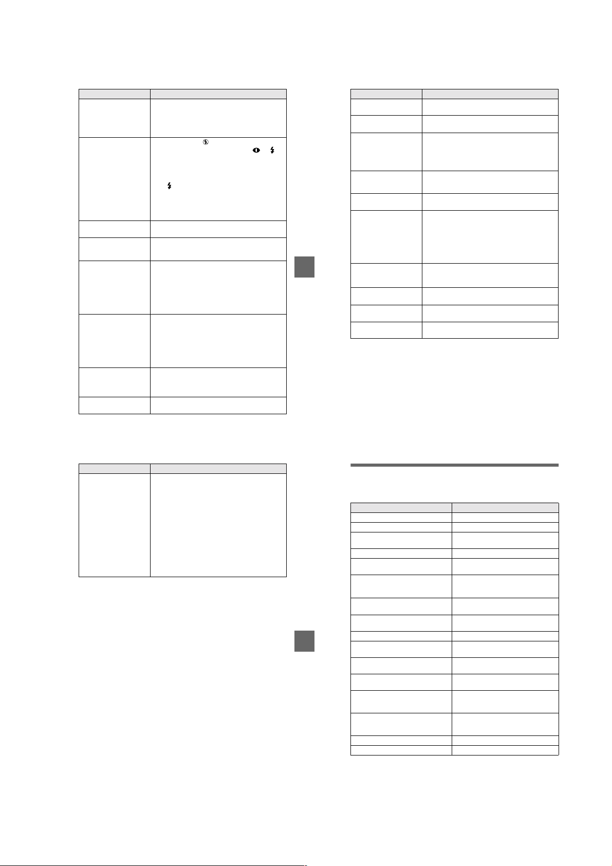
Symptom Cause and/or Solution
The picture is too dark.•You are shooting a subject with a light source
The flash does not work. •The flash is set to .
The date and time are
recorded incorrectly.
Vertical streaks appear
when you are shooting a
very bright subject.
The battery life is short.•You are recording/playing back images under
The battery remaining
indicator is incorrect.
Sufficient battery
remaining indicator is
displayed but the power
runs out soon.
The zoom does not work. •PROGRAM AE is set to the Panfocus mode.
behind the subject.
t Adjust the expo sure (page 43).
t Adjust the brightn es s of the LCD screen (page
36).
t Set the flash to au to (no indicator), or
(page 19).
•
PROGRAM AE is set to the Twilight, Twilight
plus, or Landscape mode.
t Cancel the mode (page 41) or set the flash to
.
•
The MODE selector is set to MOVIE.
t Set it to STILL.
•
The flash is not popped up.
t Pop up the flash (page 19).
•
The date and time are not set correctly.
t Set the correct date and time (page 13).
•
The smear phenomenon is happening.
t This is not a malfunction.
extremely cold temperatures.
•
The battery pack is not charged enou gh.
t Charge the battery pack fully.
•
The battery pack is dead.
t Replace the battery pack with a new one (page
11).
•
You have used the camera for a long time in an
extremely hot or an extremely cold location.
•
The battery pack is dead.
t Replace the battery pack with a new one (page
11).
•
The battery pack is discharged.
t Install a charged batter y pack (pages 9, 11).
t Fully charge the battery pack (page 9).
t Cancel the Panfocus mode (page 41).
Symptom Cause and/or Solution
Digital zoom does not
function.
Your camera cannot pla y
back images.
The image and sound are
interfered by noise when
you play back an image on
a personal computer.
The image cannot be
played back on a personal
computer.
Y our camera cannot delete
an image.
The power turns off
suddenly.
The image does not
Additional information
appear on the TV screen.
A file error occurs when
you play back a file.
The PROGRAM AE
function does not work.
The LCD screen freezes
momentarily.
•
You cannot use digital zoom to record moving
pictures.
•
The MODE selector is set to STILL or MOVIE.
t Set it to PLAY (pages 22, 23).
•
You are playing back th e file di rectly from the
“Memory Stick.”
t Copy the file to the hard disk o f t he personal
computer and then play ba ck the file from the
hard disk (page 28).
t Consult the person al computer or software
manufacturer.
•
The image is protected.
t Cancel the protection (page50).
•
With the MODE selector set to STILL or MOVIE,
if you do not operate the camera for about three
minutes while the power is o n, the camera turns off
automatically to prevent wearing down the battery.
t Turn on the camera.
•
The battery is discharged.
t Replace it with a charged battery.
•
The video output signal se tti ng of your camera is
incorrect.
t Change the setting (page 36).
•
The image size is larger than 2240×1680.
t Use an image size of 2240×1680 or smaller.
•
The camera is set to text mode.
t Cancel text mode (p age 39).
•
This is a characteristic of th e s ystem and is not a
malfunction.
Symptom Cause and/or Solution
Your personal computer
does not recognize your
camera.
•
The camera is turned off.
t Turn on the camera.
•
The battery level is low.
t Use the AC power adaptor/charger (page 12).
•
The USB cable is not connected firmly.
t Disconnect the USB cable, and connect it again
firmly . Mak e sure that “PC MODE” is di splayed
on the LCD screen (page 26 ).
•
The USB connectors on your personal computer are
connected to other equipment besides the keyboard,
the mouse, and your camera.
t Disconnect the USB cables except for the ones
connected to the keyboard, the mouse, and your
camera (page 25).
59
60
Warning and notice messages
Various messages appear on the LCD screen. Check the corresponding descriptions
in the following list.
Message Meaning
NO MEMORY STICK No “Memory Stick” has been inserted.
SYSTEM ERROR Turn the power off and on again.
MEMORY STICK ERROR The inserted “Memory Stick” cannot be
FORMAT ERROR Failed to format the “Memory Stick.”
MEMORY STICK LOCKED The write-protect tab on the “Memory
NO MEMORY SPACE The capacity of the “Memory Stick” is
NO FILE No image has been recorded on the
FILE ERROR An error occurred while playing back the
FILE PROTECT The im age is protected against erasure.
Additional information
for “InfoLITHIUM” battery only The battery is not the “InfoLITHIUM”
NOT ENOUGH MEMORY The images you want to copy are too big
DIRECTORY ERROR A directory with the same name already
IMAGE SIZE OVER You are playing back an image of a size
INVALID OPERATION You are playing back a file that was
E
-
used with your camera, or is damaged.
Stick” is set to the LOCK position.
full, and you cannot record or copy
images.
“Memory Stick.”
image.
type.
to copy with your camera.
exists.
that cannot be played back with your
camera.
created on equipment other than your
camera.
The battery level is low or zero.
The image is protected.
61
62
1-15
Page 22
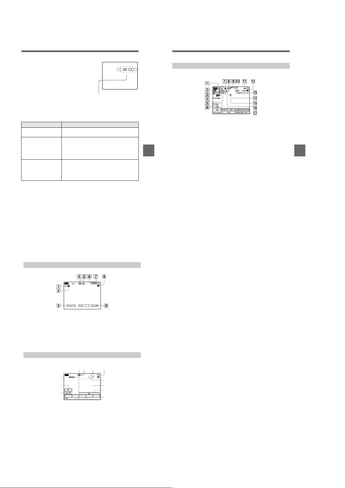
Self-diagnosis display
Your camera has a self-diagnosis display. This
function displays the camera condition on the
LCD screen with a comb i nation of a letter and
four digits of numbers. If this occurs, check the
following code chart. The code informs you of the
camera’s curr ent condition. The last two digits
(indicated by ss) will differ de pending on the
state of the camera.
Self-diagnosis display
•
C:ss:
ss
You can reverse the camera
malfunction yourself.
•
E:ss:
ss
Contact your Sony dealer or local
authorized Sony service facility.
First three digits Cause and/or Corrective Action
C:32:
ss
C:13:
ss
E:61:
ss
E:91:
ss
If you are unable to solve the problem even after trying the corrective
actions a few times, contact your Sony dealer or local authorized Sony
service facility.
•
There is trouble with you r camera’s hardware.
t Turn the power off and on again.
•
An unformatted “Memory Stick” is inse rted.
t Format the “Memory Stick” (page 33).
•
The inserted “Memory Stick” cannot be used with
your camera, or is damaged.
t Insert a new “Memory Stick” (page 15).
•
A camera malfunction that you cannot reverse has
occurred.
t Contact your Sony dealer or loc al authorized
Sony service facility and inform them of the 5digit service code. (example: E:61:10)
LCD screen indicators
The indicators during recording
1856
A Battery remaining indicator
B PROGRAM AE/flash mode/
flash level indicator
C White balance/EV level/
sharpness indicator
D Picture effect indicator
Additional information
E Date/time indicator
F Aperture/shutter speed
indicator
G AE lock/focus lock indicator
H Recording mode indicator
I Image size indicator
J Self-diagnosis function/
recording time indicator
K Number of recorded images
L Remaining memory capacity
indicator
M Moving image/VOICE recording
time indicator
N Self-timer indicator
O Spot light-metering indicator
P Focus/macro mode indicator
Q Menu bar and guide menu
They appear by pressing
control button and disappear by
pressing V of it.
v
on the
Additional information
When playing back still images
60
A Protect indicator
B Print mark indicator
C File name
D Recording mode indicator
E Image size indicator
F Image num be r
When playing back moving images
45 6
60
min
VOL.
1
2
3
INDEX
SELECT OK
A VOL. (Volume) indicator
B Playback/pause buttons
: during pause
B
: during playback
X
C Fast-forward/rewind buttons
D Recording mode indicator
E Image size indicator
66
G Number of stored images in
“Memory Stick”
H Remaining memory capacity
indicator
I Recording date of the playback
image/menu bar and guide
menu
7
6/8
320
0:12
8
9
0
SETUPTOOLDELETE
FILE
qa
MENU BAR OFF
F Image number/number of
stored images in “Memory
Stick”
G Remaining memory capacity
indicator
H Counter
I Playback image
J Play bar
K Menu bar an d guide menu
63
65
1-16 E
1-16
Page 23
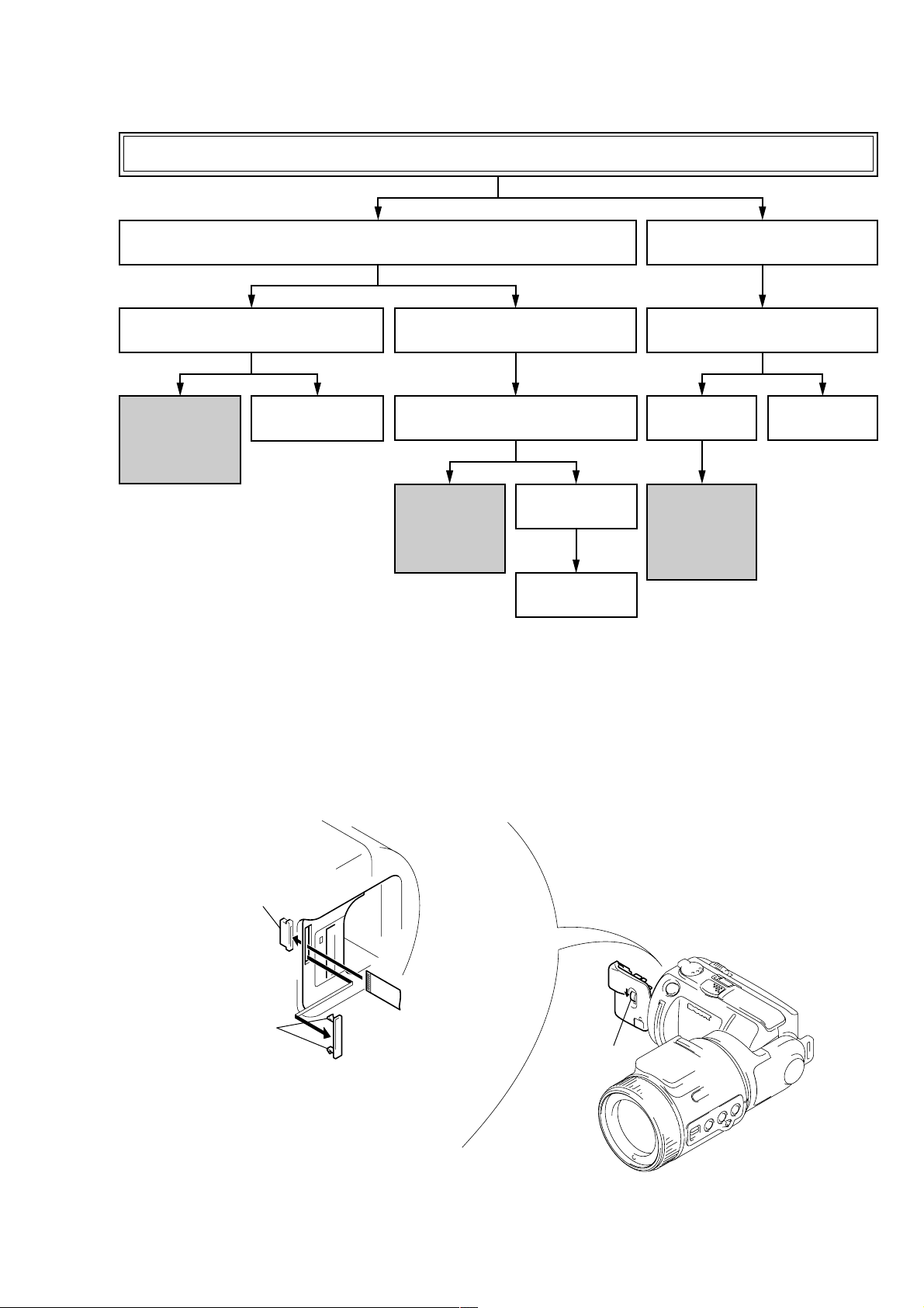
• This set can be disassembled in the order shown below.
DSC-F505V
SECTION 2
DISASSEMBLY
DSC-F505V
2-5. LCD PANEL BLOCK
CONTROL SWITCH BLOCK (FK)
(Page 2-4)
SERVICE POSITION-2
· LCD PANEL BLOCK
· CONTROL SWITCH
BLOCK (FK)
(Page 2-4)
2-1. REAR CABINET BLOCK
(Page 2-2)
2-11. CRYSTAL INDICATION
MODULE
(Page 2-8)
2-6. HI-73, DD-148 BOARDS,
BATTERY HOLDER BLOCK
(Page 2-5)
2-7. UPPER CABINET BLOCK
FLASH UNIT (MC)
(Page 2-5)
SERVICE POSITION-3
· HI-73 BOARD
· DD-148 BOARD
(Page 2-6)
2-8. FRONT CABINET
ASSEMBLY
(Page 2-6)
FP-37 FLEXIBLE BOARD
(Refer to 2-9. and 2-10.)
(Page 2-7)
2-2. ZOOM LENS BLOCK
(Page 2-2)
2-3. CABINET (LT) BLOCK
(Page 2-3)
2-4. LENS BLOCK
(Page 2-3)
SERVICE POSITION-1
(LENS, BLOCK AREA)
· CD-283 BOARD
· PS-434 BOARD
· SY-62 BOARD
(Page 2-3)
2-12. FLASH UNIT (ST)
(Page 2-8)
• ATTACHMENT OF CPC-9 JIG
Control switch block (FK)
(CN002)
Two claws
Note 1: Don't use the 12 pin flexible board of CPC-9 jig.
It causes damage to the unit.
Note 2: The old CPC-9 jig (Parts code: J-6082-393-B)
cannot be used, because it cannot operate
the adjustment remote commander.
1
18
CPC cover
CPC-9 jig (J-6082-393-C)
(18p flexible board)
Slide the Release knob in the direction of arrow A.
To open the Battery lid.
A
Release knob
2-1
Page 24
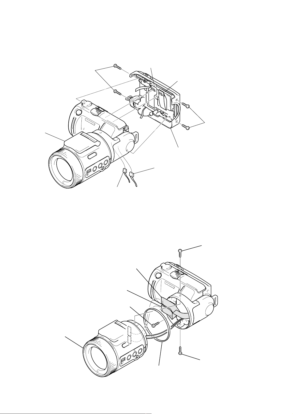
Note: Follow the disassembly procedure in the numerical order given.
2-1. REAR CABINET BLOCK
Front cabinet assembly
2 Two screws
(M1.7)
4 FP-134 flexible board
(CN901)
5 Flexible board (Control switch block (FK))
(CN705)
1 Two screws
(M1.7)
3 Rear cabinet assembly
6 Harness (HB-50)
(CN706)
7 Harness (speaker)
(CN252)
2-2. ZOOM LENS BLOCK
6 Zoom lens block
1 Screw (M1.7)
4 FP-37 flexible board
(CN802)
5 FP-37 flexible board
(CN801)
3 Screw (M1.7)
2 Screw (M1.7)
7 MF ornament
2-2
Page 25
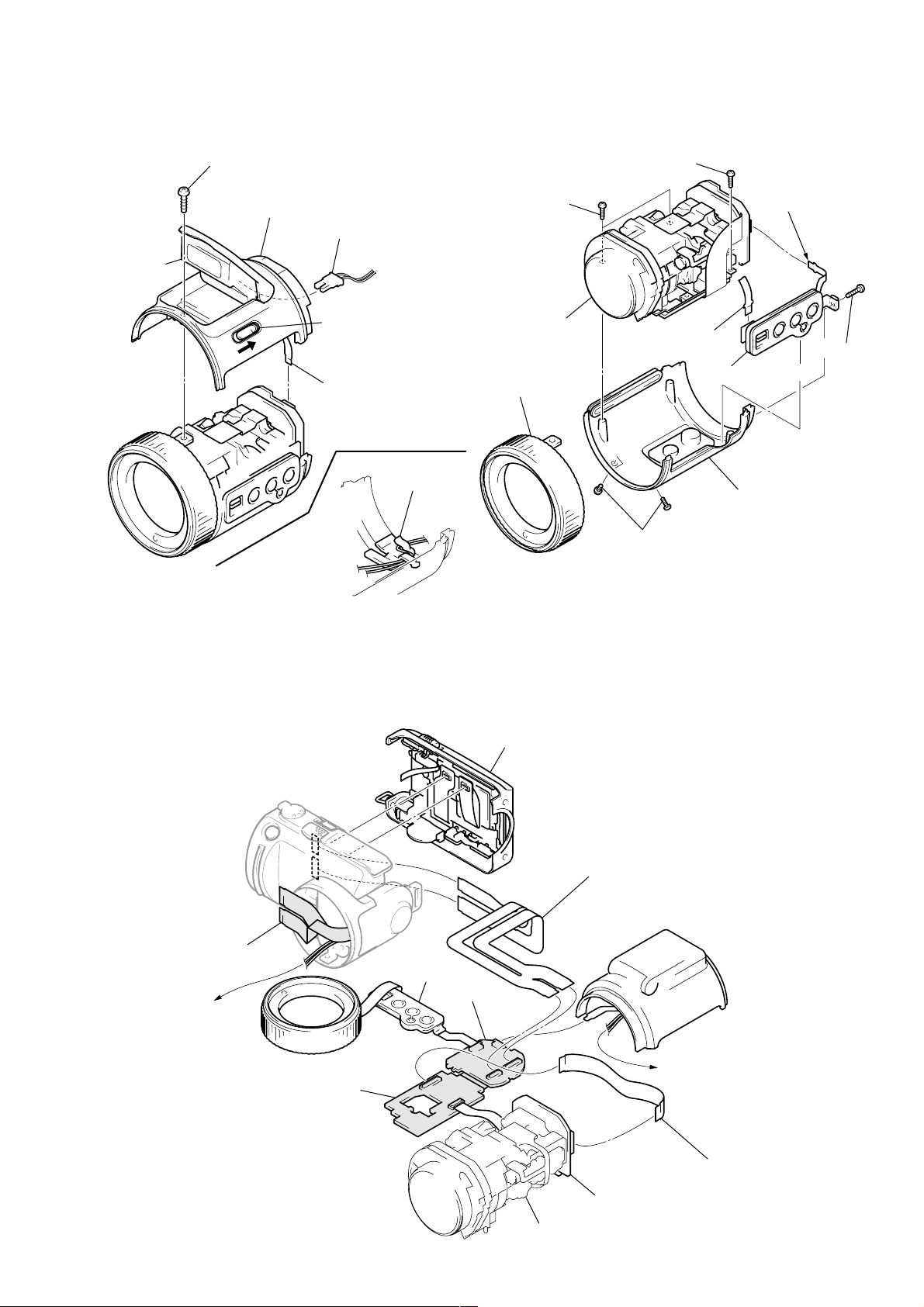
2-3. CABINET (LT) BLOCK 2-4. LENS BLOCK
Flash unit
(Note)
2 Screw (M1.7)
3 Cabinet (LT) block
7 Two screws
(M1.7)
5 Harness (MS-114)
(Flash unit (ST), 2P)
(Note)
8 Screw (M1.7)
2 Flexible board
(CN803)
1 Push the Release knob
4 FP-136 flexible board
(CN804)
Harness clamp
Cabinet (LT) block
(Bottom view)
Note: Clamp the cables after attaching the Harness
(MS-114). If clamped with the flash unit closed,
the flash unit cannot be opened. Be sure to
clamp the cable with the flash unit opened.
0 Lens block
6 Cabinet (MF)
assembly
3 Flexible board
(CN001)
4 Control switch
block (CF)
9 Cabinet (LB)
assembly
5 Two screws
(M1.7)
[SERVICE POSITION-1 (LENS BLOCK AREA: CD-283, PS-434, SY-62 BOARDS)]
Rear cabinet block
1 Screw (M1.7)
FP-37 flexible board
(Not used)
Harness (MS-114)
(to Cabinet (LT) block)
Cabinet (MF) assembly
Control switch block (CF)
PS-434 board
SY-62 board
2-3
Lens block
Extension cable (39, 39P 0.3 mm)
Parts No. : 1-678-657-11
(HI-73 board: CN701, 702)
(SY-62 board: CN801, 802)
Cabinet (LT) block
(Flash unit (ST))
Harness (MS-114)
(from Front cabinet block)
Extension cable (39P 0.3 mm)
Parts No. : J-6082-448-A
CD-283 board
(PS-434 board: CN602)
(CD-283 board: CN101)
Page 26
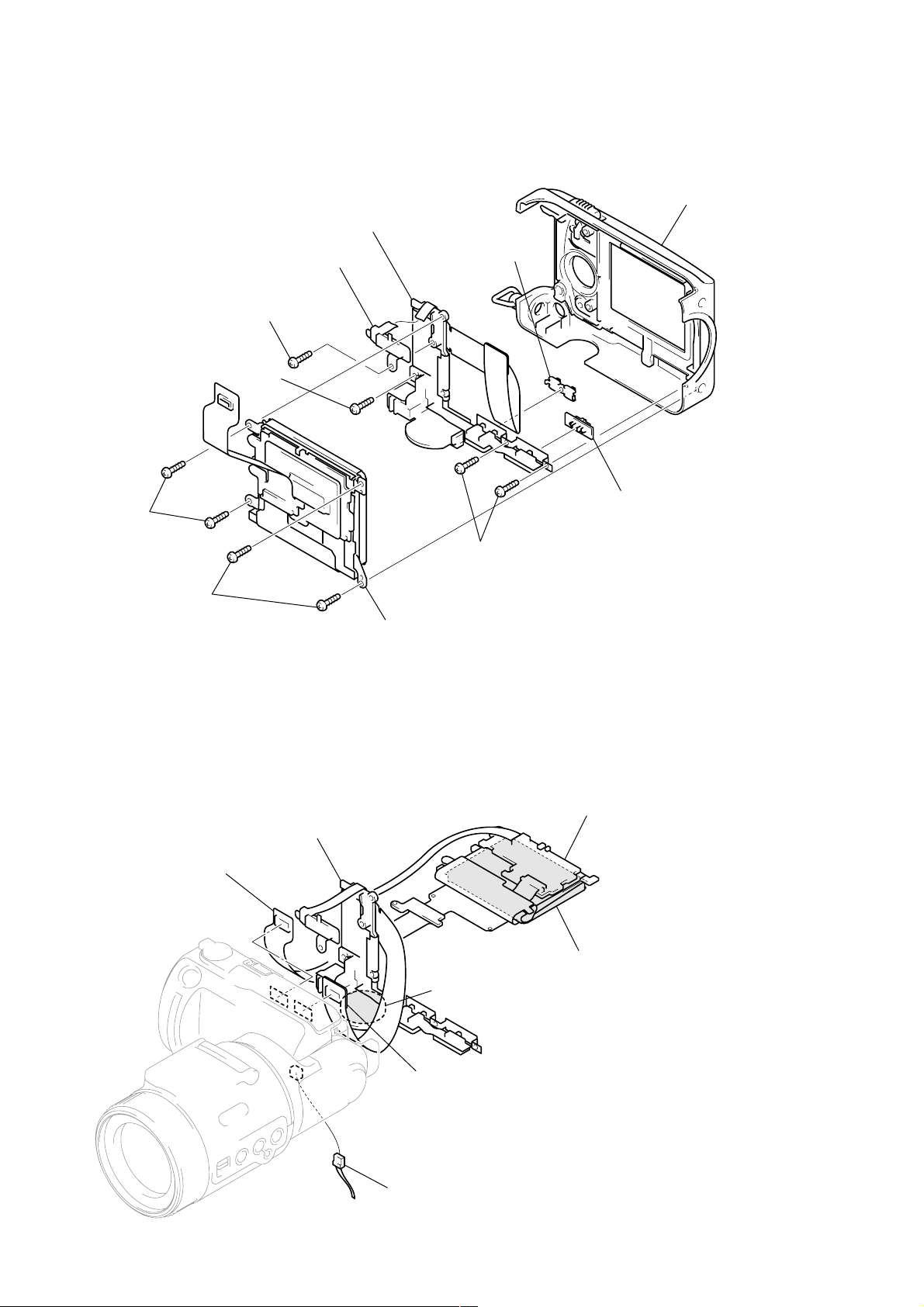
2-5. LCD PANEL BLOCK, CONTROL SWITCH BLOCK (FK)
8 Control switch block (FK)
Rear cabinet assembly
3 Two screws
(1.7 × 4)
4 Two screws (1.7)
2 Zoom switch
(RV001)
1 Screw (1.7 × 4)
6 Screw (M1.7)
9 Button (LCD bright)
0 Knob (LCD back light)
7 Two screws (M1.7)
5 LCD panel block
(Refer to 2-11. Crystal indication module)
[SERVICE POSITION-2 (REAR CABINET AREA: LCD PANEL BLOCK, CONTROL SWITCH
BLOCK (FK))]
Cold cathode fluorescent tube (ND901)
(with Inverter transformer unit)
Control switch block (FK)
FP-134 flexible board
(CN901)
Crystal indication module (LCD901)
SP901
Flexible board (control switch block (FK))
(CN705)
(with FP-134 flexible board)
Harness (speaker)
(CN252)
2-4
Page 27
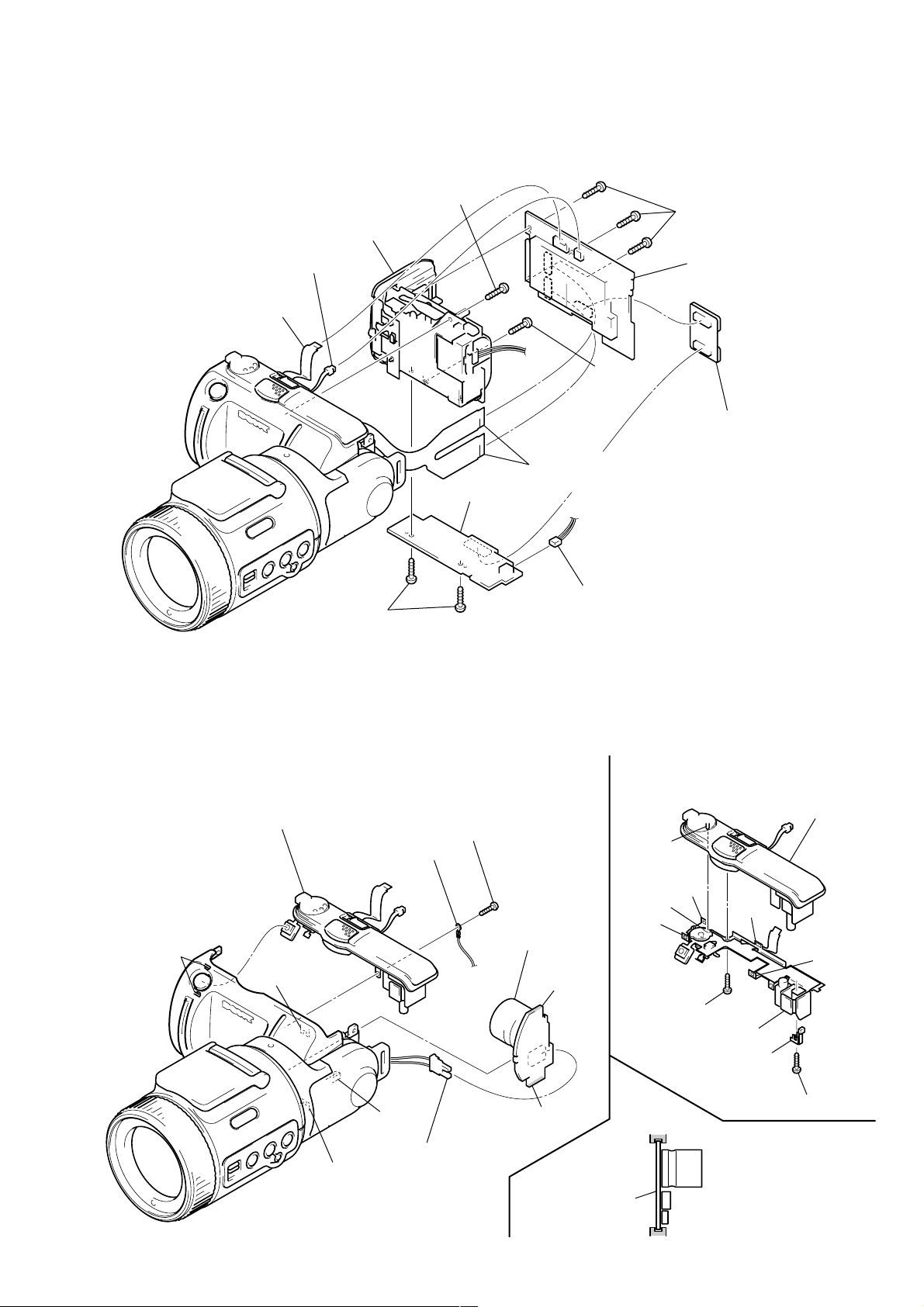
2-6. HI-73, DD-148 BOARDS, BATTERY HOLDER BLOCK
1 FP-132 flexible board
(HI-73 board: CN707)
(DD-148 board: CN003)
5 Three screws
(1.7 × 4)
qa Two screws
(1.7 × 4)
8 Screw (M1.7)
0 Battery holder block
9 Screw
(M1.7)
qs DD-148 board
6 HI-73 board
2 FP-37 flexible board
(CN701, 702)
3 Harness (microphone)
(CN251)
7 Harness (MD-97)
(CN002)
4 Control switch block (PW)
(CN704)
2-7. UPPER CABINET BLOCK, FLASH UNIT (MC)
Note: When the flash unit (MC) charging failed, Page: D, Address: 67, Data: 04 are written.
After repair, be sure to write Page: D, Address: C7, Data: 00.
3 Two claws
4 Upper cabinet block
Groove
2 Harness (GN-52)
6 Claw
5 Harness (MS-114)
Groove
1 Screw (M1.7)
7 Flash unit (MC) (Note)
Edge
Edge
Flash unit (MC)
Details diagram on removal and attachment
of Control switch block (PW)
Upper cabinet block
Pin
Claw
Hole
Claw
Screw (1.7 × 4)
Control switch block (PW)
JK retainer assembly
Groove
Claw
Claw
Screw (1.7 × 4)
Note for installation of
Flash unit (MC)
Should be fit to the Front
cabinet groove.
2-5
Groove
Page 28
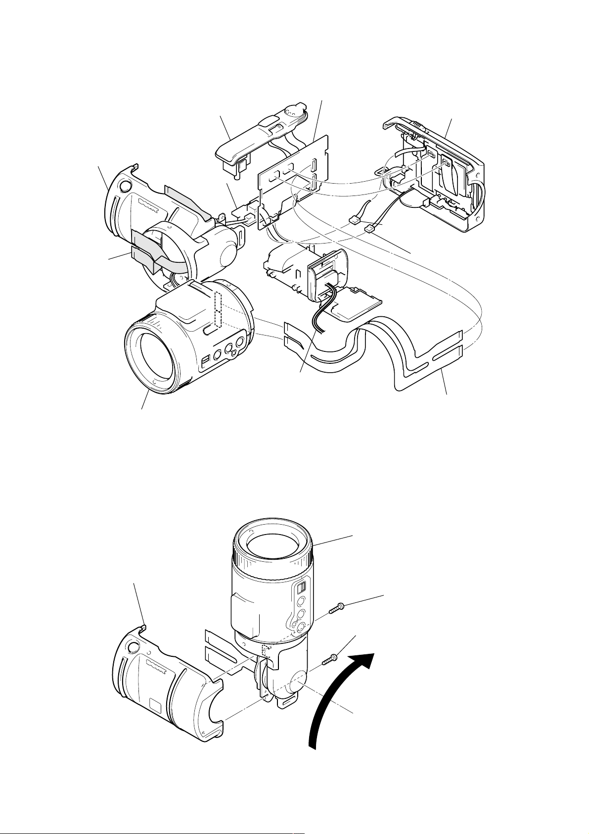
[SERVICE POSITION-3 (HI-73, DD-148 BOARDS)]
Control switch block (PW)
Front cabinet block
DD-148 board
FP-37 flexible board
(Not used)
HI-73 board
Rear cabinet block
Harness (HB-50)
(CN706)
Harness (speaker)
(CN252)
Zoom lens block
2-8. FRONT CABINET ASSEMBLY
4 Front cabinet assembly
Battery holder block
(to AC power adaptor)
Extension cable (39, 39P 0.3 mm)
Parts No. : 1-678-657-11
(HI-73 board: CN701, 702)
(SY-62 board: CN801, 802)
1 Lift up the Zoom lens block.
3 Screw (M2 × 4)
2 Screw (M2 × 4)
2-6
Page 29
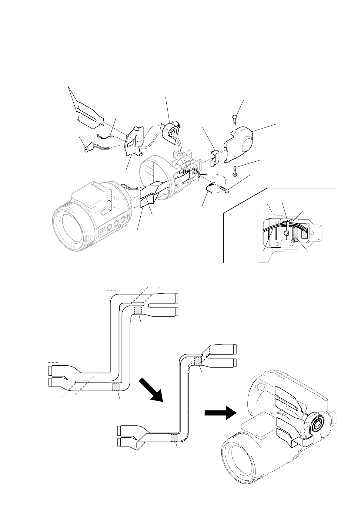
2-9. REMOVAL AND ATTACHMENT OF FP-37 FLEXIBLE BOARD
Note: For folding new FP-37 flexible board, refer to “2-10. To fold the
new FP-37 flexible board” .
FP-37 flexible board
Harness (MS-114)
Harness (GN-52)
FP holder
FP-37 flexible board
(CN801)
When attaching, coil in the direction of
arrow A with two and a half revolutions.
(FP-37 flexible board )
A
Hook cover
Harness (GN-52)
FP-37 flexible board
(CN802)
Screw (M1.7)
Screw (M1.7)
Screw (M2 x 4)
Hook the claw of harness
Harness (MS-114)
Hinge cover
Harness (GN-52)
FP guard
2-10. TO FOLD THE NEW FP-37 FLEXIBLE BOARD
: Fold
Adhesive tape
: Fold
Adhesive tape
1-678-657-xx
FP-37
Adhesive tape
1-678-657-xx
FP-37
Adhesive tape
Note: For attaching new FP-37 flexible board, refer
to “2-9. Removal and attachment of FP-37
flexible board” .
2-7
Page 30
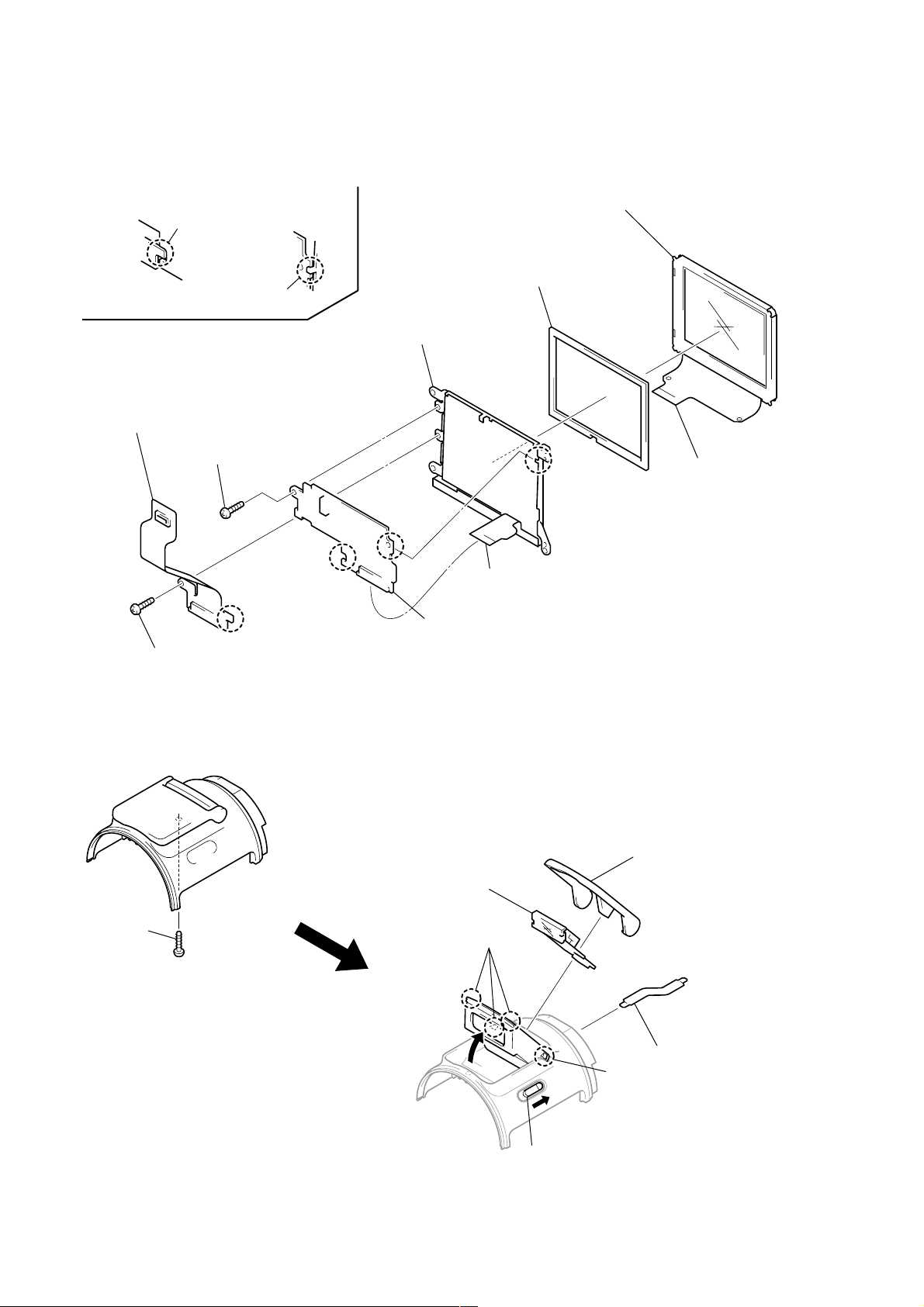
2-11. CRYSTAL INDICATION MODULE
Note for installation
Portion A and B
Portion C and D
8 Cold cathode fluorescent tube (ND901)
5 FP-134 flexible board
7 Screw (M1.7)
A
B
2 Crystal indication module (LCD901)
3 BL cushion
D
C
6 Flexible board
(Inverter transformer unit)
9 Inverter transformer unit
1 Flexible board
(FP-134 board)
4 Screw (M1.7)
2-12. FLASH UNIT (ST)
1 Screw
(M1.7 × 4)
7 Flash unit (ST)
5 Three claws
6 Cabinet (ST)
2 FP-136 flexible board
(Flash unit ST)
4 Claw
2-8
3 Push the Release knob
Page 31

2-13. CIRCUIT BOARDS LOCATION
FLASH UNIT (MC)
FLASH UNIT (ST)
DD-148
(DC/DC CONVERTER)
INVER TER TRANSFORMER UNIT
PS-434
(CAMERA DISPLAY, MEMORY, AUDIO AD/DA CONVERTER, LENS DRIVE)
CN-121
(CONNECTION)
HI-73
(LCD DRIVE, TIMING GENERATOR, VIDEO, USB I/F, AUDIO, HI CONTROL)
CD-283
(CCD IMAGER, CAMERA)
SY-62
(SH DSP, MEMORY)
2-14. FLEXIBLE BOARDS LOCATION
CONTROL SWITCH BLOCK (FK)
FP-136
CONTROL SWITCH BLOCK (PW)
FP-132
FP-36
CONTROL SWITCH BLOCK (CF)
MANUAL FOCUS BLOCK
2-9
E
FP-134
FP-37
LENS BLOCK
Page 32

3-1. OVERALL BLOCK DIAGRAM
DSC-F505V
SECTION 3
BLOCK DIAGRAMS
LENS
M902
FOCUS
MOTOR
(SEE PAGE 4-19)
FOCUS
MOTOR
DRIVE
MANUAL FOCUS BLOCK
(SEE PAGE 4-51)
BRIGHT
LEVEL
SENSOR
FLASH UNIT (ST)
FLASH
CONTROL
DC 300V
M901
ZOOM
MOTOR
FOCUS
SENSOR
IC402
ZOOM
MOTOR
DRIVE
PE EN0, PE DIR0A, PE DIR0B
MANUAL FOCUS
SWITCH
PHOTOTR OUT
(SEE PAGE 4-51)
STRB ON
FLASH UNIT (MC)
(SEE PAGE 4-52)
BT901
BATTERY
TERMINAL
ND FILTER
MOTOR
MM
ZOOM
SENSOR
CONTROL SWITCH BLOCK (CF)
(SEE PAGE 4-51)
FOCUS A, B KEY AD4
FLASH
CHARGE
+
S
–
FILTER
ND
M M
HALL
H
HALL (+) HALL AD
PE EN1, PE DIR1A, PE DIR1B
ST UNREG
STB CHARGE
XSTB FULL
BATT UNREG
BATT SIG
BATT GND
05
IRIS
METER
DRIVE (–)
(SEE PAGE 4-19)
IRIS DRIVE
HALL AMP
FUNCTION
SWITCH
OPEN (FLASH)
SWITCH
DD-148 BOARD
CD-283 BOARD PS-434 BOARD
(SEE PAGE 4-19)
IC404
IC405
IC101
CCD
IMAGER
(SEE PAGE 4-9)
V1A, V1B, V2,
V3A, V3B, V4, VSHT
IC403
IRIS
DRIVE
IRIS CONT 1, 2
XSTB OPEN
V OUT
H1, H2
CONVERTER
(SEE PAGE 4-20)
STRB ON
IC001
DC/DC
CONVERTER
(SEE PAGE 4-45)
SH, AGC, A/D
CONVERTER
(SEE PAGE 4-9)
GENERATOR
(SEE PAGE 4-9)
ND FILTER
(SEE PAGE 4-19)
MSHUT ONDRIVE (+)
IC406
EVR
D/A
Z SENS RST
F SENS RST
IC103
IC102
TIMING
IC401
DRIVE
CAM SO, XCAM SCK
PE DAC LEVEL 1, 2
CNT Y, CNT C
SP VOL
DATA BUS 12
ND ONND DRIVE (–)
EVER 3.5V
PANEL +13.5V
PANEL +4.9V
PANEL +6.5V
A +4.9V
M +5V
PANEL –15V
CAM –7.5V
D 3.2V
CAM +15V
D 1.8V
A 3.2V
SYS DD ON
LCD DD ON
CAM DD ON
HI UNREG
BL UNREG
IC301
CAMERA DSP,
MEMORY CONTROL,
VIDEO DECODER,
CAM SO, XCAM SCK
OPD, OSD,
HOST IF,
RES CONTROL,
SG, JPEG,
L-MODE
(SEE PAGE 4-16)
EVER 3.5V
16
12 20
Y OUT
C OUT
AU SDTI
AU SDTO
PANEL Y
PANEL R-Y
PANEL B-Y
EXT STRB ON
PHOTOTR OUT
STRB ON
HI UNREG
IC407
3.1V
REGULATOR
(SEE PAGE 4-41)
ADDRESS BUS 1414
DATA BUS 1616
CN-121
BOARD
(SEE PAGE 4-17)
IC252
AUDIO
AD/DA
CONVERTER
(SEE PAGE 4-17)
IC408
RESET
(SEE PAGE 4-41)
IC402
RESET
(SEE PAGE 4-41)
IC405
TIMER
CLOCK
(SEE PAGE 4-42)
+
–
IC504
16M FLASH ROM
(SEE PAGE 4-25)
16 16 14
20
DATA BUS
ADDRESS BUS
(SEE PAGE 4-24)
IC303
IC304
64M
SDRAM
A OUT L
REC OUT
BACK UP VCC XPWER SW
SYS DD ON
LCD DD ON
CAM DD ON
BATT SIG
STB CHARGE
XSTB FULL
RTS SIO,
RTS SCK
BT001
LITHIUM
BATTERY
CAM SI, CAM SO, XCAM SCK
IC404
HI CONTROL
(SEE PAGE 4-42)
IC506
64M SDRAM
(SEE PAGE 4-25)
IC507
EEPROM
HALL AD
FOCUS A
FOCUS B
KEY AD4
XSTB OPEN
HI SO, HI SI, XHI SCK
XSHTR LOCK SW
XSHTR SW
MOVIE/XSTILL SW
XCAM/PB SW
BL ON
KEY AD1
KEY AD2
ZOOM SW AD
16
(SEE PAGE 4-23)
HI SO, XHI SCK
LANC OUT
LANC IN
SY-62 BOARD
IC501
MC CAM,
SH DSP
MS DIO, MS BS, MS SCLK
USB DATA
HI SO, HI SI, XHI SCK
IC801
I/O EXP
(EVR)
(SEE PAGE 4-31)
IC406
EEPROM
(SEE PAGE 4-42)
IC401
LANC
(SEE PAGE 4-41)
HI-73 BOARD
IC601
USB I/F
(SEE PAGE 4-40)
V OUT ON
Y OUT
C OUT
CNT Y, CNT C
SP VOL
A OUT L
REC OUT
PANEL Y
PANEL R-Y
PANEL B-Y
LANC SIG
LANC DC
D+
D–
IC651
VIDEO
AMP
(SEE PAGE 4-36)
IC253
AUDIO
AMP
(SEE PAGE 4-37)
IC803
LCD
DRIVE
(SEE PAGE 4-32)
BL ON
EXT STRB ON
VR
VG
VB
BL UNREG
KEY AD1
KEY AD2
ZOOM SW AD
CN703
MEMORY
STICK
CONTROL SWITCH
BLOCK (PW)
(SEE PAGE 4-52)
XPWER SW
XSHTR LOCK SW
XSHTR SW
MOVIE/XSTILL SW
XCAM/PB SW
SP OUT+, SP OUT–
MIC SIG
IC901
LCD
TIMING
GENERATOR
(SEE PAGE 4-33)
CONTROL
SWITCH
BLOCK (FK)
(SEE PAGE 4-49, 50)
D+
D–
V OUT
AU OUT
POWER
SWITCH
SHUTTER
SWITCH
MOVIE/STILL
/PLAY
SWITCH
INVERTER
TRANSFORMER
UNIT
FUNCTION
KEY
ZOOM
SWITCH
CN002
DIGITAL
I/O
J001
A/V OUT
(MONO)
SP901
SPEAKER
MICROPHONE
LCD901
COLOR
LCD
UNIT
ND901
BACK LIGHT
VH
VL
J9001
(EXT FLASH)
MIC901
3-1 3-2
Page 33

DSC-F505V
3-8. POWER BLOCK DIAGRAM 1
BT901
BATTERY
TERMINAL
+
s
–
DD-148 BOARD FLASH UNIT (MC)
CN002 CN001
CN001
BATT UNREG
1
BATT SIG
2
BATT GND
3
F001
F002
F003
F004
4
1
Q011
SWITCHING
495 kHz
IC001 1
ST UNREG ST UNREG
STRB CHARGE
XSTRB FULL
T003
5
7
8 54
2 51
3
1.2 Vp-p
D006
RECT
D001
RECT
SYS DD ON
CAM DD ON
LCD DD ON
2 2
3
4
V+
V-
VCC = UN+1.6V
VG = 6V
STRB CHARGE
3
XSTRB FULL
4
DC/DC CONVERTER
(SEE PAGE 4-41)
VCC (0) 1 – 2
53
VCC (0) 3, 4
58
VCC (0) 5, 6, 7
64
VSS (0) 1– 2
VSS (0) 4, 5, 6
59
VCC
26
VG (0) 1
+IN (E) 7
8
-IN (E) 7 – 2
7
OUT7
1
RT
33
CT
34
CTL1 – 4 7
27
CTL5
28
CTL6
29
IC001
L001
-IN (C) 6
OUT6
-IN (A) 6
-IN (E) 6
OUT5
-IN (C) 5
-IN (E) 5
-IN (C) 8
OUT4
-IN (E) 4
OUT3
-IN (E) 3
OUT2 – 1
OUT2 – 2
-IN (E) 2
OUT1 – 1
OUT1 – 3
OUT1 – 4
-IN (E) 1
(SEE PAGE 4-52)
Q001, 002
14
63
10
12
62
17
18
23
61
21
60
36
55
57
39
52
49
48
44
Q014
Q003
TRANS
DRIVE
Q009
SWITCHING
Q010
SWITCHING
L004
Q003, 005, 006
DRIVE
L005
Q004, 007, 008
DRIVE
Q012
SWITCHING
4
F
3
2
P
1
1
4
4
3
2
1
EMERGENCY
Q013
SWITCHING
T001
T001
T002
Q025
DETECT
SWITCHING
L002
6
S
5
Q022
Q019
SWITCHING
D002
8
D005
RECT
7
2
3
5
5
6
7
8
Q021
SWITCHING
SWITCHING
L003
Q020
D003
D007
RECT
SWITCHING
Q006
Q015
DC 300V
+
CN002
C009
Q023 (1/2)
Q024 (1/2)
D004
RECT
1 2
CN003
DC 300V
FLASH UNIT (ST)
(SEE PAGE 4-51)
L016
L013
L012
L009
Q023 (2/2)
Q024 (2/2)
Q016, Q017
L001
L014
4
Q030, Q31
LX
CN004
A 4.9V
Q032, 033
L010
L015
L011
L006
L007
L008
IC002
DC/DC
CONVERTER
(SEE PAGE 4-46)
D002
5
6
V OUT
CE
A
XSTRB FULL
STRB CHARGE
BL UNREG
HI UNREG
PANEL +13.5V
PANEL +6.5V
PANEL -15V
PANEL +4.9V
CAM +15V
CAM -7.5V
A +4.9V
2
3
EVER 3.5V
TO SY-62
BOARD
(CN804)
(SEE PAGE 3-18)
CN003
7
9
3
4
6
10
14
21
12
25
23
15
16
20
M +5V
22
27
D 1.8V
ı
30
A 3.2V
31
32
D 3.2V
24
26
8
TO
HI-73
B
BOARD
(CN 707)
(SEE PAGE 3-17)
BATT SIG
BAT SIG
05
SYS DO ON
CAM DD ON
LCD DD ON
SYS DD ON
LCD DD ON
CAM DD ON
5
11
13
19
3-15 3-16
Page 34

3-9. POWER BLOCK DIAGRAM 2
HI-73 BOARD SY-62 BOARD CN-121 BOARD
CN707 CN702
CAM -7.5V
23
CAM +15V
25
27
D 1.8V
ı
30
M +5V
20
22
A +4.9V
15
16
A 3.2V
31
32
D 3.2V
24
26
TO DD-148
BOARD
(CN003)
(SEE PAGE 3-16)
B
PANEL +6.5V
14
PANEL +4.9V
12
PANEL +13.5V
10
PANEL -15V
21
FB601
L802
L903
L901
L902
L255 L252
Q253
L254
L801
IC601
UBS I/F
SEE PAGE
4-40
L651 L652
IC253
AUDIO
(EVR)
SEE PAGE
4-37
IC801
I/O EXP
(EVR)
SEE PAGE
4-31
IC803
LCD
DRIVE
SEE PAGE
4-32
Q651, 652
TIMING
GENERATOR
SEE PAGE
D701
(ACCESS)
IC901
LCD
4-33
IC651
VIDEO
AMP
SEE PAGE
4-36
Q702, 703
IC902
VCO,
COM AMP
SEE PAGE
4-33
CAM -7.5V
CAM 15V
MS POWER ON MS POWER ON
38
37
28
D 1.8V
ı
30
M 5V
35
36
A 4.9V
33
34
A 3.2V
31
32
D 3.2V
26
27
CN701
33 7
CN703
VCC
3
9
CN901
VSH
16
25
VGH
23
VSS
22
LCD901
COLOR
MEMORY
STICK
LCD
UNIT
CAM -7.5V
2
CAM 15V
3
10
D 1.8V
ı
12
M 5V
4
5
A 4.9V
6
7
A 3.2V
8
9
D 3.2V
13
14
L501 L502
CN801
L506
16
LED901
ND901
BACK LIGHT
IC501
MC CAM
SH DSP
SEE PAGE
4-23
D29/PTB5
D21/PTA5
DSC-F505V
CN805 CN002 CN001CN802
CAM -7.5V
CAM 15V
IC503
INVERTER
SEE PAGE
4-24
IC507
EEPROM
SEE PAGE
4-24
26
L505
L504
D 3.2V
Q801, 802
FB503
FB501
IC504
16M FLASH
ROM
SEE PAGE
4-25
IC506
64M SDRAM
SEE PAGE
4-25
CN803
2
10
4
DAC ENB
STRB PHOTO ON
2
10
4
4
3
13
D 1.8V
ı
14
M 5V
5
6
A 4.9V
7
8
A 3.2V
9
10
D 3.2V
11
12
99
80
CN002
D 3.2V
D 3.2V
PHOTOTR 5V
CONTROL SWITCH
BLOCK (CF)
(SEE PAGE 4-51)
FUNCTION
SW
CAM -7.5V
4
CAM 15V
3
13
ı
14
5
6
7
8
9
10
11
12
99
80
D 1.8V
M 5V
A 4.9V
A 3.2V
D 3.2V
DAC ENB
STRB PHOTO ON
CN001 CN004
6
1
4
3
13
14
5
6
7
8
9
10
11
12
99
80
(MANUAL FOCUS)
6
1
MANUAL FOCUS
BLOCK
(SEE PAGE 4-51)
PS-434
C
BOARD
(CN601)
(SEE PAGE 3-19)
RV1, RV2
TO
BRIGHT
LEVEL
SENSOR
Q004
3
4
8
6
7
9
5
11
13
19
05
BL UNREG
EVER 3.5V
HI UNREG
L703
L704
SWITCHING
XSTRB FULL
STRB CHARGE
BATT SIG
SYS DD ON
LCD DD ON
CAM DD ON
Q706
2 3
3.1V REGULATOR
(SEE PAGE 4-41)
5 EXT
D705
VIN V OUT
IC407
(SEE PAGE 4-40)
DC/DC
CONVERTER
(5.5V REG)
IC701
L401
ON/OFF
V OUT
BATT SIG
CN706
Q704 (1/2)
Q705 (1/2)
92
BACK UP VCC
1 38
XRESET
IC402
RESET
(SEE PAGE 4-41)
1
XRESET
IC408
RESET
(SEE PAGE 4-41)
1
2
Q409
BATTERY
CHARGE
DETECTOR
SYS DD ON
CAM DD ON
LCD DD ON
XSTRB FULL
STRB CHG
DD CON SENS
XBL LED ON
XRESET
IC404
HI CONTROL
(SEE PAGE 4-42)
SYS DD ON
29
CAM DD ON
25
LCD DD ON
47
BATT SI
48
BATT SO
49
XLANC ON
XSTB FULL
32
STRB CHG
93
BL ON
D410
Q413
L701
Q704 (2/2)
Q705 (2/2)
IC406
EEPROM
SEE PAGE
4-42
BT001
LITHIUM
BATTERY
+
–
11
43
10
BL UNREG
BL ON
BL LED ON
CN704 CN001
D 3.2V
CN705
D 3.2V
HI UNREG
VDD
IC405
TIMER
CLOCK
SEE PAGE
4-42
IC401
LANC
SEE PAGE
4-41
CN1 CN2
1
1
3
3
5
5
15
15
5
5
14
14
28
28
BL ON
INVERTER
TRNSFORMER UNIT
CONTROL SWITCH BLOCK (PW)
(SEE PAGE 4-52)
D 3.2V
D 3.2V
CN001 CN002
CONTROL SWITCH BLOCK (FK)
(SEE PAGE 4-49, 50)
HI UNREG
VDD
D006
(FLASH LAMP)
RV001
T W
(ZOOM)
19
20
3
4
D004
(REC LED)
(RED)
D007
(POWER LED)
(GREEN)
MOVIE STILL PLAY
10
CPC
18
(FOR CHECK)
S001
MODE
SWITCH
CN804
A 4.9V
TO FLASH
5
6
UNIT (ST)
A
(CN004)
(SEE PAGE 3-16)
3-17 3-18
Page 35

DSC-F505V
3-10. POWER BLOCK DIAGRAM 3
TO
CN-121
BOARD
(CN001)
(SEE PAGE 3-18)
PS-434 BOARD
CN601
CAM -7.5V
4
CAM 15V
3
A 4.9V
7
8
A 3.2V
9
10
M 5V
5
6
C
L401
L403
IC402
FOCUS/ZOOM
MOTOR
DRIVE
(SEE PAGE 4-19)
IC403
IRIS
DRIVE
(SEE PAGE 4-19)
IC405
HALL
AMP
(SEE PAGE 4-19)
Q403, 404
IC404
IRIS
DRIVE
(SEE PAGE 4-19)
IC401
ND FILTER
DRIVE
(SEE PAGE 4-19)
CN602
CAM -7.5V
CAM 15V
A 4.9V
CH 3.2V
CN401
ND DRIVE (+)
F SENS VCC
3
2
6
7
4
5
LENS BLOCK
25
20
MM
ND FILTER
MOTOR
FOCUS
SENSOR
CD-283 BOARD
CN101
CAM -7.5V
37
CAM 15V
38
A 4.9V
33
34
CH 3.2V
35
36
FB109
FB108
L104
L102
FB101
L101
FB103
FB105
FB107
L103
IC101
CCD
IMAGER
(SEE PAGE 4-9)
IC102
TIMING
GENERATOR
(SEE PAGE 4-9)
IC103
SH, AGC, A/D
CONVERTER
(SEE PAGE 4-9)
05
D 3.2V
11
12
D 1.8V
13
14
STRB PHOTO ON
80
DAC ENB
99
L402
L302
L253
L404
FB304
FB302
FB301
IC303
64M
SDRAM
(SEE PAGE 4-17)
IC304
64M
SDRAM
(SEE PAGE 4-17)
IC252
AUDIO
AD/DA
CONVERTER
(SEE PAGE 4-17)
Q406
L303
L304
L301
Q408, 409
155
XLENS RST LED
IC301
CAMERA DSP,
MEMORY CONTROL,
VIDEO DECODER,
OPD, OSC, HOST, IF,
RES CONTROL,
SG, JPEG, L-MODE
(SEE PAGE 4-16)
158
STRB PHOTO ON
IC406
EVP
D/A
CONVERTER
(SEE PAGE 4-20)
Z SENS VCC
5
ZOOM
SENSOR
3-20 E3-19
Page 36

DSC-F505V
HI-73 (VIDEO) SCHEMATIC DIAGRAM • See page 4-27 for HI-73 printed wiring board. • See page 4-55 for waveforms.
1
2 106
49735
8
HI-73 BOARD (3/6)
A
B
C
D
VIDEO (VI BLOCK)
-REF.NO.:2,000 SERIESXX MARK:NO MOUNT
NO MARK:STILL/PB MODE
HI-73 BOARD (5/6)
28
HI-73 BOARD (5/6)
23
HI-73 BOARD (5/6)
13
HI-73 BOARD (5/6)
14
HI-73 BOARD (5/6)
15
A_4.9V
A_3.2V
VOUT_ON
CNT_C
CNT_Y
C_OUT
L651
47uH
Q651
2SD2216J-QR(K8).SO
B+ SWITCH
3.8
R657
22k
C653
0.1u
L652
10uH
3.14.8
Q652
2SA1586YG-TE85L
SWITCHING
3.2
R658
47k
C664
10u
6.3V
R652
10k
C658
0.1u
17
1.3
1.8
13
14
C-IN
NJM2568V(TE2)
C663
100u
4.8
3.1
11
12
V+1
V+2
15
GCTL/PSAVE
1.8
1.7
8
9
10
V+1
VOUT
VSAG
16
4V
C662
22u
6.3V
IC651
VIDEO AMP
R656
68
V_OUT
16
HI-73 BOARD (5/6)
VIDEO
HI-73 (3/6)
CLAMPREF2YIN3GCTL/MUTE4CLAMP5D-CHGCONT6GND7GND
IC651
C657
0.1u
1
1.5
1.3
02.1
1.4
SIGNAL PATH
VIDEO SIGNAL
R653
R655
10k
1M
R654
10k
REC
CHROMA
Y
Y/CHROMA
PB
C659
0.1u
C660
10u
10V
C661
10u
6.3V
E
Y_OUT
C651
100u
F
22
HI-73 BOARD (5/6)
REG_GND
05
10V
C652
0.1u
C654
1u
C655
47u
6.3V
C656
0.1u
R651
10k
4-35 4-36
Page 37

HI-73 (AUDIO) SCHEMATIC DIAGRAM • See page 4-27 for HI-73 printed wiring board.
DSC-F505V
1
381310 14
4
56
72
9
1211
HI-73 BOARD (4/6)
A
B
C
D
E
F
G
H
AUDIO (AU BLOCK)
-REF.NO.:2,000 SERIESXX MARK:NO MOUNT
NO MARK:STILL/PB MODE
HI-73 BOARD (6/6)
17
HI-73 BOARD (5/6)
18
HI-73 BOARD (5/6)
19
MIC901
MIC
BEEP_ON
XAU_LINE_MUTE
XAU_SP_MUTE
AU_HGL_SEL
SP_VOL
REC_OUT
AOUT_L
CN251
05
SIGNAL PATH
BEEP
AUDIO
SIGNAL
REC
PB
HI-73 BOARD (5/6)
28
R291
R292
A_4.9V
23
20
2P
HI-73 BOARD (5/6)
22
21
HI-73 BOARD (5/6)
HI-73 BOARD (5/6)
HI-73 BOARD (5/6)
SP901
SPEAKER
A_3.2V
M_5V
CN252
0
1 SP_OUT-
2 SP_OUT+
0
REG_GND
AU_GND
AU_OUT
C274
0.47u
C282
1u
0
0
C269
6.3V
10u
1.5
3.1
22
23
24
C264
0.47u
C259
0.022u
R259
2200
R260
1500
C261
2200p
C262
4.7u
6.3V
C263
1u
16V
R263
27k
R262
2200
C266
0.015u
R266
R256
0
C260
0.01u
R255
2700
C258
0.022u
R254
2k
C251
XX
2P
1MIC SIG
2MIC GND
R289
R290
0
0
C265
0.015u
C267
0.01u
R265
1.6
25
1.5
26
1.5
27
1.5
28
1.5
29
1.5
30
47k
56k
31
0
32
1.5
33
1.5
34
1.5
35
36
VREF
STBY
REC_OUT
BIAS
LPF_OUT
LPF_IN2
LPF_IN1
AGC_OUT
GND
AGC_DET
WHPF_OUT
WHPF_BIAS
WHPF_IN
LING_IN
MIC_OFF
GAIN_SET38MIC_OUT39WIND_ON40MIC_IN412VOUT42VREG_C43VREF_H44VCCH45GND46LINE_OUT47SP_SAVE48SP_VCC
37
1.5
1.5
R270
15k
C278
47u
4V
R251
1200
C252
XX
C255
10u
L252
10V
47uH
R281
0
3.1
20
21
VCC
IC253
AN2905FHQ-EB
3.1
1.521.2
1k
0.1u
C271
R272
1.5
19
PB_IN
HPF_SEL
AUDIO AMP
IC253
100
R271
C281
10u
10V
R286
18
SPAGC_ON/OFF
1u
C279
R273
2200
17
2.4
6.3V
10u
C280
AGND
1.5
16
VOL_CTL
4.9
R282
33k
100
R288
0.4
2.4
14
15
VOL_OUT
SPAGC_DET
XAUDIO_MUTE
XBEEP_MUTE
BEEP_OUT
BEEP_MIX_IN
2.4
R280
R284
2200
UN9216J-(K8).SO
C298
0.47u
C253
0.1u
C283
0.47u
2.1
13
MIX_IN
BEEP_IN
MIX_OUT
SPA_IN
VREF_SP
SP_OUT-
SP_GND
SP_OUT+
4.3
0
Q254
AGND
C297
10u
6.3V
L254
47uH
C293
L255
10uH
1u
5
Q253
FMMT617TA
B+ SWITCH
4.9
4.3
C295
0.01u
R279
10
C254
22u
R277
47k
R287
43k
3.2
UN9113J-(K8).SO
AUDIO MUTEAUDIO MUTE
6.3V
C288
1u
C289
1u
16V
C290
4.7u
6.3V
R283
100k
R293
XX
C291
0.01u
C292
0.01u
0
Q255
C294
0.47u
0
12
2.4
11
0.4
10
2.4
9
C285
0.47u
8
C299
0.047u
2.1
7
2.1
6
C287
10u
5
10V
2.1
4
2.1
3
2
2.1
1
C286
10V
10u
R285
100k
0
3.2
4-37 4-38
AUDIO
HI-73 (4/6)
Page 38

DSC-F505V
HI-73 (USB I/F) SCHEMATIC DIAGRAM • See page 4-27 for HI-73 printed wiring board.
1
HI-73 BOARD (5/6)
USB I/F (USB BLOCK)
A
-REF.NO.:2,000 SERIESXX MARK:NO MOUNT
NO MARK:STILL/PB MODE
B
C
SY-62 BOARD (2/2)
CN801
(THROUGH THE
FP-37 FLEXIBLE)
(SEE PAGE 4-25)
D
E
F
HI-73 BOARD
(1/6,2/6,3/6,4/6,6/6)
22
CN703
G
MEMORY STICK
H
I
J
K
L
M
MEMORY
STICK
SY-62 BOARD (2/2)
CN802
(THROUGH THE
FP-37 FLEXIBLE)
(SEE PAGE 4-25)
CN701
REG_GND
CN703
110
CN702
05
39P
REG_GND
REG_GND
REG_GND
REG_GND
REG_GND
REG_GND
MS_POWER_ON
VOUT_ON
EXT_STRB_ON
XSTB_OPEN
MC_HELP
ACCESS_LED
MC_XFLRST
XRST_SYS
REG_GND
MS_DIO
MS_SCLK
PANEL_V
XMC_CS
XHI_SCK
REG_GND
USB_D+PULLUP
USB_VBUS
USB_SUSPND
REG_GND
USB_D-IN
USB_D+IN
REG_GND
USB_XVDATA
USB_TXENL
REG_GND
USB_D+OUT
USB_D-OUT
REG_GND
10P
39P
REG_GND
CAM_-7.5V
CAM_15V
KEY_AD4
PAL/XNTSC
AU_HGL_SEL
XAU_SP_MUTE
XAU_LINE_MUTE
FOCUS_A
FOCUS_B
REG_GND
REG_GND
SP_VOL
REG_GND
AOUT_L
REG_GND
REC_OUT
REG_GND
PANEL_Y
PANEL_R-Y
PANEL_B-Y
REG_GND
REG_GND
REG_GND
MS_BS
SYS_V
HI_SO
A_4.9V
A_4.9V
A_3.2V
A_3.2V
D_1.8V
D_1.8V
D_1.8V
D_3.2V
D_3.2V
CNT_C
CNT_Y
C_OUT
Y_OUT
3
4
56
SIGNAL PATH
VIDEO SIGNAL
Y Y/CHROMACHROMA
AUDIO
SIGNAL
REC
KEY_AD0
SYS_V
XMC_CS
XHI_SCK
HI_SO
PB
R701
680
0
HI-73 BOARD (3/6)
13
VOUT_ON
PANEL_V
HDO
HI_SI
C702
0.1u
AU_HGL_SEL
XAU_SP_MUTE
XAU_LINE_MUTE
SP_VOL
CNT_C
14
CNT_Y
AOUT_L
REC_OUT
PANEL_Y
PANEL_R-Y
PANEL_B-Y
C_OUT
15
Y_OUT
C703
4.7u
6.3V
HI-73 BOARD (3/6)
19
4
HI-73 BOARD (3/6)
11
D703
MA111-(K8).S0
HI-73 BOARD (4/6)
18
HI-73 BOARD (4/6)
HI-73 BOARD (1/6)
HI-73 BOARD (2/6)
39
38
37
36
35
34
33
32
31
R708
47k
30
29
28
27
26
25
24
23
22
21
20
19
HDO
18
17
16
HI_SI
15
14
13
12
11
10
9
8
7
6
5
4
3
2
1
10Vss
9Vcc
8SCLK
7NC
6INT
5NC
4DIO
3Vcc
2BS
1Vss
39
38
37
36
M_5V
35
M_5V
34
33
32
31
30
29
28
27
26
25
24
23
22
21
20
19
18
17
16
15
14
13
12
11
10
9
8
7
6
5
4
3
2
1
MS_BS
MS_DIO
MS_SCLK
MS_SCLK
XMS_IN
MS_DIO
MS_BS
LND701
MECA_GND
PAL/XNTSC
KEY_AD4
FOCUS_A
FOCUS_B
XMC_HELP
MC_XFLRST
XRST_SYS
XMS_IN
72
D701
CL-220UR-C-TS
(ACCESS)
5.2
Q701
UN9213J-(K8).SO
LED DRIVE
Q702
2SJ381-TD
B+ SWITCH
3.2 3.2
SD
C704
0.022u
G
0
R702
100k
0
UN9213J-(K8).SO
R705
3300
2.9
Q703
SWITCHING
R704
1M
8 17
9
Q601
UN9113J-(K8).SO
VPO
USB_D+
USB_D-
SPEED
(NC)
5.5
3.1
S-8328H55MC-FZJ-TZ
RB461F-T106
3.2
8 9 10 11 12 13 14
NC
VOUT
ON/OFF
123
IC701
D705
XP4213-TXE
SWITCHING
<BL LED ON>
SWITCH
3.2
1.5
R603
1500
3.2
0
3.2
1.5
1.5
3.2
VSS
EXT
Q705
0
45
2
0
14
4.9
FB601
24
R604
R605
24
C601
0.1u
R707
XX
S
Q706
C707
NDS355AN
SWITCHING
L704
33uH
3.1
5
2
0.3
36
1
5 4.9
R706
120
10u
10V
4.8
4
XP4113-TXE
B+ SWITCH
Q704
G
D
3.8
<BL ON>
36
0
IC601
USB I/F
R602
XX
R601
XX
0
3.2
0R606
0
0
R607
3.2
0R608
3.2
3.2
D704
XX
IC601
PDIUSBP11APW,118
1234567
MODE VCC
OE#
RCV
VP
VM
SUSPND
GND
C705
C706
4.7u
4.7u
L701
10uH
IC701
5.5V SWITCHING
REGULATOR
BL_ON
XBL_LED_ON
XBL_PWM
VMO/FSEO
1310 14
C708
4.7u
L703
10uH
0
5
XCAM/PB_SW
MOVIE/XSTILL_SW
XSHTR_SW
XSHTR_LOCK_SW
XPWER_SW
SELF_LED
POWER_LED
AV_JACK_IN
USB_DET
16151211
16
V_OUT
AU_OUT
21
AU_GND
21PCN704
21
XCAM/PB_SW
MOVIE/XSTILL_SW
20
19
XSHTR_SW
18
XSHTR_LOCK_SW
17
REG_GND
16
XPWER_SW
15
D_3.2V
14
SELF_LED
13
POWER_LED
12
REG_GND
11
FB705
FB704
FB703
CAM_DD_ON
LCD_DD_ON
SYS_DD_ON
STRB_CHG
XSTRB_FULL
BATT_SIG
R712
R703
0
AV_JACK_IN
10
AU_OUT
9
REG_GND
8
V_OUT
7
REG_GND
XX
6
USB_DET
5
REG_GND
4
D-
3
D+
2
REG_GND
1
REG_GND
CN707
40
GND
39
GND
38
GND
37
GND
36
GND
35
GND
34
GND
33
GND
32
A_3.2V
31
A_3.2V
30
D_1.8V
29
D_1.8V
28
D_1.8V
27
D_1.8V
26
D_3.2V
25
CAM+15V
24
D_3.2V
23
CAM-7.5V
22
M+5V
21
PANEL_-15V
20
M+5V
19
CAM_DD_ON
18
GND
17
GND
16
A+4.9V
15
A+4.9V
14
PANEL+6.5V
13
LCD_DD_ON
12
PANEL+4.9V
11
SYS_DD_ON
10
PANEL+13.5V
9
STRB_CHARGE
8
EVER_3.5V
7
XSTRB_FULL
6
HI_UNREG
5
BATT_SIG
4
BL_UNREG
3
BL_UNREG
2
GND
1
GND
CN706
5 BL LED ON
4 BL PWM
3 BL ON
2 BL GND
1 BL UNREG
EXT_STRB_ON
5P
23
A_3.2V
24
D_3.2V
40P
25
HI_UNREG
LANC_5.5V
PANEL_6.5V
PANEL_4.9V
EVER_3.5V
A_4.9V
PANEL_13.2V
PANEL_-15.3V
M_5V
XMS_IN
1
30
HI-73 BOARD (3/6)
HI-73 BOARD (4/6)
CONTROL SWITCH
BLOCK (PW)
CN001
(SEE PAGE 4-52)
HI-73 BOARD (1/6,3/6,4/6)
HI-73 BOARD (1/6,6/6)
DD-148 BOARD
CN003
(THROUGH THE
FP-132 FLEXIBLE)
(SEE PAGE 4-46)
HI-73 BOARD (6/6)
(THROUGH THE HB-50 HARNESS)
HI-73 BOARD (6/6)
31
HI-73 BOARD (6/6)
26
HI-73 BOARD (1/6)
1
HI-73 BOARD (2/6)
9
HI-73 BOARD (6/6)
27
HI-73 BOARD (3/6,4/6)
28
8
HI-73 BOARD (4/6)
20
HI-73 BOARD (6/6)
29
HI-73 BOARD (6/6)
18
HI-73 BOARD (2/6)
INVERTER
TRANSFORMER
UNIT
(FOR LCD)
19
ND901
(BACK LIGHT)
LED901
USB I/F
HI-73 (5/6)
The components identified by mark 0 or dotted
line with mark 0 are critical for safety.
Replace only with part number specified.
4-39 4-40
Les composants identifiés par une marque 0 sont
critiques pour la sécurité. Ne les remplacer que
par une piéce portant le numéro spécifié.
Page 39

HI-73 (HI CONTROL) SCHEMATIC DIAGRAM • See pag e 4-27 for HI-73 printed wiring board. • See page 4-55 for waveforms.
DSC-F505V
1
HI-73 BOARD (6/6)
HI CONTROL (HI BLOCK)
A
-REF.NO.:2,000 SERIESXX MARK:NO MOUNT
NO MARK:STILL/PB MODE
S:STILL MODE
P:PB MODE
27
26
25
10
CONTROL SWITCH
BLOCK (FK)
(SEE PAGE 4-49)
HI-73 BOARD (1/6)
3
17
24
31
HI-73 BOARD (5/6)
22
HI-73 BOARD (5/6)
HI-73 BOARD (5/6)
HI-73 BOARD (2/6)
CN001
29
HI-73 BOARD (4/6)
HI-73 BOARD (5/6)
HI-73 BOARD (5/6)
HI-73 BOARD (5/6)
HI-73 BOARD (1/6)
5
HI-73 BOARD (2/6)
12
HI-73 BOARD (5/6)
HI-73 BOARD (5/6)
30
B
C
D
E
F
G
H
I
J
K
L
EXT_STRB_ON
CN705
XCS_PANEL_D/A
D_3.2V
HI_UNREG
EVER_3.5V
REG_GND
LANC_5.5V
PANEL_COM
HSY
30P
REG_GND
REG_GND
ZOOM_SW_AD
REG_GND
XSTRB_LED
PANEL_COM
REG_GND
KEY_AD3
REG_GND
REG_GND
HI_UNREG
REG_GND
LANC_IN
LANC_DC
LANC_OUT
LANC_SIG
XLANC_JACK_IN
REG_GND
REG_GND
KEY_AD1
KEY_AD2
EXT_STRB_ON
XMS_IN
BEEP_ON
BEEP
VG
D_3.2V
RESET
1
38 17
4
56
72
9
1310 14
16151211
18
19
SIGNAL PATH
VIDEO SIGNAL
CHROMA
REC
PB
R489
0
IC408
3.8
IC407
+3.1V REG
IC407
RN5RZ31BA-TL
C401
10u
10V
Q707
UN9113J-(K8).SO
3.2
STROBE SWITCH
0
C709
XX
1
2
3
4
5
HSY
6
7
8
9
10
11
VG
12
13
14
15
16
17
18
19
PF7
20
21
TXD
22
23
RXD
24
25
26
27
VDD
28
29
30
05
R709
UN9213J-(K8).SO
0
3.2 0
Q708
SWITCH
R402
100k
R401
1M
EN
GND
123
5NC6
7
NC
GND
DATA
VCC
WAKE
8
9
10
XXR403
R404
100k
0
0.6
2SD2216J-R(TX).SO
R405
2700
11
VIN
C442
POWER
LANC_SIG
45
NC
VOUT
L401
10uH
3.8
3.1
C443
10u
10V
DATA
12
LANC_OUT
LANC_IN
LANC_JACK_IN
Q401
BUFFER
ZOOM_SW_AD
XSTRB_LED
KEY_AD3
LANC_IN
LANC_OUT
KEY_AD1
KEY_AD2
22u
6.3V
C402
0.1u
2NC3C4
13NC14
C444
XX
5.500.2
1
UNREG
LANC_DC
00.22.51.90.2
RESET
IC408
S-80820ANNP-EDH-T2
3
N.C.
4
Vss
IC402
S-80827HNNP-A9A-T2
3
N.C.
4
Vss
IC402
RESET
IC401
LANC
IC401
TL1596CPWR
D401
MA111-(K8).S0
R497
R496
1k
1k
1
SE401
24
SE401
(BALANCE SENSOR)
XRESET
XRESET
3.9
2
Vdd
3.1
1
3.1
2
Vdd
3.1
1
Q413
UN9111J-(K8).SO
B+ SWITCH
0.2 3.1
3.1
470k
4700
470kR423
R422
3.1
3.1
100k
UN9213J-(K8).SO
MODULATOR
C409
470kR426
Q406
R427
R425
10k
4700
470k
R420
R490
PAL/XNTSC
RTS_SCK
RTS_SIO
XRST_SYS
XBL_LED_ON
XEEPROM_WE
XPWR_SW
XCAM/PB_SW
BEEP_ON
BEEP
XSHTR_SW
XSHTR_LOCK_SW
MOVIE/XSTILL_SW
RTS_CS
CAM_DD_ON
UN9113J-(K8).SO
BEEP
Q405
INVERTER
0
R469
0.001u
3
C411
0.1u
C446
0.01u
R438
100k
R432 0
C412
C440
0.1u
C441
0.1u
R431
D406
1SS388(TPL3)
BATT/XEXT
R437
47k
R439
1.9
12345678910111213141516171819202122232425
LANC_IN
0.2
LANC_OUT
0(NTSC)/3(PAL)
PAL
(SIRCS_IN)
2.9
XX
1k
1kR433
1kR434
1kR435
1kR436
1k
R440
XX
XRIGHT_DOWN
2.9
XLEFT_DOWN
3
RTS_SCK
3
RTS_SIO
3.2
XRST_SYS
3.1
XLANC_ON
0
BL_LED_ON
3.1
XEEPROM_WE
GND
2.8
XPWR_SW
2.9
XCAM/PB_SW
2.9
XSHTR_SW
2.9
XSHTR_LOCK_SW
3.2
MS/DISK_IN
3
XLANC_PWR_ON
2.5
BATT/XEXT
0
XSTILL/MOVIE_SW
0
TXD
0
TRD
0.1
CS_RTS
S3.2/P0
CAM_DD_ON
R444
470k
R445
470k
R446
100k
R447
100k
R448
100k
1M
1M
R454
R455
100kR430
100k
R428
0
0
R429
2700
C410
3.3u
6.3V
BEEP_ON
XCS_EEPROM
3.1
0
BEEP_ON
XRST_FLASH
(EVF_LED_ON)AELOCK_LED
STRB_CHG
0
CHARGE_LED
XCS_EEPROM
3.2
STB_CHG
R406
1k
R450
1M
0.9
EVF_SENS
DD_CON_SENS
S579630PZ-TEB
ZOOM_SW_AD
1.7
ZOOM_SW
232C_SENS
IC404
HI CONTROL
IC404
R452
470k
R453
470k
3.1
GND
3.1
BACK_UP_Vcc
BACK_UP_Vcc
R494
1M
R493
DIAL_B
1k
3.2
DIAL_A
KEY_AD5
C416
XX
99
100
EVF_DD_ON
FAST_CHARGE
MC_XFLRST
3.1
18
XCS_LCD_D/A
INIT_CHARGE
XCS_EVF_D/A
SYS_DD_ON
AV_JACK_IN
LANC_JACK_IN
XSTB_FULL
N.C
LCD_COM_XDATA
XCS_LCD_DRV
MELODY
PF7
XRESET
GND
20MHz_OUT
20MHz_IN
BACKUP_VCC
26272829303132333435363738394041424344454647484950
3.1 3.1
XCS_LCD_D/A
3.1033.1
SYS_DD_ON
AV_JACK_IN
LANC_JACK_IN
R449
1k
R495
22k
XSTRB_FULL
00
R451
47k
3.1
0.022u
C417
BL_ON
1.6
1.4
3.1
3.1
C418
0.1u
BL_ON
KEY_AD4
3.2
KEY_AD4
HI_SI
2.5
HI_SI
KEY_AD3
10k
R492
1k
R491
3.2
2.2
HI_SO
KEY_AD2
10k
R462
1k
R463
3.2
KEY_AD3
HI_SO
2.5
0
R464
XHI_SCK
KEY_AD1
R465
1k
R466
3.2
KEY_AD2
XHI_SCK
3.1
LCD_DD_ON
KEY_AD0
10k
3.2
KEY_AD1
LCD_DD_ON
0.9
R467
10k
R468
1k
3.1
KEY_AD0
BATT_SI
0.2
BACK_UP_Vcc
BATT_SO
3.1
7677787980818283848586878889909192939495969798
BACK_UP_Vcc
BACK_UP_Vcc
FOCUS_B
ACV_SENS
BATT_SENS
FOCUS_A
XCPC_IN
USB_JACK_IN
XMC_DEAD_DET
CHARGE_INH
SYS_V
Vdd(Don’t_USE)
BATT_IN
POWER_LED
MELODY_ENV
SELFTMR_LED
XPANEL_PWM
STRB_LED
232C_ON
32KHz
32KHz
BACK_UP_Vcc
XCS_MC
2.5
R470
1M
BATTERY CHARGE DETECTOR
0.2
XMC_CS
C445
C447
XX
GND
N.C
N.C
GND
HN1L02FU(TE85R)
2
C422
XX
C423
XX
XX
C424
XX
R472
1M
Q411
3.1
IC405
TIMER CLOCK
R475
100k
D408
1SS387-TPL3
BATT_SIG
R478
1M
R407
100k
C426
0.47u
C448
0.1u
R408
100k
C449
0.1u
C427
0.1u
R483
0
0.1
0
C432
22p
C431
0.1u
R479
10k
R480
10k
D410
1SS388(TPL3)
4.1
Q410
UN9213J-(K8).SO
LED DRIVE
0
R484
100k
0.5
0.4
3
4
VSS
XOUT
XSCK
5CS6
0.1
R485
FOCUS_B
FOCUS_A
USB_DET
XMC_HELP
PWR_LED
XBL_PWM
XTALLY_LED
XSTRB_LED
Q412
UN9213J-(K8).SO
LED DRIVE
X402
32.768kHz
1.6
1
2
XIN
CLK_OUT
SIO
VDD
7
8
33
2.9
RTS_SCK
270
SYS_V
4.1
19
IC405
S-3513BEFS-TB
RTS_SIO
RTS_CS
XCS_EEPROM
XHI_SCK
HI_SO
HI_SI
XEEPROM_WE
XHI_SCK
HI_SO
R486
XX
3.1
2.5
2.2
2.5
1CS2
3DI4
DO
SCK
IC406
EEPROM
AK6440BH-E2
IC406
RST7N.C8VCC
GND
5
6
2.5 3.2
C433
0.1u
R487
100k
BT001
LITHIUM
BATTERY
XHI_SCK
HI_SO
2
HI-73 BOARD (1/6)
R476
1M
3.1
0.9
1.9
1.9
2.9
3.1
0.3
3.2
3.1
2.1
3.1
3.1
UN9213J-(K8).SO
3.1
LED DRIVE
3.1
3.1
0
0
0
0
1.6
3.1
51 52 53 54 55 56 57 58 59 60 61 62 63 64 65 66 67 68 69 70 71 72 73 74 75
X401
20MHz
Q409
1
4
3.1
5
2.3
0.93.5
6
3
R471
100k
4-41 4-42
HI CONTROL
HI-73 (6/6)
Page 40

DSC-F505V
DD-148 (DC/DC CONVERTER) PRINTED WIRING BOARD
– Ref. No.: DD-148 board; 2,000 series –
• For Printed Wiring Board.
• DD-148 board is six-layer print board. However, the patterns
of layers 2 to 5 hav e not been included in the diagram.
• There are few cases that the part isn't mounted in this model
is printed on this diagram.
• See page 4-59 for printed parts location.
• Chip parts
1-678-654-
Transistor Diode
C
5
5246
EB
21
345
31
21
3
43
12
DC/DC CONVERTER
DD-148
1
1-678-654-
4-43 4-44
Page 41

DD-148 (DC/DC CONVERTER) SCHEMATIC DIAGRAM • See page 4-56 for waveform.
DSC-F505V
1
DD-148 BOARD
A
DC/DC CONVERTER
(DD BLOCK)
-REF.NO.:2,000 SERIESXX MARK:NO MOUNT
NO MARK:STILL/PB MODE
B
S:STILL MODE
P:PB MODE
C
D
E
F
G
H
I
J
BT901
BATTERY
TERMINAL
S
K
FLASH UNIT (MC)
CN001
(THROUGH THE
L
MD-97 HARNESS)
(SEE PAGE 4-52)
2SD2216J-QR(K8).SO
2SB1462J-QR(K8).SO
CPH6301-TL
B+ SWITCH
4
R064
470k
Q017
2SD2216J-QR
(K8).SO
SWITCH
R066
33k
16151211
Q032
SWITCH
Q033
B+ SWITCH
-14.9 -14.9
C056
C059
1u
4.7u
25V
L010
47uH
Q016
6
5
2
1
4.9
3
1
1
C048
4.7u
-14.9
-14.9
13.4 13.4
Q030
UN9210J-(K8).SO
B- SWITCH
4.8
4.9
C050
1u
L011
1uH
R067
47k
R068
10k
C057
4.7u
17
R079
3300
R078
-14.3
R077
100k
12.8
47uHL015
Q031
UN9110J-
(K8).SO
SWITCH
3.2
R031
47k
47k
R026
220k
C058
4.7u
C052
4.7u
18
19
CN003 40P
GND
1
GND
2
BL_UNREG
3
BL_UNREG
4
BATT_SIG
5
HI_UNREG
6
XSTRB_FULL
7
EVER 3.5V
8
STRB_CHARGE
9
PANEL+13.5V
10
SYS_DD_ON
11
PANEL+4.9V
12
LCD_DD_ON
13
PANEL+6.5V
14
A+4.9V
15
A+4.9V
16
GND
17
GND
18
CAM_DD_ON
19
M+5V
20
PANEL_-15V
21
M+5V
22
CAM-7.5V
23
D_3.2V
24
CAM+15V
25
D_3.2V
26
D_1.8V
27
D_1.8V
28
D_1.8V
29
D_1.8V
30
A_3.2V
31
A_3.2V
32
33
GND
34
GND
35
GND
36
GND
37
GND
38
GND
39
GND
40
GND
LND002
MECA GND
HI-73 BOARD (5/6)
CN707
(THROUGH THE
FP-132 FLEXIBLE)
(SEE PAGE 4-40)
DTC616DTC5
C008
0.01u
R030
2.4
14
1.6
R033
18k
15k
-IN(C)6
R032
10k
R029
27k
1.5
13
FB6
1.2
R035
39k
R036
18k
R037
68k
R038
33k
R039
10k
0.01u
C007
1.2
1.2
10
11
12
-IN(E)6
OUT(A)6
IC001
DC/DC CONVERTER
MB3827PFV-G-BND-ER
1.5
1.1
5600
R041
R034
R042
72
1.202.3
9
DTC7
-IN(A)6
IC001
2.5
1.2
C009
6800p
1k
R040
0
R043
27k
15k
1310 14
T003
0.2
Q011
CPH3206-TL
SWITCHING
<VCC=UN+1.6V>
R056
XX
3.9
2SB1462JQR(K8).SO
XX
S4.1/
P4.5
3.9
2SB1462JQR(K8).SO
R054
680
C020
C021
C022
C025
2.2u
C015
3300p
R055
820
C017
3300p
Q003,005,006
Q003
Q004
Q004,007,008
DRIVER
C024
3300p
R057
1k
220
3.9
C023
2.2u
CPH3106-PM-TL
SWITCHING
C016
2.2u
CPH3106-PM-TL
SWITCHING
3.9
C018
2.2u
DRIVER
R058
5600
4.6
5.6 0.2
0.6
R060
10k
R059
3300
S5.3/
P6
0.6
R061
10k
21
4.6
C027
2200p
3.7
3
4
CPH5701-TL
SWITCHING
100uH
C019
2.2u
R076
R048
0
XX
R046
0
0.47u
C010
8
+IN(E)7
1.1
R044
12k
R045
27k
R052
27k
C011
C013
2200p
120p
3.9
2.3
0.5
0.5
0.2
1
2
3
4
5
6
1.7
1.6
R047
15k
1
FB7
RB7
OUT7
XEB1-6
-IN(E)7-17-IN(E)7-2
GND5.6.7
GND(0)2.3.4
6.4
0.3
1.2
1.2
C014
100p
C012
2200p
R053
18k
R049
2200
R050
1800
R051
22k
Vcc(0)5.6.7
Vss(0)4.5.6
Vcc(0)3.4
OUT2-2
OUT2-1
Vss(0)1-2
Vcc(0)1-2
OUT1-1
OUT1-2
OUT1-3
VG(0)1
6.1
64
4.1
OUT6
63
S4.4/P6.1
OUT5
62
5.6
OUT4
61
S5.3/P6
OUT3
60
2.3
59
6.1
58
1.9
57
56
4.1
55
2.3
54
6.1
53
3.1
52
8.4
51
50
0
49
D001
MA4ZD03001S0
C026
1u
Q009
4.6
03.9
Q010
S4.8/
P6.1
0
R062
220
3.6
R063
220
Q012
CPH5701-TL
SWITCHING
3.9
2.2u
Q013
L001
4
1234
C028
2.2u
2SB1462JQR(K8).SO
S3.6/P3.9
Q007
2SB1462JQR(K8).SO
0.1
2SC1621-
53
3.2
5
21
3.9
4
C029
0.001u
Q005
Q006
2SC1621-
T1B3
C030
0.001u
Q008
T1B3
L002
10uH
MA3XD21001S0
XC6372C351PR
DC/DC CONVERTER
1
8
2
7
3
6
45
T001
DC/DC CONVERTER
1
2
3
4
1
2
3
4
L004
22uH
C035
2.2u
L005
22uH
C036
2.2u
0.1 3.9
1.8
Q019
CPH3403-TL
SWITCHING
1.9
3.2
24
153
Q020
0
CPH3403-TL
SWITCHING
D002
LX
45
CE
VOUT
123
NC
VSS
IC002
D006
MA4ZD03001S0
D004
MA4ZD03001S0
14
8
32
7
4
1
6
3
2
5
D005
MA4ZD03001S0
T002
DC/DC CONVERTER
8
D007
MA4ZD03001S0
7
6
5
3.9
4.9
231
45
0.2
Q021
CPH5704-TL
SWITCHING
Q022
CPH5704-TL
SWITCHING
3.9
21
4
L003
22uH
1.8
3.2
Q015
CPH5704-TL
SWITCHING
3.2
6.4
RB521S-30-TE61
D003
3.8
IC002
DC/DC CONVERTER
C034
4.7u
C037
2.2u
C038
41
32
C041
1u
C045
1u
14
C042
4.7u
3.9
5
53
3.2
(STEP UP)
2.2u
C044
2.2u
Q025
UN9213J-(K8).SO
EMERGENCY
DETECT
C040
R071
1u
27k
R072
18k
32
C039
1u
C046
S0/
P4.9
C060
R069
0.1u
10k
S0/P4.9
S3.1/P0
CAMON
C043
4.7u
C032
4.7u
C033
4.7u
L016
100uH
L013
100uH
L012
100uH
2.5
0
Q023
CPH5601-TL
B+ SWITCH
21
XX
345
C061
0.47u
R073
R070
10k
100k
0
63
1
4
5
Q024
XP4213-TXE
SWITCH
L006
C053
1uH
4.7u
L007
1uH
C049
4.7u
C054
4.7u
25V
L009
4.7uH
C051
1u
4.9S4.8/P0
4.9
C047
XX
04.9
1.5
R074
100k
3.1
R065
33k
LCDON
2
L014
1uH
L008
1uH
3 208
LF001
CN001
3P
1BATT UNREG
2BATT SIG
3BATT GND
LND001
MECA GND
CN002
4P
1ST_GND
2ST UNREG
3STRB_CHARGE
05
4XSTRB_FULL
R075
0
49
R001
150k
R003
100k
R004
R005
Q014
SWITCH
2SK1830-TE85L
DD ON
CAM ON
LCD ON
R002
39k
F002
1.4A/32V
F003
1.4A/32V
F004
1.4A/32V
F001
1.4A/32V
56
R016
47k
R012
33k
R013
22k
C004
15k
0.001u
R008
15k
27k
R006
4700
0
R010
C005
6800
2700p
R007
15k
XX
R009
3.1
R011
47k
C001
0.022u
B
C002
0.22u
B
C003
0.1u
B
R014
27k
R015
47k
R020
47k
R021
27k
R017
27k
1.6
1.6
15
S2.3/P0
-IN(C)5
17
S1.2/P0
-IN(E)5
18
S1.4/P0
FB5
19
1.2
FB4
20
1.2
-IN(E)4
21
1.5
DTC4
22
2.5
-IN(C)8
23
2.5
VREF
24
GND
25
6.1
Vcc
26
3.1
CTL1-4.7
27
S3.1/P0
CTL5
28
3.1
CTL6
29
0
CS1-6
30
0
CSCP
31
2
VB
32
RT34CT35DTC336-IN(E)337FB338FB239-IN(E)240DTC241DTC1-442DTC1-343DTC1-144-IN(E)145FB146GND(0)147RB148OUT1-4
33
0.5
R022
18k
C006
R018
22k
R024
R025
R019
XX
0.5
100p
R023
27k
R027
22k
0
R028
39k
22k
The components identified by mark 0 or dotted
line with mark 0 are critical for safety.
Replace only with part number specified.
Les composants identifiés par une marque 0 sont
critiques pour la sécurité. Ne les remplacer que
par une piéce portant le numéro spécifié.
4-45 4-46
DC/DC CONVERTER
DD-148
Page 42
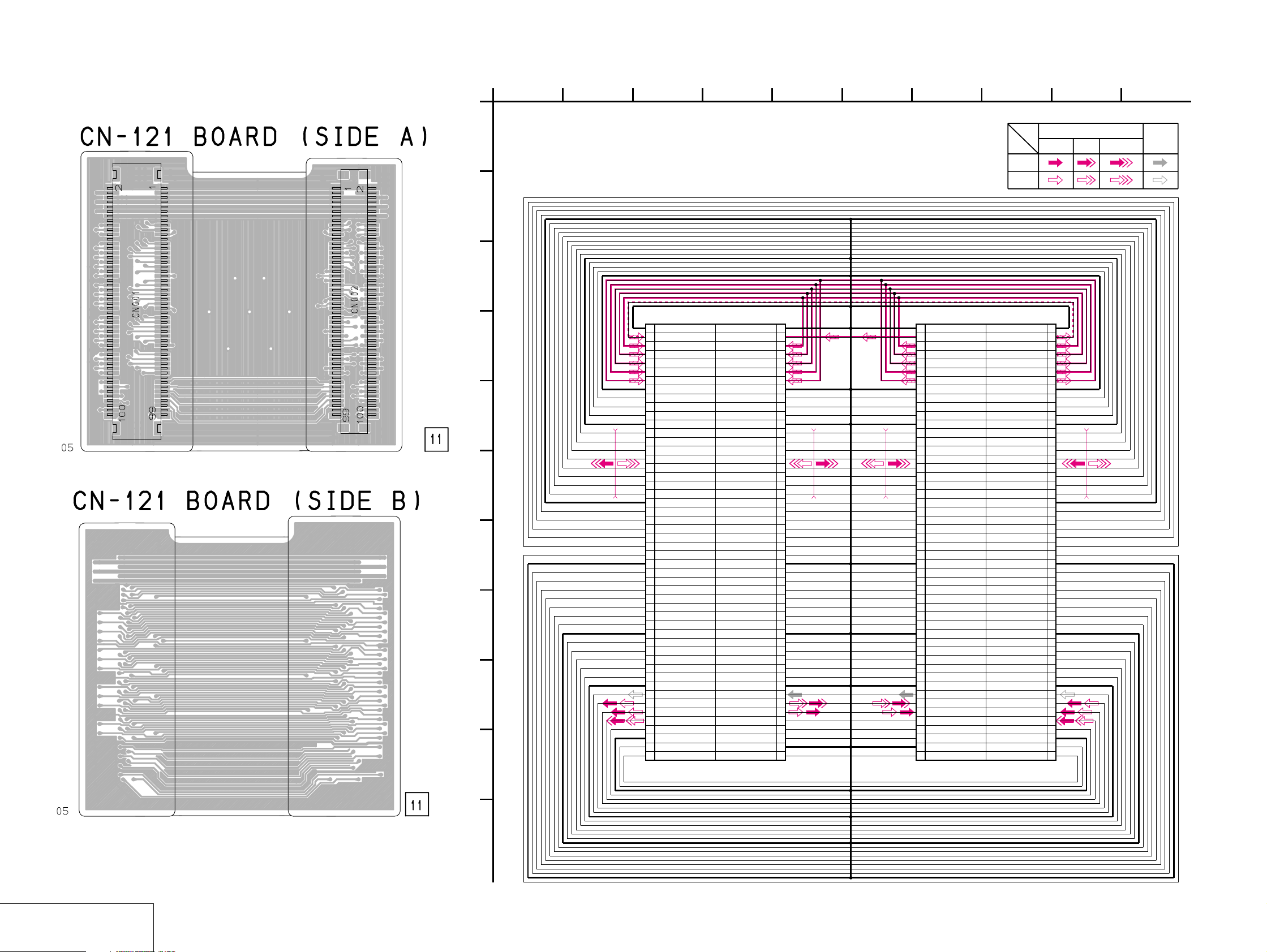
DSC-F505V
CN-121 (CONNECTION) PRINTED WIRING BOARD AND SCHEMATIC DIAGRAM
– Ref. No.: CN-121 board; 1,000 series –
1
38
49
56
72
10
1-678-655-
CN-121 BOARD
CONNECTION
A
-REF.NO.:1,000 SERIES-
B
C
D
E
F
G
H
I
J
2 GND
4 CAM_-7.5V
6 M_5V
8 A_4.9V
10 A_3.2V
12 D_3.2V
14 D_1.8V
16 GND
18 CAM_SO
20 XTG_CS
22 STRB_AIN
24 GND
26 MC_D01
28 MC_D03
30 MC_D05
32 MC_D07
34 MC_D09
36 MC_D11
38 MC_D13
40 MC_D15
42 GND
44 MC_DREQ1
46 MC_DRAK1
48 IRQIMG
50 MC_XCS6
52 MC_XWE0
54 MC_XRD
56 GND
58 MC_A13
60 MC_A11
62 MC_A09
64 MC_A07
66 MC_A05
68 MC_A03
70 MC_A01
72 GND
74 SYS_V
76 XRST_SYS
78 EXT_STRB_ON
80 STRB_PHOTO_ON
82 HDO
84 GND
86 AOUT_L
88 C_OUT
90 PANEL_R-Y
92 PANEL_Y
94 CNT_C
96 GND
98 AU_LRCK
100 DAC_STBY
CN001
100P
CN601
(SEE PAGE 4-18)
SIGNAL PATH
VIDEO SIGNAL
Y Y/CHROMACHROMA
AUDIO
SIGNAL
REC
PB
SY-62 BOARD (2/2)PS-434 BOARD (2/3)
CN805
(SEE PAGE 4-26)
100PCN002
2GND
4CAM_-7.5V
6M_5V
8A_4.9V
10A_3.2V
12D_3.2V
14D_1.8V
16GND
18CAM_SO
20XTG_CS
22STRB_AIN
24GND
26MC_D01
28MC_D03
30MC_D05
32MC_D07
34MC_D09
36MC_D11
38MC_D13
40MC_D15
42GND
44MC_DREQ1
46MC_DRAK1
48IRQIMG
50MC_XCS6
52MC_XWE0
54MC_XRD
56GND
58MC_A13
60MC_A11
62MC_A09
64MC_A07
66MC_A05
68MC_A03
70MC_A01
72GND
74SYS_V
76XRST_SYS
78EXT_STRB_ON
80STRB_PHOTO_ON
82HDO
84GND
86AOUT_L
88C_OUT
90PANEL_R-Y
92PANEL_Y
94CNT_C
96GND
98AU_LRCK
100DAC_STBY
1GND
3CAM_15V
5M_5V
7A_4.9V
9A_3.2V
11D_3.2V
13D_1.8V
15GND
17XCAM_SCK
19XEAGLE/XGCAM_CS
21XCAM_RESET
23GND
25MC_D00
27MC_D02
29MC_D04
31MC_D06
33MC_D08
35MC_D10
37MC_D12
39MC_D14
41MC_HCLK
43MC_DREQ0
45MC_DRAK0
47IRQJPG
49IRQAUDIO
51MC_XCS2
53MC_XWE1
55GND
57MC_A14
59MC_A12
61MC_A10
63MC_A08
65MC_A06
67MC_A04
69MC_A02
71GND
73PEARLFLD
75PAL/XNTSC
77STRB_ON
79PANEL_V
81SP_VOL
83GND
85REC_OUT
87Y_OUT
89PANEL_B-Y
91HALL_AD
93CNT_Y
95LENS_TEMP_AD
97GND
99DAC_ENB
1 GND
3 CAM_15V
5 M_5V
7 A_4.9V
9 A_3.2V
11 D_3.2V
13 D_1.8V
15 GND
17 XCAM_SCK
19 XEAGLE/XGCAM_CS
21 XCAM_RESET
23 GND
25 MC_D00
27 MC_D02
29 MC_D04
31 MC_D06
33 MC_D08
35 MC_D10
37 MC_D12
39 MC_D14
41 MC_HCLK
43 MC_DREQ0
45 MC_DRAK0
47 IRQJPG
49 IRQAUDIO
51 MC_XCS2
53 MC_XWE1
55 GND
57 MC_A14
59 MC_A12
61 MC_A10
63 MC_A08
65 MC_A06
67 MC_A04
69 MC_A02
71 GND
73 PEARLFLD
75 PAL/XNTSC
77 STRB_ON
79 PANEL_V
81 SP_VOL
83 GND
85 REC_OUT
87 Y_OUT
89 PANEL_B-Y
91 HALL_AD
93 CNT_Y
95 LENS_TEMP_AD
97 GND
99 DAC_ENB
CONNECTION
CN-121
1-678-655-
K
05
4-47 4-48
Page 43

FK (CONTROL SWITCH BLOCK) SCHEMATIC DIAGRAM
DSC-F505V
1
38
4
56
72
9
10 11
CONTROL SWITCH BLOCK (FK)
A
B
C
D
E
F
CONTROL SWITCH BLOCK (FK)
is replaced as a block.
so that this PRINTED WIRING BOARD
is omitted.
1
3
5
7
9
11
13
15
17
19
21
23
25
27
29
REG_GND
ZOOM_SW_AD
D_3.2V
XSTRB_LED
REG_GND
REG_GND
REG_GND
REG_GND
LANC_DC
LANC_SIG
XLANC_JACK_IN
REG_GND
REG_GND
KEY_AD1
KEY_AD2
HI-73 BOARD (6/6)
(SEE PAGE 4-41)
R9003
0
R9002
0
R9001
0
CN705
R9011
0
RV001
D006
(FLASH LAMP)
MENU
A
1
LEFT
D
2
COM1
3
COMMON
S001
W
R004
R005
(ZOOM)
(CONTROL BUTTON)
8
COM3
P
B
C
COM2
4
1800
2700
SETUP
7
SW
RIGHT
6
DOWN
5
R007
2700
D004
RD8.2UM-T1B2B3
D005
RD8.2UM-T1B2B3
R008
4700
R9009
0
S004
DISPLAY
S002
(FLASH)
R011
4700
R010
6800
PROGRAM AE
S003
S005
R9008
R9007
LCD
0
BRIGHT(+) BRIGHT(-)
0
R012
39k
R013
6800
S006
LCD BACK LIGHT
1SS387-TPL3
S007
LCD
OFFON
D009
R9012
R9010
0
0
R9006
0
R014
100
30PCN001
REG_GND
REG_GND
PANEL_COM
KEY_AD3
HI_UNREG
LANC_IN
LANC_OUT
EXT_STRB_ON
HSY
RXD
RESET
VDD
TXD
2
4
6
8
10
VG
12
14
16
18
PF7
20
22
24
26
28
30
R002
1800
T
R003
330
TLYU1008(T05,SOY)
LND002
STATIC_GND
NC
1
NC
2
NC
3
REG_GND
4
NC
5
NC
6
HSY
7
PANEL_COM
8
VG
9
HI_UNREG
10
LANC_IN
11
LANC_OUT
12
13
PF7
14
TXD
15
RXD
16
RESET
17
VDD
18
18PCN002
CPC
(FOR CHECK)
CL9001
J9001
(EXT FLASH)
SIGNAL PATH
VIDEO SIGNAL
CHROMA
REC
PB
D9002
-(TX).SO
R9013
470k
D9003
MA4Z082WA
-(TX).SO
FB9002
FB9003
FB9004
FB9005
D9004
MA4Z082WA-(TX).SO
1SS387-TPL3
FB9001
D9005
STATIC_GND
LND001
R9004
0
G
R9005
0
D9001
05
MA4Z082WA
-(TX).SO
MA4Z082WA
H
CONTROL SWITCH BLOCK
4-49 4-50
FK
Page 44

DSC-F505V
R001
4700
R002
100k
D003
D002
U05NU44
C001
10V
22u
C002
0.01u
R003
100
R004
47
C003
1u
R005
22k
Q002
2SB1073-R-TX
Q003
2SB1073-R-TX
Q001
UN5213-TX
D001
MA111-(K8).S0
R7
330
R006
1k
XN1211-TX
Q006
1u
C008
L001
2.2uH
C013 10u
R018
4700
2P
CN002
1 DC_300V
2 REG_GND
T001
1
2
3
4
5
6
160uF
C009
330V
4P
CN001
1
ST_GND
2
ST_UNREG
3
STRB_CHARGE
4
XSTRB_FULL
CL001
CL002
CL003
CL004
CL005
CL006
CL008
CL007
CL020
CL019
1
A
P
F
S
FC0300L
2
B
3564
C
FLASH UNIT (MC)
FLASH UNIT (MC) is replaced as a block.
So that this PRINTED BOARD is omitted.
CN002
DD-148 BOARD
(THROUGH THE
MD-97 HARNESS)
(SEE PAGE 4-45)
B+ SWITCH
SWITCHING
TRANS DRIVE
FLASH
CHARGE
DETECTOR
(THROUGH THE
MS-114 HARNESS)
CN003
FLASH UNIT (ST)
(SEE PAGE 4-51)
78 9
D
05
CF (CONTROL SWITCH BLOCK)/MANUAL FOCUS BLOCK, ST (FLASH UNIT) SCHEMATIC DIAGRAMS PW (CONTROL SWITCH BLOCK), MC (FLASH UNIT) SCHEMATIC DIAGRAMS
1
CONTROL SWITCH BLOCK (CF)/MANUAL FOCUS BLOCK
is replaced as a block.
so that this PRINTED BOARD is omitted.
A
B
C
SY-62 BOARD (2/2)
CN803
(SEE PAGE 4-26)
D
E
D_3.2V
FOCUS_A
FOCUS_B
REG_GND
REG_GND
PHOTOTR_OUT
PHOTOTR_5V
REG_GND
D_3.2V
KEY_AD4
38
CONTROL SWITCH
BLOCK (CF)
CN002
10P
10
9
8
7
6
5
4
3
2
1
05
R006
10k
4
56
72
A
1
CONTROL SWITCH BLOCK (PW)
CONTROL SWITCH BLOCK (PW)
is replaced as a block.
so that this PRINTED WIRING BOARD
is omitted.
MANUAL FOCUS
BLOCK
CN001
6P
REG_GND
FOUCUS_B
FOUCUS_A
D_3.2V
S002
1
2
3
4
5
6
S003S002
WHT-BALSPOT_METER
R003
4700
S003
PHOTOTR_5V
PHOTOTR_OUT
S001
MACRO
R001
1800
R002
2700
S001
1
2
3
4
5
6
CN004
PHOTOTR_5V
PHOTOTR_OUT
REG_GND
FOUCUS_B
FOUCUS_A
D_3.2V
R004
6800
6P
(W/B SET)
S004
S005
R005
39k
S004
LND1
STATIC GND
Q004
PN126S-R
(BRIGHT LEVEL
SENSOR)
S005
FOCUS
AUTO
MANUAL
C004
2200p
(FAR)
RV2
(MANUAL FOCUS)
RV1
(NEAR)
B
C
D
HI-73 BOARD (5/6)
CN704
(SEE PAGE 4-40)
E
21P
CN001
REG_GND
REG_GND
D+
D-
REG_GND
USB_DET
REG_GND
V OUT
REG_GND
AU OUT
AV JACK IN
REG_GND
POWER_LED
SELF_LED
D_3.2V
XPWER_SW
REG_GND
XSHTR_LOCK_SW
XSHTR_SW
MOVIE/XSTILL_SW
XCAM/PB_SW
F
G
38
1
2
3
4
5
6
7
8
9
10
11
12
13
14
15
16
17
18
19
20
21
LND001
STATIC_GND
05
R001
330k
D008
01ZA8.2(TPL3)
MOVIE
LND003
4
D002
01ZA8.2(TPL3)
56
LF001
4
3
1
2
4
3
1
2
LF002
D003
01ZA8.2(TPL3)
R006
1k
1SS387-TPL3
D016
01ZA8.2(TPL3)
STILLMOVIE
COM
LND004
R005
10k
01ZA8.2(TPL3)
D015
R003
680
PLAYS001
D004
TLSU1008(T05,SOY)
(REC LED (RED))
SB-U5338(Rec LED)
PLAY
LND002
D009
01ZA8.2(TPL3)
D017
01ZA8.2(TPL3)
R002
220k
R007
D014
C001
0.1u
R004
330
0
TLGU1008(T05,SOY)
(POWER LED (GREEN))
S003
1
3
01ZA8.2(TPL3)
SB-L5749
S002
S002,S107
(SHUTTER)
D010
D007
S003
POWER
ON/OFF
72
CN002
4P
1 VCC
2D-
3D+
4 GND
J001
A/V OUT
(MONO)
(1st)
2
S107
4
(2nd)
9
DIGITAL
I/O
R008
0
SIGNAL PATH
VIDEO SIGNAL
Y/CHROMA
AUDIO
SIGNAL
REC
PB
1
2
3
FLASH UNIT (ST)
FLASH UNIT (ST) is replaced as a block.
A
B
C
D
CONTROL SWITCH BLOCK/FLASH UNIT
So that this PRINTED BOARD is omitted.
CN003
CN004
05
FLASH UNIT (MC)
CN002
(THROUGH THE
MS-114 HARNESS)
(SEE PAGE 4-52)
SY-62 BOARD (2/2)
CN804
(THROUGH THE
FP-136 FLEXIBLE)
(SEE PAGE 4-26)
CF, PW ST, MC
2P
6P
XSTB_OPEN
2DC_300V
1REG_GND
6
5
4
3
2
1
(OPEN (FLASH) SWITCH)
CL018
CL017
CL016
CL015
CL014
CL013
A_4.9V
A_4.9V
STRB
GND
GND
S001
CL009 CL010
CL011
CL012
S001
Q008
UN5111-TX
B+ SWITCH
Q007
XN1211-TX
SWITCHING FLASH DRIVE FLASH SWITCH
R014
1k
C011
0.047u
Q011
2SD1819A-QRS-TX
R015
150
R012
R013
1M
4-51
564
R016
4.7M
The components identified by mark 0 or dotted
line with mark 0 are critical for safety.
Replace only with part number specified.
Les composants identifiés par une marque 0 sont
critiques pour la sécurité. Ne les remplacer que
par une piéce portant le numéro spécifié.
0.033uF/330V
L002
KP-92
C012
XE_H
LND005
LND006
47
XE_L
Q009
CY25AAJ-8
4-52
Page 45

4-3. WAVEFORMS
CD-283 BOARD
1
125 µsec
IC101 1, 2, 3
2
125 µsec
IC101 4, 5, 6
3
125 µsec
4
IC101 0
7.6 Vp-p
7.6 Vp-p
1.1 Vp-p
3.8 Vp-p
0
qa
qs
qd
112 nsec
IC103 1 – qs
18 MHz
18 MHz
IC103 qh
IC103 wa, ws
3.9 Vp-p
4 Vp-p
4.4 Vp-p
3.2 Vp-p
HI-73 BOARD
1
H
2
H
3
H
4
IC803 8
IC803 9
IC803 0
0.5 Vp-p
0.25 Vp-p
0.22 Vp-p
5 Vp-p
0
qa
qs
qd
H
H
IC901 3
IC901 4
11.7 MHz
IC901 wh
5 Vp-p
5 Vp-p
4.7 Vp-p
3.2 Vp-p
ql
3.2 Vp-p
32.768 kHz
IC405 1
56 nsec
5
56 nsec
6
36.81 MHz (NTSC)
36.56 MHz (PAL)
7
8
IC101 qs
IC101 qd, qf, ql, w;
IC102 wh
18 MHz
IC102 e;
7.6 Vp-p
3 Vp-p
4 Vp-p
3.2 Vp-p
qf
H
125 µsec
IC103 wd
IC103 e;
1.2 Vp-p
5
7
6
8
H
IC803 qf
5 Vp-p
2H
IC803 w;
5 Vp-p
2H
IC803 ws
5 Vp-p
2H
IC803 wf
1.2 Vp-p
H
IC901 ej
qf
4.5 Vp-p
2H
IC902 7
qg
0.5 Vp-p
H
IC651 2
qh
2.1 Vp-p
H
IC651 9
qj
0.6 Vp-p
9
V
IC102 ef
3.2 Vp-p
H
IC102 eg
4-53
9
2H
IC803 ra
qk
5 Vp-p
H
IC901 2
H
IC651 qf
4 Vp-p
20 MHz
IC404 r;
4-55
Page 46

4-4. PARTS LOCATION
DD-148 BOARD
1
495 kHz
IC001 1
1.2 Vp-p
CD-283 BOARD
(SIDE A)
C102 A-2
C103 B-2
C104 B-2
C105 B-3
C106 B-2
C107 B-2
C108 B-2
C109 B-2
C110 C-2
C111 C-1
C112 C-2
C113 A-3
C115 C-3
C116 B-3
C117 B-3
C118 B-3
C119 A-2
C120 A-2
C121 A-2
C122 A-2
C123 A-3
C124 A-2
C125 A-2
C126 A-2
C127 B-3
C128 C-3
C129 A-2
C130 A-2
C131 A-2
C132 A-2
C133 C-3
C134 B-2
C135 A-1
C136 C-3
C138 B-2
C139 C-3
C140 B-3
C141 C-2
CN101 B-1
D101 C-2
D102 A-2
FB101 C-1
FB104 B-3
FB106 B-3
FB107 A-1
FB108 B-1
FB109 B-1
FB110 B-3
FB111 C-3
FB113 C-3
FB114 C-3
IC102 B-3
IC103 A-2
L101 C-2
Q101 A-3
Q102 B-2
Q103 B-3
R101 A-3
R102 B-2
R104 B-2
R105 B-2
R106 B-1
R107 B-2
R108 B-2
R112 A-3
R113 B-2
R114 B-3
R115 B-3
R119 B-3
R126 A-1
R128 A-1
R129 B-1
R138 C-2
R139 A-1
R140 A-1
R141 A-1
R142 A-1
R143 A-1
R144 A-1
R145 A-1
R146 A-1
R147 A-1
R148 A-1
R149 A-1
R150 A-1
R152 B-1
X102 A-3
CD-283 BOARD
(SIDE B)
C114 C-3
C137 A-2
FB103 C-3
FB105 C-3
L102 C-3
L103 A-2
L104 C-3
X101 A-3
HI-73 BOARD
(SIDE A)
BT001 A-1
C253 C-3
C254 C-4
C258 C-4
C259 C-4
C260 C-4
C261 C-4
C262 B-4
C263 C-4
C264 C-4
C265 C-4
C266 C-4
C267 C-4
C269 C-4
C271 B-4
C274 C-4
C278 B-3
C279 B-3
C280 B-3
C282 C-3
C283 C-3
C285 C-3
C286 B-3
C287 B-3
C288 C-4
C289 C-3
C290 C-3
C291 B-3
C292 B-3
C294 C-3
C297 B-3
C298 C-3
C299 B-3
C401 B-3
C402 A-3
C409 B-1
C410 B-1
C411 C-2
C417 B-1
C418 C-1
C426 C-2
C427 C-2
C431 C-2
C432 C-1
C433 C-1
C440 A-2
C441 A-2
C442 D-2
C443 C-2
C446 B-2
C448 C-2
C449 C-2
C601 B-4
C651 C-6
C652 C-5
C653 C-5
C654 D-5
C655 C-5
C656 C-5
C657 D-5
C658 C-5
C659 D-5
C660 D-5
C661 D-5
C662 C-6
C663 C-6
C664 C-6
C801 A-6
C802 A-6
C803 B-6
C804 B-6
C805 B-6
C806 A-6
C807 B-5
C808 B-5
C810 B-5
C811 A-6
C812 B-6
C813 B-6
C814 B-6
C815 B-6
C816 B-6
C903 A-4
C905 A-4
C906 A-5
C907 A-5
C908 A-5
C909 A-5
C911 A-5
C913 A-4
C917 A-3
C918 A-3
CN252 D-2
CN701 B-5
CN702 C-5
CN705 A-2
CN706 D-1
CN707 C-3
CN901 A-3
D401 B-2
D406 B-2
D408 C-1
D410 C-2
D701 B-6
D903 A-5
FB601 A-4
IC253 C-4
IC401 B-3
IC402 C-2
IC404 B-2
IC405 C-2
IC406 C-1
IC407 D-2
IC408 C-2
IC601 B-4
IC651 C-5
IC801 A-5
IC803 B-5
IC901 A-4
L254 D-4
L401 D-2
L651 B-6
L652 C-5
L801 A-6
L802 B-6
L905 A-5
Q254 B-3
Q255 B-3
Q401 A-1
Q405 A-2
Q406 B-1
Q409 C-1
Q410 C-1
Q411 C-1
Q412 C-1
Q413 A-3
Q601 B-4
Q651 C-6
Q652 C-6
Q701 B-6
Q704 D-1
Q705 D-2
Q707 A-3
Q708 A-3
R251 B-4
R254 C-4
R255 C-4
R256 C-4
R259 C-4
R260 C-4
R262 B-4
R263 B-4
R265 B-4
R266 B-4
R270 B-4
R271 B-4
R272 B-4
R273 C-4
R277 C-3
R280 B-3
R281 C-4
R282 C-3
R283 B-3
R284 B-3
R285 B-3
R286 C-4
R287 B-3
R288 C-3
R291 D-2
R292 D-2
R401 A-1
R402 A-1
R404 B-1
R405 A-3
R406 B-3
R407 C-2
R408 C-2
R420 A-2
R422 B-1
R423 A-2
R425 B-1
R426 A-2
R427 B-1
R428 B-1
R429 B-1
R430 A-2
R431 A-2
R432 B-2
R433 B-2
R434 B-2
R435 B-2
R436 B-2
R437 B-1
R438 B-2
R439 B-2
R444 B-1
R445 B-1
R446 C-1
R447 C-1
R448 C-1
R449 B-1
R450 B-2
R451 B-1
R452 B-3
R453 B-2
R454 B-2
R455 B-2
R462 C-3
R463 C-3
R464 C-1
R465 C-3
R466 C-3
R467 C-3
R468 C-3
R469 A-2
R470 B-1
R471 C-1
R472 C-2
R475 C-1
R476 C-2
R478 C-2
R479 D-2
R480 D-2
R483 C-2
R484 C-1
R485 C-2
R487 C-1
R489 C-2
R490 A-2
R491 C-3
R492 C-3
R493 C-3
R494 C-3
R495 B-1
R496 A-1
R497 A-1
R603 B-3
R604 B-4
R605 B-4
R606 B-4
R607 B-4
R608 B-4
R651 C-5
R652 C-5
R653 D-5
R654 D-5
R655 D-6
R656 C-6
R657 C-6
R658 C-6
R701 A-6
R706 D-2
R708 B-5
R709 A-3
R802 B-5
R803 B-5
R804 B-5
R807 A-5
R808 A-5
R809 A-5
R812 A-5
R813 A-5
R815 B-6
R816 B-5
R820 C-5
R821 C-5
R822 C-5
R905 A-5
R908 A-5
R912 A-4
R913 A-5
R914 A-5
R915 A-5
R916 A-5
R918 A-5
R920 A-4
R921 A-5
R922 A-5
R924 A-4
R926 A-5
R940 A-5
R941 A-3
R942 A-3
R943 A-3
R944 A-3
R967 A-3
R968 A-3
R969 A-3
R978 A-5
R979 A-5
R981 A-5
SE401 A-1
X401 B-1
X402 D-1
HI-73 BOARD
(SIDE B)
C255 D-4
C281 D-4
C293 D-3
C295 D-3
C702 B-1
C703 B-1
C704 C-1
C705 C-1
C706 C-1
C707 D-1
C708 D-1
C902 A-2
C904 A-2
C915 A-6
C916 A-3
C919 A-3
C920 A-3
CN251 A-3
CN703 B-4
CN704 A-4
D703 B-1
D705 C-1
D904 A-3
FB703 A-5
FB704 A-5
FB705 A-4
IC701 D-1
IC902 A-5
L252 D-4
L255 D-3
L701 C-1
L703 D-2
L704 D-1
L901 A-2
L902 A-2
L903 A-2
Q253 D-3
Q702 C-1
Q703 B-1
Q706 D-1
Q903 A-6
Q904 A-6
Q905 A-6
Q906 A-6
R279 D-4
R289 A-3
R290 A-3
R702 C-1
R703 A-5
R704 B-1
R705 B-1
R929 A-6
R930 A-6
R932 A-6
R933 A-6
R938 A-6
R939 A-6
4-56
4-58
Page 47

DD-148 BOARD
(SIDE A)
C014 A-2
C015 A-3
C016 A-3
C017 A-3
C018 A-3
C019 B-5
C023 A-5
C025 B-2
C026 B-2
C027 B-5
C028 B-2
C029 A-4
C032 B-5
C034 A-5
C035 A-4
C036 A-5
C039 B-4
C040 A-3
C042 A-3
C043 A-5
C045 A-3
CN001 A-2
CN002 B-1
D001 B-2
D007 B-4
F001 A-1
F002 A-1
F003 A-1
F004 A-1
IC002 A-5
L001 A-5
L002 A-5
L003 B-5
L004 A-4
L005 A-5
LF001 A-1
Q003 A-3
Q005 A-4
Q006 A-4
Q009 A-3
Q010 A-3
Q011 B-2
Q012 B-5
Q021 A-4
Q022 A-5
Q025 B-4
R053 A-2
R055 A-3
R056 A-3
R058 A-3
R060 B-4
R062 A-4
R071 B-4
R072 B-4
R075 A-2
T001 A-3
T002 B-3
T003 B-3
DD-148 BOARD
(SIDE B)
C001 A-1
C002 A-1
C003 A-1
C004 B-1
C005 B-1
C006 A-1
C007 B-1
C008 A-1
C009 A-1
C010 B-2
C011 B-2
C012 A-2
C013 B-2
C022 A-5
C024 B-5
C030 A-4
C033 A-5
C037 B-2
C038 B-2
C041 A-3
C044 A-3
C048 B-5
C049 A-5
C050 B-4
C051 A-3
C052 A-4
C053 A-5
C054 A-3
C056 A-3
C057 B-5
C058 B-4
C059 A-3
C060 A-4
C061 A-4
CN003 B-3
D002 A-5
D003 A-5
D004 A-3
D005 A-3
D006 B-2
IC001 A-1
L006 A-5
L007 A-5
L008 B-5
L009 A-3
L010 B-4
L011 A-4
L012 A-3
L013 A-3
L014 B-5
L015 A-4
L016 A-3
Q004 A-4
Q007 A-5
Q008 A-5
Q013 A-5
Q014 A-1
Q015 A-5
Q016 B-4
Q017 B-4
Q019 B-5
Q020 A-5
Q023 A-4
Q024 A-4
Q030 B-3
Q031 B-3
Q032 B-3
Q033 B-3
R001 B-1
R002 A-1
R003 B-1
R004 B-1
R005 B-1
R006 B-1
R007 B-1
R008 B-1
R010 B-1
R011 A-1
R012 A-1
R013 A-1
R014 A-1
R015 A-1
R016 B-1
R017 B-1
R018 A-2
R020 B-1
R021 B-1
R022 A-1
R023 A-2
R024 A-2
R025 A-2
R026 B-3
R027 A-2
R028 A-2
R029 B-1
R030 A-1
R031 B-4
R032 B-2
R033 A-1
R034 A-1
R035 A-1
R036 B-2
R037 B-2
R038 B-2
R039 B-2
R040 A-1
R041 A-1
R042 A-1
R043 A-1
R044 A-2
R045 A-2
R046 B-2
R047 A-2
R049 A-2
R050 A-2
R051 A-2
R052 B-2
R054 A-5
R057 B-5
R059 A-4
R061 A-5
R063 A-4
R064 A-4
R065 B-4
R066 B-4
R067 B-4
R068 B-4
R069 A-4
R070 A-4
R073 A-4
R074 A-4
R076 B-2
R077 B-3
R078 B-3
R079 B-3
4-59 E
Page 48

Before starting adjustment
EVR Data Re-writing Procedure When Replacing Board
The data that is stored in the repair board, is not necessarily correct.
Perform either procedure 1 or procedure 2 or procedure 3 when replacing board.
Procedure 1
Save the EVR data of the machine in which a board is going to be replaced. Download the saved data after a
board is replaced.
DSC-F505V
SECTION 5
ADJUSTMENTS
(Machine before starting repair)
Save the EVR data
to a personal computer.
PC PC
(Machine after a board is replaced)
Download the saved
data to a machine.
Procedure 2
Remove the EEPROM from the board of the machine tha t is going to be repaired. Install the removed EEPR OM
to the replaced board.
Remove the EEPROM and install it.
(Former board)
(New board)
Procedure 3
When the data cannot be saved due to defective EEPROM, or when the EEPROM cannot be removed or installed, save the data from the same model of the same destination, and download it.
(Machine to be repaired)
Download the data.
Save the data.
(The same model of the same destination)
After the EVR data is saved and downloaded, check the
respective items of the EVR data.
(Refer to page 5-2 for the items to be checked.)
(Machine to be repaired)PC
5-1
Page 49

1-1. Adjusting items when replacing main parts and boards
When replacing main parts and boards, adjust the items indicated by z in the following table.
Block Mounted parts Board
replacement replacement replacement
Replaced parts
Adjustment section Adjustment
Initialization of
7, B, D, E, F, page data
Video Video sync level adj.
Camera Hall adj.
LCD LCD initial data input
System control Battery down adj.
Initialization of D page data
Initialization of 7, B, E, F page data
Video burst level adj.
Flange back adj.
F No. standard data input
Mechanical shutter adj.
Light level adj.
Mixed color cancel adj.
Auto white balance standard data input
Auto white balance ND filter compensation
Auto white balance adj.
Color reproduction adj.
Strobe white balance adj.
CCD (black and white) defect compensation
VCO adj.
D range adj.
Bright adj.
Contrast adj.
Color adj.
V-COM level adj.
V-COM adj.
White balance adj.
ZOOM-VR center adj.
(LCD panel)
(Back light unit)
(CCD imager)
(S/H, AGC, A/D)
(EVR)
(VIDEO AMP)
(LCD drive)
(LCD Timing generator)
(EVR)
(Flash unit)
(Flash unit)
(Control switch block)
LCD901
ND901
IC101
IC103
IC406
IC651
IC803
IC901
IC801
(COMPLETE)
(COMPLETE)
Lens device
MC block
ST block
FK block
LCD block
LCD block
CD-283 board
CD-283 board
PS-434 board
HI-73 board
HI-73 board
HI-73 board
HI-73 board
CD-283 board
PS-434 board
zz
zz zzzz
zz zzzz
zzzzz
zz zzz
zz zzz
zz zzz
zzzzzz
zzzzzz
zz z z z
zz z z z
zz z z z
zz z z z
zz zzz zzz z
zzzz
zz z z
zz zz
zz zz
zz zz
zz zz
zz zz
zzzzz
zz zz zz
zzz
(EEPROM)
(COMPLETE)
(COMPLETE)
IC507
SY-62 board
HI-73 board
SY-62 board
zz
zz
zz
(EEPROM)
IC406
HI-73 board
Table 5-1-1
5-2
Page 50

5-1. CAMERA SECTION ADJUSTMENT
1-1. PREPARATIONS BEFORE ADJUSTMENT
1-1-1. List of Service Tools
• Oscilloscope • Color monitor • Vectorscope
• Regulated power supply • Digital voltmeter
Ref. No.
J-1
Filter for color temperature correction (C14)
J-2
Pattern box PTB-450
J-3
Color bar chart for pattern box
Adjustment remote commander (RM-95 upgraded).
J-4
(Note 1)
J-5
Siemens star chart
J-6
Clear chart for pattern box
J-7
CPC-9 jig (Note 2)
J-8
Mini pattern box
J-9
Extension cable (39P, 0.3 mm)
J-10
Extension cable (39P, 0.3 mm)
J-11
Back ground paper
Note 1: If the micro processor IC in the adjustment remote
commander is not the new micro processor (UPD7503GC56-12), The pages cannot be switched. In this case,
replace with the new micro processor (8-759-148-35).
J-1 J-5J-2
Name
J-3 J-4
Parts Code
J-6080-058-A
J-6082-200-A
J-6020-250-A
J-6082-053-B
J-6080-875-A
J-6080-621-A
J-6082-393-C
J-6082-353-B
J-6082-448-A
1-678-657-11
J-2501-130-A
Auto white balance adjustment/check
White balance adjustment/check
For checking the flange back
For connecting the adjustment remote commander
For adjusting the LCD block
For adjusting the flange back
For extension between the CD-283 board (CN101) and
the PS-434 board (CN602)
For extension between the HI-73 board (CN701, 702) and
the SY-62 board (CN801, 802)
For adjusting the strobe
Note 2: The old CPC-9 jig (Parts code: J-6082-393-B) cannot be
used, because it cannot operate the adjustment remote
commander.
Usage
J-6 J-7
J-11
J-8 J-9 J-10
Fig. 5-1-1
5-3
Page 51

1-1-2. Preparations
Note 1: For details of how remove the cabinet and boards, refer
to “2. DISASSEMBLY”.
Note 2: When performing only the adjustments, the lens block
and boards need not be disassemble.
1) Connect the equipment for adjustments according to Fig. 5-1-
5.
2) Connect the Adjusting remote commander to FK (control
switch block) CN002 via CPC-9 jig (J-6082-393-C). (See Fig.
5-1-3)
Note 3: Setting the “Forced STILL mode power ON” Mode
1) Select page: 0, address: 01, and set data: 01.
2) Select page: D, address: 10, set data: 01, and press
the PAUSE button of the adjusting remote commander.
The Above procedure will enable the camera power
to be turned on. After completing adjustments, be
sure to exit the “Forced STILL mode power ON
Mode”.
Note 4: Exiting the “Forced STILL mode power ON Mode”
1) Select page: 0, address: 01, and set data: 01.
2) Select page: D, address: 10, set data: 00, and press
the PAUSE button of the adjusting remote commander.
3) Select page: 0, address: 01, and set data: 00.
1-1-3. Discharging of the flashlight power supply
The capacitor which is used as power supply of flashlight is charged
with 200 V to 300 V voltage. Discharge this voltage before starting adjustments in order to protect service engineers from electric
shock during adjustment.
Discharge procedure
1. Press the FLASH button (FK block S002) and turn off the
FLASH LED (FK block D006).
2. Fabricate the discharging jig as shown in Fig. 5-1-5 locally by
yourself. Connect the discharging jig to the positive (+) and
negative (–) terminal of the flash voltag e charge capacitor . Allow ten seconds to discharge the voltage.
Flash unit (MC)
Pattern box
About 90 cm
Front of the lens
Fig. 5-1-2
FK (Control switch block)
(CN002)
Two claws
Note 1: Don't use the 12 pin flexible board of CPC-9 jig.
It causes damage to the unit.
Note 2: The old CPC-9 jig (Parts code: J-6082-393-B)
cannot be used, because it cannot operate
the adjustment remote commander.
1
18
CPC-9 jig (J-6082-393-C)
(18p flexible board)
CPC cover
Capacitor
Fig. 5-1-4
Fig. 5-1-5
R: 1 kΩ/1 W
(Part code:
1-215-869-11)
1 kΩ/1 W
Wrap insulating tape.
A
Release knob
Slide the Release knob in the direction of arrow A.
To open the Battery lid.
Fig. 5-1-3
5-4
Page 52

Extension cable
(39P, 0.3 mm)
(J-6082-448-A)
CN602
PS-434 board
CN401
CN601
CN801
CN802
CD-283 board
CN101
Lens block
CN803
CN805
Control switch block (CF)
SY-62 board
CN804
Manual focus block
Video (yellow)
Audio (black)
Color monitor
Vectorscope
Terminated
75 Ω
To HI-73 board,
CN252
To HI-73 board,
CN706
Control
switch block (FK)
CN002
18
1
18
1
CPC-9 jig (Note)
(J-6082-393-C)
Regulated power supply
(6.0 to 7.2 Vdc)
AC power adaptor
Adjustment
remote commander
Battery holder
DD-148 board
CN001
CN003
CN002
CN706
CN252
Flash unit (ST)
Extension cable (39P, 0.3 mm) (1-678-657-11)
Color LCD unit
Inverter
transformer
unit
To Flash unit (MC)
CN002
A/V out jack
To MIC unit
(MIC901)
To Control switch
block (PW)
CN705
CN901
CN704
CN251
CN701
CN702
To Flash unit
(MC) CN001
Memory stick
Note: The old CPC-9 jig (Parts code: J-6082-393-B)
cannot be used, because it cannot operate the
adjustment remote commander.
CN707
HI-73 board
Fig. 5-1-6
5-5
Page 53

1-1-4. Precautions
1. Setting the Switch
Unless otherwise specified, set the switches as follows and perform adjustments.
1. FOCUS button (CF block S005) ......................... MANUAL
2. PROGRAM AE button (FK block S003)
...................................... AUTO (No mark indicated on LCD)
3. DISPLAY button (FK block S004) ..................... OSD OFF
4. P. EFFECT (Menu display) ................................. OFF
2. Order of Adjustments
Basically carry out adjustments in the order given.
5. DEMO (Menu display) ........................................ OFF
6. VIDEO OUT (Menu display) .............................. NTSC
7. WHITE BALANCE (Menu display)................... AUTO
8. EXPOSURE ......................................................... 0EV
9. FLASH LEVEL ................................................... NORMAL
Color bar chart (Color reproduction adjustment frame)
H
Yellow
Cyan
White
Magenta
Green
AB B
A=B
Red
Blue
A
Enlargement
B
A
3. Subjects
1) Color bar chart (Standard picture frame).
When performing adjustments using the color bar chart, adjust the picture frame as shown in Fig. 5-1-7. (Standard picture frame)
2) Clear chart (Standard picture frame)
Remove the color bar chart from the pattern box and insert a
clear chart in its place. (Do not perform zoom operations during this time)
C=D
V
Difference in level
DC
Fig. 5-1-7
Electronic beam scanning frame
Red
Cyan
White
Green
Yellow
Fig. b (monitor TV picture)
Adjust the camera zoom and direction to
obtain the output waveform shown in Fig a
and the monitor TV display shown in Fig. b.
Magenta
Blue
CRT picture frame
5-6
Page 54

4. Preparing the Flash Adjustment Box
A dark room is required to provide an accurate flash adjustment.
If it is not available, prepare the flash adjustment box as given
below;
1) Provide woody board A, B and C of 15 mm thickness.
woody board A (2)
530 mm
1026 mm 1026 mm 1000 mm
woody board B (2)
Fig. 5-1-8
2) Apply black mat paint to one side of woody board A and B.
3) Attach background paper (J-2501-130-A) to woody board C.
4) Assemble so that the black sides and the background paper
side of woody board A, B and C are internal. (Fig 5-1-9)
500 mm
1000 mm1030 mm
woody board A
woody board C (1)
1000 mm
woody board B
woody board A
woody board B
woody board C
Fig. 5-1-9
5-7
Page 55

1-2. INITIALIZATION OF B, D, E, F, 7 PAGE DATA
1-2-1. INITIALIZATION OF D PAGE DATA
1. Initializing D Pag e Data
Note: If the D page data has been initialized, the following
adjustments need to be performed again.
1) Modification of D page data
2) LCD system adjustments
3) Battery end adjustments
Adjusting page D
Adjusting Address 10 to EF
Initializing Method:
1) Select page: 0, address: 01, and set data: 01.
2) Select page: 2, address: 03, and set data: 08.
3) Select page: 2, address: 00, and set data: 2D.
4) Select page: 2, address: 01, set data: 2D, and press the PAUSE
button of the adjustment remote commander.
5) Select page: 2, address: 02, and check that the data changes to
“01”.
6) Perform “Modification of D Page Data”.
2. Modification of D Page Data
If the D page data has been initialized, change the data of the “Fixed
data-2” address shown in the following table by manual input.
Modifying Method:
1) Before changing the data, select page: 0, address: 01, and set
data: 01.
2) New data for changing are not shown in the tables because
they are different in destination. When changing the data, copy
the data built in the same model.
Note : If copy the data built in the different model, the
camcorder may not operate.
3) When changing the data, press the PAUSE button of the
adjustment remote commander each time when setting new
data to write the data in the non-volatile memory.
4) Check that the data of adjustment addresses is the initial value.
If not, change the data to the initial value.
Processing after Completing Modification of D Page data
1) Select page: 2, address: 00, and set data: 29.
2) Select page: 2, address: 01, and set data: 29, and press the
PAUSE button of the adjustment remote commander.
3. D Page Table
Note 1: Fixed data-1: Initialized data.
(Refer to “1. Initializing D Page Data”)
Note 2: Fixed data-2: Modified data.
(Refer to “2. Modification of D Page Data”)
Address Initial value Remark
00 to 0F
10 00 Test mode
11 to 42 Fixed data-1 (Initialized data)
43 Fixed data-2
44 to 61 Fixed data-1 (Initialized data)
62 Fixed data-2
63
64 to 7C F ixed data-1 (Initialized data)
7D Fixed data-2
7E to 85 Fixed data-1 (Initialized data)
86 Fixed data-2
87
88 Fixed data-1 (Initialized data)
89 80 ZOOM-VR center adj.
8A Fixed data-2
8B
8C to 8F Fixed data-1 (Initialized data)
90 80 Battery down adj.
91 88
92 AD
93 C2
94 CD
95 to 97 Fixed data-1 (Initialized data)
98 Fixed data-2
99
9A
9B
9C
9D
9E
9F
A0
A1
A2 Fixed data-1 (Initialized data)
A3 Fixed data-2
A4 Fixed data-1 (Initialized data)
A5 Fixed data-2
A6 to CF Fixed data-1 (Initialized data)
D0 BC Bright adj.
D1 80 Color adj.
D2 B9 White balance adj.
D3 B7
D4 BE Contrast adj.
D5 C8 D Range adj.
D6 7C V-COM Level adj.
D7 80 VCO adj. (NTSC)
D8 74 V-COM adj.
D9 to DC Fixed data-1 (Initialized data)
DD 88 VCO adj. (PAL)
DE to EF Fixed data-1 (Initialized data)
5-8
Page 56

1-2-2. Initializing B, E, F, 7 Page Data
1. Initializing B, E, F, 7 Page Data
Note: If the B, E, F Page data has been initialized, “Modification
of B, E, F, 7 Page Data” and following adjustments need
to be performed again.
1) Modification of B, E, F, 7 page data
2) Video system adjustments
3) Camera system adjustments
Adjusting page F
Adjusting Address 10 to FF
Adjusting page E
Adjusting Address 00 to FF
Adjusting page B
Adjusting Address 00 to FF
Adjusting page 7
Adjusting Address 00 to FF
Initializing Method:
1) Select page: 0, address: 01, and set data: 01.
2) Select page: B, address: 0C, set data: 00, and press the PA USE
button of the adjustment remote commander.
3) Select page: 6, address: 03, and set data: 08.
4) Select page: 6, address: 00, and set data: 2D.
5) Select page: 6, address: 01, set data: 2D, and press the PAUSE
button of the adjustment remote commander.
6) Select page: 6, address: 02, and check that the data changes to
“01”.
7) Perform “Modification of B, E, F, 7 Page Data”.
3. B Page Table
Note 1: Fixed data-1: Initialized data.
(Refer to “1. Initializing B, E, F, 7 Page Data”)
Note 2: Fixed data-2: Modified data.
(Refer to “2. Modification of B, E, F, 7 Page Data”)
Address Initial value Remar k
00 Fixed data-2
01 to FF Fixed data-1 (Initialized data)
4. E Page Table
Note 1: Fixed data-1: Initialized data.
(Refer to “1. Initializing B, E, F, 7 Page Data”)
Note 2: Fixed data-2: Modified data.
(Refer to “2. Modification of B, E, F, 7 Page Data”)
Address Initial value Remar k
00 to FF Fixed data-1 (Initialized data)
2. Modification of B, E, F, 7 Page Data
If the B, E, F, 7 Page data has been initialized, change the data of
the “Fixed da ta-2” address shown in the following tables by manual
input.
Modifying Method:
1) Before changing the data, select page: 0, address: 01, and set
data: 01.
2) New data for changing are not shown in the tables because
they are different in destination. When changing the data, copy
the data built in the same model.
Note: If copy the data built in the different model, the
camcorder may not operate.
3) When changing the data, press the PAUSE button of the
adjustment remote commander each time when setting new
data to write the data in the non-volatile memory.
4) Check that the data of adjustment addresses is the initial value.
If not, change the data to the initial value.
Processing after Completing Modification of B, E, F , 7 P age data
1) Select page: 2, address: 00, and set data: 29.
2) Select page: 2, address: 01, and set data: 29, and press the
PAUSE button of the adjustment remote commander.
5-9
Page 57

5. F Page Table
Note 1: Fixed data-1: Initialized data. (Refer to “1. Initializing B, E, F, 7 Page Data”)
Note 2: Fixed data-2: Modified data. (Refer to “2. Modification of B, E, F, 7 Page Data”)
Address Initial value Remar k
00 to 0F
10 to13 Fixed data-1 (Initialized data)
14 1C Flange back adj.
15 94
16 26
17 EC
18 13
19 B9
1A 00
1B 00
1C 00
1D 00
1E 46
1F 00
20 20
21 20
22 20
23 44
24 0A
25 00
26 85 Light level adj.
27 Fixed data-1 (Initialized data)
28 94 Light level adj.
29 47 F No. standard data input
2A 41
2B 3D
2C 3D
2D 3B
2E 80 Hall adj.
2F 93
30 to 33 Fixed data-1 (Initialized data)
34 15 Hall adj.
35 7C
36 to 39 Fixed data-1 (Initialized data)
3A 2F Auto white balance standard data input
3B 37
3C 40
3D D0
3E Fixed data-1 (Initialized data)
3F B5 Auto white balance adj.
40 43
41 03 Color reproduction adj.
42 E9
43 63
44 83
45 D5
46 FE
47 73
48 45
49 to 4C Fixed data-1 (Initialized data)
4D 27 Strobe white balance adj.
4E 77
4F 00 Auto white balance ND filter
50 00 compensation adj.
Address Initial value Remar k
51 03 Color reproduction adj.
52 E9 (with ND filter)
53 63
54 83
55 D5
56 FE
57 73
58 45
59 00 Auto white balance standard data input
5A 14 Mechanical shutter adj.
5B Fixed data-1 (Initialized data)
5C 63 Color reproduction adj.
5D 83
5E 03
5F E9
60 63 Color reproduction adj.
61 83 (with ND filter)
62 03
63 E9
64 10 Strobe white balance adj.
65 61 Video sync level adj.
66 61 Video burst level adj.
67, 68 Fixed data-1 (Initialized data)
69 01 Strobe white balance adj.
6A A3
6B B4
6C 0B Mechanical shutter adj.
6D C2
6E 09
6F 42
70 06
71 C2
72 05
73 C2
74 04
75 C2
76 33
77 33
78 33
79 33
7A 33
7B 33
7C 33
7D 33
7E 33
7F 33
80 00 Auto white balance adj.
81 to 9F Fixed data-1 (Initialized data)
A0 00 Mixed color cancel adj.
A1 00
A2 00
A3 00
A4 to FF Fixed data-1 (Initialized data)
5-10
Page 58

6. 7 Page Table
Note 1: Fixed data-1: Initialized data. (Refer to “1. Initializing B, E, F, 7 Page Data”)
Note 2: Fixed data-2: Modified data. (Refer to “2. Modification of B, E, F, 7 Page Data”)
Address Initial value Remar k
00 to 5F Fixed data-1 (Initialized data)
60 0F CCD black defect compensation
61 FF
62 0F
63 FF
64 0F
65 FF
66 0F
67 FF
68 0F
69 FF
6A 0F
6B FF
6C 0F
6D FF
6E 0F
6F FF
70 0F
71 FF
72 0F
73 FF
74 0F
75 FF
76 0F
77 FF
78 0F
79 FF
7A 0F
7B FF
7C 0F
7D FF
7E 0F
7F FF
80 0F
81 FF
82 0F
83 FF
84 0F
85 FF
86 0F
87 FF
88 0F CCD white defect compensation
89 FF
8A 0F
8B FF
8C 0F
8D FF
8E 0F
8F FF
90 0F
91 FF
92 0F
Address Initial value Remar k
93 FF CCD white defect compensation
94 0F
95 FF
96 0F
97 FF
98 0F
99 FF
9A 0F
9B FF
9C 0F
9D FF
9E 0F
9F FF
A0 0F
A1 FF
A2 0F
A3 FF
A4 to FF Fixed data-1 (Initialized data)
5-11
Page 59

1-3. VIDEO SYSTEM ADJUSTMENTS
1. Video Sync Level Adjustment
Adjust the sync level of the composite video signal output.
Mode PLAY
Signal Color bar (Test signal)
Measurement Point Video terminal of A/V OUT jack
(75 Ω terminated)
Measuring Instrument Oscilloscope
Adjustment Page F
Adjustment Address 65
Specified Value A = 286 ± 5 mV (NTSC)
A = 300 ± 5 mV (PAL)
Menu setting:
1) VIDEO OUT of SET UP menu
...................................... NTSC (NTSC mode)
...................................... PAL (PAL mode)
Adjusting method:
1) Select page: 0, address: 01, and set data: 01.
2) Select page: 5, address: F1, and set data: 04.
3) Select page: F, address: 65, change the data and set the sync
level (A) to the specified value.
4) Press the PAUSE button of the adjusting remote commander.
Processing after Completing Adjustments:
1) Select page: 5, address: F1, and set data: 00.
2) Select page: 0, address: 01, and set data: 00.
2. Video Burst Level Adjustment
Adjust the burst level of the composite video signal output.
Mode PLAY
Signal Color bar (Test signal)
Measurement Point Video terminal of A/V OUT jack
(75 Ω terminated)
Measuring Instrument Oscilloscope
Adjustment Page F
Adjustment Address 66
Specified Value A = 286 ± 5 mV (NTSC)
A = 300 ± 5 mV (PAL)
Menu setting:
1) VIDEO OUT of SET UP menu
...................................... NTSC (NTSC mode)
...................................... PAL (PAL mode)
Adjusting method:
1) Select page: 0, address: 01, and set data: 01.
2) Select page: 5, address: F1, and set data: 04.
3) Select page: F, address: 66, change the data and set the burst
level (A) to the specified value.
4) Press the PAUSE button of the adjusting remote commander.
Processing after Completing Adjustments:
1) Select page: 5, address: F1, and set data: 00.
2) Select page: 0, address: 01, and set data: 00.
A
H
H
Fig. 5-1-10 Fig. 5-1-11
A
5-12
Page 60

1-4. CAMERA SYSTEM ADJUSTMENT
Before perform the camera system adjustments, check that the
specified values of “VIDEO SYSTEM ADJUSTMENTS” are
satisfied.
1. HALL Adjustment
For detecting the position of lens iris, adjust the HALL AMP
gain and offset.
Mode STILL
Subject Not required
Measurement Point Displayed data of page: 1 (Note 2)
Measuring Instrument Adjusting remote commander
Adjustment Page F
Adjustment Address 2E, 2F, 34, 35
Specified Value 13 to 17 during IRIS OPEN
7B to 7F during IRIS CLOSE
Note 1: Check that the data of page: 6, address: 02 is “00”.
If not, turn the power of the unit OFF/ON.
Note 2: The right two digits of the page: 1 displayed data of the
adjusting remote commander.
1:00:XX
Displayed data
Adjusting method:
1) Select page: 0, address: 01, and set data: 01.
2) Select page: 5, address: F1, and set data: FF.
3) Select page: D, address: 63, set data: 40, and press the PAUSE
button of the adjusting remote commander.
4) Select page: 6, address: 94, and set data: 15.
5) Select page: 6, address: 95, and set data: 7D.
6) Select page: 6, address: 01, set data: 6D, and press the PAUSE
button. (The HALL adjustment is performed and the adjustment
data is stored in page: F, addresses: 2E, 2F, 34 and 35)
7) Select page: 6, address: 02, and check that the data is “01”.
8) Select page: 6, address: 01, set data: 00, and press the PAUSE
button.
Checking method:
1) Select page: 0, address: 03, and set data: 03.
2) Select page: 6, address: 01, set data: 01, and press the PAUSE
button of the adjusting remote commander.
3) Select page: 1, and check that the displayed data (Note 2) during
IRIS OPEN satisfies the specified value.
4) Select page: 6, address: 01, set data: 03, and press the PAUSE
button.
5) Select page: 1, and check that the displayed data (Note 2) during
IRIS CLOSE satisfies the specified value.
Processing after Completing Adjustments:
1) Select page: 0, address: 03, and set data: 00.
2) Select page: 6, address: 01, set data: 00, and press the PAUSE
button of the adjusting remote commander.
3) Select page: 6, address: 95, and set data: 00.
4) Select page: 6, address: 94, and set data: 00.
5) Select page: 5, address: F1, and set data: 00.
6) Select page: D, address: 63, set data: 00, and press the PAUSE
button.
7) Select page: 0, address: 01, and set data: 00.
5-13
Page 61

2. Flange Back Adjustment
(Using the minipattern box)
The inner focus lens flange back adjustment is carried out automatically. In whichever case, the focus will be deviated during
auto focusing/manual forcusing.
Mode STILL
Subject Siemens star chart with ND filter
for minipattern box (Note 1)
Measurement Point Check operation on TV monitor
Measuring Instrument
Adjustment Page F
Adjustment Address 14 to 25
Adjusting method:
1) Install the minipattern box so that the distance between it
and the front of lens of the camera is less than 3cm.
2) Make the height of minipattern box and the camera equal.
3) Check the output voltage of the regulated power supply is
the specified voltage ± 0.01 Vdc.
4) Check that the center of Siemens star chart meets the center
of shot image screen with the zoom lens at TELE end and
WIDE end respectively.
5) Select page: 0, address: 01, and set data: 01.
6) Select page: 5, address: F1, and set data: FF.
7) Select page: D, address: 63, set data: 40, and press the PA USE
button of the adjusting remote commander.
8) Check that the data on page: F, addresses: 14 to 25 are initial
values (See table below).
Note 1: Dark Siemens star chart.
Note 2: Check that the data of page: 6, address: 02 is “00”.
If not, turn the power of the unit OFF/ON.
Preparations before adjustments:
The minipattern box is installed as shown in the following figure.
Note 3: The attachment lenses are not used.
Note 4: Take car e not to hit the mini-pattern box when extending
the lens.
Specified voltage:The specified voltage varies according to the
minipatternbox, so adjustment the power sup
ply output voltage to the specified voltage
written on the sheet which is supplied with the
minipattern box.
Below 3 cm
Minipattern box
Camera
Camera
table
Output voltage : Specified voltage ±0.01 Vdc
Regulated power supply
Output current : more than 3.5 A
Address Data Address Data
14 1C 1D 00
15 94 1E 46
16 26 1F 00
17 EC 20 20
18 13 21 20
19 B9 22 20
1A 00 23 44
1B 00 24 0A
1C 00 25 00
9) Select page: 6, address: 01, set data: 13, and press the P AUSE
button.
10) Select page: 6, address: 01, set data: 27, and press the PA USE
button. (The flange back adjustment is performed and the
adjustment data is stored in page: F, addresses: 14 to 25)
11) Select page: 6, address: 02, and check that the data is “01”.
Processing after completion of adjustment:
1) Select page: 6, address: 01, set data: 00, and press the P AUSE
button of the adjusting remote commander.
2) Select page: 5, address: F1, and set data: 00.
3) Select page: D, address: 63, set data: 00, and press the PA USE
button.
4) Select page: 0, address: 01, and set data: 00.
5) Perform “Flange Back Check”.
Red (+)
Black (–)
Yellow (SENS +)
White (SENS –)
Black (GND)
Need not connected
Fig. 5-1-12
5-14
Page 62

3. Flang e Back Check
Mode STILL
Subject Siemens star
(2.0 m from the front of the lens)
(Luminance: approx. 200 lux)
Measurement Point Check operation on TV monitor
Measuring Instrument
Specified value Focused at the TELE end and
WIDE end
Checking method:
1) Place the Siemens star 2.0 m from the front of the lens.
2) To open the IRIS, decrease the luminous intensity to the Siemens star up to a point before noise appear on the image.
3) Select page: 0, address: 01, and set data: 01.
4) Select page: 5, address: F1, and set data: FF.
5) Select page: D, address: 63, set data: 40, and press the PA USE
button of the adjusting remote commander.
6) Shoot the Siemens star with the zoom TELE end.
7) Turn on the auto focus.
8) Check that the lens is focused.
9) Select page: 6, address: 2C, and set data: 01.
10) While observe the TV monitor, change the zoom to the WIDE
end and check that the lens is focused.
Processing after completion of adjustment:
1) Select page: 6, address: 2C, and set data: 00.
2) Select page: 5, address: F1, and set data: 00.
3) Select page: D, address: 63, set data: 00, and press the PA USE
button of the adjusting remote commander.
4) Select page: 0, address: 01, and set data: 00.
5-15
Page 63

4. F No. Standard Data Input
Compensate the unevenness of the iris meter sensitivity.
Mode STILL
Subject Clear chart
(10 cm from the front of the lens)
Adjustment Page F
Adjustment Address 29 to 2D
Note 1: Check that the data of page: 6, address: 02 is “00”.
If not, turn the power of the unit OFF/ON.
Adjusting method:
1) Shoot the Clear chart with the zoom WIDE end.
2) Select page: 0, address: 01, and set data: 01.
3) Select page: 5, address: F1, and set data: FF.
4) Select page: D, address: 63, set data: 40, and press the PA USE
button of the adjusting remote commander.
5) Select page: E, address: 51, after noting down the data, set
data: FF, and press the PAUSE button.
6) Select page: 6, address: 01, set data: BB, and press the PA USE
button. (The F No. standard data input is performed and the
standard data is stored in page: F, addresses: 29 to 2D)
7) Select page: 6, address: 02, and check that the data is “01”.
Processing after Completing Adjustments:
1) Select page: 6, address: 01, set data: 00, and press the P AUSE
button of the adjusting remote commander.
2) Select page: E, address: 51, set data noted down at step 5)
and press the PAUSE button.
3) Select page: 5, address: F1, and set data: 00.
4) Select page: D, address: 63, set data: 00, and press the PA USE
button.
5) Select page: 0, address: 01, and set data: 00.
5. Mechanical Shutter Adjustment
Adjust the period which the mechanical shutter is closed,
and compensate the exposure.
Mode STILL
Subject Clear chart
(10 cm from the front of the lens)
Adjustment Page F
Adjustment Address 5A, 6C to 7F
Note 1: Check that the data of page: 6, address: 02 is “00”.
If not, turn the power of the unit OFF/ON.
Adjusting method:
1) Shoot the Clear chart with the zoom WIDE end.
2) Select page: 0, address: 01, and set data: 01.
3) Select page: 5, address: F1, and set data: FF.
4) Select page: D, address: 63, set data: 40, and press the PA USE
button of the adjusting remote commander.
5) Select page: 6, address: 01, set data: AD, and press the P A USE
button. (The mechanical shutter adjustment is performed and
the adjustment data is stored in page: F, addresses: 5A and
6C to 7F)
6) Select page: 6, address: 02, and check that the data is “01”.
7) Select page: 6, address: AB, and check that the data is “00”.
(If the data other than “00”, mechanical shutter adjustment
has errors)
Processing after Completing Adjustments:
1) Select page: 6, address: 01, set data: 00, and press the P AUSE
button of the adjusting remote commander.
2) Select page: 5, address: F1, and set data: 00.
3) Select page: D, address: 63, set data: 00, and press the PA USE
button.
4) Select page: 0, address: 01, and set data: 00.
5-16
Page 64

6. Picture Frame Setting
Color bar chart picture frame
TV monitor picture frame
E=F
V
EF
Check on the oscilloscope
Mode STILL
Subject Color bar chart
(Color reproduction adjustment frame)
Measurement Point Video terminal of A/V OUT jack
(75 Ω terminated)
Measuring Instrument Oscilloscope and TV monitor
Specified Value A = B, C = D, E = F
Note 1: Displayed data of page 1 of adjusting remote commander.
1:XX:XX
XL or YL data
XH or YH data
Setting method:
1) Select page: 5, address: F1, and set data: FF.
2) Adjust the zoom and the camera direction, and set to the picture frame to the specified position.
3) Mark the position of the picture frame on the TV monitor,
and adjust the picture frame to this position in following adjustments using “Color reproduction adjustment frame”.
4) Select page: 0, address: 03, and set data: 18.
5) Select page: 1, and note down the XH and XL data. (Note 1)
6) Select page: 0, address: 03, and set data: 22.
7) Select page: 1, and note down the YH and YL data. (Note 1)
8) Select page: 5, address: F1, and set data: 00.
1. Horizontal period
A=B
B
A
2. Vertical period
C=D
C
D
Fig. 5-1-13
How to reset the zoom and focus when they deviated:
If the zoom and focus deviated due to some reason, reset them in
the following method.
1) Select page: 6, address: 90, and set data: XL. (Note 2)
2) Select page: 6, address: 91, and set data: XH. (Note 2)
3) Select page: 6, address: 92, and set data: YL. (Note 3)
4) Select page: 6, address: 93, and set data: YH. (Note 3)
5) Select page: 6, address: 01, set data: 79, press the PAUSE
button.
6) Wait for 1 second.
7) Select page: 6, address: 2C, and set data: 01.
8) Select page: 6, address: 01, set data: 00, and press the PA USE
button.
Note 2: The data noted down at step 5) of “Setting method”.
Note 3: The data noted down at step 7) of “Setting method”.
Fig. 5-1-14
Check on the TV monitor
Fig. 5-1-15
5-17
Page 65

7. Light Level Adjustment and ND Shutter Check
Adjust the standard LV value.
Mode STILL
Subject Clear chart
(Color reproduction adjustment frame)
Measurement Point Displayed data of page: 1 (Note 2)
Measuring Instrument Adjusting remote commander
Adjustment Page F
Adjustment Address 26, 28
Specified Value AE level 1: 0FE0 to 1020
AE level 2: Below 1100
Note 1: Check that the data of page: 6, address: 02 is “00”.
If not, turn the power of the unit OFF/ON.
Note 2: The right four digits of the page: 1 displayed data of the
adjusting remote commander.
1:XX:XX
Displayed data
Adjusting method:
1) Select page: 0, address: 01, and set data: 01.
2) Select page: 5, address: F1, and set data: FF.
3) Select page: D, address: 63, set data: 40, and press the PA USE
button of the adjusting remote commander.
4) Select page: 6, address: 01, set data: 0D, and press the PA USE
button. (The light level adjustment is performed and the adjustment data is stored in page: F, addresses: 26 and 28)
5) Select page: 6, address: 02, and check that the data is “01”.
6) Select page: 0, address: 03, and set data: 06.
7) Select page: 1, and check that the displayed data (Note 2)
satisfies the AE level 1 specified value.
8) Select page: E, address: 41, set data: 6B, and press the P AUSE
button.
9) Select page: 6, address: 1C, and set data: 03.
10) Select page: 1, and check that the displayed data (Note 2)
satisfies the AE level 2 specified value.
8. Mixed Color Cancel Adjustment
To perform mixed color cancel adjustment based on data of each
color in color bar.
Mode STILL
Subject Color bar chart
(Color reproduction adjustment frame)
Adjustment Page F
Adjustment Address A0 to A3
Note 1: Perform “Light Level Adjustment” before this
adjustment.
Note 2: Check that the data of page: 6, address: 02 is “00”.
If not, turn the power of the unit OFF/ON.
Adjusting method:
1) Select page: 0, address: 01, and set data: 01.
2) Select page: 5, address: F1, and set data: FF.
3) Select page: D, address: 63, set data: 40, and press the PA USE
button of the adjusting remote commander.
4) Select page: 6, address: 01, set data: D7, and press the PA USE
button.
5) Select page: 6, address: 01, set data: D5, and press the PA USE
button. (The mixed color adjustment is performed and the
adjustment data is stored in page: F, addresses: A0 to A3)
6) Select page: 6, address: 02, and check that the data is “01”.
Processing after Completing Adjustments:
1) Select page: 6, address: 01, set data: 00, and press the P AUSE
button of the adjusting remote commander.
2) Select page: 5, address: F1, and set data: 00.
3) Select page: D, address: 63, set data: 00, and press the PA USE
button.
4) Select page: 0, address: 01, and set data: 00.
Processing after Completing Adjustments:
1) Select page: 6, address: 1C, and set data: 00.
2) Select page: E, address: 41, set data: 6A, and press the PA USE
button of the adjusting remote commander.
3) Select page: 0, address: 03, and set data: 00.
4) Select page: 6, address: 01, set data: 00, and press the P AUSE
button.
5) Select page: 5, address: F1, and set data: 00.
6) Select page: D, address: 63, set data: 00, and press the PA USE
button.
7) Select page: 0, address: 01, and set data: 00.
5-18
Page 66

9. Auto White Balance Standard Data Input
Adjust the white balance standard data at 3200K.
Mode STILL
Subject Clear chart
(Color reproduction adjustment frame)
Adjustment Page F
Adjustment Address 3A to 3D, 59
Note 1: Perform “Light Level Adjustment” and “Mixed Color
Cancel Adjustment” before this adjustment.
Note 2: Check that the data of page: 6, address: 02 is “00”.
If not, turn the power of the unit OFF/ON.
Adjusting method:
1) Select page: 0, address: 01, and set data: 01.
2) Select page: 5, address: F1, and set data: FF.
3) Select page: D, address: 63, set data: 40, and press the PA USE
button of the adjusting remote commander.
4) Select page: 6, address: 01, set data: 11, and press the PA USE
button.
5) Select page: 6, address: 01, set data: 0B, and press the P AUSE
button. (The auto white balance standard data input is performed and the standard data is stored in page: F, addresses:
3A to 3D, 59)
6) Select page: 6, address: 02, and check that the data is “01”.
Processing after Completing Adjustments:
1) Select page: 6, address: 01, set data: 00, and press the PA USE
button of the adjusting remote commander.
2) Select page: 5, address: F1, and set data: 00.
3) Select page: D, address: 63, set data: 00, and press the PA USE
button.
4) Select page: 0, address: 01, and set data: 00.
5) Perform “Auto White Balance Adjustment”.
10. Auto White Balance ND Filter Compensation
Adjust to the proper auto white balance output data with Built-in
ND filter.
If it is not correct, auto white balance and color reproducibility
will be poor.
Mode STILL
Subject Clear chart
(Color reproduction adjustment frame)
Adjustment Page F
Adjustment Address 4F , 50
Note 1: Perform “Auto White Balance Standard Data Input” be-
fore this adjustment.
Note 2: Check that the data of page: 6, address: 02 is “00”. If
not, turn the power of the unit OFF/ON.
Adjusting method:
1) Select page: 0, address: 01, and set data: 01.
2) Select page: 5, address: F1, and set data: FF.
3) Select page: D, address: 63, set data: 40, and press the PAUSE
button of the adjusting remote commander.
4) Select page: 6, address: 1C, set data: 03, and press the PAUSE
button.
5) Wait for 1 second.
6) Select page: 6, address: 01, set data: 11, and press the PAUSE
button.
7) Select page: 6, address: 01, set data: 09, and press the PAUSE
button.
(The auto white balance adjustment ND filter compensation is
performed and the adjustment data is stored in page: F,
addresses: 4F and 50)
8) Select page: 6, address: 02, and check that the data is “01”.
Processing after Completing Adjustments:
1) Select page: 6, address: 1C, and set data: 00.
2) Select page: 6, address: 01, set data: 00, and press the PAUSE
button of the adjusting remote commander.
3) Select page: 5, address: F1, and set data: 00.
4) Select page: D, address: 63, set data: 00, and press the PAUSE
button.
6) Select page: 0, address: 01, and set data: 00.
5-19
Page 67

11. Auto White Balance Adjustment
Adjust to the proper auto white balance output data.
If it is not correct, auto white balance and color reproducibility
will be poor.
Mode STILL
Subject Clear chart
(Color reproduction adjustment frame)
Filter Filter C14 for color temperature
correction
Measurement Point Displayed data of page: 1 (Note 3)
Measuring Instrument Adjusting remote commander
Adjustment Page F
Adjustment Address 3F, 40, 80
Specified Value R ratio: 2820 to 2A60
B ratio: 5DA0 to 5EE0
Note 1: Perform “Auto White Balance Standard Data Input” and
“Auto White Balance ND Filter Compensation” before
this adjustment.
Note 2: Check that the data of page: 6, address: 02 is “00”.
If not, turn the power of the unit OFF/ON.
Note 3: The right four digits of the page: 1 displayed data of the
adjusting remote commander.
1:XX:XX
Displayed data
Adjusting method:
1) Place the C14 filter for color temperature correction on the
lens.
2) Select page: 0, address: 01, and set data: 01.
3) Select page: 5, address: F1, and set data: FF.
4) Select page: D, address: 63, set data: 40, and press the PA USE
button of the adjusting remote commander.
5) Select page: 6, address: 01, set data: A7, and press the P A USE
button.
6) Select page: F, addresses: 49 to 4C, and noting do wn the data
of each address.
7) Write data in page: F, addresses: 49 to 4C as shown in the
following table.
Adderss 49 4A 4B 4C
Data 29 C0 5E 40
Note: After setting each data, be sure to press the PAUSE button
of the adjusting remote commander.
8) Select page: 6, address: 01, set data: A5, and press the P A USE
button. (The auto white balance adjustment is performed and
the adjustment data is stored in page: F, addresses: 3F, 40
and 80)
9) Select page: 6, address: 02, and check that the data is “01”.
10) Select page: 6, address: 01, set data: 3F, and press the P A USE
button.
11) Select page: 0, address: 03, and set data: 04.
12) Select page: 1, and check that the displayed data (Note 3)
satisfies the R ratio specified value.
13) Select page: 0, address: 03, and set data: 05.
14) Select page: 1, and check that the displayed data (Note 3)
satisfies the B ratio specified value.
15) Select page: F, addresses: 49 to 4C, and input the data noted
down at step 6).
Note: After setting each data, be sure to press the PAUSE button
of the adjusting remote commander.
Processing after Completing Adjustments:
1) Select page: 0, address: 03, and set data: 00.
2) Select page: 6, address: 01, set data: 00, and press the P AUSE
button of the adjusting remote commander.
3) Select page: 5, address: F1, and set data: 00.
4) Select page: D, address: 63, set data: 00, and press the PA USE
button.
5) Select page: 0, address: 01, and set data: 00.
5-20
Page 68

12. Color Reproduction Adjustment
Adjust the color separation matrix coefficient so that proper color
reproduction is produced.
12-1. Color Reproduction Adjustment (Without ND Filter)
Mode STILL
Subject Color bar chart
(Color reproduction adjustment frame)
Adjustment Page F
Adjustment Address 41 to 48, 5C to 5F
Note 1: Perform “Auto White Balance Standard Data Input”
before this adjustment.
Note 2: Check that the data of page: 6, address: 02 is “00”.
If not, turn the power of the unit OFF/ON.
Adjusting method:
1) Select page: 0, address: 01, and set data: 01.
2) Select page: 5, address: F1, and set data: FF.
3) Select page: D, address: 63, set data: 40, and press the PA USE
button of the adjusting remote commander.
4) Select page: B, address: 67, after noting down the data, set
data: 00, and press the PAUSE button.
5) Select page: 6, address: 01, set data: AB, and press the P A USE
button.
6) Select page: 6, address: 12, set data: 80, and press the PA USE
button.
7) Wait for 1 second.
8) Select page: 6, address: 12, set data: 00, and press the PA USE
button.
9) Wait for 2 seconds.
10) Select page: 6, address: 01, set data: A9, and press the PAUSE
button. (The color reproduction adjustment (without ND filter) is performed and the adjustment data is stored in page:
F, addresses: 41 to 48, 5C to 5F)
11) Select page: 6, address: 02, and check that the data is “01”.
Processing after Completing Adjustments:
1) Select page: 6, address: 01, set data: 00, and press the PA USE
button of the adjusting remote commander.
2) Select page: B, address: 67, set data noted down at step 4)
and press the PAUSE button.
3) Select page: 5, address: F1, and set data: 00.
4) Select page: D, address: 63, set data: 00, and press the PA USE
button.
5) Select page: 0, address: 01, and set data: 00.
6) Perform “Color Reproduction Check”.
12-2. Color Reproduction Adjustment (With ND Filter)
Mode STILL
Subject Color bar chart
(Color reproduction adjustment frame)
Adjustment Page F
Adjustment Address 51 to 58, 60 to 63
Note 1: Perform “Auto White Balance Standard Data Input” and
“Auto White Balance ND Filter Compensation” before
this adjustment.
Note 2: Check that the data of page: 6, address: 02 is “00”. If
not, turn the power of the unit OFF/ON.
Adjusting method:
1) Select page: 0, address: 01, and set data: 01.
2) Select page: 5, address: F1, and set data: FF.
3) Select page: D, address: 63, set data: 40, and press the PA USE
button of the adjusting remote commander.
4) Select page: B, address: 67, after noting down the data, set
data: 00, and press the PAUSE button.
5) Select page: 6, address: 1C, set data: 03, and press the PA USE
button.
6) Wait for 1 second.
7) Select page: 6, address: 01, set data: C3, and press the PA USE
button.
8) Select page: 6, address: 12, set data: 80, and press the PA USE
button.
9) Wait for 1 second.
10) Select page: 6, address: 12, set data: 00, and press the PA USE
button.
11) Wait for 2 seconds.
12) Select page: 6, address: 01, set data: C1, and press the P A USE
button.
(The color reproduction adjustment (with ND filter) is performed and the adjustment data is stored in page: F , addresses:
51 to 58 and 60 to 63)
13) Select page: 6, address: 02, and check that the data is “01”.
Processing after Completing Adjustments:
1) Select page: 6, address: 01, set data: 00, and press the PA USE
button of the adjusting remote commander.
2) Select page: 6, address: 1C, set data: 00, and press the PA USE
button.
3) Select page: B, address: 67, set data noted down at step 4)
and press the PAUSE button.
4) Select page: 5, address: F1, and set data: 00.
5) Select page: D, address: 63, set data: 00, and press the PA USE
button.
6) Select page: 0, address: 01, and set data: 00.
7) Perform “Color Reproduction Check”.
5-21
Page 69

13. Color Reproduction Check
For NTSC mode
Mode STILL
Subject Color bar chart
(Color reproduction adjustment frame)
Measurement Point Video terminal of A/V OUT jack
(75 Ω terminated)
Measuring Instrument Vectorscope
Specified Value All color luminance points shouldsettle
within each color reproduction frame.
Menu setting:
1) VIDEO OUT of SET UP menu
................................ NTSC (NTSC mode)
................................ PAL (PAL mode)
Checking method:
1) Select page: 0, address: 01, and set data: 01.
2) Select page: 5, address: F1, and set data: FF.
3) Select page: D, address: 63, set data: 40, and press the PA USE
button of the adjusting remote commander.
4) Check that the picture frame is set to the specified position.
(Refer to “Picture Frame Setting” )
5) Select page: B, address: 67, after noting down the data, set
data: 00, and press the PAUSE button.
6) Select page: 6, address: 10, and set data: 01.
7) Select page: E, address: 52, after noting down the data, set
data: 0A, and press the PAUSE button.
8) Select page: 6, address: 01, set data: 0F, and press the PAUSE
button.
9) Select page: 6, address: 12, set data: 80, and press the P AUSE
button.
10) Wait for 1 second.
11) Select page: 6, address: 12, set data: 00, and press the PA USE
button.
12) Wait for 2 seconds.
13) Check the each color luminance point is in each color repro-
duction frame.
14) Select page: 6, address: 1C, and set data: 03.
15) Wait for 1 second.
16) Select page: 6, address: 12, set data: 80, and press the PA USE
button.
17) Wait for 1 second.
18) Select page: 6, address: 12, set data: 00, and press the PA USE
button.
19) Wait for 2 seconds.
20) Check the each color luminance point is in each color repro-
duction frame.
Processing after Completing Adjustments:
1) Select page: 6, address: 01, set data: 00, and press the P AUSE
button of the adjusting remote commander.
2) Select page: 6, address: 1C, and set data: 00.
3) Select page: 6, address: 10, and set data: 00.
4) Select page: E, address: 52, set data noted down at step 7)
and press the PAUSE button.
5) Select page: B, address: 67, set data noted down at step 5)
and press the PAUSE button.
6) Select page: 5, address: F1, and set data: 00.
7) Select page: D, address: 63, set data: 00, and press the PA USE
button.
8) Select page: 0, address: 01, and set data: 00.
Y
E
Burst position
For PAL mode
Burst position
Y
E
R
G
R
G
R-Y
M
Fig. 5-1-16
R-Y
M
Fig. 5-1-17
G
B-Y
B
C
Y
G
B-Y
B
C
Y
5-22
Page 70

R-Y
B-Y
4 mm
4 mm
14. White Balance Check
Mode STILL
Subject Clear chart
(Color reproduction adjustment frame)
Measurement Point Displayed data of Video terminal of
Page: 1 (Note 2) A/V OUT jack
(75 Ω terminated)
Measuring Instrument Adjustment remote Vectorscope
Commander
Specified Value R ratio: 3E00 to 4200 Fig. 5-1-18
B ratio: 3E00 to 4200 (A) and (B)
Note 1: Refer to “Picture Frame Setting” for XH, XL, YH and
YL.
Note 2: The right four digits of the page: 1 displayed data of the
adjusting remote commander.
1:XX:XX
Displayed data
Processing after Completing Adjustments:
1) Select page: 6, address: 01, set data: 00, and press the PA USE
button of the adjusting remote commander.
2) Select page: 6, adderss: 6C, and set data: 00.
3) Select page: E, address: 4B, set data noted down at step 28)
and press the PAUSE button.
4) Select page: 5, address: F1, and set data: 00.
5) Select page: D, address: 63, set data: 00, and press the PA USE
button.
6) Select page: 0, address: 01, and set data: 00.
Checking method:
1) Check that the lens is not covered with either filter.
2) Select page: 0, address: 01, and set data: 01.
3) Select page: 5, address: F1, and set data: FF.
4) Select page: D, address: 63, set data: 40, and press the PA USE
button of the adjusting remote commander.
5) Select page: 6, address: 90, and set data: XL. (Note 1)
6) Select page: 6, address: 91, and set data: XH. (Note 1)
7) Select page: 6, address: 92, and set data: YL. (Note 1)
8) Select page: 6, address: 93, and set data: YH. (Note 1)
9) Select page: 6, address: 6C, and set data: 01.
10) Select page: 6, address: 01, set data: 79, press the PAUSE
button.
11) Wait for 1 second.
12) Select page: 6, address: 2C, and set data: 01.
• INDOOR data check (without ND filter)
13) Select page: 6, address: 01, set data: 0F, and press the P A USE
button.
14) Select page: 0, address: 03, and set data: 04.
15) Select page: 1, and check that the displayed data (Note 2)
satisfies the R ratio specified value.
16) Select page: 0, address: 03, and set data: 05.
17) Select page: 1, and check that the displayed data (Note 2)
satisfies the B ratio specified value.
• INDOOR data check (with ND filter)
18) Select page: 6, address: 1C, and set data: 03.
19) Wait for 1 second.
20) Select page: 0, address: 03, and set data: 04.
21) Select page: 1, and check that the displayed data (Note 2)
satisfies the R ratio specified value.
22) Select page: 0, address: 03, and set data: 05.
23) Select page: 1, and check that the displayed data (Note 2)
satisfies the B ratio specified value.
• INDOOR luminance point check
24) Select page: 6, address: 1C, and set data: 00.
25) Select page: 0, address: 03, and set data: 00.
26) Check that the center of the white luminance point is within
the circle shown Fig. 5-1-18 (A).
• OUTDOOR luminance point check
27) Place the C14 filter on the lens.
28) Select page: E, address: 4B, after noting down the data, set
data: 20, and press the PAUSE button.
29) Select page: 6, address: 01, set data: 3F, and press the P A USE
button.
30) Check that the center of the white luminance point settles in
the circle shown Fig. 5-1-18 (B).
Fig. 5-1-18 (A)
R-Y
1 mm
B-Y
2 mm
6 mm
6 mm
Fig. 5-1-18 (B)
5-23
Page 71

15. Strobe White Balance Adjustment
Adjust the white balance when the strobe light flashed.
Mode STILL
Subject Flash adjustment box (Note 3)
(1.0 m from the front of lens)
Adjustment Page F
Adjustment Address 4D, 4E, 64, 69, 6A, 6B
Note 1: Perform “Hall Adjustment”, “Flange Back Adjustment”,
“Light Level Adjustment” and “Auto White Balance Ad-
justment” before this adjustment.
Note 2: Perform this adjustment in the Flash adjustment box.
Note 3: Refer to “4. Preparing the Flash adjustment box”.
(See page 5-7)
Note 4: Check that the data of page: 6, address: 02 is “00”.
If not, turn the power of the unit OFF/ON.
Switch setting:
1) FLASH ...................... ON
Adjusting method:
1) Select page: 0, address: 01, and set data: 01.
2) Select page: 5, address: F1, and set data: FF.
3) Select page: D, address: 63, set data: 40, and press the PA USE
button of the adjusting remote commander.
4) Select page: 6, address: 90, and set data: 00.
5) Select page: 6, address: 91, and set data: 00.
6) Select page: 6, address: 92, and set data: 00.
7) Select page: 6, address: 93, and set data: 90.
8) Select page: 6, address: 6C, and set data: 01.
9) Select page: 6, address: 2C, and set data: 01.
10) Select page: 6, address: 01, set data: 79, and press the PA USE
button.
11) Select page: 6, address: 01, set data: 67, and press the PA USE
button.
12) Select page: 6, address: 02, and check that the data: 01.
13) Select page: 6, address: 01, set data: 00, and press the PA USE
button.
14) Select page: 6, address: 01, set data: 79, and press the PA USE
button.
15) Select page: 6, address: 01, set data: 67, and press the PA USE
button.
16) Select page: 6, address: 02, and check that the data: 01.
17) Select page: 6, address: 01, set data: 00, and press the PA USE
button.
18) Select page: 6, address: 01, set data: 79, and press the PA USE
button.
19) Select page: 6, address: 01, set data: B9, and press the PA USE
button. (The strobe white balance adjustment is performed
and the adjustment data is stored in page: F, addresses: 4D,
4E, 64, 69, 6A and 6B)
20) Select page: 6, address: 02, and check that the data is “01”.
Processing after Completing Adjustments:
1) Select page: 6, address: 01, set data: 00, and press the P AUSE
button of the adjusting remote commander.
2) Perform “Strobe Light Lev el and White Balance Check” successively. (Do not turn the power of unit OFF)
16. Strobe Light Level and White Balance Check
Check the light level regulation and the white balance when the
strobe light flashed.
Mode STILL
Subject Flash adjustment box (Note 3)
(1.0 m from the front of lens)
Measurement Point Displayed data of page: 1
Measuring Instrument Adjusting remote commander
Specified value Y level data: 60 to 94
R-Y level data: FA to FF or 00 to 06
(Note 4)
B-Y level data: FA to FF or 00 to 06
(Note 4)
Note 1: Perform “Hall Adjustment”, “Flange Back Adjustment”,
“Light Level Adjustment” and “Auto White Balance Ad-
justment” before this checking.
Perform this checking successively after performing
“Strobe White Balance Adjustment”. (Do not turn the
power of the unit OFF)
Note 2: Perform this adjustment in the Flash adjustment box.
Note 3: Refer to “4. Preparing the Flash adjustment box”.
(See page 5-7)
Note 4: The right four digits of the page: 1 displayed data of the
adjusting remote commander.
1:XX:XX
B-Y level data
R-Y level data
Note 5: Displayed data of page: F, address: 64 of theadjusting
remote commander.
F:XX:64
Y level data
Note 6: Check that the data of page: 6, address: 02 is “00”.
Checking method:
1) Select page: 0, address: 01, and set data: 01.
2) Select page: 6, address: 01, set data: 79, and press the P AUSE
button of the adjusting remote commander.
3) Select page: 6, address: 01, set data: 67, and press the P AUSE
button.
4) Check the flashing of strobe light.
5) Select page: 6, address: 02, and check that the data is “01”.
6) Select page: F, address: 64, and check that the data satisfies
the Y level data specified value. (Note 5)
7) Select page: 0, address: 03, and set data: 02.
8) Select page: 1, and check the R-Y, B-Y level data (Note 4)
satisfies the specified value.
Processing after Completing Adjustments:
1) Select page: 0, address: 03, and set data: 00.
2) Select page: 6, address: 01, set data: 00, and press the P AUSE
button of the adjusting remote commander.
3) Select page: 6, address: 2C, and set data: 00.
4) Select page: 6, address: 6C, and set data: 00.
5) Select page: 6, address: 93, and set data: 00.
6) Select page: 5, address: F1, and set data: 00.
7) Select page: D, address: 63, set data: 00, and press the PA USE
button.
8) Select page: 0, address: 01, and set data: 00.
5-24
Page 72

17. CCD Black Defect Compensation
18. CCD White Defect Compensation
Mode STILL
Subject Clear chart
(25 cm from the front of lens)
Measurement Point Displayed data of page: 6, address: 55
Measuring Instrument Adjusting remote commander
Adjustment Page 7
Adjustment Address 60 to 87
Note 1: Check that there are no dust, no dirt and reflection of the
clear chart.
Note 2: Any subject other than the clear chart should be in the
screen.
Adjusting method:
1) Select page: 0, address: 01, and set data: 01.
2) Select page: 5, address: F1, and set data: FF.
3) Select page: D, address: 63, set data: 40, and press the PA USE
button of the adjusting remote commander.
4) Select page: F, address: DF, after noting down the data, set
data: 4C, and press the PAUSE button.
5) Select page: 6, address: 2C, and set data: 01.
6) Select page: 6, address: 90, and set data: 00.
7) Select page: 6, address: 91, and set data: 03.
8) Select page: 6, address: 92, and set data: 00.
9) Select page: 6, address: 93, and set data: 00.
10) Select page: 6, address: 6C, and set data: 01.
11) Select page: 6, address: 01, set data: 79, and press the PA USE
button.
12) Select page: 6, address: 30, and set data: 01.
13) Wait for 4 seconds.
14) Select page: 6, address: 01, set data: 8D, and press the P A USE
button. (The CCD black defect compensation is performed
and the compensation data is stored in page: 7, addresses: 60
to 87)
15) Select page: 6, address: 02, and check that the data is “01”.
16) Select page: 6, address: 55, and check the data.
00 to 0A: Normal
0B to FF: Defective
17) Select page: 6, address: 01, set data: 00, and press the PA USE
button.
18) Select page: F , address: DF , set data: 5A, and press the PAUSE
button.
19) Select page: 6, address: 01, set data: 89, and press the PA USE
button.
20) Select page: 6, address: 02, and check that the data is “01”.
21) Select page: 6, address: 55, and check the data .
00: Normal
01 to FF: Defective
Processing after Completing Adjustments:
1) Select page: F, address: DF, set data noted down at step 4)
and press the PAUSE button of the adjusting remote
commander.
2) Select page: 6, address: 01, set data: 00, and press the PA USE
button.
3) Select page: 6, address: 2C, and set data: 00.
4) Select page: 6, address: 30, and set data: 00.
5) Select page: 6, address: 6C, and set data: 00.
6) Select page: 6, address: 91, and set data: 00.
7) Select page: 5, address: F1, and set data: 00.
8) Select page: D, address: 63, set data: 00, and press the PA USE
button.
9) Select page: 0, address: 01, and set data: 00.
Mode STILL
Subject Clear chart
(25 cm from the front of lens)
Measurement Point Displayed data of page: 6, address: 55
Measuring Instrument Adjusting remote commander
Adjustment Page 7
Adjustment Address 88 to A3
Note 1: Check that there are no dust, no dirt and reflection of the
clear chart.
Note 2: Any subject other than the clear chart should be in the
screen.
Adjusting method:
1) Select page: 0, address: 01, and set data: 01.
2) Select page: 5, address: F1, and set data: FF.
3) Select page: D, address: 63, set data: 40, and press the PA USE
button of the adjusting remote commander.
4) Select page: F, address: DE, after noting down the data, set
data: 1E, and press the PAUSE button.
5) Select page: F, address: E3, after noting down the data, set
data: 08, and press the PAUSE button.
6) Select page: 6, address: 01, set data: 8B, and press the PA USE
button. (The CCD white defect compensation is performed
and the compensation data is stored in page: 7, addresses: 88
to A3)
7) Select page: 6, address: 02, and check that the data is “01”.
8) Select page: 6, address: 55, and check the data.
00 to 7F: Normal
80 to FF: Defective
9) Select page: 6, address: 01, set data: 00, and press the PA USE
button.
10) Select page: F , address: DE, set data: 0F , and press the P A USE
button.
11) Select page: F , address: E3, set data: A0, and press the P A USE
button.
12) Select page: 6, address: 01, set data: 87, and press the PA USE
button.
13) Select page: 6, address: 02, and check that the data is “01”.
14) Select page: 6, address: 55, and check the data.
00: Normal
01 to FF: Defective
Processing after Completing Adjustments:
1) Select page: F, address: DE, set data noted down at step 4)
and press the PAUSE button of the adjusting remote commander.
2) Select page: F, address: E3, set data noted down at step 5)
and press the PAUSE button.
3) Select page: 6, address: 01, set data: 00, and press the PA USE
button.
4) Select page: 5, address: F1, and set data: 00.
5) Select page: D, address: 63, set data: 00, and press the PA USE
button.
6) Select page: 0, address: 01, and set data: 00.
5-25
Page 73

1-5. LCD SYSTEM ADJUSTMENTS
Before perform the LCD system adjustments, check that the
specified values of “VIDEO SYSTEM ADJUSTMENTS” are satisfied.
Note 1: The back light (fluorescent tube) is driven with high volt-
age AC power. Therefore, do not touch the back light
directly, otherwise you will feel an electric shock.
Note 2: Taken an extreme care not to destroy the liquid crystal
display module by static electricity when replacing it.
Note 3: Set the LCD BRIGHT to the center.
• ATTACHMENT OF CPC-9 JIG
[Adjusting connector]
Most of the measuring points for adjusting the LCD system are
concentrated in CN002 of the FK block.
Connect the Measuring Instruments via the CPC-9 jig (J-6082393-C).
The following table shows the Pin No. and signal name of CN002.
Pin No. Signal Name Pin No. Signal Name
1 N. C. 10 UNREG
2 N. C. 11 LANC IN
3 N. C. 12 LANC OUT
4 REG GND 13 N. C.
5 XCPC_IN 14 RF7
6 N. C. 15 TXD
7 HSY 16 RXD
8 PANEL COM 17 RESET
9 VG 18 VDD
Table 5-1-7
FK (Control switch block)
(CN002)
Two claws
Note 1: Don't use the 12 pin flexible board of CPC-9 jig.
It causes damage to the unit.
Note 2: The old CPC-9 jig (Parts code: J-6082-393-B)
cannot be used, because it cannot operate
the adjustment remote commander.
1
18
CPC-9 jig (J-6082-393-C)
(18p flexible board)
CPC cover
Slide the Release knob in the direction of arrow A.
To open the Battery lid.
A
Release knob
Fig. 5-1-19
5-26
Page 74

1. LCD Initial Data Input
Mode PLAY
Signal Arbitrary
Adjustment Page D
Adjustment Address 1C, 1D, D0 to D8, DD to DF
Adjusting method:
1) Select page: 0, address: 01, and set data: 01.
2) Select page: D, and enter the data gi v en in the following table.
Note: Press the P A USE button of the adjusting remote commander
each time the data are set, as the data are written to nonvolatile memory (EEPROM).
Address Data Remark
1C 00 Fixed value
1D 2C
D0 BC Bright Adjustment
D1 80 Color Adjustment
D2 B9 White Balance Adjustment
D3 B7
D4 BE Contrast Adjustment
D5 C8 D Range Adjustment
D6 7C V-COM Level Adjustment
D7 80 VCO Adjutment (NTSC)
D8 74 V -COM Adjustment
DD 88 VCO Adjutment (PAL)
DE 13 Fixed value
DF 11
2. VCO Adjustment (HI-73 Board)
Set the VCO free-run frequency. If deviated, the LCD screen will
be blurred.
Mode PLAY
Signal Arbitrary
Measurement Point Pin 7 of CN002 (HSY) on
FK block
Measuring Instrument Frequency counter
Adjustment Page D
Specified Value D7 (NTSC)
DD (PAL)
Specified Value f = 15734 ± 30 Hz (NTSC)
f = 15745 ± 30 Hz (PAL)
Menu setting:
1) VIDEO OUT of SET UP menu................ NTSC (NTSC mode)
(This adjustment must be performed in NTSC mode, so don't
set the menu setting to “PAL”)
Adjusting method:
1) Select page: 0, address: 01, and set data: 01.
2) Select page: 5, address: F0, and set data: 01.
3) Select page: D, address: D7, change the data and set the frequency (f) to the NTSC specified value.
4) Press the PAUSE button of the adjusting remote commander.
5) Select page: D, address: DD, and change the data and set the
frequency (f) to the PAL specified value.
6) Press the PAUSE button of the adjusting remote commander.
Processing after Completing Adjustments:
1) Select page: 5, address: F0, and set data: 00.
2) Select page: 0, address: 01, and set data: 00.
Processing after Completing Adjustments:
1) Select page: 0, address: 01, and set data: 00.
5-27
Page 75

3. D Range Adjustment (HI-73 Board)
Set the D range of the LCD driver to the specified value.
If deviated, the LCD screen will became blackish or saturated
(whitish)
Mode PLAY
Signal Arbitrary
Measurement Point Pin 9 of CN002 (VG) on
FK block
External trigger: Pin 8 of CN002
(PANEL COM) on FK block
Measuring Instrument Oscilloscope
Adjustment Page D
Adjustment Address D5
Specified Value A = 3.62 ± 0.05 Vp-p
Adjusting method:
1) Select page: 0, address: 01, and set data: 01.
2) Select page: 5, address: F1, and set data: 03.
3) Select page: D, address: D5, change the data and set the voltage (A) between the reversed waveform pedestal and non-reversed waveform pedestal to the specified value.
4) Press the PAUSE button of the adjusting remote commander.
Processing after Completing Adjustments:
1) Select page: 5, address: F1, and set data: 00.
2) Select page: 0, address: 01, and set data: 00.
Pedestal
4. Bright Adjustment (HI-73 Board)
Set the level of the VIDEO signal for driving the LCD to the specified value.
If deviated, the LCD screen image will be blackish or saturated
(whitish).
Mode PLAY
Signal Arbitrary
Measurement Point Pin 9 of CN002 (VG) on
FK block
External trigger: Pin 8 of CN002
(PANEL COM) on FK b lock
Measuring Instrument Oscilloscope
Adjustment Page D
Adjustment Address D0
Specified Value A = 2.00 ± 0.08 Vp-p
Adjusting method:
1) Select page: 0, address: 01, and set data: 01.
2) Select page: 5, address: F1, and set data: 03.
3) Select page: 2, address: 10, and set data: 01.
4) Select page: D, address: D0, change the data and set the voltage (A) between the pedestal and GAMMA 1 limiter level to
the specified value.
5) Press the PAUSE button of the adjusting remote commander.
Processing after Completing Adjustments:
1) Select page: 5, address: F1, and set data: 00.
2) Select page: 2, address: 10, and set data: 00.
3) Select page: 0, address: 01, and set data: 00.
A
Pedestal
2H
A: Pedestal level difference between 1H period and
previous 1H period.
Fig. 5-1-20
GAMMA1 limiter level
A
Pedestal
2H
Fig. 5-1-21
5-28
Page 76

5. Contrast Adjustment (HI-73 Board)
Set the level of the VIDEO signal for driving the LCD to the specified value.
If deviated, the LCD screen image will be blackish or saturated
(whitish).
Mode PLAY
Signal Arbitrary
Measurement Point Pin 9 of CN002 (VG) on
FK block
External trigger: Pin 8 of CN002
(PANEL COM) on FK block
Measuring Instrument Oscilloscope
Adjustment Page D
Adjustment Address D4
Specified Value A = 3.31 ± 0.05 Vp-p
Adjusting method:
1) Select page: 0, address: 01, and set data: 01.
2) Select page: 5, address: F1, and set data: 03.
3) Select page: D, address: D4, change the data and set the voltage (A) between the pedestal and 10 steps peak to the specified value.
4) Press the PAUSE button of the adjusting remote commander.
Processing after Completing Adjustments:
1) Select page: 5, address: F1, and set data: 00.
2) Select page: 0, address: 01, and set data: 00.
6. Color Adjustment (HI-73 Board)
Set the color saturation to the standard value.
If, deviated, the color will be dark or light.
Mode PLAY
Signal Arbitrary
Measurement Point Pin 9 of CN002 (VG) on
FK block
External trigger: Pin 8 of CN002
(PANEL COM) on FK block
Measuring Instrument Oscilloscope
Adjustment Page D
Adjustment Address D1
Specified Value A = 544 ± 50 mVp-p
Adjusting method:
1) Select page: 0, address: 01, and set data: 01.
2) Select page: 5, address: F1, and set data: 04.
3) Select page: D, address: D1, change the data and set the voltage (A) between the white 100% (Reference level) and green
to the specified value.
4) Press the PAUSE button of the adjusting remote commander.
Processing after Completing Adjustments:
1) Select page: 5, address: F1, and set data: 00.
2) Select page: 0, address: 01, and set data: 00.
White 100%
10 steps peak
A
A
Pedestal
2H
Green
2H
Fig. 5-1-23
Fig. 5-1-22
5-29
Page 77

7. V-COM Level Adjustment (HI-73 Board)
Set the common electrode drive signal level of LCD to the specified value.
Mode PLAY
Signal Arbitrary
Measurement Point Pin 8 of CN002 (PANEL COM)
on FK block
Measuring Instrument Oscilloscope
Adjustment Page D
Adjustment Address D6
Specified Value A = 6.30 ± 0.05 Vp-p
Adjusting method:
1) Select page: 0, address: 01, and set data: 01.
2) Select page: 5, address: F1, and set data: 03.
3) Select page: D, address: D6, change the data and set the VCOM signal level (A) to the specified value.
4) Press the PAUSE button of the adjusting remote commander.
Processing after Completing Adjustments:
1) Select page: 5, address: F1, and set data: 00.
2) Select page: 0, address: 01, and set data: 00.
8. V-COM Adjustment (HI-73 Board)
Set the DC bias of the common electrode drive signal of LCD to
the specified value.
If deviated, the LCD display will be move, producing flicker and
conspicuous vertical lines.
Mode PLAY
Signal Arbitrary
Measurement Point Check on LCD screen
Measuring Instrument
Adjustment Page D
Adjustment Address D8
Specified Value The brightness difference
between the section-A and
section-B is minimum
Note: Perform “Bright Adjustment” and “Contrast Adjustment”
before this adjustment.
Adjusting method:
1) Select page: 0, address: 01, and set data: 01.
2) Select page: 5, address: F1, and set data: 01.
3) Select page: 2, address: 10, and set data: 02.
4) Select page: D, address: D8, change the data so that brightness of the section A and section B is equal.
5) Press the PAUSE button of the adjusting remote commander.
2H
Fig. 5-1-24
Processing after Completing Adjustments:
A
1) Select page: 5, address: F1, and set data: 00.
2) Select page: 2, address: 10, and set data: 00.
3) Select page: 0, address: 01, and set data: 00.
B
A
B
A
A
B
A
B
Fig. 5-1-25
5-30
Page 78

9. White Balance Adjustment (HI-73 Board)
Correct the white balance.
If deviated, the LCD screen color cannot be reproduced.
Mode PLAY
Signal Arbitrary
Measurement Point Check on LCD screen
Measuring Instrument
Adjustment Page D
Adjustment Address D2, D3
Specified Value LCD screen must not be colored
Note: Check the white balance only when replacing the follow-
ing parts.
If necessary, adjust them.
1. LCD panel
2. Light induction plate
3. IC803
Adjusting method:
1) Select page: 0, address: 01, and set data: 01.
2) Select page: 5, address: F1, and set data: 02.
3) Select page: D, address: D2 and D3, and set the data to the
initial value.
Note: To write in the non-volatile memory (EEPROM), press
the P A USE button of the adjustment remote commander
each time to set the data.
Address
D2
D3
4) Check that the LCD screen is not colored. If colored, change
the data of page: D, address: D2 and D3 so that the LCD screen
is not colored.
Note: To write in the non-volatile memory (EEPROM), press
the P A USE button of the adjustment remote commander
each time to set the data.
5) Select page: 5, address: F1, and set data: 00.
6) Select page: 0, address: 01, and set data: 00.
Data
B9
B7
5-31
Page 79

1-6. SYSTEM CONTROL SYSTEM ADJUSTMENTS
1. Battery Down Adjustment
Set the battery end voltage.
If the voltage is incorrect, the life of battery will shorten.
The image at the battery end will also be rough.
Mode STILL
Subject Arbitrary
Measurement Point Displayed data of page: 2,
address: 52
Measuring Instrument Adjusting remote commander
Adjustment Page D
Adjustment Address 90 to 94
Connection:
1) Connect the regulated power supply and the digital voltmeter
to the battery terminal as shown in Fig. 5-1-26.
Adjusting method:
1) Adjust the output voltage of the regulated power supply so
that the digital volt meter display is 3.5 ± 0.1 Vdc.
2) Turn off the power supply.
3) Turn the HOLD switch of the adjusting remote commander.
4) Turn on the power supply.
5) Insert the memory stick to the unit, and set the STILL mode.
6) Set the FOCUS switch in MANUAL mode.
7) Select page: 0, address: 01, and set data: 01.
8) Decrease the output voltage of the regulated power supply
so that the digital voltmeter display is 3.00 ± 0.01 Vdc.
9) Select page: 2, address: 52, read the data, and this data is
named Dref.
10) Select page: D, address: 90, set data Dref, and then press the
PAUSE button of adjusting remote commander.
11) Convert Dref to decimal notation, and obtain Dref’.
(Refer to Table 5-2-2. “Hexadecimal-decimal conversion
table”)
12) Calculate D91’, D92’, D93’ and D94’ using following equations
(decimal calculation), convert it to a hexadecimal number,
and input each adjustment address.
Address: 91 D91’ = Dref’+8
Address: 92 D92’ = Dref’+10
Address: 93 D93’ = Dref’+10
Address: 94 D94’ = Dref’+10
Note: After setting each data, be sure to press the PAUSE
button.
Adjustment remote
commander
18
1
DC power supply
(6.0 to 7.2 V DC)
CPC-9 jig
(J-6082-393-C)
1
18
Processing after Completing Adjustments:
1) Select page: 0, address: 01, and set data: 00.
Regulated power supply
(3.5 ± 0.1 Vdc)
13
CN001
Digital voltmeter
DD-148 BOARD
DD-148 BOARD
Fig. 5-1-26
5-32
Page 80

2. ZOOM-VR Center Adjustment
Set normal position (center value) of ZOOM-VR.
Mode STILL
Subject Arbitrary
Measurement Point Displayed data of page: 2
address: 5C (Note 2)
Measuring Instrument Adjusting remote commander
Adjustment Page D
Adjustment Address 89
Note 1: Before adjustment, make sure that the ZOOM-VR is in
mechanical center position.
Note 2: Displayed data of page: 2, address: 5C of the adjusting
remote commander.
2: XX: 5C
Displayed data
Adjustment method:
1) Select page: 0, address: 01, and set data: 01.
2) Select page: 2, address: 5C.
3) With the ZOOM at TELE end, check the displayed data. (Note
2)
F5 to FF: Normal
00 to F4: Defective
4) Return the ZOOM from TELE end to the center, and check
the displayed data. (Note 2)
62 to 9E: Normal
00 to 61 and 9F to FF: Defective
5) Read the data checked in step 4), which is assumed to be
D1ref.
6) Convert D1ref to decimal notation, and obtain D1ref’. (Refer to Table 5-2-2. “Hexadecimal-decimal conv ersion tab le”
of “5-2.Service Mode”)
7) With the ZOOM at WIDE end, check the displayed data.
(Note 2)
00 to 10: Normal
11 to FF: Defective
8) Return the ZOOM from WIDE end to the center, and check
the displayed data. (Note 2)
62 to 9E: Normal
00 to 61 and 9F to FF: Defective
9) Read the data checked in step 8), which is assumed to be
D2ref.
10) Convert D2ref to decimal notation, and obtain D2ref’. (Refer to Table 5-2-2. “Hexadecimal-decimal conv ersion tab le”
of “5-2.Service Mode”)
11) Check that a difference between D1ref ’ and D2ref’ is 41 or
less.
12) From the following equation (calculation of decimal number), calculate Dref’ (omit the decimal fraction) and convert
it into hexadecimal number, which is assumed to be Dref.
14) Select page: D, address: 89, set data: D89, and then press the
PAUSE button of adjusting remote commander.
Processing after Completing Adjustment:
1) Select page: 0, address: 01, and set data: 00.
D1ref’ + D2ref’
Dref’ =
2
13) From the following table, obtain D
Dref D89
63 to 72 73
73 to 90 Dref
91 to 9D 90
89 that corresponds to Dref.
5-33
Page 81

5-2. SERVICE MODE
2-1. ADJUSTING REMOTE COMMANDER
The adjusting remote commander is used for changing the calculation coefficient in signal processing, EVR data, etc. The adjusting remote commander performs bi-directional communication
with the unit using the remote commander signal line (LANC).
The resultant data of this bi-directional communication is written
in the non-volatile memory.
1. Used Adjusting Remote Commander
1) Connect the adjusting remote commander to the CN002 on
the FK (control switch block) via CPC-9 jig (J-6082-393-C).
2) Adjust the HOLD switch of the adjusting remote commander
to “HOLD” (SERVICE position).
3) Turn on the power with the POWER switch of the unit.
If it has been properly connected, the LCD on the adjusting remote commander will display as shown in Fig. 5-2-1.
0 : 00 : 00
Page Data Address
• Changing the address
The address increases when the FF (M) button is pressed,
and decreases when the REW (M) button is pressed. There
are altogether 256 addresses, from 00 to FF.
• Changing the data (Data setting)
The data increases when the PLAY (N) button is pressed,
and decreases when the STOP (x) button is pressed. There
are altogether 256 data, from 00 to FF.
• Writing the adjustment data
The PAUSE button must be pressed to write the adjustment
data in the nonvolatile memory. (The new adjustment data
will not be recorded in the nonvolatile memory if this step is
not performed)
2. Precautions upon Using the Adjusting Remote
Commander
Mishandling of the adjusting remote commander may erase the
correct adjustment data at times. T o prev ent this, it is recommended
that all adjustment data be noted down before beginning adjustments and new adjustment data after each adjustment.
Fig. 5-2-1
4) Operate the adjusting remote commander as follows.
• Changing the page
The page increases when the EDIT SEARCH + button is
pressed, and decreases when the EDIT SEARCH – button is
pressed. There are altogether 16 pages, from 0 to F.
Hexadecimal
notation
LCD Display 01 23456789AbcdEF
Decimal notation
conversion value
0123456789ABCDEF
0123456789101112131415
Table 5-2-1
5-34
Page 82

2-2. DATA PROCESS
The calculation of the adjusting remote commander display data
(hexadecimal notation) are required for obtaining the adjustment
data of some adjustment items. In this case, after converting the
hexadecimal notation to decimal notation, calculate and convert
the result to hexadecimal notation, and use it as the adjustment
data. Table 5-2-2. indicates the hexadecimal notation- the decimal notation, calculation table.
Hexadecimal nontation-Decimal notation
The lower digits of the 0 1 2 3 4 56789ABCDEF
hexadecimal notation
The upper digits of the (A)(b)(c)(d)(E)(F)
hexadecimal notation
0 0123456789101112131415
1 16 17 18 19 20 21 22 23 24 25 26 27 28 29 30 31
2 32 33 34 35 36 37 38 39 40 41 42 43 44 45 46 47
3 48 49 50 51 52 53 54 55 56 57 58 59 60 61 62 63
4 64 65 66 67 68 69 70 71 72 73 74 75 76 77 78 79
5 80 81 82 83 84 85 86 87 88 89 90 91 92 93 94 95
6 96 97 98 99 100 101 102 103 104 105 106 107 108 109 110 111
7 112 113 114 115 116 117 118 119 120 121 122 123 124 125 126 127
8 128 129 130 131 132 133 134 135 136 137 138 139 140 141 142 143
9 144 145 146 147 148 149 150 151 152 153 154 155 156 157 158 159
A (A) 160 161 162 163 164 165 166 167 168 169 170 171 172 173 174 175
1→
B (b) 176 177 178 179 180 181 182 183 184 185 186 187 188 189 190 191
C (c) 192 193 194 195 196 197 198 199 200 201 202 203 204 205 206 207
D (d) 208 209 210 211 212 213 214 215 216 217 218 219 220 221 222 223
E (E) 224 225 226 227 228 229 230 231 232 233 234 235 236 237 238 239
F (F) 240 241 242 243 244 245 246 247 248 249 250 251 252 253 254 255
2
↓
Note : ( ) indicate the adjusting remote control unit display.
(Example) In the case that the adjusting remote control unit display are BD (bd).
As the upper digit of the hexadecimal notation is B (b), and the lower digit is D (d), the intersection “189” of
the1 and 2 in the above table is the decimal notation to be calculated.
Table 5-2-2
5-35
Page 83

2-3. SERVICE MODE
1. Setting the Test Mode
Page D Address 10
Data Function
00 Normal
01 Forced STILL mode power ON
02 Forced PLAY mode power ON
03 Forced MOVIE mode power ON
• Before setting the data, select page: 0, address: 01, and set data:
01.
• For page D, the data set is recorded in the non-volatile memory
by pressing the PAUSE button of the adjusting remote commander. In this case, take note that the test mode will not be
exited even when the main power is turned off.
• After completing adjustments/repairs, be sure to return the data
of this address to “00”, and press the PAUSE button of the adjusting remote commander.
Select page: 0, address: 01, and set data: 00.
2. Bit Value Discrimination
Bit values must be discriminated using the display data of the adjusting remote commander for following items. Use the table below to discriminate if the bit value is “1” or “0”
Display on the adjustilng remote commander
3. Balance Sensor Check
Page 2 Address 42
State
Upright state 1 1
Tilt 90° rightward 0 1
Tilt 90° leftward 1 0
Using method:
1) Select page: 2, address: 42.
2) Placing the set in respective states, check from the bit value
of displayed data that the sensor operates normally.
4. Switch Check (1)
Page 2 Address 43
Bit Function
SHUTTR SW
2
(PW block)
XSHUTTER LOCK SW
3
(PW block)
When bit value=1 When bit value=0
Bit values
bit 0 bit 1
OFF ON
OFF ON
0 : 00 : 00
Page
Display on the Bit values
Adjusting bit3 bit2 bit1 bit0
remote or or or or
commander bit7 bit6 bit5 bit4
00000
10001
20010
30011
40100
50101
60110
70111
A
B
Example: If “8E” is displayed on the adjusting remote com-
81000
91001
A(A)1010
B(b)1011
C(c)1100
D(d)1101
E(E)1110
F(F)1111
mander, the bit values for bit7 to bit4 ar e shown in the
A column, and the bit values for bit3 to bit0 are shown
in the B column.
bit3 to bit0 discrimination
bit7 to bit4 discrimination
Address
Using method:
1) Select page: 2, address: 43
2) By discriminating the bit v alue of dispaly data, the state of the
switches can be discriminated.
5-36
Page 84

5. Switch Check (2)
Page 2 Addresses 54 to 56 and 58
Using method:
1) Select page: 2, addresses: 54 to 56 and 58.
2) By discriminating the dispaly data, the pressed key can be
discriminated.
Address
54 FLASH OPEN FLASH CLOSE
(KEY AD0) (ST unit) (ST unit)
(IC404 uk) (S001) (S001)
55
(KEY AD1) (FK block) (FK block) (FK block) (FK block) (FK block)
(IC404 ul) (S001) (S001) (S004) (S005) (S007)
56
(KEY AD2) (FK block) (FK block) (FK block) (FK block) (FK block) (FK block) (FK block)
(IC404 i;) (S001) (S001) (S001) (S002) (S003) (S006) (S006)
58
(KEY AD4) (CF block) (CF block) (CF block) (CF block) (CF block) (CF block)
(IC404 is) (S001) (S002) (S003) (S004) (S005) (S005)
6. LED Check
Page 2 Address 06 Data 02
Using method:
1) Select page: 2, address: 06, and set data: 02.
2) Check that all LED except for the ACCESS LED are lit.
3) Select page: 2, address: 06, and set data: 00.
00 to 14 15 to 3B 3C to 64 65 to 91 92 to BD BE to F0 F1 to FF
CONTROL DOWN CONTROL UP DISPLAY LCD BRIGHT+ LCD BRIGHT–
CONTROL RIGHT CONTROL LEFT
MACRO SPOT METER WHT BAL W/B SET MANUAL FOCUS AUTO FOCUS
CONTROL SET FLASH PROGRAM AE
Data
LCD BACK LIGHT OFF LCD BACK LIGHT ON
5-375-37 E
Page 85

Lens cabinet assembly
(See page 6-4)
Front cabinet assembly
(See page 6-2)
2
17
17
17
17
17
17
6
15
6
4
5
16
6
11
12
13
13
10
19
9
8
7
3
14
6
6
6
17
17
17
17
17
Rear cabinet assembly
(See page 6-3)
BT901
18
not supplied
not supplied
not supplied
not supplied
not
supplied
12
12
1
not supplied
not supplied
^
!
: BT001 (BATTERY, LITHIUM SECONDARY)
Board on the mount position. (See page 4-27)
SECTION 6
REPAIR PARTS LIST
DSC-F505V
6-1. EXPLODED VIEWS
NOTE:
• -XX and -X mean standardized parts, so they may
have some difference from the original one.
• Color Indication of Appearance Parts
Example:
KNOB, BALANCE (WHITE) . . . (RED)
↑↑
Parts Color Cabinet's Color
6-1-1. BATTERY HOLDER ASSEMBLY
• Items marked “*” are not stocked since they are
seldom required for routine service. Some delay
should be anticipated when ordering these items.
• The mechanical parts with no reference number in
the exploded views are not supplied.
• Accessories are given in the last of the electrical
parts list.
The components identified by mark
0 or dotted line with mark 0 are
critical for safety.
Replace only with part number specified.
Les composants identifiés par une
marque 0 sont critiquens pour la
sécurité.
Ne les remplacer que par une pièce
portant le numéro spécifié.
Ref. No. Part No. Description Remark Ref. No. Part No. Description Remark
1 X-3950-714-1 HOLDER ASSY, BATTERY
2 3-056-764-11 COVER, HINGE
3 A-7074-489-A DD-148 BOARD, COMPLETE
4 A-7096-288-A HI-73 BOARD, COMPLETE (SERVICE)
5 1-675-589-21 FP-132 FLEXIBLE BOARD
6 3-914-366-01 SCREW (DIA. 1.7X4), PRECISION
7 3-056-741-01 COVER, AC
8 3-056-740-11 LID, BATTERY
9 3-050-594-01 SPRING, COMPRESSION
10 3-056-744-11 KNOB, LOCK
11 3-056-768-01 COVER, CPC
12 3-713-791-01 SCREW (M1.7X4), TAPPING, P2
13 3-736-363-41 TAPPING
14 1-960-051-11 HARNESS (MD-97)
* 15 3-054-937-01 SPRING, BT RELEASE
* 16 3-057-099-01 SHEET, BB FIXED
17 3-989-735-51 SCREW (M1.7), LOCK ACE, P2
18 3-057-094-01 SHEET, HI
19 3-057-943-01 SPRING (B), COMPRESSION COIL
BT901 1-694-531-11 TERMINAL BOARD, BATTERY
6-1
Page 86

6-1-2. FRONT CABINET ASSEMBLY
61
not
supplied
67
not supplied
not supplied
67
not supplied
A
72
MIC901
not supplied
not supplied
not supplied
64
64
not supplied
A
53
not
supplied
65
68
not supplied
not supplied
68
not supplied
67
67
73
52
not supplied
not supplied
54
not supplied
56
not supplied
66
60
66
67
70
67
67
59
64
62
70
not supplied
71
65
not supplied
63
57
71
55
51
58
(Note)
(Note) Refer to page 2-5 “2-7. Upper cabinet block,
flash unit (MC)” for datails of replacement of
Flash unit (MC).
Ref. No. Part No. Description Remark Ref. No. Part No. Description Remark
51 X-3949-843-1 CABINET (F) ASSY, P
52 X-3950-713-1 HINGE ASSY
53 X-3950-819-1 GRILLE ASSY, MICROPHONE
54 X-3950-715-1 CABINET (UPPER) ASSY
55 X-3949-849-1 RETAINER ASSY, JK
56 X-3950-711-1 CABINET (M) ASSY
* 57 3-057-084-01 SHEET, RELEASE
0 58 1-418-657-11 FLASH UNIT (MC) (Note)
* 59 3-056-769-01 GUARD, FP
60 3-056-716-01 COVER, HOOK
69
The components identified by
mark 0 or dotted line with
mark 0 are critical for safety .
Replace only with part number specified.
* 63 3-058-170-01 SHEET, MICROPHONE
64 3-989-735-51 SCREW (M1.7), LOCK ACE, P2
65 3-713-791-01 SCREW (M1.7X4), TAPPING, P2
66 3-713-786-21 SCREW (M2X3)
67 3-948-339-61 TAPPING
68 3-719-381-01 SCREW (M2X4)
69 1-960-050-11 HARNESS (MS-114)
70 1-960-061-11 HARNESS (GN-52)
71 3-914-366-01 SCREW (DIA. 1.7X4), PRECISION
72 1-678-657-11 FP-37 FLEXIBLE BOARD
71
Les composants identifiés par une
marque 0 sont critiques pour la
sécurité.
Ne les remplacer que par une pièce
portant le numéro spécifié.
* 61 3-056-765-01 HOLDER, FP
62 1-476-140-11 SWITCH BLOCK, CONTROL (PW)
73 X-3950-846-1 COVER ASSY, JK (SERVICE)
MIC901 1-542-408-11 MICROPHONE UNIT
6-2
Page 87

6-1-3. REAR CABINET ASSEMBLY
121
115
105
114
103
119
115
104
SP901
106
not supplied
116
115
107
114
108
109
ND901
117
111
110
not supplied
112
LCD901
113
115
101
115
122
114
120
102
115
115
The components identified by
mark 0 or dotted line with
mark 0 are critical for safety .
Replace only with part number specified.
Ref. No. Part No. Description Remark Ref. No. Part No. Description Remark
101 1-418-880-11 TRANSFORMER UNIT, INVERTER
102 1-675-591-21 FP-134 FLEXIBLE BOARD
103 1-476-139-11 SWITCH BLOCK, CONTROL (FK)
* 104 3-057-098-01 SHEET, SP PROTECTION
* 105 3-057-088-01 RETAINER (SP)
113 3-056-774-01 CUSHION, BL
114 3-914-366-01 SCREW (DIA. 1.7X4), PRECISION
115 3-989-735-51 SCREW (M1.7), LOCK ACE, P2
116 3-056-711-01 SCREW (M1.4)
117 7-624-106-04 STOP RING 3.0, TYPE -E
Les composants identifiés par une
marque 0 sont critiques pour la
sécurité.
Ne les remplacer que par une pièce
portant le numéro spécifié.
106 3-058-280-11 BUTTON, FUNCTION
107 3-056-771-11 BUTTON, BR
108 3-056-770-11 KNOB, BL
109 3-056-707-01 BRACKET, STRAP
110 X-3950-818-1 LEVER ASSY, ZOOM
111 X-3950-717-1 ESCUTCHEON (R) ASSY
112 X-3950-710-1 CABINET (R) ASSY, P
119 1-960-049-11 HARNESS (HB-50)
120 3-056-773-01 SHEET, BL LIGHT INTERCEPTION
121 3-056-030-01 ACE (M1.7), 0 PLATE 2 MAIN LOCK
* 122 3-057-534-01 SHEET, PANEL SHIELD
LCD901 1-803-549-23 MODULE, CRYSTAL INDICATION
0 ND901 1-517-878-21 TUBE, FLUORESCENT, COLD CATHODE
SP901 1-505-862-51 SPEAKER (2.0cm)
6-3
Page 88

6-1-4. LENS CABINET ASSEMBLY
169
156
157
153
165
not supplied
158
not supplied
170
152
not supplied
not supplied
166
164
165
not supplied
not supplied
164
not supplied
166
165
164
not supplied
164
164
not supplied
not supplied
165
163
165
168
160
168
167
165
Lens assembly
(See page 6-5)
162
159
165
165
161
170
170
154
151
Ref. No. Part No. Description Remark Ref. No. Part No. Description Remark
151 X-3950-707-1 CABINET (MF) ASSY
152 X-3950-817-1 SHEET METAL ASSY, ST
153 X-3950-708-1 CABINET (LT) ASSY
154 X-3950-709-1 CABINET (LB) ASSY
155 1-418-656-11 FOCUS BLOCK, MANUAL
0 156 1-418-658-21 FLASH UNIT (ST)
157 1-675-593-11 FP-136 FLEXIBLE BOARD
158 3-056-688-11 COVER, RELEASE
159 3-056-690-01 SPRING (R), COMPRESSION COIL
160 3-056-689-11 KNOB, RELEASE
155
170
165
The components identified by
mark 0 or dotted line with
mark 0 are critical for safety .
Replace only with part number specified.
161 1-418-652-21 SWITCH BLOCK, CONTROL (CF)
162 3-056-700-02 PLATE, TRIPOD
163 3-056-763-11 ORNAMENT, LENS
164 3-713-791-01 SCREW (M1.7X4), TAPPING, P2
165 3-989-735-51 SCREW (M1.7), LOCK ACE, P2
166 4-984-006-01 SCREW, STEP
167 3-054-938-01 SCREW, STEP
168 3-713-786-21 SCREW (M2X3)
169 X-3950-716-1 CABINET (ST) ASSY
170 3-914-366-01 SCREW (DIA. 1.7X4), PRECISION
165
Les composants identifiés par une
marque 0 sont critiques pour la
sécurité.
Ne les remplacer que par une pièce
portant le numéro spécifié.
6-4
Page 89

6-1-5. LENS ASSEMBLY
206
207
216
216
208
IC101
(Note)
217
215
212
202
212
209
213
M901
214
213
not supplied
M902
not supplied
205
203
A
A
210
211
204
201
212
211
Ref. No. Part No. Description Remark Ref. No. Part No. Description Remark
201 A-7074-485-A PS-434 BOARD, COMPLETE
202 A-7096-289-A SY-62 BOARD, COMPLETE (SERVICE)
203 A-7074-486-A CN-121 BOARD, COMPLETE
204 1-678-656-11 FP-36 FLEXIBLE BOARD
205 3-061-904-01 FRAME, LENS
211 3-914-366-01 SCREW (DIA. 1.7X4), PRECISION
212 3-989-735-51 SCREW (M1.7), LOCK ACE, P2
213 3-318-203-11 SCREW (B1.7X6), TAPPING
214 3-057-094-01 SHEET, HI
* 215 3-061-905-01 HEAT SINK, CD
(Note) Be sure to read “Precuations for Replacement
of CCD Imager” on page 4-10 when changing
the CCD imager.
206 3-054-554-11 ADAPTOR (K), CCD FITTING
207 1-758-441-11 FILTER BLOCK, OPTICAL
208 3-054-555-11 RUBBER (K), SEAL
209 A-7074-484-A CD-283 BOARD, COMPLETE
210 A-7031-126-A LENS ASSY
216 3-061-906-01 SHEET, 100P FIXED
* 217 3-062-694-01 SHEET, STROBOSCOPE (KBR)
M901 3-709-551-01 MOTOR UNIT, ZOOM STEPPING
M902 3-709-400-01 MOTOR, FOCUS STEPPING
IC101 A-7031-119-A CCD BLOCK ASSY (CCD IMAGER) (Note)
6-5
Page 90

CD-283
6-2. ELECTRICAL PARTS LIST
NOTE:
• Due to standardization, replacements in the
parts list may be different from the parts specified in the diagrams or the components used
on the set.
• -XX and -X mean standardized parts, so they
may have some difference from the original
one.
• RESISTORS
All resistors are in ohms.
METAL: Metal-film resistor.
METAL OXIDE: Metal oxide-film resistor.
F: nonflammable
• Abbreviation
AUS : Australian model
CN : Chinese model
CND: Canadian model
HK : Hong Kong model
Ref. No. Part No. Description Remark Ref. No. Part No. Description Remark
A-7074-484-A CD-283 BOARD, COMPLETE
C102 1-164-850-11 CERAMIC CHIP 10PF 0.50PF 16V
C103 1-107-820-11 CERAMIC CHIP 0.1uF 16V
C104 1-107-826-91 CERAMIC CHIP 0.1uF 10% 16V
C105 1-107-826-91 CERAMIC CHIP 0.1uF 10% 16V
C106 1-162-966-11 CERAMIC CHIP 0.0022uF 10% 50V
C107 1-107-826-91 CERAMIC CHIP 0.1uF 10% 16V
C108 1-104-329-11 CERAMIC CHIP 0.1uF 10% 50V
C109 1-107-682-11 CERAMIC CHIP 1uF 10% 16V
C110 1-107-826-91 CERAMIC CHIP 0.1uF 10% 16V
C111 1-119-751-11 TANTAL. CHIP 22uF 20% 16V
C112 1-113-985-11 TANTAL. CHIP 10uF 20% 20V
C113 1-107-826-91 CERAMIC CHIP 0.1uF 10% 16V
C114 1-119-750-11 TANTAL. CHIP 22uF 20% 6.3V
C115 1-125-837-91 CERAMIC CHIP 1uF 10% 6.3V
C116 1-125-777-11 CERAMIC CHIP 0.1uF 10% 10V
C117 1-107-826-91 CERAMIC CHIP 0.1uF 10% 16V
C118 1-125-777-11 CERAMIC CHIP 0.1uF 10% 10V
C119 1-125-837-91 CERAMIC CHIP 1uF 10% 6.3V
C120 1-125-777-11 CERAMIC CHIP 0.1uF 10% 10V
C121 1-125-777-11 CERAMIC CHIP 0.1uF 10% 10V
C122 1-125-777-11 CERAMIC CHIP 0.1uF 10% 10V
C123 1-104-329-11 CERAMIC CHIP 0.1uF 10% 50V
C124 1-125-837-91 CERAMIC CHIP 1uF 10% 6.3V
C125 1-125-777-11 CERAMIC CHIP 0.1uF 10% 10V
C126 1-125-777-11 CERAMIC CHIP 0.1uF 10% 10V
C127 1-164-943-11 CERAMIC CHIP 0.01uF 10% 16V
C128 1-125-777-11 CERAMIC CHIP 0.1uF 10% 10V
C129 1-125-777-11 CERAMIC CHIP 0.1uF 10% 10V
C130 1-125-837-91 CERAMIC CHIP 1uF 10% 6.3V
C131 1-125-837-91 CERAMIC CHIP 1uF 10% 6.3V
C132 1-125-777-11 CERAMIC CHIP 0.1uF 10% 10V
C133 1-125-777-11 CERAMIC CHIP 0.1uF 10% 10V
C134 1-125-777-11 CERAMIC CHIP 0.1uF 10% 10V
C135 1-125-837-91 CERAMIC CHIP 1uF 10% 6.3V
C136 1-110-569-11 TANTAL. CHIP 47uF 20% 6.3V
J : Japanese model
JE : Tourist model
KR : Korea model
**********************
(IC101 is not included in this complete board)
< CAPACITOR >
• Items marked “*” are not stocked since they
are seldom required for routine service.
Some delay should be anticipated when ordering these items.
• SEMICONDUCTORS
In each case, u: µ, for example:
uA. . : µA. . uPA. . : µPA. .
uPB. . : µPB. . uPC. . : µPC. .
uPD. . : µPD. .
• CAPACITORS
uF: µF
• COILS
uH: µH
C137 1-110-569-11 TANTAL. CHIP 47uF 20% 6.3V
(Ref.No.: 1,000 Series)
C138 1-113-985-11 TANTAL. CHIP 10uF 20% 20V
C139 1-125-777-11 CERAMIC CHIP 0.1uF 10% 10V
C140 1-107-826-91 CERAMIC CHIP 0.1uF 10% 16V
C141 1-119-751-11 TANTAL. CHIP 22uF 20% 16V
CN101 1-784-423-21 CONNECTOR, FFC/FPC (ZIF) 39P
D101 8-719-073-01 DIODE MA111- (K8).S0
D102 8-719-056-23 DIODE MA2S111- (K8).SO
FB101 1-414-228-11 INDUCTOR CHIP 0uH
FB103 1-414-228-11 INDUCTOR CHIP 0uH
FB104 1-414-228-11 INDUCTOR CHIP 0uH
FB105 1-414-228-11 INDUCTOR CHIP 0uH
* FB106 1-500-282-11 INDUCTOR CHIP 0uH
FB107 1-414-228-11 INDUCTOR CHIP 0uH
FB108 1-414-228-11 INDUCTOR CHIP 0uH
FB109 1-414-228-11 INDUCTOR CHIP 0uH
FB110 1-500-284-21 INDUCTOR CHIP 0uH
* FB111 1-500-282-11 INDUCTOR CHIP 0uH
FB113 1-414-227-11 INDUCTOR CHIP 0uH
* FB114 1-500-282-11 INDUCTOR CHIP 0uH
IC101 A-7031-119-A CCD BLOCK ASSY (CCD IMAGER)
IC102 8-752-404-95 IC CXD2497R-T4
IC103 8-759-653-62 IC AD80027JSTRL
L101 1-469-528-91 INDUCTOR 100uH
L102 1-412-955-11 INDUCTOR 22uH
L103 1-412-951-11 INDUCTOR 10uH
L104 1-412-955-11 INDUCTOR 22uH
Q101 8-729-117-73 TRANSISTOR 2SC4178-F13F14-T1
< CONNECTOR >
< DIODE >
< FERRITE BEAD >
< IC >
< COIL >
< TRANSISTOR >
The components identified by
mark 0 or dotted line with mark
0 are critical for safety.
Replace only with part number
specified.
Les composants identifiés par une
marque 0 sont critiquens pour la
sécurité.
Ne les remplacer que par une pièce
portant le numéro spécifié.
When indicating parts by reference
number, please include the board.
(Note) Be sure to read “Note on the CCD Imager
Replacement” on page 4-10 when changing the
CCD imager.
6-6
Page 91

CD-283 CN-121 DD-148
Ref. No. Part No. Description Remark Ref. No. Part No. Description Remark
Q102 8-729-037-74 TRANSISTOR UN9213J- (K8).SO
Q103 8-729-037-74 TRANSISTOR UN9213J- (K8).SO
< RESISTOR >
R101 1-218-959-11 RES-CHIP 3.3K 5% 1/16W
R102 1-218-932-11 RES-CHIP 18 5% 1/16W
R104 1-218-989-11 RES-CHIP 1M 5% 1/16W
R105 1-218-958-11 RES-CHIP 2.7K 5% 1/16W
R106 1-218-977-11 RES-CHIP 100K 5% 1/16W
R107 1-218-931-11 RES-CHIP 15 5% 1/16W
R108 1-218-931-11 RES-CHIP 15 5% 1/16W
R112 1-208-643-11 RES-CHIP 22 5% 1/16W
R113 1-218-937-11 RES-CHIP 47 5% 1/16W
R114 1-218-973-11 RES-CHIP 47K 5% 1/16W
R115 1-218-945-11 RES-CHIP 220 5% 1/16W
R119 1-218-937-11 RES-CHIP 47 5% 1/16W
R126 1-218-990-11 SHORT 0
R128 1-218-990-11 SHORT 0
R129 1-218-959-11 RES-CHIP 3.3K 5% 1/16W
R138 1-218-977-11 RES-CHIP 100K 5% 1/16W
R139 1-218-937-11 RES-CHIP 47 5% 1/16W
R140 1-218-937-11 RES-CHIP 47 5% 1/16W
R141 1-218-937-11 RES-CHIP 47 5% 1/16W
R142 1-218-937-11 RES-CHIP 47 5% 1/16W
R143 1-218-937-11 RES-CHIP 47 5% 1/16W
R144 1-218-937-11 RES-CHIP 47 5% 1/16W
R145 1-218-937-11 RES-CHIP 47 5% 1/16W
R146 1-218-937-11 RES-CHIP 47 5% 1/16W
R147 1-218-937-11 RES-CHIP 47 5% 1/16W
R148 1-218-937-11 RES-CHIP 47 5% 1/16W
R149 1-218-937-11 RES-CHIP 47 5% 1/16W
R150 1-218-937-11 RES-CHIP 47 5% 1/16W
R152 1-218-990-11 SHORT 0
< VIBRATOR >
X101 1-781-772-21 OSCILLATOR, CRYSTAL (36.818182MHz)
X102 1-781-771-21 OSCILLATOR, CRYSTAL (36.5625MHz)
A-7074-486-A CN-121 BOARD, COMPLETE
**********************
(Ref.No.: 1,000 Series)
C010 1-107-823-11 CERAMIC CHIP 0.47uF 10% 16V
C011 1-162-966-11 CERAMIC CHIP 0.0022uF 10% 50V
C012 1-162-966-11 CERAMIC CHIP 0.0022uF 10% 50V
C013 1-164-876-11 CERAMIC CHIP 120PF 5% 16V
C014 1-164-874-11 CERAMIC CHIP 100PF 5% 16V
C015 1-164-940-11 CERAMIC CHIP 0.0033uF 10% 16V
C016 1-109-994-11 CERAMIC CHIP 2.2uF 10% 10V
C017 1-164-940-11 CERAMIC CHIP 0.0033uF 10% 16V
C018 1-109-994-11 CERAMIC CHIP 2.2uF 10% 10V
C019 1-109-994-11 CERAMIC CHIP 2.2uF 10% 10V
C022 1-164-939-11 CERAMIC CHIP 0.0022uF 10% 16V
C023 1-109-994-11 CERAMIC CHIP 2.2uF 10% 10V
C024 1-164-940-11 CERAMIC CHIP 0.0033uF 10% 16V
C025 1-109-994-11 CERAMIC CHIP 2.2uF 10% 10V
C026 1-109-982-11 CERAMIC CHIP 1uF 10% 10V
C027 1-125-838-91 CERAMIC CHIP 2.2uF 10% 6.3V
C028 1-109-994-11 CERAMIC CHIP 2.2uF 10% 10V
C029 1-164-937-11 CERAMIC CHIP 0.001uF 10% 16V
C030 1-164-937-11 CERAMIC CHIP 0.001uF 10% 16V
C032 1-115-566-11 CERAMIC CHIP 4.7uF 10% 10V
C033 1-115-566-11 CERAMIC CHIP 4.7uF 10% 10V
C034 1-115-566-11 CERAMIC CHIP 4.7uF 10% 10V
C035 1-109-994-11 CERAMIC CHIP 2.2uF 10% 10V
C036 1-109-994-11 CERAMIC CHIP 2.2uF 10% 10V
C037 1-125-838-91 CERAMIC CHIP 2.2uF 10% 6.3V
C038 1-125-838-91 CERAMIC CHIP 2.2uF 10% 6.3V
C039 1-107-682-11 CERAMIC CHIP 1uF 10% 16V
C040 1-109-982-11 CERAMIC CHIP 1uF 10% 10V
C041 1-107-682-11 CERAMIC CHIP 1uF 10% 16V
C042 1-115-566-11 CERAMIC CHIP 4.7uF 10% 10V
C043 1-115-566-11 CERAMIC CHIP 4.7uF 10% 10V
C044 1-125-838-91 CERAMIC CHIP 2.2uF 10% 6.3V
C045 1-107-682-11 CERAMIC CHIP 1uF 10% 16V
C048 1-127-760-91 CERAMIC CHIP 4.7uF 10% 6.3V
C049 1-127-760-91 CERAMIC CHIP 4.7uF 10% 6.3V
C050 1-107-682-11 CERAMIC CHIP 1uF 10% 16V
C051 1-109-982-11 CERAMIC CHIP 1uF 10% 10V
C052 1-115-566-11 CERAMIC CHIP 4.7uF 10% 10V
C053 1-115-566-11 CERAMIC CHIP 4.7uF 10% 10V
C054 1-113-987-11 TANTAL. CHIP 4.7uF 20% 25V
C056 1-109-982-11 CERAMIC CHIP 1uF 10% 10V
< CONNECTOR >
CN001 1-785-967-21 CONNECTOR, BOARD TO BOARD 100P
CN002 1-785-969-21 CONNECTOR, BOARD TO BOARD 100P
A-7074-489-A DD-148 BOARD, COMPLETE
**********************
(Ref.No.: 2,000 Series)
< CAPACITOR >
C001 1-164-227-11 CERAMIC CHIP 0.022uF 10% 25V
C002 1-115-467-11 CERAMIC CHIP 0.22uF 10% 10V
C003 1-107-826-91 CERAMIC CHIP 0.1uF 10% 16V
C004 1-162-964-11 CERAMIC CHIP 0.001uF 10% 50V
C005 1-162-979-11 CERAMIC CHIP 0.0027uF 10% 50V
C006 1-164-874-11 CERAMIC CHIP 100PF 5% 16V
C007 1-162-970-11 CERAMIC CHIP 0.01uF 10% 25V
C008 1-162-970-11 CERAMIC CHIP 0.01uF 10% 25V
C009 1-162-969-11 CERAMIC CHIP 0.0068uF 10% 25V
C057 1-127-760-91 CERAMIC CHIP 4.7uF 10% 6.3V
C058 1-115-566-11 CERAMIC CHIP 4.7uF 10% 10V
C059 1-113-987-11 TANTAL. CHIP 4.7uF 20% 25V
C060 1-107-826-91 CERAMIC CHIP 0.1uF 10% 16V
C061 1-117-863-11 CERAMIC CHIP 0.47uF 10% 6.3V
< CONNECTOR >
CN001 1-774-730-21 PIN, CONNECTOR (PC BOARD) 3P
CN002 1-770-621-21 PIN, CONNECTOR 4P
CN003 1-785-917-21 CONNECTOR, BOARD TO BOARD 40P
< DIODE >
D001 8-719-074-08 DIODE MA4ZD03001S0
D002 8-719-075-12 DIODE MA3XD21001S0
D003 8-719-071-34 DIODE RB521S-30-TE61
D004 8-719-074-08 DIODE MA4ZD03001S0
D005 8-719-074-08 DIODE MA4ZD03001S0
D006 8-719-074-08 DIODE MA4ZD03001S0
D007 8-719-074-08 DIODE MA4ZD03001S0
6-7
Page 92

DD-148
Ref. No. Part No. Description Remark Ref. No. Part No. Description Remark
< FUSE >
Q033 8-729-037-53 TRANSISTOR 2SB1462J-QR (K8).SO
0 F001 1-576-406-21 FUSE, MICRO (1608) (1.4A/32V)
0 F002 1-576-406-21 FUSE, MICRO (1608) (1.4A/32V)
0 F003 1-576-406-21 FUSE, MICRO (1608) (1.4A/32V)
0 F004 1-576-406-21 FUSE, MICRO (1608) (1.4A/32V)
< IC >
IC001 8-759-581-99 IC MB3827PFV-G-BND-ER
IC002 8-759-486-48 IC XC6372C351PR
< COIL >
L001 1-416-510-21 INDUCTOR 100uH
L002 1-419-353-21 INDUCTOR 10uH
L003 1-419-354-21 INDUCTOR 22uH
L004 1-419-354-21 INDUCTOR 22uH
L005 1-419-354-21 INDUCTOR 22uH
L006 1-414-392-21 INDUCTOR 1uH
L007 1-414-428-21 INDUCTOR 1uH
L008 1-414-428-21 INDUCTOR 1uH
L009 1-469-524-91 INDUCTOR 4.7uH
L010 1-469-527-91 INDUCTOR 47uH
L011 1-414-392-21 INDUCTOR 1uH
L012 1-469-528-91 INDUCTOR 100uH
L013 1-469-528-91 INDUCTOR 100uH
L014 1-414-392-21 INDUCTOR 1uH
L015 1-469-527-91 INDUCTOR 47uH
L016 1-469-528-91 INDUCTOR 100uH
< RESISTOR >
R001 1-208-939-11 METAL CHIP 150K 0.5% 1/16W
R002 1-208-721-11 METAL CHIP 39K 0.5% 1/16W
R003 1-218-977-11 RES-CHIP 100K 5% 1/16W
R004 1-208-711-11 METAL CHIP 15K 0.5% 1/16W
R005 1-208-711-11 METAL CHIP 15K 0.5% 1/16W
R006 1-208-699-11 METAL CHIP 4.7K 0.5% 1/16W
R007 1-208-711-11 METAL CHIP 15K 0.5% 1/16W
R008 1-218-970-11 RES-CHIP 27K 5% 1/16W
R010 1-218-963-11 RES-CHIP 6.8K 5% 1/16W
R011 1-218-973-11 RES-CHIP 47K 5% 1/16W
R012 1-208-719-11 METAL CHIP 33K 0.5% 1/16W
R013 1-208-715-11 METAL CHIP 22K 0.5% 1/16W
R014 1-218-970-11 RES-CHIP 27K 5% 1/16W
R015 1-218-973-11 RES-CHIP 47K 5% 1/16W
R016 1-218-973-11 RES-CHIP 47K 5% 1/16W
R017 1-218-970-11 RES-CHIP 27K 5% 1/16W
R018 1-218-969-11 RES-CHIP 22K 5% 1/16W
R020 1-208-927-11 METAL CHIP 47K 0.5% 1/16W
R021 1-218-970-11 METAL CHIP 27K 0.5% 1/16W
R022 1-218-968-11 RES-CHIP 18K 5% 1/16W
R023 1-218-970-11 RES-CHIP 27K 5% 1/16W
R024 1-218-990-11 SHORT 0
R025 1-218-969-11 RES-CHIP 22K 5% 1/16W
R026 1-218-981-11 RES-CHIP 220K 5% 1/16W
R027 1-218-969-11 RES-CHIP 22K 5% 1/16W
< LINE FILTER >
LF001 1-411-957-11 FILTER, COMMON MODE
< TRANSISTOR >
Q003 8-729-037-53 TRANSISTOR 2SB1462J-QR (K8).SO
Q004 8-729-037-53 TRANSISTOR 2SB1462J-QR (K8).SO
Q005 8-729-037-53 TRANSISTOR 2SB1462J-QR (K8).SO
Q006 8-729-162-13 TRANSISTOR 2SC1621-T1B2
Q007 8-729-037-53 TRANSISTOR 2SB1462J-QR (K8).SO
Q008 8-729-162-13 TRANSISTOR 2SC1621-T1B2
Q009 8-729-043-94 TRANSISTOR CPH3106-PM-TL
Q010 8-729-043-94 TRANSISTOR CPH3106-PM-TL
Q011 8-729-049-11 TRANSISTOR CPH3206-TL
Q012 8-729-047-74 TRANSISTOR CPH5701-TL
Q013 8-729-047-74 TRANSISTOR CPH5701-TL
Q014 8-729-047-68 TRANSISTOR 2SK1830-TE85L
Q015 8-729-048-19 TRANSISTOR CPH5704-TL
Q016 8-729-046-00 TRANSISTOR CPH6301-TL
Q017 8-729-037-52 TRANSISTOR 2SD2216J-QR (K8).SO
Q019 8-729-044-84 TRANSISTOR CPH3403-TL
Q020 8-729-044-84 TRANSISTOR CPH3403-TL
Q021 8-729-048-19 TRANSISTOR CPH5704-TL
Q022 8-729-048-19 TRANSISTOR CPH5704-TL
Q023 8-729-048-18 TRANSISTOR CPH5601-TL
R028 1-218-972-11 RES-CHIP 39K 5% 1/16W
R029 1-218-970-11 RES-CHIP 27K 5% 1/16W
R030 1-208-711-11 METAL CHIP 15K 0.5% 1/16W
R031 1-218-973-11 RES-CHIP 47K 5% 1/16W
R032 1-218-965-11 RES-CHIP 10K 5% 1/16W
R033 1-218-968-11 RES-CHIP 18K 5% 1/16W
R034 1-208-701-11 METAL CHIP 5.6K 0.5% 1/16W
R035 1-208-721-11 METAL CHIP 39K 0.5% 1/16W
R036 1-208-713-11 METAL CHIP 18K 0.5% 1/16W
R037 1-208-931-11 METAL CHIP 68K 0.5% 1/16W
R038 1-208-719-11 METAL CHIP 33K 0.5% 1/16W
R039 1-208-707-11 METAL CHIP 10K 0.5% 1/16W
R040 1-218-953-11 RES-CHIP 1K 5% 1/16W
R041 1-218-990-11 SHORT 0
R042 1-208-711-11 METAL CHIP 15K 0.5% 1/16W
R043 1-218-970-11 METAL CHIP 27K 0.5% 1/16W
R044 1-218-966-11 RES-CHIP 12K 5% 1/16W
R045 1-218-970-11 RES-CHIP 27K 5% 1/16W
R046 1-218-990-11 SHORT 0
R047 1-208-711-11 METAL CHIP 15K 0.5% 1/16W
R049 1-218-957-11 RES-CHIP 2.2K 5% 1/16W
R050 1-218-956-11 RES-CHIP 1.8K 5% 1/16W
R051 1-208-715-11 METAL CHIP 22K 0.5% 1/16W
R052 1-218-970-11 RES-CHIP 27K 5% 1/16W
R053 1-218-968-11 RES-CHIP 18K 5% 1/16W
Q024 8-729-427-46 TRANSISTOR XP4213-TXE
Q025 8-729-037-74 TRANSISTOR UN9213J- (K8).SO
Q030 8-729-037-71 TRANSISTOR UN9210J- (K8).SO
Q031 8-729-042-57 TRANSISTOR UN9110J- (K8).SO
Q032 8-729-037-52 TRANSISTOR 2SD2216J-QR (K8).SO
R054 1-218-945-11 RES-CHIP 220 5% 1/16W
R055 1-218-952-11 RES-CHIP 820 5% 1/16W
R056 1-218-951-11 RES-CHIP 680 5% 1/16W
R057 1-218-953-11 RES-CHIP 1K 5% 1/16W
R058 1-218-962-11 RES-CHIP 5.6K 5% 1/16W
6-8
The components identified by
mark 0 or dotted line with
mark 0 are critical for safety .
Replace only with part number specified.
Les composants identifiés par une
marque 0 sont critiques pour la
sécurité.
Ne les remplacer que par une pièce
portant le numéro spécifié.
Page 93

DD-148 HI-73
Ref. No. Part No. Description Remark Ref. No. Part No. Description Remark
R059 1-218-959-11 RES-CHIP 3.3K 5% 1/16W
R060 1-218-965-11 RES-CHIP 10K 5% 1/16W
R061 1-218-965-11 RES-CHIP 10K 5% 1/16W
R062 1-218-945-11 RES-CHIP 220 5% 1/16W
R063 1-218-945-11 RES-CHIP 220 5% 1/16W
R064 1-218-985-11 RES-CHIP 470K 5% 1/16W
R065 1-218-971-11 RES-CHIP 33K 5% 1/16W
R066 1-218-971-11 RES-CHIP 33K 5% 1/16W
R067 1-218-973-11 RES-CHIP 47K 5% 1/16W
R068 1-218-965-11 RES-CHIP 10K 5% 1/16W
R069 1-218-965-11 RES-CHIP 10K 5% 1/16W
R070 1-218-977-11 RES-CHIP 100K 5% 1/16W
R071 1-218-970-11 RES-CHIP 27K 5% 1/16W
R072 1-218-968-11 RES-CHIP 18K 5% 1/16W
R073 1-218-965-11 RES-CHIP 10K 5% 1/16W
R074 1-218-977-11 RES-CHIP 100K 5% 1/16W
R075 1-216-296-91 SHORT 0
R076 1-218-990-11 SHORT 0
R077 1-218-977-11 RES-CHIP 100K 5% 1/16W
R078 1-218-973-11 RES-CHIP 47K 5% 1/16W
R079 1-218-959-11 RES-CHIP 3.3K 5% 1/16W
< TRANSFORMER >
C285 1-117-863-11 CERAMIC CHIP 0.47uF 10% 6.3V
C286 1-104-851-11 TANTAL. CHIP 10uF 20% 10V
C287 1-104-851-11 TANTAL. CHIP 10uF 20% 10V
C288 1-115-156-11 CERAMIC CHIP 1uF 10V
C289 1-135-177-21 TANTALUM CHIP 1uF 20% 20V
C290 1-125-926-91 TANTAL. CHIP 4.7uF 20% 6.3V
C291 1-164-943-11 CERAMIC CHIP 0.01uF 10% 16V
C292 1-164-943-11 CERAMIC CHIP 0.01uF 10% 16V
C293 1-125-837-91 CERAMIC CHIP 1uF 10% 6.3V
C294 1-117-863-11 CERAMIC CHIP 0.47uF 10% 6.3V
C295 1-164-943-11 CERAMIC CHIP 0.01uF 10% 16V
C297 1-135-259-11 TANTAL. CHIP 10uF 20% 6.3V
C298 1-117-863-11 CERAMIC CHIP 0.47uF 10% 6.3V
C299 1-119-923-81 CERAMIC CHIP 0.047uF 10% 10V
C401 1-104-851-11 TANTAL. CHIP 10uF 20% 10V
C402 1-125-777-11 CERAMIC CHIP 0.1uF 10% 10V
C409 1-164-937-11 CERAMIC CHIP 0.001uF 10% 16V
C410 1-104-912-11 TANTAL. CHIP 3.3uF 20% 6.3V
C411 1-125-777-11 CERAMIC CHIP 0.1uF 10% 10V
C417 1-107-819-11 CERAMIC CHIP 0.022uF 10% 16V
C418 1-125-777-11 CERAMIC CHIP 0.1uF 10% 10V
C426 1-125-891-11 CERAMIC CHIP 0.47uF 10% 10V
C427 1-125-777-11 CERAMIC CHIP 0.1uF 10% 10V
0 T001 1-433-784-21 TRANSFORMER, DC-DC CONVERTER
0 T002 1-433-786-21 TRANSFORMER, DC-DC CONVERTER
0 T003 1-433-785-21 TRANSFORMER, DC-DC CONVERTER
A-7096-288-A HI-73 BOARD, COMPLETE (SERVICE)
*********************
(Ref.No.: 2,000 Series)
< BATTERY >
BT001 1-756-102-11 BATTERY, LITHIUM SECONDARY
< CAPACITOR >
C253 1-125-777-11 CERAMIC CHIP 0.1uF 10% 10V
C254 1-119-750-11 TANTAL. CHIP 22uF 20% 6.3V
C255 1-104-851-11 TANTAL. CHIP 10uF 20% 10V
C258 1-107-819-11 CERAMIC CHIP 0.022uF 10% 16V
C259 1-107-819-11 CERAMIC CHIP 0.022uF 10% 16V
C260 1-164-943-11 CERAMIC CHIP 0.01uF 10% 16V
C261 1-164-939-11 CERAMIC CHIP 0.0022uF 10% 16V
C262 1-125-926-91 TANTAL. CHIP 4.7uF 20% 6.3V
C263 1-135-177-21 TANTALUM CHIP 1uF 20% 20V
C264 1-117-863-11 CERAMIC CHIP 0.47uF 10% 6.3V
C265 1-164-245-11 CERAMIC CHIP 0.015uF 10% 25V
C266 1-164-245-11 CERAMIC CHIP 0.015uF 10% 25V
C267 1-164-943-11 CERAMIC CHIP 0.01uF 10% 16V
C269 1-135-259-11 TANTAL. CHIP 10uF 20% 6.3V
C271 1-125-777-11 CERAMIC CHIP 0.1uF 10% 10V
C274 1-117-863-11 CERAMIC CHIP 0.47uF 10% 6.3V
C278 1-131-862-91 TANTAL. CHIP 47uF 20% 4V
C279 1-125-837-91 CERAMIC CHIP 1uF 10% 6.3V
C280 1-135-259-11 TANTAL. CHIP 10uF 20% 6.3V
C281 1-104-851-11 TANTAL. CHIP 10uF 20% 10V
C282 1-115-156-11 CERAMIC CHIP 1uF 10V
C283 1-117-863-11 CERAMIC CHIP 0.47uF 10% 6.3V
C431 1-125-777-11 CERAMIC CHIP 0.1uF 10% 10V
C432 1-164-858-11 CERAMIC CHIP 22PF 5% 16V
C433 1-125-777-11 CERAMIC CHIP 0.1uF 10% 10V
C440 1-125-777-11 CERAMIC CHIP 0.1uF 10% 10V
C441 1-125-777-11 CERAMIC CHIP 0.1uF 10% 10V
C442 1-104-851-11 TANTAL. CHIP 10uF 20% 10V
C443 1-119-750-11 TANTAL. CHIP 22uF 20% 6.3V
C446 1-164-943-11 CERAMIC CHIP 0.01uF 10% 16V
C448 1-125-777-11 CERAMIC CHIP 0.1uF 10% 10V
C449 1-125-777-11 CERAMIC CHIP 0.1uF 10% 10V
C601 1-125-777-11 CERAMIC CHIP 0.1uF 10% 10V
C651 1-113-500-11 TANTAL. CHIP 100uF 20% 10V
C652 1-107-820-11 CERAMIC CHIP 0.1uF 16V
C653 1-125-777-11 CERAMIC CHIP 0.1uF 10% 10V
C654 1-125-837-91 CERAMIC CHIP 1uF 10% 6.3V
C655 1-110-569-11 TANTAL. CHIP 47uF 20% 6.3V
C656 1-107-820-11 CERAMIC CHIP 0.1uF 16V
C657 1-125-777-11 CERAMIC CHIP 0.1uF 10% 10V
C658 1-107-820-11 CERAMIC CHIP 0.1uF 16V
C659 1-107-820-11 CERAMIC CHIP 0.1uF 16V
C660 1-104-851-11 TANTAL. CHIP 10uF 20% 10V
C661 1-135-259-11 TANTAL. CHIP 10uF 20% 6.3V
C662 1-119-750-11 TANTAL. CHIP 22uF 20% 6.3V
C663 1-127-569-91 TANTAL. CHIP 100uF 20% 4V
C664 1-135-259-11 TANTAL. CHIP 10uF 20% 6.3V
C702 1-125-777-11 CERAMIC CHIP 0.1uF 10% 10V
C703 1-135-181-21 TANTALUM CHIP 4.7uF 20% 6.3V
C704 1-107-819-11 CERAMIC CHIP 0.022uF 10% 16V
C705 1-115-566-11 CERAMIC CHIP 4.7uF 10% 10V
C706 1-115-566-11 CERAMIC CHIP 4.7uF 10% 10V
C707 1-104-851-11 TANTAL. CHIP 10uF 20% 10V
C708 1-115-566-11 CERAMIC CHIP 4.7uF 10% 10V
C801 1-125-777-11 CERAMIC CHIP 0.1uF 10% 10V
C802 1-125-777-11 CERAMIC CHIP 0.1uF 10% 10V
C803 1-164-943-11 CERAMIC CHIP 0.01uF 10% 16V
6-9
The components identified by
mark 0 or dotted line with
mark 0 are critical for safety .
Replace only with part number specified.
Les composants identifiés par une
marque 0 sont critiques pour la
sécurité.
Ne les remplacer que par une pièce
portant le numéro spécifié.
Page 94

HI-73
Ref. No. Part No. Description Remark Ref. No. Part No. Description Remark
C804 1-164-943-11 CERAMIC CHIP 0.01uF 10% 16V
C805 1-164-943-11 CERAMIC CHIP 0.01uF 10% 16V
C806 1-110-569-11 TANTAL. CHIP 47uF 20% 6.3V
C807 1-125-777-11 CERAMIC CHIP 0.1uF 10% 10V
C808 1-125-777-11 CERAMIC CHIP 0.1uF 10% 10V
C810 1-125-777-11 CERAMIC CHIP 0.1uF 10% 10V
C811 1-104-851-11 TANTAL. CHIP 10uF 20% 10V
C812 1-104-851-11 TANTAL. CHIP 10uF 20% 10V
C813 1-125-777-11 CERAMIC CHIP 0.1uF 10% 10V
C814 1-125-837-91 CERAMIC CHIP 1uF 10% 6.3V
C815 1-125-837-91 CERAMIC CHIP 1uF 10% 6.3V
C816 1-125-837-91 CERAMIC CHIP 1uF 10% 6.3V
C902 1-107-687-11 TANTAL. CHIP 3.3uF 20% 20V
C903 1-125-777-11 CERAMIC CHIP 0.1uF 10% 10V
C904 1-107-826-91 CERAMIC CHIP 0.1uF 10% 16V
C905 1-125-777-11 CERAMIC CHIP 0.1uF 10% 10V
C906 1-107-826-91 CERAMIC CHIP 0.1uF 10% 16V
C907 1-164-937-11 CERAMIC CHIP 0.001uF 10% 16V
C908 1-164-872-11 CERAMIC CHIP 82PF 5% 16V
C909 1-107-826-91 CERAMIC CHIP 0.1uF 10% 16V
C911 1-164-739-11 CERAMIC CHIP 560PF 5% 50V
C913 1-164-872-11 CERAMIC CHIP 82PF 5% 16V
C915 1-107-682-11 CERAMIC CHIP 1uF 10% 16V
C916 1-113-994-11 TANTAL. CHIP 6.8uF 20% 16V
C917 1-164-943-11 CERAMIC CHIP 0.01uF 10% 16V
C918 1-125-777-11 CERAMIC CHIP 0.1uF 10% 10V
C919 1-107-689-21 TANTAL. CHIP 1uF 20% 35V
C920 1-107-682-11 CERAMIC CHIP 1uF 10% 16V
< CONNECTOR >
* CN251 1-770-619-11 PIN, CONNECTOR 2P
CN252 1-778-506-21 PIN, CONNECTOR (PC BOARD) 2P
CN701 1-784-423-21 CONNECTOR, FFC/FPC (ZIF) 39P
CN702 1-784-423-21 CONNECTOR, FFC/FPC (ZIF) 39P
CN703 1-793-641-11 CONNECTOR, MEMORY STICK
(MEMORY STICK)
CN704 1-784-420-11 CONNECTOR, FFC/FPC (ZIF) 21P
CN705 1-778-596-21 CONNECTOR, BOARD TO BOARD 30P
CN706 1-793-302-21 PIN, CONNECTOR (PC BOARD) 5P
CN707 1-778-803-11 CONNECTOR, BOARD TO BOARD 40P
CN901 1-778-596-21 CONNECTOR, BOARD TO BOARD 30P
< DIODE >
IC401 8-759-642-45 IC TL1596CPWR
IC402 8-759-525-51 IC S-80827HNNP-A9A-T2
IC404 8-759-679-10 IC S579630PZ-TEB
IC405 8-759-538-14 IC S-3513BEFS-TB
IC406 8-759-566-20 IC AK6440BH-E2
IC407 8-759-525-53 IC RN5RZ31BA-TL
IC408 8-759-466-71 IC S-80820ANNP-EDH-T2
IC601 8-759-657-69 IC PDIUSBP11APW, 118
IC651 8-759-652-45 IC NJM2568V (TE2)
IC701 8-759-592-68 IC S-8328H55MC-FZJ-TZ
IC801 8-759-364-05 IC MB40D001PFV-G-BND-ER
IC803 8-759-539-27 IC IR3Y37A4
IC901 8-759-587-61 IC LZ9GH234
IC902 8-759-327-01 IC NJM062V (TE2)
< COIL >
L252 1-414-402-11 INDUCTOR 47uH
L254 1-414-756-11 INDUCTOR 47uH
L255 1-414-754-11 INDUCTOR 10uH
L401 1-414-754-11 INDUCTOR 10uH
L651 1-414-756-11 INDUCTOR 47uH
L652 1-414-754-11 INDUCTOR 10uH
L701 1-414-398-11 INDUCTOR 10uH
L703 1-412-951-11 INDUCTOR 10uH
L704 1-419-161-21 INDUCTOR 33uH
L801 1-414-757-11 INDUCTOR 100uH
L802 1-414-078-11 INDUCTOR 10uH
L901 1-414-754-11 INDUCTOR 10uH
L902 1-414-754-11 INDUCTOR 10uH
L903 1-412-951-11 INDUCTOR 10uH
L905 1-412-949-21 INDUCTOR 6.8uH
< TRANSISTOR >
Q253 8-729-041-51 TRANSISTOR FMMT617TA
Q254 8-729-042-74 TRANSISTOR UN9216J- (K8).SO
Q255 8-729-037-61 TRANSISTOR UN9113J- (K8).SO
Q401 8-729-037-92 TRANSISTOR 2SD2216J-R (TX).SO
Q405 8-729-037-61 TRANSISTOR UN9113J- (K8).SO
Q406 8-729-037-74 TRANSISTOR UN9213J- (K8).SO
Q409 8-729-041-43 TRANSISTOR HN1L02FU (TE85R)
Q410 8-729-037-74 TRANSISTOR UN9213J- (K8).SO
Q411 8-729-037-74 TRANSISTOR UN9213J- (K8).SO
Q412 8-729-037-74 TRANSISTOR UN9213J- (K8).SO
D401 8-719-073-01 DIODE MA111- (K8).S0
D406 8-719-056-48 DIODE 1SS388 (TPL3)
D408 8-719-056-23 DIODE 1SS387-TPL3
D410 8-719-056-48 DIODE 1SS388 (TPL3)
D701 8-719-058-12 DIODE CL-220UR-C-TS (ACCESS)
D703 8-719-073-01 DIODE MA111- (K8).S0
D705 8-719-066-34 DIODE RB461F-T106
D903 8-713-102-80 DIODE 1T369-01-T8A
D904 8-719-976-96 DIODE MA8047-H-TX
< FERRITE BEAD >
FB601 1-414-228-11 INDUCTOR CHIP 0uH
FB703 1-500-284-21 INDUCTOR CHIP 0uH
FB704 1-414-594-11 INDUCTOR CHIP 0uH
FB705 1-414-594-11 INDUCTOR CHIP 0uH
< IC >
IC253 8-759-655-17 IC AN2905FHQ-EB
Q413 8-729-042-58 TRANSISTOR UN9111J- (K8).SO
Q601 8-729-037-61 TRANSISTOR UN9113J- (K8).SO
Q651 8-729-037-52 TRANSISTOR 2SD2216J-QR (K8).SO
Q652 8-729-230-60 TRANSISTOR 2SA1586YG-TE85L
Q701 8-729-037-74 TRANSISTOR UN9213J- (K8).SO
Q702 8-729-032-00 TRANSISTOR 2SJ381-TD
Q703 8-729-037-74 TRANSISTOR UN9213J- (K8).SO
Q704 8-729-427-16 TRANSISTOR XP4113-TXE
Q705 8-729-427-46 TRANSISTOR XP4213-TXE
Q706 8-729-041-24 TRANSISTOR NDS355AN
Q707 8-729-037-61 TRANSISTOR UN9113J- (K8).SO
Q708 8-729-037-74 TRANSISTOR UN9213J- (K8).SO
Q903 8-729-037-52 TRANSISTOR 2SD2216J-QR (K8).SO
Q904 8-729-037-53 TRANSISTOR 2SB1462J-QR (K8).SO
Q905 8-729-037-52 TRANSISTOR 2SD2216J-QR (K8).SO
Q906 8-729-037-53 TRANSISTOR 2SB1462J-QR (K8).SO
6-10
Page 95

HI-73
Ref. No. Part No. Description Remark Ref. No. Part No. Description Remark
< RESISTOR >
R449 1-218-953-11 RES-CHIP 1K 5% 1/16W
R251 1-218-954-11 RES-CHIP 1.2K 5% 1/16W
R254 1-208-690-11 RES-CHIP 2K 5% 1/16W
R255 1-218-958-11 RES-CHIP 2.7K 5% 1/16W
R256 1-218-990-11 SHORT 0
R259 1-218-957-11 RES-CHIP 2.2K 5% 1/16W
R260 1-218-955-11 RES-CHIP 1.5K 5% 1/16W
R262 1-218-957-11 RES-CHIP 2.2K 5% 1/16W
R263 1-218-970-11 RES-CHIP 27K 5% 1/16W
R265 1-218-973-11 RES-CHIP 47K 5% 1/16W
R266 1-218-974-11 RES-CHIP 56K 5% 1/16W
R270 1-218-967-11 RES-CHIP 15K 5% 1/16W
R271 1-218-941-11 RES-CHIP 100 5% 1/16W
R272 1-218-953-11 RES-CHIP 1K 5% 1/16W
R273 1-218-957-11 RES-CHIP 2.2K 5% 1/16W
R277 1-218-973-11 RES-CHIP 47K 5% 1/16W
R279 1-218-929-11 RES-CHIP 10 5% 1/16W
R280 1-218-990-11 SHORT 0
R281 1-218-990-11 SHORT 0
R282 1-218-971-11 RES-CHIP 33K 5% 1/16W
R283 1-218-977-11 RES-CHIP 100K 5% 1/16W
R284 1-218-957-11 RES-CHIP 2.2K 5% 1/16W
R285 1-218-977-11 RES-CHIP 100K 5% 1/16W
R286 1-218-990-11 SHORT 0
R287 1-220-202-11 RES-CHIP 43K 5% 1/16W
R288 1-218-941-11 RES-CHIP 100 5% 1/16W
R450 1-218-989-11 RES-CHIP 1M 5% 1/16W
R451 1-218-973-11 RES-CHIP 47K 5% 1/16W
R452 1-218-985-11 RES-CHIP 470K 5% 1/16W
R453 1-218-985-11 RES-CHIP 470K 5% 1/16W
R454 1-218-989-11 RES-CHIP 1M 5% 1/16W
R455 1-218-989-11 RES-CHIP 1M 5% 1/16W
R462 1-218-965-11 RES-CHIP 10K 5% 1/16W
R463 1-218-953-11 RES-CHIP 1K 5% 1/16W
R464 1-218-990-11 SHORT 0
R465 1-218-965-11 RES-CHIP 10K 5% 1/16W
R466 1-218-953-11 RES-CHIP 1K 5% 1/16W
R467 1-218-965-11 RES-CHIP 10K 5% 1/16W
R468 1-218-953-11 RES-CHIP 1K 5% 1/16W
R469 1-218-977-11 RES-CHIP 100K 5% 1/16W
R470 1-218-989-11 RES-CHIP 1M 5% 1/16W
R471 1-218-977-11 RES-CHIP 100K 5% 1/16W
R472 1-218-989-11 RES-CHIP 1M 5% 1/16W
R475 1-218-977-11 RES-CHIP 100K 5% 1/16W
R476 1-218-989-11 RES-CHIP 1M 5% 1/16W
R478 1-218-989-11 RES-CHIP 1M 5% 1/16W
R479 1-218-965-11 RES-CHIP 10K 5% 1/16W
R480 1-218-965-11 RES-CHIP 10K 5% 1/16W
R483 1-218-990-11 SHORT 0
R484 1-218-977-11 RES-CHIP 100K 5% 1/16W
R485 1-218-946-11 RES-CHIP 270 5% 1/16W
R289 1-218-990-11 SHORT 0
R290 1-218-990-11 SHORT 0
R291 1-218-990-11 SHORT 0
R292 1-218-990-11 SHORT 0
R401 1-218-989-11 RES-CHIP 1M 5% 1/16W
R402 1-218-977-11 RES-CHIP 100K 5% 1/16W
R404 1-218-977-11 RES-CHIP 100K 5% 1/16W
R405 1-218-958-11 RES-CHIP 2.7K 5% 1/16W
R406 1-218-953-11 RES-CHIP 1K 5% 1/16W
R407 1-218-977-11 RES-CHIP 100K 5% 1/16W
R408 1-218-977-11 RES-CHIP 100K 5% 1/16W
R420 1-218-985-11 RES-CHIP 470K 5% 1/16W
R422 1-218-985-11 RES-CHIP 470K 5% 1/16W
R423 1-218-985-11 RES-CHIP 470K 5% 1/16W
R425 1-218-961-11 RES-CHIP 4.7K 5% 1/16W
R426 1-218-985-11 RES-CHIP 470K 5% 1/16W
R427 1-218-965-11 RES-CHIP 10K 5% 1/16W
R428 1-218-977-11 RES-CHIP 100K 5% 1/16W
R429 1-218-958-11 RES-CHIP 2.7K 5% 1/16W
R430 1-218-977-11 RES-CHIP 100K 5% 1/16W
R431 1-218-953-11 RES-CHIP 1K 5% 1/16W
R432 1-218-990-11 SHORT 0
R433 1-218-953-11 RES-CHIP 1K 5% 1/16W
R434 1-218-953-11 RES-CHIP 1K 5% 1/16W
R435 1-218-953-11 RES-CHIP 1K 5% 1/16W
R487 1-218-977-11 RES-CHIP 100K 5% 1/16W
R489 1-218-990-11 SHORT 0
R490 1-218-961-11 RES-CHIP 4.7K 5% 1/16W
R491 1-218-953-11 RES-CHIP 1K 5% 1/16W
R492 1-218-965-11 RES-CHIP 10K 5% 1/16W
R493 1-218-953-11 RES-CHIP 1K 5% 1/16W
R494 1-218-989-11 RES-CHIP 1M 5% 1/16W
R495 1-218-969-11 RES-CHIP 22K 5% 1/16W
R496 1-218-953-11 RES-CHIP 1K 5% 1/16W
R497 1-218-953-11 RES-CHIP 1K 5% 1/16W
R603 1-218-955-11 RES-CHIP 1.5K 5% 1/16W
R604 1-220-168-11 RES-CHIP 24 5% 1/16W
R605 1-220-168-11 RES-CHIP 24 5% 1/16W
R606 1-218-990-11 SHORT 0
R607 1-218-990-11 SHORT 0
R608 1-218-990-11 SHORT 0
R651 1-218-965-11 RES-CHIP 10K 5% 1/16W
R652 1-218-965-11 RES-CHIP 10K 5% 1/16W
R653 1-218-989-11 RES-CHIP 1M 5% 1/16W
R654 1-218-965-11 RES-CHIP 10K 5% 1/16W
R655 1-218-965-11 RES-CHIP 10K 5% 1/16W
R656 1-218-939-11 RES-CHIP 68 5% 1/16W
R657 1-218-969-11 RES-CHIP 22K 5% 1/16W
R658 1-218-973-11 RES-CHIP 47K 5% 1/16W
R701 1-218-951-11 RES-CHIP 680 5% 1/16W
R436 1-218-953-11 RES-CHIP 1K 5% 1/16W
R437 1-218-953-11 RES-CHIP 1K 5% 1/16W
R438 1-218-977-11 RES-CHIP 100K 5% 1/16W
R439 1-218-973-11 RES-CHIP 47K 5% 1/16W
R444 1-218-985-11 RES-CHIP 470K 5% 1/16W
R445 1-218-985-11 RES-CHIP 470K 5% 1/16W
R446 1-218-977-11 RES-CHIP 100K 5% 1/16W
R447 1-218-977-11 RES-CHIP 100K 5% 1/16W
R448 1-218-977-11 RES-CHIP 100K 5% 1/16W
R702 1-218-977-11 RES-CHIP 100K 5% 1/16W
R703 1-218-990-11 SHORT 0
R704 1-218-989-11 RES-CHIP 1M 5% 1/16W
R705 1-218-959-11 RES-CHIP 3.3K 5% 1/16W
R706 1-218-942-11 RES-CHIP 120 5% 1/16W
R708 1-218-973-11 RES-CHIP 47K 5% 1/16W
R709 1-218-990-11 SHORT 0
R802 1-218-990-11 SHORT 0
R803 1-218-969-11 RES-CHIP 22K 5% 1/16W
6-11
Page 96

HI-73
Ref. No. Part No. Description Remark Ref. No. Part No. Description Remark
R804 1-218-966-11 RES-CHIP 12K 5% 1/16W
R807 1-218-973-11 RES-CHIP 47K 5% 1/16W
R808 1-218-967-11 RES-CHIP 15K 5% 1/16W
R809 1-218-971-11 RES-CHIP 33K 5% 1/16W
R812 1-218-966-11 RES-CHIP 12K 5% 1/16W
R813 1-218-972-11 RES-CHIP 39K 5% 1/16W
R815 1-218-977-11 RES-CHIP 100K 5% 1/16W
R816 1-218-965-11 RES-CHIP 10K 5% 1/16W
R820 1-216-295-91 SHORT 0
R821 1-216-295-91 SHORT 0
R822 1-216-295-91 SHORT 0
R905 1-218-987-11 RES-CHIP 680K 5% 1/16W
R908 1-218-978-11 RES-CHIP 120K 5% 1/16W
R912 1-218-977-11 RES-CHIP 100K 5% 1/16W
R913 1-218-965-11 RES-CHIP 10K 5% 1/16W
R914 1-218-989-11 RES-CHIP 1M 5% 1/16W
R915 1-218-989-11 RES-CHIP 1M 5% 1/16W
R916 1-218-969-11 RES-CHIP 22K 5% 1/16W
R918 1-218-975-11 RES-CHIP 68K 5% 1/16W
R920 1-208-931-11 METAL CHIP 68K 0.5% 1/16W
R921 1-218-975-11 RES-CHIP 68K 5% 1/16W
R922 1-216-841-11 METAL CHIP 47K 5% 1/16W
R924 1-208-719-11 METAL CHIP 33K 0.5% 1/16W
R926 1-218-961-11 RES-CHIP 4.7K 5% 1/16W
R929 1-218-977-11 RES-CHIP 100K 5% 1/16W
R930 1-218-971-11 RES-CHIP 33K 5% 1/16W
Electrical parts list of the PS-434 board and
SY-62 board are not shown.
Pages 6-13 to 6-15 are not shown.
R932 1-218-977-11 RES-CHIP 100K 5% 1/16W
R933 1-218-977-11 RES-CHIP 100K 5% 1/16W
R938 1-218-977-11 RES-CHIP 100K 5% 1/16W
R939 1-218-971-11 RES-CHIP 33K 5% 1/16W
R940 1-218-990-11 SHORT 0
R941 1-208-719-11 METAL CHIP 33K 0.5% 1/16W
R942 1-208-715-11 METAL CHIP 22K 0.5% 1/16W
R943 1-208-719-11 METAL CHIP 33K 0.5% 1/16W
R944 1-208-715-11 METAL CHIP 22K 0.5% 1/16W
R967 1-218-937-11 RES-CHIP 47 5% 1/16W
R968 1-218-937-11 RES-CHIP 47 5% 1/16W
R969 1-218-937-11 RES-CHIP 47 5% 1/16W
R978 1-218-973-11 RES-CHIP 47K 5% 1/16W
R979 1-218-973-11 RES-CHIP 47K 5% 1/16W
R981 1-216-829-11 METAL CHIP 4.7K 5% 1/16W
< SENSOR >
SE401 1-771-701-21 SWITCH, SLANT (BALANCE SENSOR)
< VIBRATOR >
X401 1-767-980-21 VIBRATOR, CERAMIC (20MHz)
X402 1-760-458-21 VIBRATOR, CRYSTAL (32.768kHz)
A-7074-485-A PS-434 BOARD, COMPLETE
**********************
(Ref.No.: 1,000 Series)
A-7096-289-A SY-62 BOARD, COMPLETE (SERVICE)
*********************
(Ref.No.: 1,000 Series)
6-12
Page 97

Ref. No. Part No. Description Remark Ref. No. Part No. Description Remark
MISCELLANEOUS
***************
ACCESSORIES
*************
5 1-675-589-21 FP-132 FLEXIBLE BOARD
14 1-960-051-11 HARNESS (MD-97)
0 58 1-418-657-11 FLASH UNIT (MC) (Note 1)
62 1-476-140-11 SWITCH BLOCK, CONTROL (PW)
69 1-960-050-11 HARNESS (MS-114)
70 1-960-061-11 HARNESS (GN-52)
72 1-678-657-11 FP-37 FLEXIBLE BOARD
101 1-418-880-11 TRANSFORMER UNIT, INVERTER
102 1-675-591-21 FP-134 FLEXIBLE BOARD
103 1-476-139-11 SWITCH BLOCK, CONTROL (FK)
119 1-960-049-11 HARNESS (HB-50)
155 1-418-656-11 FOCUS BLOCK, MANUAL
0 156 1-418-658-21 FLASH UNIT (ST)
157 1-675-593-11 FP-136 FLEXIBLE BOARD
161 1-418-652-21 SWITCH BLOCK, CONTROL (CF)
204 1-678-656-11 FP-36 FLEXIBLE BOARD
207 1-758-441-11 FILTER BLOCK, OPTICAL
209 A-7074-484-A CD-283 BOARD, COMPLETE
BT901 1-694-531-11 TERMINAL BOARD, BATTERY
IC101 A-7031-119-A CCD BLOCK ASSY (CCD IMAGER) (Note 2)
LCD901 1-803-549-23 MODULE, CRYSTAL INDICATION
M901 3-709-551-01 MOTOR UNIT, ZOOM STEPPING
M902 3-709-400-01 MOTOR, FOCUS STEPPING
MIC901 1-542-408-11 MICROPHONE UNIT
0 ND901 1-517-878-21 TUBE, FLUORESCENT, COLD CATHODE
SP901 1-505-862-51 SPEAKER (2.0cm)
0 1-475-851-12 ADAPTOR, AC (J)
0 1-475-851-22 ADAPTOR, AC (US, CND)
0 1-475-851-33 ADAPTOR, AC (AEP, UK, E, HK, AUS, JE)
0 1-475-851-71 ADAPTOR, AC (KR)
0 1-475-851-81 ADAPTOR, AC (CN)
0 1-555-074-21 CORD, POWER (AUS)
0 1-569-008-21 ADAPTOR, CONVERSION 2P (E)
0 1-573-856-11 ADAPTOR, CHANGE (JE)
0 1-769-608-11 CORD, POWER (AEP, UK, E, HK)
0 1-770-019-11 ADAPTOR, CONVERSION PLUG 3P (UK, HK)
0 1-776-985-11 CORD, POWER (KR)
0 1-782-476-11 CORD, POWER (CN)
1-783-738-31 CORD, CONNECTION
(A/V CONNECTING CABLE 1.5m)
1-783-739-22 CORD, CONNECTION
(DK-115 DC CONNECTING CABLE 1.6m)
0 1-790-073-11 CORD, POWER 2P (J, JE)
0 1-790-107-22 CORD, POWER (US, CND)
1-791-785-11 CORD, CONNECTION (USB CABLE)
3-056-776-01 STRAP, LIST
3-060-716-01 SOFT (2000), BUNDLE (CD-ROM)
3-061-981-01 MANUAL, INSTRUCTION (JAPANESE) (J)
3-061-981-11 MANUAL, INSTRUCTION (ENGLISH)
(US, CND, AEP, UK, E, HK, AUS, CN, JE)
3-061-981-21 MANUAL, INSTRUCTION (FRENCH, GERMAN)
(CND, AEP, JE)
3-061-981-31 MANUAL, INSTRUCTION
(SPANISH, PORTUGUESE) (AEP, E, JE)
3-061-981-41 MANUAL, INSTRUCTION
(ITALIAN, DUTCH) (AEP)
3-061-981-51 MANUAL, INSTRUCTION (CHINESE)
(E, HK, CN, JE)
(Note 1) Refer to page 2-5 “2-7. Upper cabinet block,
flash unit (MC)” for datails of replacement of
Flash unit (MC).
(Note 2) Be sure to read “Precuations for Replacement
of CCD Imager” on page 4-10 when changing
the CCD imager.
3-061-981-61 MANUAL, INSTRUCTION
3-061-981-71 MANUAL, INSTRUCTION (ARABIC) (E)
3-061-981-81 MANUAL, INSTRUCTION (KOREAN) (KR, JE)
3-724-594-21 STRING, CAP
3-866-482-01 MANUAL, INSTRUCTION ( )
X-3949-850-1 CAP ASSY, LENS
The components identified by
mark 0 or dotted line with
mark 0 are critical for safety .
Replace only with part number specified.
(RUSSIAN, SWEDISH) (AEP, JE)
Les composants identifiés par une
marque 0 sont critiques pour la
sécurité.
Ne les remplacer que par une pièce
portant le numéro spécifié.
(JAPANESE) (J)
6-16 E
6-15
Page 98

FOR CAMERA COLOR REPRODUCTION ADJUSTMENT
Take a copy of CAMERA COLOR
REPRODUCTION FRAME and
Parts reference sheets with a clear
sheet for use.
For NTSC mode
R-Y
M
R
Y
E
G
B-Y
B
G
C
Y
✄
For PAL mode
DSC-F505V
R-Y
M
R
Y
E
G
B-Y
B
G
C
Y
✄
DSC-F505V
– 134 –
Page 99

< PARTS REFERENCE SHEET >
You can find the parts position of mount locations applying to HI-73 board of a set.
✄
HI-73
123456
A
B
IC404
C
D
IC901
IC253
SIDE A
IC801
IC803
SIDE B
A
B
C
D
123456
HI-73
✄
– 135 –
Page 100

DSC-F505V
9-929-831-31
Sony EMCS Co.
– 136 –
2001J0500-1
C 2001. 10
Published by DI Customer Center
 Loading...