

Page 1

• This set can be disassembled in the order shown below.
DSC-F505V
SECTION 2
DISASSEMBLY
DSC-F505V
2-5. LCD PANEL BLOCK
CONTROL SWITCH BLOCK (FK)
(Page 2-4)
SERVICE POSITION-2
· LCD PANEL BLOCK
· CONTROL SWITCH
BLOCK (FK)
(Page 2-4)
2-1. REAR CABINET BLOCK
(Page 2-2)
2-11. CRYSTAL INDICATION
MODULE
(Page 2-8)
2-6. HI-73, DD-148 BOARDS,
BATTERY HOLDER BLOCK
(Page 2-5)
2-7. UPPER CABINET BLOCK
FLASH UNIT (MC)
(Page 2-5)
SERVICE POSITION-3
· HI-73 BOARD
· DD-148 BOARD
(Page 2-6)
2-8. FRONT CABINET
ASSEMBLY
(Page 2-6)
FP-37 FLEXIBLE BOARD
(Refer to 2-9. and 2-10.)
(Page 2-7)
2-2. ZOOM LENS BLOCK
(Page 2-2)
2-3. CABINET (LT) BLOCK
(Page 2-3)
2-4. LENS BLOCK
(Page 2-3)
SERVICE POSITION-1
(LENS, BLOCK AREA)
· CD-283 BOARD
· PS-434 BOARD
· SY-62 BOARD
(Page 2-3)
2-12. FLASH UNIT (ST)
(Page 2-8)
• ATTACHMENT OF CPC-9 JIG
Control switch block (FK)
(CN002)
Two claws
Note 1: Don't use the 12 pin flexible board of CPC-9 jig.
It causes damage to the unit.
Note 2: The old CPC-9 jig (Parts code: J-6082-393-B)
cannot be used, because it cannot operate
the adjustment remote commander.
1
18
CPC cover
CPC-9 jig (J-6082-393-C)
(18p flexible board)
Slide the Release knob in the direction of arrow A.
To open the Battery lid.
A
Release knob
2-1
Page 2

Note: Follow the disassembly procedure in the numerical order given.
2-1. REAR CABINET BLOCK
Front cabinet assembly
2 Two screws
(M1.7)
4 FP-134 flexible board
(CN901)
5 Flexible board (Control switch block (FK))
(CN705)
1 Two screws
(M1.7)
3 Rear cabinet assembly
6 Harness (HB-50)
(CN706)
7 Harness (speaker)
(CN252)
2-2. ZOOM LENS BLOCK
6 Zoom lens block
1 Screw (M1.7)
4 FP-37 flexible board
(CN802)
5 FP-37 flexible board
(CN801)
3 Screw (M1.7)
2 Screw (M1.7)
7 MF ornament
2-2
Page 3
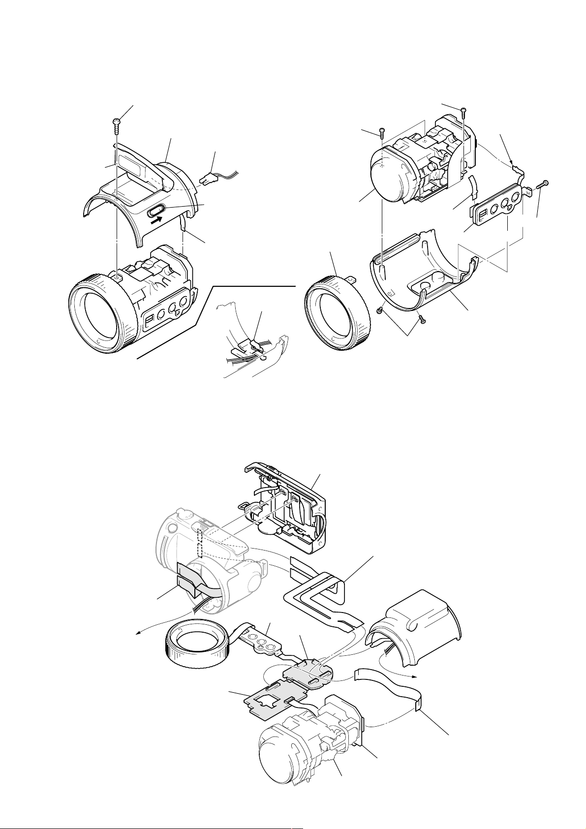
2-3. CABINET (LT) BLOCK 2-4. LENS BLOCK
Flash unit
(Note)
2 Screw (M1.7)
3 Cabinet (LT) block
7 Two screws
(M1.7)
5 Harness (MS-114)
(Flash unit (ST), 2P)
(Note)
8 Screw (M1.7)
2 Flexible board
(CN803)
1 Push the Release knob
4 FP-136 flexible board
(CN804)
Harness clamp
Cabinet (LT) block
(Bottom view)
Note: Clamp the cables after attaching the Harness
(MS-114). If clamped with the flash unit closed,
the flash unit cannot be opened. Be sure to
clamp the cable with the flash unit opened.
0 Lens block
6 Cabinet (MF)
assembly
3 Flexible board
(CN001)
4 Control switch
block (CF)
9 Cabinet (LB)
assembly
5 Two screws
(M1.7)
[SERVICE POSITION-1 (LENS BLOCK AREA: CD-283, PS-434, SY-62 BOARDS)]
Rear cabinet block
1 Screw (M1.7)
FP-37 flexible board
(Not used)
Harness (MS-114)
(to Cabinet (LT) block)
Cabinet (MF) assembly
Control switch block (CF)
PS-434 board
SY-62 board
2-3
Lens block
Extension cable (39, 39P 0.3 mm)
Parts No. : 1-678-657-11
(HI-73 board: CN701, 702)
(SY-62 board: CN801, 802)
Cabinet (LT) block
(Flash unit (ST))
Harness (MS-114)
(from Front cabinet block)
Extension cable (39P 0.3 mm)
Parts No. : J-6082-448-A
CD-283 board
(PS-434 board: CN602)
(CD-283 board: CN101)
Page 4

2-5. LCD PANEL BLOCK, CONTROL SWITCH BLOCK (FK)
8 Control switch block (FK)
Rear cabinet assembly
3 Two screws
(1.7 × 4)
4 Two screws (1.7)
2 Zoom switch
(RV001)
1 Screw (1.7 × 4)
6 Screw (M1.7)
9 Button (LCD bright)
0 Knob (LCD back light)
7 Two screws (M1.7)
5 LCD panel block
(Refer to 2-11. Crystal indication module)
[SERVICE POSITION-2 (REAR CABINET AREA: LCD PANEL BLOCK, CONTROL SWITCH
BLOCK (FK))]
Cold cathode fluorescent tube (ND901)
(with Inverter transformer unit)
Control switch block (FK)
FP-134 flexible board
(CN901)
Crystal indication module (LCD901)
SP901
Flexible board (control switch block (FK))
(CN705)
(with FP-134 flexible board)
Harness (speaker)
(CN252)
2-4
Page 5

2-6. HI-73, DD-148 BOARDS, BATTERY HOLDER BLOCK
1 FP-132 flexible board
(HI-73 board: CN707)
(DD-148 board: CN003)
5 Three screws
(1.7 × 4)
qa Two screws
(1.7 × 4)
8 Screw (M1.7)
0 Battery holder block
9 Screw
(M1.7)
qs DD-148 board
6 HI-73 board
2 FP-37 flexible board
(CN701, 702)
3 Harness (microphone)
(CN251)
7 Harness (MD-97)
(CN002)
4 Control switch block (PW)
(CN704)
2-7. UPPER CABINET BLOCK, FLASH UNIT (MC)
Note: When the flash unit (MC) charging failed, Page: D, Address: 67, Data: 04 are written.
After repair, be sure to write Page: D, Address: C7, Data: 00.
3 Two claws
4 Upper cabinet block
Groove
2 Harness (GN-52)
6 Claw
5 Harness (MS-114)
Groove
1 Screw (M1.7)
7 Flash unit (MC) (Note)
Edge
Edge
Flash unit (MC)
Details diagram on removal and attachment
of Control switch block (PW)
Upper cabinet block
Pin
Claw
Hole
Claw
Screw (1.7 × 4)
Control switch block (PW)
JK retainer assembly
Groove
Claw
Claw
Screw (1.7 × 4)
Note for installation of
Flash unit (MC)
Should be fit to the Front
cabinet groove.
2-5
Groove
Page 6

[SERVICE POSITION-3 (HI-73, DD-148 BOARDS)]
Control switch block (PW)
Front cabinet block
DD-148 board
FP-37 flexible board
(Not used)
HI-73 board
Rear cabinet block
Harness (HB-50)
(CN706)
Harness (speaker)
(CN252)
Zoom lens block
2-8. FRONT CABINET ASSEMBLY
4 Front cabinet assembly
Battery holder block
(to AC power adaptor)
Extension cable (39, 39P 0.3 mm)
Parts No. : 1-678-657-11
(HI-73 board: CN701, 702)
(SY-62 board: CN801, 802)
1 Lift up the Zoom lens block.
3 Screw (M2 × 4)
2 Screw (M2 × 4)
2-6
Page 7

2-9. REMOVAL AND ATTACHMENT OF FP-37 FLEXIBLE BOARD
Note: For folding new FP-37 flexible board, refer to “2-10. To fold the
new FP-37 flexible board” .
FP-37 flexible board
Harness (MS-114)
Harness (GN-52)
FP holder
FP-37 flexible board
(CN801)
When attaching, coil in the direction of
arrow A with two and a half revolutions.
(FP-37 flexible board )
A
Hook cover
Harness (GN-52)
FP-37 flexible board
(CN802)
Screw (M1.7)
Screw (M1.7)
Screw (M2 x 4)
Hook the claw of harness
Harness (MS-114)
Hinge cover
Harness (GN-52)
FP guard
2-10. TO FOLD THE NEW FP-37 FLEXIBLE BOARD
: Fold
Adhesive tape
: Fold
Adhesive tape
1-678-657-xx
FP-37
Adhesive tape
1-678-657-xx
FP-37
Adhesive tape
Note: For attaching new FP-37 flexible board, refer
to “2-9. Removal and attachment of FP-37
flexible board” .
2-7
Page 8

2-11. CRYSTAL INDICATION MODULE
Note for installation
Portion A and B
Portion C and D
8 Cold cathode fluorescent tube (ND901)
5 FP-134 flexible board
7 Screw (M1.7)
A
B
2 Crystal indication module (LCD901)
3 BL cushion
D
C
6 Flexible board
(Inverter transformer unit)
9 Inverter transformer unit
1 Flexible board
(FP-134 board)
4 Screw (M1.7)
2-12. FLASH UNIT (ST)
1 Screw
(M1.7 × 4)
7 Flash unit (ST)
5 Three claws
6 Cabinet (ST)
2 FP-136 flexible board
(Flash unit ST)
4 Claw
2-8
3 Push the Release knob
Page 9

2-13. CIRCUIT BOARDS LOCATION
FLASH UNIT (MC)
FLASH UNIT (ST)
DD-148
(DC/DC CONVERTER)
INVER TER TRANSFORMER UNIT
PS-434
(CAMERA DISPLAY, MEMORY, AUDIO AD/DA CONVERTER, LENS DRIVE)
CN-121
(CONNECTION)
HI-73
(LCD DRIVE, TIMING GENERATOR, VIDEO, USB I/F, AUDIO, HI CONTROL)
CD-283
(CCD IMAGER, CAMERA)
SY-62
(SH DSP, MEMORY)
2-14. FLEXIBLE BOARDS LOCATION
CONTROL SWITCH BLOCK (FK)
FP-136
CONTROL SWITCH BLOCK (PW)
FP-132
FP-36
CONTROL SWITCH BLOCK (CF)
MANUAL FOCUS BLOCK
2-9
E
FP-134
FP-37
LENS BLOCK
 Loading...