

Sony DS001AKA Datasheet
Description
The DS001AKA is a single-panel liquid crystal
optical engine for use in rear projectors, capable of
full-color displays without color filters (CF).
This engine provides a wide aspect ratio of 16:9,
such as those represented in HD.
The side-black function also allows an aspect ratio
of 4:3 in the NTSC/PAL mode. Up/down and/or right/
left inversion functions accommodate various mounting
methods.
Short projection distances are made possible
through the adoption of ultra-wide angle lenses. In
addition, a projection lens floating mechanism
delivers 30" to 60" projected images with minimal
image distortion.
A high intensity discharge (HID) lamp ensures high
luminance and low power consumption.
Features
• The number of active dots: 768,000
• Horizontal resolution: 600 TV lines
• NTSC/NTSC-WIDE/HD (band: 20MHz) mode selectable (PAL/PAL-WIDE mode also available through
conversion of scanned dot numbers by an external IC)
• Up/down and/or right/left inverse display function
• Side-black function
• 16:9 and 4:3 aspect-ratio switching function
• Full-color display with CF-less projection system
• High luminouce flux: normally-white 120 ANSIlm (typ.)
• Ultra-wide angle lenses for short projection distances (531mm/37", at 4.5% overscanning)
• Image distortion correction floating mechanism to support 30" to 60"
• Relative illumination: 70% or above
• Uses HID lamp (100W)
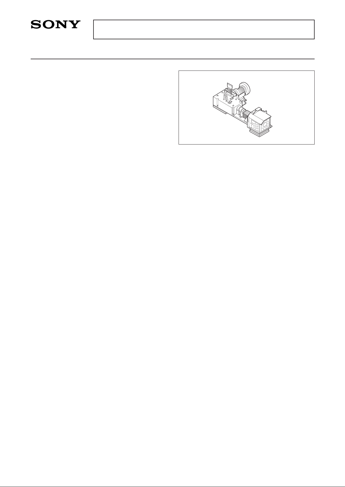
Engine Configuration
• HID lamp
• Lamp driver (DC 300V input)
• High-efficiency illumination system employing glass rods
• Separate RGB illumination systems using dichroic mirrors (DM)
• LCD panel mounting mechanism, adjustable along XYθ axes
• LCD panel (LCX011AM)
Dots
16:9 display: 1599.5 (H) × 480 (V) = 767,760 dots
4:3 display: 1199.5 (H) × 480 (V) = 575,760 dots
• Wide fixed focal length lenses for enlarged projection of LCD
• Silent fans for cooling
Applications
Liquid crystal rear projection TV/monitor
– 1 –
DS001AKA
E97422A94-PS
Single-Panel Liquid Crystal Optical Engine for Rear Projectors
Sony reserves the right to change products and specifications without prior notice. This information does not convey any license by
any implication or otherwise under any patents or other right. Application circuits shown, if any, are typical examples illustrating the
operation of the devices. Sony cannot assume responsibility for any problems arising out of the use of these circuits.
– 2 –
DS001AKA
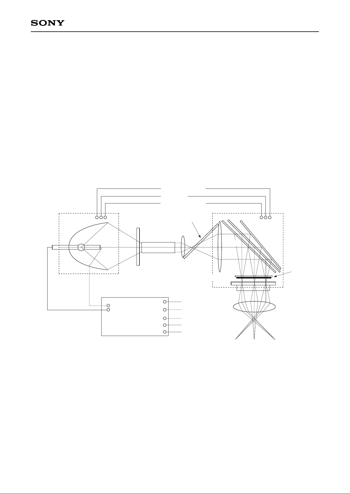
Explanation of Basic Operation
• Apply DC 300V to the lamp driver.
• Light emitted by the lamp is focused by an elliptical reflector on a glass rod integrator, and is rendered
homogeneous at the output end of the integrator.
• Light output from the integrator passes through a relay lens and collimator lens to become a collimated ray,
which is color-separated by a group of dichroic mirrors.
• The color-separated rays are focused on the respective RGB dots by microlenses mounted on the
LCX011AM, and distributed.
• After transmitting the panel, the light is enlarged and projected onto a screen by a projection lens.
For details of the LCD panel operation, please refer to the LCX011AM specifications.
Block Diagram
HID
Lamp
Glass Rod
Integrator
UV/IR Cut
Filter
Relay Lens
Pre-Polarizer
B-DM G-DM
Polarizer
LCD Panel
Lamp Driver
Positive (DC 300V)
Common
Start control input (SCI)
GND
Signal output
Connector 1
Connector 2
Fan 1
Fan 2
R-DM
Projection
Lens
Fan 1 Fan 2
Red: power supply
Red: GND
Red: sensor output
Collimator
– 3 –
DS001AKA
Pin Description and Operating Conditions
Ambient Temperature
Optical engine unit (excluding lamp driver)
• Operating temperature Topr 0 to +50 °C
• Storage temperature Tstg –20 to +60 °C
Lamp driver unit
• Operating temperature Topr –5 to +65 °C (under forced air cooling)
• Storage temperature Tstg –40 to +85 °C
Lamp Driver Unit
+5V
4.7kΩ
Signal output
(Flag output)
SCI
GND
1
2
3
Connector 2
Connector 1
1
3
To lamp
Pin Description
Operating Conditions
Connector 1
DC power supply input
Connector 2
SCI (start control input) and signal output
1
2
3
Connector
type
positive (DC 300V)
—
common
JST (Japan Solderless Terminal)
B 2P3-VH-B
start control input (SCI)
GND
signal output (flag output)
JST (Japan Solderless Terminal)
B 3B-PH-K
Input voltage
Power consumption
Circuit loss
Lamp output
Lamp startup peak voltage
Start control input (SCI)
Input voltage
Lamp extinguish
Lamp light
Signal output (flag output)
Output voltage
Lamp extinguish
Lamp light
Min.
220
105
—
95
—
—
3.5
—
3.5
Typ.
300
110
10
100
—
—
5.0
—
—
Max.
390
120
15
105
25
1.0
7.0
1.0
—
Unit
V
W
W
W
kV
V
V
V
V
Remarks
Input current < 1.0mA
Input current < 5.0mA
– 4 –
DS001AKA
DC Fan Unit (Fan 1, Fan 2)
DC fan
Sensor output (yellow)
I sink 5.0mA max
Vcc 28V max
Pin Description
Item
Red cable
Blue cable
Yellow cable
Connector type
Fan1, Fan2
power supply (positive)
GND
sensor output
When revolving: low
When restrained: high
Housing MLX5102-03
Pin MLX5103-TL
Remarks
rated 12V
restraint detection
(open collector output)
mfg. by Morex
Operating Conditions
Fan 1
Item
Supply voltage
Power consumption
Current consumption when open
Current consumption when restrained
Sensor output
Vcc
Vcc (sat)
I sink
Min.
10.5
—
—
—
—
—
—
Typ.
12.0
1.4
—
—
—
—
—
Max.
13.5
0.14
0.30
28
1.0
5.0
Unit
V
W
A
A
V
V
mA
Remarks
rated voltage
rated voltage
rated voltage
Fan 2
Item
Supply voltage
Power consumption
Current consumption when open
Current consumption when restrained
Sensor output
Vcc
Vcc (sat)
I sink
Min.
10.5
—
—
—
—
—
—
Typ.
12.0
2.0
—
—
—
—
—
Max.
13.5
0.20
0.45
28
1.0
5.0
Unit
V
W
A
A
V
V
mA
Remarks
rated voltage
rated voltage
rated voltage
For details of the LCD panel operating conditions and pin description, refer to the LCX011AM specifications.
 Loading...