

Sony DMX-R100 SUPPLEMENT

3-206-941-12 (1)
Digital A udio Mixer
SUPPLEMENT
Software Version 2.1
Software Version 2.2
Manual to be supplemented
DMX-R100 Operating Instructions (Part No. 3-868-264-13)
DMX-R100
2002 Sony Corporation


Table of Contents
How to Use This Supplement....................................................................4
What You Need to Use the Optional DMBK-R109 MADI Board .......4
Updating the DMX-R100 Software of the Console...................4
Compatibility of Titles ............................................................... 4
Updating the DMX-R100 Software ...........................................5
Inserting the DMBK-R109 into the Console ............................. 5
Addition and Changes in the New Version .............................................6
Menu Structure of the Version 2.1.............................................6
Changes on the Menu Bar..........................................................7
Changes in the COPY/LINK Window.......................................7
Changes in the AUDIO INPUT ROUTING Window ...............8
Changes in the AUDIO OUTPUT ROUTING Window .........10
Changes in the I/O STATUS Window.....................................12
CASCADE Window ................................................................13
How to Use the Optional DMBK-R109 MADI Board..........................16
Locations and Functions of Parts and Connectors of
the DMBK-R109......................................................................16
Using the Console Alone ......................................................... 18
Using the System in a Cascade Connection.............................19
Addition to Dialogues in the Window .................................................... 21
Addition and Changes in the Software Upgraded to Version 2.2 .......22
Overview of Version 2.2..........................................................22
Manual Group Function ........................................................... 22
Control Link Between Two Consoles......................................24
Insert REC Function.................................................................28
Automation Editor....................................................................29
Additions, Changes and Corrections in Other Functions.........29
Notes ........................................................................................ 30
Addition to Dialogues in the Window in the Software
Upgraded to Version 2.2 .........................................................31
Operation Manual Errata....................................................................... 32
Block Diagram ......................................................................................... 35
Commands Used for Machine Control..................................................37
MIDI Machine Control Commands (MIDI 1 to 16) ................37
Sony Serial Interface Protocol (REM 1 and 2) ........................37
3

How to Use This Supplement
The DMX-R100 software had been updated from
Version 2.0 to Version 2.1 to enable use of the
optional DMBK-R109 MADI board. Subsequently, it
was updated to Version 2.2 to improve the control link
between two DMX-R100s connected in cascade mode,
operation of the fader group and so on.
This supplement provides information to help update
the DMX-R100 software to Version 2.1 or later,
descriptions of changes/additions to the specifications
made in the DMX-R100 and information on the
function of the optional DMBK-R109 MADI board
and how to use it. also provided are the corrections to
the Operating Instructions (Part No. 3-868-264-13
(1)).
For conventional functions that will not be affected by the
software update, refer to the Operating Instructions (Part
No. 3-868-264-13 (1)).
What You Need to Use the Optional DMBK-R109
MADI Board
Updating the DMX-R100
Software of the Console
After you have updated the system to Version 2.0, you
can reinstall either Version 1.1x or Version 2.x at any
time.
You can use the optional DMBK-R109 MADI board
only with DMX-R100, Version 2.1 or later. Be sure to
confirm that the software version displayed when you
start the console is Version 2.1 or later before using the
DMBK-R109.
•If the version information displayed indicates Version
2.0, update the software using the APPLICATION
UPDATE 2.x disk, referring to “Updating the DMXR100 Software” on page 5.
•When the version you have is Version 1.x, it is
necessary to update the software to Version 2.0 first,
then to Version 2.1 because the system files of
Version 2.0 are different from those of Version 1.x.
To update the system from Version 1.0 to 2.0,
purchase the V2.0 update kit (not supplied) and
update the system to Version 2.0 using the SYSTEM
UPDATE 2.0 disk provided with the V2.0 update kit
first. Then, update the system to Version 2.1 using
the APPLICATION UPDATE 2.x disk supplied with
the DMBK-R109.
Contact with your nearest Sony dealer to purchase the
V2.0 Update Kit and the latest APPLICATION
UPDATE.
For detailed information on how to update the system to
Version 2.0, refer to “Updating the DMX-R100 Version” on
page 98 in the Operating Instructions for the DMX-R100
(Part No. 3-868-264-13 (1)).
Compatibility of Titles
•You can use a title saved using the Version 2.0
console with Version 2.1.
•You can use a title saved using the Version 2.1
console with Version 2.0. However, settings related
to the DMBK-R109 are ignored and input and output
connections to the DMBK-R109 are treated as NC
(NO CONNECTION). Also, the setting of MANUAL
GROUP of Version 2.2 is cleared.
•A title saved using the Version 1.x console is not
compatible with a title saved using the Version 2.x
console. If you try to load a title saved using Version
1.x from the flash memory to the Version 2.x
console, a title error occurs and the title saved using
Version 1.x is automatically lost.
•If you try to recall a title saved using Version 2.x
from the Version 1.x console, a title error occurs and
you cannot use that title. Also, if you try to load a
title saved using Version 2.x from the flash memory
to the Version 1.x console, a title error occurs and the
title saved using Version 2.x is automatically lost.
4
Updating the DMX-R100
Software
When you press “y,” the update programs are
decompressed, and the disk files are installed in
order, with the process showing on the screen.
1 Confirm that you have the update files,
“APPLICATION UPDATE 2.1x” on the DOSformatted floppy disk.
2 Connect a PS/2 keyboard (not supplied) to the
console and turn on the power of the console.
The start-up window opens.
3 Press the ESC key on the external keyboard a few
times until the dialogue “Loading now......”
appears in white on a blue screen.
When the console system enters the software
update mode, the dialogue “Will you update this
system? (y/n)” appears.
4 To execute the update, press “y” on the keyboard.
If you enter this mode by mistake, press “n.”
When you press “n,” the system starts as usual.
WARNING
Never press “y” without having prepared the
update floppy disk beforehand. If a DMX-R100
executes the update operations without the correct
update disk, the console software files may be
damaged and the console may not work properly.
When you press “y,” the message “Insert the
floppy disk and press any key.” appears.
When a DMX-R100 system has been updated, the
message “Update for XXXX completed. Remove
your floppy disk and press any key...” appears.
7 Remove the floppy disk and press the space bar on
the keyboard.
8 When the message “Stand-by....” appears, turn the
power of the console OFF once. Wait more than 10
seconds, then turn the power ON again.
The DMX-R100 will now run using Version 2.1x
of the software.
Note
After the DMX-R100 software has been updated, the
calibration data of the fader is reset to the default
settings. Thus, after finishing a software update,
calibrate the fader position.
For detailed information on how to calibrate the fader
position, refer to page 96 in the Operating Instructions.
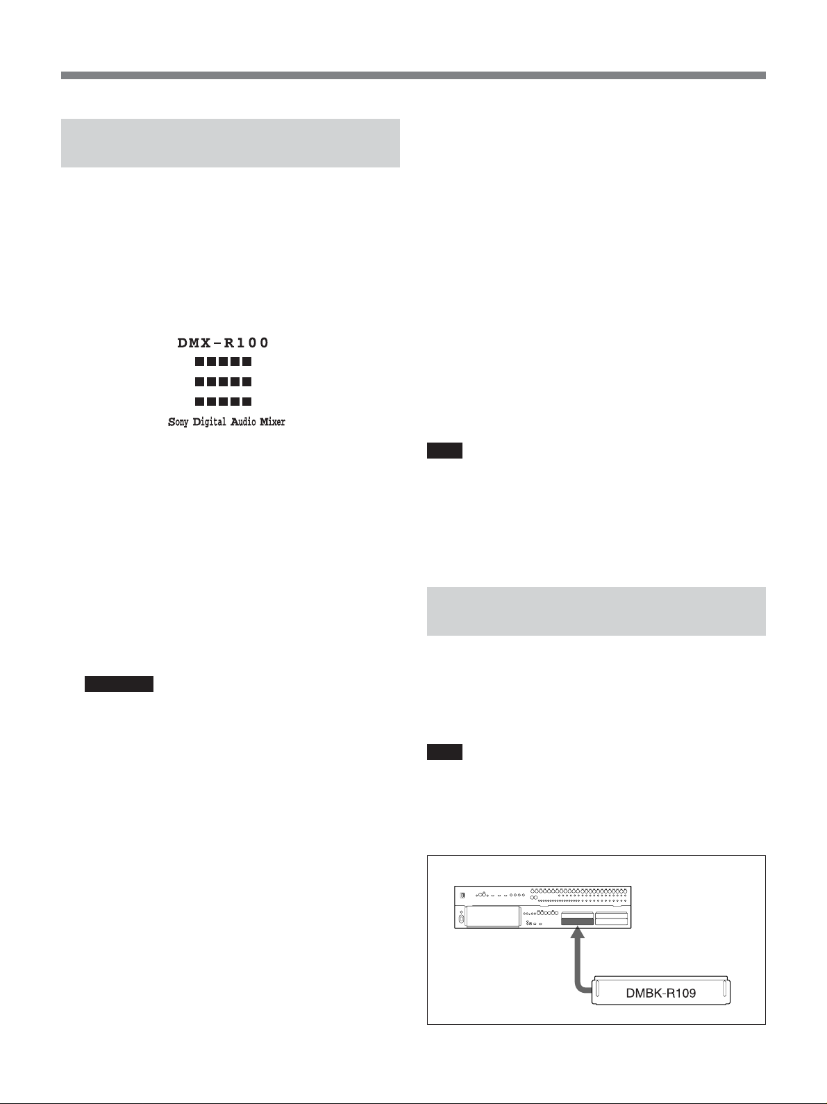
Inserting the DMBK-R109 into
the Console
Be sure to insert the optional DMBK-R109 MADI
board into SLOT 4 of the console.
Contact your nearest Sony dealer for assistance when
adding the board.
Note
Be sure to turn the power of the console off before
inserting an optional board into a slot.
Failing to do so results in the cause of console or
optional board malfunction.
5 Insert the “APPLICATION UPDATE 2.1x” disk
into the floppy disk drive on the console, and press
the space bar on the keyboard.
The specifics of the update and the “This updater is
...OK? (y/n)” message appear.
6 Confirm the information on the screen, then;
• press “y” on the keyboard, to start the update.
• if the screen shows incorrect information or
parameters, press “n” to cancel the update
operation.
DMX-R100
to SLOT 4
5

Addition and Changes in the New Version
Menu Structure of the Version 2.1
The window-based operating menus of Version 2.1
are organized in the following structure.
In Version 2.1, the COPY/LINK window, the AUDIO
INPUT ROUTING window, the AUDIO OUTPUT
ROUTING window and the I/O STATUS window
have been changed. The CASCADE window has been
added.
Menus for controlling and monitoring the mixer
CHANNEL menu
Unchanged from that of Version 2.0. Refer to pages 44 to 53.
AUDIO menu
AUDIO OVERVIEW window
AUDIO FADER window
AUDIO FADER/CUT GROUPING window
COPY/LINK window (page 7)
AUDIO INPUT ROUTING window (page 8)
AUDIO OUTPUT ROUTING window (page 10)
MONITOR window
OSC/TALKBACK window
For information on windows other than the COPY/LINK, AUDIO INPUT ROUTING and AUDIO
OUTPUT ROUTING windows, refer to pages 54 to 71.
For detailed information on each menu, refer to the
pages indicated in parentheses. For menus and
windows that are the same as those of Version 2.0,
refer to pages 38 to 97 in the Operating Instructions.
SNAPSHOT menu
Unchanged from that of Version 2.0. Refer to pages 72 and 73.
CUE menu
Unchanged from that of Version 2.0. Refer to pages 74 to 76.
AUTOMATION menu
Unchanged from that of Version 2.0. Refer to pages 77 to 79.
MACHINE CONTROL menu
Unchanged from that of Version 2.0. Refer to pages 80 to 82.
SYSTEM menu
TITLE MANAGER window
MIDI window
CASCADE window (page 13)
SYNC/TIME CODE window
I/O STATUS (input/output status) window (page 12)
MIS SETUP window
For information on windows other than the CASCADE and I/O STATUS windows, refer to pages 82 to
97.
6

Changes on the Menu Bar
The serial communication error display in Cascade
mode has been added to the menu bar. Other functions
When the console is used as a cascade master unit or a
cascade sub unit, SIO ERR is displayed in red on the
error display area if any error occurs in
communications using the PC port. Also, the
Changes in the COPY/LINK Window
The CH NAME button has been added to the function
buttons 5.
are the same as those of Version 2.0. Refer to pages 38
to 42 in the Operating Instructions.
Serial
communication
error display
CASCADE window has been added to the SYSTEM
button on the bottom menu bar when the DMBK-R109
is inserted.
Buttons 1 to 4 and buttons 6 to 8 are the same as
those of Version 2.0. For details on these buttons, refer
to pages 59 to 62 in the Operating Instructions.
1 STEREO LINKING
FUNCTIONS button
2 SURROUND LINKING
FUNCTIONS buttons
3 COPY tab
4 ZERO tab
5 Function buttons
6 SOURCE CHANNEL
and DESTINATION
CHANNEL boxes
CH NAME button
When this button is lit in green, you can copy the
channel name and also execute the “Zero” function.
RETURN button
7 SURROUND
LINK button
8 FADER COPY
button
CH NAME button
When the “Zero” function has been executed, the
corresponding channel name has been cleared.
7
Addition and Changes in the New Version
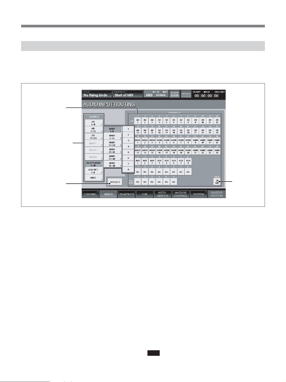
Changes in the AUDIO INPUT ROUTING Window
The functions of the source select buttons 2 and the
DEFAULT button 3 have been changed. The
1 Destination select
buttons
2 Source select buttons
3 DEFAULT button
functions of Destination select buttons 1 are the same
as those of Version 2.0. Refer to page 63 in the
Operating Instructions.
TB IN button
2 Source select buttons
When the window opens, the blocks of the input
sources are displayed. By touching the button of the
selected block, the source list of the selected block or
block list opens in the B direction.
The source list of each source block is as follows:
•Blocks for AD 1 to 8 to AD 17 to 24
Each block has the source list for 8 inputs.
•Blocks for SLOT 1 to SLOT 4
Each block has the source list for 8 channels.
When the DMBK-R109 is inserted into SLOT 4, 6
blocks are included in SLOT 4 and each block has
the source list for 8 channels.
•AUX RET block
This block has the source list for 8 channels.
•MISC block
Includes the lists for 2TR1-L, 2TR1-R, 2TR2-L,
2TR2-R, NC (NO CONNECTION) and TB MIC.
Touching NC opens NC8 (the adjacent 8 channels are
simultaneously set to NO CONNECTION).
The display of the block list buttons corresponding to
SLOT 1 to SLOT 4 depends on the board inserted.
•When a DMBK-R101 is inserted: SLOTxADC1 to 8
8
•When a DMBK-R102 is inserted: SLOTxDAC1 to 8
•When a DMBK-R103 is inserted: SLOTxDIO1 to 8
•When a DMBK-R104 is inserted: SLOTxSRC1 to 8
•When a DMBK-R105 is inserted:SLOTxINSERT1
to 8
•When a DMBK-R106 is inserted: SLOTxADAT1 to
8
•When a DMBK-R107 is inserted: SLOTxTDIF1 to 8
•When a DMBK-R109 is inserted: SLOT 4 MADI (A
DMBK-R109 can be inserted only into SLOT 4.)
When the SLOT 4 source select button is selected on
the cascade master console, the channels 1 to 24 of
MADI signals input to the sub console (in Fs = 44.1
kHz or 48 kHz and in 2Fs mode, the number of
channels is reduced to channels 1 to 12 of MADI
signals) and the busses of the sub console are
displayed and selectable.
3 DEFAULT button
Touch this button to open the dialog box and touch
OK to reset the settings of the input matrix to the
default shown in the table on the next page.
Note
When a DMBK-R109 is inserted into SLOT 4, the
input of the DMBK-R109 is not connected at the
default setting. When the DMBK-R109 is not inserted,
the settings of input matrix are reset to the values
shown in the table on page 101 in the Operating
Instructions.
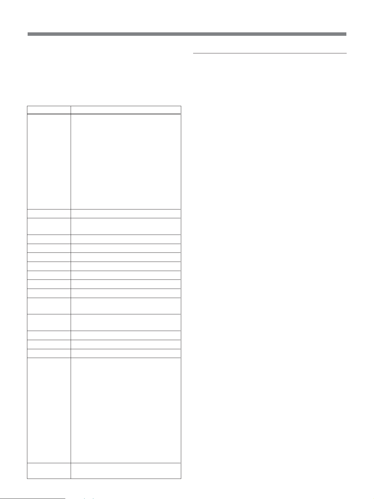
Default settings when the DMBK-R109 is inserted
Item
Input routing
Channel mode
Trim setting of
the input signal
Delay amount
Pan, MTR pan
Surround pan
Divergence
MTR assignment
PGM assignment
Equalizer
Dynamics
AUX send
Fader group
Cut
Fader
Output routing
Copy/Link
function
Setting
• AD 1 to 24 are connected to CH-1 to
CH-24.
•When a DMBK-R105 is inserted in the
option slot, each input channel of the
DMBK-R105 is connected to insertion
return 1 to 8.
•When the DMBK-R101/103/104/106/
107 is/are inserted, they are connected to
the channels starting from the lowest
slot number from CH-25 in order.
• The input to the DMBK-R109 inserted
into SLOT 4 is not connected.
Monaural
0 dB
0 Frame, COARSE: OFF
Control: Center, Button: ON
Front center
100 %
OFF
PGM L/R: ON
Control : Center, Button: OFF
Control :Center, Button: OFF,
EXPANDER: Access
Set all busses to monaural, OFF and
POST
Set all groups to GANG and OFF.
OFF
– Infinity
• PGM L/R busses are connected to the
PGM L/R connectors.
• AUX 1 to 8 busses are connected to the
AUX 1 to 8 connectors.
•When a DMBK-R105 is inserted in the
option slot, each output channel of the
DMBK-R105 is connected to insertion
send 1 to 8.
•When a DMBK-R102/103/106/107 is/
are inserted, MTRs 1 to 8 are connected.
• The output from the DMBK-R109
inserted into the SLOT 4 is not
connected.
All ON
Assigning the input source
1 Touch the source select button corresponding to
the desired block.
To select the sources by block, go to step 3.
To select a single source, touch the desired block
again.
The list of sources included in the selected block
opens.
2 Touch the desired source on the source list.
The list of the sources included in the block opens.
3 Touch the desired destination select button to
select the destination processing channel to which
the source signal is to be routed.
The source signal is routed to the proper
destination processing channel.
When you select the sources by block, sources are
automatically routed to the proper destination by
block.
Example: When you select ANALOG IN 1 to 8 as
a block, if you touch the CH-3 button, the source
signals of ANALOG IN 1 to 8 are routed to CH-3
to CH-10 respectively.
9
Addition and Changes in the New Version
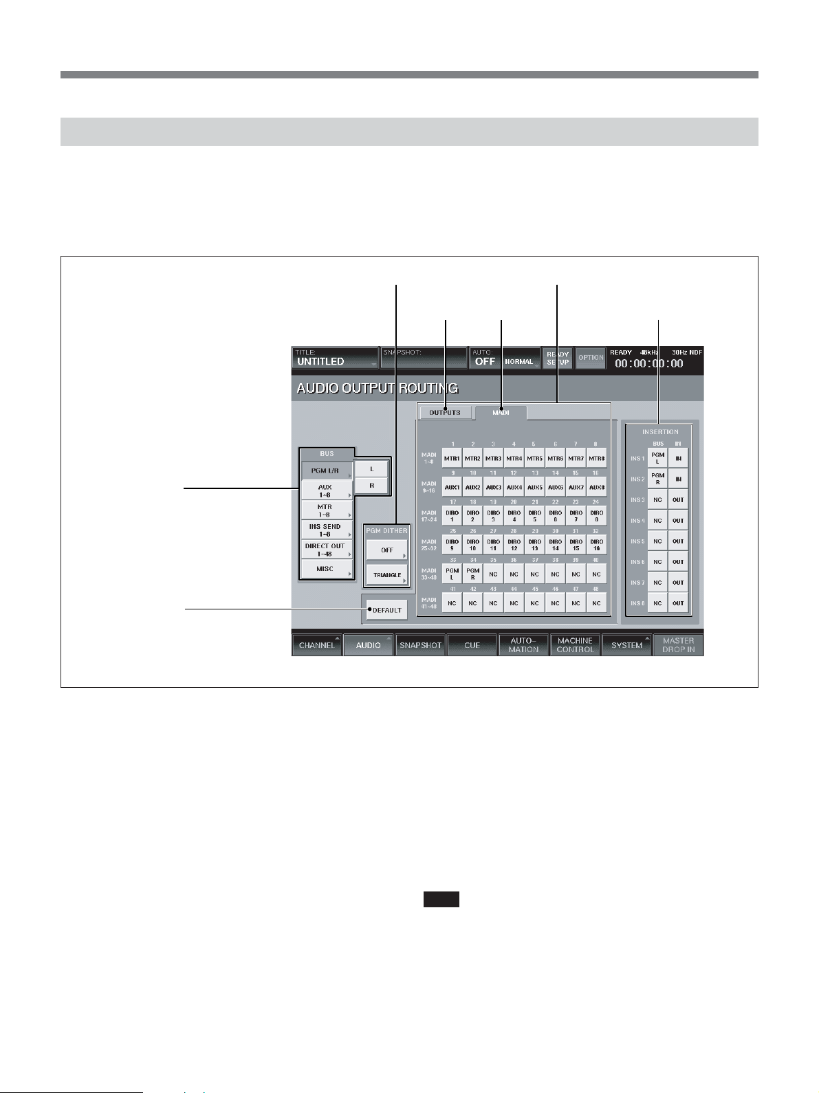
Changes in the AUDIO OUTPUT ROUTING Window
The functions of bus select buttons 1 and the
DEFAULT button 2 have been changed. A MADI tab
has been added to the output connector select buttons
4 when the DMBK-R109 is inserted.
3 PGM DITHER section 4 Output connector select buttons
1 Bus select button
The PGM DITHER section 3 and INSERTION
buttons 5 are the same as those of Version 2.0. For
detailed information on these buttons, refer to pages 65
and 66 in the Operating Instructions.
5 INSERTION buttonsOUTPUTS tab MADI tab
2 DEFAULT button
1 Bus select buttons
When the window opens, the blocks of the busses are
displayed. By touching the bus select button of the
desired bus, the bus list of the selected block opens in
the B direction.
The list of the block and its output bus list are as
follows:
•PGM L/R
L and R
•AUX
This block has 8 busses (AUX 1-8).
•MTR
This block has 8 busses (MTR 1-8).
•INS SEND
This block has 8 busses (INS SEND 1-8).
•DIRECT OUT 1-8 to 41-48
Each block has 8 outputs.
•MISC
This block contains NC (NO CONNECTION), CR
MONITOR 1 to 6 and ST MONITOR L/R.
Touching NC opens NC 8 (the adjacent 8 outputs are
simultaneously set to NO CONNECTION).
2 DEFAULT button
Touch this button to open the dialog box and touch
OK to reset the settings of the output matrix to the
defaults shown in the table on the previous page.
Note
When a DMBK-R109 is inserted into SLOT 4, the
output of the DMBK-R109 is not connected at the
default settings.
When a DMBK-R109 is not inserted, the settings of
output matrix are reset as shown in the table on page
101 in the Operating Instructions.
10

4 Output connector select buttons
Select the output connector to which the bus block (or
bus) displayed on the bus select button 1 is routed.
When a DMBK-R109 is not inserted into SLOT 4, the
OUTPUTS tab appears on the upper part of the screen
and one of SLOT 1 to 4, AUX SEND 1-8 or PGM
MONI OUT connectors is selectable.
Each of SLOT 1 to 4 has 8 output connectors.
When the DMBK-R109 is inserted into SLOT 4, the
MADI tab appears and the signals can be assigned to
the output channels of MADI.
On the sub console in Cascade mode, the MADI input
1 to 24 channels (in Fs = 44.1 kHz or 48 kHz) and
each bus are assigned to the CASCADE outputs in predetermined manner. Thus, even if you touch the MADI
tab on the sub console, you cannot change the bus
assignment.
(In 2Fs mode, the number of channels is reduced to
channels 1 to 12 of MADI signals.)
Assigning the bus
1 Touch the bus select button corresponding to the
desired bus.
To select the busses by block, go to step 3.
To select the single bus, touch that bus select
button again.
The list of busses included in the selected block
opens.
2 Touch the desired bus on the block list.
3 Touch the output connector button to route the bus
signal.
The bus signal(s) is routed to the output connector.
When you select the busses by block, busses are
automatically routed as a contiguous set of 8.
Example: When you select MTR 1 to 8 as a block,
if you touch 1 button of SLOT 1, the bus signals of
MTR 1 to 8 are routed to 1 to 8 connectors of
SLOT 1 respectively.
11
Addition and Changes in the New Version
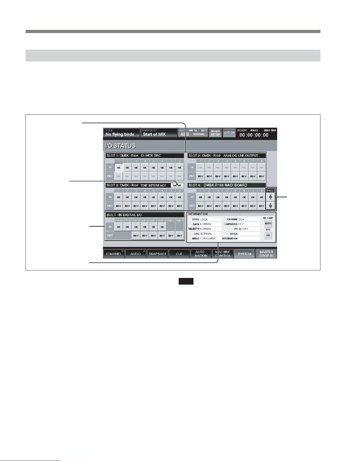
Changes in the I/O STATUS Window
Information displayed in the INFORMATION section
4 has been changed.
Also, page select buttons 5 have been added.
The functions of buttons 1 to 3 are the same as those
of Version 2.0. Refer to pages 91 to 93.
1 SLOT 1 to 4 section
2 DA 88 button
3 BUILT-IN DIGITAL I/O
section
4 INFORMATION section
4 INFORMATION section
When your system is not configured in a cascade
connection, the description of the INFORMATION
section is completely the same as the one on pages 92
and 93 in the Operating Instructions.
When your system is configured in the cascade
connection, the description after “VALIDITY” is
changed as follows:
On the console set as the cascade master unit, “- - - -”
is displayed even if the IN button of SLOT 4 is
selected.
Even if channels 1 to 24 of the MADI signal input to
the sub console are preemphasized, the master console
cannot detect this. Thus, confirm the setting on the I/O
STATUS window of the sub console, and then set the
DE EMP button manually as required. Only when the
DE EMP button is set to ON, will the audio signal be
deemphasized. However, since the bus signals output
from the cascade sub console are not preemphasized,
set the DE EMP button to OFF or AUTO for the
channel corresponding to the bus.
5 Page select
buttons
Note
There are some AES/EBU or MADI devices which do
not add the correct channel status to their digital audio
output signals. When the console inputs those signals,
errors occur on the descriptions after VALIDITY and
!xxx is displayed on the IN buttons of each slot. This is
not a malfunctions. (xxx indicates the abbreviation of
an error item.)
Use the signals as they are, after checking that there are
no audible problems with the input audio signals.
5 Page select buttons
When a DMBK-R109 is inserted into SLOT 4, the
page select buttons are displayed at the right side of the
screen. Set these buttons as required.
12
 Loading...