


DIGITAL PORTABLE MIXER
DMX-P01
SERVICE MANUAL
1st Edition
! WARNING
This manual is intended for qualified service personnel only.
To reduce the risk of electric shock, fire or injury, do not perform any servicing other than that
contained in the operating instructions unless you are qualified to do so. Refer all servicing to
qualified service personnel.
! WARNUNG
Die Anleitung ist nur für qualifiziertes Fachpersonal bestimmt.
Alle Wartungsarbeiten dürfen nur von qualifiziertem Fachpersonal ausgeführt werden. Um die
Gefahr eines elektrischen Schlages, Feuergefahr und Verletzungen zu vermeiden, sind bei
Wartungsarbeiten strikt die Angaben in der Anleitung zu befolgen. Andere als die angegeben
Wartungsarbeiten dürfen nur von Personen ausgeführt werden, die eine spezielle Befähigung
dazu besitzen.
! AVERTISSEMENT
Ce manual est destiné uniquement aux personnes compétentes en charge de l’entretien. Afin
de réduire les risques de décharge électrique, d’incendie ou de blessure n’effectuer que les
réparations indiquées dans le mode d’emploi à moins d’être qualifié pour en effectuer d’autres.
Pour toute réparation faire appel à une personne compétente uniquement.
DMX-P01

Table of Contents
Manual Structure
Preface ....................................................................................................................... 3
Purpose of this manual .............................................................................................. 3
Relative manual ......................................................................................................... 3
Contents .....................................................................................................................4
1. Service Overview
1-1. Installation...................................................................................................1-1
1-1-1. Operating Environment .............................................................. 1-1
1-1-2. Specifications .............................................................................1-1
1-1-3. Power Supply ............................................................................. 1-1
1-1-4. Dimensions.................................................................................1-2
1-1-5. Connecting Cables / Connectors ................................................1-3
1-1-6. Input / Output Signals of Connectors .........................................1-4
1-1-7. Inside Switch / Jumper Pin Setting ............................................1-6
1-2. Locations of Main Parts ..............................................................................1-6
1-3. Panel Removal ............................................................................................1-7
1-3-1. Case (Top) / Case (Bottom) Removal ........................................ 1-7
1-3-2. Front Panel Removal ..................................................................1-7
1-4. Note on Servicing........................................................................................1-8
1-5. Note on Holder SP (Battery Slot) Replacement..........................................1-8
1-6. Note on MAIN Board Replacement............................................................1-9
1-7. Change of Output Level .............................................................................. 1-9
1-8. Modification to 12V-T POWER ...............................................................1-10
1-9. Check Mode ..............................................................................................1-11
1-10. Note on LCD Replacement .......................................................................1-15
1-11. Note on Battery Compartment Frame Replacement .................................1-15
DMX-P01
2. Spare Parts
2-1. Notes on Repair Parts..................................................................................2-1
2-2. Exploded Views ..........................................................................................2-2
2-3. Electrical Parts List .....................................................................................2-6
2-4. Supplied Accessories ................................................................................2-18
3. Semiconductor Pin Assignments
1

4. Block Diagram
Circuit Description ...................................................................................... 4-1
Overall.........................................................................................................4-2
5. Board Layouts
MAIN ..........................................................................................................5-2
INPUT ......................................................................................................... 5-4
SW...............................................................................................................5-4
VOL.............................................................................................................5-4
LCD.............................................................................................................5-5
MASTER.....................................................................................................5-5
FUNC ..........................................................................................................5-5
HP-VOL ......................................................................................................5-5
AES .............................................................................................................5-5
SW2.............................................................................................................5-5
OUTPUT ..................................................................................................... 5-5
6. Schematic Diagrams
MAIN ..........................................................................................................6-2
INPUT ....................................................................................................... 6-10
SW.............................................................................................................6-10
VOL...........................................................................................................6-10
LCD...........................................................................................................6-11
FUNC ........................................................................................................6-11
MASTER...................................................................................................6-11
HP-VOL ....................................................................................................6-11
SW2...........................................................................................................6-12
AES ...........................................................................................................6-12
OUTPUT ................................................................................................... 6-12
Frame Wiring ............................................................................................ 6-13
2
DMX-P01

Preface
Purpose of this manual
Relative manual
Manual Structure
DMX-P01 is a portable digital mixer designed for Professional electric news
gathering (ENG) and electronic field production (EFP). DMX-P01 makes it ideal for
use with digital video and audio recording media such as a camcorder and microphones, and so on.
This manual is the service manual for Portable Digital Mixer DMX-P01.
This manual is intended for use by trained system and service engineers, and
provides the installation and notes on servicing, and so on. And also, this manual
describes items that premise the service based on the component parts such as parts
list, semiconductor pin assignments, block diagram, board layouts, and schematic
diagrams.
..
. Operating Instructions (Printed Manual) (Supplied with this unit)
..
Part number: 2-347-769-0X
..
. Operating Instructions (CD-ROM) (Supplied with this unit)
..
Part number: 2-347-770-0X
..
. “Semiconductor Pin Assignments” CD-ROM (Available on request)
..
This “Semiconductor Pin Assignments” CD-ROM allows you to search for
semiconductor used in this unit.
Semiconductors that cannot be searched for on this CD-ROM are listed in section
3 of this manual. Section 3 contains a complete list of all semiconductors used for
this unit and their ID Nos., and thus should be used together with the CD-ROM.
Part number: 9-968-546-XX
DMX-P01
3

Contents
Section 1 Service Overview
Describes the information on installing this unit, and the fundamental knowledge
that is required to service (the locations of main parts, removal of cabinet, the
procedure to change the output level, explanation of the check mode, notes, etc.)
Section 2 Spare Parts
Describes the exploded views, the mechanical parts list, and the electrical parts list.
Section 3 Semiconductor Pin Assignments
This section contains information on semiconductors used for this unit.
It includes a complete list of the semiconductors and their ID Nos. for retrieving
information on “Semiconductor Pin Assignments” CD-ROM, which is available
separately.
Refer to this section together with the “Semiconductor Pin Assignments” CD-ROM.
Information on the semiconductors not contained in the CD-ROM at the time of
issue this manual, is given in this section as well.
Section 4 Block Diagram
Describes the block diagram and the circuit description.
Section 5 Board Layouts
Describes the board layouts for this unit.
Section 6 Schematic Diagrams
Describes the schematic diagrams for this unit.
4
DMX-P01

Section 1
Service Overview
1-1. Installation
1-1-1. Operating Environment
Operating temperature: 0 dC to 45 dC (+32 dF to +113 dF)
Storage temperature:
Mass: Approx. 2.2 kg (4 lb 14 oz)
1-1-2. Specifications
Audio Characteristics
Frequency response: 20 Hz to 20 kHz, 0.5/_1 dB
Noise level (E.I.N): _130 dBu or less
T.H.D: 0.05% or less
Maximum output level: +24 dBu, load impedance 10 k Z
Crosstalk: _90 dB or less (at 1 kHz)
Continuous Operation Time of Internal Battery
Specification
5 hours or more (under the following conditions)
Conditions
Input: CH-1 INPUT
LINE/MIC/MIC +48V switch: MIC
Input gain control: _70 dB (fully clockwise)
CH-1 Input level control: >_∞ (not fully counter-
CH-2 to 4 Input level controls: _∞ (fully counterclock-
Output: ANALOG OUTPUT L
Output LEVEL switch: +4 dBu
HEADPHONES: Output 3 mW, 32 Z load
LCD LIGHT switch: OFF
SAMPLING RATE switch: 48kHz
Environment temperature: Room temperature
Batteries to be used: 8 LR6/AA-size Sony
_20 dC to 60 dC (_4 dF to +140 dF)
(at a 48-kHz sampling frequency)
20 Hz to 40 kHz, 0.5/_3 dB
(at a 96-kHz sampling frequency)
(A-weighted, mic input, 150 Z
terminated, typical)
(at 1 kHz, 4 dBu)
_70 dBu, 1 kHz sine
wave
clockwise)
wise)
+4 dBu, 600 Z load
(Approx. 25 dC)
alkaline batteries
1-1-3. Power Supply
Power requirements:
DC +10 V to +15 V (at the external power supply
from the DC IN 10-15V connector)
Maximum power consumption:
1400 mA or less (at the external power supply from
the DC IN 10-15V connector)
The unit can be powered in the following ways:
. Internal batteries
Eight LR6 (size AA) alkaline batteries can be accommodated in the battery compartment.
. External battery
A lithium ion battery or nickel metal hydride battery
which is connected to the DC IN 10-15V connector on
the right panel. The unit is equipped with two types of
DC IN 10-15V connector: an XLR 4-pin and a DC jack
type connector. Select either one depending on the
external battery you are using.
m
. Do not connect external batteries to both XLR 4-pin
type connector and the DC jack at the same time. Be
sure to connect the external battery to either one.
. Do not connect the external battery other than the BP-
90 type battery to the DC jack, because the polarity of
the DC jack is different.
Power Supply for Check and Repair
Perform the check and repair by supplying DC +10 to
+15 V from the DC regulated power supply capable of 3 A
or more output to the DC IN 10-15V connector.
n
For the names and functions of connectors and switches,
refer to Operating Instructions.
DMX-P01
1-1
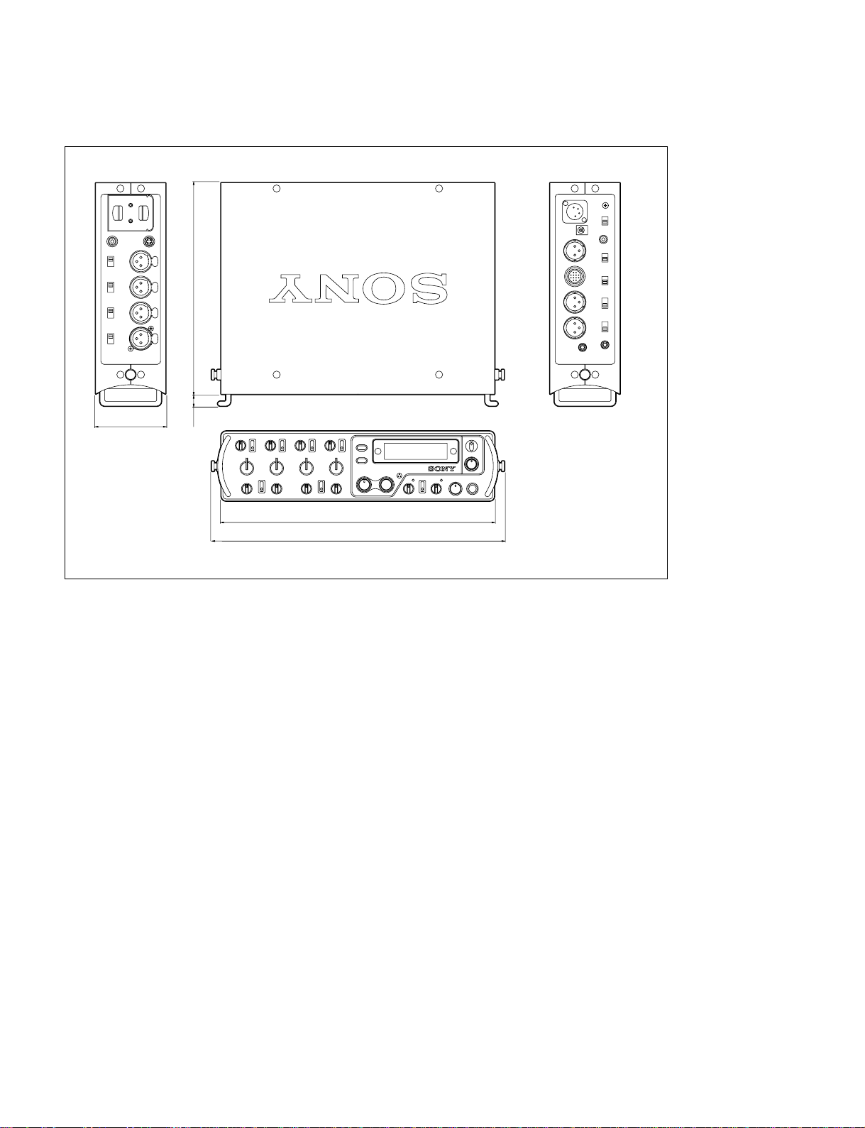
1-1-4. Dimensions
20612
68
266
285
Unit : mm
1-2
DMX-P01

1-1-5. Connecting Cables / Connectors
When connecting a cable with a connector at installation or service, use the following connectors and
cables, or equivalents:
Left Panel
Panel Indication Name
INPUT: CH-1, 2, 3, 4 XLR 3P, female XLR 3P, male 1-508-084-11
CASCADE IN PHONO jack PHONO plug —
DC OUT 200mA MAX 4P, female 4P, male 1-566-425-11
Corresponding connector / cable
Name Sony Part No.
Right Panel
Panel Indication Name
PHONES 3.5 mm TRS jack 3.5 mm TRS plug —
ANALOG OUTPUT: TAPE OUT 3.5 mm TRS jack 3.5 mm TRS plug —
L, R XLR 3P, male XLR 3P, female 1-508-083-11
CAMERA Round 12P, female Round 12P, male 1-817-336-11
DIGITAL OUTPUT: AES/EBU XLR 3P,male Connecting cable BCD-3C/10C/30C Option
COAXIAL PHONO jack PHONO plug —
DC IN 10-15V XLR 4P, male XLR 4P, male 1-508-362-00
DC jack DC plug —
Corresponding connector / cable
Name Sony Part No.
(Supplied one with this unit)
(3 m/10 m/30 m)
Front Panel
Corresponding connector / cable
Panel Indication Name
Name Sony Part No.
PHONES 3P ø6.3 TRS jack 3P ø6.3 TRS plug —
DMX-P01
1-3
1-1-6. Input / Output Signals of Connectors
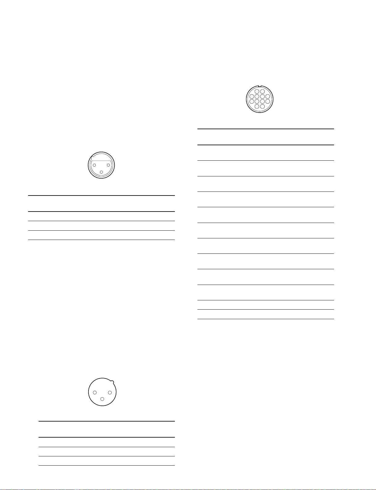
INPUT: CH-1, 2, 3 and 4 (XLR 3-pin, female): Left Panel
Analog audio signal input
At the MIC setting:
Reference input level: _70 to _30 dBu, 2.2 kZ, balance
Maximum input level: _50 to _10 dBu, 2.2 kZ, balance
At the MIC +48V setting:
External power output of DC +48 V
At the LINE setting:
Reference input level: _30 to +10 dBu, 10 kZ, balance
Maximum input level:_10 to +30 dBu, 10 kZ, balance
132
(External view)
Pin Signal Description
No. Name
1 GND GND of the analog audio signal input
2 HOT HOT of the analog audio signal input
3 COLD COLD of the analog audio signal input
CASCADE IN (PHONO jack): Left Panel
24-bit digital audio signal input in IEC60958 (S/P DIF)
format
Sampling frequency: 48 kHz or 96 kHz
Input impedance: 75 Z
ANALOG OUTPUT: Right Panel
CAMERA (12-pin, female)
Analog audio signal input / output
Reference input level: 0 dBu
Reference output level: +4/_20/_60 dBu
AB
DEHC
GJFK
LM
(External view)
Pin Signal Description
A L HOT HOT of the L output of the master audio
B L COLD COLD of the L output of the master audio
C R HOT HOT of the R output of the master audio
D R COLD COLD of the R output of the master
E L HOT HOT of the L input of the camera return
F L COLD COLD of the L input of the camera return
G R HOT HOT of the R input of the camera return
H R COLD COLD of the R input of the camera return
J GND GND of the output of the master audio
K GND GND of the input of the master audio
L NC No connection
M NC No connection
No. Name
signal
signal
signal
audio signal
audio signal
audio signal
audio signal
audio signal
signal
signal
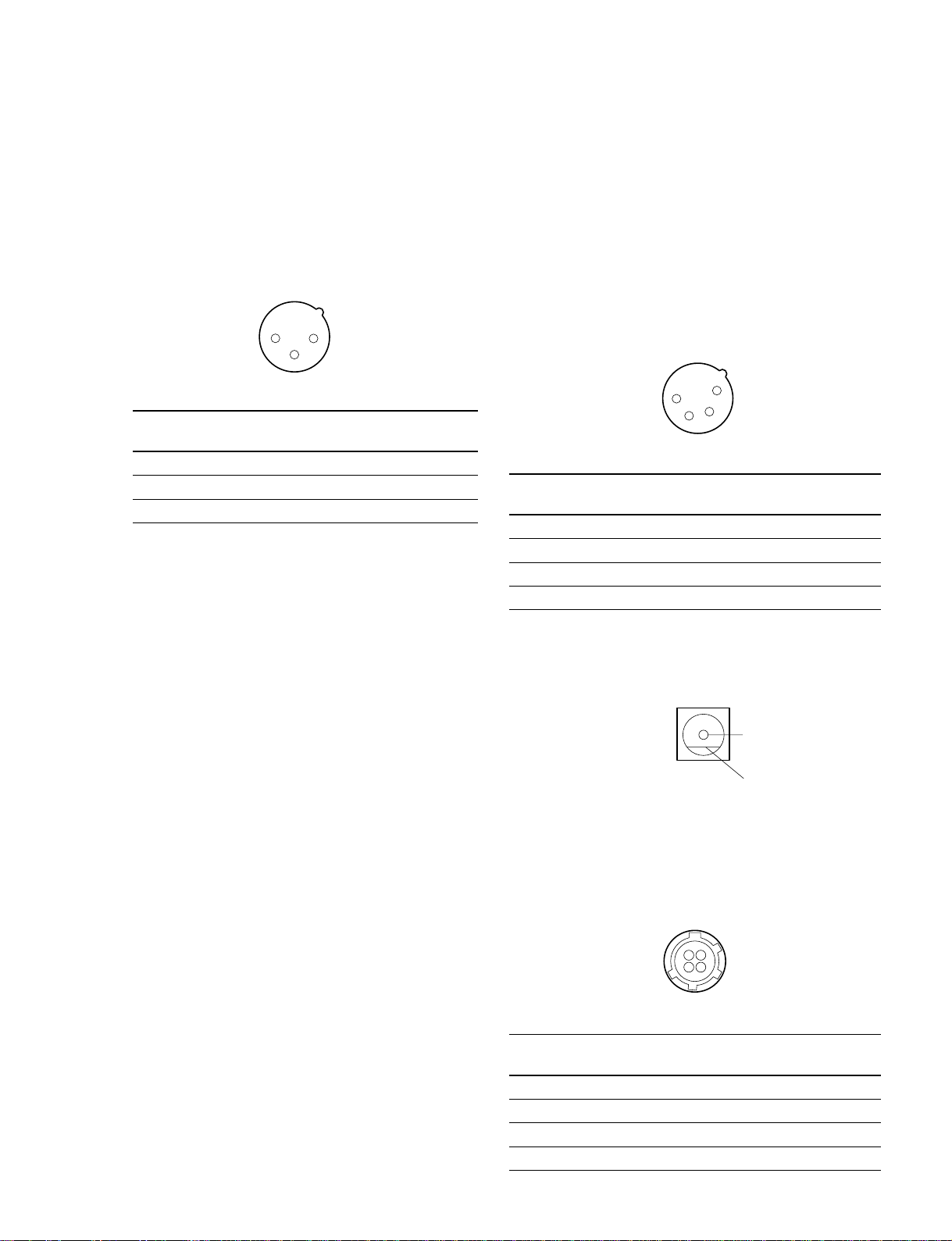
L and R (XLR 3-pin, male)
Analog audio signal output
Load impedance: 600 Z or more
Reference output level: +4/_20/_60 dBu
Maximum output level: +24 dBu (at +4dBu output
setting)
12
3
(External view)
Pin Signal Description
No. Name
1 GND GND of the analog audio signal output
2 HOT HOT of the analog audio signal output
3 COLD COLD of the analog audio signal output
1-4
TAPE OUT (3.5 mm TRS Jack)
Analog audio signal output
Load impedance: 10 kZ or more, unbalance
Reference output level: _10 dBu
Maximum output level: +10 dBu
DMX-P01
DIGITAL OUTPUT: Right Panel
AES/EBU (XLR 3-pin, male)
24-bit digital audio signal output in AES/EBU (AES3-
1992) format
Sampling frequency: 48 kHz or 96 kHz (Depends on
SAMPLING RATE switch)
Load impedance: 110 Z
PHONES (3.5 mm TRS jack): Right Panel
PHONES (3-pin ø6.3 TRS jack): Front Panel
Analog audio signal output
The output signal depends on the Headphones monitor
mode switch on the front panel.
Load impedance: 32 Z or more
300 mW or more (at the load of 32 Z)
12
3
(External view)
Pin Signal Description
No. Name
1 GND GND of the digital audio signal output
2 HOT HOT of the digital audio signal output
3 COLD COLD of the digital audio signal output
COAXIAL (PHONO jack)
24-bit digital audio signal output in IEC60958 (S/P
DIF) format
Sampling frequency: 48 kHz or 96 kHz (Depends on
SAMPLING RATE switch)
Load impedance: 75 Z
DC IN 10-15V (XLR 4-pin, male): Right Panel
Input voltage: DC +10 to +15 V
4
1
3
2
(External view)
Pin Signal Description
No. Name
1 GND GND of the external DC power input
2 NC No connection
3 NC No connection
4 +10-15V External DC power input
DC IN 10-15V (DC jack): Right Panel
Input voltage: DC +10 to +15 V
_
DMX-P01
(External view)
+
DC OUT (4-pin, female): Left Panel
Output voltage: DC +10 to +15 V
(Depends on DC IN 10-15V.)
4
1
2
3
(External view)
Pin Signal Description
No. Name
1 GND GND of the DC output
2 NC No connection
3 NC No connection
4 +10-15V DC output
1-5

1-1-7. Inside Switch / Jumper Pin Setting
MAIN Board
S601
S602
TEST
UPDATE
TP602
HEATER TEST
S601: UPDATE Switch
This switch is to write software into the microcomputer.
When you turn on the power of this unit while pressing this
switch, the mode becomes the writing mode of the software.
S602: TEST Switch
When you turn on the power of this unit while pressing this
switch, the mode turns into the check mode.
For details on the check mode, refer to Section 1-8.
TP602: HEATER TEST Pin
This is for the check of the LCD heater operation on the
LCD board.
When this pin is short-circuited, the heater activates to
allow you to check the heater operation as follows:
. Check the change of the value of CHECK MODE: No.
15: LCD TEMP. When the heater activates, the value
increases in several minutes.
For the check mode, refer to Section 1-8.
. Check the change of the current value of external power
source. When the heater activates, the current increases
by 160 - 240 mA.
n
The heater is activated only with the external power
supply (DC IN 10-15V connector). When the power is
supplied from the internal batteries, the heater is not
activated.
1-2. Locations of Main Parts
MAIN board
Battery
compartment
INPUT board
VOL board
1-6
SW2 board
AES board
OUTPUT board
HP-VOL board
MASTER board
LCD board
FUNC board
SW board
DMX-P01
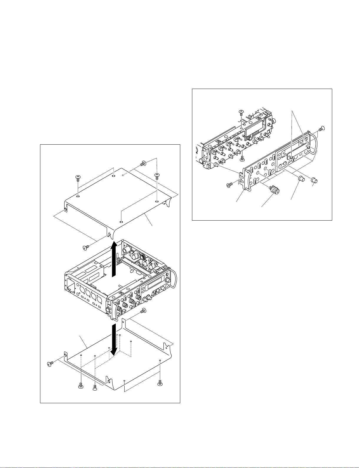
1-3. Panel Removal
Special screws(M2.6)
(with stopper)
K2.6 x 4
K2.6 x 4
Front panel
Knob (large)
Knob (1) assembly
Knob (0)
assembly
Step screw
Step screw
1-3-2. Front Panel Removal
1-3-1. Case (Top) / Case (Bottom) Removal
Remove the Case (Top) and the Case (Bottom) as shown in
the figure.
n
Before removing the Case (Bottom), be sure to turn off the
power.
When you turn on the power after the Case (Bottom)
removal, refer to Section 1-4.
Step screws
Step screws
Case (top)
1. Remove the Case (Top) and the Case (Bottom). (Refer
to Section 1-3-1.)
2. Remove the Front Panel as shown in the figure.
Step screws
Step screws
DMX-P01
Step screws
Case (bottom)
K2.6 x 4
Step screws
Step screws
1-7
1-4. Note on Servicing
Never turn on the power while the Case (Bottom) is
removed.
When the Case (Bottom) is removed for the check of the
MAIN board (B side), be sure to follow the following
procedures:
n
Ignoring the following procedures may cause a trouble,
because the GND for the board is not established.
1. Turn off the power, and remove the Case (bottom).
2. Solder the B-side lands of the EP101 and EP401 on the
MAIN board with a wire of AWG18 or more.
3. Turn on the power, and perform the check.
4. After the check, turn off the power and remove the
wire that was soldered in step 1.
5. Install the Case (Bottom).
Solder a wire thicker than AWG18.
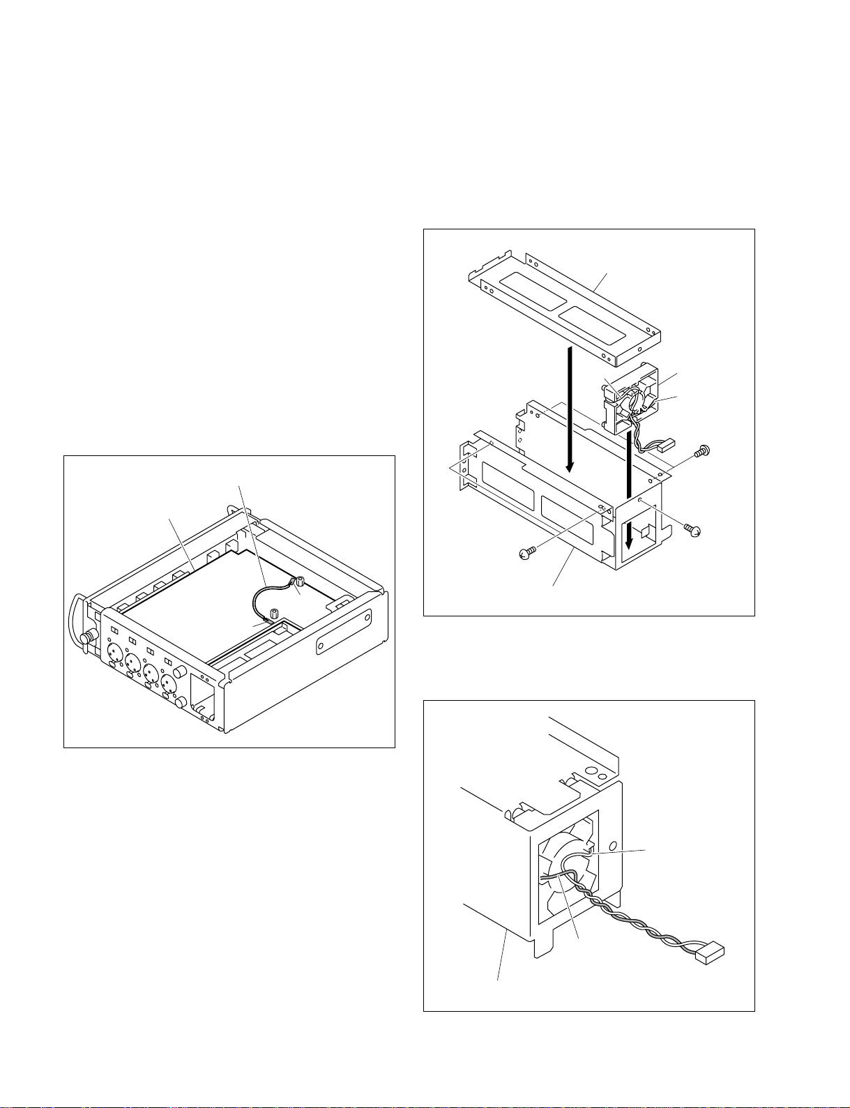
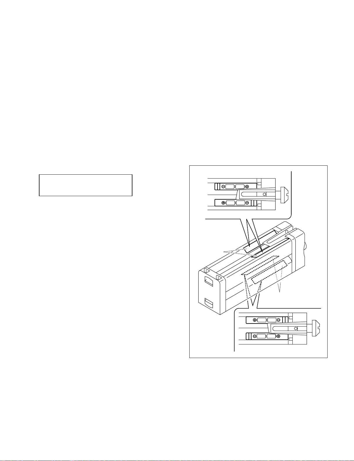
1-5. Note on Holder SP (Battery Slot)
Replacement
1. When the Holder SP is installed in the battery slot,
place the Holder SP confirming the positions of the
lead wires (Red and White) as shown in the figure.
Frame guide (L)
White
Holder SP
Red
BVTT
2.6 x 5
MAIN board (B side)
EP401
EP101
BVTT
2.6 x 5
BVTT
2.6 x 5
Frame guide (R)
2. After installing the battery slot (Frame Guide) onto the
unit, confirm that the lead wires (Red and White) of
the Holder SP are as shown in the figure.
White
1-8
Red
Frame guide (R)
DMX-P01

1-6. Note on MAIN Board Replacement
When the MAIN board is replaced with new one, the software version written in the built-in memory of
IC609 (system-control microcomputer) on the MAIN board may be different from the latest one due to
the bug fix.
After replacing the MAIN board, be sure to confirm that the software is the latest version referring to
technical memos. (For the way of version confirmation, refer to Section 1-9.) When a relevant technical
memo is not found, the latest software is Ver 1.00.
If the software version of the replaced MAIN board is not the latest one, write the latest software.
For the way to write software, refer to the technical memo.
1-7. Change of Output Level
By the factory setting, the reference output levels for ANALOG OUTPUT L and R are set to +4 dBu at
the LEVEL switch of +4.
To change the reference output levels to +6, 0, or _3 dBu, change the following values to the corresponding values.
n
By this setting change, the output level also changes at the LEVEL switch is in at _60 and _20. The
reference output level for TAPE OUT is not changed (_10 dBu).
Value Change List
Ref. No. Output Level
(MAIN board)
R203, 206, 226, 229 15 k 18 kZ 10 kZ 6.8 kZ
R323, 324, 325, 326 120 kZ 220 kZ 47 kZ 47 kZ
R248, 249 12 kZ 15 kZ 12 kZ 12 kZ
R250, 251 4.7 kZ 4.7 kZ 12 kZ 12 kZ
R253, 255 100 kZ 100 kZ 3.3 kZ 3.3 kZ
R327, 328 not mounted not mounted 1 kZ not mounted
C204, 205, 220, 221 150 pF 120 pF 220 pF 270 pF
++
+4 dB
++
(Factory Setting)
(1-218-875-11) (1-218-877-11) (1-218-871-11) (1-218-867-11)
(1-218-897-11) (1-218-903-11) (1-218-887-11) (1-218-887-11)
(1-216-834-11) (1-218-875-11) (1-218-873-11) (1-218-873-11)
(1-216-829-11) (1-218863-11) (1-218-873-11) (1-218-873-11)
(1-216-845-11) (1-218-895-11) (1-218-859-11) (1-218-859-11)
(1-164-217-11) (1-162-928-11) (1-162-960-11) (1-164-388-11)
++
+6 dBu 0 dBu
++
(1-218-847-11)
__
_3 dBu
__
DMX-P01
1-9
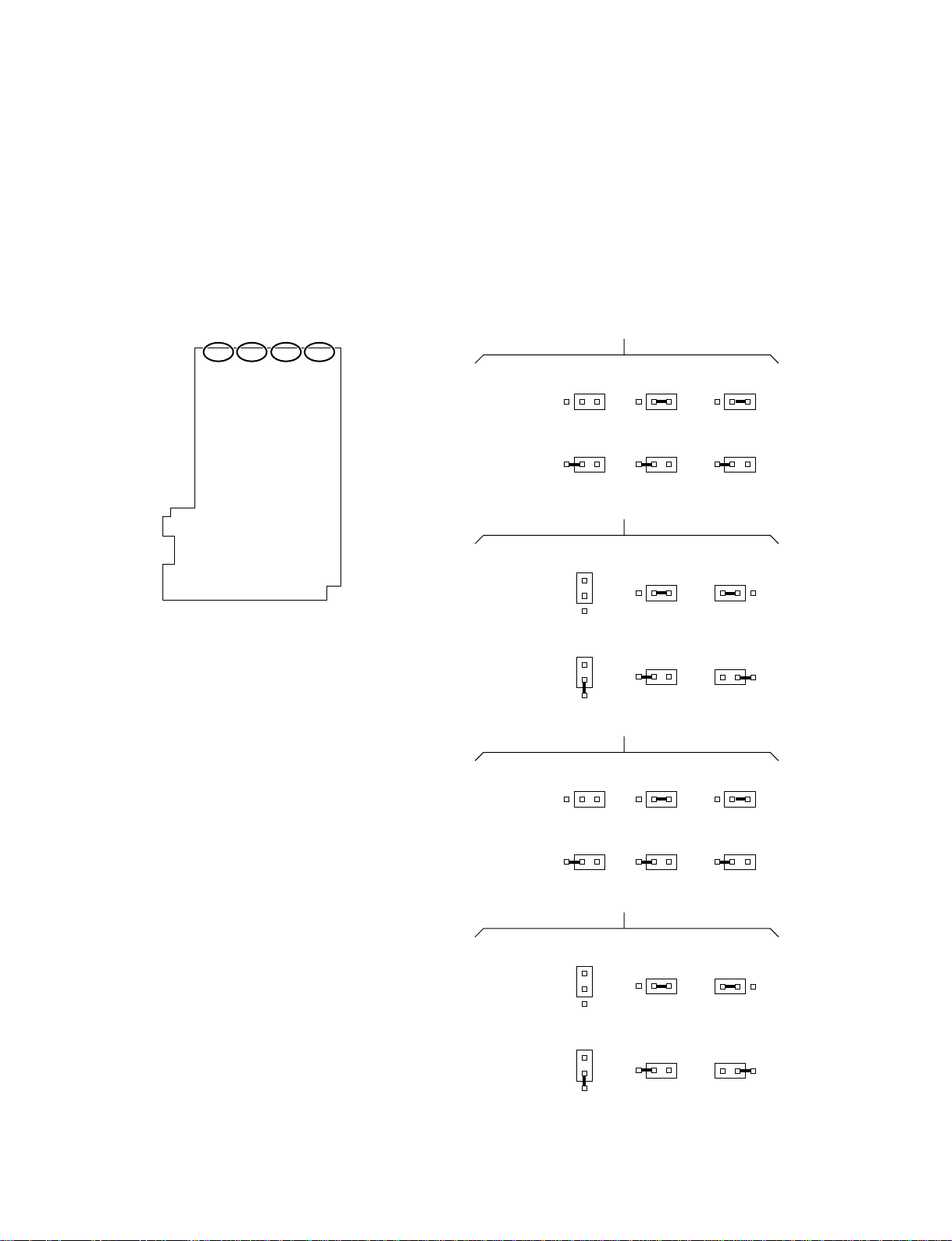
1-8. Modification to 12V-T POWER
Following is the method to modify the power supply each
input channel from 48V PHANTOM POWER to 12V-T
(A-B) POWER.
Change the short-circuiting by solder to +12V side that is
out of a white box as illustrated. Every input channel has
three places to be modified.
CH-1 CH-2 CH-3 CH-4
MAIN board (B side)
For +48 V
For +12 V
For +48 V
For +12 V
For +48 V
CH-1
TP003 TP002
+12 V +48 V
+12 V +48 V
+12 V +48 V +12 V +48 V
+12 V +48 V
CH-2
TP006 TP005
+12 V +48 V
+12 V +48 V
+12 V +48 V +12 V +48 V
CH-3
TP009 TP008
+12 V +48 V
+12 V +48 V
TP001
+12 V +48 V
TP004
+48 V +12 V
+48 V +12 V
TP007
+12 V +48 V
1-10
For +12 V
For +48 V
For +12 V
+12 V +48 V
+12 V +48 V
CH-4
TP012 TP011
+12 V +48 V
+12 V +48 V
+12 V +48 V +12 V +48 V
+12 V +48 V
TP010
+48 V +12 V
+48 V +12 V
DMX-P01

1-9. Check Mode
This section describes the check mode of this unit.
The check mode has the following functions:
1. Display of software version:
Check of software version
2. LCD test:
Check for a lack of dot on LCD
3. Operational check:
Operational check for the controls and switches
4. Loopback test:
Operational check for the audio circuit
When the board is replaced or repaired, be sure to perform
the checks in Check Mode.
If a result for a check is out of specification, an improper
connection, disconnection, or short-circuit is considered
causative. In this case, perform the troubleshooting
following the check route and referring to the block
diagram and schematic diagrams.
..
. To enter into Check Mode:
..
(1) Remove the rear lid.
(2) Turn on the power while pressing the S602 TEST
switch on the MAIN board.
..
. To exit Check Mode:
..
Turn off the power.
1. Display of Software Version
When you enter into the check mode, the software version
number is displayed on the LCD.
SONY DMX-P01
Ver1.00
2. LCD Test
While the version is displayed on the LCD, turn the
ADJUST knob to the right (one click). (Turning to the left
displays the software version again.)
The mode turns into the LCD test mode. All digits on the
LCD are turned on and off alternately.
All digits are turned on
All digits are turned off
Specification: No improper or lack of indication
Check route: LCD 801 (LCD board) ↔ IC610 etc.
(MAIN board) ↔ IC612 (System control/
MAIN board)
DMX-P01
1-11
3. Operational Check
In the LCD test mode, turn the ADJUST knob to the right.
The mode turns into the operational check mode. The data stored in CPU or status for each operation is
displayed on the LCD to perform the operational checks.
CHECK MODE:No. A
B = C
The followings are displayed on A, B, and C of the above figure (screen display).
[A] : Item number of CHECK MODE
[B] : Name of corresponding control or switch
[C] : Value or mode by the operation of corresponding control or switch
The followings are the specified values for the items:
m
. For the names and locations of controls and switches, refer to Operating Instructions.
. Controls and switches without a board name described are located on the MAIN board.
CHECK MODE
No. Item Description Check route
Display
02 CH1 LEVEL Spec: RV3001-3004 (VOL board)
03 CH2 LEVEL
04 CH3 LEVEL
05 CH4 LEVEL
06 CH1 PAN Spec: RV3005-3008 (VOL board)
07 CH2 PAN
08 CH3 PAN
09 CH4 PAN
10 L MASTER LEVEL Spec: RV5001, 5002 (MASTER board)
11
12 FUNC RSW Spec: S4002 (FUNC board)
[A][A]
[A] Display
[A][A]
R MASTER LEVEL Position of L/R MASTER volume control Value
[B][B]
[B]
[B][B]
Position of Input level control Value
Display [B] Display [C] IC604
_∞ 0
* IC609 (System control)
+10 255
*: The value changes in sequence by turning the control.
Position of PAN control Value
Display [B] Display [C] IC607
L0
* IC609 (System control)
(Center: Click position) 125 to 133
*
R 255
*: The value changes in sequence by turning the control.
Display [B] Display [C] IC608
_∞ 0
* IC609 (System control)
+10 255
*: The value changes in sequence by turning the control.
Position of FUNCTION switch Mode
Display [B] Display [C] IC608
SLATE SLAT
DISPLAY DISP IC609 (System control)
SETUP SET
LOCK LOCK
1-12
DMX-P01
CHECK MODE
No. Item Description Check route
Display
13 MONI RSW Spec: S5002 (MASTER board)
14 DC INPUT Spec: Q413 (Q409) DC-VOLT
15 LCD TEMP Spec: IC801 (LCD board)
16 CH1 LCF SW Spec:
17 CH2 LCF SW
18 CH3 LCF SW
19 CH4 LCF SW
20 CH1/2 LINK Spec: S2003, 2006 (SW board)
21 CH3/4 LINK Position of LINK/M-S switch Mode
22 MASTER LINK Spec: S5001 (MASTER board)
23 SLATE/OSC Spec: S2007 (SW board)
24 SAMPLING SW Spec: S8001 (SW2 board)
[A][A]
[A] Display
[A][A]
[B][B]
[B]
[B][B]
Headphones monitor mode switch Mode
Display [B] Display [C] IC608
CAMERA CAME
M-S M-S IC609 (System control)
L + RL + R
RR
LL
L/R L/R
Value on display [C] depends on internal/external power voltage.
Condition IC609 (System control)
Display [C]
At DC 12 V (reference voltage) 136 ±10
Display [C] depends on temperature of LCD display.
Condition IC802 (LCD board)
Display [C]
At 25 dC 65 ±10 IC609 (System control)
(Room temperature: reference temperature)
Position of LCF switch Mode
Display [B] Display [C] IC603
BB
A A IC609 (System control)
OFF OFF
Display [B] Display [C] IC603
ON ON
OFF OFF IC609 (System control)
Position of MASTER LINK switch Mode
Display [B] Display [C] IC603
ON ON
OFF OFF IC609 (System control)
Position of SLATE switch Mode
Display [B] Display [C] IC603
ON ON
OFF OFF IC609 (System control)
1kHz 1kHz
Position of SAMPLING RATE switch Mode
Display [B] Display [C] IC603
48kHz 48kHz
96kHz 96kHz IC609 (System control)
S2001, 2002, 2004, 2005 (SW board)
DMX-P01
1-13
CHECK MODE
No. Item Description Check route
Display
25 BUS SELECT Spec: S8002 (SW2 board)
26 STEREO/MONO Spec: S8003 (SW2 board)
27 ENCODER SW Spec: S4001 (FUNC board)
28 PEAK LED CHECK Performs lighting check for PEAK indicator. D806, 807 (LCD board)
[A][A]
[A] Display
[A][A]
[B][B]
[B]
[B][B]
Position of S/P DIF / CASCADE switch Mode
Display [B] Display [C] IC603
S/PDIF S/PD
BUS OUT BUS IC609 (System control)
Position of STEREO/MONO switch Mode
Display [B] Display [C] IC603
STEREO ST
MONO MONO IC609 (System control)
Position of ADJUST knob Mode
Display [C] IC603
Free OFF
Pressed ON IC609 (System control)
Repeats off → red light → green light → off.
Spec: Lights in normal luminance and color. IC613, 614
IC609 (System control)
1-14
DMX-P01
4. Loopback Test
In the CHECK MODE: No. 28, turn the ADJUST knob to
the right. (Turning to the left returns to the operational
check mode.)
The mode turns into the loopback test mode. The 1 kHz
reference signal generated by the internal oscillator is
output to all of the output connectors, including digital
output.
By connecting the Analog Output L or R (XLR 3-pin) to
the CH 1 to 4 input connector each using an XLR 3-pin XLR 3-pin cable, the conditions for the input and output
audio circuits can be checked.
During this test, the functions related to CPU operation
(such as the input level control, PAN control, and MASTER volume control of each channel) do not work.
1: 0.0 2:-60.0
3:-60.0 4:-60.0
1-10. Note on LCD Replacement
Because the LCD and the diffusion plate are fixed on the
board with an adhesive, replacing them at the part level is
difficult.
When it is required to replace the LCD or the diffusion
plate, replace the LCD mounted circuit board.
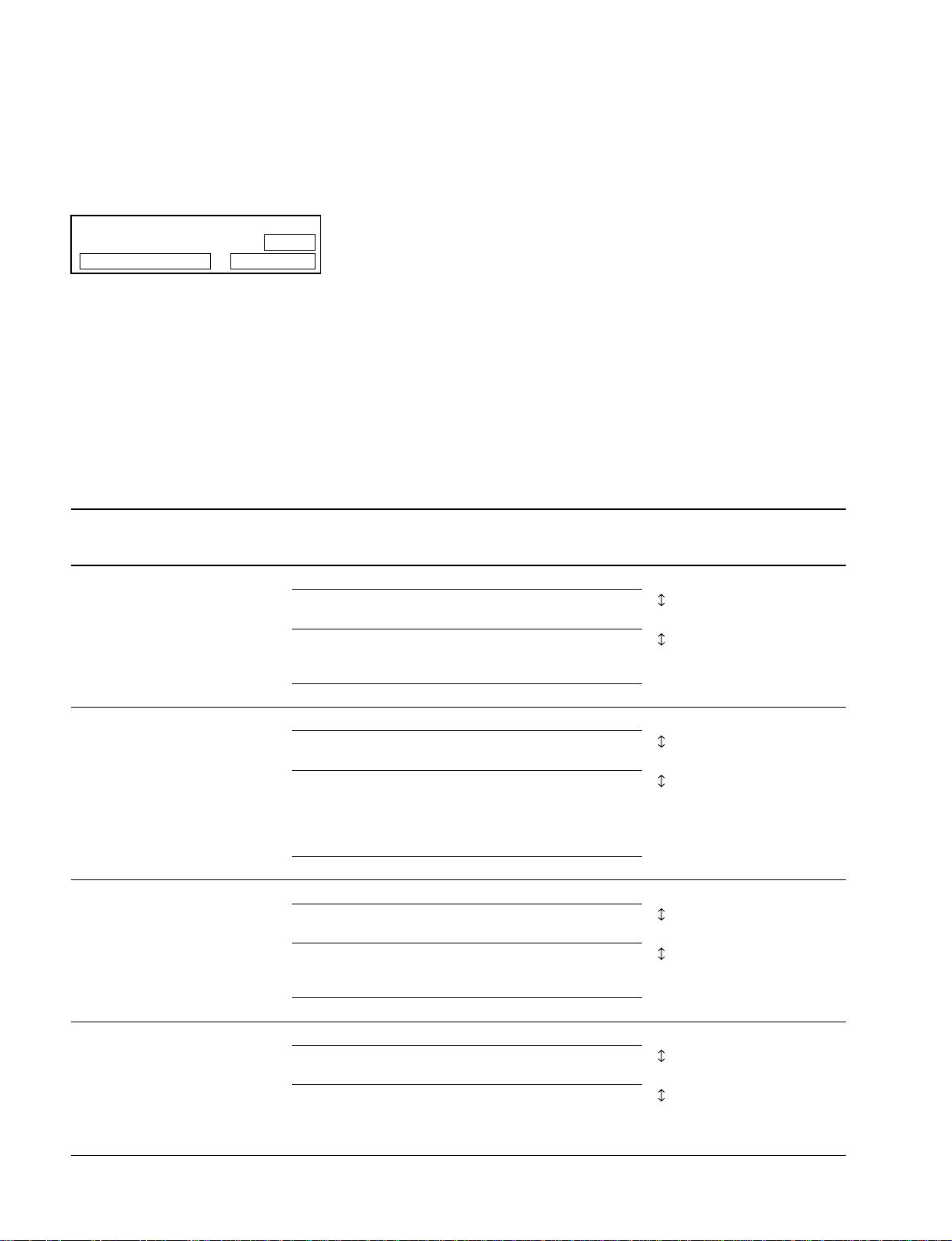
1-11. Note on Battery Compartment
Frame Replacement
When replacing the frame of the battery compartment,
attach the battery labels on the new frame as shown in the
figure below.
The LCD indicates 0.0 dB in the loopback state under the
following conditions:
Conditions
LEVEL (output level select) switch: +4 dBu
LINE/MIC/MIC +48V switch: LINE
Input gain control: +10 dB (fully
counterclockwise)
Specification
0.0 dB ±2.0 dB
Check route
IC612 (DSP) ↔ IC508, 509 (DAC) ↔ IC201, 202, 204
(audio output circuit) ↔ OUTPUT board ↔ INPUT
board ↔ IC001, 002 (head amplifier) ↔ IC612 (DSP)
If a result of a check is out of specification, the analog
audio circuit is defective. Locate the defective part using
an audio analyzer.
Top
Battery
label
Battery
label
Bottom
DMX-P01
1-15

 Loading...