

Page 1
2-661-567-11(1)
DVD Home Theatre
System
Operating Instructions
DAV-DZ810W
©2006 Sony Corporation
Page 2
3
WARNING
To reduce the risk of fire or electric
shock, do not expose this apparatus to
rain or moisture.
Do not install the appliance in a confined space, such
as a bookcase or built-in cabinet.
To prevent fire, do not cover the ventilation of the
apparatus with news papers, table-cloths, curtains, etc.
And don’t place lighted candles on the apparatus.
To prevent fire or shock hazard, do not place objects
filled with liquids, such as vases, on the apparatus.
Don’t throw away the battery with
general house waste, dispose of it
correctly as chemical waste.
This appliance is
classified as a CLASS 1
LASER product. This
marking is located on the
rear or bottom exterior.
NOTICE FOR THE CUSTOMERS IN THE
UNITED KINGDOM
A moulded plug complying with BS1363 is fitted to
this equipment for your safety and convenience.
Should the fuse in the plug supplied need to be
replaced, a fuse of the same rating as the supplied one
and approved by ASTA or BSI to BS1362, (i.e.,
marked with mark or mark) must be used.
If the plug supplied with this equipment has a
detachable fuse cover, be sure to attach the fuse cover
after you change the fuse. Never use the plug without
the fuse cover.
If you should lose the fuse cover, please contact your
nearest Sony service station.
Precautions
Safety
• If anything falls into the cabinet, unplug the unit and
have it checked by qualified personnel before
operating it any further.
• The unit is not disconnected from the AC power
source (mains) as long as it is connected to the wall
outlet (mains), even if the unit itself has been turned
off.
• Unplug the unit from the wall outlet if you do not
intend to use it for an extended period of time. To
disconnect the cord, pull it out by the plug, never by
the cord.
Installing
• Allow adequate air circulation to prevent internal
heat buildup.
• Do not place the unit on surfaces (rugs, blankets, etc.)
or near materials (curtains, draperies) that may block
the ventilation slots.
• Do not install the unit near heat sources such as
radiators, or air ducts, or in a place subject to direct
sunlight, excessive dust, mechanical vibration, or
shock.
• Do not install the unit in an inclined position. It is
designed to be operated in a horizontal position only.
• Keep the unit and discs away from equipment with
strong magnets, such as microwave ovens, or large
loudspeakers.
• Do not place heavy objects on the unit.
• If the unit is brought directly from a cold to a warm
location, moisture may condense inside the DVD
Home Theatre System and cause damage to the
lenses. When you first install the unit, or when you
move it from a cold to a warm location, wait for about
30 minutes before operating the unit.
Disposal of Old
Electrical & Electronic
Equipment (Applicable
in the European Union
and other European
countries with separate
collection systems)
This symbol on the product or on
its packaging indicates that this
product shall not be treate d as household waste. Instead
it shall be handed over to the applicable collection
point for the recycling of electrical and electronic
equipment. By ensuring this product is disposed of
correctly, you will help prevent potential negative
consequences for the environment and human health,
which could otherwise be caused by inappropriate
waste handling of this product. The recycling of
materials will help to conserve natural resources. For
more detailed information about recycling of this
product, please contact your local city office, your
household waste disposal service or the shop where
you purchased the product.
Welcome!
Thank you for purchasing Sony DVD Home
Theatre System. Before operating this system,
please read this manual thoroughly and retain it
for future reference.
GB
2
Page 3

Table of Contents
Welcome! ................................................ 2
About This Manual ................................. 5
This System Can Play the Following
Discs ................................................. 5
Getting Started – BASIC –
Step 1: Assembling the Speakers
and Installing the Surround
Amplifier .................................... 9
Step 2: Connecting the System and
TV ............................................. 15
Step 3: Positioning the System... 19
Step 4: Performing the Quick
Setup........................................ 20
Getting Started – ADVANCED –
Turning off the Demonstration ............. 24
Installing the Speakers and the IR
transmitter on a Wall ...................... 25
TV Hookup (Advanced) ....................... 27
Other Component Hookup.................... 31
Basic Operations
Playing Discs ................................ 33
Enjoying the Radio or Other
Components............................ 34
Enjoying TV or VCR Sound from All
Speakers.................................. 35
Selecting the Movie or Music
Mode ........................................ 36
Sound Adjustments
Enjoying Surround Sound by Using Sound
Field ................................................ 37
Enjoying Multiplex Broadcast Sound... 39
(DUAL MONO)
Various Functions for Playing
Discs
Searching for a Particular Point
on a Disc ......................................... 40
(Scan, Slow-motion Play, Freeze
Frame)
Searching for a Title/Chapter/Track/
Scene, etc. ....................................... 41
Searching by Scene ............................... 42
(Picture Navigation)
Resuming Playback from the Point Where
You Stopped the Disc..................... 43
(Resume Play)
Creating Your Own Program................ 44
(Program Play)
Playing in Random Order ..................... 45
(Shuffle Play)
Playing Repeatedly ............................... 46
(Repeat Play)
Using the DVD’s Menu........................ 47
Changing the Sound.............................. 48
Selecting [ORIGINAL] or [PLAY LIST]
on a DVD-R/DVD-RW .................. 50
Viewing Information About
the Disc........................................... 50
Changing the Angles ............................ 53
Displaying the Subtitles........................ 53
Adjusting the Delay Between the Picture
and Sound....................................... 54
(A/V SYNC)
Selecting a Playback Area for a Super
Audio CD ....................................... 54
About MP3 Audio Tracks and JPEG
Image Files ..................................... 55
Playing DATA CDs or DATA DVDs with
MP3 Audio Tracks and JPEG Image
Files ................................................ 57
Playing Audio Tracks and Images as a
Slide Show with Sound .................. 59
Enjoying DivX® Videos ...................... 61
Playing VIDEO CDs with PBC Functions
(Ver.2.0) ......................................... 63
(PBC Playback)
Tuner Functions
Presetting Radio Stations...................... 64
Listening to the Radio........................... 64
Using the Radio Data System (RDS) ... 66
Other Operations
Controlling the TV with the Supplied
Remote ........................................... 67
Using the THEATRE SYNC
Function.......................................... 68
Using the Sound Effect......................... 69
Using the Sleep Timer .......................... 70
GB
3
Page 4

Changing the Brightness of the Front
Panel Display .................................. 70
Advanced Settings and
Adjustments
Locking Discs ....................................... 71
(CUSTOM PARENTAL
CONTROL, PARENTAL
CONTROL)
Getting Optimal Surround Sound for a
Room .............................................. 74
(SPEAKER FORMATION)
Calibrating the Appropriate Settings
Automatically ................................. 76
(AUTO CALIBRATION)
Using the Setup Display........................ 78
Setting the Display or Sound Track
Language ........................................ 79
[LANGUAGE SETUP]
Settings for the Display......................... 80
[SCREEN SETUP]
Custom Settings .................................... 82
[CUSTOM SETUP]
Settings for the Speakers....................... 83
[SPEAKER SETUP]
Returning to the Default Settings..........86
Additional Information
Precautions ............................................ 87
Notes about the Discs............................ 88
Troubleshooting .................................... 88
Self-diagnosis Function ........................ 92
(When letters/numbers appear in
the display)
Specifications ........................................ 93
Glossary ................................................ 94
Language Code List .............................. 98
Index to Parts and Controls................... 99
Guide to the Control Menu Display.... 102
DVD Setup Display List .....................105
AMP Menu List .................................. 106
Index ................................................... 107
GB
4
Page 5
About This Manual
This System Can Play the
• The instructions in this manual describe the
controls on the remote. You can also use the
controls on the system if they have the same or
similar names as those on the remote.
• The Control Menu items may be different
depending on the area.
• “DVD” may be used as a general term for
DVD VIDEOs, DVD+RWs/DVD+Rs, and
DVD-RWs/DVD-Rs.
• Measurements are expressed in feet (ft) for
North American models.
• The following symbols are used in this
manual.
Symbol Meaning
Functions available for DVD
VIDEOs, DVD-Rs/DVD-RWs in
video mode, and DVD+Rs/
DVD+RWs
Functions available for DVD-Rs/
DVD-RWs in VR (Video
Recording) mode
Functions available for VIDEO
CDs (including Super VCDs or CDRs/CD-RWs in video CD format or
Super VCD format)
Functions available for Super Audi o
CDs
Functions available for music CDs
or CD-Rs/CD-RWs in music CD
format
Functions available for DATA CDs
(CD-ROMs/CD-Rs/CD-RWs)
containing MP31) audio tracks,
JPEG image files, and DivX
video files
Functions available for DATA
DVDs (DVD-ROMs/DVD-Rs/
DVD-RWs/DVD+Rs/DVD+RWs)
containing MP31) audio tracks,
JPEG image files, and DivX
video files
1)
MP3 (MPEG1 Audio Layer 3) is a standard format
defined by ISO/MPEG which compresses audio data.
2)
DivX® is a video file compression technology,
developed by DivX, Inc.
3)
DivX, DivX Certified, and associated logos are
trademarks of DivX, Inc. and are used under license.
2)3)
2)3)
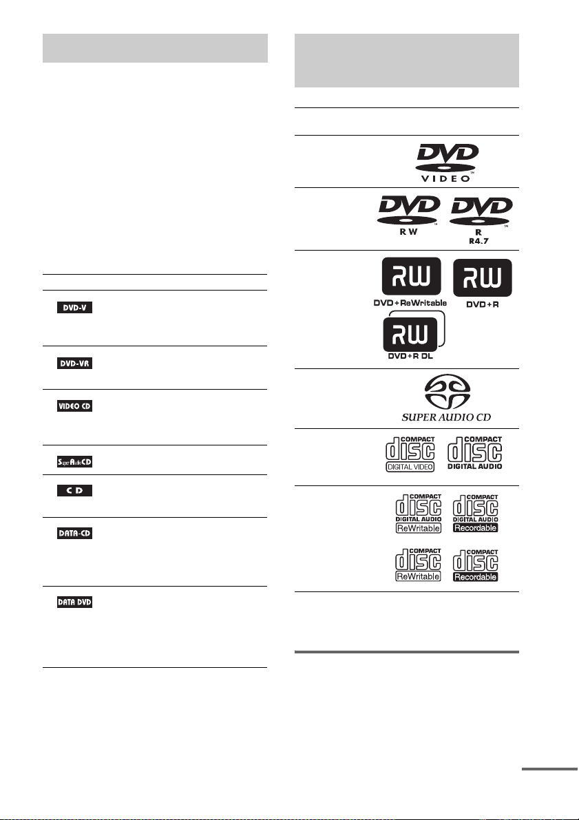
Following Discs
Format of
discs
DVD VIDEO
DVD-RW/
DVD-R
DVD+RW/
DVD+R
Super Audio
CD
VIDEO CD
(Ver. 1.1 and
2.0 discs)/
Audio CD
CD-RW/CD-R
(audio data)
(MP3 files)
(JPEG files)
“DVD+RW,” “DVD-RW,” “DVD+R,”
“DVD VIDEO,” and the “CD” logos are trademarks.
Note about CDs/DVDs
The system can play CD-ROMs/CD-Rs/CDRWs recorded in the following formats:
– audio CD format
– video CD format
Disc logo
continued
GB
5
Page 6

– MP3 audio tracks, JPEG image files, and
DivX video files of format conforming to ISO
9660 Level 1/Level 2, or its extended format,
Joliet
The system can play DVD-ROMs/DVD+RWs/
DVD-RWs/DVD+Rs/DVD-Rs recorded in the
following formats:
– MP3 audio tracks, JPEG image files and
DivX video files of format conforming to
UDF (Universal Disc Format)
Example of discs that the system cannot play
The system cannot play the following discs:
• CD-ROMs/CD-Rs/CD-RWs other than those
recorded in the formats listed on page 5
• CD-ROMs recorded in PHOTO CD format
• Data part of CD-Extras
• DVD Audios
• DATA DVDs that do not contain MP3 audio
tracks, JPEG image files, or DivX video files.
• DVD-RAMs
Also, the system cannot play the following
discs:
• A DVD VIDEO with a different region code
(page 6, 96)
• A disc that has a non-standard shape (e.g.,
card, heart)
• A disc with paper or stickers on it
• A disc that has the adhesive of cellophane tape
or a sticker still left on it
Notes about CD-R/CD-RW/DVD-R/
DVD-RW/DVD+R/DVD+RW
In some cases, CD-R/CD-RW/DVD-R/DVDRW/DVD+R/DVD+RW cannot be played on
this system due to the recording quality or
physical condition of the disc, or the
characteristics of the recording device and
authoring software.
The disc will not play if it has not been correctly
finalized. For more information, see the
operating instructions for the recording device.
Note that some playback functions may not
work with some DVD+RWs/DVD+Rs, even if
they have been correctly finalized. In this case,
view the disc by normal playback. Also some
DATA CDs/DATA DVDs created in Packet
Write format cannot be played.
Music discs encoded with
copyright protection
technologies
This product is designed to play back discs that
conform to the Compact Disc (CD) standard.
Recently, various music discs encoded with
copyright protection technologies are marketed
by some record companies. Please be aware that
among those discs, there are some that do not
conform to the CD standard and may not be
playable by this product.
Note on DualDisc
A DualDisc is a two sided disc product which
mates DVD recorded material on one side with
digital audio material on the other side.
However, since the audio material side does not
conform to the Compact Disc (CD) standard,
playback on this product is not guaranteed.
About Multi Session CD
• This system can play Multi Session CDs when
an MP3 audio track is contained in the first
session. Any subsequent MP3 audio tracks
recorded in later sessions can also be played
back.
• This system can play Multi Session CDs when
a JPEG image file is contained in the first
session. Any subsequent JPEG image files
recorded in later sessions can also be played
back.
• If audio tracks and images in music CD format
or video CD format are recorded in the first
session, only the first session will be played
back.
Region code
Your system has a region code printed on the
bottom exterior and will only play DVDs
labeled with the same region code.
DVD VIDEOs labeled will also play on this
system.
ALL
GB
6
Page 7

If you try to play any other DVD VIDEO, the
message [Playback prohibited by area
limitations.] will appear on the TV screen.
Depending on the DVD VIDEO, no region code
indication may be given even though playing the
DVD VIDEO is prohibited by area restrictions.
Note on playback operations of DVDs and VIDEO CDs
Some playback operations of DVDs and VIDEO
CDs may be intentionally set by software
producers. Since this system plays DVDs and
VIDEO CDs according to the disc contents the
software producers designed, some playback
features may not be available. Also, refer to the
instructions supplied with the DVDs or VIDEO
CDs.
Copyrights
This product incorporates copyright protection
technology that is protected by U.S. patents and
other intellectual property rights. Use of this
copyright protection technology must be
authorized by Macrovision, and is intended for
home and other limited viewing uses only unless
otherwise authorized by Macrovision. Reverse
engineering or disassembly is prohibited.
This system incorporates with Dolby* Digital
and Dolby Pro Logic (II) adaptive matrix
surround decoder and the DTS** Digital
Surround System.
* Manufactured under license from Dolby
Laboratories.
“Dolby,” “Pro Logic,” and the double-D symbol are
trademarks of Dolby Laboratories.
** Manufactured under license from Digital Theater
Systems, Inc.
“DTS” and “DTS Digital Surround” are trademarks
of Digital Theater Systems, Inc.
GB
7
Page 8
Getting Started – BASIC –
See Unpacking in Specifications, page 93.
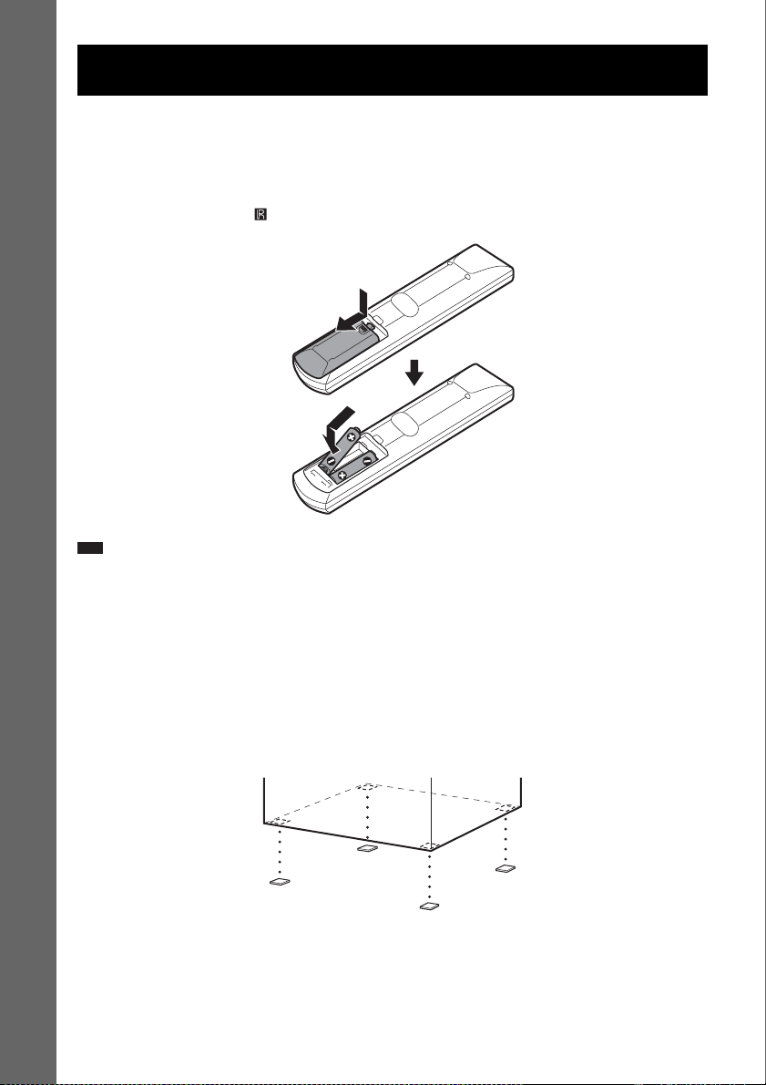
Inserting batteries into the remote
You can control the system using the supplied remote. Insert two R6 (size AA) batteries by matching
the 3 and # ends on the batteries to the markings inside the compartment. When using the remote,
point it at the remote sensor on the system.
Getting Started – BASIC –
Note
• Do not leave the remote in an extremely hot or humid place.
• Do not use a new battery with an old one.
• Do not drop any foreign object into the remote casing, particularly when replacing the batteries.
• Do not expose the remote sensor to direct light from the sun or lighting apparatus. Doing so may cause a
malfunction.
• If you do not intend to use the remote for an extended period of time, remove the batteries to avoid possible damage
from battery leakage and corrosion.
Attaching the foot pads to the subwoofer
Attach the supplied foot pads to the bottom of the subwoofer to stabilize the subwoofer and prevent it
from slipping.
GB
8
Page 9
p
Step 1: Assembling the Speakers and Installing the Surround Amplifier
Before connecting the speakers, attach the speaker stand to the speaker.
About how to connect the speaker cords to the SPEAKER jacks, see page 16.
The IR receiver cord should be used for the surround speaker (L) only. The illustrations below show
how to install the surround speaker (L).
Note
• Spread a cloth on the floor to avoid damaging the floor.
Ti
• You can use the speaker without the speaker stand by installing it on the wall (page 25).
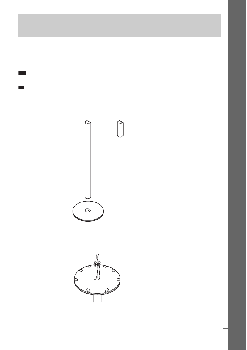
1 Secure the post to the base.
The long post is for floor use, the short post is for tabletop use.
Getting Started – BASIC –
Post (long)
2 Secure the base with the screws.
Screws with washer (long) (3)
(supplied)
or
Base
Post (short)
Bottom of the base
continued
GB
9
Page 10
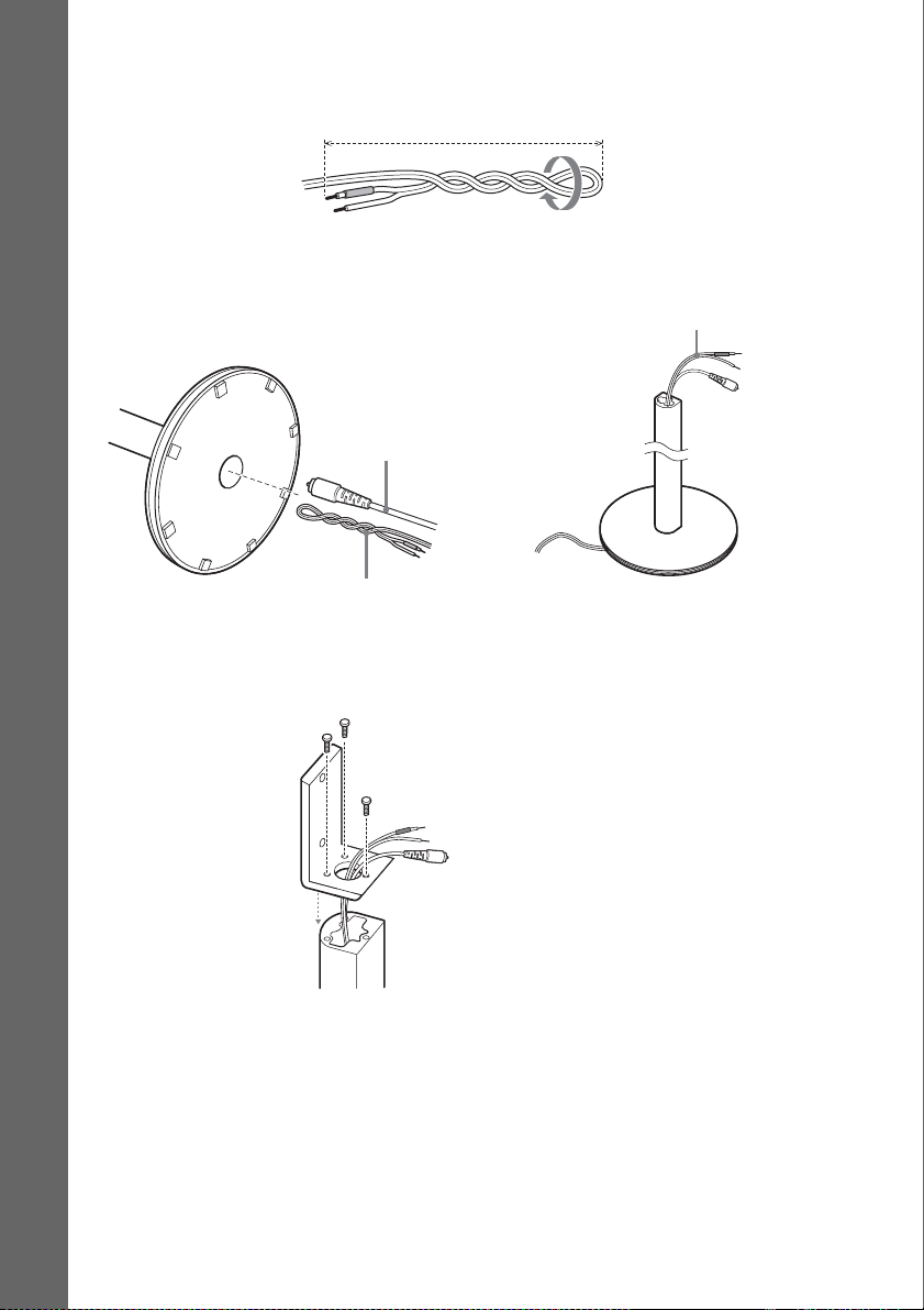
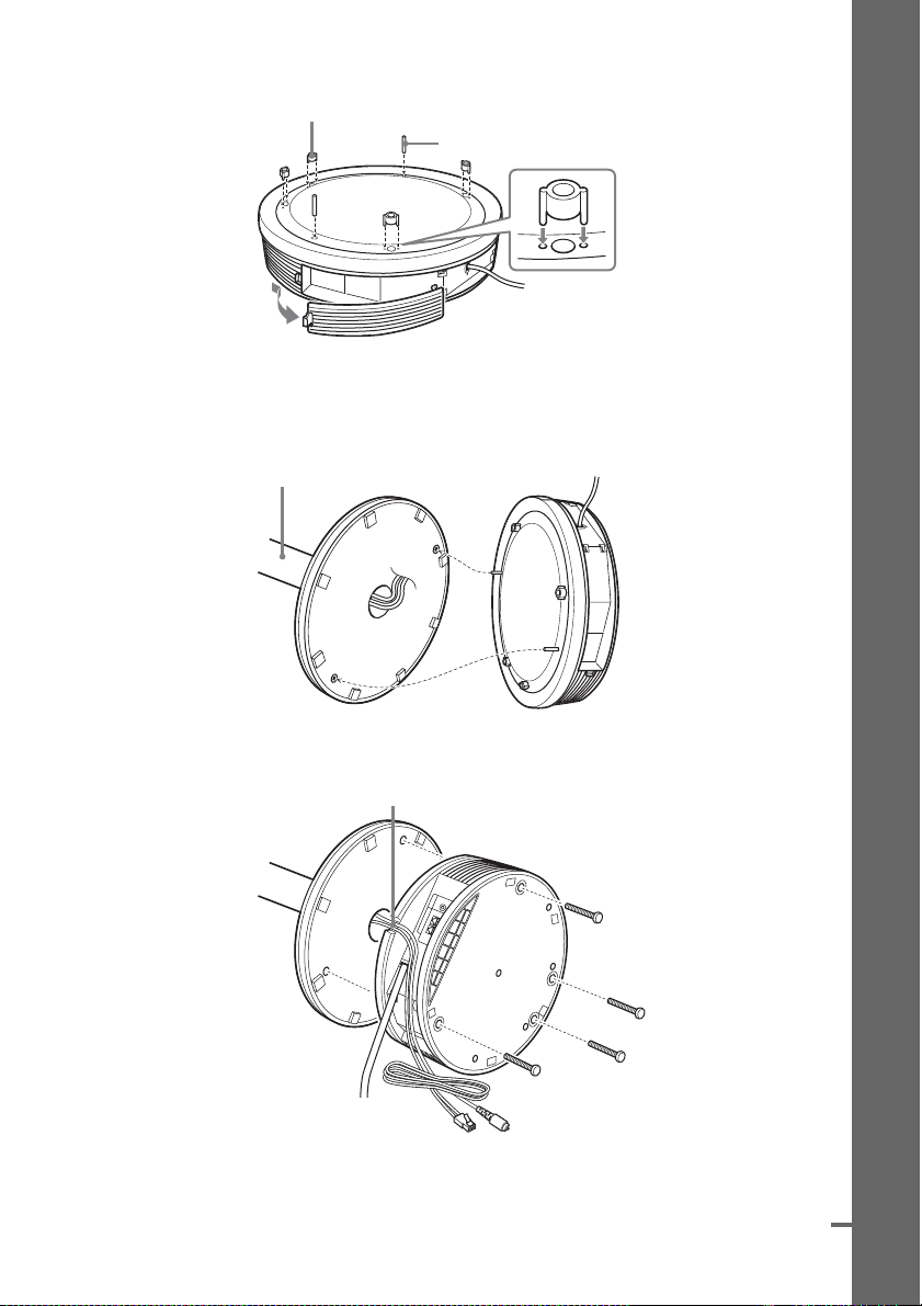
3 Pull the speaker cord out to a straight length of about 700 mm (28 inch). Fold back about
100 mm (4 inch) and twist together.
About 100 mm (4 inch)
4 Draw the IR receiver cord first, and then the speaker cord through the hole on the base.
Stand the speaker up, and untwist and straighten out the speaker cord.
Untwist and straighten out the speaker cord.
Getting Started – BASIC –
Bottom of the base
IR receiver cord
,
Speaker cord
5 Secure the pedestal to the post with the screws.
Screws with washer (long) (3)
(supplied)
10
GB
Page 11
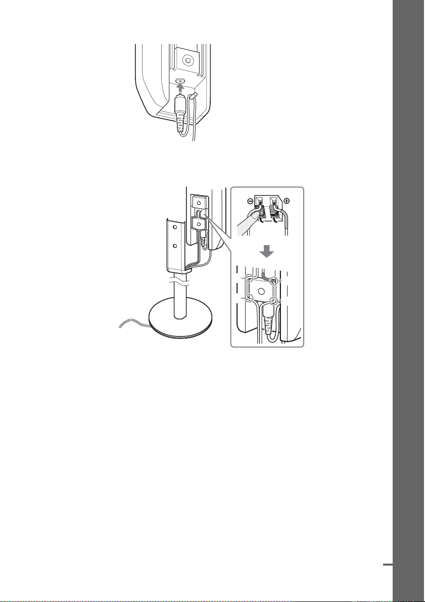
6 Connect the IR receiver cord to the speaker and run the cord around the pin.
7 Connect the speaker cords to the speaker. Then run the cords through the slots (A, B,
C, and D) all the way.
Getting Started – BASIC –
A
C
B
D
continued
11
GB
Page 12
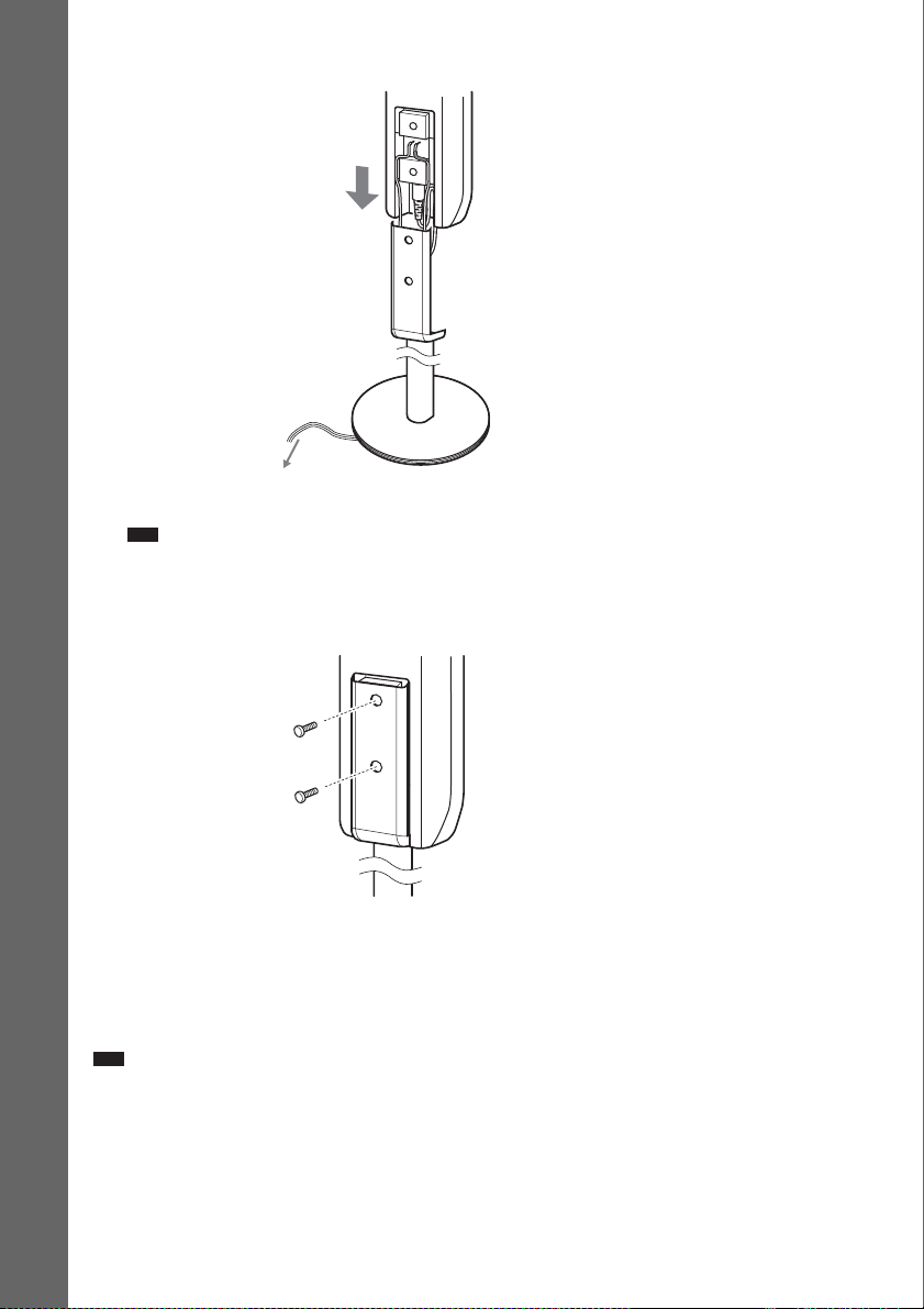
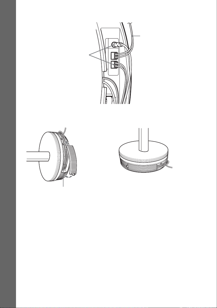
8 Slide the speaker down slowly onto the pedestal.
Getting Started – BASIC –
Adjust the length of the speaker cord (and the IR receiver cord).
Note
• Do not catch the speaker cord (and the IR receiver cord) between the speaker and the pedestal.
• Do not drop the speaker when mounting.
9 Secure the speaker with the screws in order 1 to 2.
1
2
Screws with washer (short) (2)
(supplied)
Installing the surround amplifier (speaker base)
You can put on the surround speaker (L) to the surround amplifier, the surround speaker (R) to the
speaker base.
The illustrations below show how to attach the surround speaker (L) to the surround amplifier.
Note
• Lay the surround speakers down when attaching the surround amplifier and speaker base.
GB
12
Page 13
1 Attach the spacers.
Spacers (4) (supplied)
Guide pins (2) (supplied)
Push open the cover (surround amplifier only).
2 Attach the surround amplifier (speaker base) to the surround speaker with the guide
pins.
Rear of surround speaker
Getting Started – BASIC –
3 Secure the surround amplifier (speaker base) with the screws to the circle marked holes.
Run cords through the slot.
Screws (4)
(supplied)
continued
13
GB
Page 14
4 Connect the speaker cords and the IR receiver cord to the surround amplifier.
From surround speaker (R).
SS-TS56W
From surround speaker (L).
SPEAKER
SUR L SUR R
Getting Started – BASIC –
5 Bundle the cords into the storage space. Stand the speaker up.
The speaker base has storage space in the back.
,
14
Attach the cover
(surround amplifier only).
Storage space
GB
Page 15

Step 2: Connecting the System and TV
This hookup is the basic connection of the system to the speakers and TV. For other TV connections,
see page 27. For other component connection, see page 31.
To accept progressive signals, see page 29.
Refer to the connection diagram below, and read the additional information from 1 to 4 on the
following pages.
Front speaker (R)
AC power cord
(mains lead)
SPEAKER
FRONT R FRONT L SUR R SUR LCENTER WOOFER
Center speaker
AM loop antenna (aerial)
LINE1 LINE2
DIGITAL IN
OPTICAL
OUT
(DVD ONLY)
DIGITAL IN
COAXIAL
COMPONENT VIDEO OUT
YPB/CBPR/C
RLAUDIO IN
LINE1
R
(DVD ONLY)
Front speaker (L)
EURO AV
OUTPUT(TO TV)
DIR-T1
COAXIAL
FM
AM
75
Getting Started – BASIC –
Subwoofer
TV
SPEAKER
SUR L SUR R
IR transmitter
Surround speaker (L)Surround speaker (R)
SS-TS56W
AC power cord
FM wire antenna
(aerial)
(mains lead)
continued
15
GB
Page 16
1 Connecting the Speakers
Required cords
The connector and color tube of the speaker cords are the same color as the label of the jacks to be
connected.
Note
Getting Started – BASIC –
• Do not catch the speaker cord insulation in the SPEAKER jack.
Color tube
(+)
(–)
To avoid short-circuiting the speakers
Short-circuiting of the speakers may damage the system. To prevent this, be sure to follow these
precautions when connecting the speakers. Make sure the bare wire of each speaker cord does not touch
another speaker terminal or the bare wire of another speaker cord, such as shown below.
Stripped speaker cord is
touching another speaker
terminal.
Stripped cords are touching each
other due to excessive removal of
insulation.
After connecting all the components, speakers, and AC power cord (mains lead), output a test tone to
check that all the speakers are connected correctly. For details on outputting a test tone, see page 85.
If no sound is heard from a speaker while outputting a test tone, or a test tone is output from a speaker
other than the one currently displayed on the Setup Display, the speaker may be short-circuited. If this
happens, check the speaker connection again.
Note
• Be sure to match the speaker cord to the appropriate terminal on the components: 3 to 3, and # to #. If the cords
are reversed, the sound will lack bass and may be distorted.
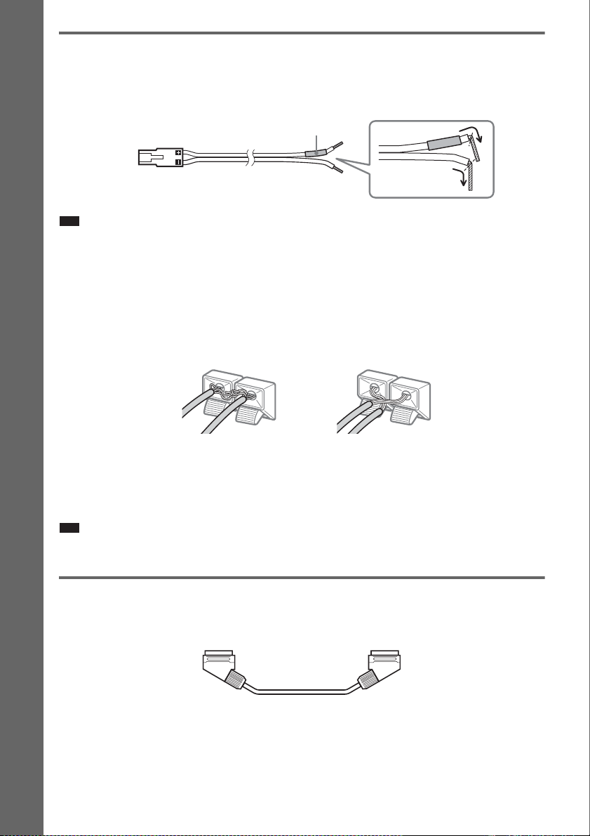
2 Connecting the TV
Required cords
SCART (EURO AV) cord (not supplied)
.
Be sure to connect the SCART (EURO AV) cord to the EURO AV T OUTPUT (TO TV) jack on the
system.
When you connect using the SCART (EURO AV) cord, check that the TV conforms to S video or RGB
signals. If the TV conforms to S video, change the input mode of the TV to RGB signals. Refer to the
operating instructions supplied with the TV to be connected.
GB
16
Page 17
Ti
p
p
• When you want to output the TV sound or stereo sound of a 2 channel source from the 6 speakers, select the “Dolby
Pro Logic,” “Dolby Pro Logic II MOVIE,” or “Dolby Pro Logic II MUSIC” sound field (page 37).
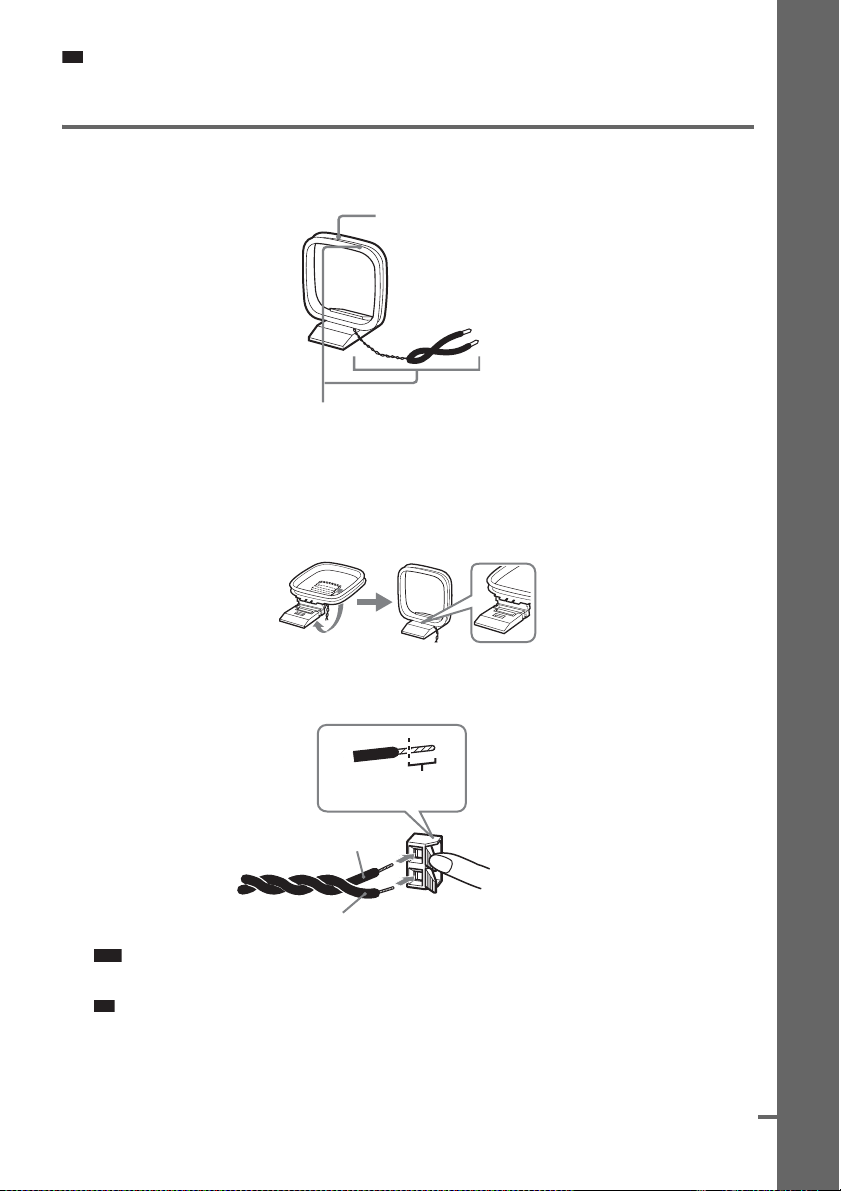
3 Connecting the Antenna (Aerial)
To connect the AM antenna (aerial)
Plastic stand (supplied)
Antenna (aerial)
The shape and the length of the antenna (aerial) is designed to receive AM signals. Do not dismantle
or roll up the antenna (aerial).
1 Remove only the loop part from the plastic stand.
2 Set up the AM loop antenna (aerial).
Getting Started – BASIC –
3 Connect the cords to the AM antenna (aerial) terminals.
Cord (A) or cord (B) can be connected to either terminal.
Insert until this
part.
A
B
Note
• Do not place the AM loop antenna (aerial) near the system or other AV equipment, as noise may result.
Ti
• Adjust the direction of the AM loop antenna (aerial) for best AM broadcast sound.
AM
Insert the cords pushing
down the terminal clamp.
4 Make sure the AM loop antenna (aerial) is connected firmly by pulling softly.
continued
17
GB
Page 18
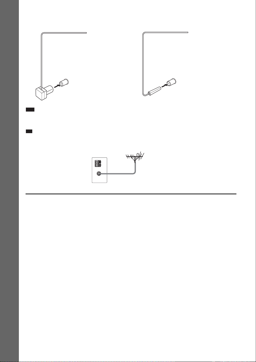
To connect the FM wire antenna (aerial)
p
Connect the FM wire antenna (aerial) to the COAXIAL FM 75 Ω jack.
FM wire antenna (aerial)
(supplied)
COAXIAL FM 75 Ω jack
or
FM wire antenna (aerial)
(supplied)
COAXIAL FM 75 Ω jack
Getting Started – BASIC –
Note
• Be sure to fully extend the FM wire antenna (aerial).
• After connecting the FM wire antenna (aerial), keep it as horizontal as possible.
Ti
• If you have poor FM reception, use a 75-ohm coaxial cable (not supplied) to connect the system to an outdoor FM
antenna (aerial) as shown below.
System
Outdoor FM antenna (aerial)
4 Connecting the AC power cord (mains lead)
Before connecting the AC power cord (mains lead) of this system to a wall outlet (mains), connect the
speakers to the system.
Install this system so that the power cord can be unplugged from the wall socket immediately in the
event of trouble.
GB
18
Page 19
p
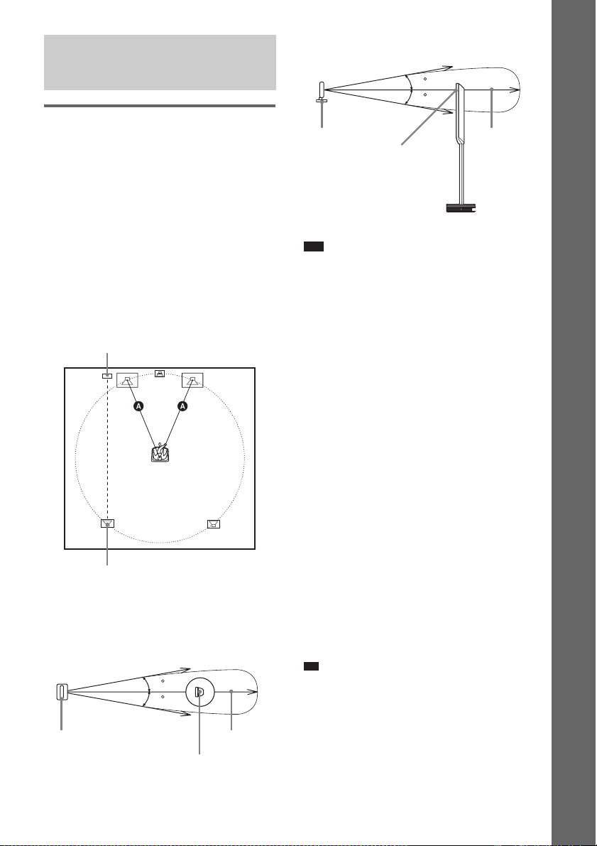
Step 3: Positioning the System
Positioning the speakers
For the best possible surround sound, all the
speakers other than the subwoofer should be the
same distance from the listening position (A).
The front speakers can be placed from 0.0 to 7.0
meters (0 to 23 ft) (A) from the listening
position.
Install the IR transmitter and IR receiver of the
surround speaker (L) in direct line with each
other. For details, see “To adjust the IR
transmitter and IR receiver of the surround
speaker (L)” (page 22).
Place speakers as illustrated below.
IR transmitter
IR receiver of the surround speaker (L)
The following diagram indicates the infrared
transmission area (the range that the infrared
rays can reach).
Top view
Infrared signal
10
10
IR transmitter
Approx. 10m
(33 ft)
Surround speaker (L)
Side view
Infrared signal
10
10
IR transmitter
IR receiver
Note
• Do not install the surround speaker (L) (or IR
receiver) in a place exposed to direct sunlight or
strong light such as an incandescent lamp.
• The cord of the IR transmitter and IR receiver is for
this system only.
• Do not step on or place objects other than supplied
speakers on the surround amplifier and speaker base.
• When you install the speaker on the surround
amplifier or speaker base, make sure the speaker is
properly stacked.
• Do not set the speakers in an inclined position.
• Do not place the speakers in locations that are:
– Extremely hot or cold
– Dusty or dirty
– Very humid
– Subject to vibrations
– Subject to direct sunlight
• Use caution when placing the speakers and/or
speaker stands (not supplied) that are attached with
the speakers on a specially treated (waxed, oiled,
polished, etc.) floor, as staining or discoloration may
result.
• When cleaning, use a soft cloth such as a cleaning
cloth for glasses.
• Do not use any type of abrasive pad, scouring
powder, or solvent such as alcohol or benzine.
• Do not lean or hang on the speaker, as the speaker
may fall down.
Ti
• If transmission is poor, you can also connect the
surround speakers to the system by the speaker cords
(OPTION) (supplied).
• When you change the positions of the speakers, it is
recommended that you change the settings. For
details, see “Getting Optimal Surround Sound for a
Room” (page 74) and “Calibrating the Appropriate
Settings Automatically” (page 76).
Approx. 10m
(33 ft)
Surround speaker (L)
Getting Started – BASIC –
GB
19
Page 20
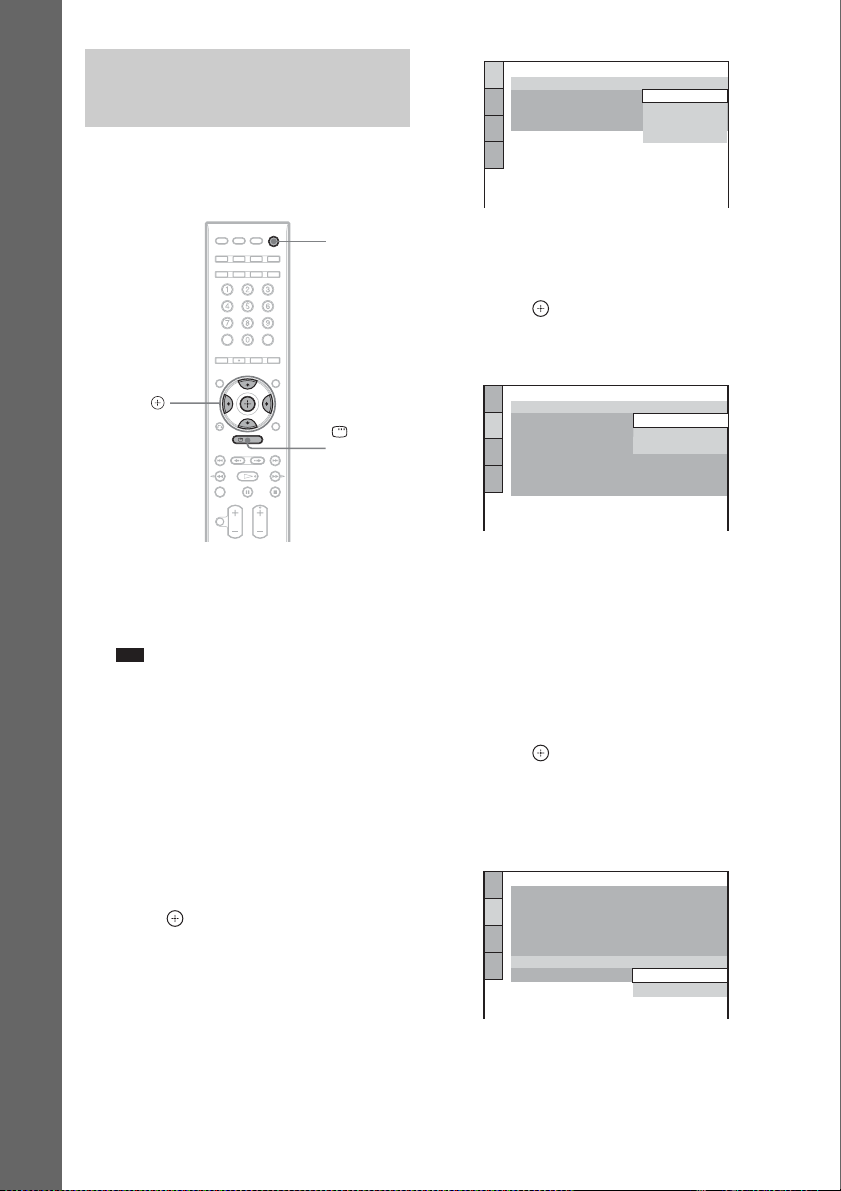
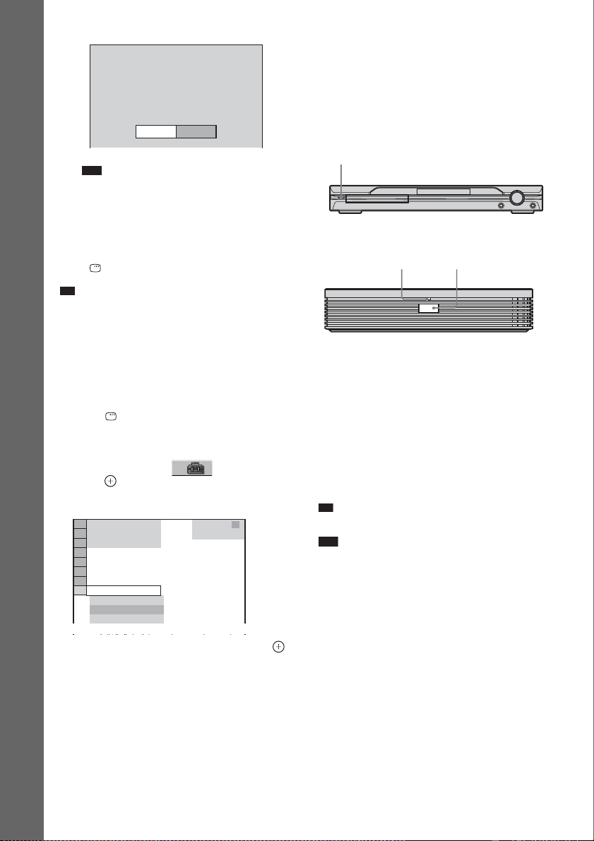
Step 4: Performing the Quick Setup
Follow the steps below to make the minimum
number of basic adjustments for using the
system.
LANGUAGE SETUP
OSD:
MENU:
AUDIO:
SUBTITLE:
ENGLISH
ENGLISH
FRENCH
SPANISH
PORTUGUESE
Getting Started – BASIC –
C/X/x/c,
1 Turn on the TV.
2 Press [/1 and POWER on the surround
amplifier.
Note
• Disconnect the headphones when you perform
the Quick Setup. You cannot operate steps after
12 with the headphones connected.
• Make sure that the function is set to “DVD.”
3 Switch the input selector on your TV so
that the signal from the system
appears on the TV screen.
[Press [ENTER] to run QUICK SETUP.]
appears at the bottom of the screen. If this
message does not appear, display the Quick
Setup and perform again (page 22).
4 Press without inserting a disc.
The Setup Display for selecting the
language used in the on-screen display
appears.
"/1
DISPLAY
5 Press X/x to select a language.
The system displays the menu and subtitles
in the selected language.
6 Press .
The Setup Display for selecting the aspect
ratio of the TV to be connected appears.
SCREEN SETUP
TV TYPE:
HDMI RESOLUTION:
YC
BCR
/RGB (HDMI):
SCREEN SAVER:
BACKGROUND:
LINE:
4:3 OUTPUT:
4:3 LETTER BOX
JACKET PICTURE
16:9
16:9
4:3 PAN SCAN
VIDEO
FULL
7 Press X/x to select the setting that
matches your TV type.
x If you have a 4:3 standard TV
[4:3 LETTER BOX] or [4:3 PAN SCAN]
(page 80)
x If you have a wide-screen TV or a 4:3
standard TV with a wide-screen mode
[16:9] (page 80)
8 Press .
The Setup Display for selecting the output
method for video signals from the EURO
AV T OUTPUT (TO TV) jack on the rear
panel of the system appears.
SCREEN SETUP
TV TYPE:
HDMI RESOLUTION:
BCR
/RGB (HDMI):
YC
SCREEN SAVER: ON
BACKGROUND:
LINE:
4:3 OUTPUT:
JACKET PICTURE
16:9
AUTO
BCR
YC
VIDEO
VIDEO
FULL
RGB
20
9 Press X/x to select the output method
for video signals.
• [VIDEO]: outputs video signals.
GB
Page 21
• [RGB]: outputs RGB signals.
Note
• If your TV does not accept RGB signals, no
picture appears on the TV screen even if you
select [RGB]. Refer to the instructions supplied
with your TV.
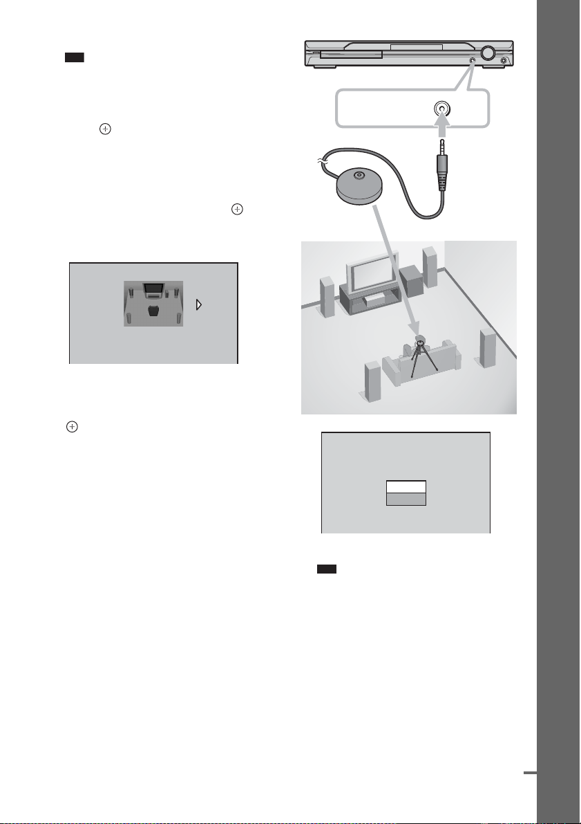
10Press .
The Setup Display for selecting the speaker
formation appears.
11Press C/c to select the speaker
formation image as the speakers are
actually positioned, then press .
For details, see “Getting Optimal Surround
Sound for a Room” (page 74).
SPEAKER FORMATION
STANDARD(WIRELESS)
12Connect the calibration mic to the
A.CAL MIC jack on the front panel and
press X/x to select [YES], then press
.
Set up the calibration mic at the ear level
using a tripod, etc. (not supplied). The front
of each speaker should face the calibration
mic, and there should be no obstruction
between the speakers and the calibration
mic. Be quiet during the measurement.
A.CAL MIC
Calibration mic
AUTO CALIBRATION
Connect calibration mic. Start
measurement?
YES
NO
Getting Started – BASIC –
Auto Calibration starts.
Note
• Loud test sound is output when [AUTO
CALIBRATION] starts. You cannot turn the
volume down. Give consideration to children
and neighbor.
• Avoid being in the measurement area and
making noise during the measurement (which
takes about 1 minute), as it may interfere with
measurement.
13 Unplug the calibration mic and press C/
c to select [YES].
Quick Setup is finished. All connections
and setup operations are complete.
continued
21
GB
Page 22
p
p
Measurement complete.
FRONT L :
FRONT R :
CENTER :
SUBWOOFER :
SURROUND L :
SURROUND R :
If OK, unplug calibration mic and select
YES.
Note
YES
5.0m 0.0dB
5.0m
0.0dB
5.0m + 1.0dB
5.0m + 4.0dB
3.0m
-
2.0dB
3.0m
-
2.0dB
NO
• Reflections from walls or the floor may affect
measurements.
Getting Started – BASIC –
• If measurement fails, follow the message then
retry [AUTO CALIBRATION].
To quit the Quick Setup
Press DISPLAY in any Step.
Ti
• If you change the position of the speakers, reset the
speaker settings. See “Getting Optimal Surround
Sound for a Room” (page 74) and “Calibrating the
Appropriate Settings Automatically” (page 76).
• If you want to change any of the settings, see “Using
the Setup Display” (page 78).
To recall the Quick Setup display
1 Press DISPLAY when the system is in
stop mode.
The Control Menu appears.
2 Press X/x to select [SETUP], then
press .
The options for [SETUP] appear.
)
1 2 ( 2 7
)
BNR
1 8 ( 3 4
QUICK
QUICK
CUSTOM
RESET
: :
DVD VIDEO
3 Press X/x to select [QUICK], then press .
The Quick Setup display appears.
To adjust the IR transmitter and
IR receiver of the surround
speaker (L)
After connecting the speakers, surround
amplifier, IR transmitter, and the
AC power cords (mains leads), adjust the
wireless system for good transmission.
"/1
POWER/
ON LINE indicator
POWER
POWER
1 Press "/1 on the system and POWER on
the surround amplifier.
The system and surround amplifier turn on
and the POWER/ON LINE indicator turns
red.
2 Orient the IR transmitter and IR receiver of
the surround speaker (L) to face each other.
Adjust the position until the POWER/ON
LINE indicator turns green.
Ti
• The IR transmitter is movable for easy reorientation.
Note
• Make sure that there is no obstruction such as a
person or object between th e IR transmitter and the IR
receiver of the surround speaker (L). Otherwise, the
sound from the surround speakers may be interrupted.
• If the POWER/ON LINE indicator turns red,
transmission is not occuring. Adjust the position of
the IR transmitter and surround speaker (L) until the
POWER/ON LINE indicator turns green.
• If the POWER/ON LINE indicator flashes red, the IR
receiver is receiving an infrared ray from another
Sony’s wireless product. Move the IR transmitter
and/or the surround speaker (L) so that the POWER/
ON LINE indicator turns green.
GB
22
Page 23

To place the surround speaker (L)
in the (R) position
Depending on the location of the wall outlet
(mains), you can also place the surround speaker
(L) (with the IR receiver) in the (R) position if
necessary.
1 Press AMP MENU.
2 Press X/x repeatedly until “SL SR REV”
appears in the front panel display, then
press or c.
3 Press X/x to select the setting.
•REV ON: Sets the surround speaker (L) (with the
IR receiver) in the (R) position.
•REV OFF: Sets the surround speaker (L) (with the
IR receiver) in the (L) position.
4 Press .
The setting is made.
5 Press AMP MENU.
The AMP menu turns off.
Getting Started – BASIC –
23
GB
Page 24
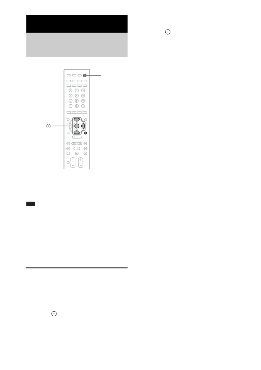
Getting Started – ADVANCED –
Turning off the Demonstration
"/1
X/x/c,
AMP MENU
After connecting the AC power cord (mains
lead), the demonstration appears in the front
panel display. When you press "/1 on the
remote, the demonstration turns off.
Note
• When you press "/1 on the system, the demonstration
does not turn off.
• When you set the demonstration mode in the AMP
menu to on, the demonstration does not turn off even
though you press "/1 on the remote. To turn off the
demonstration, set the demonstration mode to off,
then press "/1 on the remote. When the
demonstration mode is set to off, the system saves
power in standby mode.
• DEMO OFF: sets the demonstration mode
off.
4 Press .
The setting is reflected.
5 Press AMP MENU.
The AMP menu turns off.
Setting the demonstration mode on/off
1 Press AMP MENU.
2 Press X/x repeatedly until “DEMO”
appears in the front panel display, then
press or c.
3 Press X/x to select the setting.
• DEMO ON: sets the demonstration mode
on.
GB
24
Page 25
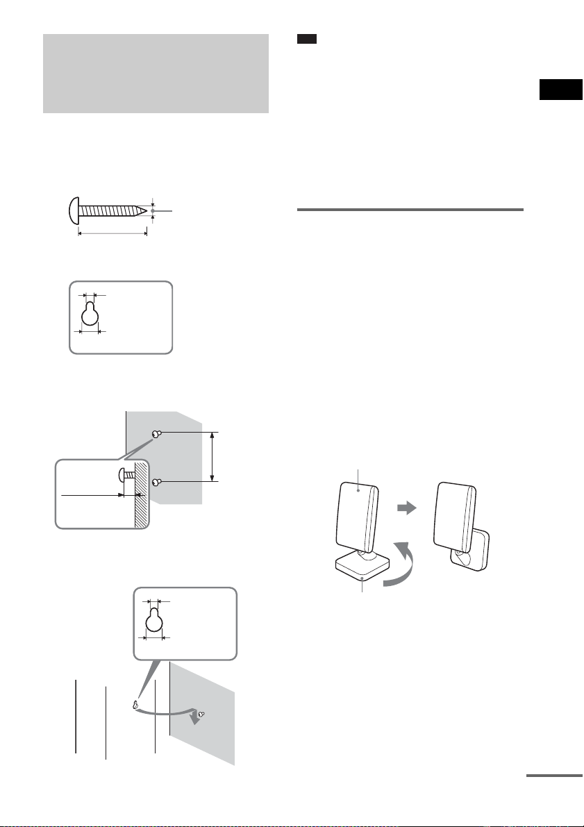
Installing the Speakers and the IR transmitter on a Wall
1 Prepare screws (not supplied) that are
suitable for the hole on the back of
each speaker. See the illustrations
below.
5
4 mm (
/32 inch)
30 mm (1 3/16 inch)
4.6 mm
3
/16 inch)
(
10 mm
13
(
/32 inch)
Hole on the back of
the speaker
Note
• Use screws that are suitable for the wall material and
strength. As a plaster board wall is especially fragile,
attach the screws securely to a beam and fasten them
to the wall. Install the speakers on a vertical and flat
wall where reinforcement is applied.
• Contact a screw shop or installer regarding the wall
material or screws to be used.
• Sony is not responsible for accident or damage
caused by improper installation, insufficient wall
strength or improper screw installation, natural
calamity, etc.
Installing the IR transmitter on a wall
You can hang the IR transmitter on a wall when:
– there is an obstruction between the IR
transmitter and IR receiver of the surround
speaker (L).
– people often pass between the IR transmitter
and IR receiver of the surround speaker (L).
Getting Started – ADVANCED –
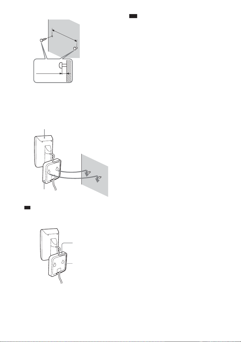
2 Fasten the screws to the wall.
For the front and surround speakers
330 mm
13 inch
(
8 to 10 mm
11
/32 to 13/32
(
inch
)
3 Hang the speakers on the screws.
4.6 mm
3
/16 inch)
(
10 mm
13
/32 inch)
(
When hanging both the IR transmitter and
surround speaker (L), adjust the position of the
IR transmitter after deciding the position of the
surround speaker (L).
1 Rotate the stand of the IR transmitter.
)
IR transmitter
Stand
2 Install 2 commercially available screws in
the wall so that it protrudes 4 mm (
Install the screws 30 mm (1
3
/16 inch).
3
/16 inch) apart.
continued
25
GB
Page 26
p
30 mm
(1 3/16 inch)
4 mm (3/16 inch)
3 Hang the IR transmitter via hole on the
bottom of the stand on the screw.
Make sure that the IR transmitter does not
move after installation.
IR transmitter
Note
• Use screws suitable for the material and strength of
the wall.
• Do not install the IR transmitter to a wall of low
strength.
• Sony is not lia ble for any damage or accident incurred
by incorrect installation (i.e. low strength wall, etc.),
incorrect use of this product, or natural disaster.
• When connecting/disconnecting the cord, detach the
IR transmitter from the wall first.
Stand
Ti
• You can store the cords in the troughs in the bottom
of the stand.
Stand
Troughs
GB
26
Page 27
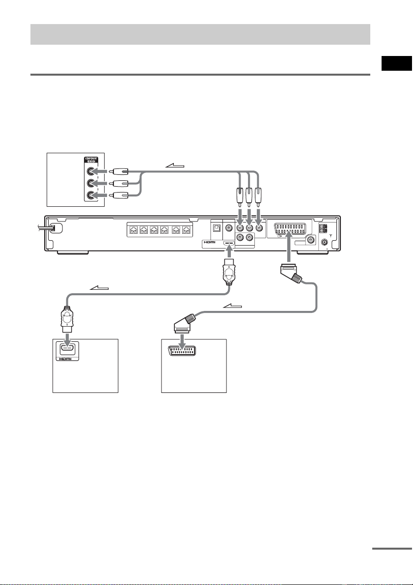
TV Hookup (Advanced)
Select a hookup suitable for the jacks on your TV.
Connecting the video/HDMI* cords
Sends a played back DVD image to a TV.
Check the jacks of your TV, and choose connection method A, B, or C. Picture quality improves in
order from A (standard) to C (HDMI).
TV with COMPONENT
B
VIDEO IN jacks
Y
PB/CB
PR/CR
LINE1 LINE2
DIGITAL IN
DIGITAL IN
OPTICAL
OUT
(DVD ONLY)
YPB/CBPR/C
COAXIAL
SPEAKER
FRONT R FRONT L SUR R SUR LCENTER WOOFER
To HDMI* OUT
COMPONENT VIDEO OUT
RLAUDIO IN
LINE1
R
(DVD ONLY)
To COMPONENT
VIDEO OUT
EURO AV
OUTPUT(TO TV)
DIR-T1
To EURO AV
T OUTPUT
(TO TV)
COAXIAL
FM
AM
75
Getting Started – ADVANCED –
C
IN
To HDMI* IN
To EURO AV INPUT
A
TV with HDMI* jack
* HDMI (high-definition multimedia interface)
The system is based on version 1.1 of High-Definition Multimedia Interface Specifications.
The system incorporates High-Definition Multimedia Interface (HDMITM) technology.
HDMI, the HDMI logo and High-Definition Multimedia Interface trademarks or registered trademarks of HDMI
Licensing LLC.
continued
27
GB
Page 28
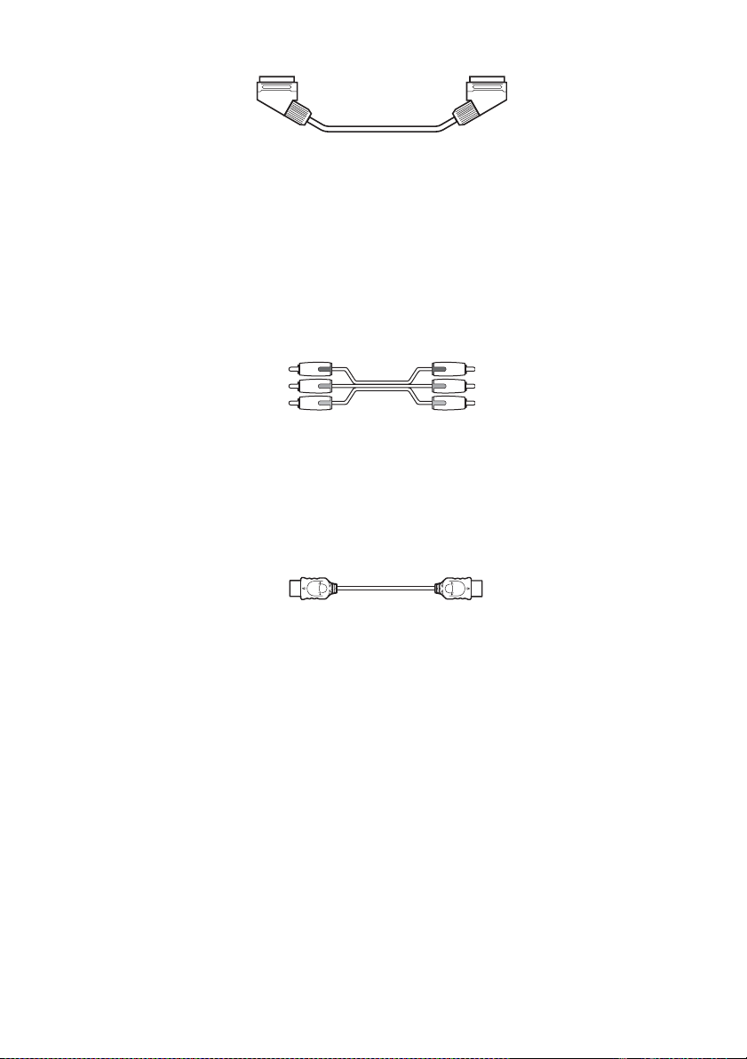
A To connect to a TV with the SCART (EURO AV) cord (not supplied)
.
Be sure to connect the SCART (EURO AV) cord to the EURO AV T OUTPUT (TO TV) jack on the
system.
When you connect using the SCART (EURO AV) cord, check that the TV conforms to S video or RGB
signals. If the TV conforms to S video, change the input mode of the TV to RGB signals. Refer to the
operating instructions supplied with the TV to be connected.
B To connect to a TV with the COMPONENT VIDEO IN jacks
Connect a component video cord (not supplied). To use the COMPONENT VIDEO OUT jacks (Y, PB/
C
B, PR/CR), your TV monitor must be equipped with via COMPONENT VIDEO IN jacks (Y,PB/CB,
P
R/CR). If your TV accepts progressive format signals, you must use this connection and set the output
channel of the system to progressive format (page 29).
Green
Blue
Red
C To connect to a TV with the HDMI (high-definition multimedia
interface)/DVI (digital visual interface) input jack
Use a certified HDMI (high-definition multimedia interface) cord (not supplied) to enjoy high quality
digital picture and sound through the HDMI OUT (high-definition multimedia interface out) jack.
Note that Super Audio CD sound is not output from the HDMI OUT (high-definition multimedia
interface out) jack.
To connect to a TV with DVI (digital visual interface) input
Use an HDMI (high-definition multimedia interface)-DVI (digital visual interface) converter cord (not
supplied) with an HDMI (high-definition multimedia interface)-DVI (digital visual interface) adaptor
(not supplied). The DVI (digital visual interface) jack will not accept any audio signals. Furthermore,
you cannot connect the HDMI OUT (high-definition multimedia interface out) jack to DVI (digital
visual interface) jacks that are not HDCP (high-bandwidth digital content protection) compliant (e.g.,
DVI (digital visual interface) jacks on PC displays).
When connecting to a standard 4:3 screen TV
Depending on the disc, the image may not fit your TV screen.
To change the aspect ratio, see page 80.
GB
28
Page 29
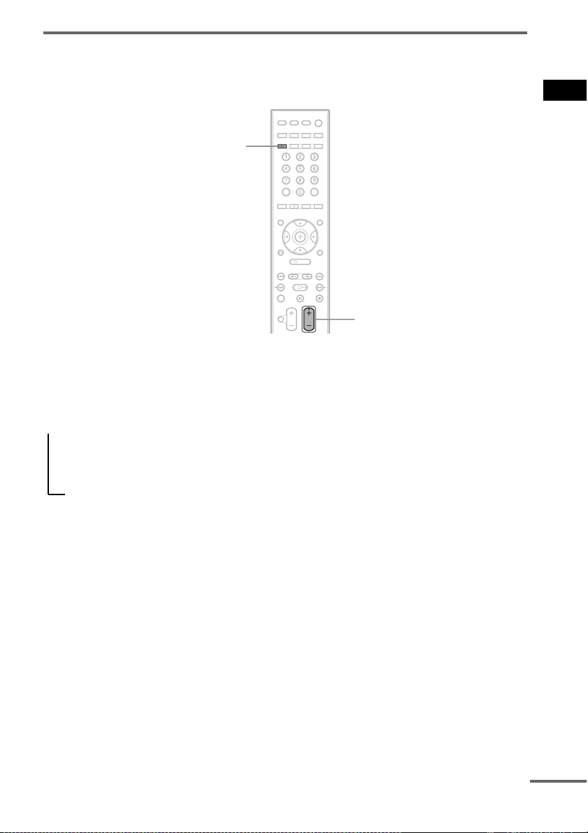
Does your TV accept progressive signals?
Progressive is the method for displaying TV images which reduces flickering, and sharpens the image.
To display using this method, you need to connect to a TV that accepts progressive signals.
PROGRESSIVE
FUNCTION +/–
“PROGRE” lights up in the front panel display when the system outputs progressive signals.
1 Press FUNCTION +/– repeatedly to select “DVD.”
2 Press PROGRESSIVE.
Each time you press PROGRESSIVE, the display changes as follows:
t P AUTO (PROGRESSIVE AUTO)
r
P VIDEO (PROGRESSIVE VIDEO)
r
INTERLACE
Getting Started – ADVANCED –
x P AUTO (PROGRESSIVE AUTO)
Select this setting when:
– your TV accepts progressive signals, and,
– the TV is connected to the COMPONENT VIDEO OUT jacks.
Normally select this under the above condition. This automatically detects the software type, and
selects the appropriate conversion method.
Note that the picture will not be clear or no picture will appear if you select these settings when
either of the above conditions are not met.
x P VIDEO (PROGRESSIVE VIDEO)
Select this setting when:
– your TV accepts progressive signals, and,
– the TV is connected to the COMPONENT VIDEO OUT jacks, and,
– you want to fix the conversion method to PROGRESSIVE VIDEO for video-based software.
Select this if the image is not clear when you select PROGRESSIVE AUTO.
Note that the picture will not be clear or no picture will appear if you select these settings when
either of the above conditions are not met.
continued
29
GB
Page 30

x INTERLACE
Select this setting when:
– your TV does not accept progressive signals, or,
– your TV is connected to jacks other than the COMPONENT VIDEO OUT jacks (EURO AV
T OUTPUT (TO TV)).
You cannot select NORMAL (INTERLACE) while “HDMI” lights up in the front panel display.
About DVD software types and the conversion method
DVD software can be divided into 2 types: film-based software and video-based software.
Video-based software is derived from TV, such as dramas and sit-coms, and displays images at 30
frames/60 fields per second. Film-based software is derived from film and displays images at 24 frames
per second. Some DVD software contains both video and film.
In order for these images to appear natural on your screen when output in progressive format, the
progressive signals need to be converted to match the type of DVD software that you are watching.
Note
• When you play video-based software in progressive signal format, sections of some types of images may appear
unnatural due to the conversion process when output through the COMPONENT VIDEO OUT jacks. Even though
you set to “PROGRESSIVE AUTO” or “PROGRES SIVE VIDEO,” images from the EURO AV T OUTPUT (TO
TV) jack are unaffected as they are output in the interlace format.
• If you set [LINE] in [SCREEN SETUP] to [RGB] (page 81), the system switches to “INTERLACE.” This will
happen even though you select “PROGRESSIVE AUTO” or “PROGRESSIVE VIDEO.”
• If you set [LINE] in [SCREEN SETUP] to [RGB] (page 81), the system outputs no component video signals.
30
GB
Page 31

Other Component Hookup
You can enjoy sound using the speakers of this system by connecting the AUDIO OUT jacks of another
component. For video connection of other components, connect directly to the TV.
Connecting the system and the other component
Outputs the other component through the speakers of this system.
VCR, digital satellite receiver
or PlayStation 2, etc.
COAXIAL
DIGITAL
OUT
To LINE2 (DIGITAL IN
COAXIAL)
COMPONENT VIDEO OUT
SPEAKER
FRONT R FRONT L SUR R SUR LCENTER WOOFER
LINE1 LINE2
DIGITAL IN
OPTICAL
OUT
(DVD ONLY)
DIGITAL IN
COAXIAL
YPB/CBPR/C
RLAUDIO IN
LINE1
R
(DVD ONLY)
EURO AV
OUTPUT(TO TV)
DIR-T1
COAXIAL
AM
FM
75
Getting Started – ADVANCED –
To LINE1 (DIGITAL IN
To LINE1 (AUDIO IN)
OPTICAL)
OPTICAL
DIGITAL
OUT
AUDIO
OUT
L
R
VCR, digital satellite receiver
or PlayStation 2, etc.
To connect the AUDIO OUT jacks of other component to the LINE1
(AUDIO IN) jacks of this system
Connect the VCR or other components to the LINE1 (AUDIO IN) jacks using the audio cord (not
supplied). When connecting a cord, be sure to match the color-coded sleeves to the appropriate jacks
on the components.
White (L/audio)
Red (R/audio)
To listen to the portable audio source sound through the system
Connect the audio output jacks of the portable audio source to the AUDIO IN jack on the front panel
of the system with the stereo mini-plug cord (not supplied).
continued
31
GB
Page 32

Ti
p
• When listening to MP3 format recordings using a portable audio source, you can enhance the sound.
Press FUNCTION +/- to select “AUDIO.” Connect the portable audio source. Press SOUND FIELD repeatedly
until “A.F.D. STD” appears in the front panel display.
To cancel, select other than “A.F.D. STD.”
If you connect a digital satellite receiver with an DIGITAL OUT
(OPTICAL or COAXIAL) jack
The digital satellite receiver can be connected to the LINE1 (DIGITAL IN OPTICAL) jack or LINE2
(DIGITAL IN COAXIAL) jack instead of the LINE1 (AUDIO IN) jacks of the system.
The system can accept both the digital and analog signals. Digital signals have priority over analog
signals. If the digital signal ceases, the analog signal will be processed after 2 seconds.
If you connect a digital satellite receiver without an DIGITAL OUT jack
Connect the digital satellite receiver to the LINE1 jacks only of the system.
Note
• Be sure to make connections securely to avoid hum and noise.
GB
32
Page 33

Basic Operations
Playing Discs
4 Press A.
5 Load a disc.
Place one disc on the tray, and then press A.
Basic Operations
"/1
/
DISC SKIP
MUTING
VOLUME
+/–
Disc tray
X
A
H
FUNCTION
Adjust the
volume
Connect
headphones
"/1
./>
H
x
FUNCTION
+/–
Depending on the DVD VIDEO or VIDEO CD,
some operations may be different or restricted.
Refer to the operation details supplied with your
disc.
1 Turn on your TV.
2 Switch the input selector on the TV to
this system.
3 Press "/1.
The system turns on.
Unless the system is set to “DVD,” press
FUNCTION +/– to select “DVD.”
When you play an 8 cm disc, place it on the
inner circle of the tray. Be careful that the disc
is not skewed on the inner circle of the tray.
Note
• Do not forcibly press the disc tray closed with
your finger, as this may cause malfunction.
• Do not place more than one disc on the tray.
6 Press H.
The system starts playback (continuous
play).
Adjust the volume on the system.
The volume level appears on the TV screen
and in the front panel display.
Note
• Depending on the system status, the volume level
may not appear on the TV screen.
To save the power in standby
mode
Press "/1 while the system turns on. To cancel
standby mode, press "/1 once.
Additional operations
To Press
Stop x
Pause X
Resume play after pause X or H
Go to the next chapter,
track, or scene
Go back to the preceding
chapter, track, or scene
Mute the sound MUTING. To cancel
> (except for JPEG)
. (except for JPEG)
muting, press it again
or VOLUME + to
adjust the sound
volume.
continued
33
GB
Page 34

To Press
Stop play and remove the
disc
Replay the previous scene* (instant replay)
Briefly fast forward the
current scene**
* DVD VIDEOs/DVD-RWs/DVD-Rs only. The
button can be used except for DivX video files.
** DVD VIDEOs/DVD-RWs/DVD-Rs/DVD+RWs/
DVD+Rs only. The button can be used except for
DivX video files.
Note
• You may not be able to use the Instant Replay or
Basic Operations
Instant Advance function with some scenes.
A
during playback.
(instant advance)
during playback.
Enjoying the Radio or Other Components
X/x/c,
AMP MENU
FUNCTION
+/–
Selecting the connected component
You can use a VCR or other components
connected to the LINE 1 jacks on the rear panel.
Refer to the operation manual supplied with the
components for further information on the
operation.
Press FUNCTION +/– repeatedly until
“LINE1” appears in the front panel display.
Each time you press FUNCTION +/–, the mode
of the system changes in the following sequence.
34
DVD t TUNER FM t TUNER AM t
LINE1 t LINE2 t TV t AUDIO t …
Note
• When you use both the LINE 1 (AUDIO IN) jacks
(analog connection) and LINE 1 (DIGITAL IN
OPTICAL) jack (digital connection) at the same time,
the digital connection takes priority.
GB
Page 35

Changing the input level of the sound from connected components
Distortion may occur when listening to a
component connected to the LINE 1 jacks on the
rear of the unit or to the AUDIO IN jack on the
front panel. This is not a malfunction and will
depend on the component connected.
To prevent this, you can change the input level
from the sound of the other components.
1 Press FUNCTION +/– repeatedly until
“LINE1” or “AUDIO” appears in the
front panel display.
2 Press AMP MENU.
3 Press X/x repeatedly until
“ATTENUATE” appears in the front
panel display, then press or c.
4 Press X/x to select a setting.
• ATT ON: attenuates the input level. The
output level is changed.
• ATT OFF: normal input level.
5 Press .
The setting is reflected.
6 Press AMP MENU.
The AMP menu turns off.
Enjoying TV or VCR Sound from All Speakers
You can enjoy TV or VCR sound from all the
speakers in this system.
For details, see “TV Hookup (Advanced)”
(page 27) and “Other Component Hookup”
(page 31).
SOUND
FIELD
FUNCTION
+/–
1 Press FUNCTION +/– repeatedly until
“LINE1,” “LINE2,” or “TV” appears in
the front panel display.
2 Press SOUND FIELD repeatedly until
the sound field you want appears in the
front panel display.
When you want to output the TV sound or
stereo sound of a 2 channel source from the
6 speakers, select the “PRO LOGIC,” “PLII
MOVIE,” or “PLII MUSIC” sound field.
For details of sound field, see page 37.
Note
• When you use both the LINE 1 (AUDIO IN) jacks
(analog connection) and LINE 1 (DIGITAL IN
OPTICAL) jack (digital connection) at the same time,
the digital connection takes priority.
Basic Operations
35
GB
Page 36

p
Selecting the Movie or Music Mode
You can choose a suitable sound mode for
movies or music.
MOVIE/
MUSIC
Basic Operations
Press MOVIE/MUSIC during playback.
Press MOVIE/MUSIC repeatedly until the
mode you want lights up in the front panel
display. The default setting is underlined.
• AUTO
: selects the mode automatically to
produce the sound effect depending on the
disc.
• MOVIE: provides the sound for movies.
• MUSIC: provides the sound for music.
Ti
• When the movie or music mode is selected,
“MOVIE” or “MUSIC” is displaye d in the front panel
display.
GB
36
Page 37

Sound Adjustments
Enjoying Surround Sound by Using Sound Field
You can take advantage of surround sound
simply by selecting one of system’s preprogrammed sound fields. They bring the
exciting and powerful sound of movie theaters
into your home.
SOUND
FIELD
Sound field Display
2 CHANNEL STEREO 2CH STEREO
HEADPHONE THEATER HP THEATER
HEADPHONE
2 CHANNEL STEREO
* Use DCS Technology
HP 2CH
Automatic outputting of the original sound
x AUTO FORMAT DIRECT STANDARD
The auto decoding function automatically
detects the type of audio signal being input
(Dolby Digital, DTS, or standard 2 channel
stereo) and performs the proper decoding if
necessary. This mode presents the sound as it
was recorded/encoded, without adding any
effects (e.g. reverberation).
However, if there are no low frequency signals
(Dolby Digital LFE, etc.), it will generate a low
frequency signal for output to the subwoofer.
Outputting the sound from multiple speakers
x AUTO FORMAT DIRECT MULTI
This mode lets you enjoy audio playback of all
types of discs from multiple speakers.
Sound Adjustments
Press SOUND FIELD.
Press SOUND FIELD repeatedly until the sound
field you want appears in the front panel display.
All sound field
Sound field Display
AUTO FORMAT DIRECT
STANDARD
AUTO FORMAT DIRECT
MULTI
Dolby Pro Logic PRO LOGIC
Dolby Pro Logic II MOVIE PLII MOVIE
Dolby Pro Logic II MUSIC PLII MUSIC
CINEMA STUDIO EX A C. ST. EX A*
CINEMA STUDIO EX B C. ST. EX B*
CINEMA STUDIO EX C C. ST. EX C*
A.F.D. STD
A.F.D. MULTI
Outputting 2 channel sources like CDs by 5.1channel
x Dolby Pro Logic
Dolby Pro Logic produces five output channels
from 2 channel sources. This mode performs Pro
Logic decoding to the input signal and output to
front, center, and surround speakers.
Meanwhile, the surround channel becomes
monaural.
x Dolby Pro Logic II MOVIE/MUSIC
Dolby Pro Logic II produces five full-bandwidth
output channels from 2 channel sources. This is
done using an advanced, high-purity matrix
surround decoder that extracts the spatial
properties of the original recording without
adding any new sounds or tonal colorations.
continued
37
GB
Page 38

Note
• When the input signal is multi channel source, Dolby
Pro Logic and Dolby Pro Logic II MOVIE/MUSIC
are canceled and the multi channel source is output
directly.
• When the bilingual broadcast sound is input, Dolby
Pro Logic and Dolby Pro Logic II MOVIE/MUSIC
are not effective.
Enjoying Digital Cinema Sound
About DCS (Digital Cinema
Sound)
In collaboration with Sony Pictures
Entertainment, Sony measured the sound
environment of their studios and integrated the
data of the measurement and Sony’s own DSP
(Digital Signal Processor) technology to
develop “Digital Cinema Sound.” “Digital
Cinema Sound” simulates in a home theater an
ideal movie theater sound environment based on
the preference of the movie director.
x CINEMA STUDIO EX A (Cinema Studio
EX A)
Reproduces the sound characteristics of the
Sony Pictures Entertainment “Cary Grant
Theater” cinema production studio. This is a
standard mode, great for watching most any type
of movie.
x CINEMA STUDIO EX B (Cinema Studio
EX B)
Reproduces the sound characteristics of the
Sony Pictures Entertainment “Kim Novak
Theater” cinema production studio. This mode
is ideal for watching science-fiction or action
movies with lots of sound effects.
x CINEMA STUDIO EX C (Cinema Studio
EX C)
Reproduces the sound characteristics of the
Sony Pictures Entertainment scoring stage. This
mode is ideal for watching musicals or classic
films where music is featured in the soundtrack.
About Cinema Studio EX
Cinema Studio EX is ideal for enjoying the
movie software encoded with multi channel
format, such as the Dolby Digital DVD. This
mode reproduces the sound characteristics of
Sony Pictures Entertainment’s studios.
Cinema Studio EX consists of the following 3
elements.
• Virtual Multi Dimension
Creates 5 sets of virtual speakers surrounding
the listener from a single pair of actual
surround speakers.
• Screen Depth Matching
In a movie theater, sound seems to come from
inside the image reflected on the movie screen.
This element creates the same sensation in
your listening room by shifting the sound of
the front speakers “into” the screen.
• Cinema Studio Reverberation
Reproduces the reverberations peculiar to a
movie theater. Cinema Studio EX is the
integrated mode which operates these
elements simultaneously.
Note
• The virtual speaker effect may cause increased noise
in the playback signal.
• When listening with sound fields that employ virtual
speakers, you will not be able to hear any sound
coming directly from the surround speakers.
Using only the front speaker and subwoofer
x 2 CHANNEL STEREO
This mode outputs the sound from the front left
and right speakers and subwoofer. Standard 2
channel (stereo) sources completely bypass the
sound field processing. Multi channel surround
formats are downmixed to two channels.
This allows you to play any source using only
the front left and right speakers and subwoofer.
Enjoying the surround sound by headphones
x HEADPHONE THEATER
This mode outputs the sound as surround from
headphone L/R.
x HEADPHONE 2 CHANNEL STEREO
This mode outputs the sound from headphone L/
R. Standard 2 channel (stereo) sources
completely bypass the sound field processing.
38
GB
Page 39

Multi channel surround formats are downmixed
p
to two channels.
To turn the surround effect off
Press SOUND FIELD repeatedly until “A.F.D.
STD” or “2CH STEREO” appears in the front
panel display.
Ti
• The system memorizes the last sound field selected
for each function mode.
Whenever you select a function such as DVD or
TUNER, the sound field that was last applied to
function is automatically applied again. For example,
if you listen to DVD with PRO LOGIC as the sound
field, then change to a nother function, and then return
to DVD, PRO LOGIC will be applied again.
Enjoying Multiplex Broadcast Sound
(DUAL MONO)
You can enjoy multiplex broadcast sound when
the system receive the Dolby Digital multiplex
broadcast signal.
Note
• To receive the Dolby Digital signal, you need to
connect a digital satellite tuner to the system with an
optical cable (page 31) and set the digital output
mode of the digital satellite tuner to Dolby Digital.
AUDIO
Sound Adjustments
Press AUDIO.
Press AUDIO repeatedly until the signal you
want appears in the front panel display. The
default setting is underlined.
•MAIN
: Sound of the main language will be
output.
• SUB: Sound of the sub language will be
output.
• MAIN+SUB: Mixed sound of both the main
and sub languages will be output.
GB
39
Page 40

With each press, playback speed becomes faster.
Various Functions for Playing Discs
Searching for a Particular Point on a Disc
(Scan, Slow-motion Play, Freeze
Frame)
You can quickly locate a particular point on a
disc by monitoring the picture or playing back
slowly.
Note
• Depending on the DVD/DivX video/VIDEO CD, you
may not be able to do some of the operations
described.
Locating a point quickly by playing a disc in fast forward or fast reverse (Scan)
(except for JPEG)
Press /m or M/ while playing a disc.
When you find the point you want, press H to
return to normal speed. Each time you press /
m or M/ during scan, the playback speed
changes. With each press the indication changes
as shown below. Actual speeds may differ with
some discs.
Playback direction
Watching frame by frame (Slow-motion Play)
(DVD VIDEO, DVD-R, DVD-RW, DivX
video, VIDEO CD only)
Press /m or M/ when the system is in
pause mode. To return to the normal playback
speed, press H. Each time you press /m or
M/ during Slow-motion Play, the playback
speed changes. Two speeds are available. With
each press the indication changes as follows:
Playback direction
2 y 1
Opposite direction (DVD VIDEO only)
2 y 1
Playing one frame at a time (Freeze Frame)
(except for Super Audio CD, CD, MP3,
and JPEG)
When the system is in the pause mode, press
(step) to go to the next frame. Press (step) to
go to the preceding frame (DVD VIDEO/DVDR/DVD-RW only). To return to normal
playback, press H.
Note
• You cannot search for a still picture on a DVD-R/
DVD-RW in VR mode.
• For DATA CDs/DATA DVDs, this function works
only for DivX video files.
× 2B t 1M t 2M t 3M
3M (DVD VIDEO/DVD-VR mode/DivX video/
VIDEO CD only)
× 2B (DVD VIDEO/Super Audio CD/CD only)
Opposite direction
× 2b t 1m t 2m t 3m
3m (DVD VIDEO/DVD-VR mode/DivX video/
VIDEO CD only)
× 2b (DVD VIDEO only)
GB
40
Page 41

Searching for a Title/ Chapter/Track/Scene, etc.
You can search a DVD by title or chapter, and
you can search a VIDEO CD/Super Audio CD/
CD/DATA CD/DATA DVD by track, index, or
scene. As titles and tracks are assigned unique
numbers on the disc, you can select the desired
one by entering its number. Or, you can search
for a scene using the time code.
1 Press DISPLAY. (When playing a
DATA CD/DATA DVD with JPEG image
files, press DISPLAY twice.)
The Control Menu appears.
2 Press X/x to select the search method.
The display will show different items
depending on the disc.
[TITLE], [TRACK], [SCENE]
[CHAPTER], [INDEX]
[TIME/TEXT]
Select [TIME/TEXT] to search for a
starting point by inputting the time code.
[TRACK]
[INDEX]
[ALBUM]
[FILE]
Example: when you select
[CHAPTER]
[** (**)] is selected (** refers to a number).
The number in parentheses indicates the
total number of titles, chapters, tracks,
indexes, scenes, albums or files.
)
1 2 ( 2 7
)
1 8 ( 3 4
T
1 : 3 2 : 5 5
Selected row
DVD VIDEO
3 Press .
[** (**)] changes to [– – (**)].
)
1 2 ( 2 7
)
( 3 4
T
1 : 3 2 : 5 5
DVD VIDEO
4 Press X/x or the number buttons to
select the title, chapter, track, index,
scene, etc., number you want to search
for.
If you make a mistake
Cancel the number by pressing CLEAR,
then select another number.
5 Press .
The system starts playback from the
selected number.
To search for a scene using the
time code (DVD VIDEO and
DVD-VR mode only)
1 In Step 2, select [TIME/TEXT].
[T **:**:**] (playing time of the current title)
is selected.
2 Press .
[T **:**:**] changes to [T --:--:--].
3 Input the time code using the number
buttons, then press .
For example, to find the scene at 2 hours, 10
minutes, and 20 seconds after the beginning,
just enter [2:10:20].
Various Functions for Playing Discs
continued
41
GB
Page 42

Ti
p
• When the Con trol Menu display is turned off, you can
search for a chapter (DVD VIDEO/DVD-R/DVDRW), track (VIDEO CD/Super Audio CD/CD), or
file (DATA CD/DATA DVD (DivX video)) by
pressing the number buttons and .
Note
• You cannot search for a scene on a DVD+RW/
DVD+R using the time code.
Searching by Scene
(Picture Navigation)
You can divide the screen into 9 subscreens and
find the desired scene quickly.
1 Press PICTURE NAVI during playback.
The following display appears.
CHAPTER VIEWER
ENTER
2 Press PICTURE NAVI repeatedly to
select an item.
• [TITLE VIEWER] (DVD VIDEO only)
• [CHAPTER VIEWER] (DVD VIDEO
only)
• [TRACK VIEWER] (VIDEO CD/
Super VCD only)
3 Press .
The first scene of each title, chapter, or
track appears as follows.
1
4
7
2
5
8
3
6
9
4 Press C/X/x/c to select a title, chapter,
or track, and press .
Playback starts from the selected scene.
To return to normal play during
setting
Press O RETURN or DISPLAY.
Note
• Depending on the disc, you may not be able to select
some items.
GB
42
Page 43

p
p
Resuming Playback from the Point Where You Stopped the Disc
(Resume Play)
When you stop the disc, the system remembers
the point where you pressed x and “RESUME”
appears in the front panel display. As long as
you do not remove the disc, Resume Play will
work even if the system enters standby mode by
pressing "/1.
1 While playing a disc, press x to stop
playback.
“RESUME” appears in the front panel
display.
If “RESUME” does not appear, Resume
Play is not available.
2 Press H.
The system starts playback from the point
where you stopped the disc in Step 1.
Note
• Depending on where you stop the disc, the system
may not resume playback from exactly the same
point.
• The point where you stopped playing may be cleared
when:
– you eject the disc.
– the system enters standby mode (DATA CD/
DATA DVD only).
– you change or reset the settings on the Setup
Display.
– you change the function by pressing FUNCTION
+/–.
– you disconnect the AC power cord (mains lead).
• For DVD-Rs/DVD-RWs in VR mode, VIDEO CDs,
CDs, Super Audio CDs, DATA CDs, and DATA
DVDs, the system remembers the resume playback
point for the current disc.
• Resume Play does not work during Program Play and
Shuffle Play.
• This function may not work properly with some
discs.
Ti
• To play from the be ginning of the disc, press x twice,
then press H.
To enjoy a disc that is played
before by resume playback
(Multi-disc Resume)
(DVD VIDEO, VIDEO CD only)
This system stores the point where you stopped
the disc for up to 40 discs and resumes playback
the next time you insert the same disc. If you
store a resume playback point for the 41st disc,
the resume playback point for the first disc is
deleted.
To activate this function, set [MULTI-DISC
RESUME] in [CUSTOM SETUP] to [ON]. For
details, see “[MULTI-DISC RESUME] (DVD
VIDEO/VIDEO CD only)” (page 82).
Ti
• To play from the be ginning of the disc, press x twice,
then press H.
Note
• If [MULTI-DISC RESUME] in [CUSTOM SETUP]
is set to [OFF] (page 82), the resume point is cleared
when you change the function by pressing
FUNCTION +/–.
Various Functions for Playing Discs
GB
43
Page 44

Creating Your Own Program
(Program Play)
You can play the contents of a disc in the order
you want by arranging the order of the tracks on
the disc to create your own program. You can
program up to 99 tracks.
1 Press DISPLAY.
The Control Menu appears.
2 Press X/x to select
[PROGRAM], then press .
The options for [PROGRAM] appear.
T
OFF
OFF
SET
ON
6 (14)
2 : 5 0
PLAY
CD
PROGRAM
ALL CLEAR
1. TRACK
2. TRACK
3. TRACK
4. TRACK
5. TRACK
6. TRACK
7. TRACK
– –
– –
– –
– –
– –
– –
– –
0:00:00
T
– –
01
02
03
04
05
06
5 Select the track you want to program.
For example, select track [02].
Press X/x to select [02] under [T], then
press . The track number may be
displayed in 3 digits for a Super Audio CD.
Selected track
– –
– –
– –
– –
– –
– –
0:15:30
T
– –
01
02
03
04
05
06
PROGRAM
ALL CLEAR
1. TRACK 0 2
2. TRACK
3. TRACK
4. TRACK
5. TRACK
6. TRACK
7. TRACK
Total time of the programmed tracks
3 Press X/x to select [SET t], then
press .
[TRACK] is displayed when you play a
VIDEO CD, Super Audio CD, or CD.
PROGRAM
ALL CLEAR
1. TRACK
– –
2. TRACK
– –
3. TRACK
– –
4. TRACK
– –
5. TRACK
– –
6. TRACK
– –
7. TRACK
Tracks recorded
on a disc
Total time of the
programmed tracks
4 Press c.
The cursor moves to the track row [T] (in
this case, [01]).
GB
44
0:00:00
T
– –
01
02
03
04
05
06
6 To program other tracks, repeat steps 4
to 5.
The programmed tracks are displayed in the
selected order.
7 Press H to start Program Play.
Program Play starts.
When the program ends, you can restart the
same program again by pressing H.
To return to normal play
Press CLEAR, or select [OFF] in Step 3. To play
the same program again, select [ON] in Step 3
and press .
To turn off the Control Menu
Press DISPLAY repeatedly until the Control
Menu is turned off.
Page 45

To change or cancel a program
1 Follow steps 1 to 3 of “Creating Your Own
Program.”
2 Select the program number of the track you
want to change or cancel using X/x. If you
want to delete the track from the program,
press CLEAR.
3 Follow Step 5 for new programming. To
cancel a program, select [--] under [T], then
press .
To cancel all of the tracks in the
programmed order
1 Follow steps 1 to 3 of “Creating Your Own
Program.”
2 Press X and select [ALL CLEAR].
3 Press .
Playing in Random Order
(Shuffle Play)
You can have the system “shuffle” tracks.
Subsequent “shuffling” may produce a different
playing order.
Note
• Same song may be played repeatedly during MP3
playback.
1 Press DISPLAY during playback.
The Control Menu appears.
2 Press X/x to select [SHUFFLE],
then press .
The options for [SHUFFLE] appear.
T
OFF
OFF
TRACK
6 (14)
2 : 5 0
PLAY
CD
3 Press X/x to select the item to be
shuffled.
x When playing a VIDEO CD, Super
Audio CD, or CD
• [TRACK]: shuffles tracks on the disc.
x When Program Play is activated
• [ON]: shuffles tracks selected in Program
Play.
x When playing a DATA CD (except for
DivX) or DATA DVD (except for DivX)
• [ON]: shuffles MP3 audio tracks in the
album on the current disc. When no album
is selected, the first album will play in
random order.
Note
• A track already played is also selected in
random order.
4 Press .
Shuffle Play starts.
Various Functions for Playing Discs
continued
45
GB
Page 46

To return to normal play
Press CLEAR, or select [OFF] in Step 3.
To turn off the Control Menu
Press DISPLAY repeatedly until the Control
Menu is turned off.
Note
• You cannot use this function with VIDEO CDs and
Super VCDs with PBC playback.
Playing Repeatedly
(Repeat Play)
You can play all the titles, tracks or albums on a
disc or a single title, chapter, track, or album
repeatedly.
You can use a combination of Shuffle or
Program Play modes.
1 Press DISPLAY during playback.
The Control Menu appears.
2 Press X/x to select [REPEAT],
then press .
The options for [REPEAT] appear.
T
OFF
OFF
DISC
TRACK
6 (14)
2 : 5 0
PLAY
CD
3 Press X/x to select the item to be
repeated.
The default setting is underlined.
x When playing a DVD VIDEO or DVDVR
•[OFF]: does not play repeatedly.
• [DISC]: repeats all of the titles on the disc.
• [TITLE]: repeats the current title on a
disc.
• [CHAPTER]: repeats the current chapter.
x When playing a VIDEO CD, Super
Audio CD, or CD
•[OFF]: does not play repeatedly.
• [DISC]: repeats all of the tracks on the
disc.
• [TRACK]: repeats the current track.
x When playing a DATA CD or DATA
DVD
•[OFF]: does not play repeatedly.
• [DISC]: repeats all of the albums on the
disc.
46
GB
Page 47

• [ALBUM]: repeats the current album.
• [TRACK] (MP3 audio tracks only):
repeats the current track.
• [FILE] (DivX video files only): repeats
the current file.
4 Press .
The item is selected.
To return to normal play, press CLEAR, or
select [OFF] in Step 3.
To turn off the Control Menu
Press DISPLAY repeatedly until the Control
Menu is turned off.
Note
• You cannot use this function with VIDEO CDs and
Super VCDs with PBC playback.
• When playing a DATA CD/DATA DVD which
contains MP3 audio track and JPEG image files, and
their playing time are not the same, the audio sound
will not match the image.
• When [MODE (MP3, JPEG)] is set to [IMAGE
(JPEG)] (page 59), you cannot select [TRACK].
Using the DVD’s Menu
A DVD is divided into a lot of sections, which
make up a picture or music feature. These
sections are called “titles.” When you play a
DVD which contains several titles, you can
select the title you want using TOP MENU.
When you play DVDs that allow you to select
items such as the language for the subtitles and
the language for the sound, select these items
using MENU.
1 Press TOP MENU or MENU.
The disc’s menu appears on the TV screen.
The contents of the menu vary from disc to
disc.
2 Press C/X/x/c or the number buttons to
select the item you want to play or
change.
3 Press .
Various Functions for Playing Discs
47
GB
Page 48

Changing the Sound
When playing a DVD VIDEO or DATA CD/
DATA DVD (DivX video files) recorded in
multiple audio formats (PCM, Dolby Digital,
MPEG audio, or DTS), you can change the
audio format. If the DVD VIDEO is recorded
with multilingual tracks, you can also change the
language.
With VIDEO CDs, CDs, DATA CDs, or DATA
DVDs, you can select the sound from the right or
left channel and listen to the sound of the
selected channel through both the right and left
speakers.
1 Press AUDIO during playback.
The following display appears.
1:ENGLISH DOLBY DIGITAL 3/2.1
2 Press AUDIO repeatedly to select the
desired audio signal.
x When playing a DVD VIDEO
Depending on the DVD VIDEO, the choice
of language varies.
When 4 digits are displayed, they indicate a
language code. Refer to “Language Code
List” (page 98) to see which language the
code represents. When the same language is
displayed two or more times, the DVD
VIDEO is recorded in multiple audio
formats.
x When playing a DVD-VR
The types of sound tracks recorded on a disc
are displayed. The default setting is
underlined.
Example:
•[1: MAIN]
• [1: SUB] (sub sound)
• [1: MAIN+SUB] (main and sub sound)
•[2: MAIN]
•[2: SUB]
(main sound)
•[2: MAIN+SUB]
Note
• [2: MAIN], [2: SUB], and [2: MAIN+SUB] do
not appear when one audio stream is r ecorded on
the disc.
x When playing a VIDEO CD, CD, DATA
CD (MP3 audio), or DATA DVD (MP3
audio)
The default setting is underlined.
• [STEREO]
: the standard stereo sound
• [1/L]: the sound of the left channel
(monaural)
• [2/R]: the sound of the right channel
(monaural)
x When playing a DATA CD (DivX
video) or DATA DVD (DivX video)
The choice of DATA CD or DATA DVD
audio signal formats differ, depending on
the DivX video file contained on the disc.
The format is shown in the display.
x When playing a Super VCD
The default setting is underlined.
• [1:STEREO]
: the stereo sound of the
audio track 1
• [1:1/L]: the sound of the left channel of
the audio track 1 (monaural)
• [1:2/R]: the sound of the right channel of
the audio track 1 (monaural)
• [2:STEREO]: the stereo sound of the
audio track 2
• [2:1/L]: the sound of the left channel of
the audio track 2 (monaural)
• [2:2/R]: the sound of the right channel of
the audio track 2 (monaural)
Note
• While playing a Super VCD on which the audio track
2 is not recorded, no sound will come out when you
select [2:STEREO], [2:1/L], or [2:2/R].
• You cannot change the sound for Super Audio CDs.
48
GB
Page 49

Checking the audio signal format
(DVD, DivX video only)
If you press AUDIO repeatedly during
playback, the format of the current audio signal
(PCM, Dolby Digital, DTS, etc.) appears as
shown below.
x When playing a DVD
Example:
Dolby Digital 5.1 ch
LFE (Low
Surround (L/R)
Frequency Effect)
About audio signals
Audio signals recorded in a disc contain the
sound elements (channels) shown below. Each
channel is output from a separate speaker.
• Front (L)
• Front (R)
•Center
• Surround (L)
• Surround (R)
• Surround (Monaural): This signal can be either
the Dolby Surround Sound processed signals
or the Dolby Digital sound’s monaural
Surround audio signals.
• LFE (Low Frequency Effect) signal
Various Functions for Playing Discs
1:ENGLISH DOLBY DIGITAL
Front (L/R) +
Center
Currently playing
program format
3 / 2 .1
LRC
LFE
LS RS
Example:
Dolby Digital 3 ch
Surround
Front (L/R)
2:SPANISH DOLBY DIGITAL
(Monaural)
2 / 1
LR
S
Currently playing
program format
x When playing a DATA CD (DivX video) or
DATA DVD (DivX video)
Example:
MP3 audio
1: MP3 128k
Bit rate
49
GB
Page 50

Selecting [ORIGINAL] or
Viewing Information About
[PLAY LIST] on a DVD-R/
DVD-RW
Some DVD-Rs/DVD-RWs in VR (Video
Recording) mode have two types of titles for
playback: originally recorded titles
([ORIGINAL]) and titles that can be created on
recordable DVD players for editing ([PLAY
LIST]). You can select the type of title to be
played.
1 Press DISPLAY when the system is
in stop mode.
The Control Menu appears.
2 Press X/x to select [ORIGINAL/
PLAY LIST], then press .
The options for [ORIGINAL/PLAY LIST]
appear.
)
1 ( 4 4
(
3
2 8
T
1 : 3 0 : 5 0
PLAY LIST
PLAY LIST
ORIGINAL
)
DVD-VR
3 Press X/x to select a setting.
The default setting is underlined.
• [PLAY LIST]
from [ORIGINAL] for editing.
• [ORIGINAL]: plays the titles originally
recorded.
: plays the titles created
4 Press .
the Disc
Viewing the playing time and remaining time in the front panel display
You can check disc information, such as the
remaining time, total number of titles in a DVD,
tracks in a VIDEO CD, Super Audio CD, CD, or
MP3, file name of a DivX video using the front
panel display (page 100).
Press DISPLAY.
Each time you press DISPLAY while playing
the disc, the display changes 1 t 2 t ...
t 1 t ...
Some displayed items may disappear after a few
seconds.
When playing a DVD VIDEO or
DVD-R/DVD-RW
1 Playing time and number of the current title
2 Remaining time of the current title
3 Playing time and number of the current
chapter
4 Remaining time of the current chapter
5 Disc name
6 Title and chapter
When playing a DATA CD (DivX
video) or DATA DVD (DivX video)
1 Playing time of the current file
2 Current file name
3 Current album and file number
When playing a VIDEO CD
(without PBC functions), Super
Audio CD, or CD
1 Playing time of the current track
2 Remaining time of the current track
3 Playing time of the disc
4 Remaining time of the disc
5 Disc name
6 Track and index*
50
GB
Page 51

* VIDEO CD only.
p
When playing a DATA CD (MP3
audio) or DATA DVD (MP3 audio)
1 Playing time and current track number
2 Track (file) name
Ti
• When playing VIDEO CDs with PBC functions, the
playing time is displayed.
Note
• The system can only display the first level of the
DVD/CD text, such as the Disc name or title.
• If an MP3 file name cannot be displayed, “*” will
appear in the front panel display instead.
• The disc name or track name may not be displayed
depending on the text.
• Playing time of MP3 audio tracks and DivX video
files may not be displayed correctly.
Checking the playing time and remaining time
You can check the playing time and remaining
time of the current title, chapter, or track, and the
total playing time or remaining time of the disc.
You can also check the DVD text and MP3
folder name/file name recorded on the disc.
1 Press DISPLAY during playback.
The following display appears.
T 1:01:57
Time information
• C–**:**:**
Remaining time of the current chapter
x When playing a VIDEO CD (with PBC
functions)
•**:**
Playing time of the current scene
x When playing a VIDEO CD (without
PBC functions), Super Audio CD, or CD
•T **:**
Playing time of the current track
• T–**:**
Remaining time of the current track
• D **:**
Playing time of the current disc
• D–**:**
Remaining time of the current disc
x When playing a DATA CD (MP3
audio) or DATA DVD (MP3 audio)
•T **:**
Playing time of the current track
x When playing a DATA CD (DivX
video) or DATA DVD (DivX video)
•**:**:**
Playing time of the current file
Note
• Only alphabetical letters and numbers can be
displayed.
• Depending on the type of disc being played, the
system can only display a limited number of
characters. Also, depending on the disc, not all text
characters will be displayed.
Various Functions for Playing Discs
2 Press DISPLAY repeatedly to change
the time information.
The display and the kinds of time that you
can check depend on the disc you are
playing.
x When playing a DVD VIDEO or DVDRW
• T **:**:**
Playing time of the current title
• T–**:**:**
Remaining time of the current title
• C **:**:**
Playing time of the current chapter
continued
51
GB
Page 52

Checking the play information
p
of the disc
To check DVD/Super Audio CD/CD
text
Press DISPLAY repeatedly in Step 2 to display
text recorded on the DVD/Super Audio CD/CD.
The DVD/Super Audio CD/CD text appears
only when text is recorded in the disc. You
cannot change the text. If the disc does not
contain text, “NO TEXT” appears.
BRAHMS SYMPHONY
Checking the date information
(JPEG only)
You can check the date information during
playback when the Exif* tag is recorded in the
JPEG image data.
Press DISPLAY twice during playback.
The Control Menu appears.
)
1 ( 8
)
1 ( 2 0
01/ 01/ 2006
Date information
DATA CD
JPEG
To check DATA CD/DATA DVD
(MP3 audio/DivX video) text
By pressing DISPLAY while playing MP3
audio tracks or DivX video files on a DATA
CD/DATA DVD, you can display the name of
the album/track/file, and the audio bit rate (the
amount of data per second of the current audio)
on your TV screen.
Bit rate*
128k
17:30T
JAZZ
RIVER SIDE
Album name Track/file name
* Appears when:
– pla ying an MP3 audio track on DATA CDs/DATA
DVDs.
– playing a DivX video file that contains MP3 audio
signals on DATA CDs/DATA DVDs.
* “Exchangeable Image File Format” is a digital
camera image format defined by the Japan
Electronics and Information Technology Industries
Association (JEITA).
Ti
• Date information is [DD/MM/YYYY].
DD: Day
MM: Month
YYYY: Year
GB
52
Page 53

Changing the Angles Displaying the Subtitles
If various angles (multi-angles) for a scene are
recorded on a DVD VIDEO, you can change the
viewing angle.
Press ANGLE during playback.
Each time you press ANGLE, the angle changes.
Note
• Depending on the DVD VIDEO, you may not be able
to change the angle even if multi-angles are recorded
on the DVD VIDEO.
If subtitles are recorded on a disc, you can turn
the subtitles on or off while playing. If
multilingual subtitles are recorded on the disc,
you can change the subtitle language while
playing, or turn the subtitles on or off whenever
you want.
Press SUBTITLE during playback.
Each time you press SUBTITLE, the subtitle
language changes.
Note
• Depending on the DVD VIDEO, you may not be able
to change the subtitles even if multilingual subtitles
are recorded on it. You also may not be able to turn
them off.
• You can change the subtitles if the DivX video file
has an “.AVI” or “.DIVX” extension and contains
subtitle information within the same file.
Various Functions for Playing Discs
53
GB
Page 54

Adjusting the Delay
Selecting a Playback Area
Between the Picture and
Sound
(A/V SYNC)
When the sound does not match the pictures on
the screen, you can adjust the delay between the
picture and sound.
1 Press DISPLAY when the system is
in stop mode.
The Control Menu appears.
2 Press X/x to select [A/V SYNC],
then press .
The options for [A/V SYNC] appear.
)
1 ( 1 2
)
1 ( 2 8
T
OFF
OFF
ON
0 : 0 0 : 0 2
DVD VIDEO
3 Press X/x to select the setting you
want and press .
The default setting is underlined.
•[OFF
]: does not adjust.
• [ON]: adjusts the difference between
picture and sound.
The selected setting takes effect.
Note
• Depending on the input stream, this function may not
be effective.
• Depending on the sound field, this function may not
be effective.
for a Super Audio CD
Selecting a playback area on a 2 channel + Multi-channel Super Audio CD
Some Super Audio CDs consist of a 2 channel
playback area and a multi-channel playback
area. You can select the playback area you want
to listen to.
1 Press DISPLAY when the system is
in stop mode.
The Control Menu appears.
2 Press X/x to select [MULTI/
2CH], then press .
The options for [MULTI/2CH] appear.
3 Press X/x to select the setting you
want and press .
• [MULTI]: plays the multi-channel
playback area.
• [2CH]: plays the 2 channel playback area.
“MULTI” lights up in the front panel
display when playing the multi-channel
playback area.
Note
• You cannot change the playback area during
playback.
Selecting a playback layer when playing a hybrid Super Audio CD
Some Super Audio CDs consist of an HD layer
and a CD layer. You can select the playback
layer you want to listen to.
Press SA-CD/CD when the system is in
stop mode.
Each time you press the button, an HD layer or a
CD layer is alternately selected. When playing a
CD layer, “CD” lights up in the front panel
display.
54
GB
Page 55

Note
• Each play mode function works only within the
selected layer or playback area.
• When you select a CD layer, you cannot change a
playback area.
• Super Audio CD au dio signals are not output from the
HDMI OUT (high-definition multimedia interface
out) jack.
About MP3 Audio Tracks and JPEG Image Files
What is MP3/JPEG?
MP3 is audio compression technology that
satisfies the ISO/MPEG regulations. JPEG is
image compression technology.
Discs that the system can play
You can play back DATA CDs (CD-ROMs/CDRs/CD-RWs) or DATA DVDs (DVD-Rs/DVDRWs/DVD+Rs/DVD+RWs/DVD-ROMs)
recorded in MP3 (MPEG1 Audio Layer 3) or
JPEG format. However, the DATA CDs must be
recorded according to ISO 9660 Level 1, Level
2 or Joliet format and DATA DVDs of Universal
Disk Format (UDF) for the system to recognize
the tracks (or files). You can also play discs
recorded in Multi Session.
See the instructions supplied with the CD-R/
CD-RW or DVD-R/DVD-RW drives and the
recording software (not supplied) for details on
the recording format.
About the Multi-Session disc
If MP3 audio tracks or JPEG image files are
recorded in the first session, the system will also
play MP3 audio tracks or JPEG image files in
other sessions. If audio tracks and images in
audio CD format or video CD format are
recorded in the first session, only the first
session will be played back.
Note
• The system may not be able to play some DATA
CDs/DATA DVDs created in the Packet Write
format.
Various Functions for Playing Discs
MP3 audio track or JPEG image file that the system can play
The system can play the MP3 audio tracks or
JPEG image files:
continued
55
GB
Page 56

• which have the extension “.MP3” (MP3 audio
p
track) or “.JPG”/“.JPEG” (JPEG image file)
• which conform to the DCF* image file format
* “Design rule for Camera File system”: Image
standards for digital cameras regulated by Japan
Electronics and Information Technology Industries
Association (JEITA).
Note
• The system will play any data with the
extension “.MP3,” “.JPG,” or “.JPEG” even if
they are not in MP3 or JPEG format. Playing
this data may generate a loud noise which
could damage your speaker system.
• The system does not conform to audio in
MP3PRO format.
Playback order of MP3 audio tracks or JPEG image files
The playback order of MP3 audio tracks or
JPEG image files recorded on a DATA CD or
DATA DVD is as follows:
x Structure of disc contents
Tree 1 Tree 2 Tree 3 Tree 4 Tree 5
ROOT
When you insert a DATA CD or DATA DVD
and press H, the numbered tracks (or files) are
played sequentially, from 1 through 7. Any
sub-albums/tracks (or files) contained within a
currently selected album take priority over the
next album in the same tree. (Example: C
contains D so 4 is played before 5.)
When you press MENU and the list of album
names appears (page 57), the album names are
arranged in the following order:
A t B t C t D t F t G. Albums
that do not contain tracks (or files) (such as
album E) do not appear in the list.
Ti
• If you add numbe rs (01, 02, 03, etc.) to the front of the
track (or file) names when you store the tracks (or
files) in a disc, the tracks (or files) will be played in
that order.
• A disc with many trees takes longer to start playback.
Note
• Playback order may differ from the illustration
depending on the software you use to create the
DATA CD or DATA DVD, or if there are more than
200 albums and 300 files in each album.
• The system can recognize up to 200 albums, and will
not play any albums beyond the 200th.
• The system may take longer time to playback, when
progressing to the following album or jump to other
album.
• Some type of JPEG files cannot be played.
Track (MP3 audio) or
Album
File (JPEG image)
GB
56
Page 57

Playing DATA CDs or DATA DVDs with MP3 Audio Tracks and JPEG Image Files
Selecting an MP3 audio track or album
1 Load a DATA CD or DATA DVD.
The albums recorded on the DATA CD or
DATA DVD appear. When an album is
being played, its title is shaded.
(
3 0
)
)
3
ROCK BEST HIT
KARAOKE
MY FAVOURITE SONG
R&B
JAZZ
CLASSIC
SALSA OF CUBA
BOSSA NOVA
2 Press X/x to select an album.
x When selecting an album
Press H to start playing the selected
album.
x When selecting a track
Press .
The list of tracks contained in the album
appears.
M Y FAVOURITE SONG
1 ( 2 5 6
WALTZ FOR DEBBY
MY ROMANCE
MILES TONES
MY FUNNY VALENTINE
AUTUM LEAVES
ALL BLUES
SOMEDAY MY PRINCE W...
To stop playback
Press x.
To play the next or previous MP3
audio track
Press ./>. Note that you can select the
next album by continuing to press > after the
last track on the current album, but that you
cannot return to the previous album by pressing
.. To return to the previous album, select the
album from the album list.
To return to the previous display
Press O RETURN.
To turn off the display
Press MENU.
Selecting a JPEG image file or album
1 Load a DATA CD or DATA DVD.
The albums recorded on the DATA CD or
DATA DVD appear. When an album is
being played, its title is shaded.
(
3 0
)
3
ROCK BEST HIT
KARAOKE
MY FAVOURITE SONG
R&B
JAZZ
CLASSIC
SALSA OF CUBA
BOSSA NOVA
2 Press X/x to select an album.
x When selecting an album
Press H to start playing the selected
album.
x When selecting an image
Press PICTURE NAVI.
Images of files in the album appear in 16
subscreens.
Various Functions for Playing Discs
Press X/x to select a track and press .
The selected track starts playing. You can
turn the track list off by pressing MENU.
Pressing MENU again will display the
album list.
continued
57
GB
Page 58

p
1234
5678
9101112
13 14 15 16
Press C/X/x/c to select the image you want
to view and press .
To play the next or previous JPEG
image file
Press C/c when the Control Menu is not
displayed. Note that you can select the next
album by continuing to press c after the last
image on the current album, but that you cannot
return to the previous album by pressing C. To
return to the previous album, select the album
from the album list.
To rotate a JPEG image
When a JPEG image file is displayed on the
screen, you can rotate the image by 90 degrees.
Press X/x while viewing an image. Each time
you press X, the image rotates counterclockwise
by 90 degrees.
Example of when you press X once:
Rotating direction
To stop playback
Press x.
Ti
• A scroll box is displayed at the right side of the
screen. To display the additional image files, select
the bottom image and press x. To return to the
previous image, select the top image and press X.
Press CLEAR to return to normal view.
GB
58
Page 59

p
Playing Audio Tracks and Images as a Slide Show with Sound
You can play a slide show with sound by first
placing both MP3 and JPEG files in the same
album on a DATA CD or DATA DVD. When
you play back the DATA CD or DATA DVD,
select [AUTO] mode as explained below.
1 Load a DATA CD or DATA DVD.
2 Press DISPLAY when the system is
in stop mode.
The Control Menu appears.
3 Press X/x to select [MODE
(MP3, JPEG)], then press .
The options for [MODE (MP3, JPEG)]
appear.
You can turn the album list on and off by
pressing MENU repeatedly.
Ti
• When you select [AUTO], the system can recognize
up to 300 MP3 tracks and 300 JPEG files in a single
album. When you select [AUDIO (MP3)] or [IMAGE
(JPEG)], the system can recogniz e up to 600 MP3 and
600 JPEG files in a single album. A maximum of 200
albums can be recognized regardless of the selected
mode.
Note
• If you set [MODE (MP3, JPEG)] to [IMAGE
(JPEG)] on a disc that contains MP3 tracks only or
[AUDIO (MP3)] on a disc that contains JPEG files
only, you may not be able to change the [MODE
(MP3, JPEG)] setting.
• PICTURE NAVI does not work when [AUDIO
(MP3)] is selected.
• If you play large MP3 track data and JPEG image
data at the same time, the sound may skip. It is
recommended that you set the MP3 bit rate to 128
kbps or lower when creating the file. If the sound still
skips, then reduce the size of the JPEG file.
Various Functions for Playing Discs
)
1 2 ( 2 7
)
1 8 ( 3 4
T
1 : 3 2 : 5 5
AUTO
AUTO
AUDIO (MP3)
IMAGE (JPEG)
DATA CD
MP3
4 Press X/x to select the setting you
want and press .
The default setting is underlined.
•[AUTO]
: plays both the JPEG image files
and MP3 audio tracks in the same album
as a slide show.
• [AUDIO (MP3)]: plays only MP3 audio
tracks continuously.
• [IMAGE (JPEG)]: plays only JPEG
image files as a slide show.
5 Press MENU.
The list of albums recorded on the DATA
CD or DATA DVD appears.
6 Press X/x to select the album you want
and press H.
The system starts playing the selected
album.
Specifying the slide show duration
(JPEG only)
When you play JPEG image files using slide
show, you can specify the duration for slides to
appear on the screen.
1 Press DISPLAY twice.
The Control Menu for JPEG appears.
2 Press X/x to select
[INTERVAL], then press .
The options for [INTERVAL] appear.
12)
3 (
4)
1(
10 / 29 / 2 004
NORMAL
NORMAL
FAST
SLOW1
SLOW2
DATA CD
JPEG
3 Press X/x to select the setting you
want.
The default setting is underlined.
continued
59
GB
Page 60

• [NORMAL]: sets the duration to about 6
to 9 seconds. (Images that are four million
pixels or more will lengthen the duration.)
• [FAST]: sets the duration shorter than
[NORMAL].
• [SLOW1]: Sets the duration longer than
[NORMAL].
• [SLOW2]: Sets the duration longer than
[SLOW1].
4 Press .
The selected setting takes effect.
Note
• Some JPEG files may take longer to display than
others, which may make the duration seems longer
than the option you selected. Especially progressive
JPEG files or JPEG files of 3,000,000 pixels or more.
Selecting an effect for image files in the slide show
(JPEG only)
When you play a JPEG image file, you can
select the effect to be used when viewing the
slide show.
1 Press DISPLAY twice.
The Control Menu for JPEG appears.
2 Press X/x to select [EFFECT],
then press .
The options for [EFFECT] appear.
• [MODE4]: The images randomly cycle
through the effects.
• [MODE5]: The next image slides over the
previous image.
• [OFF]: Turns off this function.
4 Press .
The selected setting takes effect.
12)
3 (
4)
1(
1 0 / 2 3 / 2 0 0 4
MODE1
MODE1
MODE2
MODE3
MODE4
MODE5
OFF
3 Press X/x to select the setting you
want.
The default setting is underlined.
60
• [MODE1]
to bottom.
• [MODE2]: The image stretches out from
left to right of the screen.
• [MODE3]: The image stretches out from
the center of the screen.
GB
: The image sweeps in from top
DATA CD
JPEG
Page 61

p
Enjoying DivX® Videos
About DivX Video Files
DivX® is a video file compression technology,
developed by DivX, Inc. This product is an
official DivX
You can play DATA CDs and DATA DVDs that
contain DivX
DATA CDs and DATA DVDs that
the system can play
Playback of DATA CDs (CD-ROMs/CD-Rs/
CD-RWs) and DATA DVDs (DVD-ROMs/
DVD-Rs/DVD-RWs/DVD+Rs/DVD+RWs) on
this system is subject to certain conditions:
– With DATA CDs/DATA DVDs that contain
DivX video files in addition to MP3 audio
tracks or JPEG image files, the system plays
only the DivX video files.
However, this system only plays DATA CDs
whose logical format is ISO 9660 Level 1/Level
2 or Joliet, and DATA DVDs of Universal Disk
Format (UDF).
Refer to the instructions supplied with the disc
drives and the recording software (not supplied)
for details on the recording format.
About playback order of data on
DATA CDs or DATA DVDs
See “Playback order of MP3 audio tracks or
JPEG image files” (page 56). Note that the
playback order may not be applicable,
depending on the software used for creating the
DivX video file, or if there are more than 200
albums and 600 DivX video files in each album.
Note
• The system may not be able to play some DATA
CDs/DATA DVDs created in the Packet Write
format.
DivX video files that the system
can play
The system can play data that is recorded in
DivX format, and which has the extension
“.AVI,” or “.DIVX.” The system will not play
®
Certified product.
®
video files.
files with the extension “.AVI” or “.DIVX” if
they do not contain a DivX video.
Ti
• For details about playable MP3 audio tracks or JPEG
image files on DATA CDs or DATA DVDs, see
“Discs that the system can play” (page 55).
Note
• The system may not play a DivX video file when the
file has been combined from two or more DivX video
files.
• The system cannot play a DivX video file of size
more than 720 (width) × 576 (height) or 2GB.
• Depending on the DivX video file, sound may skip or
not match the pictures on the screen.
• The system cannot play some DivX video files that
are longer than 3 hours.
• Depending on the DivX video file, the picture may
pause or be unclear. In which case, it is recommended
that you create the file at a lower bit rate. If the sound
is still noisy, MP3 is the recommended audio format.
Note, however, this system does not conform to
WMA (Windows Media Audio) format.
• Because of the compression technology used for
DivX video files, it may take some time after you
press H for the picture to appear.
Selecting an album
1 Press MENU.
A list of albums on the disc appears. Only
albums that contain DivX video files are
listed.
( 3 )
3
SUMMER 2003
NEW YEAR'S DAY
MY FAVOURITES
2 Press X/x to select the album you want
to play.
3 Press H.
The system starts playing the selected
album.
To select DivX video files, see “Selecting a
DivX video file” (page 62).
Various Functions for Playing Discs
continued
GB
61
Page 62

To go to the next or previous
p
page
Press C/c.
To turn off the display
Press MENU repeatedly.
To stop playback
Press x.
Selecting a DivX video file
1 After Step 2 of “Selecting an album,”
press .
The list of files in the album appears.
Ti
• If the number of viewing times is preset, you can play
the DivX video files as many times as the preset
number. The following occurrences are counted:
– when the system is turned off.
– when another file is played.
– when the disc tray is opened.
M Y FAVOURITES
1 ( 2
HAWAII 2004
VENUS
)
2 Press X/x to select a file and press .
The selected file starts playing.
To go to the next or previous
page
Press C/c.
To return to the previous display
Press O RETURN.
To stop playback
Press x.
To play the next or previous DivX
video file without turning on the
above file list
You can select the next or previous DivX video
file in the same album by pressing ./>.
You can also select the first file of the next
album by pressing > during playback of the
last file of the current album. Note that you
cannot return to the previous album by pressing
.. To return to the previous album, select it
from the album list.
GB
62
Page 63

p
Playing VIDEO CDs with PBC Functions (Ver.2.0)
(PBC Playback)
With PBC (Playback Control) functions, you
can enjoy simple interactive operations, search
functions, and other such operations.
PBC playback allows you to play VIDEO CDs
interactively by following the menu on the TV
screen.
1 Start playing a VIDEO CD with PBC
functions.
The menu for your selection appears.
2 Select the item number you want by the
number buttons.
3 Press .
4 Follow the instructions in the menu for
interactive operations.
Refer to the operation details supplied with
the disc, as the operating procedure may
differ depending on the VIDEO CD.
To go back to the menu
Press O RETURN.
Note
• Depending on the VIDEO CD, [Press ENTER] in
Step 3 may appear as [Press SELECT] in the
instructions supplied with the disc. In this case, press
H.
Ti
• To play without using PBC, press ./> or the
number buttons while the system is stopped to select
a track, then press H or . The system starts
continuous play. You cannot play still pictures such
as a menu. To return to PBC playback, press x twice,
then press H.
Various Functions for Playing Discs
GB
63
Page 64

p
Tuner Functions
Presetting Radio Stations
You can preset 20 FM stations, and 10 AM
stations. Before tuning, make sure to turn down
the volume to minimum.
1 Press FUNCTION +/– repeatedly until
“TUNER FM” or “TUNER AM” appears
in the front panel display.
2 Press and hold TUNING + or – until the
auto scanning starts.
Scanning stops when the system tunes in a
station. “TUNED” and “ST” (for stereo
program) appear in the front panel display.
3 Press MENU.
4 Press X/x repeatedly until “MEMORY”
appears in the front panel display.
5 Press .
A preset number appears in the front panel
display.
6 Press X/x to select the preset number
you want.
7 Press .
The station is stored.
8 Repeat 1 to 7 to store other stations.
To change the preset number
Restart from Step 1.
Listening to the Radio
Preset radio stations in the system’s memory
first (see “Presetting Radio Stations” (page 64)).
1 Press FUNCTION +/– repeatedly until
“TUNER FM” or “TUNER AM” appears
in the front panel display.
The last received station is tuned in.
2 Press PRESET + or – repeatedly to
select the preset station you want.
Each time you press the button, the system
tunes in one preset station.
3 Adjust the volume by pressing
VOLUME +/–.
To turn off the radio
Press "/1.
To listen to non-preset radio
stations
Use manual or automatic tuning in Step 2.
For manual tuning, press TUNING + or –
repeatedly.
For automatic tuning, press and hold TUNING +
or –. The automatic tuning stops automatically
when the system receives the radio station. To
stop the automatic tuning manually, press
TUNING + or –.
To listen to radio stations when
you know the frequencies
Use direct tuning in Step 2.
1 Press D.TUNING.
2 Press the number buttons to select the
frequency number you want to listen to.
3 Press .
Ti
• If an FM program is noisy, press MENU, and select
“FM MODE” by pressing X/x, then press . Press
X/x to select “MONO,” then press . There will be
no stereo effect, but the reception will improve. To
restore the stereo effect, select “STEREO.”
• To improve reception, reorient the supplied antennas
(aerials).
GB
64
Page 65

Naming preset stations
p
You can enter a name for preset stations. These
names (for example, “XYZ”) appear in the
system’s front panel display when a station is
selected.
Note that no more than one name can be entered
for each preset station.
Note
• You cannot enter a name for preset stations of the
Radio Data System (RDS) (page 66).
1 Press FUNCTION +/– repeatedly until
“TUNER FM” or “TUNER AM” appears
in the front panel display.
The last received station is tuned in.
2 Press PRESET + or – repeatedly to
select the preset station you want to
create an index name for.
3 Press MENU.
4 Press X/x repeatedly until “NAME IN”
appears in the front panel display.
5 Press .
6 Create a name by using the cursor
buttons.
Press X/x to select a character, then press c
to move the cursor to the next position.
Letters, numbers, and other symbols can be
input for a radio station name.
If you make a mistake
Press C/c repeatedly until the character to
be changed flashes, then press X/x to select
the desired character.
To erase the character, press C/c
repeatedly until the character to be erased
flashes, then press CLEAR.
7 Press .
“COMPLETE” appears in the front panel
display, and the station name is stored.
Ti
• You can check the frequency by pressing DISPLAY
repeatedly (page 65).
Viewing the station name or frequency in the front panel display
When the system is set to “TUNER AM” or
“TUNER FM,” you can check the frequency
using the front panel display.
Press DISPLAY.
Each time you press DISPLAY, the display
changes as shown.
1 Station name*
2 Frequency**
* This is displayed if you have entered a name for a
preset station.
** Returns to the original display when sever al seconds
has elapsed.
Tuner Functions
GB
65
Page 66

Using the Radio Data System (RDS)
What is the Radio Data System?
The Radio Data System (RDS) is a broadcasting
service that allows radio stations to send
additional information along with the regular
program signal. This tuner offers convenient
RDS features, such as station name display.
RDS is available only for FM stations.*
Note
• RDS may not work properly if the station you are
tuned to is not transmitting the RDS signal properly,
or if the signal strength is weak.
* Not all FM stations provide RDS service, nor do
they provide the same type of services. If you are not
familiar with the RDS system, ch eck with your local
radio stations for details on RDS services in your
area.
Receiving RDS broadcasts
Simply select a station from the FM band.
When you tune in a station that provides RDS
services, the station name* appears in the front
panel display.
* If an RDS broadcast is not received, the station
name may not appear in the front panel display.
66
GB
Page 67

Other Operations
Controlling the TV with the Supplied Remote
By adjusting the remote signal, you can control
your TV with the supplied remote.
Note
• When you replace the batteries of the remote, the
code number may reset itself to the default (SONY)
setting. Reset the appropriate code number.
Controlling TVs with the remote
Press and hold TV [/1 while entering your
TV’s manufacturer’s code (see the table)
using the number buttons. Then release TV
[/1.
If you set successfully the manufacturer’s code,
the TV button flashes twice slowly. If the setting
is unsuccessful, the TV button flashes 5 times
quickly.
Code numbers of controllable TVs
If more than one code number is listed, try
entering them one at a time until you find the one
that works with your TV.
TV
Manufacturer Code number
SONY/AIWA 501 (default)
DAEWOO 503, 506, 515, 544
FISHER 508, 545
GOLDSTAR/LG 503, 515, 517, 544, 568
GRUNDIG 533
HITACHI 503, 514, 515, 517, 544, 557
ITT/NOKIA 521, 522
JVC 516
LOEWE 515
MAGNAVOX 503, 515, 517, 518, 544, 566
MITSUBISHI/MGA 503, 527, 544, 566, 568
PANASONIC 509, 553, 572
PHILIPS 518, 557, 558
PIONEER 509, 525, 551
Manufacturer Code number
RCA/PROSCAN 503, 510, 544
SAMSUNG 515, 517, 544, 557, 566, 569,
SANYO 508, 545, 567
SHARP 517, 535, 565
TELEFUNKEN/
SABA
THOMSON 530, 537, 547, 549
TOSHIBA 535, 541, 551
ZENITH 543, 567
574
530, 537, 547, 549, 558
CATV
Manufacturer Code number
SONY 821, 824, 825
HAMLIN/REGAL 836, 837, 838, 839, 840
JERROLD 830, 831
JERROLD/GI 806, 807, 808, 809, 810, 811,
OAK 841, 842, 843
PANASONIC 816, 826, 832, 833, 834, 835
PIONEER 828, 829
SCIENTIFIC
ATLANTA
TOCOM/PHILIPS 830, 831
ZENITH 826, 827
812, 813, 814
815, 816, 817, 844
To control the TV
You can control the TV by using following
buttons.
By pressing You can
TV [/1 Turn the TV on or off.
TV/VIDEO Switch the TV’s input source
TV VOL +/–* Adjust the TV volume.
TV CH +/–* Select the TV channel.
Number buttons* Select the TV channel.
* To use these buttons while in the TV mode (the TV
button flashes), press the TV button.
between the TV and other input
sources.
- is for selecting a channel number greater than
10. (For example, for channel 25, press -, then
2 and 5.)
Other Operations
continued
67
GB
Page 68

Note
• Depending on the TV, you may not be able to control
your TV or to use some of the buttons above.
• The TV mode turns off when you do not operate the
remote for 10 seconds.
Using the THEATRE SYNC Function
THEATRE SYNC allows you to turn on your
SONY TV and this system, changes the system
mode to “DVD,” and then switches the TV’s
input source you set with one button push.
Preparing for the THEATRE SYNC function
Register the TV’s input source connected to this
system.
Press and hold TV/VIDEO while entering
the code for the TV’s input source
connected to this system (see the table)
using the number buttons.
The TV’s input source is selected.
If you successfully set the TV’s input source
code, the TV button flashes twice slowly. If the
setting is unsuccessful, the TV button flashes 5
times quickly.
Set your TV’s input to the input you used to
connect the system. For details, see the
instructions of your TV.
By pressing Number TV’s input source
TV/VIDEO 0 No input source
1VIDEO1
2VIDEO2
3VIDEO3
4VIDEO4
5VIDEO5
6VIDEO6
7VIDEO7
8VIDEO8
9* COMPONENT 1
CLEAR* COMPONENT 2
PICTURE
NAVI*
AUDIO* COMPONENT 4
SUBTITLE* HDMI 1
ANGLE* HDMI 2
SOUND
FIELD*
(Default)
COMPONENT 3
HDMI 3
68
GB
Page 69

By pressing Number TV’s input source
MOVIE/
MUSIC*
DYNAMIC
BASS*
* Except for North American models.
HDMI 4
HDMI 5
Operating for the THEATRE SYNC function
Point the remote to the direction of TV and this
system, then press THEATRE SYNC once.
While transmitting the code from the remote, the
TV button flashes.
If this function does not work, change the
transmit time. The transmit time varies
depending on the TV.
To change the transmit time
Press and hold TV CH +* while entering the
code for transmit time (see the table) using
the number buttons.
The transmit time from the remote is selected.
If you successfully set the transmit time code,
the TV button flashes twice slowly. If the setting
is unsuccessful, the TV button flashes 5 times
quickly.
* Functions as both TV CH + and FUNCTION +
button.
By pressing Number Transmit time
TV CH + 1 0.5 (Default)
21
31.5
42
52.5
63
73.5
84
Using the Sound Effect
Reinforcing bass frequencies
You can reinforce bass frequencies.
Press DYNAMIC BASS.
Bass frequencies are effectively reinforced.
To turn off the sound effect
Press DYNAMIC BASS again.
Other Operations
Note
• This function is only for SONY TVs. (This function
may not work on some SONY TVs.)
• If distance between TV and this system is too far, this
function may not work. Install the system near the
TV.
• Keep the remote pointed in the direction of the TV
and this system while the TV button is flashing.
• Keep the remote pointed in the direction of the TV
and this system while entering the code.
69
GB
Page 70

Using the Sleep Timer
Changing the Brightness
You can set the system to turn off at a preset
time, so you can fall asleep listening to music.
You can preset the time in 10 minutes
decrements.
Press SLEEP.
Each time you press this button, the minutes
display (the remaining time) changes as follows:
SLEEP 90M t SLEEP 80M t SLEEP 70M
Rr
SLEEP OFF T SLEEP 10M ..... SLEEP 60M
To check the remaining time
Press SLEEP once.
To change the remaining time
Press SLEEP repeatedly to select the desired
time.
To cancel the Sleep Timer
function
Press SLEEP repeatedly until “SLEEP OFF”
appears in the front panel display.
of the Front Panel Display
The brightness of the front panel display can be
set to either of 2 levels.
1 Press AMP MENU.
2 Press X/x repeatedly until “DIMMER”
appears in the front panel display, then
press or c.
3 Press X/x to select the brightness of
the front panel display.
• DIMMER ON: The front panel display
• DIMMER OFF: Bright.
4 Press .
The setting is reflected.
5 Press AMP MENU.
The AMP menu turns off.
becomes dark.
70
GB
Page 71

Advanced Settings and Adjustments
Locking Discs
(CUSTOM PARENTAL CONTROL,
PARENTAL CONTROL)
You can set 2 kinds of playback restrictions for
the desired disc.
• Custom Parental Control
You can set playback restrictions so that the
system will not play inappropriate discs.
• Parental Control
Playback of some DVD VIDEOs can be
limited according to a predetermined level
such as the age of the users. Scenes may be
blocked or replaced with different scenes.
The same password is used for both Custom
Parental Control and Parental Control.
Preventing playback of specific discs [CUSTOM PARENTAL CONTROL]
You can set the same Custom Parental Control
password for up to 40 discs. When you set the
41st-disc, the first disc is canceled.
1 Insert the disc you want to lock.
If the disc is playing, press x to stop
playback.
2 Press DISPLAY while the system is
in stop mode.
The Control Menu appears.
3 Press X/x to select
[PARENTAL CONTROL], then press
.
The options for [PARENTAL CONTROL]
appear.
)
1 2 ( 2 7
)
1 8 ( 3 4
T
1 : 3 2 : 5 5
OFF
ON
PLAYER
PASSWORD
DVD VIDEO
4 Press X/x to select [ON t], then press
.
x If you have not entered a password
The display for registering a new password
appears.
PARENTAL CONTROL
Enter a new 4-digit password,
ENTER
then press
.
Enter a 4-digit password using the number
buttons, then press .
The display for confirming the password
appears.
x When you have already registered a
password
The display for entering the password
appears.
PARENTAL CONTROL
Enter password, then press
ENTER
.
5 Enter or re-enter your 4-digit password
using the number buttons, then press
.
[Custom parental control is set.] appears
and the screen returns to the Control Menu.
To turn off the Custom Parental
Control function
1 Follow steps 1 through 3 of “Preventing
playback of specific discs [CUSTOM
PARENTAL CONTROL].”
2 Press X/x to select [OFF t], then press
.
3 Enter your 4-digit password using the
number buttons, then press .
Advanced Settings and Adjustments
continued
71
GB
Page 72

To play a disc for which Custom
p
Parental Control is set
1 Insert the disc for which Custom Parental
Control is set.
The [CUSTOM PARENTAL CONTROL]
display appears.
)
1 2 ( 2 7
)
1 8 ( 3 4
T
1 : 3 2 : 5 5
OFF
ON
PLAYER
PASSWORD
DVD VIDEO
CUSTOM PARENTAL CONTROL
Custom parental control is already
set. To play, enter your password
ENTER
and press
.
2 Enter your 4-digit password using the
number buttons, then press .
The system is ready for playback.
Ti
• If you forget your password, enter the 6-digit number
“199703” using the number buttons when the
[CUSTOM PARENTAL CONTROL] display asks
you for your password, then press . The display
will ask you to enter a new 4-digit password.
Limiting playback for children [PARENTAL CONTROL]
(DVD only)
Playback of some DVD VIDEOs can be limited
according to a predetermined level such as the
age of the users. The [PARENTAL CONTROL]
function allows you to set a playback limitation
level.
1 Press DISPLAY while the system is
in stop mode.
The Control Menu appears.
2 Press X/x to select
[PARENTAL CONTROL], then press
.
The options for [PARENTAL CONTROL]
appear.
3 Press X/x to select [PLAYER t], then
press .
x If you have not entered a password
The display for registering a new password
appears.
PARENTAL CONTROL
Enter a new 4-digit password,
ENTER
then press
.
Enter a 4-digit password using the number
buttons, then press .
The display for confirming the password
appears.
x When you have already registered a
password
The display for entering the password
appears.
PARENTAL CONTROL
Enter password, then press
ENTER
.
4 Enter or re-enter your 4-digit password
using the number buttons, then press
.
The display for setting the playback
limitation level appears.
GB
72
Page 73

p
PARENTAL CONTROL
LEVEL: OFF
STANDARD:
USA
PARENTAL CONTROL
LEVEL:
STANDARD: USA
4: PG13
5 Press X/x to select [STANDARD], then
press .
The selection items for [STANDARD] are
displayed.
PARENTAL CONTROL
LEVEL:
STANDARD:
OFF
USA
USA
OTHERS
6 Press X/x to select a geographic area
as the playback limitation level, then
press .
The area is selected.
When you select [OTHERS t], select and
enter a standard code in the table of
“Parental Control Area Code List”
(page 98) using the number buttons.
7 Press X/x to select [LEVEL], then press
.
The selection items for [LEVEL] are
displayed.
PARENTAL CONTROL
LEVEL: OFF
STANDARD:
OFF
8:
NC17
7:
6:
5:
R
8 Press X/x to select the level you want,
then press .
Parental Control setting is complete.
The lower the value, the stricter the
limitation.
To turn off the Parental Control
function
Set [LEVEL] to [OFF] in Step 8.
To play a disc for which Parental
Control is set
1 Insert the disc and press H.
The display for entering your password
appears.
2 Enter your 4-digit password using the
number buttons, then press .
The system starts playback.
Ti
• If you forget your password, remove the disc and
repeat steps 1 to 3 of “Preventing play back of specific
discs [CUSTOM PARENTAL CONTROL].” When
you are asked to enter your password, enter “199703”
using the number buttons, then press . The display
will ask you to enter a new 4-digit password. After
you enter a new 4-digit password, replace the disc in
the system and press H. When the display for
entering your password appears, enter your new
password.
Note
• When you play discs which do not have the Parental
Control function, playback cannot be limited on this
system.
• Depending on the disc, you may be asked to change
the parental control level while playing the disc. In
this case, enter your password, then change the level.
If the Resume Play mode is canceled, the level returns
to the previous level.
Advanced Settings and Adjustments
continued
GB
73
Page 74

Changing the password
1 Press DISPLAY while the system is
in stop mode.
The Control Menu appears.
2 Press X/x to select
[PARENTAL CONTROL], then press
.
The options for [PARENTAL CONTROL]
appear.
3 Press X/x to select [PASSWORD t],
then press .
The display for entering the password
appears.
4 Enter your 4-digit password using the
number buttons, then press .
5 Enter a new 4-digit password using the
number buttons, then press .
6 To confirm your password, re-enter it
using the number buttons, then press
.
If you make a mistake entering
your password
Press C before you press and input the
correct number.
Getting Optimal Surround Sound for a Room
(SPEAKER FORMATION)
Depending on the shape of the room, there will
be some speakers you cannot install. For the
better surround sound, it is recommended that
first you decide the position of the speakers.
1 Press FUNCTION +/– repeatedly until
“DVD” appears in the front panel
display.
2 Press DISPLAY when the system is
in stop mode.
The Control Menu appears.
3 Press X/x to select [SPEAKER
FORMATION], then press .
)
1 ( 4 4
)
3 ( 2 8
T
0 : 0 3 : 0 4
SPEAKER FORMATION
SPEAKER FORMATION
AUTO CALIBRATION
DVD VIDEO
4 Press X/x to select [SPEAKER
FORMATION], then press .
The options for [SPEAKER
FORMATION] appear.
74
SPEAKER FORMATION
STANDARD(WIRELESS)
5 Press C/c to select a setting.
• [STANDARD (WIRELESS)]: when
installing the front and center speakers,
connecting the system with the speaker
GB
Page 75

cords and surround speakers using the
wireless system.
• [NO CENTER]: when installing the front
and surround speakers.
• [ALL FRONT]: when installing all the
speakers in front of the listening position.
• [ALL FRONT - NO CENTER]: when
installing the front and surround speakers
in front of the listening position.
• [NO SURROUND]: when installing the
center and front speakers.
• [FRONT ONLY]: when installing the
front speakers.
• [SECOND ROOM]: when installing the
front speakers in one room and surround
speakers in another.
Connect the surround speakers to the
system.
You can also install the speakers as below.
Connect the speakers* (impedance 3.0
ohms - not supplied) by the supplied
speaker cords (OPTION, 15 m/50 ft. × 2) to
the system.
Advanced Settings and Adjustments
continued
75
GB
Page 76

Note
• Speaker sound in the other room is the same as
that of the front and surround speakers.
• [STANDARD (WIRED)]: when
installing all the speakers and connecting
the system by the speaker cords.
6 Press .
The selected setting takes effect.
7 Press X/x to select [YES] or [NO], then
press .
• [YES]: continue with [AUTO
CALIBRATION], see Step 5 of
“Calibrating the Appropriate Settings
Automatically” (page 76).
• [NO]: exit [SPEAKER FORMATION].
SPEAKER FORMATION
Continue with AUTO CALIBRATION?
Calibrating the Appropriate Settings Automatically
(AUTO CALIBRATION)
D. C. A. C. (Digital Cinema Auto Calibration)
can set the appropriate surround sound
automatically.
Note
• Loud test sound is output when [AUTO
CALIBRATION] starts. You cannot turn the volume
down. Give consideration to children and neighbor.
1 Press FUNCTION +/– repeatedly until
“DVD” appears in the front panel
display.
2 Press DISPLAY when the system is
in stop mode.
The Control Menu appears.
3 Press X/x to select [SPEAKER
FORMATION], then press .
)
1 ( 4 4
)
3 ( 2 8
T
0 : 0 3 : 0 4
SPEAKER FORMATION
SPEAKER FORMATION
AUTO CALIBRATION
DVD VIDEO
YES
NO
Note
• In order to enjoy the surround sound after you change
the position of the speakers, it is recommended you
set [SPEAKER FORMATION], and then set [AUTO
CALIBRATION].
• To set [AUTO CALIBRATION], you need to
connect the supplied calibration mic.
• The front panel display indicates the selected
[SPEAKER FORMATION]. It does not indicate the
speakers which output sound.
• When you change the [SIZE] setting, the
[STANDARD (WIRED)] or [STANDARD
(WIRELESS)] of [SPEAKER FORMATION]
setting remains the same, but the other settings of
[SPEAKER FORMATION] return to [STANDARD
(WIRELESS)].
GB
76
4 Press X/x to select [AUTO
CALIBRATION], then press .
The options for [AUTO CALIBRATION]
appear.
AUTO CALIBRATION
Connect calibration mic. Start
measurement?
YES
NO
Connect the calibration mic to the A.CAL
MIC jack on the front panel, and set it up at
the ear level using a tripod, etc. (not
supplied). The front of each speaker should
Page 77

face the calibration mic, and there should be
p
no obstruction between the speakers and the
calibration mic. Be quiet during the
measurement.
A.CAL MIC
Calibration mic
• If an error message appears, follow the message,
then select [YES].
An error message appears when:
– the headphones are connected.
– the calibration mic is not connected.
– front speakers are not correctly connected.
– surround speakers are not correctly
connected.
– front and surround speakers are not correctly
connected.
– subwoofer is not connected.
6 Press C/X/x/c to select [YES] or [NO],
then press .
x The measurement is OK.
Disconnect the calibration mic, then select
[YES]. The result is implemented.
Measurement complete.
FRONT L :
FRONT R :
CENTER :
SUBWOOFER :
SURROUND L :
SURROUND R :
If OK, unplug calibration mic and select
YES.
x The measurement is not OK.
Follow the message, then select [YES] to
retry.
YES
5.0m 0.0dB
5.0m
0.0dB
5.0m + 1.0dB
5.0m + 4.0dB
3.0m
-
2.0dB
3.0m
-
2.0dB
NO
Advanced Settings and Adjustments
5 Press X/x to select [YES], then press
.
Calibration starts.
Measuring. Please wait a moment.
Note
• Avoid being in the measurement area and
making noise during the measurement (about 1
minute), to avoid measurement failure. During
the measurement, test signals are output from
the speakers.
• Reflections from walls or the floor may affect
measurements.
Measurement failure.
Check speaker connection.
Retry?
YES
NO
Ti
• You can check the distance between the listening
position and each speaker. See page 83.
Note
• While the Auto Calibration function works:
– do not turn off the power.
– do not press any button.
– do not change the volume.
– do not change the function.
– do not change the disc.
– do not insert or eject a disc.
– do not connect the headphones.
– do not disconnect the calibration mic.
77
GB
Page 78

Using the Setup Display
By using the Setup Display, you can make
various adjustments to items such as picture and
sound.
For an overall list of Setup Display items, see
page 105.
Displayed items differ depending on the country
model.
Note
• Playback settings stored in the disc take priority over
the Setup Display settings and not all the functions
described may work.
1 Press DISPLAY when the system is
in stop mode.
The Control Menu appears.
2 Press X/x to select [SETUP],
then press .
The options for [SETUP] appear.
)
1 2 ( 2 7
)
BNR
1 8 ( 3 4
: :
QUICK
QUICK
CUSTOM
RESET
DVD VIDEO
3 Press X/x to select [CUSTOM], then
press .
The Setup Display appears.
LANGUAGE SETUP
OSD:
MENU:
AUDIO:
SUBTITLE:
ENGLISH
ENGLISH
ORIGINAL
ENGLISH
4 Press X/x to select the setup item from
the displayed list: [LANGUAGE
SETUP], [SCREEN SETUP], [CUSTOM
SETUP], or [SPEAKER SETUP]. Then
press .
The Setup item is selected.
Example: [SCREEN SETUP]
Selected item
SCREEN SETUP
TV TYPE:
SCREEN SAVER:
BACKGROUND:
4:3 OUTPUT:
Setup items
JACKET PICTURE
16:9
ON
FULL
5 Select an item using X/x, then press
.
The options for the selected item appear.
Example: [TV TYPE]
SCREEN SETUP
TV TYPE:
SCREEN SAVER:
BACKGROUND:
4:3 OUTPUT:
4:3 LETTER BOX
16:9
16:9
4:3 PAN SCAN
Options
6 Select a setting using X/x, then press
.
The setting is selected and setup is
complete.
SCREEN SETUP
TV TYPE:
SCREEN SAVER:
BACKGROUND:
4:3 OUTPUT:
To reset all of the [SETUP]
settings
1 Select [RESET] in Step 3 and press .
2 Select [YES] using X/x.
You can also quit the process and return to
the Control Menu by selecting [NO] here.
3 Press .
All the settings explained on pages 79 to 85
return to the default settings. Do not press [/
1 while resetting the system as it takes a
few seconds to complete.
4:3 LETTER BOX
JACKET PICTURE
Selected setting
ON
FULL
78
GB
Page 79

Note
p
• When you turn the system on after resetting and no
disc is in the system, the guide message appears on
the TV screen. To perform the Quick Setup
(page 20), press , to return to normal screen, press
CLEAR.
Setting the Display or Sound Track Language
[LANGUAGE SETUP]
[LANGUAGE SETUP] allows you to set
various languages for the on-screen display or
sound track.
Select [LANGUAGE SETUP] in the Setup
Display. To use the display, see “Using the
Setup Display” (page 78).
LANGUAGE SETUP
OSD:
MENU:
AUDIO:
SUBTITLE:
ENGLISH
ENGLISH
ORIGINAL
ENGLISH
x [OSD] (On-Screen Display)
Switches the display language on the screen.
x [MENU] (DVD VIDEO only)
You can select the desired language for the
disc’s menu.
x [AUDIO] (DVD VIDEO only)
Switches the language of the sound track.
When you select [ORIGINAL], the language
given priority in the disc is selected.
x [SUBTITLE] (DVD VIDEO only)
Switches the language of the subtitle recorded
on the DVD VIDEO.
When you select [AUDIO FOLLOW], the
language for the subtitles changes according to
the language you selected for the sound track.
Ti
• If you select [OTHERS t] in [MENU], [AUDIO],
and [SUBTITLE], select and enter a language code
from “Language Code List” (page 98) using the
number buttons.
Note
• When you select a language in [MENU], [AUDIO],
or [SUBTITLE] that is not recorded on the DVD
VIDEO, one of the recorded languages will be
automatically selected (depending on the disc, the
language may not be selected automatically).
Advanced Settings and Adjustments
GB
79
Page 80

Settings for the Display
SCREEN SETUP
TV TYPE:
HDMI RESOLUTION:
YC
BCR
/RGB (HDMI):
16:9
AUTO
YCBC
R
SCREEN SAVER: ON
JACKET PICTURE
BACKGROUND:
LINE: VIDEO
FULL
4:3 OUTPUT:
[SCREEN SETUP]
[4:3 LETTER BOX]
Choose settings according to the TV to be
connected.
Select [SCREEN SETUP] in the Setup Display.
To use the display, see “Using the Setup
Display” (page 78).
The default settings are underlined.
x [TV TYPE]
Selects the aspect ratio of the connected TV (4:3
standard or wide).
The default setting varies, depending on the
country model.
[4:3 LETTER
BOX]
[4:3 PAN SCAN]
[16:9]
GB
80
Select this when you connect a 4:3
screen TV. Displays a wide picture
with bands on the upper and lower
portions of the screen.
Select this when you connect a 4:3
screen TV. Automatically displays
the wide picture on the entire
screen and cuts off the portions
that do not fit.
Select this when you connect a
wide-screen TV or a TV with a
wide mode function.
[4:3 PAN SCAN]
[16:9]
Note
• Depending on the DVD, [4:3 LETTER BOX] may be
selected automatically i nstead of [4:3 PAN SCAN] or
vice versa.
x [HDMI RESOLUTION]
Selects the type of video signals output from the
HDMI OUT (high-definition multimedia
interface out) jack. When you select [AUTO]
(default), the system outputs video signals of the
highest resolution acceptable for your TV.
If the picture is not clear, natural or to your
satisfaction, try another option that suits the disc
and your TV/projector, etc. For details, refer
also to the instruction manual supplied with the
TV/projector, etc.
[AUTO]
[1920 × 1080i*]
[1280 × 720p*]
[720 × 480p*]
* i: interlace, p: progressive
** Depending on the country, [720 × 480/576p] may
appear.
Note
• Even when a setting other than [AUTO] is selected
and the connected TV cannot accept the resolution,
the system automatically adjusts the video signals
that are suitable for the TV.
• When the HDMI indicator on the front panel lights
up, images from the LINE OUT (VIDEO) jack is
enlarged vertically. (Except when [720 × 480p] is
selected.)
Normally, select this.
Sends 1920 × 1080i video signals.
Sends 1280 × 720p video signals.
Sends 720 × 480p video signals.**
Page 81

x [YCBCR/RGB (HDMI)]
Selects the type of HDMI signal output from
HDMI OUT jack.
[YCBCR]
[RGB]
Note
• If the playback picture becomes distorted, set
[YCBCR] to [RGB].
• If the HDMI OUT jack is connected to equipment
with a DVI jack, [RGB] signals will be automatically
output even when you select [YCBCR].
Outputs YCBCR signals.
Outputs RGB signals.
x [SCREEN SAVER]
The screen saver image appears when you leave
the system in pause or stop mode for 15
minutes,
or when you play back a Super Audio CD, CD,
DATA CD (MP3 audio), or DATA DVD for more
than 15 minutes. The screen saver will help
prevent your display device from becoming
damaged (ghosting). Press any button (e.g.,
H
button) to cancel the screen saver.
[ON]
[OFF]
Turns on the screen saver.
Turns off the screen saver.
x [BACKGROUND]
Selects the background color or picture on the
TV screen in stop mode or while playing a Super
Audio CD, CD, DATA CD (MP3 audio)
DATA DVD
[JACKET
PICTURE]
[GRAPHICS]
[BLUE]
[BLACK]
.
The jacket picture (still picture)
appears, but only when the jacket
picture is already recorded on the
disc (CD-EXTRA, etc.). If the
disc does not contain a jacket
picture, the [GRAPHICS] picture
appears.
A preset picture stored in the
system appears.
The background color is blue.
The background color is black.
, or
[VIDEO]
[RGB]
Note
• If your TV does not accept RGB signals, no picture
appears on the TV screen even if you select [RGB].
Refer to the instructions supplied with your TV.
• You cannot select [RGB] while the HDMI indicator
is lit. [RGB] automatically switches to [VIDEO]
when you turn on any connected HDMI equipment.
Outputs video signals.
Outputs RGB signals.
x [4:3 OUTPUT]
This setting is effective only when you set [TV
TYPE] in [SCREEN SETUP] to [16:9]
(page 80). Adjust to watch 4:3 aspect ratio
progressive signals. If you can change the aspect
ratio on your progressive format compatible TV,
change the setting on your TV, not the system.
Note that this setting is effective only for HDMI
connection or progressive signals output from
the COMPONENT VIDEO OUT jacks.
Note
• This setting is effective only when “P AUTO
(PROGRESSIVE AUTO)” or “P VIDEO
(PROGRESSIVE VIDEO)” is selected by using
PROGRESSIVE (page 29).
[FULL]
[NORMAL]
Select this when you can change
the aspect ratio on your TV.
Select this when you cannot
change the aspect ratio on your
TV. Shows a 16:9 aspect ratio
signal with black bands on left and
right sides of the image.
16:9 aspect ratio TV
Advanced Settings and Adjustments
x [LINE]
Selects the output method for video signals from
the EURO AV T OUTPUT (TO TV) jack on
the rear panel of the system.
81
GB
Page 82

Custom Settings
[CUSTOM SETUP]
x [MULTI-DISC RESUME] (DVD VIDEO/
VIDEO CD only)
Switches the Multi-disc Resume setting on or
off.
Use this to set up playback related and other
settings.
Select [CUSTOM SETUP] in the Setup Display.
To use the display, see “Using the Setup
Display” (page 78).
The default settings are underlined.
CUSTOM SETUP
PAUSE MODE:
TRACK SELECTION:
MULTI-DISC RESUME:
AUDIO DRC:
AUDIO (HDMI):
DivX:
Registration Code
AUTO
OFF
ON
OFF
OFF
x [PAUSE MODE] (DVD VIDEO/DVD-R/
DVD-RW only)
Selects the picture in pause mode.
[AUTO]
[FRAME]
The picture, including subjects
that move dynamically, is output
with no jitter. Normally select this
position.
The picture, including subjects
that do not move dynamically, is
output in high resolution.
x [TRACK SELECTION] (DVD VIDEO only)
Gives the sound track which contains the highest
number of channels priority when you play a
DVD VIDEO on which multiple audio formats
(PCM, DTS, MPEG audio, or Dolby Digital
format) are recorded.
[OFF]
[AUTO]
Note
• When you set the item to [AUTO], the language may
change. The [TRACK SELECTION] setting has
higher priority than the [AUDIO] settings in
[LANGUAGE SETUP] (page 79). (Depending on
the disc, this function may not work.)
• If PCM, DTS, Dolby Digital sound, and MPEG audio
tracks have the same number of channels, the system
selects PCM, DTS, Dolby Digital sound, and MPEG
audio tracks in this order.
No priority given.
Priority given.
[ON]
Stores the resume settings in
memory for up to 40 discs.
[OFF]
Does not store the resume settings
in memory. Playback restarts at
the resume point only for the
current disc in the system.
x [AUDIO DRC] (DVD VIDEO only)
Narrows the dynamic range of the sound track.
Useful for watching movies at low volume late
at night.
[OFF]
[STANDARD]
[MAX]
No compression of dynamic
range.
Reproduces the sound track with
the kind of dynamic range that the
recording engineer intended.
Compresses dynamic range fully.
x [AUDIO (HDMI)]
Selects the type of audio signal output from the
HDMI OUT jack.
[OFF]
[AUTO]
[PCM]
Note
• A loud noise (or no sound) will be output if you
connect the system to a TV that is not compatible
with DOLBY DIGITAL/DTS (digital theate r system)
signals and [AUTO] is selected. In this case, select
[PCM].
• When you connect t he system and TV with the HDMI
cord and [AUTO] or [PCM] is selected, AUDIO
DRC, A/V SYNC, DYNAMIC BASS, MOVIE/
MUSIC, and sound field are not applied to the sound
that is output from the TV.
The sound is not output from the
HDMI OUT jack.
Outputs audio signals that is
matched to the requested audio
stream from the connected TV.
Converts Dolby Digital, DTS
(digital theater system), or 96
kHz/24 bit PCM (pulse code
modulation) signals to 48 kHz/ 16
bit PCM (pulse code modulation).
82
GB
Page 83

x [DivX]
Displays the registration code for this system.
For more information, go to
http://www.divx.com
on the Internet.
Settings for the Speakers
[SPEAKER SETUP]
To obtain the best possible surround sound, set
for the size of the speakers you have connected
and their distance from your listening position.
Then use the test tone to adjust the level and the
balance of the speakers to the same level.
Select [SPEAKER SETUP] in the Setup
Display. For details, see “Using the Setup
Display” (page 78).
The default settings are underlined.
Note
• You cannot operate these setup items when you
connect headphones to the system.
SPEAKER SETUP
SIZE:
DISTANCE(FRONT):
DISTANCE(SURROUND):
LEVEL(FRONT):
LEVEL(SURROUND):
TEST TONE:
FRONT:
CENTER:
SURROUND:
SUBWOOFER:
To return to the default setting
when changing a setting
Select the item, then press CLEAR. Note that
only the [SIZE] setting does not return to the
default setting.
x [SIZE]
If you do not connect center or surround
speakers, or move the surround speakers, set the
parameters for [CENTER] and [SURROUND].
Since the front speaker and subwoofer setting is
fixed, you cannot change them.
[FRONT]
[CENTER]
[SURROUND]
[SUBWOOFER]
[YES]
[YES]: Normally select this.
[NONE]: Select this if no center
speaker is used.
[YES]: Normally select this.
[NONE]: Select this if no
surround speaker is used.
[YES]
OFF
YES
YES
YES
YES
Advanced Settings and Adjustments
continued
83
GB
Page 84

Note
• When you select an item, the sound cuts off for a
moment.
• When you change the [SIZE] setting, the
[STANDARD (WIRED)] or [STANDARD
(WIRELESS)] of [SPEAKER FORMATION]
setting remains the same, but the other settings of
[SPEAKER FORMATION] return to [STANDARD
(WIRELESS)].
x [DISTANCE (FRONT)]
The default distance setting for the speakers in
relation to the listening position is shown below.
When you set the distance using the Quick Setup
(page 20), the settings is automatically
displayed.
x [DISTANCE (SURROUND)]
The default distance setting for the speakers in
relation to the listening position is shown below.
When you set the distance using the Quick Setup
(page 20), the settings is automatically
displayed.
0.0 - 7.0 m2)/
0 - 23 ft
Be sure to change the value in the Setup Display
when you move the speakers.
[L/R]
3.0 m/10 ft
[CENTER]
3.0 m/10 ft
(appears when you
set [CENTER] to
[YES] in the [SIZE]
setting.)
[SUBWOOFER]
3.0 m/10 ft
1)
When you perform the Quick Setup (page 20), the
default settings are changed.
2)
0.0 to 6.9 meters for North American models.
Front speaker distance from the
1)
listening position can be set in
0.2 meter (1 ft) increments from
0.0 to 7.0 meters2) (0 to 23 ft).
Center speaker distance from the
1)
listening position can be set in
0.2 meter (1 ft) increments from
0.0 to 7.0 meters2) (0 to 23 ft).
Subwoofer distance from the
1)
listening position can be set in
0.2 meter (1 ft) increments from
0.0 to 7.0 meters2) (0 to 23 ft).
Be sure to change the value in the Setup Display
when you move the speakers.
[L/R]
3.0 m/10 ft
(appears when you
set [SURROUND]
to [YES] in the
[SIZE] setting.)
* When you perform the Quick Setup (page 20), the
default settings are changed.
** 0.0 to 6.9 meters for North American models.
Note
• When you set the distance, the sound cuts off for a
moment.
• Depending on the input stream, the [DISTANCE]
setting may not be effective.
• When the speaker distance setting is not in the
recommended range, / ** m is displayed (**
being the number). indicates over the
recommended distance. indicates below.
Surround speaker distance from
*
the listening position can be set in
0.2 meter (1 ft) increments from
0.0 to 7.0 meters** (0 to 23 ft).
x [LEVEL (FRONT)]
You can vary the level of front speakers as
follows. Be sure to set [TEST TONE] to [ON]
for easy adjustment.
[L/R]
0.0 dB
Set this between –15.0 dB and
+10.0 dB in 1.0 dB increments.
84
GB
Page 85

[CENTER]
0.0 dB
(appears when you
set [CENTER] to
[YES] in the [SIZE]
setting.)
[SUBWOOFER]
0.0 dB
x [LEVEL (SURROUND)]
You can vary the level of surround speakers as
follows. Be sure to set [TEST TONE] to [ON]
for easy adjustment.
[L/R]
0.0 dB
(appears when
you set
[SURROUND] to
[YES] in the
[SIZE] setting.)
Set this between –15.0 dB and
+10.0 dB in 1.0 dB increments.
Set this between –15.0 dB and
+10.0 dB in 1.0 dB increments.
Set this between –15.0 dB and
+10.0 dB in 1.0 dB increments.
To adjust the volume of all the
speakers at one time
Turn the VOLUME control on the system, or
press VOLUME +/– on the remote.
x [TEST TONE]
The speakers will emit a test tone to adjust
[LEVEL (FRONT)] and [LEVEL
(SURROUND)].
4 Press X/x repeatedly to select
[SPEAKER SETUP], then press or
c.
5 Press X/x repeatedly to select [TEST
TONE], then press or c.
6 Press X/x repeatedly to select [ON],
then press .
You will hear the test tone from each
speaker in sequence.
7 From your listening position, adjust the
value of [LEVEL (FRONT)] or [LEVEL
(SURROUND)] using C/X/x/c.
The test tone is emitted from only the
speaker which you are adjusting.
8 Press when you have finished
making adjustments.
9 Press X/x repeatedly to select [TEST
TONE], then press .
10 Press X/x repeatedly to select [OFF],
then press .
Note
• When you adjust the speaker settings, the sound cuts
off for a moment.
• The test tone signals are not output from the HDMI
OUT jack.
Advanced Settings and Adjustments
[OFF]
[ON]
The test tone is not emitted from the
speakers.
The test tone is emitted from each speaker
in sequence while adjusting level. When
you select one of the [SPEAKER SETUP]
items, the test tone is emitted from each
speaker in sequence.
Adjusting the speaker level by using the test tone
1 Press DISPLAY when the system is
in stop mode.
The Control Menu appears.
2 Press X/x to select [SETUP],
then press .
The options for [SETUP] appear.
3 Press X/x to select [CUSTOM], then
press .
The Setup Display appears.
85
GB
Page 86

Returning to the Default Settings
You can return the system parameters, such as
preset stations, to the default settings.
"/1
A
x
1 Press "/1 to turn on the system.
2 Press x, A, and "/1 on the system at
the same time.
“COLD RESET” appears in the front panel
display and the default settings are returned.
86
GB
Page 87

Additional Information
Precautions
On power sources
• AC power cord (mains lead) must be changed only at
the qualified service shop.
• The unit is not disconnected from the AC power
source (mains) as long as it is connected to the wall
outlet (mains), even if the unit itself has been turned
off.
On placement
• Place the system in a location with adequate
ventilation to prevent heat build-up in the system.
• At high volume, over long periods of time, the cabinet
becomes hot to the touch. This is not a malfunction.
However, touching the cabinet sh ould be avoided. Do
not place the unit in a confined space where
ventilation is poor as this may cause overheating.
• Do not block the ventilation slots by putting anything
on the system. The system is equipped with a high
power amplifier. If the ventilation slots are blocked,
the unit can overheat and malfunction.
• Do not place th e system on a soft surface such as a rug
and do not block the ventilation holes.
• Do not place the system in a location near heat
sources, or in a place subject to direct sunlight,
excessive dust, or mechanical shock.
On operation
• If the system is brou ght directly from a cold to a warm
location, or is placed in a very damp room, moisture
may condense on the lenses inside the system. Should
this occur, the system may not operate properly. In
this case, remove the disc and leave the system turned
on for about half an hour until the moisture
evaporates.
• When you move the system, take out any disc. If you
don’t, the disc may be damaged.
On adjusting volume
• Do not turn up the volume while listening to a section
with very low level inputs or no audio signals. If you
do, the speakers may be damaged when a peak level
section is suddenly played.
On cleaning
• Clean the cabinet, panel, and controls with a soft cloth
slightly moistened with a mild detergent solution. Do
not use any type of abrasive pad, scouring powder or
solvent such as alcohol or benzine.
If you have any questions or problems concerning
your system, please consult your nearest Sony dealer.
On cleaning discs, disc/lens
cleaner
• Do not use a commercially available cleaning disc
or disc/lens cleaner (wet or spray type). These may
cause apparatus to malfunction.
On your TV’s color
• If the speakers should cause the TV screen to have
color irregularity, turn off the TV then turn it on after
15 to 30 minutes. If color irregularity should persist,
place the speakers farther away from the set.
IMPORTANT NOTICE
Caution: This system is capable of holding a still
video image or on-screen display image on your
television screen indefinitely. If you leave the still
video image or on-screen display image displayed
on your TV for an extended period of time you risk
permanent damage to your television screen.
Projection televisions are especially susceptible to
this.
The nameplate is located on the bottom exterior.
On moving the system
Before moving the system, make sure that there is no
disc inserted, and remove the AC power cord (mains
lead) from the wall outlet (mains).
Additional Information
87
GB
Page 88

Notes about the Discs Troubleshooting
On handling discs
• To keep the disc clean, handle the disc by its
edge. Do not touch the surface.
• Do not stick paper or tape on the disc.
• Do not expose the disc to direct sunlight or
heat sources such as hot air ducts, or leave it in
a car parked in direct sunlight as the
temperature may rise considerably inside the
car.
• After playing, store the disc in its case.
On cleaning
• Before playing, clean the disc with a cleaning
cloth.
Wipe the disc from the center out.
• Do not use solvents such as benzine, thinner,
commercially available cleaners, or anti-static
spray intended for vinyl LPs.
This system can only play back a standard
circular disc. Using neither standard nor circular
discs (e.g., card, heart, or star shape) may cause
a malfunction.
Do not use a disc that has a commercially
available accessory attached, such as a label or
ring.
If you experience any of the following
difficulties while using the system, use this
troubleshooting guide to help remedy the
problem before requesting repairs. Should any
problem persist, consult your nearest Sony
dealer.
Note that if service personnel changes some
parts during repair, these parts may be retained.
In the event of a problem with the surround
amplifier, have a Sony dealer check the entire
system together (system, IR transmitter, and
surround speaker (L)).
Power
The power is not turned on.
• Check that the AC power cord (mains lead) is
connected securely.
If “PROTECTOR” and “PUSH POWER”
appears alternately in the front panel display.
Press "/1 to turn off the system, and check the
following items after “STANDBY” disappears.
• Are the + and – speaker cords short-circuited?
• Are you using only the specified speakers?
• Is anything blocking the ventilation holes of the
system?
After checking the above items and fixing any
problems, turn on the system. If the cause of the
problem cannot be found even after checking all the
above items, consult your nearest Sony dealer.
The POWER/ON LINE indicator does not turn
on.
• The + and – speaker cords are short-circuited. In
this case, disconnect the AC power cord (mains
lead) of the surround amplifier from the wall
outlet (mains), reconnect, and then turn the
surround amplifier on.
Picture
There is no picture.
• The SCART (EURO AV) cord is not connected
securely.
• The SCART (EURO AV) cord is damaged.
• The system is not connected to the correct
EURO AV t INPUT jack (page 15, 27).
• The video input on the TV is not set so that you
can view pictures from the system.
• Check the output method on your system
(page 81).
88
GB
Page 89

• You have set progressive format but your TV
cannot accept the signal in progressive format. In
this case, return the setting to interlace format (the
default setting) (page 29).
• Even if your TV is compatible with progressive
format (525p/625p) signals, the image may be
affected when you set progressive format. In this
case, return the setting to interlace format (the
default setting) (page 29).
• Re-connect the connecting cord securely.
• The system is connected to an input device that is
not HDCP (high-bandwidth digital content
protection) compliant (“HDMI ” on the front panel
does not light up). See page 100.
• If the HDMI OUT jack is used for video output,
changing the [HDMI RESOLUTION] setting in
[SCREEN SETUP] may solve the problem
(page 80).
Connect the TV and the system using a video jack
other than the HDMI OUT, and switch the TV’s
input to the connected video input so that you can
see the on-screen displays. Change the [HDMI
RESOLUTION] setting in [SCREEN SETUP],
and switch the TV’s input back to HDMI. If the
picture still does not appear, repeat the steps and
try other options.
• You have selected “PROGRESSIVE AUTO” or
“PROGRESSIVE VIDEO” using the
PROGRESSIVE button on the remote
(“PROGRE” lights up in the front panel display)
even though your TV cannot accept the
progressive signal. In this case, disconnect the
HDMI cord from the system and then select
“NORMAL (INTERLACE)” so that the
PROGRESSIVE indicator turns off.
• If the signal from the LINE OUT (VIDEO) jack is
distorted, change the [HDMI RESOLUTION]
setting in [SCREEN SETUP] to [720 × 480p]*.
* Depending on the country, [720 × 480/576p] may
appear.
Picture noise appears.
• The disc is dirty or flawed.
Even though you set the aspect ratio in [TV
TYPE] of [SCREEN SETUP], the picture does
not fill the screen.
• The aspect ratio on the disc is fixed.
Color irregularity occurs on the TV screen.
The subwoofer and the front speakers in this system
are magnetically shielded to prevent magnetic
leakage. However, some leakage may occur, as a
high-strength magnet is employed. If this happens,
check the following items:
• If the speakers are used with a CRT-based TV or
projector, install the sp eakers at least 0.3 m (1.0 ft)
from the TV set.
• If the color irregularity persists, turn off the TV set
once, then turn it on after 15 to 30 minutes.
• If howling occurs, reposition the speakers farther
away from the TV set.
• Make sure that no magnetic object (magnetic latch
on a TV stand, health care device, toy, etc.) is
placed near the speakers.
Sound
There is no sound.
• The speaker cord is not connected securely.
• Press MUTING on the remote if “MUTING ON”
is displayed in the front panel display.
• The system is in pause mode or in Slow-motion
Play mode. Press H to return to normal play
mode.
• Fast forward or fast reverse is performed. Press
H to return to normal play mode.
• Check the speaker settings (page 83).
• Super Audio CD audio signals are not output from
the HDMI OUT jack.
• The equipment connected to the HDMI OUT jack
does not conform to the audio signal format, in
this case set [AUDIO (HDMI)] in [CUSTOM
SETUP] to [PCM] (page 82).
No sound is output from the HDMI OUT jack.
• Set [AUDIO (HDMI)] in [CUSTOM SETUP] to
[AUTO] or [PCM] (page 82).
• The HDMI OUT jack is connected to a DVI
(digital visual interface) device (DVI (digital
visual interface) jacks do not accept audio
signals).
• The HDMI OUT jack does not output Super
Audio CD sound.
• Try the following: 1 Turn the system off and on
again. 2 Turn the connected equipment off and
on again. 3 Disconnect and then connect the
HDMI cord again.
The left and right sounds are unbalanced or
reversed.
• Check that the speakers and components are
connected correctly and securely.
There is no sound from the subwoofer.
• Check the speaker connections and settings (page
15, 83).
• Set the sound field to “A.F.D. STD” (page 37).
Additional Information
continued
89
GB
Page 90

Severe hum or noise is heard.
• Check that the speakers and components are
connected securely.
• Check that the connecting cords are away from a
transformer or motor, and at least 3 meters (10 ft)
away from your TV set or a fluorescent light.
• Move your TV away from the audio components.
• The plugs and jacks are dirty. Wipe them with a
cloth slightly moistened with alcohol.
• Clean the disc.
The sound loses stereo effect when you play a
VIDEO CD, a CD, or an MP3.
• Set [AUDIO] to [STEREO] by pressing AUDIO
(page 48).
• Make sure the system is connected properly.
The surround effect is difficult to hear when
you are playing a Dolby Digital, DTS, or MPEG
audio sound track.
• Make sure the sound field function is on (page 37).
• Check the speaker connections and settings (page
15, 83).
• Depending on the DVD, the output signal may not
be the entire 5.1 channel. It may be monaural or
stereo even if the sound track is recorded in Dolby
Digital or MPEG audio format.
The sound comes from the center speaker
only.
• Depending on the disc, the sound may come from
the center speaker only.
No sound is heard from the center speaker.
• Check the speaker connections and settings.
• Make sure the sound field function is on (page 37).
• Depending on the source, the effect of the center
speaker may be less noticeable.
No sound or only a very low-level sound is
heard from the surround speakers.
• Check the speaker connections and settings.
• Make sure the sound field function is on (page 37).
• Depending on the source, the effect of the
surround speakers may be less noticeable.
• Wireless setting of the surround speaker is not
correct (page 22).
• The plasma display may interfere with
transmission, in which case, adjust the position of
the IR transmitter and IR receiver of the surround
speaker (L) (page 22).
• Do not install the surround speaker (L) in a place
exposed to direct sunlight or strong light such as
an incandescent lamp.
• Clean the surface of the IR transmitter and IR
receiver of the surround speaker (L).
There is no sound from the speakers that are
indicated in the front panel display.
• The front panel display indicates the selected
[SPEAKER FORMATION]. It does not indicate
the speakers which output sound (page 37, 74).
Operation
Radio stations cannot be tuned in.
• Check that the antenna (aerial) is connected
securely. Adjust the antenna (aerial) or connect an
external antenna (aerial) if necessary.
• The signal strength of the stations is too weak
(when tuning in with automatic tun ing). Use direct
tuning.
• No stations have been preset or the preset stations
have been cleared (when tuning by scanning
preset stations). Preset the stations (page 64).
• Press DISPLAY so that the frequency appears in
the front panel display.
The remote does not function.
• There are obstacles between the remote and the
system.
• The distance bet ween the remote and the system is
too far.
• The remote is not pointed at the remote sensor on
the system.
• The batteries in the remote are weak.
The POWER/ON LINE indicator momentarily
turns red.
• The indicator momentarily turns red. This is not a
malfunction.
The POWER/ON LINE indicator flashes in red.
• Move the wireless system away from any other
nearby wireless system(s).
• Point the IR transmitter at the IR receiver of the
surround speaker (L).
The disc does not play.
• There is no disc inserted.
• The disc is upside down.
Insert the disc with the playback side facing down.
• The disc is skewed on the disc tray.
• The system cannot play CD-ROMs, etc. (page 5).
• The region code on the DVD does not match the
system.
• Moisture has condensed inside the system and
may cause damage to the lenses. Remove the disc
and leave the system turned on for about half an
hour.
90
GB
Page 91

The MP3 audio track cannot be played.
• The DATA CD is not recorded in the MP3 format
that conforms to ISO 9660 Level 1/Level 2, or
Joliet.
• The DATA DVD is not recorded in an MP3
format that conforms to UDF (Universal Disk
Format).
• The MP3 audio track does not have the extension
“.MP3.”
• The data is not formatted in MP3 even though it
has the extension “.MP3.”
• The data is not MPEG1 Audio Layer 3 data.
• The system cannot play audio tracks in MP3PRO
format.
• The [MODE (MP3, JPEG)] setting has been set to
[IMAGE (JPEG)] (page 59).
• If you cannot change the [MODE (MP3, JPEG)]
setting, re-load the dis c or turn the system off, then
on.
• The DATA CD/DATA DVD contains a DivX
video file.
The JPEG image file cannot be played.
• The DATA CD is not recorded in a JPEG format
that conforms to ISO 9660 Level 1/Level 2, or
Joliet.
• The DATA DVD is not recorded in a JPEG format
that conforms to UDF (Universal Disk Format).
• It has an extension other than “.JPEG” or “.JPG.”
• It is larger than 3,072 (width) × 2,048 (height) in
normal mode, or more than 2,000,000 pixels in
Progressive JPEG which is mainly used on the
Internet WEB site.
• It does not fit the screen (those images are
reduced).
• The [MODE (MP3, JPEG)] setting has been set to
[AUDIO (MP3)] (page 59).
• If you cannot change the [MODE (MP3, JPEG)]
setting, re-load the dis c or turn the system off, then
on.
• The DATA CD/DATA DVD contains a DivX
video file.
The MP3 audio tracks and JPEG image file
starts playing simultaneously.
• [AUTO] has been selected in [MODE (MP3,
JPEG)] (page 59).
The DivX video file cannot be played.
• The file is not created in DivX format.
• The file has an extension other than “.AVI” or
“.DIVX.”
• The DATA CD/DATA DVD is not created in a
DivX format that conforms to ISO 9660 Level 1/
Level 2 or, Joliet/UDF.
• The DivX video file is larger than 720 (width) ×
576 (height).
The titles of album/track/file name are not
displayed correctly.
• The system can only display numbers and letters
of the alphabets. Other characters are displayed as
[*].
A disc does not start playing from the
beginning.
• Program Play, Shuffle Play, or Repeat Play has
been selected.
Press CLEAR to cancel these functions before
playing a disc.
• Resume Play has been selected.
During stop, press x on the system or the remote
and then start playback (page 43).
• The title, DVD or PBC menu automatically
appears on the TV screen.
The system starts playing the disc
automatically.
• The DVD features an auto playback function.
Playback stops automatically.
• Some discs may contain an auto pause signal.
While playing such a disc, the system stops
playback at the auto pause signal.
You cannot perform some functions such as
Stop, Search, Slow-motion Play, or Repeat
Play.
• Depending on the disc, you may not be able to
perform some of the operations above. See the
operating manual that came with the disc.
Messages do not appear on the screen in the
language you want.
• In the Setup Display, select the desired language
for the on-screen display in [OSD] under
[LANGUAGE SETUP] (page 79).
The language for the sound track cannot be
changed.
• Multilingual tracks are not recorded on the DVD
being played.
• The DVD prohibits changing the language for the
sound track.
The subtitle language cannot be changed.
• Multilingual subtitles are not recorded on the
DVD being played.
• The DVD prohibits changing the subtitles.
The subtitle cannot be turned off.
• The DVD prohibits turning off subtitles.
continued
91
Additional Information
GB
Page 92

The angles cannot be changed.
• Multi-angles are not recorded on the DVD being
played (page 53).
• The DVD prohibits changing the angles.
A disc cannot be ejected and “LOCKED”
appears in the front panel display.
• Contact your So ny dealer or local authorized Sony
service facility.
[Data error] appears on the TV screen when
playing a DATA CD or DATA DVD.
• The MP3 audio track/JPEG image file/DivX
video file you want to play is broken.
• The data is not MPEG1 Audio Layer 3 data.
• The JPEG image file format does not conform to
DCF.
• The JPEG image file has the extension “.JPG” or
“.JPEG,” but is not in JPEG format.
• The file you want to play has the extension “.AVI”
or “.DIVX” but is not in DivX format, or is in
DivX format but does not conform to a DivX
Certified profiles.
The system does not work normally.
• Disconnect the AC power cord (mains lead) from
the wall outlet (mains), then reconnect after
several minutes.
Self-diagnosis Function
(When letters/numbers appear in the
display)
When the self-diagnosis function is activated to
prevent the system from malfunctioning, a 5character service number (e.g., C 13 50) with a
combination of a letter and 4 digits appears on
the screen and the front panel display. In this
case, check the following table.
C:13:50
First 3
characters of
the service
number
C 13 The disc is dirty.
C 31 The disc is not inserted correctly.
E XX
(xx is a number)
Cause and/or corrective action
,Clean the disc with a soft cloth
(page 88).
,Restart the system, then re-inse rt
the disc correctly.
To prevent a malfunction, the
system has performed the selfdiagnosis function.
,Contact your nearest Sony
dealer or local authorized Sony
service facility and give the 5character service number.
Example: E 61 10
92
When displaying the version
number on the screen
When you turn on the system, the version
number [VER.X.XX] (X is a number) may
appear on the screen. Although this is not a
malfunction and for Sony service use only,
normal system operation will not be possible.
Turn off the system, and then turn on the system
again to operate.
VER.X.XX
GB
Page 93

Specifications
Amplifier section
Stereo mode (rated) 108 W + 108 W (3 ohms at
1 kHz, 1 % THD)
Surround mode (reference) RMS output power, 10 %
THD
Front: 143 W + 143 W
(with SS-TS55)
Center*: 143 W
(with SS-CT52)
Surround*: 143 W + 143
W** (3 ohms)
Subwoofer*: 285 W
(with SS-WS52B)
* Depending on the sound field settings and the source,
there may be no sound output.
** When connecting the surround speakers to the system
by the speaker cords.
Inputs (Analog)
LINE1/TV (AUDIO IN) Sensitivity: 450/250 mV
AUDIO IN Sensitivity: 250/125 mV
Inputs (Digital)
LINE1 (OPTICAL IN)/LINE2 (COAXIAL IN)
impedance: –/75 ohms
Outputs (Analog)
Phones Accepts low-and high-
impedance headphones.
Super Audio CD/DVD system
Laser Semiconductor laser
(Super Audio CD/DVD:
λ = 650 nm)
(CD: λ = 790 nm)
Emission duration:
continuous
Signal format system PAL
Tuner section
System PLL quartz-locked digital
synthesizer system
FM tuner section
Tuning range 87.5 – 108.0 MHz
(50 kHz step)
Antenna (aerial) FM wire antenna (aerial)
Antenna (aerial) terminals 75 ohms, unbalanced
Intermediate frequency 10.7 MHz
AM tuner section
Tuning range 531 – 1,602 kHz (with the
interval set at 9 kHz)
Antenna (aerial) AM loop antenna (aerial)
Intermediate frequency 450 kHz
Video section
Outputs VIDEO: 1 Vp-p 75 ohms
COMPONENT:
Y: 1 Vp-p 75 ohms
PB/CB, PR/CR: 0.7 Vp-p
75 ohms
R/G/B: 0.7 Vp-p 75 ohms
HDMI OUT: Type A (19
pin)
Speakers
Front/Surround
Speaker system Bass reflex, magnetically
shielded
Speaker unit Woofer: 70 × 100 mm
cone type
Tweeter: 25 mm dia.
balanced dome type
Rated impedance 3.0 ohms
Dimensions (approx.) 92 × 593 × 80 mm (w/h/d)
280 × 1,200 × 280 mm
(w/h/d) with stand (long)
280 × 715 × 280 mm
(w/h/d) with stand (short)
Mass (approx.) 1.6 kg
4.0 kg with stand (long)
3.5 kg with stand (short)
Center
Speaker system Closed, magnetically
shielded
Speaker unit 30 × 80 mm dia. cone type
Rated impedance 3.0 ohms
Dimensions (approx.) 380 × 47 × 61 mm (w/h/d)
Mass (approx.) 0.5 kg
Subwoofer
Speaker system Bass reflex, magnetically
shielded
Speaker unit 160 mm dia. cone type
Rated impedance 1.5 ohms
Dimensions (approx.) 240 × 374 × 375 mm
(w/h/d)
Mass (approx.) 6.7 kg
General
Power requirements 220 – 240 V AC, 50/60 Hz
Power consumption On: 170 W
Standby: 0.3 W (at the
Power Saving mode)
Dimensions (approx.) 430 × 55 × 390 mm (w/h/d)
incl. projecting parts
Mass (approx.) 4.0 kg
Surround amplifier (TA-WR4)
Surround mode (reference) RMS output power, 10 %
THD
Additional Information
continued
93
GB
Page 94

140 W + 140 W
(with SS-TS55,
SS-TS56W)
Power requirements 220 – 240 V AC, 50/60 Hz
Power consumption 50 W
Dimensions (approx.) 280 × 280 × 60 mm (w/h/d)
Mass (approx.) 1.6 kg
Design and specifications are subject to change
without notice.
Unpacking
• Speakers (5)
• Subwoofer (1)
• AM loop antenna (aerial) (1)
• FM wire antenna (aerial) (1)
• Speaker cords (5 m × 5, 3 m × 1)
• Speaker cords (OPTION) (15 m × 2)*
• Remote Commander (remote) (1)
• R6 (size AA) batteries (2)
• Calibration mic (1)
• Foot pads (1 set)
• Posts (long × 4, short × 4)
• Bases (4)
• Pedestal (4)
• Screws with washer (short) (8)
• Screws with washer (long) (24)
• Surround amplifier (1)
• Speaker base (1)
• Spacers (8)
• Guide pins (4)
• Screws (8)
• IR transmitter (1)**
• IR receiver cord (1)**
• Operating Instructions
• Speaker and TV connections (card) (1)
* Use for connecting the surround speakers to the
system by the speaker cords.
** The IR receiver cord and IR transmitter are for this
system only. You cannot use a commercially
available extension cord.
Glossary
Album
Section of a music piece or an image on a data
CD containing MP3 audio tracks or JPEG files.
Chapter
Subdivision of a title on a DVD. A title is
composed of several chapters.
Digital Cinema Auto Calibration
Digital Cinema Auto Calibration was developed
by Sony to automatically measure and adjusts
the speaker settings to your listening
environment in a short period of time.
Digital Direct Twin Drive Subwoofer
Utilizing Sony's proprietary S-Master
technology, the Digital Direct Twin Drive
Subwoofer features two S-Master Digital
Amplifiers that provide dedicated power to a
strategically located subwoofer for astounding
sound performance. Easy to set up, Digital
Direct Twin Drive Subwoofer provides a stable
sound field over a much larger listening area
without having to adjust frequency levels.
Digital Infrared Audio Transmission
Recent times have been witness to the rapid
spread of DVDs, Digital Broadcasting Satellite
Receiver and other high-quality media. In order
to ensure that the subtle nuances endowed by
these high-quality media would be transmitted
with no accompanying deterioration, Sony
developed a technology called “Digital Infrared
Audio Transmission” for the infrared
transmission of digital audio signals using no
compression, and it introduced it into the
system.
This technology transfers digital audio signals
using no compression inside the subcarrier
frequency band allocated by the IEC
(International Electronic Committee) and
JEITA (Japan Electronics and Information
Technology Industries Association) for hi-fi
audio transmission applications. (See Fig. 1)
94
GB
Page 95

Analog
transmission
L
R
Fig. 1 Signal spectrum for digital infrared audio
transmission
®
DivX
Digital transmission (Digital
infrared Audio Transmission)
[MHz]
5432
6
Digital video technology created by DivX, Inc.
Videos encoded with DivX technology are
among the highest quality with a relatively small
file size.
Dolby Digital
This movie theater sound format is more
advanced than Dolby Surround Pro Logic. In
this format, the surround speakers output stereo
sound with an expanded frequency range, and a
subwoofer channel for deep bass is
independently provided. This format is also
called “5.1” with the subwoofer channel
designed as the 0.1 channel (since it functions
only when a deep bass effect is needed). All six
channels in this format are recorded separately
for superior channel separation. Furthermore,
since all the signals are processed digitally, less
signal degradation occurs.
Dolby Pro Logic II
Dolby Pro Logic II creates five full-bandwidth
output channels from 2 channel sources. This is
done using an advanced, high-purity matrix
surround decoder that extracts the spatial
properties of the original recording without
adding any new sounds or tonal colorations.
x Movie mode
The Movie mode is for use with stereo television
shows and all programs encoded in Dolby
Surround. The result is enhanced soundfield
directionality that approaches the quality of
discrete 5.1-channel sound.
x Music mode
The Music mode is for use with any stereo music
recordings, and provides a wide and deep sound
space.
Dolby Surround Pro Logic
As one method of decoding Dolby Surround,
Dolby Surround Pro Logic produces four
channels from 2 channel sound. Compared with
the former Dolby Surround system, Dolby
Surround Pro Logic reproduces left-to-right
panning more naturally and localizes sounds
more precisely. To take full advantage of Dolby
Surround Pro Logic, you should have one pair of
surround speakers and a center speaker. The
surround speakers output monaural sound.
DTS
Digital audio compression technology
developed by Digital Theater Systems, Inc. This
technology conforms to 5.1-channel surround.
This format comprises of stereo rear channel and
there is discrete subwoofer channel in this
format. DTS provides the same 5.1 discrete
channels of high quality digital audio. The good
channel separation is realized due to the all
channel data being recorded discretely and
processed in digitally.
DVD
A disc that contains up to 8 hours of moving
pictures even though its diameter is the same as
a CD.
The data capacity of a single-layer and singlesided DVD, at 4.7 GB (Giga Byte), is 7 times
that of a CD. Furthermore, the data capacity of a
dual-layer and single-sided DVD is 8.5 GB, a
single-layer and double-sided DVD 9.4 GB, and
a dual-layer and double-sided DVD 17 GB.
The picture data uses the MPEG 2 format, one of
a worldwide standard of digital compression
technology. The picture data is compressed to
about 1/40 of its original size. The DVD also
uses the variable rate coding technology that
processes allocated data according to the status
of the picture.
The audio data is recorded in Dolby Digital as
well as in PCM, allowing you to enjoy more
realistic audio presence.
Furthermore, various advanced functions such
as the multi-angle, multilingual, and Parental
Control functions are provided with the DVD.
continued
95
Additional Information
GB
Page 96

DVD-RW
A DVD-RW is a recordable and rewritable disc
that is the same size as a DVD VIDEO. The
DVD-RW has two different modes: VR mode
and Video mode. DVD-RWs created in Video
mode have the same format as a DVD VIDEO,
while discs created in VR (Video Recording)
mode allow the contents to be programmed or
edited.
DVD+RW
A DVD+RW (plus RW) is a recordable and
rewritable disc. DVD+RWs use a recording
format that is comparable to the DVD VIDEO
format.
File
A JPEG image or a DivX video on a DATA CD/
DATA DVD. (“File” is an exclusive definition
for this system.) A single file consists of a single
image or movie.
Film based software, Video based
software
DVDs can be classified as Film based or Video
based software. Film based DVDs contain the
same images (24 frames per second) that are
shown at movie theaters. Video based DVDs,
such as television dramas or sit-coms, displays
images at 30 frames (or 60 fields) per second.
HDMI (high-definition multimedia
interface)
HDMI is an interface that supports both video
and audio on a single digital connection. The
HDMI connection carries standard to high
definition video signals and multi-channel audio
signals to AV components such as HDMI
equipped TVs, in digital form without
degradation. Since the video signals are
compatible with the current DVI (digital visual
interface) format, HDMI jacks can be connected
to DVI (digital visual interface) jacks by way of
an HDMI -DVI (digital visual interface)
converter cord. The HDMI specification
supports HDCP (high-bandwidth digital
contents protection), a copy protection
technology that incorporates coding technology
for digital video signals.
Multi-angle function
Various angles of a scene, or viewpoints of the
video camera are recorded on some DVDs.
Multilingual function
Several languages for the sound or subtitles in a
picture are recorded on some DVDs.
Parental Control
A function of the DVD to limit playback of the
disc by the age of the users according to the
limitation level in each country. The limitation
varies from disc to disc; when it is activated,
playback is completely prohibited, violent
scenes are skipped or replaced with other scenes
and so on.
Playback Control (PBC)
Signals encoded on VIDEO CDs (Version 2.0)
to control playback.
By using menu screens recorded on VIDEO
CDs with PBC functions, you can enjoy playing
simple interactive programs, programs with
search functions, and so on.
Progressive format
(sequential scanning)
In contrast to the Interlace format, the
progressive format can reproduce 50 - 60 frames
per second by reproducing all scanning lines
(525 lines for the NTSC system, 625 lines for the
PAL system). The overall picture quality
increases and still images, text and horizontal
lines appear sharper. This format is compatible
with the 525 or 625 progressive format.
Region Code
This system is used to protect copyrights. A
region number is allocated on each DVD system
or DVD disc according to the sales region. Each
region code is shown on the system as well as on
the disc packaging. The system can play discs
that match its region code. The system can also
play discs with the “ ” mark. Even when the
ALL
region code is not shown on the DVD, the region
limit may still apply.
Scene
On a VIDEO CD with PBC (playback control)
functions, the menu screens, moving pictures
and still pictures are divided into sections called
“scenes.”
Super Audio CD
Super Audio CD is a new high-quality audio
disc standard where music is recorded in the
DSD (Direct Stream Digital) format
96
GB
Page 97

(conventional CDs are recorded in the PCM
format). The DSD format, using a sampling
frequency 64 times higher than that of a
conventional CD, and with 1-bit quantization,
achieves both a wide frequency range and a wide
dynamic range across the audible frequency
range, and so provides music reproduction
extremely faithful to the original sound.
x Types of Super Audio CDs
There are two types of discs, depending on the
Super Audio CD layer and CD layer
combination.
• Super Audio CD layer: A high-density
signal layer for Super Audio CD
•CD layer
1)
: A layer that is readable by a
conventional CD player
Single layer disc
(a disc with a single Super Audio CD layer)
Super Audio CD
layer
Hybrid disc
(a disc with a Super Audio CD layer and a CD layer)
2)
3)
CD layer
Super Audio CD
3)
layer
A Super Audio CD layer consists of the 2
channel area or the multi-channel area.
• 2 channel area: An area in which 2 channel
stereo tracks are recorded
• Multi-channel area: An area in which multichannel (up to 5.1 channels) tracks are
recorded
2 channel area
Multi channel area
1)
You can play the CD layer on a conventional CD
player.
2)
Since both layers are on one side, it is not necessary
to turn the disc over.
3)
To select a layer, see “Selecting a Playback Area for
a Super Audio CD” (page 54).
4)
To select an area, see “Selecting a Playback Area for
a Super Audio CD” (page 54).
4)
4)
Super Audio CD
layer
Title
The longest section of a picture or music feature
on a DVD, movie, etc., in video software, or the
entire album in audio software.
Track
Section of a picture or a music piece on a
VIDEO CD, CD, Super Audio CD, or MP3. An
album is composed of several tracks (MP3
only).
VIDEO CD
A compact disc that contains moving pictures.
The picture data uses the MPEG 1 format, one of
a worldwide standard of digital compression
technology. The picture data is compressed to
about 1/140 of its original size. Consequently, a
12 cm VIDEO CD can contain up to 74 minutes
of moving pictures.
VIDEO CDs also contain compact audio data.
Sounds outside the range of human hearing are
compressed while sounds we can hear are not
compressed. VIDEO CDs can hold 6 times the
audio information of conventional audio CDs.
There are 2 versions of VIDEO CDs.
• Version 1.1: You can play only moving
pictures and sounds.
• Version 2.0: You can play high-resolution still
pictures and enjoy PBC functions.
This system conforms to both versions.
Additional Information
97
GB
Page 98

Language Code List
The language spellings conform to the ISO 639: 1988 (E/F) standard.
Code Language Code Language Code Language Code Language
1027 Afar
1028 Abkhazian
1032 Afrikaans
1039 Amharic
1044 Arabic
1045 Assamese
1051 Aymara
1052 Azerbaijani
1053 Bashkir
1057 Byelorussian
1059 Bulgarian
1060 Bihari
1061 Bislama
1066 Bengali;
Bangla
1067 Tibetan
1070 Breton
1079 Catalan
1093 Corsican
1097 Czech
1103 Welsh
1105 Danish
1109 German
1130 Bhutani
1142 Greek
1144 English
1145 Esperanto
1149 Spanish
1150 Estonian
1151 Basque
1157 Persian
1165 Finnish
1166 Fiji
1171 Faroese
1174 French
1181 Frisian
1183 Irish
1186 Scots Gaelic
1194 Galician
1196 Guarani
1203 Gujarati
1209 Hausa
1217 Hindi
1226 Croatian
1229 Hungarian
1233 Armenian
1235 Interlingua
1239 Interlingue
1245 Inupiak
1248 Indonesian
1253 Icelandic
1254 Italian
1257 Hebrew
1261 Japanese
1269 Yiddish
1283 Javanese
1287 Georgian
1297 Kazakh
1298 Greenlandic
1299 Cambodian
1300 Kannada
1301 Korean
1305 Kashmiri
1307 Kurdish
1311 Kirghiz
1313 Latin
1326 Lingala
1327 Laothian
1332 Lithuanian
1334 Latvian;
Lettish
1345 Malagasy
1347 Maori
1349 Macedonian
1350 Malayalam
1352 Mongolian
1353 Moldavian
1356 Marathi
1357 Malay
1358 Maltese
1363 Burmese
1365 Nauru
1369 Nepali
1376 Dutch
1379 Norwegian
1393 Occitan
1403 (Afan)Oromo
1408 Oriya
1417 Punjabi
1428 Polish
1435 Pashto;
Pushto
1436 Portuguese
1463 Quechua
1481 Rhaeto-
Romance
1482 Kirundi
1483 Romanian
1489 Russian
1491 Kinyarwanda
1495 Sanskrit
1498 Sindhi
1501 Sangho
1502 Serbo-
Croatian
1503 Singhalese
1505 Slovak
1506 Slovenian
1507 Samoan
1508 Shona
1509 Somali
1511 Albanian
1512 Serbian
1513 Siswati
1514 Sesotho
1515 Sundanese
1516 Swedish
1517 Swahili
1521 Tamil
1525 Telugu
1527 Tajik
1528 Thai
1529 Tigrinya
1531 Turkmen
1532 Tagalog
1534 Setswana
1535 Tonga
1538 Turkish
1539 Tsonga
1540 Tatar
1543 Twi
1557 Ukrainian
1564 Urdu
1572 Uzbek
1581 Vietnamese
1587 Volapük
1613 Wolof
1632 Xhosa
1665 Yoruba
1684 Chinese
1697 Zulu
1703 Not specified
Parental Control Area Code List
Code Area Code Area Code Area Code Area
2044 Argentina
2047 Australia
2046 Austria
2057 Belgium
2070 Brazil
2079 Canada
2090 Chile
2092 China
2115 Denmark
GB
98
2165 Finland
2174 France
2109 Germany
2248 India
2238 Indonesia
2254 Italy
2276 Japan
2304 Korea
2363 Malaysia
2362 Mexico
2376 Netherlands
2390 New Zealand
2379 Norway
2427 Pakistan
2424 Philippines
2436 Portugal
2489 Russia
2501 Singapore
2149 Spain
2499 Sweden
2086 Switzerland
2528 Thailand
2184 United
Kingdom
Page 99

Index to Parts and Controls
For more information, refer to the pages indicated in parentheses.
Front panel
A "/1 (on/standby) (33)
B Front panel display (100)
C A (open/close) (33)
D Disc operation (33)
E FUNCTION (33)
Rear panel
SPEAKER
FRONT R FRONT L SUR R SUR LCENTER WOOFER
A SPEAKER jacks (15)
B LINE1 (DIGITAL IN OPTICAL) jack (31)
C LINE2 (DIGITAL IN COAXIAL) jack (31)
D COMPONENT VIDEO OUT jacks (27)
E EURO AV T OUTPUT (TO TV) jack (15,
27)
F (remote sensor) (8)
G PHONES jack (33)
H VOLUME control (33)
I AUDIO IN/A.CAL MIC jack (20, 35)
J Disc tray (33)
COMPONENT VIDEO OUT
LINE1 LINE2
DIGITAL IN
OPTICAL
OUT
(DVD ONLY)
DIGITAL IN
COAXIAL
YPB/CBPR/C
RLAUDIO IN
LINE1
R
(DVD ONLY)
EURO AV
OUTPUT(TO TV)
DIR-T1
F AM terminal (15)
G COAXIAL FM 75Ω jack (15)
H DIR-T1 jack (15)
I LINE1 (AUDIO IN R/L) jacks (31)
J HDMI OUT jack (27)
COAXIAL
FM
Additional Information
AM
75
continued
99
GB
Page 100

Front panel display
About the indications in the front panel display
A Lights up when the HDMI OUT jack is
correctly connected to HDCP (highbandwidth digital content protection)
compliant device with HDMI or DVI
(digital visual interface) input. (27)
B Lights up when the time information of
a title or chapter appears in the front
panel display. (DVD only) (50)
C Lights up when a station is received.
(Radio only) (64)
D Monaural/Stereo effect (Radio only)
(64)
E Lights up when the sleep timer is set.
(70)
F Lights up when the music or movie
mode is selected. (36)
G Playing status (DVD function only)
H Lights up when Super Audio CD/CD is
loaded.
I Lights up during MULTI channel
playback. (Super Audio CD only) (54)
J Lights up when the system outputs
progressive signals (DVD function
only). (29)
K Indicates the selected [SPEAKER
FORMATION]. (74)
L Lights up when Digital Cinema Sound
(DCS) is activated. (37)
M Current surround format (Except for
JPEG and Super Audio CD)
N Lights up when the DYNAMIC BASS is
selected. (69)
O Displays system’s status such as
chapter, title, or track number, time
information, radio frequency, playing
status, sound field, etc.
100
GB
 Loading...