

Page 1
2-631-916-32(1)
DVD Recorder
Home Theatre System
DAR-RD100
© 2005 Sony Corporation
Operating Instructions
Manual de instrucciones
Bruksanvisning
Instrukcja obsługi
GB
ES
SE
PL
Page 2

WARNING
To prevent fire or shock hazard, do not
expose the unit to rain or moisture.
To avoid electrical shock, do not open
the cabinet. Refer servi cing to qualified
personnel only.
The mains lead must only be changed
at a qualified service shop.
This appliance is classified as a
CLASS 1 LASER product. The
CLASS 1 LASER PRODUCT
MARKING is located on the rear
exterior.
CAUTION
The use of optical instruments with this
product will increase eye hazard. As
the laser beam used in this DVD
recorder is harmful to eyes, do not
attempt to disassemble the cabinet.
Refer servicing to qualified personnel
only.
CLASS 3B VISIBLE AND INVISIBLE LASER RADIATION WHEN OPEN.
CAUTION
AVOID EXPOSURE TO THE BEAM.
KLASSE 3B SYNLIG OG USYNLIG LASERSTRÅLING VED ÅBNING.
ADVARSEL
UNDGÅ UDSAETTELSE FOR STRÅLING.
KLASSE 3B
SYNLIG
OG USYNLIG
ADVARSEL
UNNGÅ EKSPONERING FOR STRÅLEN.
KLASS 3B SYNLIG OCH OSYNLIG LASERSTRÅLNING NÄR DENNA DEL ÄR
VARNING
ÖPPNAD. STRÄLEN ÄR FARLIG.
KURSSI 3B NÄKYVÄ JA NÄKYMÄTÖN AVATTAESSA OLET ALTTIINA
VARO!
LASERÄTEILYLLE. ÄLÄ KATSO SÄTEESEN.
This label is located on the laser
protective housing inside the
enclosure.
Precautions
• This unit operates on 220 – 240 V
AC, 50/60 Hz. Check that the unit’s
operating voltage is identical with
your local power supply.
• To prevent fire, do not cover the
ventilation of the apparatus with
newspapers, table-cloths, curtains,
etc. And do not place lighted candles
on the apparatus.
• To prevent fire or shock hazard, do
not place objects filled with liquids,
such as vases, on the apparatus.
LASERSTRÅLING NÅR DEKSEL ÅPENS.
HOWVIEW is a registered trademark of
S
Gemstar Development Corporation.
HOWVIEW system is
The S
manufactured under license from
Gemstar Development Corporation.
Do not throw away the
battery with general
house waste, dispose
of it correctly as
chemical waste.
Disposal of Old Electrical &
Electronic Equipment
(Applicable in the European
Union and other European
countries with separate
collection systems)
This symbol on the
product or on its
packaging indicates
that this product shall
not be treated as
household waste.
Instead it shall be
handed over to the
applicable collection point for the
recycling of electrical and electronic
equipment. By ensuring this product is
disposed of correctly, you will help
prevent potential negative
consequences for the environment and
human health, which could otherwise
be caused by inappropriate waste
handling of this product. The recycling
of materials will help to conserve
natural resources. For more detailed
information about recycling of this
product, please contact your local city
office, your household waste disposal
service or the shop where you
purchased the product.
Precautions
On safety
Should any solid object or liquid fall
into the cabinet, unplug the system
and have it checked by qualified
personnel before operating it any
further.
When disconnecting the mains
leads, do not touch the metallic part
of the jacks or plugs.
Do not put any object into the holes
on the set (fan ventilation holes,
jacks, etc.). Electric shock may
result.
On power sources
• The system is not disconnected
from the AC power source (mains)
as long as it is connected to the
wall outlet, even if the system
itself has been turned off.
• If you are not going to use the
system for a long time, be sure to
disconnect the system from the
wall outlet. To disconnect the AC
power cord (mains lead), grasp the
plug itself; never pull the cord.
• Do not disconnect the AC power
cord (mains lead) while the system
is in use.
On placement
• Place the system in a location with
adequate ventilation to prevent
heat build-up in the system.
• At high volume, over long periods
of time, the cabinet becomes hot to
the touch. This is not a
malfunction. However, touching
the cabinet should be avoided. Do
not place the system in a confined
space where ventilation is poor as
this may cause overheating.
• Do not block the ventilation holes
for the cooling fan by putting
anything on the system. The
system is equipped with a high
power amplifier. If the ventilation
holes are blocked, the system can
overheat and malfunction.
• Do not place the system on a soft
surface such as a rug that might
block the ventilation holes.
• Do not install the system in a
confined space, such as a bookca se
or built-in cabinet.
GB
2
Page 3

• Do not place the system in a
location near heat sources, or in a
place subject to direct sunlight,
excessive dust, or mechanical
shock.
• Do not place the system in an
inclined position. It is designed to
be operated in a horizontal
position only.
• Keep the system and discs away
from equipment with strong
magnets, such as microwave
ovens, or large loudspeakers.
• Do not place heavy objects on the
system.
• Do not put objects in front of the
speakers as they may fall over
when loud sound is output.
• If the system is brought directly
from a cold to a warm location,
moisture may condense inside the
DVD Recorder Home Theatre
System and cause damage to the
lenses. When you first install the
system, or when you move it from
a cold to a warm location, wait for
about 30 minutes before operating
the system.
On recording
• Note that the contents of the
recording cannot be compensated
for under any and all conditions,
including conditions that may
arise due to a malfunction of this
unit.
• Make trial recordings before
making the actual recording.
Copyrights
• Television programmes, films,
video tapes, discs, and other
materials may be copyrighted.
Unauthorized recording of such
material may be contrary to the
provisions of the copyright laws.
Also, use of this recorder with
cable television transmission may
require authorization from the
cable television transmitter and/or
programme owner.
• This product incorporates
copyright protection technology
that is protected by U.S. patents
and other intellectual property
rights. Use of this copyright
protection technology must be
authorized by Macrovision, and is
intended for home and other
limited viewing uses only unless
otherwise authorized by
Macrovision. Reverse engineerin g
or disassembly is prohibited.
• This system incorporates with
*1
Digital and Dolby Pro
Dolby
Logic (II) adaptive matrix
surround decoder and the DTS
Digital Surround System.
*1
Manufactured under license from
Dolby Laboratories.
“Dolby,” “Pro Logic,” and the
double-D symbol are trademarks
of Dolby Laboratories.
*2
Manufactured under license from
Digital Theater Systems, Inc.
“DTS” and “DTS Digital
Surround” are trademarks of
Digital Theater Systems, Inc.
*2
Copy guard function
Since the recorder has a copy guard
function, programmes received
through an external tuner (not
supplied) may contain copy
protection signals (copy guard
function) and as such may not be
recordable, depending on t he type of
signal.
IMPORTANT NOTICE
Caution: This system is capable of
holding a still video image or onscreen display image on your
television screen indefinitely. If
you leave the still video image or
on-screen display image displayed
on your TV for an extended period
of time you risk permanen t damage
to your television screen. Plasma
display panels and projection
televisions are especially
susceptible to this.
If you have any questions or
problems concerning your recorder,
please consult your nearest Sony
dealer.
About this manual
• Instructions in this manual
describe the controls on the
remote. You can also use the
controls on the recorder or other
unit(s) if they have the same or
similar names as those on the
remote.
• Enclosed in brackets are th e option
names and messages that appear
on the screen. Those displayed in
the front panel displays are
enclosed in quotation marks.
• The on-screen display illus trations
used in this manual may not match
the graphics displayed on your TV
screen.
• The explanations regarding discs
in this manual refer to discs
created on this recorder. The
explanations do not apply to discs
that are created on other recorders
and played back on this recorder.
GB
3
Page 4

Table of Contents
WARNING . . . . . . . . . . . . . . . . . . . . . . . . . . . . . . . . . . . . . . . . . . . . . . . . . . . . . . . . . . .2
Precautions . . . . . . . . . . . . . . . . . . . . . . . . . . . . . . . . . . . . . . . . . . . . . . . . . . . . . . . . . .2
Ways to Use Your DVD Recorder/Home Theatre System . . . . . . . . . . . . . . . . . . . . . .6
Quick Guide to Disc Types . . . . . . . . . . . . . . . . . . . . . . . . . . . . . . . . . . . . . . . . . . . . . .8
Hookups and Settings . . . . . . . . . . . . . . . . . . . . . . . . . . . . . . . . . . . . . 12
Overview . . . . . . . . . . . . . . . . . . . . . . . . . . . . . . . . . . . . . . . . . . . . . . . . . . . . . . . . . . . 12
Step 1: Unpacking . . . . . . . . . . . . . . . . . . . . . . . . . . . . . . . . . . . . . . . . . . . . . . . . . . . .12
Step 2: Connecting the Speaker System . . . . . . . . . . . . . . . . . . . . . . . . . . . . . . . . . . 14
Step 3: Connecting the FM/AM Aerials . . . . . . . . . . . . . . . . . . . . . . . . . . . . . . . . . . . .17
Step 4: Connecting the Speaker System and Recorder . . . . . . . . . . . . . . . . . . . . . . .18
Step 5: Connecting the TV Aerial . . . . . . . . . . . . . . . . . . . . . . . . . . . . . . . . . . . . . . . . 19
Step 6: Connecting the TV and Recorder . . . . . . . . . . . . . . . . . . . . . . . . . . . . . . . . . . 20
Step 7: Connecting the Mains Leads . . . . . . . . . . . . . . . . . . . . . . . . . . . . . . . . . . . . .23
Connecting the Recorder to Other Equipment . . . . . . . . . . . . . . . . . . . . . . . . . . . . . .24
Step 8: Initial Setup . . . . . . . . . . . . . . . . . . . . . . . . . . . . . . . . . . . . . . . . . . . . . . . . . . .28
DVD Recorder Basics . . . . . . . . . . . . . . . . . . . . . . . . . . . . . . . . . . . . . 31
Inserting and Formatting a Disc . . . . . . . . . . . . . . . . . . . . . . . . . . . . . . . . . . . . . . . . .31
Recording a TV Programme on a Disc . . . . . . . . . . . . . . . . . . . . . . . . . . . . . . . . . . . .32
Viewing Recorded TV Programmes (Title List) . . . . . . . . . . . . . . . . . . . . . . . . . . . . . .33
Checking the Playback Information and Playing Time . . . . . . . . . . . . . . . . . . . . . . . .35
Changing the Name of a Recorded Programme (Title Input) . . . . . . . . . . . . . . . . . . .37
Labelling and Protecting a Disc . . . . . . . . . . . . . . . . . . . . . . . . . . . . . . . . . . . . . . . . .38
Playing a DVD on Other Equipment (Finalize) . . . . . . . . . . . . . . . . . . . . . . . . . . . . . .39
Recording . . . . . . . . . . . . . . . . . . . . . . . . . . . . . . . . . . . . . . . . . . . . . 41
Before Recording . . . . . . . . . . . . . . . . . . . . . . . . . . . . . . . . . . . . . . . . . . . . . . . . . . . .41
Timer Recording (Standard and ShowView) . . . . . . . . . . . . . . . . . . . . . . . . . . . . . . . .42
Checking/Changing/Cancelling Timer Settings (Timer List) . . . . . . . . . . . . . . . . . . . .46
Recording Without the Timer . . . . . . . . . . . . . . . . . . . . . . . . . . . . . . . . . . . . . . . . . . .47
Recording From Connected Equipment . . . . . . . . . . . . . . . . . . . . . . . . . . . . . . . . . . .49
Playback . . . . . . . . . . . . . . . . . . . . . . . . . . . . . . . . . . . . . . . . . . . . . . 51
Playing DVDs and VIDEO CDs . . . . . . . . . . . . . . . . . . . . . . . . . . . . . . . . . . . . . . . . . .51
Searching for a Title/Chapter/Track, etc. . . . . . . . . . . . . . . . . . . . . . . . . . . . . . . . . . .56
Playing Music CDs and MP3 Audio Tracks . . . . . . . . . . . . . . . . . . . . . . . . . . . . . . . .57
Playing JPEG Image Files . . . . . . . . . . . . . . . . . . . . . . . . . . . . . . . . . . . . . . . . . . . . . 61
DVD Edit . . . . . . . . . . . . . . . . . . . . . . . . . . . . . . . . . . . . . . . . . . . . . . 63
Before Editing . . . . . . . . . . . . . . . . . . . . . . . . . . . . . . . . . . . . . . . . . . . . . . . . . . . . . . .63
Erasing and Editing Titles . . . . . . . . . . . . . . . . . . . . . . . . . . . . . . . . . . . . . . . . . . . . . .64
Editing a Title by Chapter . . . . . . . . . . . . . . . . . . . . . . . . . . . . . . . . . . . . . . . . . . . . . .67
Editing a Playlist . . . . . . . . . . . . . . . . . . . . . . . . . . . . . . . . . . . . . . . . . . . . . . . . . . . . .68
GB
4
Page 5

DV Dubbing . . . . . . . . . . . . . . . . . . . . . . . . . . . . . . . . . . . . . . . . . . . . 70
Before DV Dubbing . . . . . . . . . . . . . . . . . . . . . . . . . . . . . . . . . . . . . . . . . . . . . . . . . . . 70
Connecting a Digital Video Camera to the DV IN Jack . . . . . . . . . . . . . . . . . . . . . . . 71
Dubbing From a DV/Digital8 Format Tape to a DVD . . . . . . . . . . . . . . . . . . . . . . . . . 71
DVD Recorder Set-Up Menu . . . . . . . . . . . . . . . . . . . . . . . . . . . . . . . . . 74
Using the Setup Displays . . . . . . . . . . . . . . . . . . . . . . . . . . . . . . . . . . . . . . . . . . . . . . 74
Channel and Clock Settings . . . . . . . . . . . . . . . . . . . . . . . . . . . . . . . . . . . . . . . . . . . . 75
TV and Video Settings . . . . . . . . . . . . . . . . . . . . . . . . . . . . . . . . . . . . . . . . . . . . . . . . 78
Language Settings . . . . . . . . . . . . . . . . . . . . . . . . . . . . . . . . . . . . . . . . . . . . . . . . . . . 79
Audio Settings . . . . . . . . . . . . . . . . . . . . . . . . . . . . . . . . . . . . . . . . . . . . . . . . . . . . . . 80
Parental Control Settings . . . . . . . . . . . . . . . . . . . . . . . . . . . . . . . . . . . . . . . . . . . . . . 82
Recording Settings . . . . . . . . . . . . . . . . . . . . . . . . . . . . . . . . . . . . . . . . . . . . . . . . . . . 83
Speaker Surround Options . . . . . . . . . . . . . . . . . . . . . . . . . . . . . . . . . . 84
Checking the Status Information on the Centre Unit Display . . . . . . . . . . . . . . . . . . . 84
Selecting the Sound Field . . . . . . . . . . . . . . . . . . . . . . . . . . . . . . . . . . . . . . . . . . . . . . 85
Reinforcing Bass Frequencies (DSGX) . . . . . . . . . . . . . . . . . . . . . . . . . . . . . . . . . . . 87
Enjoying the Sound at Low Volume (“AUDIO DRC”) . . . . . . . . . . . . . . . . . . . . . . . . . 87
Adjusting the Delay Between the Picture and Sound (“A/V SYNC”) . . . . . . . . . . . . . 88
Enjoying Stereo or Bilingual Broadcasts (“DUAL MONO”) . . . . . . . . . . . . . . . . . . . . . 89
Enjoying TV or VCR Sound From the Speaker System . . . . . . . . . . . . . . . . . . . . . . . 90
Speaker System Set-Up Menu . . . . . . . . . . . . . . . . . . . . . . . . . . . . . . . . 91
Using the AMP Menu . . . . . . . . . . . . . . . . . . . . . . . . . . . . . . . . . . . . . . . . . . . . . . . . . 91
Basic Speaker Settings (“SP SETUP”) . . . . . . . . . . . . . . . . . . . . . . . . . . . . . . . . . . . . 92
Speaker Level Settings (“LEVEL”) . . . . . . . . . . . . . . . . . . . . . . . . . . . . . . . . . . . . . . . 93
Additional Speaker Settings (“CUSTOMIZE”) . . . . . . . . . . . . . . . . . . . . . . . . . . . . . . 95
Other Operations . . . . . . . . . . . . . . . . . . . . . . . . . . . . . . . . . . . . . . . . . 96
Enjoying the Radio . . . . . . . . . . . . . . . . . . . . . . . . . . . . . . . . . . . . . . . . . . . . . . . . . . . 96
Using the Sleep Timer . . . . . . . . . . . . . . . . . . . . . . . . . . . . . . . . . . . . . . . . . . . . . . . . 97
Operating Other Equipment With the Supplied Remote . . . . . . . . . . . . . . . . . . . . . . . 98
Returning the Speaker System and Recorder to Their Default Settings . . . . . . . . . 100
Additional Information . . . . . . . . . . . . . . . . . . . . . . . . . . . . . . . . . . . . 101
Troubleshooting . . . . . . . . . . . . . . . . . . . . . . . . . . . . . . . . . . . . . . . . . . . . . . . . . . . . 101
Notes About This System . . . . . . . . . . . . . . . . . . . . . . . . . . . . . . . . . . . . . . . . . . . . . 106
Specifications . . . . . . . . . . . . . . . . . . . . . . . . . . . . . . . . . . . . . . . . . . . . . . . . . . . . . . 107
Guide to Parts and Controls . . . . . . . . . . . . . . . . . . . . . . . . . . . . . . . . . . . . . . . . . . . 109
Glossary . . . . . . . . . . . . . . . . . . . . . . . . . . . . . . . . . . . . . . . . . . . . . . . . . . . . . . . . . . 114
Language Code List . . . . . . . . . . . . . . . . . . . . . . . . . . . . . . . . . . . . . . . . . . . . . . . . . 116
Area Code List . . . . . . . . . . . . . . . . . . . . . . . . . . . . . . . . . . . . . . . . . . . . . . . . . . . . . 117
Index . . . . . . . . . . . . . . . . . . . . . . . . . . . . . . . . . . . . . . . . . . . . . . . . . . . . . . . . . . . . . 118
GB
5
Page 6
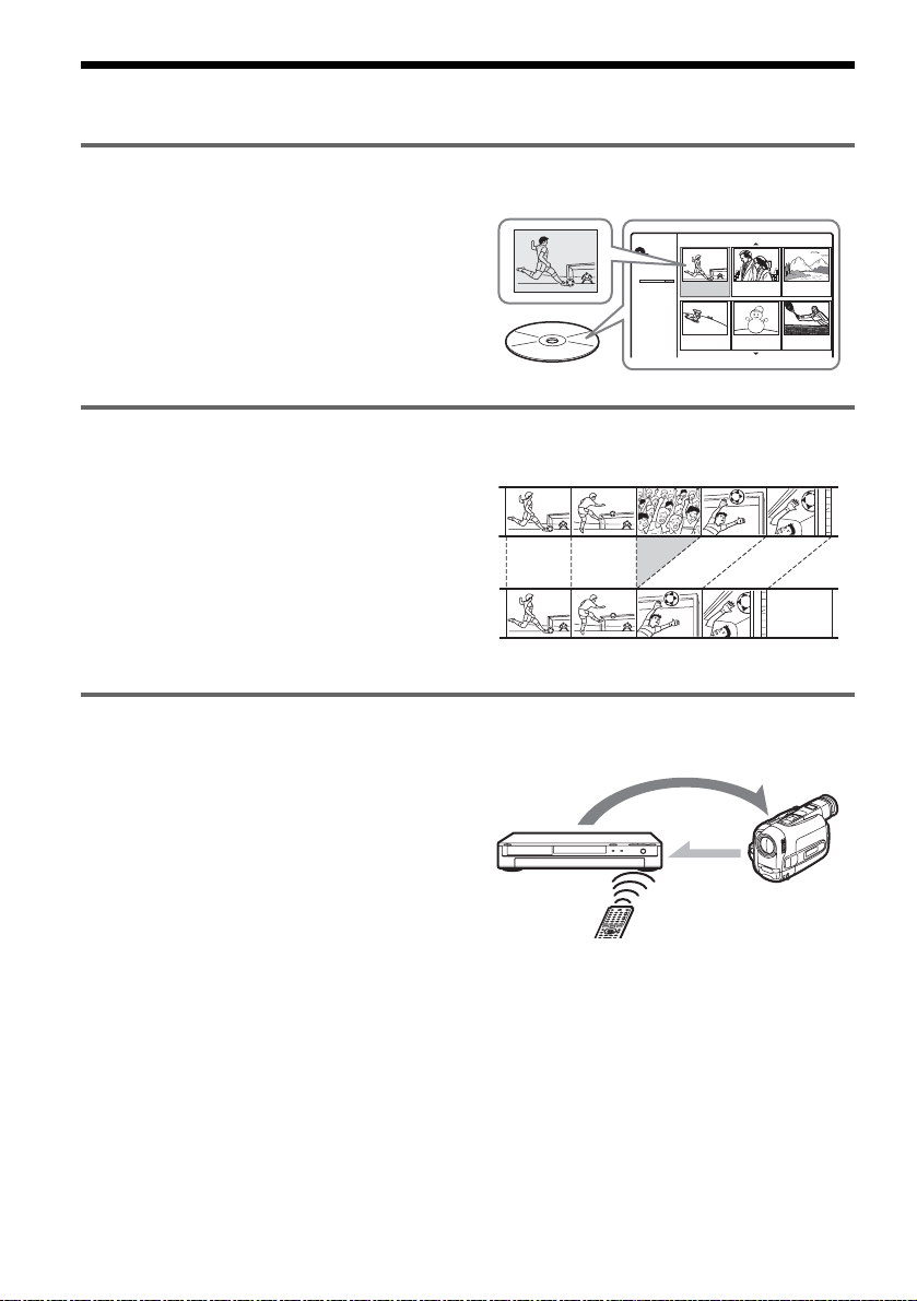
Ways to Use Your DVD Recorder/Home Theatre System
Quick access to recorded titles – Title List
, Display the Title List to see all of the titles
on the disc, including recording date, title
length, and thumbnail image (page 33).
Creating your own programme – Playlist
, Record a programme on a DVD-RW (VR
mode), then delete, move and add scenes at
will to create your own, original
programme (page 63).
Dubbing of DV/Digital8 tapes – DV Dubbing
, Connect your digital video camera to the
DV IN jack and dub the entire contents or
just selected scenes to a DVD disc
(page 70).
Title List
Title List
Original
DVD-RW
SLP
2:45:00
Free
Original
Playlist
Control
Title 1
07/12 0:45:00
Title 4
13/12 0:10:00
Title 2
09/12 1:00:00
Title 5
16/12 0:10:00
Title 3
10/12 0:15:00
Title 6
19/12 0:25:00
1/7
Dubbing
GB
6
Page 7

Progressive PAL playback
, If your TV is compatible with progressive
signals, you can enjoy accurate colour
reproduction and high quality images in
Progressive mode.
Playing JPEG image files
, You can enjoy viewing JPEG images on
your TV screen. First, take pictures with a
digital camera and save them in JPEG
format to a CD-R/CD-RW on a PC. Then
play the CD-R/CD-RW on this recorder
(page 61).
Shoot
Save
Play!
Listening multi channel sound with the speakers
, You can enjoy any commercially available
DVD VIDEO with the dynamic sound from
the 5.1ch speakers. The system has Sound
Field settings that simulate various acoustic
characteristics, allowing you to listen to TV
sound with the surround speakers, or full
5.1ch speakers (page 85).
A list of recordable and playable discs is on page 8.
GB
7
Page 8

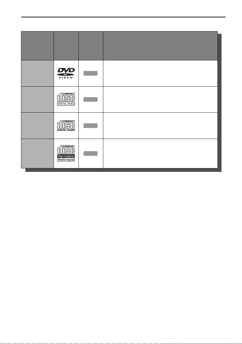
Quick Guide to Disc Types
Recordable and playable discs
Icon
Type
Disc
Logo
used in
this
Formatting
(new discs)
manual
DVD+RW
VR
mode
+
-
RWVR
Automatically
RW
formatted
Automatically
formatted in VR mode
DVDRW
DVD+R
DVD-R
Video
mode
-
RW
Manually reformat in
Video
Video mode (page 31)
Automatically
+
R
formatted
Automatically
-
R
formatted
Usable disc versions (as of February 2005)
• 4x-speed or slower DVD+RWs
• 4x-speed or slower DVD-RWs (Ver.1.1, Ver.1.2
with CPRM*
1
)
• 8x-speed or slower DVD+Rs
• 8x-speed or slower DVD-Rs (Ver.2.0)
Compatibility with
other DVD players
(finalizing)
Playable on DVD+RW
compatible players
(automatically finalized)
Playable only on VR mode
compatible players
(finalization unnecessary)
Playable on most DVD players
(finalization necessary)
(page 39)
Playable on most DVD+R
compatible players (finalization
necessary) (page 39)
Playable on most DVD players
(finalization necessary)
(page 39)
“DVD+RW,” “DVD-RW,” “DVD+R,” and “DVD-R,”
are trademarks.
*1
CPRM (Content Protection for Recordable Media) is
a coding technology that protects copyrights for
images.
*2
To free up disc space, erase the last title on the disc.
*3
Erasing titles does not free up disc space.
GB
8
Page 9

Recording Features Editing Features
Erase
Rewrite
(page 41)
Record
16:9 sizes
(page 83)
Auto
chapter
(page 83)
Erase title
(page 65)
A-B Erase
(page 65)
Manual
chapter
(page 68)
chapter/
Hide
chapter
(page 67)
Yes No Yes Yes *
2
No Yes No/Yes No
Yes Yes Yes Yes Yes Yes Yes/No Yes
Yes No Yes Yes *
No No Yes Yes *
No No Yes Yes *
2
No No No/No No
3
No Yes No/Yes No
3
No No No/No No
Discs that cannot be recorded on
• DVD-RWs (Ver.1.0)
• DVD+RWs that are not 2.4x-speed compatible
• Double layer discs
• 8 cm discs
Playlist
(page 63)
,continued
GB
9
Page 10
Playable discs
Type
DVD VIDEO Discs such as movies that can be purchased or rented
VIDEO CD
CD
DATA CD
Disc
Logo
Notes about CDs
• The recorder can play CD-ROMs/CD-Rs/CDRWs recorded in the following formats:
– music CD format
– video CD format
– MP3 audio tracks and JPEG image files of format
conforming to ISO9660* Level 1/Level 2, or its
extended format, Joliet
* A logical format of files and folders on CD-ROMs,
defined by ISO (International Organization for
Standardization).
• When playing DTS surround sound on a CD,
you can hear the sound from this speaker system
only. The audio signals are not output from the
LINE output jacks on the recorder.
Icon
used in
this
manual
DVD
VCD
CD
DATA CD
Characteristics
VIDEO CDs or CD-Rs/CD-RWs in VIDEO CD/Super
VIDEO CD format
Music CDs or CD-Rs/CD-RWs in music CD format that can
be purchased
CD-ROMs/CD-Rs/CD-RWs containing MP3 audio tracks
and JPEG image files
Discs that cannot be played
• All CD-ROMs (including PHOTO CDs)
• CD-Rs/CD-RWs, other than those recorded in
the format, listed above
• Data part of CD-Extras
• DVD-ROMs
• DVD Audio discs
• DVD-RAMs
• DVD+R DL (double layer) discs
• HD layer on Super Audio CDs
• DVD VIDEOs with a different region code
(page 11)
z Hint
This recorder can play 8 cm CDs and finalized 8 cm
DVDs.
10
GB
Page 11

Note on playback operations of DVD VIDEOs/
VIDEO CDs
Some playback operations of DVD VIDEOs/
VIDEO CDs may be intentionally set by software
producers. Since this recorder plays DVD
VIDEOs/VIDEO CDs according to the disc
contents the software producers designed, some
playback features may not be available. Also, see
the instructions supplied with the DVD VIDEOs/
VIDEO CDs.
Region code (DVD VIDEO only)
Your recorder has a region co de printed on the rear
of the unit and will only play DVD VIDEOs
(playback only) labelled with identical region
codes. This system is used to protect copyrights.
DVD VIDEOs labelled will also play on this
ALL
recorder.
If you try to play any other DVD VIDEO, the
message [Playback prohibited by region code]
will appear on the TV screen. Depending on the
DVD VIDEO, no region code indication may be
labelled even though playing the DVD VIDEO is
prohibited by area restrictions.
RDR–XXXX
X
XXV XXHz XXW
Region code
Notes
• Some DVD+RWs/DVD+Rs, DVD-RWs/DVD-Rs, or
CD-RWs/CD-Rs cannot be played on this recorder due
to the recording quality or physical condition of the
disc, or the characteristics of the recording device and
authoring software. The disc will not play if it has not
been correctly finalized. For more information, see the
operating instructions for the recording device.
• You cannot mix VR mode and Video mode on the same
DVD-RW. To change the disc’s format, reformat the
disc (page 31). Note that the disc’s contents will be
erased after reformatting.
• You cannot shorten the time required for recording
even with high-speed discs.
• It is recommended that you use discs with “For Video”
printed on their packaging.
• You cannot add new recordings to DVD-RWs (Video
mode) or DVD-Rs that contain recordings made on
other DVD equipment.
• In some cases, you may not be able to add new
recordings to DVD+RWs that contain recordings made
on other DVD equipment. If you do add a new
recording, note that this recorder will rewrite the DVD
menu.
• If the disc contains PC data unrecognizable by this
recorder, the data may be erased.
Music discs encoded with copyright protection
technologies
This product is designed to play back discs that
conform to the Compact Disc (CD) standard.
Recently, various music discs encoded with
copyright protection technologies are being
marketed by some record companies. Please be
aware that among those discs, there are some that
do not conform to the CD standard and may not be
playable by this product.
Note on DualDisc
A DualDisc is a two sided disc product which
mates DVD recorded material on one side with
digital audio material on the other side.
However, since the audio material side does not
conform to the Compact Disc (CD) standard,
playback on this product is not guaranteed.
11
GB
Page 12
Hookups and Settings
Step 1: Unpacking
Overview
Complete the following steps to start using this
DVD recorder/home theatre system.
Step 1: Unpacking (page 12)
m
Step 2: Connecting the Speaker System (page 14)
m
Step 3: Connecting the FM/AM Aerials (page 17)
m
Step 4: Connecting the Speaker System and
Recorder (page 18)
m
Step 5: Connecting the TV Aerial (page 19)
m
Step 6: Connecting the TV and Recorder (page 20)
m
Step 7: Connecting the Mains Leads (page 23)
m
Step 8: Initial Setup (page 28)
Steps 1 to 4 are for the speaker system; steps 5 and
6 for the recorder. After finishing all of the
hookups, connect the mains leads in step 7, and
start setting up the system in “Step 8: Initial
Setup.”
Notes
• Plug cords securely to prevent unwanted noise.
• See the instructions supplied wi th the components to be
connected.
• You cannot connect this recorder to a TV that does not
have a SCART or video input jack.
• Be sure to disconnect the mains lead of each
component before connecting.
Check that you have the following items.
In DVD carton box:
• DVD recorder (1)
• TV aerial cable (1)
In main carton box:
• Active subwoofer (1)
• Centre unit (1)
• Speakers (4)
•AM loop aerial (1)
• FM wire aerial (1)
• Speaker cords (short × 2, long × 2)
• Optical digital cord (1)
• Remote commander (remote) (1)
• R6 (size AA) batteries (2)
• Foot pads*
• Operating Instructions (1)
• Hookup Guide (card) (1)
* Attach the pads to the bottom of the speakers.
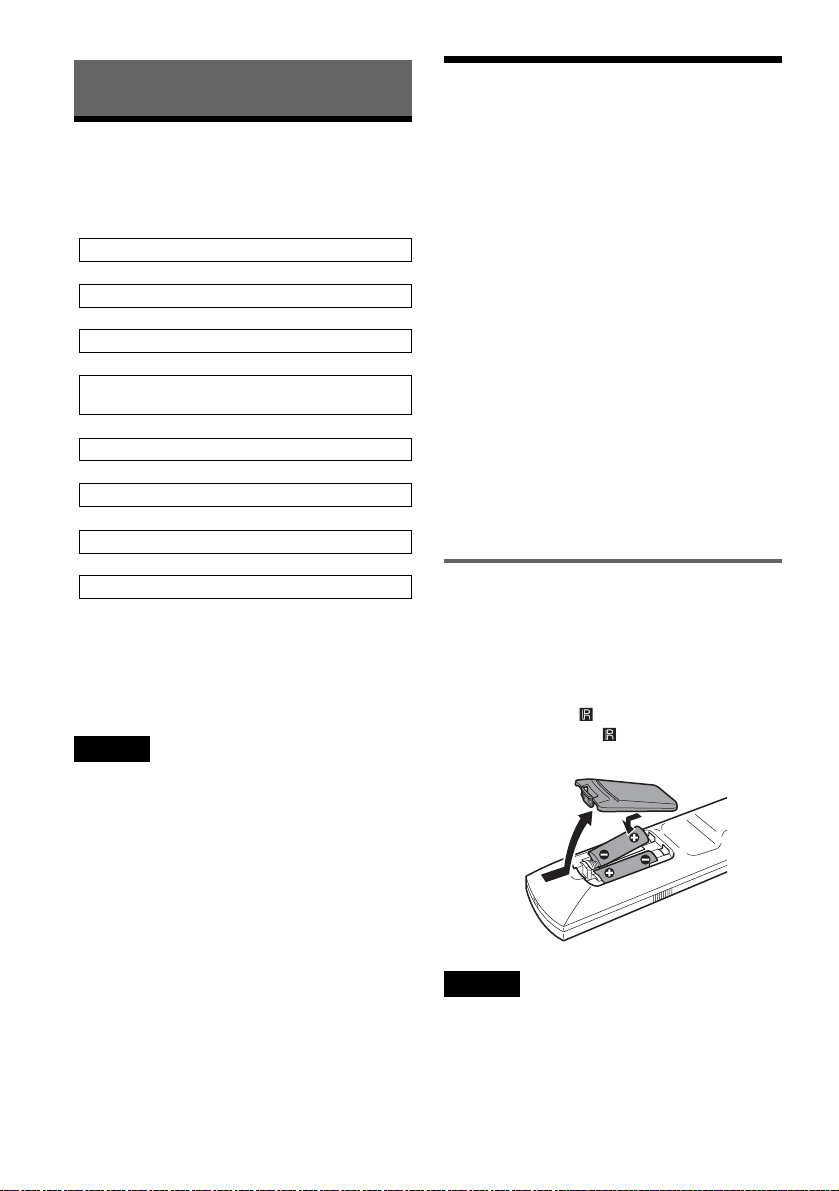
Inserting batteries into the remote
You can control the recorder and the speaker
system using the supplied remote. Insert two R6
(size AA) batteries by matching the 3 and # ends
on the batteries to the markings inside the
compartment.
Point the remote at (remote sensor) on the
recorder. Or, point it at on the centre unit when
operating the speaker system.
12
Notes
• If the supplied remote interferes your other Sony DVD
recorder or player, change the command mode number
for this recorder (page 99).
• If you are using a non Sony TV, set the code number
for the TV’s manufacturer (page 98).
• Use the batteries correctly to avoid possible leakage
and corrosion. Do not touch the liquid with bare hands
should leakage occur. Observe the following:
GB
Page 13

– Do not use a new battery with an old battery, or
batteries of different manufacturers.
– Do not attempt to recharge the batteries.
– If you do not intend to use the remote for an extended
period of time, remove the batteries.
– If battery leakage occurs, wipe out any liquid inside
the battery compartment, and insert new batteries.
• Do not expose the remote sensors (marked on the
recorder and the centre unit) to strong light, such as
direct sunlight or lighting apparatus. The system may
not respond to the remote.
Hookups and Settings
13
GB
Page 14

Step 2: Connecting the Speaker System
Connect the system components using the supplied cords as marked A and B below.
Front speaker (R)
Surround speaker (R)
Colour label
Subwoofer
Centre unit
FM
75 COAXIAL
SPEAKERS
FRONT R FRONT L SURR R SURR L CENTER
AERIAL
SYSTEM CONTROL
DIGITAL IN OPTICAL
Front speaker (L)
to SYSTEM
CONTROL
AM
DVD
B
System cord
Speaker cord
Surround speaker (L)
A
Notes
• Do not set the speakers in an inclined position.
• Do not place the speakers in locations that are:
– Extremely hot or cold
– Dusty or dirty
– Very humid
– Subject to vibrations
– Subject to direct sunlight
• Do not connect any speakers other than those supplied
with this system.
• Use caution when placing the speakers and/or speaker
stands (not supplied) that are attached with the speakers
on a specially treated (waxed, oiled, polished, etc.)
floor, as staining or discoloration may result.
GB
14
to SPEAKER jacks on the bottom side
Page 15
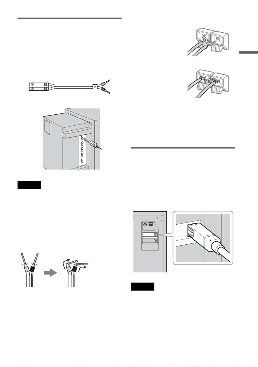
A Wiring the speakers
Connect the supplied speakers to the SPEAKER
jacks on the bottom side of the subwoofer using
the speaker cords.
Use the speaker cord whose tube is the same
colour as the jack label on the connecting speaker.
Example:
Too much insulation is
removed. Stripped cords are
touching each other.
Hookups and Settings
Grey
(+)
(–)
Colour tube
(+)
(–)
Black
Notes
• Cover the floor with a cloth when connecting.
• Be sure to match the polarity of the speaker cord and
the terminal on the component; 3 to 3 (grey), # to #
(black). If reversed, the sound will lack bass and may
be distorted.
Notes on speaker cord treatment
• Do not insert the speaker cord insulation in the
speaker terminals. Bend the stripped cord at the
end of the insulation before connecting.
Stripped cords are touching
the other speaker terminals.
After connecting the system components and the
mains leads, you can check for a speaker shortcircuit using the test tone (page 94). If the test tone
is not output, or is output from a speaker other than
indicated in the centre unit display, check the
speaker connection.
B Connecting the subwoofer and
the centre unit
Connect the system cord of the centre unit to the
SYSTEM CONTROL jack of the subwoofer,
then, connect the speaker cord to the CENTER
SPEAKER jack. Insert the plugs fully until they
click.
to SYSTEM CONTROL
AM
FM
75 COAXIAL
AERIAL
SYSTEM CONTROL
DIGITAL IN OPTICAL
DVD
NT
ROL
• To prevent short-circuiting of the speakers,
make sure the stripped speaker cord does not
touch the other stripped speaker cord or the
terminal.
Note
If the system cord is disconnected while the power is on,
the speaker system enters standby mode (page 101).
,continued
15
GB
Page 16
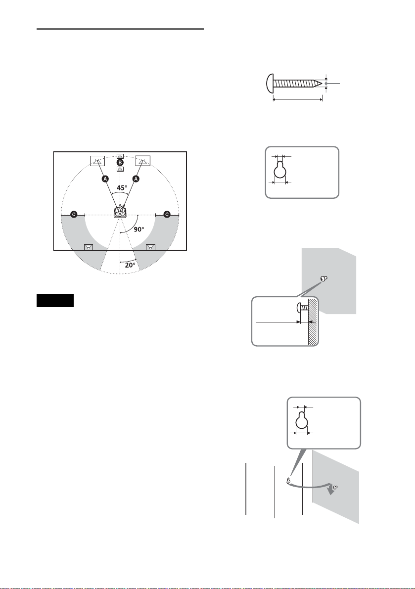
Positioning the speakers
For the best possible surround sound, all the
speakers other than the subwoofer should be the
same distance from the listening position (A).
However, this system allows you to place the
centre unit up to 1.6 m closer (B) and the
surround speakers up to 4.6 m closer (C) to the
listening position.
The front speakers can be placed from 1.0 to 7.0 m
(A) from the listening position.
Note
Do not place the centre unit and surround speakers
farther away from the listening position than the front
speakers.
To install the speakers on a wall
1 Prepare screws (not supplied) that are suitable
for the hole on the back of each speaker.
4mm
30mm
Hole on the back of the speaker
4.6mm
10mm
2 Fasten the screws to the wall.
The screws should protrude 5 to 7 mm.
5 to 7 mm
Note on subwoofer placement
If the subwoofer is placed too close to a CRT TV
or projector, magnetic leakage may interfere with
the video signals and cause colour irregularity.
Should this happen, turn off the TV or the
projector, wait for 15 to 30 minutes, and then turn
it on again. If the problem persists, try the
following:
– Place the subwoofer at least 0.3 m away from the
TV or the projector.
– Remove any mag netic object near the subwoofer
(healthcare devices, toys, etc.). Magnetic latches
on TV stands may also cause the problem.
GB
16
3 Hang the speakers on the screws.
Hole on the back of the speaker
4.6 mm
10 mm
Page 17
Notes
• Use screws that are suitable for the wall material and
strength. As a plaster board wall is especially fragile,
attach the screws securely to a beam and fasten them to
the wall. Install the speakers on a vertical, flat wall
where reinforcement is applied.
• Contact a screw shop or installer regarding the wall
material or screws to be used.
• Sony is not responsible for accident or damage caused
by improper installation, insufficient wall strength or
improper screw installation, natural calamity, etc.
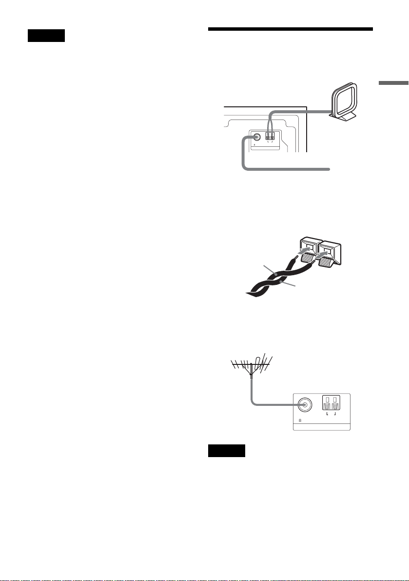
Step 3: Connecting the FM/
AM Aerials
Subwoofer
AM loop aerial
AM
FM
75 COAXIAL
AERIAL
FM wire aerial (supplied)
z Hints
• When connecting the AM loop aerial, cord (A) or cord
(B) can be connected to either terminal.
A
• If you have poor FM reception, use a 75-ohm coaxial
cable (not supplied) to connect the system to an
outdoor FM aerial as shown below.
Outdoor FM aerial
(not supplied)
(supplied)
B
Hookups and Settings
Subwoofer
FM
75 COAXIAL
AM
AERIAL
Notes
• To prevent noise pickup, keep the AM loop aerial away
from the system and other equipment.
• Be sure to fully extend the FM wire aerial.
• After connecting the FM wire aerial, keep it as
horizontal as possible.
17
GB
Page 18
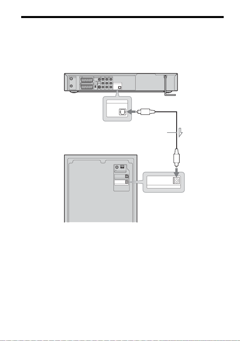
Step 4: Connecting the Speaker System and Recorder
Connect the DVD (DIGITAL IN OPTICAL) jack of the subwoofer to the DIGITAL OUT (OPTICAL)
jack of the recorder using the supplied optical digital cord.
DVD recorder
COMPONENT
LINE 2 OUT
AERIAL
IN
OUT
to DIGITAL
OUT (OPTICAL)
Subwoofer
LINE 3 / DECODER
LINE 1 - TV
DIGITAL OUT
COAXIAL
PCM/DTS/
MPEG/
DOLBY DIGITAL
VIDEO OUT
SELECT
RGB
COMPO-
NENT
LINE 2 OUT
S VIDEO
VIDEO OUT
L
PB/C
B
R
PR/C
R
Y
LINE 4 IN
L
AUDIO
AUDIO
R
PCM/DTS/MPEG/
DOLBY DIGITAL
VIDEO
VIDEO
DIGITAL OUT
PCM/DTS/MPEG/
DOLBY DIGITAL
OPTICAL
DIGITAL OUT
OPTICAL
FM
75 COAXIAL
DIGITAL IN OPTICAL
AM
AERIAL
SYSTEM CONTROL
DVD
Optical
digital cord
(supplied)
DIGITAL IN OPTICAL
DVD
18
to DVD (DIGITAL IN
OPTICAL)
GB
Page 19
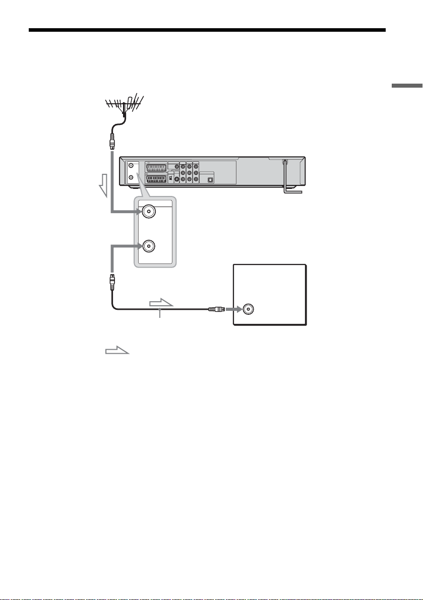
Step 5: Connecting the TV Aerial
Connect the TV aerial cable following the steps below. Do not connect the mains lead until you reach
“Step 7: Connecting the Mains Leads” (page 23).
Hookups and Settings
to AERIAL IN
AERIAL
LINE 3 / DECODER
IN
LINE 1 - TV
OUT
AERIAL
IN
DIGITAL OUT
COAXIAL
PCM/DTS/
MPEG/
DOLBY DIGITAL
VIDEO OUT
SELECT
RGB
COMPO-
NENT
COMPONENT
LINE 2 OUT
LINE 4 IN
VIDEO OUT
L
L
PB/C
B
AUDIO
AUDIO
LINE 2 OUT
DIGITAL OUT
R
R
PR/C
R
PCM/DTS/MPEG/
DOLBY DIGITAL
OPTICAL
Y
VIDEO
VIDEO
S VIDEO
DVD recorder
OUT
TV
to AERIAL OUT
TV aerial cable (supplied)
: Signal flow
1 Disconnect the TV aerial cable from your TV and connect it to AERIAL IN on the rear panel of
the recorder.
2 Connect AERIAL OUT of the recorder to the aerial input of your TV, using the supplied TV aerial
cable.
19
GB
Page 20
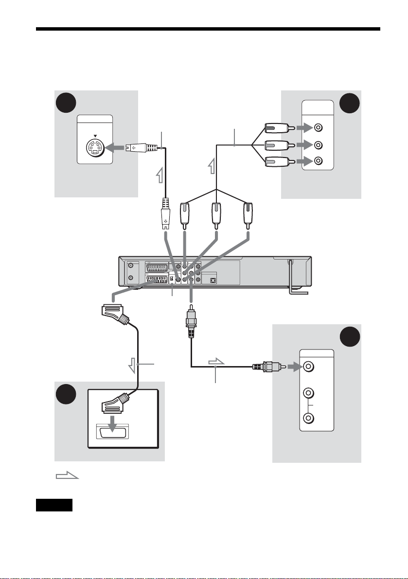
Step 6: Connecting the TV and Recorder
Connect the video cord to view pictures. Select one of following patterns A through D according to the
input jack on your TV monitor or projector.
C
INPUT
S VIDEO
TV, projector, or AV
amplifier (receiver)
to i
LINE1-TV
A
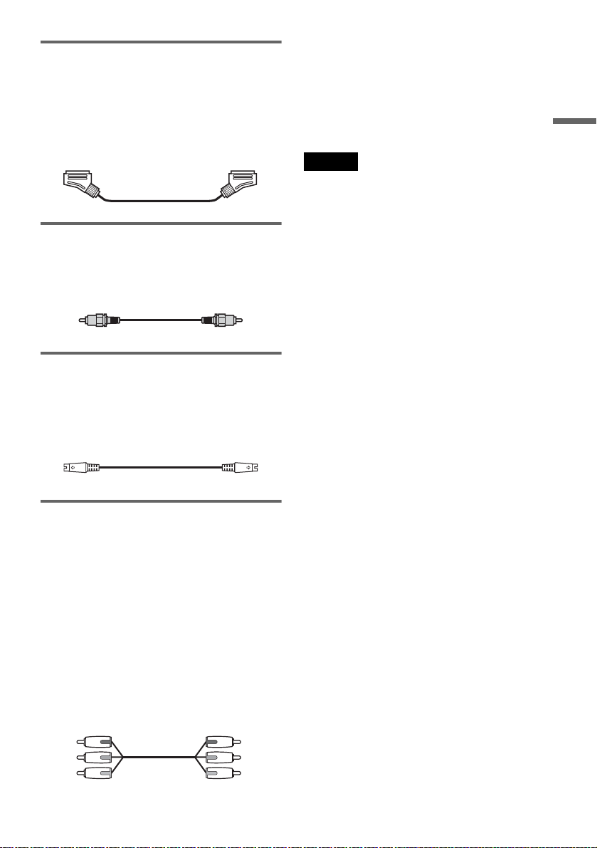
S-video cord
(not supplied)
to LINE 2 OUT
(S VIDEO)
AERIAL
LINE 3 / DECODER
IN
LINE 1 - TV
OUT
VIDEO OUT
SELECT switch
SCART
cord (not
supplied)
Component video
cord (not supplied)
COMPONENT
LINE 2 OUT
LINE 4 IN
DIGITAL OUT
VIDEO OUT
COAXIAL
PCM/DTS/
MPEG/
L
L
DOLBY DIGITAL
PB/C
B
AUDIO
AUDIO
VIDEO OUT
LINE 2 OUT
SELECT
RGB
COMPO-
NENT
DIGITAL OUT
R
R
PR/C
R
PCM/DTS/MPEG/
DOLBY DIGITAL
OPTICAL
Y
VIDEO
VIDEO
S VIDEO
to LINE 2 OUT (VIDEO)
Video cord
(not supplied)
(red)(blue)
TV, projector, or AV
amplifier (receiver)
(green)
to COMPONENT
VIDEO OUT
COMPONENT
VIDEO IN
Y
(green)
P
B
(blue)
P
R
(red)
DVD recorder
INPUT
VIDEO
L
AUDIO
R
D
B
TV
: Signal flow
Note
Do not connect more than one type of video cord between the recorder and your TV at the same time.
GB
20
TV, projector, or AV
amplifier (receiver)
Page 21
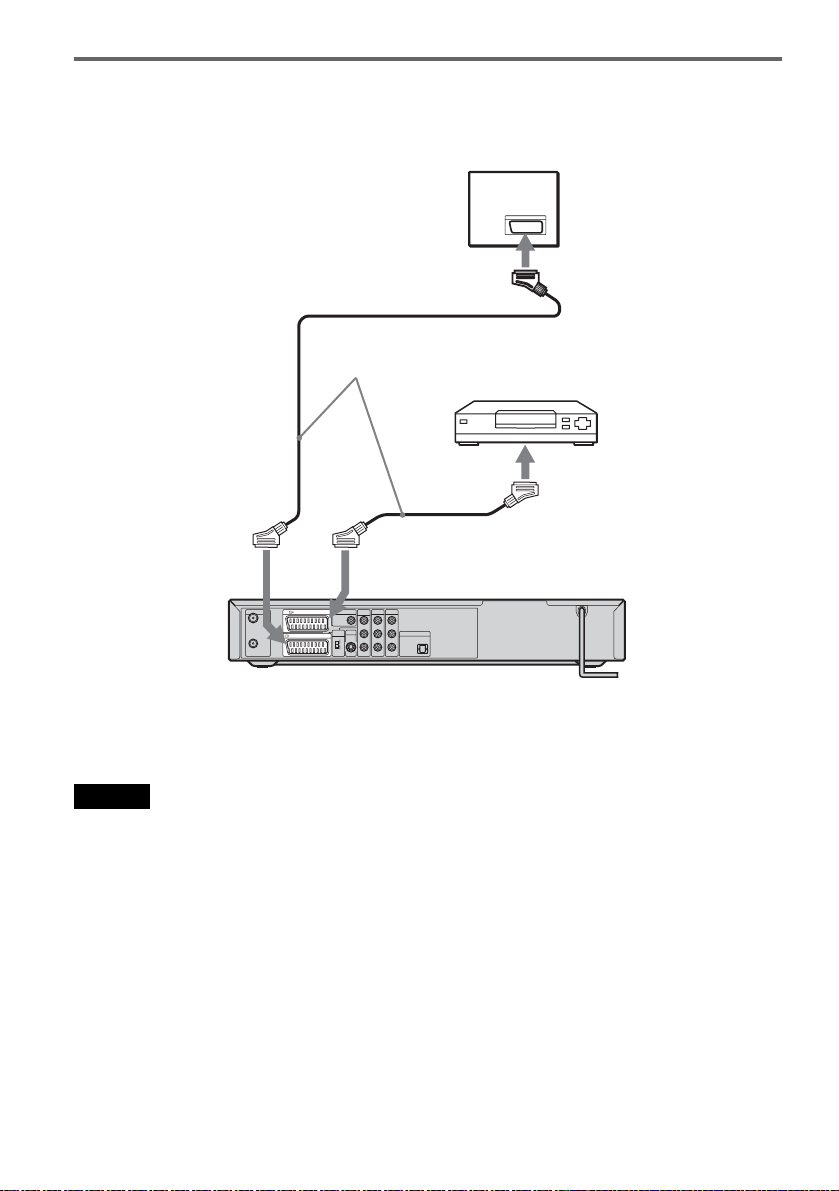
A Connecting to a SCART input jack
Connect using a SCART cord (not supplied) to the
LINE 1-TV jack and your TV. Be sure of a firm
connection to avoid hum and noise.
See the operating instructions supplied with the
TV to be connected. Set the VIDEO OUT
SELECT switch on the rear panel to “RGB.”
B Connecting to a video input jack
Connect using a video cord (not supplied) to the
yellow LINE 2 OUT (VIDEO) jack. You will
enjoy standard quality images.
C Connecting to an S VIDEO input
jack
Connect using an S-video cord (not supplied) to
the LINE 2 OUT (S VIDEO) jack. You will enjoy
high quality images.
When playing “wide screen” images
Some recorded images may not fit your TV
screen. To change the aspect ratio, see page 78.
If you are connecting to a VCR
Connect your VCR to the LINE 3/DECODER
jack on the recorder (page 24).
Notes
• Consumers should note that not all high definition
television sets are fully compatible with this product
and may cause artifacts to be displayed in the picture.
In the case of 625 progressive scan picture problems, it
is recommended that the user switch the connection to
the ‘standard definition’ output. If there are questions
regarding our TV set compatibility with this model
625p DVD recorder, please contact our customer
service centre.
• When you connect the recorder to your TV via the
SCART jacks, the TV’s input source is set to the
recorder automatically when you turn the recorder on.
If necessary, press TV/DVD on the remote to return the
input to TV.
Hookups and Settings
D Connecting to component video
input jacks (P
Connect the COMPONENT VIDEO OUT jacks
using a component video cord (not supplied) or
three video cords (not supplied) of the same kind
and length. You will enjoy accurate colour
reproduction and high quality images.
Set the VIDEO OUT SELECT switch on the rear
panel to “COMPONENT.”
If your TV accepts progressive 625p format
signals, you must use this connection and set
[Progressive Mode] in [Settings] Setup to [On]
(see page 78). The PROGRESSIVE indicator
lights up on the recorder.
Green
Blue
Red
B/CB, PR/CR, Y)
Green
Blue
Red
,continued
21
GB
Page 22

Connecting the audio cords
If you use your TV’s speakers for listening to sound, connect the LINE 2 OUT jacks of the recorder to
the audio input jacks of your TV.
INPUT
VIDEO
L
AUDIO
R
LINE 2 OUT
L
AUDI O
R
(white)
(red)
Audio cord
(not supplied)
(white)
(red)
VIDEO
to LINE 2 OUT (AUDIO L/R)
COMPONENT
LINE 2 OUT
AERIAL
LINE 3 / DECODER
IN
LINE 1 - TV
OUT
DIGITAL OUT
COAXIAL
PCM/DTS/
MPEG/
DOLBY DIGITAL
VIDEO OUT
SELECT
RGB
COMPO-
NENT
LINE 4 IN
VIDEO OUT
L
L
PB/C
B
AUDIO
AUDIO
LINE 2 OUT
DIGITAL OUT
R
R
PR/C
R
PCM/DTS/MPEG/
DOLBY DIGITAL
OPTICAL
Y
VIDEO
VIDEO
S VIDEO
: Signal flow
z Hint
You can connect an AV amplifier to the DIGITAL OUT
(COAXIAL) jack. Make the appropriate settings under
[Audio] setup (page 80). All the surround effects of the
system cannot be used.
Notes
• Do not connect your TV’s audio output jacks to the
LINE IN (AUDIO L/R) jacks at the same time. This
will cause unwanted noise to come from your TV’s
speakers.
• Do not connect the LINE 4 IN (AUDIO L/R) and LINE
2 OUT (AUDIO L/R) jacks to your TV’s audio output
jacks at the same time. This will cause unwanted noise
to come from your TV’s speakers.
TV, projector, or AV
amplifier (receiver)
To use the recorder’s surround function
With the audio connection above, you can enjoy
virtual surround sound effects created from the left
and right speakers.
Press SUR on the remote to turn on the function.
[SUR ON] appears on the TV screen
To turn off the function, press SUR again.
22
GB
Page 23

Step 7: Connecting the
Mains Leads
To turn the recorder on and off
Press DVD [/1.
When you tu rn off the recorder, the recorder enters
standby mode.
Plug the recorder, subwoofer, and TV mains leads
(power cords) into the mains.
DVD recorder
to mains
Subwoofer
to mains
Check that the "/1 indicator on the centre unit
lights up when the subwoofer mains lead is
connected.
Centre unit
FUNCTION VOLUMEVOLUME
To turn the speaker system on and off
Press AMP [/1.
When you turn off the speaker system, the speaker
system enters standby mode and the [/1 indicator
on the centre unit display lights up in red.
Hookups and Settings
"/1 indicator
After you connect the recorder mains lead, you
must wait a short while before operating the
recorder. You can operate the recorder once the
front panel display lights up and the recorder
enters standby mode.
If you connect additional equipment to this
recorder, go to “Connecting the Recorder to Other
Equipment” (page 24) before connecting the
mains leads.
After all connections are complete, follow the
steps of “Step 8: Initial Setup” (page 28).
23
GB
Page 24

Connecting the Recorder to Other Equipment
Connect other equipment (VCR, satellite tuner, PAY-TV decoder, etc.) to the LINE IN jacks of the
recorder.
Disconnect the recorder’s mains lead from the mains when connecting them.
Use the DV IN jack on the front panel if the equipment has a DV output jack (i.LINK jack) (page 71).
See also the operating instructions supplied with the connected equipment.
To record on this recorder, see “Recording From Connected Equipment” (page 49). To listen to the sound
of other equipment through the speaker system, see “Enjoying TV or VCR Sound From the Speaker
System” (page 90).
Connecting a VCR or similar device
To connect to the LINE 3 jack
Connect a VCR or similar recording device to the LINE 3/DECODER jack of this recorder.
TV
VCR
SCART cord
(not supplied)
to SCART input
to i
LINE1-TV
AERIAL
LINE 3 / DECODER
IN
LINE 1 - TV
OUT
to i LINE
3/DECODER
COMPONENT
LINE 2 OUT
DIGITAL OUT
VIDEO OUT
COAXIAL
PCM/DTS/
MPEG/
L
DOLBY DIGITAL
PB/C
B
VIDEO OUT
LINE 2 OUT
SELECT
RGB
R
PR/C
R
COMPO-
Y
NENT
S VIDEO
DVD recorder
LINE 4 IN
L
AUDIO
AUDIO
DIGITAL OUT
R
PCM/DTS/MPEG/
DOLBY DIGITAL
OPTICAL
VIDEO
VIDEO
Notes
• Pictures containing copy protection signals, which a prohibit copying, cannot be recorded.
• If you pass the recorder signals via the VCR, you may not receive a clear image on your TV screen.
VCRDVD recorder TV
Be sure to connect your VCR to the DVD recorder and your TV in the order shown below. To watch video tapes,
watch the tapes through a second line input on your TV (“Line input 2” below).
Line input 1
VCR DVD recorder TV
Line input 2
• When you record to a VCR from this DVD recorder, do not switch the input source to TV by pressing the TV/DVD
button on the remote.
• If you disconnect the recorder’s mains lead, you will not be able to view the signals from the connected VCR.
GB
24
Page 25
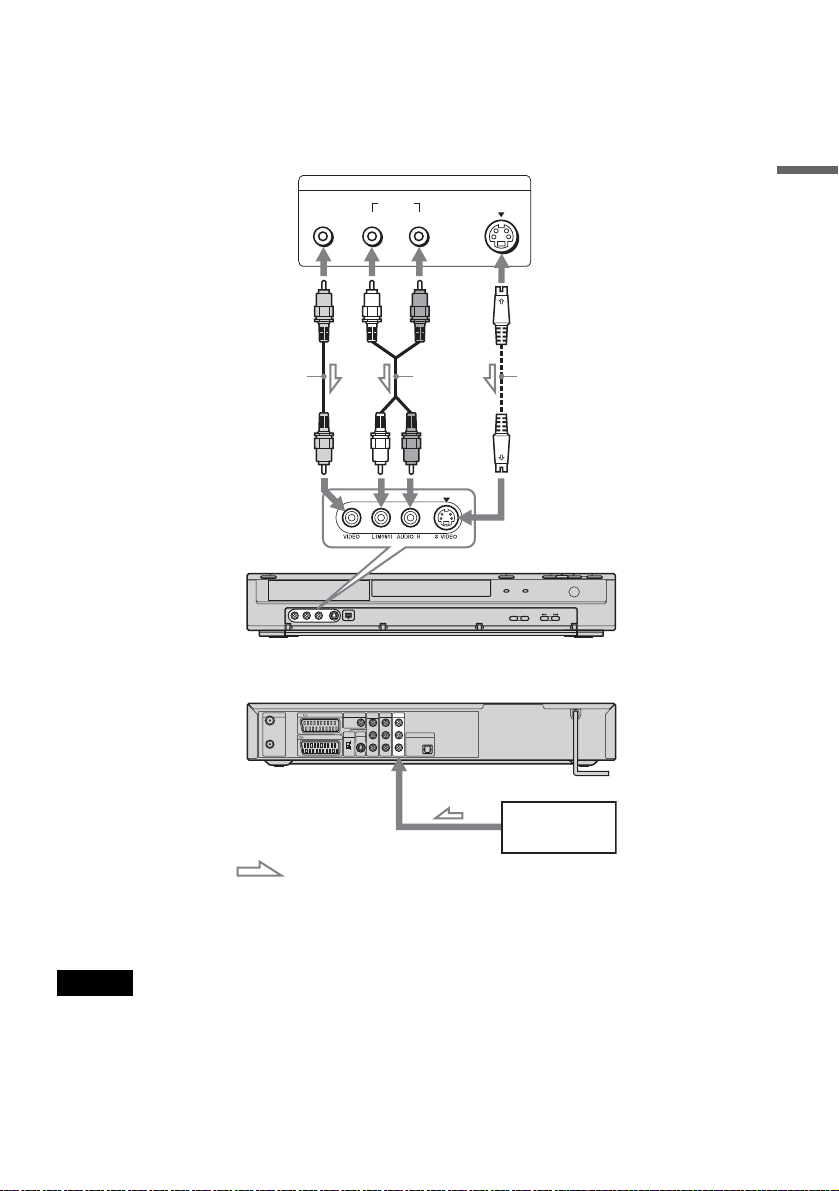
To connect to the LINE 2 IN or LINE 4 IN jacks
Connect a VCR or similar recording device to the LINE 2 IN or LINE 4 IN jacks of this recorder. If you
are connecting to the LINE 2 IN jacks and the equipment has an S-video jack, you can use an S-video
cord instead of a video cord.
VCR, etc.
OUTPUT
VIDEO
AUDIO
LR
S VIDEO
Hookups and Settings
Video cord
(not supplied)
Audio cord
(not
supplied)
S-video cord
(not supplied)
to LINE 2 IN DVD recorder (front)
(rear)
COMPONENT
LINE 2 OUT
AERIAL
LINE 3 / DECODER
IN
LINE 1 - TV
OUT
DIGITAL OUT
COAXIAL
PCM/DTS/
MPEG/
DOLBY DIGITAL
VIDEO OUT
SELECT
RGB
COMPO-
NENT
LINE 4 IN
VIDEO OUT
L
L
PB/C
B
AUDIO
AUDIO
LINE 2 OUT
DIGITAL OUT
R
R
PR/C
R
PCM/DTS/MPEG/
DOLBY DIGITAL
OPTICAL
Y
VIDEO
VIDEO
S VIDEO
to LINE 4 IN
VCR, etc.
: Signal flow
z Hint
When the connected equipment outputs only monaural sound, use audio cords that distribute monaural sounds to left/
right channels (not supplied).
Notes
• Do not connect the yellow LINE IN (VIDEO) jack when using an S-video cord.
• Do not connect the output jack of this recorder to another equipment’s input jack with the other equipment’s output
jack connected to the input jack of this recorder. Noise (feedback) may result.
• Do not connect more than one type of video cord between the recorder and your TV at the same time.
,continued
25
GB
Page 26
Connecting to a satellite or digital tuner
Connect a satellite or digital tuner to this recorder using the LINE 3/DECODER jack. Disconnect the
recorder’s mains lead from the mains when connecting the tuner.
TV
to SCART input
SCART cord (not
supplied)
Satellite tuner, etc.
to i
LINE1-TV
AERIAL
LINE 3 / DECODER
IN
LINE 1 - TV
OUT
to i LINE
3/DECODER
COMPONENT
LINE 2 OUT
DIGITAL OUT
VIDEO OUT
COAXIAL
PCM/DTS/
MPEG/
L
DOLBY DIGITAL
PB/C
B
AUDIO
VIDEO OUT
LINE 2 OUT
SELECT
RGB
R
PR/C
R
COMPO-
Y
NENT
VIDEO
S VIDEO
LINE 4 IN
L
AUDIO
R
VIDEO
z Hint
You do not need to turn on the recorder to view the
signals from the connected tuner on your TV.
Notes
• If you are using a B Sky B tuner, be sure to connect the
tuner’s VCR SCART jack to the LINE 3/DECODER
jack.
• If you disconnect the recorder’s mains lead, you will
not be able to view the signals from the connected
tuner.
• When the recorder is turned off, the LINE 3/
DECODER jack does not accept 16:9 screen size
signals.
DIGITAL OUT
PCM/DTS/MPEG/
DOLBY DIGITAL
OPTICAL
DVD recorder
26
GB
Page 27

Connecting a PAY-TV/Canal Plus decoder
You can watch or record PAY-TV/Canal Plus programmes if you connect a decoder (not supplied) to the
recorder. Disconnect the recorder’s mains lead from the mains when connecting the decoder.
To watch or record PAY-TV/Canal Plus programmes, set your recorder to receive the channels using the
Setup Display. See “[Channel Settings]” in [Settings] Setup (page 75).
Aerial cabl e
(supplied)
to AERIAL IN
to SCART input
TV
Hookups and Settings
SCART cord (not
supplied)
AERIAL
IN
OUT
to i
LINE1TV
LINE 3 / DECODER
LINE 1 - TV
to i LINE
3/DECODER
COMPONENT
LINE 2 OUT
DIGITAL OUT
VIDEO OUT
COAXIAL
PCM/DTS/
MPEG/
L
DOLBY DIGITAL
PB/C
B
AUDIO
VIDEO OUT
LINE 2 OUT
SELECT
RGB
R
PR/C
R
COMPO-
Y
NENT
VIDEO
S VIDEO
to AERIAL
OUT
z Hint
You do not need to turn on the recorder to view the
signals from the connected tuner on your TV.
Notes
• To watch or record PAY-TV/Canal Plus programmes
from the LINE 1-TV jack, set [Line1 Decoder] in
[Settings] Setup to [On] (page 78).
• If you disconnect the recorder’s mains lead, you will
not be able to view the signals from the connected
decoder.
SCART cord (not
supplied)
LINE 4 IN
L
AUDIO
DIGITAL OUT
R
PCM/DTS/MPEG/
DOLBY DIGITAL
OPTICAL
VIDEO
PAY-TV/Canal
Plus decoder
DVD recorder
27
GB
Page 28

Step 8: Initial Setup
Use the Setup Displays and AMP menu to make
the initial settings for using the system. Complete
the initial setup in the following order.
1. Tuner and channel setup
m
2. OSD language setup
m
3. Clock setup
m
4. TV type setup
m
5. Basic speaker setup
4 While the recorder is in stop mode, set the
AMP/DVD switch to DVD, and press SET
UP.
The Setup Display appears, which allows you
to make adjustments to the recorder. For
details about the Setup Display, see page 74.
Example:
Settings
Auto Preset
Channel Settings
Clock
TV Aspect
Display Mode
Line1 Decoder
Progressive Mode
PBC
Factory Setup
France
Start
Follow the steps from “1. Tuner and channel
setup” to “5. Basic speaker setup” below.
AMP/DVD
switch
DVD
AMP MENU
</M/m/,,
ENTER
SET UP
1 2 3
4 6
5
7 8 9
0
DVD "/1
AMP "/1
1. Tuner and channel setup
1 Turn on the TV.
2 Press DVD [/1 to turn on the recorder.
3 Switch the input selector on your TV so that
the signal from the recorder appears on
your TV screen.
For UK models, go to step 6.
5 Press M/m to select your country, and
press ,.
If your country is not listed, select [Other].
Note that if you select [Other], you cannot
select [Auto Adjust On] in [Clock] Setup
(page 77).
6 Press ENTER while [Start] is selected.
The recorder automatically starts searching
for all the receivable channels and presets
them.
Settings
Auto Preset
Channel Settings
Clock
TV Aspect
Display Mode
Line1 Decoder
Progressive Mode
PBC
Factory Setup
Sweden
Stop
Searching 11%
To manually set, disable, or fine-tune the
channels, see “[Channel Settings]” in
[Settings] Setup (page 75). For customers in
France, set each channel to [SECAM] in the
[Channel Settings] menu if the reception is
poor (page 75).
7 Press < to return to the Setup Display,
and follow the steps of “2. OSD language
setup” (see below).
If you do not want to change the on-screen
display language, go to “3. Clock setup”
(page 29).
28
GB
Page 29
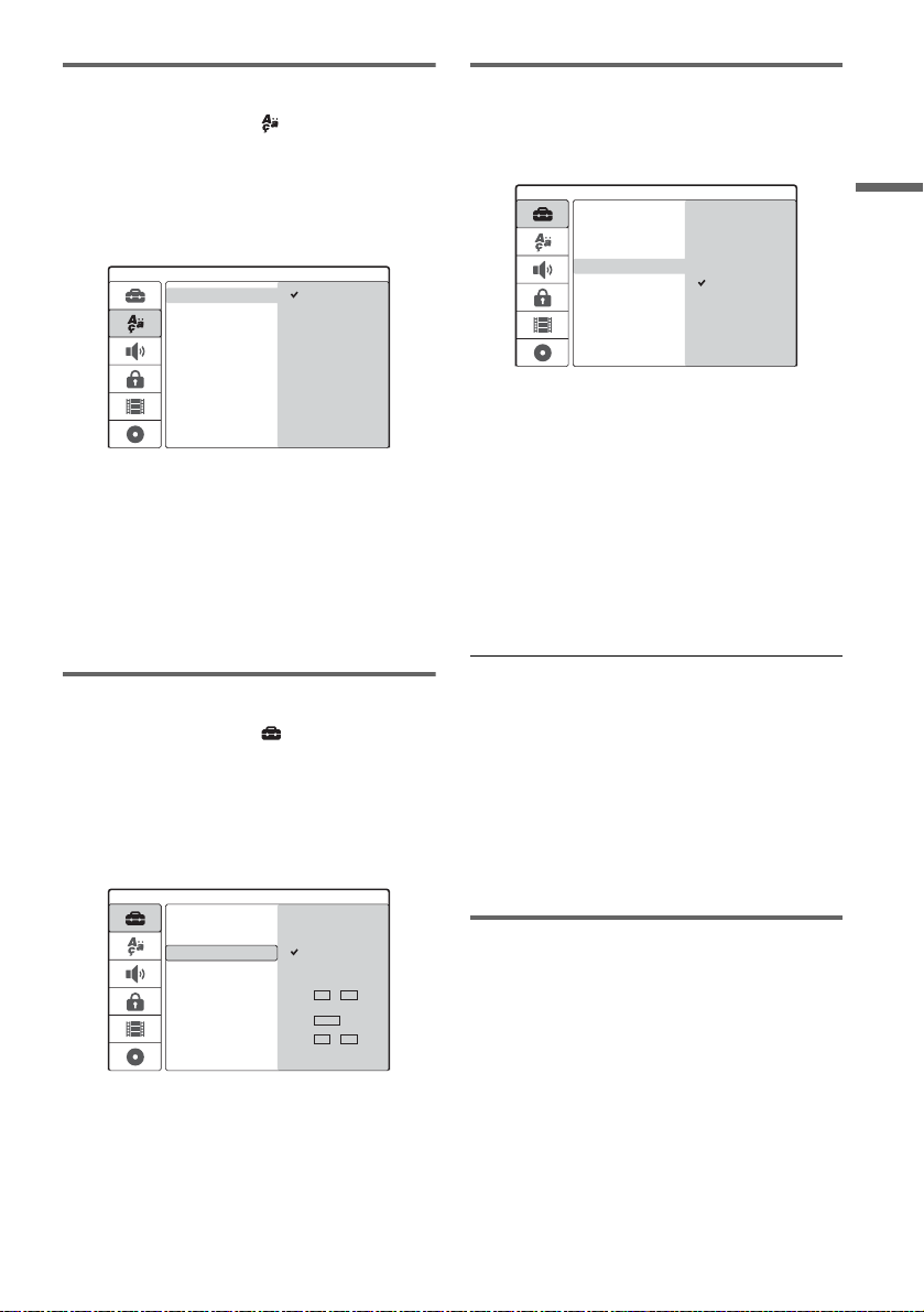
2. OSD language setup
1 Press M/m to select [Language]
(language), and press ,.
[Language] Setup appears.
2 Press M/m to select [OSD] (on-screen
display), and press ,.
Language
OSD
Menu
Audio
Subtitle
English
Deutsch
Italiano
Español
Português
3 Press M/m to select a language, and press
ENTER.
The on-screen language changes to the
selected language.
4 Press < to return to the Setup Display,
and follow the steps of “3. Clock setup”
(see below).
4. TV type setup
1 Press M/m to select [TV Aspect], and press
,.
Settings
Auto Preset
Channel Settings
Clock
TV Aspect
Display Mode
Line1 Decoder
Progressive Mode
PBC
Factory Setup
4:3
16:9
2 Press M/m to select the aspect ratio of the
connected TV, and press ENTER.
[4:3]: For a standard 4:3 screen TV without a
wide screen mode. Select [Display Mode] in
[Settings] Setup.
[16:9]: For a wide-screen TV or standard TV
with a wide screen mode.
3 Press SET UP to turn off the Setup Display,
and follow the steps of “5. Basic speaker
setup” (page 29).
Hookups and Settings
3. Clock setup
1 Press M/m to select [Settings], and
press ,.
[Settings] Setup appears.
2 Press M/m to select [Clock], and check
that the clock is correctly set.
Settings
Auto Preset
Channel Settings
Clock
TV Aspect
Display Mode
Line1 Decoder
Progressive Mode
PBC
Factory Setup
Auto Adjust On
Auto Adjust Off
Date 12 / 04
Year 2005
Time 12 : 00
If incorrect, set the clock manually (page 77).
Or, the timer recording does not work
properly.
3 Follow the steps of “4. TV type setup” (see
below).
If you connect a TV that accepts progressive
625p format signals to the COMPONENT VIDEO
OUT jacks
Set [Progressive Mode] in [Settings] Setup to [On]
(page 78).
z Hint
You can make other adjustments using the Setup
Displays, such as picture, sound, and subtitle languages.
(See “DVD Recorder Set-Up Menu” on page 74.)
5. Basic speaker setup
You can reflect the current speaker positions on
the system. Enter the speaker distance from your
listening position using the AMP menu on the
centre unit display. For details about the AMP
menu, see page 91; about speaker placement, see
page 16.
1 Press AMP [/1 to turn on the speaker
system.
If “FM” or “AM” appears on the centre unit
display, press DVD on the remote to display
“DVD.”
,continued
29
GB
Page 30

2 Set the AMP/DVD switch to AMP, point the
remote at the centre unit, and press AMP
MENU.
The AMP menu appears.
3 Press M/m to select “SP SETUP” (speaker
setup), and press ENTER or ,.
Example:
4 Press M/m to select “SURR SP” (surround
speaker), and press ENTER or ,.
SL SR
5 Press M/m to select the setting for the
position.
If unsure about the position, see ““SURR SP”
(surround speaker)” on page 92.
6 Press < to return to the previous layer.
7 Press M/m to select “FRONT DIST” (front
speaker distance), and press ENTER or
,.
11Press AMP MENU to turn off the AMP
menu.
To better adjust the speaker system
You can change the speaker level etc. See
“Speaker Level Settings (“LEVEL”)” (page 93).
Basic hookups and settings are complete.
You are ready to start using the system.
L R
8 Press M/m to set the front speaker
distance from the listening position.
The display changes in 0.2 m increments,
from 1.0 to 7.0 m. Enter the shorter distance if
the two speaker distances differ.
Example: When entering 5.8 m for the front
left and right speakers.
L R
9 Press < to return to the previous layer.
10Repeat steps 7 to 9 to set “CEN DIST”
(centre speaker distance) and “SURR
DIST” (surround speaker distance).
GB
30
m
m
Page 31

DVD Recorder Basics
Inserting and Formatting a
Disc
+
-
RWVR-RW
RW
When you first insert a new disc, the recorder will
ask you to format the disc. Follow the steps below
to format the disc. You can also reformat a
DVD+RW or DVD-RW to create a blank disc.
Z
Video
1 2 3
4 6
5
7 8 9
0
+
R
-
R
AMP/DVD switch
DVD "/1
Labelled side facing up
6 Press Z (open/close) to close the disc
tray.
After “LOADING” disappears from the front
panel display, the display asks for
confirmation.
7 Press < to select [OK] and press ENTER.
The recorder starts formatting the disc.
The display shows the approximate time
required.
8 Press ENTER when [OK] appears.
• For a DVD-RW, the recorder automatically
formats in VR mode. To format in Video
mode, see “Reformatting a disc” below.
DVD Recorder Basics
</M/m/,,
ENTER
SET UP
1 Turn on the TV.
2 Press DVD &/1.
The recorder turns on.
3 Switch the input selector on your TV so that
the signal from the recorder appears on the
TV screen.
4 Set the AMP/DVD switch to DVD.
5 Press Z (open/close), and place a disc on
the disc tray.
z Hint
For a formatted disc, you can use the disc after
“LOADING” disappears from the front panel display in
step 6 above.
Reformatting a disc
+
-
RWVR-RW
RW
You can erase all contents of a disc to create a
blank disc. To format a new DVD-RW in Video
mode, reformat the disc.
Video
1 Insert a disc.
2 Set the AMP/DVD switch to DVD, and press
SET UP to turn on the Setup Display.
3 Select [Disc Info] and press ,.
4 Select [Format DVD] and press ,.
Disc Info
Format DVD
Finalize
Disc Name
Protect
Start
,continued
31
GB
Page 32

5 While [Start] is selected, press ENTER.
The display asks for confirmation.
• For DVD-RWs, select a recording format
(VR mode or Video mode) and press
ENTER.
6 Select [OK] and press ENTER.
Formatting starts.
Recording a TV Programme
on a Disc
+
RW
This section introduces the basic operation to
record the current TV programme on a disc.
For details about recording, see page 41.
-
RWVR
-
RW
Video
-
+
R
R
z REC
REC MODE
1 2 3
4 6
5
7 8 9
0
PROG +/–
x
1 Insert a disc.
For details on how to insert and format a new
disc, see “Inserting and Formatting a Disc”
(page 31).
2 Press PROG +/– to select the programme
position you want to record.
3 Press REC MODE repeatedly to select the
recording mode.
Each time you press the button, the display
changes on the TV screen as follows:
HQ SP EP SLP
32
For details about the recording mode, see
page 41.
4 Press z REC.
Recording starts and “z” (red) appears in the
front panel display.
Recording continues until you stop the
recording or the disc is full.
GB
Page 33

To stop recording
Press x. Note that it may take a few seconds for
recording to stop.
z Hint
This recorder can record on various discs. Select the disc
type according to your needs (page 8).
Viewing Recorded TV
Programmes (Title List)
+
-
RW
RWVR-RW
Video
The titles of programmes recorded on a disc are
displayed in the Title List, which also displays
disc information, such as disc name, remaining
time, etc. Follow the steps below to play the
recorded programme.
You can also edit individual titles from the Title
List (page 64).
DVD
1 2 3
4 6
5
7 8 9
0
-
+
R
R
AMP/DVD
switch
AMP "/1
DVD Recorder Basics
DISPLAY
</M/m/,,
ENTER
O RETURN
REC MODE
TITLE LIST
x
PICTURE
MARK
1 Insert a disc.
2 Press AMP "/1 to turn on the speaker
system when you use it.
If “FM” or “AM” appears on the centre unit
display, press DVD on the remote to display
“DVD.”
3 Set the AMP/DVD switch to DVD, and press
TITLE LIST.
The Title List menu appears with the contents
of the disc.
,continued
33
GB
Page 34

Example: Title List (Original) on a DVD-RW
(VR mode)
SLP
Title List
Original
DVD-RW
2:45:00
Free
Title 1
07/12 0:45:00
Title 4
13/12 0:10:00
Title 2
09/12 1:00:00
Title 5
16/12 0:10:00
Title 3
10/12 0:15:00
Title 6
19/12 0:25:00
1/7
5 Select [Play] and press ENTER.
Playback starts from the selected title on the
disc.
About the Title List for DVD-RWs (VR mode)
Each time you press TITLE LIST, you can switch
the Title List to show original or Playlist.
“PLAYLIST” appears in the front panel display
when “Playlist” is selected.
For details, see “Edits for Playlist titles” (page 63).
A Title type (DVD-RW (VR mode) only):
Displays the title type, original or Playlist.
B Disc name (page 38):
Displays the disc type. If it is a VR mode disc,
“VR” appears in the front panel display.
C Disc space bar/remaining time:
Press REC MODE repeatedly to show the
remaining time in each of the recording
modes.
D Title’s thumbnail picture
Press </, to select the previous/next title.
If more than six titles are listed, press M/m to
display titles on the previous/next pages row
by row.
E Title information:
Displays the title name, recording date, and
recording time.
Press DISPLAY to show detailed information
for the selected title (not available for a
Playlist title).
4 Select a title and press ENTER.
The sub-menu appears with options
applicable to the selected title. The options
displayed differ depending on the situation
and disc type.
To change a title thumbnail picture
You can select a favourite scene for the thumbnail
picture shown in the Title List menu.
1 Play a title whose thumbnail picture you want
to change.
2 Press PICTURE MARK at the scene you want
to set for a thumbnail picture.
A thumbnail mark appears on the screen and
the scene is set for the title’s thumbnail
picture.
To stop playback
Press x.
To turn off the Title List
Press O RETURN.
Chapter List
+
-
RWVR
RW
When you select [Chapter List] from the submenu for a title, the Chapter List menu appears
with the title contents displayed as chapters.
You can play or edit individual chapters from the
sub-menu, which appears when you select a
chapter and press ENTER.
+
R
34
Title List
Original
DVD-RW
SLP
2:45:00
Play
Chapter List
Erase
Edit
Playlist
Free
Title 1
07/12 0:45:00
Title 4
13/12 0:10:00
Title 2
09/12 1:00:00
Title 5
16/12 0:10:00
Options for the selected title
• If you want to turn off the sub-menu and
re-select other title, press O RETURN.
GB
Title 3
10/12 0:15:00
Title 6
19/12 0:25:00
1/7
Chapter List
Original
Title 1
07/12 Tue 0:45:00
1/5
A Title information
B Chapter’s thumbnail picture
Page 35

Press </, to select the previous/next
chapter. If more than six chapters are listed,
press M/m to display chapters on the previous/
next pages row by row.
To return to the Title List
Select a chapter and press ENTER. Select [Title
List] from the sub-menu and press ENTER.
z Hint
After recording, the first scene of the recording (title) is
automatically set as the thumbnail picture.
Notes
• The Title List may not appear for discs created on other
DVD recorders.
• Letters that cannot be displayed appear as corrupt
characters.
• Title thumbnail pictures are displayed only on this
recorder.
• It may take a few seconds for the thumbnail pictures to
be displayed.
• After editing, the title thumbnail picture may change to
the first scene of the recording (title).
• Ti tle thumbnails are set at a point ap proximate to where
the PICTURE MARK button is pressed, and the result
may be slightly different from the intended one.
Checking the Playback
Information and Playing
Time
You can check the playback information and
remaining time displayed on the TV screen or the
front panel display of the recorder.
AMP/DVD
switch
1 2 3
4 6
5
7 8 9
0
DISPLAY
</M/m/,,
ENTER
Checking the playback information
in the on-screen display
+
RW
VCD
-
RWVR-RW
Video
+
TIME
-
R
R
DVD
DVD Recorder Basics
Set the AMP/DVD switch to DVD, and press
DISPLAY to show various playback information
on the TV screen.
The items displayed differ depending on the disc
type or playing status. To turn off the on-screen
display, press DISPLAY again.
You can select an item by pressing M/m and
change or select the setting by pressing </,.
For details about each item, see the pages in
parentheses.
1/7
1/23
00:00:30
1 ENG
D
5.1CH
1 ENG
1/1
SUR OFF
Title
,continued
35
GB
Page 36

[Title]: Current title (or track) number/total
number of titles (or tracks) (56)
[Chapter]: Current chapter number/total number
of chapters (56)
[Time]: Elapsed playing time (56) (also displays
remaining time when TIME is pressed)
[Audio]: Selected audio language (DVD VIDEO
only) or audio channel (53)
[Subtitle]: Selected subtitle (53)
[Angle]: Selected angle/total number of angles
(53)
[Sound]: Selected sound mode (53)
z Hint
When using the speaker system, you can check the audio
surround information on the centre unit display
(page 84).
Note
If no button is pressed for ten seconds, the playback
information display will turn off.
Checking the playing time and
remaining time
-
+
-
RWVR-RW
RW
VCD
CD
DATA CD
You can view the playing or remaining time
information displayed on the TV screen and the
front panel display. The same information
displayed in the front panel display is shown on
the TV screen.
Video
+
R
R
DVD
Example: When playing a CD
Track playing time and the current track
number
m
Remaining time of the current track
m
Playing time of the disc
m
Remaining time of the disc
Notes
• Playing time of MP3 audio tracks may not be displayed
correctly.
• If you create a Playlist title longer than “13:15:21,” the
display is reset to “0:00:00” and restarts counting.
Press TIME repeatedly.
The items displayed differ depending on the disc
type or playing status.
◆Front panel display of the recorder
Example: When playing a DVD
36
Playing time and number of the current title
Remaining time of the current title
GB
TITLE
TITLE
CHP
CHP
Page 37

Changing the Name of a
Recorded Programme (Title
Input)
+
RW
The titles recorded on a disc are named
sequentially ([Title 1], [Title 2], …) by default.
You can rename titles using the display for
entering characters, which also appears for
renaming a disc or station.
Up to 21 characters can be entered for a title or
disc name and 5 characters for a station name, but
the actual number of characters displayed in
menus such as the Title List will vary.
Number
buttons
</M/m/,,
ENTER
-
RWVR
-
RW
Video
1 2 3
4 6
5
7 8 9
0
-
+
R
R
AMP/DVD
switch
TITLE LIST
4 Select [Title Name] and press ENTER.
The display for entering characters appears.
The default title name is displayed in the input
row.
Input row
Title 1
ABCDEFGH I J
KLMNOPQRST
UVWXY
Finish Cancel Space Erase
Setting buttons
Character type box
Upper Case
0123456789
Z
Character palette
•Press </, to move between the setting
buttons. To move between the setting
buttons, character palette, and charac ter type
box on the display, press M/m.
• To move the cursor to the left or right within
the input row, select [b] or [B] and press
ENTER.
• To erase a character, move the cursor to the
right of the character in the input row. Select
[Erase] and press ENTER.
5 Move to the character type box and press
</, to select a character type.
You can select [Upper Case], [Lower Case],
or [Symbol].
DVD Recorder Basics
1 Set the AMP/DVD switch to DVD, and press
TITLE LIST to turn on the Title List.
For details about the Title List, see page 33.
2 Select a title and press ENTER.
3 Select [Edit] from the sub-menu and press
ENTER.
Edit options for the selected title appear.
The character palette switches according to
the character type you select.
6 Move to the character palette, press </
M/m/, to select the character, and press
ENTER.
The selected character appears in the input
row.
A
Upper Case
ABCDEFGH I J
KLMNOPQRST
UVWXY
Z
Space EraseFinish Cancel
• To enter a letter with an accent mark, select
the letter followed by an accent.
Example: Select “a” and then “ ` ” to enter
“à.”
0123456789
,continued
37
GB
Page 38

• To insert a space, select [Space] and press
ENTER.
• To insert a character, move the cursor to the
right of the position where you want to insert
the character. Select the character from the
character palette and press ENTER.
7 Repeat steps 5 and 6 to enter the
remaining characters.
ABC
Upper Case
ABCDEFGH I J
KLMNOPQRST
UVWX Y
Finish Cancel
Z
Space Erase
0123456789
• If you want to return to the Title List without
renaming the title, select [Cancel] and press
ENTER.
8 Select [Finish] and press ENTER.
To use the number buttons
You can also use the number buttons to enter
characters.
1 Select the row containing the character to be
input and press a number button.
Labelling and Protecting a
Disc
AMP/DVD
switch
1 2 3
4 6
5
7 8 9
0
</M/m/,,
ENTER
SET UP
Labelling a disc
+
RW
-
RWVR-RW
Video
-
+
R
R
Example: To input “MT”
Select the “K, L, M, N, O, P, Q, R, S, T” row.
Press the number 3 button, followed by the
number 0 button.
2 Select [Finish] and press ENTER.
GB
38
A disc is automatically labelled as its disc type.
You can change the disc name (up to 21 characters).
1 Insert a disc.
2 Set the AMP/DVD switch to DVD, and press
SET UP to turn on the Setup Display.
3 Select [Disc Info] and press ,.
4 Select [Disc Name] and press ,.
Disc Info
Format DVD
Finalize
Disc Name
Protect
Edit
Page 39

5 While [Edit] is selected, press ENTER.
The display for entering characters appears.
To enter characters, see page 37.
Note
Label the disc before you finalize it. Once a disc is
finalized, you cannot change the disc name.
Protecting a Disc
+
-
RWVR
RW
You can protect all titles on the disc to prevent
accidental recording, editing, or erasing.
+
R
1 Insert a disc.
2 Set the AMP/DVD switch to DVD, and press
SET UP to turn on the Setup Display.
3 Select [Disc Info] and press ,.
4 Select [Protect] and press ,.
Disc Info
Format DVD
Finalize
Disc Name
Protect
Off
On
5 Select [On] and press ENTER.
To cancel the protection
Repeat the steps above, and select [Off] and press
ENTER in step 5.
z Hint
For DVD+RWs and DVD+Rs, you can set protection for
individual titles (page 66).
Playing a DVD on Other
Equipment (Finalize)
-
+
-
-
RWVR
RW
RW
Finalizing is necessary when you play discs
recorded with this recorder on other DVD
equipment.
When you finalize a DVD+RW, DVD-RW
(Video mode), DVD+R, or DVD-R, a DVD menu
will be automatically created, which can be
displayed on other DVD equipment.
Before finalizing, check the differences between
the disc types in the table below.
Differences between the disc types
+
-
RWVR
-
RW
Discs are automatically finalized when
RW
removed from the recorder. However,
you may need to finalize the disc for
certain DVD equipment, or if the
recording time is short. You can edit or
record on the disc even after finalizing.
Finalizing is unnecessary when playing
a disc on VR format compatible
equipment.
Even if your other DVD equipment is
VR format compatible, you may need to
finalize the disc, especially if the
recording time is short. After finalizing,
you cannot edit or record on the disc. If
you want to edit or record on it again,
unfinalize the disc.
Finalizing is necessary when playing on
Video
any equipment other than this recorder.
After finalizing, you cannot edit or
record on the disc. If you want to edit or
record on it again, unfinalize the disc.
Finalizing is necessary when playing on
+
R
any equipment other than this recorder.
-
R
After finalizing, you cannot edit or
record on the disc.
Video
+
R
R
DVD Recorder Basics
,continued
39
GB
Page 40

AMP/DVD
switch
1 2 3
4 6
5
7 8 9
0
</M/m/,,
ENTER
SET UP
1 Insert a disc.
2 Set the AMP/DVD switch to DVD, and press
SET UP to turn on the Setup Display.
3 Select [Disc Info] and press ,.
4 Select [Finalize] and press ,.
To unfinalize a DVD-RW
If you cannot record or edit on a DVD-RW that
has been finalized (a message appears), unfinalize
the disc by selecting [Unfinalize] in step 5 above.
z Hint
You can check whether the disc has been finalized or not.
If you cannot select [Finalize] in step 5 above, the disc
has already been finalized.
Notes
• The time required for finalizing depends on the disc
type, recording time, or the number of titles recorded
on the disc.
• Depending on the condition of the disc, recording, or
the DVD equipment, discs may not play even if the
discs are finalized.
• The recorder may not be able to finalize the disc if it
was recorded on another recorder.
• If the recording time is short, the disc may not be
playable on some DVD players.
Disc Info
Format DVD
Finalize
Disc Name
Protect
5 Select [Finalize] and press ENTER.
The display asks for confirmation.
6 Select [OK] and press ENTER.
The recorder starts finalizing the disc.
Approximate remaining time for finalizing
appears on the screen. Some discs may require
more time than is indicated.
7 Press ENTER when [OK] appears.
GB
40
Finalize
Page 41

Recording
Before Recording
Before you start recording…
• This recorder can record on various discs. Select
the disc type according to your needs (page 8).
• Use the Title List to check the available
recording time for the disc (page 33). For
DVD+RWs and DVD-RWs, you can erase titles
to free up disc space (page 63).
z Hints
• Up to 49 titles can be recorded on a DVD+RW or
DVD+R. For other recordable discs, 99 titles.
• When using a DVD+RW, you can overwrite a
previously recorded title (page 49).
• You can select the picture size to be recorded on DVDRWs (VR mode). Sel ect [4:3] or [16:9] for [Rec Aspect
Ratio] in [Rec Setting] Setup (page 83).
Recording mode
Like the SP or LP recording mode of VCRs, this
recorder has four different recording modes.
Select a recording mode according to the time and
picture quality you need. For example, if picture
quality is your top priority, select the High Quality
mode (HQ). If recording time is your priority,
Super Long Play mode (SLP) can be a possible
choice.
Press REC MODE repeatedly to switch the
recording modes.
Note that the recording time in the following table
is an approximate guide.
Recording mode Recording time
(minute)
HQ (High quality) 60
SP (Standard mode) R 120
EP r 240
SLP (Long duration) 360
Notes
• Situations below may cause slight inaccuracies with
the recording time.
– Recording a programme with poor reception, or a
programme or video source of low picture quality.
– Recording on a disc that has already been edited.
– Recording only a still picture or just sound.
• The available remaining recording time displayed is an
estimate and the actual time may differ.
Recording stereo and bilingual
programmes
This recorder can receive and record stereo and
bilingual programmes based on the ZWEITON
system or the NICAM system.
Before you start recording bilingual programmes,
press the (audio) button repeatedly to select
the audio channel (Main+Sub, Main, or Sub). The
selected channel is displayed on the TV screen and
applied to the recording. For timer recordings,
“Main+Sub” is automatically selected. Note that
you cannot switch the audio channel while
recording.
ZWEITON (German stereo) system
When a stereo or bilingual ZWEITON based
programme is received, “ST” or “BIL” appears in
the front panel display.
NICAM system
When a stereo or bilingual NICAM based
programme is received, “NICAM” appears in the
front panel display.
To record a NICAM programme, be sure to set
[NICAM/Standard] of [Channel Settings] in
[Settings] Setup to on (default). If the sound is not
clear when listening to NICAM broadcasts, set
[NICAM/Standard] to off (see “[Channel
Settings]” on page 75).
z Hints
• When playing on other DVD equipment, you may not
be able to switch between the main and sub sounds for
bilingual programmes. Select either “Main” or “Sub”
before you start recording if you plan to play the disc
on other DVD equipment.
• You can switch the audio channel and select the
speaker output (page 89).
Recording
,continued
41
GB
Page 42

Unrecordable pictures
Pictures with copy protection cannot be recorded
on this recorder.
When the recorder receives a copy guard signal,
the recorder stops recording.
Copy control
signals
Copy-Free
Copy-Once
Copy-Never None
* The recorded disc can be played only on CPRM
compatible equipment.
Recordable discs
+
-
RWVR-RW
RW
-
+
-
RWVR
R
R
Ver.1.1, Ver.1.2 with
CPRM*
Video
Timer Recording (Standard
and ShowView)
+
RW
You can set the timer for a total of seven
programmes, up to one month in advance.
There are two methods to set the timer: the
standard method and ShowView method.
• Standard: Set the date, time, and programme
position of the programme manually.
• ShowView: Enter the ShowView number
designated for each TV programme (page 44).
Notes
• Timer recordings cannot be made if the recorder is
turned on.
• While recording, you cannot set additional timer
recordings.
Setting the timer manually
(Standard)
-
RWVR
Z
-
RW
1 2 3
4 6
7 8 9
Video
-
+
5
0
R
R
AMP/DVD
switch
DVD '/1
42
TIMER
</M/m/,,
ENTER
O RETURN
x
GB
Page 43

1 Press Z (open/close), and place a
recordable disc on the disc tray.
5 Press ENTER.
The Timer List appears with the timer setting
you made.
Labelled side facing up
2 Press Z (open/close) to close the disc
tray.
Wait until “LOADING” disappears from the
front panel display.
For details on how to insert and format a new
disc, see “Inserting and Formatting a Disc”
(page 31).
3 Set the AMP/DVD switch to DVD, and press
TIMER.
Timer Standard
PR Date Start Stop Mode Repeat PDC/VPS
12
19:2012/4 Tue
19:50 TodaySP Off
SP
100 Min Free
• If the Timer List or [ShowView] menu
appears, press TIMER repeatedly to switch
the display to [Timer Standard].
4 Press </, to select an item and press
M/m to adjust the setting.
[PR]: Selects the programme position or input
source.
[Date]: Sets the date up to one month in
advance.
[Start]: Sets the start time.
[Stop]: Sets the stop time.
[Mode]: Selects the recording mode
(page 41). If you select [AT], you can use the
Rec Mode Adjust function. See “Rec Mode
Adjust” on page 44.
[Repeat]: Selects a repeat option from
[Today], [Mon-Fri], and [Weekly].
[PDC/VPS]: Sets the PDC/VPS function. See
“About the PDC/VPS function” below.
• If you make a mistake, select the item and
change the setting.
Timer List
Date
PR
12/4 Tue
12
Start30LengthSPMode
19:20
: PDC/VPS
Check
Rec. OK
To make another timer setting, press TIMER
to return to the [Timer Standard] menu and
repeat steps 4 and 5.
6 Press O RETURN to turn off the Timer
List.
7 Press DVD '/1 to set your recorder to
standby mode.
The TIMER REC indicator lights up on the
front panel and the recorder is ready to start
recording.
To stop recording during timer recording
Press x. Note that it may take a few seconds for
the recorder to stop recording.
About the PDC/VPS function
PDC/VPS signals are transmitted with TV
programmes in some broadcast systems. These
signals ensure that timer recordings are made
regardless of any broadcast delays, early starts, or
broadcast interruptions.
◆To use the PDC/VPS function
Set [PDC/VPS] to [On] in step 4 above. [*]
appears next to the [Start] time of the timer setting
in the Timer List.
When you turn on this function, the recorder starts
scanning the channel before the timer recording
starts. If you are watching TV when scanning
starts, a message will appear on the TV screen. If
you want to watch TV, switch to your TV’s tuner.
Recording
,continued
43
GB
Page 44

Rec Mode Adjust
If there is not enough available disc space for the
recording, the recorder automatically selects the
recording mode that will record the entire
programme. To use this function, select [AT] for
the recording mode and set [PDC/VPS] to [Off].
If timer settings overlap
If timer settings overlap, [Dup. Date] will appear
in the Timer List. For details, see “When timer
settings overlap” (page 46).
To confirm, change, or cancel timer recording
See “Checking/Changing/Cancelling Timer
Settings (Timer List)” (page 46).
z Hints
• You can play the recorded programme by selecting the
programme title in the Title List menu.
• You can use the recorder after setting the timer. Just
press DVD '/1 to turn on the recorder. Press DVD '/
1 again to set the recorder to standby mode before the
timer recording starts.
Notes
• Check that the clock is correctly set before setting the
timer recording. If not, the timer recording cannot be
made.
To record a satellite programme, turn on the satellite
tuner and select the satellite programme you want to
record. Leave the satellite tuner turned on until the
recorder finishes recording.
• The recorder must be in standby mode for the timer
recording to be made.
• Even if the timer is set, timer recordings cannot be
made while recording a programme that has priority.
• Even if the timer is set for the same daily or weekly
programme, the timer recording cannot be made if it
overlaps with a programme that has priority. [Dup.
Date] will appear for the overlapped setting in the
Timer List. Check the priority order of the settings
(page 46).
• The Rec Mode Adjust function only works with a timer
recording and the PDC/VPS function set to off. It does
not function with Quick Timer (page 48).
• The beginning of some recordings may not be made
when using the PDC/VPS function.
• If the TIMER REC indicator flashes on the front panel,
check that a recordable disc is inserted correctly and
available recording time on the disc is enough.
Recording TV programmes using the
ShowView system
The ShowView system is a feature that simplifies
setting the timer. Just enter the ShowView number
listed in the TV programme guide. The date, time,
and channel of that programme are set
automatically.
Check that the channels are correctly set in
[Channel Settings] in [Settings] Setup (page 75).
AMP/DVD
switch
CLEAR
</M/m/,,
ENTER
O RETURN
1 2 3
4 6
5
7 8 9
0
DVD '/1
Number
buttons
TIMER
x
1 Insert a recordable disc.
2 Set the AMP/DVD switch to DVD, and press
TIMER twice.
ShowView
Number
Repeat
Toda y
• If the Timer List or [Timer Standard] menu
appears, press TIMER repeatedly to switch
the display to [ShowView].
3 Press the number buttons to enter the
ShowView number.
• If you make a mistake, press CLEAR and reenter the correct number.
44
GB
Page 45

4 Press , to move to [Repeat], and press
M/m to select a repeat option.
You can select [Today], [Mon-Fri], or
[Weekly].
5 Press ENTER.
The programme position, date, start and stop
times, recording mode, repeat option, and
PDC/VPS setting (page 43) appear.
Timer Standard
PR Date Start Stop Mode Repeat PDC/VPS
12
19:2012/4 Tue
19:50 TodaySP Off
SP
100 Min Free
Press </, to select an item and press M/m
to change the setting, if necessary.
6 Press ENTER.
The Timer List appears with the timer setting
you made.
To stop recording during timer recording
Press x. Note that it may take a few seconds for
the recorder to stop recording.
If timer settings overlap
If timer settings overlap, [Dup. Date] will appear
in the Timer List. For details, see “When timer
settings overlap” (page 46).
To confirm, change, or cancel timer recording
See “Checking/Changing/Cancelling Timer
Settings (Timer List)” (page 46).
z Hints
• The Rec Mode Adjust function also works with this
timer method (page 44).
• You can use the recorder after setting the timer. Just
press DVD '/1 to turn on the recorder. Press DVD '/
1 again to set the recorder to standby mode before the
timer recording starts.
Recording
Timer List
Date
PR
12/4 Tue
12
Start30LengthSPMode
19:20
: PDC/VPS
Check
Rec. OK
To make another timer setting, press TIMER
to return to the [ShowView] menu and repeat
from step 3 to 6.
7 Press O RETURN to turn off the Timer
List.
8 Press DVD '/1 to set your recorder to
standby mode.
The TIMER REC indicator lights up on the
front panel and the recorder is ready to start
recording.
Notes
• Check that the clock is correctly set before setting the
timer recording. If not, the timer recording cannot be
made.
• The recorder must be in standby mode for the timer
recording to be made.
• Even if the timer is set, timer recordings cannot be
made while recording a programme that has priority.
• Even if the timer is set for the same daily or weekly
programme, the timer recording cannot be made if it
overlaps with a programme that has priority. [Dup.
Date] will appear for the overlapped setting in the
Timer List. Check the priority order of the settings
(page 46).
• The beginning of some recordings may not be made
when using the PDC/VPS function.
• If the TIMER REC indicator flashes on the front panel,
check that a recordable disc is inserted correctly and
available recording time on the disc is enough.
45
GB
Page 46

Checking/Changing/
Cancelling Timer Settings
(Timer List)
-
+
RW
RWVR-RW
Video
You can check, change, or cancel timer settings
using the Timer List menu.
-
+
R
R
AMP/DVD
switch
2 Select a timer setting and press ENTER.
The programme position, date, start and stop
times, recording mode, repeat option, and
PDC/VPS setting for the selected timer setting
appear.
3 Press </, to select an item and press
M/m to change the setting.
• If you want to return to the Timer List
without changing, press TIMER.
4 Press ENTER.
The information for the selected timer setting
is updated.
1 2 3
4 6
5
7 8 9
CLEAR
</M/m/,,
ENTER
O RETURN
0
TIMER
Changing the timer settings
The Timer List can contain up to seven timer
settings. You can select a timer setting and modify
it before the recording starts.
1 Set the AMP/DVD switch to DVD, and press
TIMER repeatedly to turn on the Timer List.
All the timer settings are listed. You can check
information such as the recording date, time,
recording mode, etc.
Timer List
Date
PR
12
Start30LengthSPMode
12/4 Tue
19:20
13/4 Wed12 20:00 30 SP Dup. Date
13/4 Wed10 20:15 15 SP Dup. Date
: PDC/VPS
Check
Rec. OK
Cancelling the timer settings
1 After step 1 above, select a timer setting
and press CLEAR.
The display asks for confirmation.
2 Select [OK] and press ENTER.
The selected timer setting is deleted from the
Timer List.
• If you want to cancel the deletion, select
[Cancel] and press ENTER in step 2.
To turn off the Timer List
Press O RETURN.
When timer settings overlap
If a timer setting overlaps with another timer
setting (i.e., [Dup. Date] appears in the Timer
List), the programme that starts first has priority
and the second programme starts recording only
after the first programme has finished.
7:00 8:00 9:00 10:00
A
will be cut off
◆When recordings start at the same time
The programme that is set first has priority. In this
example, timer setting A is set after B, so the first
part of timer setting A will not be recorded.
B
46
• [Rec. OK] indicates that the timer recording
will be made as you set. If the timer settings
overlap, [Dup. Date] will appear.
• [*] next to the [Start] time indicates that
[PDC/VPS] is set to [On] (page 43).
GB
7:00 8:00
A
B
9:00 10:00
Page 47

◆When the end time of one recording and the
start time of another are the same
After finishing the previous recording, the other
recording may be delayed.
Recording Without the
Timer
7:00 8:00 9:00 10:00
A
B
Notes
• While recording, you cannot change the timer setting
for the current recording.
• When [PDC/VPS] is set to [On] for one or more timer
recordings, the start times may change in the event of a
broadcast delay or early start.
• Even if the timer is set, timer recordings cannot be
made while recording a programme that has priority.
• Even if the timer is set for the same daily or weekly
programme, the timer recording cannot be made if it
overlaps with a programme that has priority. [Dup.
Date] will appear for the overlapped setting in the
Timer List. Check the priority order of the settings.
+
RW
TITLE LIST
DISPLAY
z REC
REC MODE
-
RWVR
-
RW
Video
1 2 3
4 6
5
7 8 9
0
+
R
-
R
AMP/DVD
switch
PROG +/–
INPUT
SELECT
t TV/DVD
</M/m/,,
ENTER
X
x
1 Insert a recordable disc.
2 Press PROG +/– or INPUT SELECT to select
the programme position or input source
you want to record.
3 Press REC MODE repeatedly to select the
recording mode.
Each time you press the button, the display
changes on the TV screen as follows:
Recording
HQ SP EP SLP
For details about the recording mode, see
page 41.
4 Press z REC.
Recording starts and “z” (red) appears in the
front panel display.
Recording continues until you stop the
recording or the disc is full.
,continued
47
GB
Page 48

To stop recording
Press x. Note that it may take a few seconds for
recording to stop.
To pause recording
Press X. To restart recording, press the button
again.
To watch another TV programme while
recording
If your TV is connected to the LINE 1-TV jack, set
your TV to the TV input using the
button and select the programme you want to
watch. If your TV is connected to the LINE 2 OUT
or COMPONENT VIDEO OUT jacks, set the TV
to TV input using the
t TV/DVD button
(page 98).
z Hint
If you do not want to watch TV while recording, you can
turn off the TV. When using a decoder, make sure to
leave it on.
Notes
• After pressing z REC, it may take a short while to start
recording.
• You cannot change the recording mode while
recording or during recording pause.
• If there is a power failure, the programme you are
recording may be erased.
• You cannot watch a PAY-TV/Canal Plus programme
while recording another PAY-TV/Canal Plus
programme.
Using the Quick Timer function
You can set the recorder to record in 10-minute
increments.
Press z REC repeatedly to set the duration.
Recording starts after the first press. The Quick
Timer starts from the second press, and then each
additional press increases the recording time by 10
minutes within the available free space on the disc.
Continue
The remaining recording time appears
momentarily on the TV screen.
The time counter in the front panel display
decreases to 0:00 (or when the disc is full), then
the recorder stops recording (power turns off).
GB
48
10M 20M 30M
t TV/DVD
To check the Quick Timer
Press z REC once while recording. The
remaining recording time and other recording
information (programme position, recording
mode, etc.) appear momentarily on the TV screen.
To cancel or stop the Quick Timer
To return the recorder to normal recording mode,
press z REC twice while recording. [Continue]
appears momentarily on the TV screen.
To stop recording, press x. Note that it may take
a few seconds for recording to stop.
To extend the Quick Timer
Press z REC repeatedly while recording. After
the recorder returns to normal recording mode, the
recording time extends by 10 minutes (up to the
capacity of the disc).
Checking the disc status while
recording
You can check recording information such as
recording time or recording mode, etc.
Set the AMP/DVD switch to DVD, and press
DISPLAY during recording.
Recording information appears on the TV screen.
0:19:55
A Elapsed recording time
B Programme position or input source
C Recording status bar
D Audio channel
E Recording mode
F Available recording time for the disc
Press DISPLAY to turn off the display.
z Hint
While recording, you can check the recording time and
other information, such as disc type/format, title/chapter
Input : Pr. 8
MONO
SP 1H 40M Free
Page 49

number, etc., shown in the front panel display
(page 111).
Creating chapters in a title
The recorder automatically divides a recording (a
title) into chapters by inserting chapter marks at 5,
10, or 15-minute intervals during recording. Select
the interval, [5Min], [10Min], or [15Min] for
[Auto Chapter] in [Rec Setting] Setup (page 83).
z Hint
You can create chapters manually when playing a
DVD+RW, DVD-RW (VR mode), or DVD+R
(page 68).
Recording From Connected
Equipment
+
RW
You can record from a connected VCR or similar
device. To connect a VCR or similar device, see
“Connecting a VCR or similar device” (page 24).
Use the DV IN jack on the front panel if the
equipment has a DV output jack (i.LINK jack).
-
RWVR
-
RW
Video
-
+
R
R
Recording
Overwriting a recorded title
+
RW
You can use the Title List to make a new recording
over a title previously recorded on the disc. For
details about the Title List, see page 33.
1 Insert a DVD+RW.
2 Set the AMP/DVD switch to DVD.
3 Press PROG +/– or INPUT SELECT to select
a programme position or input source.
4 Press TITLE LIST to turn on the Title List.
5 Press </M/m/, to select the title you
want to overwrite.
6 Press z REC.
Recording starts.
To stop recording
Press x. Note that it may take a few seconds for
recording to stop.
z Hint
If you erase a title from a DVD+RW, it appears as
[Erased title] in the Title List. However, this will not
increase the remaining time on the disc. You can select
[Erased title] from the Title List and make a new
recording on top of it (page 65).
Notes
• A protected title cannot be overwritten (page 66).
• If the selected title is shorter than the new recording, or
less than ten seconds, the recorder automatically
overwrites the next title in the Title List. If you do not
want a title to be overwritten, protect the title (page 66).
1 2 3
4 6
5
7 8 9
0
z REC
REC MODE
INPUT
SELECT
x
1 Insert a recordable disc.
2 Press INPUT SELECT to select an input
source according to the connection you
made.
The front panel display changes as follows:
TV programme
position
LINE1 LINE2
LINE4
LINE3DV
3 Press REC MODE repeatedly to select the
recording mode.
The recording mode changes as follows:
HQ SP EP SLP
4 Insert the source tape into the connected
equipment and set to playback pause.
,continued
49
GB
Page 50

5 Press z REC on this recorder and the
pause or play button on the connected
equipment at the same time.
Recording starts.
To stop recording, press x on this recorder.
If you connect a digital video camera with a DV
IN jack
See “DV Dubbing” (page 70) for an explanation
of how to record from the DV IN jack.
Notes
• When recording a video game image, the screen may
not be clear.
• Any programme that contains a Copy-Never copy
guard signal cannot be recorded. The recorder
automatically stops recording after a few seconds.
50
GB
Page 51

Playback
Playing DVDs and VIDEO
CDs
+
RW
-
RWVR-RW
Video
+
R
R
DVD
-
VCD
AMP/DVD switch
DVD
Number
buttons,
SET
TOP MENU
</M/m/,,
ENTER
Z
1 2 3
4 6
5
7 8 9
0
DVD '/1
AMP '/1
TITLE LIST
TITLE LIST
MENU
H
x
1 Turn on the TV and set it to video input.
2 Press AMP '/1 to turn on the speaker
system.
If “FM” or “AM” appears on the centre unit
display, press DVD on the remote to display
“DVD.”
3 Press Z (open/close), and place a disc on
the disc tray.
5 Set the AMP/DVD switch to DVD, and press
TITLE LIST.
For details about the Title List, see “Viewing
Recorded TV Programmes (Title List)” (page
33).
Example: DVD-RW (VR mode)
SLP
Title List
Original
DVD-RW
2:45:00
Free
Title 1
07/12 0:45:00
Title 4
13/12 0:10:00
Title 2
09/12 1:00:00
Title 5
16/12 0:10:00
Title 3
10/12 0:15:00
Title 6
19/12 0:25:00
1/7
6 Select a title, and press ENTER.
The sub-menu appears.
7 Select [Play], and press ENTER.
Playback starts from the selected title on the
disc.
To select a chapter from the Chapter List
(DVD+RW, DVD-RW (VR mode), and DVD+R
only)
1 Select [Chapter List] from the sub-menu in
step 7 above.
The Chapter List of the selected title appears.
For details about the Chapter List, see
page 34.
2 Select the chapter and press ENTER.
3 Select [Play] from the sub-menu, and press
ENTER.
Playback starts from the selected chapter.
To use the DVD’s Menu
When you play a DVD VIDEO, or a finalized
DVD+RW, DVD-RW (Video mode), DVD+R, or
DVD-R, you can display the disc’s menu by
pressing TOP MENU or MENU.
Playback
Playback side facing down
4 Press Z (open/close) to close the disc
tray.
If you inserted a DVD VIDEO or VIDEO CD,
press H. Playback starts automatically
depending on the disc.
To play VIDEO CDs with PBC functions
PBC (Playback Control) allows you to play
VIDEO CDs interactively using the menu on your
TV screen.
When you start playing a VIDEO CD with PBC
functions, the menu appears.
Select an item using the number buttons and press
ENTER. Then, follow the instructions in the menu
(press
H when “Press SELECT” appears).
,continued
51
GB
Page 52

To save the power in standby mode
Press AMP "/1 and/or DVD "/1 while the
system turns on. To cancel standby mode, press
the button once.
To stop playback
Press x.
To resume playback from the point where you
stopped the disc (Resume Play)
The recorder stores the point where you stopped
the disc even if the disc is removed or the recorder
turns off.
Press x once to stop playback. When you play the
disc next time, the recorder resumes playback
from the point where you stopped the disc.
To start from the beginning, press x twice.
Playback starts from the beginning of the title/
track/scene.
The point where you stopped playing is cleared
when:
– you play another title.
– you edit the title after stopping playback.
– you change the settings on the recorder.
– you make a recording.
To play restricted DVDs (Parental Control)
If you play a restricted DVD, the message
[Playback limited by Parental Control.] and the
display for entering your password appear on the
TV screen.
1 Enter your four-digit password using the
number buttons.
2 Press SET to select [OK].
The recorder starts playback.
To register or change the password, see “Parental
Control Settings” (page 82).
z Hints
• To play without PBC functions, set [PBC] to [Off] in
[Settings] Setup (page 79). VIDEO CDs are played in
continuous play mode only.
• You can also use the H button in step 7 (page 51) to
start playback.
• To play a title including hidden chapters on a
DVD+RW or DVD+R, select [Full Play] in step 7
(page 51). For details about hidden chapters, see
page 68.
GB
52
Page 53

Playback options
Z
CLEAR
</M/m/,
/
m / M
H
A-B
REPEAT
SUR
1 2 3
4 6
5
7 8 9
0
Playback
MUTING
2 +/–
./>
X
ZOOM
RANDOM
Buttons Operations Discs
Z (open/close) Stops playing and opens the disc tray. All discs
X (pause) Pauses playback. All discs
. (previous)/
> (next)
(fast reverse/fast
forward)
Goes to the beginning of the previous/next title/
chapter/scene/track.
Fast reverses/fast forwards the disc when repeatedly
pressed during playback.
Search speed changes as follows:
All discs
All discs
*1
FR4 and FF4 are not
available for VIDEO
fast reverse fast forward
CDs.
FR1 T t FF1
FR2 T T t t FF2
FR3 T T T t t t FF3
1
T T T T t t t t FF4*
FR4*
1
,continued
53
GB
Page 54

Buttons Operations Discs
(slow)
Plays in slow motion when pressed repeatedly in
pause mode.
Playback speed changes as follows:
2
reverse slow*
forward slow
All discs
*2
SR1-SR4 and SF4
are not available for
VIDEO CDs.
SR1 T t SF1
SR2 T T t t SF2
SR3 T T T t t t SF3
SR4 T T T T t t t t SF4*
2
/ (instant
replay/instant
advance)
Replays the scene/briefly fast forwards the scene.
will advance the image frame by frame in pause
mode.
(audio) Selects one of the audio tracks recorded on the disc
when pressed repeatedly.
: Selects the language.
DVD
+
RW
-
RWVR
-
RW
Video
+
-
R
VCD
R
Selects one of the recorded audio tracks.
SUR (Surround) Switches the Surround effect on ([SUR ON]) or off
([SUR OFF]) when pressed during playback.
Surround lets you enjoy virtual surround sound effects
created from the front left and right speakers.
This function is for equipment connected to the LINE
output jacks.
(subtitle) Selects a subtitle language when pressed repeatedly.
(angle) Selects an angle when pressed repeatedly.
“ ” appears briefly at the scene where the angle to
be changed.
If various angles (multi-angles) for a scene are
recorded on the disc, “ ” appears in the front panel
display.
MUTING Mutes the sound when using the speaker system. To
cancel, press MUTING again or 2 +.
To resume normal playback, press H.
:
+
RW
+
R
All discs
All discs
DVD
DVD
All discs
-
RWVR
-
-
RW
Video
R
DVD
Notes
• If appears, the operation is not available on the disc.
• When playing the discs recorded on this recorder,
angles and subtitles cannot be changed.
• For a Sup er VCD, you cannot select audio track 2 if one
is recorded on the disc.
• When playing DVD-RWs (VR mode), surround effect
may be lost in some Sound Field settings.
To enlarge a video image (Zoom)
Press ZOOM repeatedly while viewing the picture
as follows:
×2 size t ×4 size t normal size
GB
54
2
You can move the image using </M/m/,.
To resume normal playback, press CLEAR.
Page 55

Note
The zoom function may not work depending on the disc.
To play repeatedly
Press REPEAT repeatedly to select an item to be
repeated.
[Chapter]: Repeats the current chapter. (DVD
only)
[Title]: Repeats the current title. (DVD only)
[Track]: Repeats the current track. (VIDEO CD
only)
[All]: Repeats all the tracks on the disc. (VIDEO
CD only)
[Off]: Does not play repeatedly.
Notes
• For a VIDEO CD with PBC function, set [PBC] to
[Off] in [Settings] Setup (page 79).
• If you press ./> (previous/next), x (stop), or
(instant replay) during Repeat Play, Repeat Play
is cancelled.
To repeat a specific portion (A-B)
You can play a specific portion of a title, chapter,
or track repeatedly.
1 During playback, when you find the starting
point (point A) of the portion to be repeated,
press A-B.
[A-] appears on the TV screen.
2 When you reach the ending point (point B),
press A-B again.
[A-B] appears and the recorder starts
repeating this specific portion.
To return to normal playback, press A-B to
select [Off].
Note
A-B Repeat Play may not work properly with some
Super VCDs.
To play in random order (VIDEO CD or Karaoke
DVD only)
Press RANDOM during playback. [RANDOM]
appears on the TV screen.
To return to normal playback, press RANDOM
again.
z Hint
To play another title in random order, press ./>.
Note
For a VIDEO CD with PBC function, set [PBC] to [Off]
in [Settings] Setup (page 79).
To watch TV in the sub picture during playback
(Picture-in-Picture)
You can view a TV programme in the sub picture
while playing a disc.
Press (Picture-in-Picture) during playback to
turn on the sub picture on the TV screen.
Playback
To change the programme position or input source
for the sub picture, press PROG +/– or INPUT
SELECT.
To change the sub picture position, press </,.
Each press moves the sub picture clockwise or
counterclockwise.
To turn off the sub picture, press again.
z Hint
If you watch TV in full screen, press x to stop playback.
Notes on the recorder’s surround function
• The SUR button on the remote works for LINE
1- TV jack, LINE 2 OUT (AUDIO L/R) jack,
and LINE 3/DECODER jack output only. To
enjoy the surround effects of the speaker system,
see page 85.
• The function may not work with some discs.
• When you turn on this function, turn off the
surround settings of the connected TV or
amplifier (receiver).
• Make sure that your listening position is between
and at an equal distance from your speakers, and
that the speakers are located in similar
surroundings.
Note on playing DTS sound tracks on a CD
When playing DTS-encoded CDs, excessive noise
will be heard from the LINE output stereo jacks.
To avoid possible damage to the audio system, the
consumer should take proper precautions when
the LINE output stereo jacks of the recorder are
connected to an amplification system. To enjoy
,continued
55
GB
Page 56

DTS Digital Surround™ playback, the supplied
speaker system must be connected to the digital
optical jack of the recorder.
Note on playing DVDs with a DTS sound track
DTS audio signals are output only through the
DIGITAL OUT jack.
When you play a DVD with DTS sound tracks, set
[DTS] to [On] in [Audio] Setup (page 80).
Searching for a Title/
Chapter/Track, etc.
+
-
RW
RWVR-RW
Video
VCD
You can search a DVD by title or chapter, and
VIDEO CD by track. As titles and tracks are
assigned individual numbers on the disc, select the
title or track by entering its number. You can also
search for a scene using the time code.
-
+
R
DVD
R
AMP/DVD
switch
Number
buttons,
SET
CLEAR
DISPLAY
</M/m/,,
ENTER
1 2 3
4 6
5
7 8 9
0
SEARCH
MODE
BOOKMARK
1 Set the AMP/DVD switch to DVD, and press
DISPLAY during playback.
The on-screen display appears.
1/7
1/23
00:00:30
1 ENG
D
5.1CH
1 ENG
1/1
SUR OFF
Title
2 Select a search item, and press ENTER.
• Title (for DVDs)
• Chapter (for DVDs)
• Track (for VIDEO CDs with PBC function
off)
• Time (searches for the starting point of
entered time code)
56
GB
Page 57

3 Press the number buttons to select the
number of the title, chapter, time code,
etc., you want.
For example: Time search
To find a scene at 2 hours, 10 minutes, and 20
seconds, enter “21020” and press SET.
If you enter the wrong number, press CLEAR
to cancel the number, then select another
number.
The recorder starts playback from the selected
number or scene.
z Hint
You can also search for the item using </, in step 3
above. Press ENTER to start playback.
Bookmarking a favourite scene
You can have the recorder store specific portions
of the disc in memory and play immediately
whenever you want. Up to nine bookmarks can be
set.
To set a bookmark
During playback, press BOOKMARK when you
find a scene to be bookmarked.
The bookmark number appears on the TV screen.
To search for a bookmarked scene
1 Press SEARCH MODE.
The bookmark search display appears.
1 2 - - - - - -
2 Press </, or the number buttons to select
the bookmark number.
Playback starts from the bookmarked scene
you selected.
3 Press SEARCH MODE to turn off the display.
To erase a bookmark
1 Press SEARCH MODE to turn on the
bookmark search display.
2 Press </, or the number buttons to select
the bookmark number you want to erase, and
press CLEAR.
3 Press SEARCH MODE to turn off the display.
-
Playing Music CDs and MP3
Audio Tracks
CD
DATA CD
The recorder can play MP3 audio tracks on DATA
CDs (CD-ROMs/CD-Rs/CD-RWs). For details
about MP3 audio tracks, see “About MP3 audio
tracks” (page 60).
AMP/DVD
DVD
TOP MENU
</M/m/,,
ENTER
O RETURN
H
1 2 3
4 6
5
7 8 9
0
switch
AMP '/1
MENU
x
1 Press AMP '/1 to turn on the speaker
system.
If “FM” or “AM” appears on the centre unit
display, press DVD to display “DVD.”
• When you use the list menu displayed on the
TV screen, turn on the TV and set it to video
input. You can easily select a track from the
list.
2 Insert a disc.
The list menu appears on the TV screen.
Example: DATA CDs
00:00:00
MP3
List
ROCK BEST HIT
KARAOKE
MY FAVOURITE SONG
R&B
JAZZ
CLASSIC
SALSA OF CUBA
BOSSA NOVA
Playback starts automatically depending on
the disc.When selecting a track, go to step 3.
Program
Playback
,continued
57
GB
Page 58

3 Set the AMP/DVD switch to DVD, select an
album, and press ENTER.
The list of tracks within the album appears.
To return to the album list, select [ ] and
press ENTER.
4 Select a track and press H or ENTER.
Playback starts from the selected track.
To stop playback
Press x.
When you start playback the next time, the
recorder resumes playback from the point where
you stopped the track.
Press x twice to play from the beginning of the
disc/track.
Note on playing DTS sound tracks on a CD
When playing DTS-encoded CDs, excessive noise
will be heard from the LINE output stereo jacks.
To avoid possible damage to the audio system, the
consumer should take proper precautions when
the LINE output stereo jacks of the recorder are
connected to an amplification system. To enjoy
DTS Digital Surround™ playback, the supplied
speaker system must be connected to the digital
optical jack of the recorder.
z Hints
• For CDs, you can also select the track number by
pressing the number buttons in step 3 above.
•Press M/m to go to the next/previous page of the list.
• If you press O RETURN, playback stops and the list
menu disappears. To turn on the list menu again, press
MENU.
• When the disc contains both MP3 audio tracks and
JPEG image files, you can switch between lists. Press
TOP MENU, then press </, to select [MP3] or
[JPEG] on the top of the menu, and press ENTER.
Playback options
Z
1 2 3
4 6
5
7 8 9
0
./>
H
A-B
REPEAT
SUR
Buttons Operations
Z (open/
close)
X (pause) Pauses playback.
./>
(previous/
next)
m/M
(fast reverse/
fast forward)
(not available
for DATA
CDs)
Stops playing and opens the
disc tray.
Goes to the beginning of the
previous/next track.
Fast reverses/fast forwards the
disc when repeatedly pressed
during playback.
Search speed changes as
follows:
fast reverse fast forward
FR1 T t FF1
FR2 T T t t FF2
FR3 T T T t t t FF3
MUTING
2 +/–
m/M
X
RANDOM
58
GB
Page 59

Buttons Operations
SUR
(Surround)
Switches the Surround effect on
([SUR ON]) or off when
pressed during playback.
Surround lets you enjoy virtual
surround sound effects created
from the front left and right
speakers. This function is for
equipment connected to the
LINE output jacks. (See the
notes on Surround effect on
page 55.)
MUTING Mutes the sound when using the
speaker system. To cancel,
press MUTING again or 2 +.
Creating your own programme
(Programme Play)
You can play the contents of a disc in the order
you want by arranging the order of the tracks on
the disc. Up to 99 tracks for CDs and 256 tracks
for DATA CDs can be programmed. The
programme is cleared when the disc is removed.
AMP/DVD
switch
1 2 3
4 6
5
7 8 9
CLEAR
0
Playback
RANDOM Plays tracks in random order
when pressed. [Random]
appears.
REPEAT Selects the item to be repeated
when pressed repeatedly during
playback.
[TRACK]: Repeats the current
track.
[ALL]: Repeats all the tracks on
the disc (CD) or album (DATA
CD).
A-B
(A-B Repeat)
Selects a specific portion to be
repeated when pressed during
playback.
Press A-B to find the starting
point (point A) of the portion.
[A] appears.
Press A-B again to reach the
ending point (point B). [A-B]
appears.
To resume normal playback, press H.
To cancel the Random, Repeat, or A-B Repeat
function, press the button again to turn off the
indicator.
</M/m/,,
ENTER
H
x
REPEAT
PROGRAM
1 Insert a disc.
The list menu appears.
Example: DATA CDs
00:00:00
MP3
List
ROCK BEST HIT
KARAOKE
MY FAVOURITE SONG
R&B
JAZZ
CLASSIC
SALSA OF CUBA
BOSSA NOVA
Program
When selecting a track on a music CD, go to
step 3.
2 Set the AMP/DVD switch to DVD, select an
album, and press ENTER.
3 Select the track you want to programme.
4 Press PROGRAM, or press , to select
[ ] (programme) and press ENTER.
The selected track is displayed on [Program]
list.
,continued
59
GB
Page 60

00:00:00 003/009
MP3
List
1-Waltz for Debby.mp3
2-My Romance.mp3
3-Milestones.mp3
4-My Funny Valentine.mp3
5-Autumn Leaves.mp3
6-All Blues.mp3
7-In A Silent Way.mp3
Program
2-My Romance.mp3
5 Repeat steps 2 to 4 to add more tracks to
the list.
To add all the tracks on the disc, select [ ]
(programme all) and press ENTER.
6 Select the track you want to start playing in
[Program] list.
7 Press H or ENTER to start Programme
Play.
The tracks in the list are played in the
programmed order.
Playback stops after all the tracks in the list
are played.
To erase a track from the [Program] list
1 Select the track from [Program] list.
2 Press CLEAR, or select [ ] (erase) and press
ENTER.
To erase all the tracks in the list, select [ ]
(erase all) and press ENTER.
To repeat the programme
During Programme Play, press REPEAT to select
the item to be repeated.
[TRACK]: Repeats the current track.
[ALL]: Repeats all the tracks on the list.
No display: Does not play repeatedly.
To stop playback during Programme Play
Press x.
About MP3 audio tracks
MP3 is audio compression technology that
satisfies certain ISO/MPEG regulations.
You can play back DATA CDs (CD-ROMs/CDRs/CD-RWs) recorded in MP3 (MPEG1 Audio
Layer 3) format. However, the discs must be
recorded according to ISO9660 Level 1, Level 2,
or Joliet format for the recorder to recognize the
tracks. You can also play discs recorded in Multi
Session.
See the instructions supplied with the CD-R/CDRW drives and the recording software (not
supplied) for details on the recording format.
z Hints
• Playback stops when all the MP3 audio tracks within
the album are played.
• Since a disc with many trees takes longer to start
playback, it is recommended that you create albums
with no more than two trees.
Notes
• T he r ecor der may not be a ble to p lay so me D ATA CDs
created in the Packet Write format.
• The recorder will play any data with the extension
“.MP3,” even if they are not in MP3 format. Playing
this data may generate a loud noise which could
damage your speaker system.
• The recorder does not conform to audio tracks in
MP3PRO format.
• The recorder can recognize up to a total number of 999
albums and tracks in a DATA CD. The recorder may
not recognize some discs depending on the recording
device used for recording or the disc condition.
• The recorder can play MP3 audio tracks recorded in the
following sampling frequencies: 32 kHz, 44.1 kHz,
48 kHz.
• Only the letters in the alphabet and numbers can be
used for album or track names.
• ID3 tags cannot be displayed.
60
GB
Page 61

Playing JPEG Image Files
DATA CD
You can play JPEG image files on DATA CDs
(CD-Rs/CD-RWs). For details about JPEG image
files, see “About JPEG image files” (page 62).
AMP/DVD
switch
3 Select the file you want to view.
The selected image is displayed in the preview
window.
• If you set a slide show speed mode ( )
other than [X] (off), the slide show starts
from the selected file. See “Enjoying a slide
show” below.
4 Press H or ENTER.
The selected image is displayed in full screen.
1 2 3
4 6
5
7 8 9
0
TOP MENU
</M/m/,,
ENTER
O RETURN
H
X
./>
x
1 Insert a DATA CD.
The list menu appears on the TV screen.
JPEG
List
JPEG Folder 1
JPEG Folder 2
JPEG Folder 3
JPEG Folder 4
JPEG Folder 5
JPEG Folder 6
JPEG Folder 7
JPEG Folder 8
Folder : JPEG Folder 1/
Preview
When the disc contains both MP3 audio tracks
and JPEG image files, you can switch
between lists. Press TOP MENU. Press </
, to select [JPEG] on the top of the menu
and press ENTER.
2 Set the AMP/DVD switch to DVD, select a
folder, and press ENTER.
The list of files within the folder appears.
To return to the folder list, select [ ] and
press ENTER.
To rotate a image
Press M/m while viewing the image. Each press
rotates the image clockwise or counterclockwise
by 90 degrees.
To view the previous or next image
Press ./> or </,.
To return to the list menu
Press x.
z Hints
• Press M/m to go to the next/previous page of the list.
• Press O RETURN repe atedly to turn off the list menu.
To turn on the list menu, press MENU.
Enjoying a slide show
You can play JPEG image files on a DATA CD
successively as a slide show.
1 Select the folder you want to view, and
press ENTER.
2 Press , to select [ ] (slide show).
3 Press m to select [ ] (play speed).
4 Press </, to select a playing speed,
>>> (fast), >> (normal), or > (slow), and
press ENTER.
JPEG
List
JPEG Folder 1
1-Image file1.jpg
2-Image file2.jpg
3-Image file3.jpg
4-Image file4.jpg
5-Image file5.jpg
6-Image file6.jpg
7-Image file7.jpg
Folder :
Preview
Playback
,continued
61
GB
Page 62

5 Select a file and press H or ENTER.
Slide show starts from the selected image file.
To pause playback, press X.
To stop the slide show and return to the list
menu, press x or O RETURN.
About JPEG image files
JPEG is image compression technology.
You can play back DATA CDs (CD-ROMs/CDRs/CD-RWs) recorded in JPEG format. However,
the discs must be recorded according to ISO9660
Level 1, Level 2, or Joliet format for the recorder
to recognize the files.
You can also play discs recorded in Multi Session.
See the instructions supplied with the CD-R/
CD-RW drives and the recording software (not
supplied) for details on the recording format.
z Hints
• If you add numbers (01, 02, 03, etc.) to the front of the
files, the files will be played in that order.
• Since a disc with many trees takes longer to start
playback, it is recommended that you create folders
with no more than two trees.
Notes
• The recorder can only play files with the extension
“.JPG.”
• The recorder can recognize up to a total number of 999
folders and files in a disc. The recorder may not
recognize some discs depending on the recording
device used for recording or the disc condition.
• Depending on the disc or the size of image files,
playback may take some time to start.
• The image size that the recorder can display is limited
• Pr ogressive and lossless compression JPEG image files
× 7680 pixels.
to 8192
are not supported.
62
GB
Page 63

DVD Edit
Before Editing
This recorder offers various edit options for
various disc and title types. Before you edit, check
these types and select an available option.
Notes
• You may lose edited contents if you remove the disc
while editing.
• Finish editing and recording before finalizing. No more
editing or recording can be made on a finalized disc.
• If a message appears and indicates that the disc’s
control information is full, erase unnecessary titles.
Edits for Video mode titles/original
titles
-
+
RW
-
RWVR
-
RW
For Video mode titles on DVD+RWs/DVD-RWs
(Video mode)/DVD+Rs/ DVD-Rs, and original
titles on DVD-RWs (VR mode), the recorder edits
actual recordings on the disc. You cannot undo
any edits you make, and the original contents will
be consequently lost.
z Hint
When using a DVD-RW (VR mode), you can keep the
original contents by editing a Playlist (see “Edits for
Playlist titles” below).
Video
+
R
R
To free up disc space (DVD+RW/DVD-RW (VR
mode)/DVD-RW (Video mode) only)
You can utilize disc capacity by erasing Video
mode or original titles. The effect differs
depending on the disc type and location of the title,
as follows.
Disc type To open up disc space
DVD+RW Erase the last title on the disc. You
DVD-RW
(VR mode)
DVD-RW
(Video mode)
DVD+R/
DVD-R
can erase and overwrite titles other
than the last one; however, the
display will not show the resulting
capacity increase. Erased titles are
shown as deleted in the Title List
menu.
Erase original titles anywhere on
the disc.
Erase the last title on the disc.
You cannot increase the disc
capacity, as they are nonrewritable.
Note
For DVD+RWs and DVD-RWs (VR mode), the disc’s
available capacity may not display correctly. The
recorder displays only the available capacity after the last
title on the disc.
Edits for Playlist titles
-
RWVR
For DVD-RWs (VR mode), you can edit a Playlist
while retaining original titles (actual recordings on
the disc). A Playlist is a group of Playlist titles
created from the original title for editing purposes.
When you create a Playlist, only the control
information necessary for playback, such as the
playback order, is stored on the disc. Since the
original titles are left unaltered, Playlist titles can
be re-edited.
Example: You have recorded the final few
matches of a football tournament on a DVD-RW
(VR mode). You want to create a digest with the
goal scenes and other highlights, but you also want
to keep the original recording.
DVD Edit
,continued
63
GB
Page 64

In this case, you can select a title or chapter and
create a Playlist title. You can even rearrange the
scene order within the Playlist title (page 69).
z Hint
For DVD-RW (VR mode), you can display the disc’s
Playlist titles in Title List (Playlist), or the original titles
in Title List (Original). Press TITLE LIST repeatedly to
switch the two Title List menus.
List of edit options
Select from the following options and refer to the
pages in parentheses. Title type and disc type that
the option can be applied are indicated in each
section.
– Labelling a title (page 65).
– Erasing a title (page 65).
– Erasing a section of a title (A-B Erase) (page 65).
– Protecting a title (page 66).
– Dividing a title (page 66).
– Erasing a chapter (page 67).
– Combining chapters (page 67).
– Hiding a chapter (page 68).
– Creating chapters manually (page 68).
– Creating a Playlist title (page 68).
– Adding contents to an existing Playlist title
(page 69).
– Rearranging chapters within a Playlist title
(page 69).
Erasing and Editing Titles
This section explains the basic edit functions
common to Video mode titles, original titles, and
Playlist titles.
Note that editing on Video mode and original titles
is irreversible as they are the actual recordings on
the disc. If you want to edit a DVD-RW (VR
mode) while retaining the original contents, create
and edit a Playlist (page 68).
AMP/DVD
switch
1 2 3
4 6
5
7 8 9
0
TITLE LIST
</M/m/,,
ENTER
H
m/M
X
x
Note
When selecting a title for editing, always note the above
differences between the Video mode/original title edit
and Playlist title edit.
GB
64
Note
If you edit an original title after creating a Playlist title,
the edits may affect the derived Playlist title.
1 Set the AMP/DVD switch to DVD, and press
TITLE LIST to turn on the Title List.
The Title List menu appears and displays the
disc contents.
When editing a DVD-RW (VR mode), press
TITLE LIST repeatedly to switch the Title
List (Original) and Title List (Playlist), if
necessary.
Example: Title List (Original)
SLP
Title List
Original
DVD-RW
2:45:00
Free
Title 1
07/12 0:45:00
Title 4
13/12 0:10:00
Title 2
09/12 1:00:00
Title 5
16/12 0:10:00
Title 3
10/12 0:15:00
Title 6
19/12 0:25:00
1/7
Page 65

2 Select a title, and press ENTER.
The sub-menu appears with options available
for the selected title.
[Chapter List]: Displays the Chapter List
menu, which displays the title contents by
chapter (see “Editing a Title by Chapter” on
page 67).
[Erase]: Erases the title (page 65). For effects
on disc capacity, see page 63.
[Protect]: Protects the title from erasure or
alteration (page 66).
[Edit]: Displays the following options.
[Title Name]: Allows you to label the
title (page 65).
[Divide]: Divides the title in two
(page 66).
[A-B Erase]: Erases a section of the title
(page 65).
[Playlist]: Allows you to create a new Playlist
title, or add contents to an existing Playlist
title (see “Editing a Playlist” on page 68).
3 Select an edit option, and press ENTER.
The selected option is applied to the title. See
the pages in parentheses for the procedure.
Labelling a title
+
RW
-
RWVR
-
RW
Video
+
-
R
R
1 Select [Edit] in step 3 of “Erasing and
Editing Titles,” and press ENTER.
2 Select [Title Name], and press ENTER.
The display for entering characters appears.
You can enter up to 21 characters. Follow the
explanations of “Changing the Name of a
Recorded Programme (Title Input)”
(page 37).
Erasing a title
+
-
RWVR
-
RW
RW
Video
+
-
R
R
1 Select [Erase] in step 3 of “Erasing and
Editing Titles,” and press ENTER.
The display asks for confirmation.
2 Select [OK], and press ENTER.
The title is erased.
z Hints
• When you want to erase all titles, reformat the disc
(page 31).
• After deleting a title on a DVD+RW, the title name is
displayed as deleted in the Title List menu. You can
select it to record over.
Erasing a section of a title (A-B
Erase)
-
RWVR
1 Select [Edit] in step 3 of “Erasing and
Editing Titles,” and press ENTER.
2 Select [A-B Erase], and press ENTER.
The following display appears.
Title Edit
A-B Erase
Title 1
07/12 0:45:00
Set Point A
Set Point B
Cancel
OK
Current playback point
00:00:00
DVD Edit
z Hint
You can label or re-label DVDs (page 38).
3 Press H, and search for the scene you
want to erase by pressing x,
M.
X, and m/
,continued
65
GB
Page 66

4 Press ENTER at the start of the scene to be
erased (point A).
Thumbnail of point A
Title Edit
A-B Erase
Title 1
07/12 0:45:00
00:15:00Point A
Set Point A
Set Point B
Cancel
OK
00:15:00
5 Press ENTER at the end of the scene
(point B).
Title Edit
A-B Erase
Title 1
07/12 0:45:00
Point A
00:15:00
Set Point A
Set Point B
Cancel
OK
00:15:20
Thumbnail of point B
00:15:20Point B
To reset either point A or B, select [Cancel]
and repeat from step 3.
6 Select [OK], and press ENTER.
The display asks for confirmation.
If you do not want to erase the scene, select
[Cancel] and press ENTER.
7 Select [OK], and press ENTER.
The scene is erased.
Notes
• Images or sound may be momentarily interrupted at the
point where you erase the scene.
• Sections shorter than five seconds may not be erased.
• The erased section may be slightly different from the
points you selected.
• A chapter mark will not be made at the A–B erase point.
Protecting a title from erasure or
alteration
+
RW+R
Select [Protect] in step 3 of “Erasing and
Editing Titles,” and press ENTER.
The title is protected and [ ] (locked) appears in
the Title List menu.
To cancel the protection, select [Protect] again.
Dividing a title
+
RW
1 Select [Edit] in step 3 of “Erasing and
Editing Titles,” and press ENTER.
2 Select [Divide], and press ENTER.
The display for setting the dividing point
appears.
Title Edit
Divide
Title 2
07/12 0:45:00
00:00:04#01
Divide
Cancel
OK
Current playback point
00:00:00
3 Press H, and search for the point you
want to divide by pressing x,
M.
X, and m/
4 Press ENTER at the dividing point.
To reset the point, select [Cancel] and repeat
from step 3.
5 Select [OK], and press ENTER.
The title is divided in two. If you want to
rename the title, see page 65.
If you do not want to divide the title, select
[Cancel] and press ENTER.
66
GB
Page 67

Editing a Title by Chapter
You can make detailed editing to a title by using
the Chapter List menu that displays title contents
by chapter.
AMP/DVD
switch
1 2 3
4 6
5
7 8 9
0
TITLE LIST
</M/m/,,
ENTER
CHAPTER
MARK
1 Set the AMP/DVD switch to DVD, and press
TITLE LIST to turn on the Title List.
When editing a DVD-RW (VR mode), press
TITLE LIST repeatedly to switch the Title
List (Original) and Title List (Playlist), if
necessary.
2 Select a title, and press ENTER.
The sub-menu appears.
3 Select [Chapter List], and press ENTER.
The Chapter List menu appears with contents
of the selected title (displayed as chapters).
4 Select a chapter, and press ENTER.
The sub-menu appears with options available
for the selected chapter.
[Title List]: Displays the Title List menu (see
“Erasing and Editing Titles” on page 64).
[Erase]: Erases the chapter (page 67).
[Edit]: Displays the following options.
[Combine]: Combines two chapters into
one (page 67).
[Hide/Show]: Hides the chapter/Shows
the hidden chapter (page 68).
[Move]: Allows you to change the
chapter order within the title. Follow the
same instructions in step 6 of
“Rearranging chapters within a Playlist
title” (page 69).
5 Select an edit option, and press ENTER.
The selected option is applied to the chapter.
See the pages in parentheses for the procedure.
Erasing a chapter
-
RWVR
1 Select [Erase] in step 5 of “Editing a Title
by Chapter,” and press ENTER.
The display asks for confirmation.
2 Select [OK], and press ENTER.
The chapter is erased.
Combining chapters
+
-
RW
RWVR
+
R
1 Select [Edit] in step 5 of “Editing a Title by
Chapter,” and press ENTER.
2 Select [Combine] and press ENTER.
The selected chapter is combined with the
next chapter in the Title List.
DVD Edit
Example: Chapter List (Original)
Chapter List
Original
Title 1
07/12 Tue 0:45:00
Note
If the next chapter on the DVD+RW or DVD+R is
1/5
hidden, show the chapter in the Title List before
combining. See “Hiding a chapter” (page 68).
,continued
67
GB
Page 68

Hiding a chapter
+
RW+R
You can skip playing chapters without deleting
from the disc.
1 Select [Edit] in step 5 of “Editing a Title by
Chapter,” and press ENTER.
2 Select [Hide], and press ENTER.
The chapter is displayed shaded in the Chapter
List menu.
To play a title including hidden chapters
Select [Full Play] in step 3 of “Editing a Title by
Chapter,” and press ENTER.
To show the chapter
Repeat the steps above and select [Show] in step 2.
Notes
• Images or sound may be momentarily interrupted at the
point where you hide the chapter.
• On other Sony DVD equipment, hidden chapters will
play without being skipped.
Creating chapters manually
+
-
RW
RWVR
You can create chapters within a title by inserting
chapter marks at the desired points.
+
R
Editing a Playlist
-
RWVR
Playlist edit allows you to edit or re-edit without
changing the actual recordings.
This section explains edit options available only
for Playlist titles. Edits explained in the previous
sections are also applicable if so indicated.
Notes
• If you edit an original title after creating a Playlist title,
the results may affect the derived Playlist title.
• The picture may pause when an edited scene is played.
AMP/DVD
switch
1 2 3
4 6
5
7 8 9
0
TITLE LIST
</M/m/,,
ENTER
During playback, press CHAPTER MARK where
you want to divide the title into chapters.
The following display appears at the dividing
point. Title contents before and after this scene
become separate chapters.
CHAPTER MARK
z Hint
You can combine two chapters into one (page 67).
Note
If a message appears and indicates that no more chapter
marks can be added, you may not be able to record or edit.
GB
68
Creating a Playlist title
1 Set the AMP/DVD switch to DVD, and press
TITLE LIST to turn on the Title List
(Original).
Press TITLE LIST again if the Title List
(Playlist) appears.
2 Select a title, and press ENTER.
The sub-menu appears.
[Playlist]: Displays Playlist title names in the
Title List (Playlist) menu.
[Chapter List]: Displays the Chapter List
(Original) menu. When you want to add an
original chapter as a Playlist title, select this
and press ENTER. After the Chapter List
(Original) menu appears, select the chapter
and press ENTER, and then go to step 3.
3 Select [Playlist], and press ENTER.
Page 69

4 Select [New Playlist], and press ENTER.
The title or chapter is added to the Playlist as
a new Playlist title.
To create more Playlist titles, press TITLE
LIST and repeat the steps above.
Adding contents to an existing
Playlist title
1 Set the AMP/DVD switch to DVD, and press
TITLE LIST to turn on the Title List
(Original).
Press TITLE LIST again if the Title List
(Playlist) appears.
2 Select a title, and press ENTER.
The sub-menu appears.
[Playlist]: Displays Playlist title names in the
Title List (Playlist) menu.
[Chapter List]: Displays the Chapter List
(Original) menu. When you want to add an
original chapter to a Playlist title, select this
and press ENTER. After the Chapter List
(Original) menu appears, select the chapter
and press ENTER, and then go to step 3.
3 Select [Playlist], and press ENTER.
The disc’s Playlist title names appear (if any).
Select a Playlist
New Playlist
Title 1
Title 2
Press TITLE LIST again if the Title List
(Original) appears.
2 Select a title, and press ENTER.
The sub-menu appears.
3 Select [Chapter List], and press ENTER.
The Chapter List menu appears with the title
contents.
Chapter List
Playlist
Title 1
07/12 Tue
0:45:00
1/5
4 Select a chapter, and press ENTER.
The sub-menu appears with options available
for the selected chapter. For details, see
“Editing a Title by Chapter” (page 67).
5 Select [Edit] and press ENTER.
6 Select [Move], and press ENTER.
7 Select a new location in the Chapter List,
and press ENTER.
The chapter moves to the new location.
To change the scene order more, repeat the
steps above.
If you want to rename the title, see page 65.
.
DVD Edit
4 Select a Playlist title name, and press
ENTER.
The contents of original title selected in step 2
are added to the Playlist title. If you want to
rename the title, see page 65. You can enter up
to 21 characters.
Rearranging chapters within a
Playlist title
You can move chapters in a Playlist title to create
a different playback order.
1 Set the AMP/DVD switch to DVD, and press
TITLE LIST to turn on the Title List
(Playlist).
Note
Images or sound may be momentarily interrupted at the
point where the chapters change.
69
GB
Page 70

DV Dubbing
Before DV Dubbing
This section explains dubbing with a digital video
camera via the DV IN jack on the front panel.
Follow the instructions in “Connecting a Digital
Video Camera to the DV IN Jack,” and then move
on to the section on dubbing.
If you plan to do additional editing on a disc after
the initial dub, use the DV IN jack and record on a
DVD-RW (VR mode).
If you want to dub by way of the LINE IN jacks,
see “Recording From Connected Equipment”
(page 49).
About the DV IN jack
The DV IN jack on this recorder conforms to the
i.LINK standard. You can connect any other
equipment that has an i.LINK (DV) jack, and
record digital signals.
i.LINK-compatible pieces of equipment can be
connected by a single i.LINK cable. Possible
applications are operations and data transactions
with various digital AV equipment. When two or
more i.LINK-compatible equipment are
connected to this recorder in a daisy chain,
operations and data transactions are possible with
not only the equipment that this recorder is
connected to but also with other devices via the
directly connected equipment.
Note, however, that the method of operation
sometimes varies according to the characteristics
and specifications of the equipment to be
connected, and that operations and data
transactions are sometimes not possible on some
connected equipment.
Use the Sony i.LINK 4-pin-to-4-pin cable (during
DV dubbing).
The baud rate is listed under “Specifications” in
the instruction manual of each equipment. It is
also indicated near the i.LINK jack on some
equipment.
The maximum baud rate of equipment on which it
is not indicated such as this unit is “S100.”
When units are connected to equipment having a
different maximum baud rate, the baud rate
sometimes differs from the indicated baud rate.
* What is Mbps?
Mbps stands for megabits per second, or the amount of
data that can be sent or received in one second. For
example, a baud rate of 100 Mbps means that 100
megabits of data can be sent in one second.
Note
Normally, only one piece of equipment can be connected
to this recorder by the i.LINK cable (DV connecting
cable). When connecting this recorder to i.LINKcompatible equipment having two or more i.LINK jacks
(DV jacks), see the instruction manual of the equipment
to be connected.
i.LINK and are trademarks.
i.LINK baud rate
i.LINK’s maximum baud rate varies according to
the equipment. Three maximum baud rates are
defined:
S100 (approx. 100 Mbps*)
S200 (approx. 200 Mbps)
S400 (approx. 400 Mbps)
GB
70
Page 71

Connecting a Digital Video
Camera to the DV IN Jack
You can connect a digital video camera to the DV
IN jack on the recorder to record or edit from a
DV/Digital8 format tape. Operation is
straightforward because the recorder will fast
forward and rewind the tape for you – you do not
need to operate your digital video camera. Do the
following to start using the “DV Edit” functions of
this recorder.
See also the instruction manual supplied with the
digital video camera before connecting.
Notes
• The DV IN jack is for input only. It will not output
signals.
• You cannot use the DV IN jack when:
– your digital video camera does not work with this
recorder. Connect the camera to the LINE IN jack
and follow the instructions of “Recording From
Connected Equipment” (page 49).
– the input signal is not in DVC-SD format. Do not
connect a MICRO MV format digital video camera
even if it has an i.LINK jack.
– the images on the tape contain copy protection
signals, which limit recording.
• If you want to play the disc on other DVD equipment,
finalize the disc (page 39).
Hookups
to DV IN
DVD recorder
Dubbing From a DV/Digital8
Format Tape to a DVD
+
-
-
RWVR
RW
RW
You can record a DV/Digital8 format tape onto a
disc. The recorder controls the digital video
camera. You can fast forward, rewind, and stop
the tape to select a scene using the recorder’s
remote control.
◆How chapters are created
The dubbed contents become one title, and the title
is divided into chapters. The recorder divides the
title into chapters according to the setting in [Rec
Setting] Setup (5, 10, or 15-minute intervals, or
does not divide at all) (page 83).
Z
</M/m/,,
ENTER
O RETURN
H
X
z REC
REC MODE
Video
1 2 3
4 6
5
7 8 9
0
+
-
R
R
AMP/DVD
switch
INPUT
SELECT
m/M
x
DV Dubbing
Digital video camera
: Signal flow
i.LINK cable
(not supplied)
DV output
SET UP
1 Press Z (open/close), and place a
recordable disc on the tray.
Make sure that the disc has enough free space
to record the contents of your tape.
Labelled side facing up
,continued
71
GB
Page 72

2 Press Z (open/close) to close the disc
tray.
Wait until “LOADING” disappears from the
front panel display.
For details on how to insert and format a new
disc, see “Inserting and Formatting a Disc”
(page 31).
3 Insert the source DV/Digital8 format tape
into your digital video camera.
For the recorder to record or edit, your digital
video camera must be turned on and set to
video playback mode.
4 Press INPUT SELECT on the remote
repeatedly to select “DV.”
The selected input changes as follows:
TV programme
position
LINE1 LINE2
9 Select an option, and press ENTER.
10Press O RETURN to turn off the Setup
Display.
11Press H to start playing the DV/Digital8
format tape.
The playback picture appears on the screen.
12While watching the screen, search for the
point you want to start recording by
pressing m/M.
13When you find the point you want, press
X.
14Press z REC.
Playback starts from the selected point, and
the recorder starts recording.
LINE4
LINE3DV
5 Press REC MODE on the remote repeatedly
to select the recording mode.
The recording mode changes as follows:
HQ SP EP SLP
For details about the recording modes, see
page 41.
6 Set the AMP/DVD switch to DVD, and press
SET UP on the remote.
The Setup Display appears.
7 Select [Rec Setting], and press ,.
8 Select [DV Audio Input], and press ,.
Rec Setting
Rec Mode Set
Rec Aspect Ratio
DV Audio Input
Auto Chapter
[Stereo 1] (default): Records original sound
only. Normally select this when dubbing a DV
format tape.
[Stereo 2]: Records additional sound only.
Select this only if you have added a second
audio channel when recording with your
digital video camera.
Stereo 1
Stereo 2
To stop recording
Press x. Note that it may take a few seconds for
the recorder to stop recording.
Notes
• If you want to play the disc on other DVD equipment,
finalize the disc (page 39).
• You cannot connect more than one piece of digital
video equipment to the recorder.
• You cannot control the recorder using another device
or another recorder of the same model.
• You cannot record date, time, or the contents of the
cassette memory onto the disc.
• When dubbing from a DV/Digital8 format tape by way
of the DV IN jack, the recorder starts recording about
five seconds after the tape starts playing.
• If you dub a DV/Digital8 format tape that has been
edited on a PC using the DV IN jack, any audio
recorded on the Stereo 2 track may only be recorded as
noise.
• If you record from a DV/Digital8 format tape with a
sound track that is recorded in multiple sampling
frequencies (48 kHz, 44.1 kHz, or 32 kHz), no sound or
an unnatural sound will be output when playing back
the sampling frequency switch point on the disc.
• The recorded picture may be momentarily affected if
the picture size of the source image changes, or if there
is nothing recorded on the tape.
• When dubbing from the DV IN jack, pictures are
recorded only in 4:3 size regardless of the [Rec Aspect
Ratio] setting in [Rec Setting] Setup (page 83). You
can select the picture size for DVD-RWs (VR mode)
only.
• Noise may occur when you switch the audio sampling
mode (e.g.48 kHz/16 bits t 32 kHz/12 bits).
• The video or sound may drop out during the recording
of start/stop points on the tape.
72
GB
Page 73

• If there is a blank space for one second or more on the
tape, DV dubbing ends automatically.
DV Dubbing
73
GB
Page 74

DVD Recorder Set-Up Menu
Using the Setup Displays
By using the Setup Displays, you can make
various adjustments to items such as picture and
sound, as well as select a language for the
subtitles.
The Setup Display consists of several levels to set
up options. To select the next level, press ,. To
select a previous level, press <.
Note
Playback settings stored in the disc take priority over the
Setup Display settings, and not all of the functions
described may work.
AMP/DVD
switch
1 2 3
4 6
5
7 8 9
0
</M/m/,,
ENTER
SET UP
1 Set the AMP/DVD switch to DVD.
2 Press SET UP while the recorder is in stop
mode.
The Setup Display appears.
Settings
Auto Preset
Channel Settings
Clock
TV Aspect
Display Mode
Line1 Decoder
Progressive Mode
PBC
Factory Setup
Setup options:
[Settings], [Language], [Audio], [Parental
Control], [Rec Setting], [Disc Info]
For details about [Disc Info] Setup, see “DVD
Recorder Basics” (page 31).
3 Press M/m to select the option you want to
set up, and press ,.
Example:
Settings
Auto Preset
Channel Settings
Clock
TV Aspect
Display Mode
Line1 Decoder
Progressive Mode
PBC
Factory Setup
Sweden
Start
4 Press M/m to select the item you want to
set up, and press ,.
Available options for the item appear.
Example: [TV Aspect]
Settings
Auto Preset
Channel Settings
Clock
TV Aspect
Display Mode
Line1 Decoder
Progressive Mode
PBC
Factory Setup
4:3
16:9
74
GB
Page 75

5 Press M/m to select the item you want to
set up, and press ENTER to conform.
Some items require additional settings.
Settings
Auto Preset
Channel Settings
Clock
TV Aspect
Display Mode
Line1 Decoder
Progressive Mode
PBC
Factory Setup
To turn off the Setup Display
Press SET UP.
4:3
16:9
Channel and Clock Settings
The [Settings] Setup helps you to make tuner,
clock, and channel settings for the recorder.
Select [Settings] in the Setup Display. To use
the display, see “Using the Setup Displays” (page
74).
Settings
Auto Preset
Channel Settings
Clock
TV Aspect
Display Mode
Line1 Decoder
Progressive Mode
PBC
Factory Setup
[Auto Preset]
Presets all receivable channels automatically.
Select your country. Then select [Start] and press
ENTER.
[Channel Settings]
Presets channels manually.
If some channels could not be set using the Auto
Preset function, you can set them manually.
If there is no sound or if the picture is distorted, the
wrong tuner system may have been preset during
[Auto Preset]. Set the correct tuner system
manually in the steps below.
1 Set the AMP/DVD switch to DVD, select
[Channel Settings] and press ,.
Settings
Auto Preset
Channel Settings
Clock
TV Aspect
Display Mode
Line1 Decoder
Progressive Mode
PBC
Factory Setup
Sweden
Start
Setting
DVD Recorder Set-Up Menu
,continued
75
GB
Page 76

2 Press ENTER while [Setting] is selected.
The Channel List menu appears.
Ch.
Fine Station
PR-01
NICAM
01PRC 12
02
03
04
05
06
07
08
09
10
11
C 23
C 27
C 17
C 33
C 34
C 47
C 10
AWB1
0
AWB2
0
DTV
C 7
0
CH2
0
LHTV
0
CSN
0
PTGLE
0
PSG
0
0
TV2
3 Press M/m to select the programme position
you want to set, and press ENTER.
◆To set the channels manually
When you select [Channel Settings] in step 4
above, the display for setting channels appears.
1 Press </, to select the item and press M/m
to change the setting.
[PR] indicates the selected programme
position.
PR Seek Ch. Fine
OK
0
1
C 2
Ch.
Fine Station
01PRC 12
0
C 23
0
02
C 7
0
03
04
C 27
0
05
C 17
PR-01
Channel Settings
Station Name
Move
Erase
Decoder On/Off
NICAM/Standard
NICAM
0
06
C 33
0
07
C 34
0
08
C 47
0
0
09
C 10
10
11
4 Select an option from the sub-menu, and press
ENTER.
[Channel Settings]: Sets the channel
manually. See “To set the channels manually”
below.
[Station Name]: Changes the station name.
The display for entering characters appears.
To enter characters, see page 37.
[Move]: Sorts the programme positions on the
Channel List. Press M/m to move the selected
programme position to a new location.
[Erase]: Disables a programme position you
do not need.
[Decoder On/Off]: Sets the channels for the
decoder. You need this setting to watch or
record PAY-TV/Canal Plus programmes.
Press ENTER so [Decoder] appears on the
display. Press ENTER again to turn off the
setting.
[NICAM/Standard]: Sets the channels for the
NICAM broadcast. Normally, [NICAM] is lit
on the display. If the sound from NICAM
broadcast is not clear, press ENTER so
[NICAM] disappears.
Note
Be sure to correctly select the programme position you
want to disable. If you disable the wrong programme
position by mistake, you need to reset that channel
manually.
GB
76
AWB1
AWB2
DTV
CH2
LHTV
CSN
PTGLE
PSG
TV2
[Seek]: Searches for a channel automatically.
Searching stops when the recorder tunes in a
channel.
[Ch.]: Changes the channel number.
[Fine]: Fine tunes the channel to obtain a
clearer picture.
[PAL/SECAM]: This appears only for
selected models. For customers in France,
switch channels from PAL to SECAM if the
reception is poor.
2 Select [OK] and press ENTER.
The setting is stored and the display returns to
the Channel List.
To preset other channels, follow from step 3
of the Channel List setting (page 75).
◆Receivable channels
TV system Channel coverage
BG (West European
Countries, except
those listed below)
Colour system: PAL
DK (East European
Countries)
Colour system: PAL
E2 - E12 VHF
Italia A – H VHF
E21 – E69 UHF
S1 – S20 CATV
S21 – S41 HYPER
S01 – S05 CATV
R1 – R12 VHF
R21 – R69 UHF
S1 – S20 CATV
S21 – S41 HYPER
S01 – S05 CATV
Page 77

TV system Channel coverage
I (Great Britain/
Ireland)
Colour system: PAL
Ireland A – J VHF
South Africa 4 – 13 VHF
B21 – B69 UHF
S1 – S20 CATV
S21 – S41 HYPER
S01 – S05 CATV
L (France)
Colour system:
SECAM
F2 – F10 VHF
F21 – F69 UHF
B – Q CATV
S21 – S41 HYPER
[Clock]
◆[Auto Adjust]
Turns on the Auto Clock Set function when a channel
in your local area broadcasts a time signal.
1 Select [Clock] and press ,.
Settings
Auto Preset
Channel Settings
Clock
TV Aspect
Display Mode
Line1 Decoder
Progressive Mode
PBC
Factory Setup
Auto Adjust On
Auto Adjust Off
Date 12 / 04
Year 2005
Time 12 : 00
3 Press M/m to set the day, and press ,.
Set the month, year, hour, and minutes in
sequence. Press </, to select the item to be
set, then press M/m to set the numbers.
To change the numbers, press < to return to
the item to be changed, and press M/m.
4 Press ENTER to start the clock.
DVD Recorder Set-Up Menu
2 Select [Auto Adjust On] and press ENTER.
z Hint
If you select [Auto Adjust On], the Auto Clock Set
function is activated whenever the recorder is turned off.
◆To set the clock manually
If the Auto Clock Set function did not set the clock
correctly for your local area, set the clock
manually.
1 Select [Clock] and press ,.
2 Press ,.
Settings
Auto Preset
Channel Settings
Clock
TV Aspect
Display Mode
Line1 Decoder
Progressive Mode
PBC
Factory Setup
Auto Adjust On
Auto Adjust Off
Date 12 04
Year 2005
Time
12 : 00
77
GB
Page 78

TV and Video Settings
These settings will adjust items related to the
image, such as size.
Choose the settings according to the type of TV,
tuner, or decoder connected to the recorder.
[16:9]
[4:3 Letter Box]
Select [Settings] in the Setup Display. To use
the display, see “Using the Setup Displays” (page
74). The default settings are underlined.
Settings
Auto Preset
Channel Settings
Clock
TV Aspect
Display Mode
Line1 Decoder
Progressive Mode
PBC
Factory Setup
Sweden
Start
[TV Aspect]
Selects the aspect ratio of the connected TV (4:3
standard or wide).
[ 4:3 ] Select this when connecting to a
4:3 screen TV. When you select
[4:3], set [Display Mode] below.
] Select this when connecting to a
[ 16:9
wide-screen TV or TV with a
wide mode function.
[Display Mode]
Selects how to display a wide picture on the screen
when [4:3] is selected in [TV Aspect].
[ Letter
Box ]
Displays a wide picture with
bands on the upper and lower
portions of the screen.
[ Pan
Scan ]
Automatically displays a wide
picture on the entire screen and
cuts off the portions that do not
fit.
[4:3 Pan Scan]
Note
Depending on the disc, [Letter Box] may be selected
automatically instead of [Pan Scan] or vice versa.
[Line1 Decoder]
Sets the LINE 1-TV jack for inputting encoded
video signals.
[ Off ] Inputs the signals from the LINE
1-TV jack. Normally select this.
[ On ] The signal input from the LINE 1-
TV jack is output to the LINE 3/
DECODER jack for decoding.
The decoded signal is then input
back through the LINE 3/
DECODER jack so you can
record or view PAY-TV/Canal
Plus programmes. In this case,
select “LINE 1” by pressing
INPUT SELECT.
[Progressive Mode] (Viewing in Progressive
format)
Selects whether the COMPONENT VIDEO OUT
jacks output progressive signals.
] Select this when your TV is not
[ Off
compatible with progressive
signals, or, the TV is connected to
jacks other than the
COMPONENT VIDEO OUT
jacks.
[ On ] Select this when your TV accepts
progressive 625p format signals,
and, the TV is connected to the
COMPONENT VIDEO OUT
jacks. You will enjoy accurate
colour reproduction and high
quality image.
78
GB
Page 79

Notes
• You cannot select [On] if the VIDEO OUT SELECT
switch on the rear pane l is set to “RGB.” Make sure that
it is set to “COMPONENT” (page 21).
• When set to [On], pictures appear on a progressive
compatible TV or monitor. Signals are only sent to the
COMPONENT VIDEO OUT jacks in progressive
mode. To cancel the setting, remove the disc and close
the disc tray. Then press and hold x (stop) on the
recorder for five seconds.
• If your TV does not accept progressive signals,
[Progressive Mode] will be set to [Off] automatically
after a few seconds.
[PBC] (Playback Control)
Turns the PBC function on or off when playing
VIDEO CDs.
Language Settings
The [Language] Setup allows you to select a
language for the recorder’s display and discs.
Select [Language] in the Setup Display. To use
the display, see “Using the Setup Displays”
(page 74).
The default settings are underlined.
Language
OSD
Menu
Audio
Subtitle
English
Deutsch
Italiano
Español
Português
[ Off ] The PBC function is not
activated. VIDEO CDs with PBC
will be played the same way as
audio CDs.
] The PBC function is activated
[ On
when playing VIDEO CDs with
PBC.
[OSD] (On-Screen Display)
Switches the display language on the screen.
DVD Recorder Set-Up Menu
[Menu] (DVD VIDEO only)
Switches the language for the DVD menu.
[Audio] (DVD VIDEO only)
Switches the language of the sound track.
[Subtitle] (DVD VIDEO only)
Switches the language of the subtitles recorded on
the disc.
[ Original ] Selects the language given
priority in the disc.
[ Other ] The display for entering a
language code appears. Press the
number buttons to enter a fourdigit code number from
“Language Code List” (page 116)
and press ENTER.
Note
If you select a language in [Menu], [Subtitle], or [Audio]
that is not recorded on the DVD VIDEO, one of the
recorded languages will be automatically selected.
79
GB
Page 80

Audio Settings
The [Audio] Setup allows you to adjust the sound
according to the playback and connection
conditions.
Select [Audio ] in the Setup Disp lay. To use the
display, see “Using the Setup Displays” (page 74).
Underlined below are the default settings
optimized for the best surround effect with the
supplied speaker system.
Audio
Dolby Digital
DTS
MPEG
Sampling Freq.
Audio DRC
Vocal
[Dolby Digital] (DVDs only)
Selects the type of Dolby Digital signal when
using the DIGITAL OUT (OPTICAL or
COAXIAL) jack.
[ D-PCM ] Select this when the recorder is
connected to an audio component
without a built-in Dolby Digital
decoder.
[ Dolby
Digital ]
Select this when the recorder is
connected to the speaker system.
Note
If [D-PCM] is selected, surround effect will be lost in
some Sound Field settings.
[DTS] (DVD VIDEO only)
Selects whether or not to output DTS signals when
using the DIGITAL OUT (OPTICAL or
COAXIAL) jack.
[ Off ] Select this when the recorder is
connected to an audio component
without a built-in DTS decoder.
] Select this when the recorder is
[ On
connected to the speaker system.
D-PCM
Dolby Digital
Note
If [Off] is selected, no sound will be heard from the
supplied speakers when playing a DTS soundtrack on a
DVD.
[MPEG] (DVD VIDEO only)
Selects the type of MPEG audio signal when using
the DIGITAL OUT (OPTICAL or COAXIAL)
jack.
[ PCM ] Select this when the recorder is
connected to the speaker system.
If you play MPEG audio sound
tracks, the recorder outputs stereo
signals via the DIGITAL OUT
(OPTICAL or COAXIAL) jack.
[ Bitstream ]
Select this when the recorder is
connected to an audio component
with a built-in MPEG decoder.
Note
The supplied speaker system does not accept MPEG
audio signals. If [Bitstream] is selected, no sound will be
output from the speakers.
[Sampling Freq.] (DVD VIDEO only)
Selects the sampling frequency of the audio
signal.
] The audio signals of DVD
[ 48kHz
VIDEOs are always converted to
48 kHz/16 bit.
[ 96kHz ] All types of signals, including
96 kHz/24 bit, are output in their
original format.
Note
If [96kHz] is selected, surround effect will be lost in
some Sound Field settings.
[Audio DRC] (Dynamic Range Control) (Dolby
Digital DVDs only)
Makes the sound clear when the volume is turned
down when playing a DVD that conforms to
[Audio DRC]. This affects the output from the
following jacks:
– LINE 2 OUT (AUDIO L/R) jacks
– LINE 1-TV jack
– LINE 3/DECODER jack
80
GB
Page 81

– DIGITAL OUT (OPTICAL or COAXIAL) jack
only when [Dolby Digital] is set to [D-PCM]
(page 80).
[ Off ] Normally select this.
[ On ] Makes low sounds clear even if
you turn the volume down.
Note
For the output from the speaker system, use the “AUDIO
DRC” setting under “CUSTOMIZE” in the AMP menu
(page 87).
About the Audio DRC function
The Audio DRC function works differently
depending on the audio settings.
[Vocal] (Karaoke DVD only)
Mixes karaoke channels into normal stereo.
This function is effective for multi-channel
karaoke DVDs only.
[ Off ] Does not mix karaoke channels
into normal stereo. You can turn
off the guide vocal on a multichannel DVD.
] Mixes karaoke channels into
[ On
normal stereo.
RECORDER
[Audio] Setup:
[Dolby
Digital]
[Audio
DRC]
SPEAKER
AMP menu:
“AUDIO
DRC”
“DRC OFF” No
“DRC MAX”
or
“DRC STD”
“DRC OFF”
“DRC MAX”
or
[D-PCM]
[Off]
*3
[On]
“DRC STD”
“DRC OFF” No
“DRC MAX”
or
“DRC STD”
“DRC OFF” No
“DRC MAX”
or
[Dolby
Digital]
[Off]
*4
[On]
“DRC STD”
*1
Dolby Digital DVD only. Works for both analogue
and digital outputs.
*2
Dolby Digital DVD only. Speaker sound output only.
*3
Two channels.
*4
Multi channels.
Audio
DRC
effect:
No
Yes*
Yes*
Yes*
Yes*
DVD Recorder Set-Up Menu
1
1
2
2
81
GB
Page 82

Parental Control Settings
Playback of some DVD VIDEOs can be limited
according to a predetermined level, such as the age
of the users. Scenes may be blocked or replaced
with different scenes.
Select [Parental Control] in the Setup Display.
To use the display, see “Using the Setup Displays”
(page 74).
[Set Password]
Sets or changes the password for [Parental
Control].
1 Set the AMP/DVD switch to DVD, select [Set
Password], and press ,.
If you have not entered a password, the
display for entering a new password appears.
Parental Control
Set Password
Parental Control
Area Code
Enter a four-digit password using the number
buttons and press ENTER. Enter the password
again to confirm, and press ENTER while
[OK] is selected.
The password is stored.
• If you make a mistake, press < repeatedly
to delete numbers one by one, then re-enter
it.
2 To change the password, press ENTER while
[Change] is selected.
[Erase]: Erases the password. Enter the
registered password and press ENTER.
3 Enter the registered password and press
ENTER.
4 Enter a new four-digit password and press
ENTER.
5 Enter the password again to confirm and press
ENTER.
Change
DeleteNew Password
OK
z Hint
If you forget your password, clear the password and
registered a new password.
Press SET UP to turn on the Setup Display. Enter the sixdigit number 210499 using the number buttons. Select
OK] and press ENTER. The registered password is
[
cleared.
[Parental Control]
Selects the limitation level.
1 Set the AMP/DVD switch to DVD, select
[Parental Control], and press ,.
Parental Control
Set Password
Parental Control
Area Code
No Limit
Level 8 (Adult)
Level 7
Level 6
Level 5
Level 4
Level 3
Level 2
Level 1 (Kids)
The display asks for the password.
2 Enter the four-digit password using the
number buttons and press ENTER.
3 Select the level and press ENTER.
The lower the level, the stricter the limitation.
If you select [No Limit], the Parental Control
function does not activate.
[Area Code]
Selects a code for a geographic area as the
playback limitation level. See “Area Code List”
(page 117).
1 Set the AMP/DVD switch to DVD, select
[Area Code], and press ,.
2 Enter the four-digit password using the
number buttons and press ENTER.
3 Press M/m to enter the first character of the
area and press ,.
4 Press M/m to enter the second character and
press ENTER.
Notes
• When you play discs which do not have the Parental
Control function, playback cannot be limited on this
recorder.
• D epending on the disc, you may be asked to change the
Parental Control level while playing the disc. In this
case, enter your password, then change the level.
82
GB
Page 83

Recording Settings
The [Rec Setting] Setup allows you to adjust the
recording picture quality and size.
Select [Rec Setting] in the Setup Display. To
use the display, see “Using the Setup Displays”
(page 74). The default settings are underlined.
Rec Setting
Rec Mode Set
Rec Aspect Ratio
DV Audio Input
Auto Chapter
[Rec Mode Set]
Selects one of the following recording modes: HQ
(High Quality), SP (Standard Play), EP (Extended
Play), SLP (Super Long Play).
[Rec Aspect Ratio] (DVD-RW (VR mode) only)
Selects the picture size of the programme to be
recorded.
When recording on discs other than DVD-RWs
(VR mode), the screen size is fixed to 4:3.
HQ
SP
EP
SLP
[ 5Min ] Sets the interval to 5 minutes.
[ 10Min ] Sets the interval to 10 minutes.
[ 15Min ] Sets the interval to 15 minutes.
Note
Depending on the size of the recording being made, the
actual interval may vary from the interval selected in
[Auto Chapter]. The selected interval should only be
used as an approximation to create chapters.
DVD Recorder Set-Up Menu
[ 4:3 ] Sets the picture size to 4:3.
[ 16:9 ] Sets the picture size to 16:9 (wide
mode).
[DV Audio Input]
Selects the stereo track when recording from a
digital video camera connected to the DV IN jack
on the front panel.
[ Stereo 1
] Records original sound at the time
of shooting. Normally select this
when dubbing a DV/Digital8
format tape.
[ Stereo 2 ] Records only additional sound
over-dubbed after shooting.
[Auto Chapter]
Automatically divides a recording (a title) into
chapters by inserting chapter markings at a
specified interval. The markings are inserted while
the recording is being made.
[ Off ] No chapter mark is inserted.
83
GB
Page 84

Speaker Surround Options
Checking the Status
Information on the Centre
Unit Display
You can set up the speaker system while checking
the status information on the centre unit display.
Centre unit display
DIGITAL A/V SYNC DCSPL
LINK
LCR
SL SW SR
The following information appears.
DSGX
To turn down the brightness of the centre unit
display (DIMMER)
AMP/DVD
AMP/DVD
switch
switch
1 2 3
1 2 3
4 6
4 6
5
5
7 8 9
7 8 9
0
0
“; DIGITAL”
(Dolby Digital),
Indicates the current audio
signal format.
“” (DTS)
“; PL” (Dolby Pro
Logic), “; PLII”
Indicates the current
surround format (page 85).
(Dolby Pro LogicII),
“DCS”
“LINK” Lights up when a 2
channel source is output
from the surround
speakers (page 86).
“DSGX”
Lights up when DSGX is
activated (page 87).
“A/V SYNC”
Lights up when A/V SYNC
is activated (page 88).
“L,” “C,” “R,” “SL,”
“SW,” “SR”
Lights up to indicate the
speaker you are adjusting.
DIMMER
Set the AMP/DVD switch to AMP, and press
DIMMER. The centre unit display darkens
(“ON”) and brightens (“OFF”) with each press.
84
GB
Page 85

Selecting the Sound Field
You can take advantage of surround sound simply
by selecting one of system’s preprogrammed
sound fields, which bring the exciting and
powerful sound of movie theatres into your home.
1 2 3
4 6
5
7 8 9
0
SOUND
FIELD +/–
Press SOUND FIELD +/– to select one of the
sound fields.
Example:
The centre unit display changes as follows. For
details, see the pages in parentheses.
Sound field
“A. F. D. AUTO” Outputs the originally
“PRO LOGIC,”
“PLII MOVIE,”
“PLII MUSIC”
“C. ST. EX A,”
“C. ST. EX B,”
“C. ST. EX C”
recorded sound with no
sound effects (page 85).
Outputs 2 channel
sources like CDs as 5.1
channel. Dolby Pro Logic
produces five channels
from 2 channel sources
(page 85).
Produces an ideal movie
theatre sound
environment using DCS
(Digital Cinema Sound)
technology (page 86).
Sound field
“MULTI ST.,”
“REAR ST.”
Outputs 2 channel
sources from the front
and surround speakers, or
surround speakers only
(page 86).
“HALL,”
“JAZZ CLUB,”
“L. CONCERT ”
Provides sound to suit the
source (movies, music,
news, sports, or others)
(live concert),
“GAME,”
“SPORTS,”
“MONO MOVIE”
“NIGHT”
You can enjoy sound
effects or dialo gue, as you
would in a movie theatre,
even at low volume.
Useful for watching
movies at night.
“2CH STEREO”
Outputs sound only from
the front left and right
speakers and subwoofer.
No surround effects
(page 85).
“A. F. D. AUTO” (Auto Format Direct Auto)
Presents the sound as it was recorded/encoded,
without adding any effects (e.g. reverberation).
The auto decoding function automatically detects
the type of audio signal being input (Dolby
Digital, DTS, or standard 2 channel stereo) and
performs the proper decoding as necessary. If
there are no low frequency signals (Dolby Digital
LFE, etc.), it will generate a low frequency signal
for output to the subwoofer.
“2CH STEREO” (2 Channel Stereo)
Outputs the sound from the front left and right
speakers and subwoofer. Standard 2 channel
(stereo) sources completely bypass the sound field
processing. Multi channel surround formats are
downmixed to 2 channels.
“PRO LOGIC” (Dolby Pro Logic)
Produces five output channels from 2 channel
sources. This mode performs Pro Logic decoding
to the input signal and output to front, centre, and
surround speakers.
Meanwhile, the surround channel becomes
monaural.
Speaker Surround Options
,continued
85
GB
Page 86

“PLII MOVIE/PLII MUSIC” (Dolby Pro Logic II
Movie/Music)
Produces five full-bandwidth output channels
from 2 channel sources. This is done using an
advanced, high-purity matrix surround decoder
that extracts the spatial properties of the original
recording without adding any new sounds or tonal
colorations.
z Hints
• If you do not want any surround effect, select “A.F.D.
AUTO” or “2CH STEREO.”
• The system remembers the last sound field selected for
each function. (i.e., if you listen to DVDs with
“HALL” and then FM/AM radio with another sound
field, the system remembers and applies “HALL” when
you return to the DVD function.)
Note
When the input signal is a multi channel source, Dolby
Pro Logic and Dolby Pro Logic II Movie/Music are
cancelled and the multi channel source is output directly.
Outputting 2 channel sources from
the centre and surround speakers
“MULTI ST.” (Multi Stereo)
Outputs 2 channel sources from the front speakers,
surround speakers, and centre speaker
simultaneously. Front and surround speakers
output the same sound.
“REAR ST.” (Rear Stereo)
Outputs 2 channel sources from the surround
speakers only. The front speakers output sound
only if you select “NONE” in “SURR SP” in the
AMP menu (page 92).
z Hint
When you select “MULTI ST.” or “REAR ST.,” “LINK”
appears in the centre unit display.
Enjoying Digital Cinema Sound (DCS)
In collaboration with Sony Pictures
Entertainment, Sony measured the sound
environment of their studios and integrated the
data of the measurement and Sony’s own DSP
(Digital Signal Processor) technology to develop
“Digital Cinema Sound.” “Digital Cinema Sound”
simulates in a home theatre an ideal movie theatre
sound environment based on the preference of the
movie director.
“C. ST. EX A” (Cinema Studio EX A)
Reproduces the sound of the Sony Pictures
Entertainment “Cary Grant Theater” cinema
production studio. This is a standard mode, great
for watching most any type of movie.
“C. ST. EX B” (Cinema Studio EX B)
Reproduces the sound of the Sony Pictures
Entertainment “Kim Novak Theater” cinema
production studio. This mode is ideal for watching
science-fiction or action movies with lots of sound
effects.
“C. ST. EX C” (Cinema Studio EX C)
Reproduces the sound of the Sony Pictures
Entertainment scoring stage. This mode is ideal
for watching musicals or classic films where
music is featured in the soundtrack.
About Cinema Studio EX
Cinema Studio EX is ideal for enjoying the movie
software encoded in multi channel
format, such as the Dolby Digital DVD. This
mode reproduces the sound of Sony Pictures
Entertainment’s studios.
Cinema Studio EX consists of the following three
elements.
• Virtual Multi Dimension
Creates five sets of virtual speakers surrounding
the listener from a single pair of actual surround
speakers.
• Screen Depth Matching
In a movie theatre, sound seems to come from
inside the movie screen. This element creates the
same sensation in your listening room by shifting
the sound of the front speakers “into” the screen.
• Cinema Studio Reverberation
Reproduces reverberation peculiar to a movie
theatre. Cinema Studio EX is an integrated mode
which operates these elements simultaneously.
Notes
• The virtual speaker effect may cause increased noise in
the playback signal.
• When listening with sound fields that employ virtual
speakers, you will not be able to hea r any sound coming
directly from the surround speakers.
86
GB
Page 87

Reinforcing Bass
Enjoying the Sound at Low
Frequencies (DSGX)
The DSGX (Extended Dynamic Sound Generator)
function reinforces bass frequencies.
1 2 3
4 6
5
7 8 9
0
DSGX
Press DSGX.
The DSGX function is activated, and the “DSGX”
indicator lights up in the centre unit display.
To cancel the function, press DSGX again.
Volume (“AUDIO DRC”)
The AUDIO DRC (Dynamic Range
Compression) function narrows the dynamic
range of the sound track. Useful for watching
movies at low volume late at night.
Notes
• The AUDIO DRC function applies only to Dolby
Digital sources.
• This setting is for speaker system output only. If you
want to use the AUDIO DRC function for a recorder
output other than for this speaker system, set [Audio
DRC] in [Audio] Setup to [On] (page 80).
AMP/DVD
switch
1 2 3
4 6
5
7 8 9
0
AMP MENU
</M/m/,,
ENTER
1 Set the AMP/DVD switch to AMP, and press
AMP MENU.
The AMP menu appears on the centre unit
display.
2 Press M/m to select “CUSTOMIZE,” and
press ENTER or ,.
Example:
Speaker Surround Options
3 Press M/m to select “AUDIO DRC,” and
press ENTER or ,.
,continued
87
GB
Page 88

4 Press M/m to select a setting.
“DRC STD”: Reproduces the soundtrack with
the dynamic range that the recording engineer
intended.
“DRC MAX”: Maximum compression of
dynamic range.
“DRC OFF” (default): No compression of
dynamic range.
5 Press ENTER or AMP MENU to turn off the
menu.
Adjusting the Delay
Between the Picture and
Sound (“A/V SYNC”)
If picture and sound do not match, you can adjust
the delay between them.
AMP/DVD
switch
1 2 3
4 6
5
7 8 9
0
AMP MENU
</M/m/,,
ENTER
1 Set the AMP/DVD switch to AMP, and press
AMP MENU.
The AMP menu appears on the centre unit
display.
2 Press M/m to select “CUSTOMIZE,” and
press ENTER or ,.
3 Press M/m to select “A/V SYNC,” and
press ENTER or ,.
88
“SYNC OFF” (default): Does not adjust.
“SYNC ON”: Adjusts the delay between
picture and sound.
4 Press M/m to select “SYNC ON.”
The A/V SYNC function is activated, and the
“A/V SYNC” indicator lights up in the centre
unit display.
GB
Page 89

5 Press ENTER or AMP MENU to turn off the
menu.
To cancel the setting, repeat the above steps
and select “SYNC OFF” in step 4.
Note
This function may not work depending on the input
stream, or the selected input source and the Sound Field
setting. When active, “A/V SYNC” lights up on the
centre unit display.
Enjoying Stereo or Bilingual
Broadcasts (“DUAL MONO”)
This recorder receives bilingual NICAM or
ZWEITON broadcasts. You can switch between
audio channels during reception or recording, or
during playback of DVD-RWs. Select the channel
and speaker output, as below.
AMP/DVD
switch
1 2 3
4 6
5
7 8 9
0
AMP MEMU
</M/m/,,
ENTER
1 Set the AMP/DVD switch to AMP, and press
AMP MENU.
The AMP menu appears.
2 Press M/m to select “CUSTOMIZE,” and
press ENTER or ,.
3 Press M/m to select “DUAL MONO,” and
press ENTER or ,.
Example:
Speaker Surround Options
4 Press M/m to select a setting.
“MAIN” (default): Main sound is output from
the centre speaker.
“SUB”: Sub sound is output from the centre
speaker.
“MAIN+SUB”: Main and sub sound are
output from the centre speaker.
“MAIN/SUB”: Main sound is output from the
front left speaker; sub sound from the front
right speaker.
5 Press ENTER or AMP MENU to turn off the
AMP menu.
,continued
89
GB
Page 90

Note
T
If “CENTER SP” is set to “CENTER NO” in the AMP
menu (page 92), sound is output from the front left and
right speakers.
Enjoying TV or VCR Sound
From the Speaker System
You can enjoy the sound from connected
equipment through the speakers of this system.
Be sure to connect your TV or other equipment
correctly.
DVD "/1
DVD
SOUND
FIELD +/–
1 2 3
4 6
5
7 8 9
0
AMP "/1
INPUT SELEC
1 Press DVD "/1 to turn on the recorder.
When watching TV, set the TV to video input.
2 Press AMP "/1 to turn on the speaker
system.
If “FM” or “AM” appears on the centre unit
display, press DVD on the remote to display
“DVD.”
3 Press INPUT SELECT repeatedly to select
an input source according to the
connection you made.
The front panel display of the recorder
changes as follows:
TV programme
position
LINE1 LINE2
90
LINE4
LINE3DV
4 Press SOUND FIELD +/– to select the sound
GB
field you want.
Note
When you listen to the TV sound or stereo sound of a 2
channel source from the six speakers, select “PRO
LOGIC” or “PLII MUSIC/MOVIE.”
Page 91

Speaker System Set-Up Menu
Using the AMP Menu
◆AMP menu tree
Actual displays are abbreviated.
1st Layer 2nd Layer 3rd Layer
SPEAKER SETUP
CENTER SPEAKER
YES/NO
SURROUND SPEAKER
BEHIND/SIDE/NONE
FRONT SPEAKER DISTANCE
1.0 m - 7.0 m
CENTER SPEAKER DISTANCE
0 m - 7.0 m
SURROUND SPEAKER DISTANCE
0 m - 7.0 m
SPEAKER LEVEL
TEST TONE
OFF/ON
FRONT L SPEAKER LEVEL
–6 dB - 0 dB
CENTER SPEAKER LEVEL
FRONT R SPEAKER LEVEL
SURROUND R SPEAKER LEVEL
SURROUND L SPEAKER LEVEL
SUBWOOFER SPEAKER LEVEL
CUSTOMIZE
AUDIO DRC
OFF/STANDARD/MAX
DUAL MONO
MAIN / SUB / MAIN+SUB /
MAIN/SUB
A/V SYNC
*1
Setting item does not appear if “CENTER
SPEAKER” setting is “NO.”
*2
Setting item does not appear if “SURROUND
SPEAKER” setting is “NONE.”
OFF/ON
*1
–6 dB - +6 dB
–6 dB - 0 dB
–6 dB - +6 dB
–6 dB - +6 dB
–6 dB - +6 dB
By using the AMP menu on the centre unit
display, you can set up the speaker system for the
optimum surround sound. For details about the
surround options of this speaker system, see
page 85.
AMP/DVD
switch
1 2 3
4 6
5
7 8 9
0
AMP MENU
</M/m/,,
ENTER
*1
*2
1 Pointing the remote at the centre unit, set
the AMP/DVD switch to AMP and press
AMP MENU.
Speaker System Set-Up Menu
An AMP menu option appears in the centre
unit display.
Example:
*2
*2
2 Press M/m to select an option.
“SP SETUP” (speaker setup): Allows you to
enter the speaker positions etc. (page 92).
“LEVEL” (level): Turns the test tone on or
off, and sets the speaker level (page 93).
“CUSTOMIZE” (customize): Sets other
sound functions for the speaker system
(page 95).
3 Press ENTER or ,.
An item in the second layer appears.
Example: “CENTER SP” (centre speaker)
,continued
91
GB
Page 92

4 Press M/m to select the item you want to
set.
Example: “FRONT DIST” (front speaker
distance)
5 Press ENTER or ,.
L R
m
6 Press M/m to select a setting.
The setting is applied to the speaker system.
Basic Speaker Settings
(“SP SETUP”)
You can input the speaker positions and select
whether or not to engage any centre or surround
speakers.
Select “SP SETUP” in the AMP menu. To use the
AMP menu, see “Using the AMP Menu”
(page 91). For details about setting speaker
distance, see also “5. Basic speaker setup”
(page 29).
The default settings are underlined.
To return to the previous layer
Press <.
To turn off the AMP menu
Press AMP MENU again.
Notes
• The settings below may not be the defaults if you
followed “Step 8: Initial Setup” (page 28) to reflect the
current speaker placement.
• Change your current settings again should you change
the speaker positions.
“CENTER SP” (centre speaker)
“CENTER YES”
“CENTER NO” Select this if no centre
Normally select this.
speaker is used.
“SURR SP” (surround speaker)
“BEHIND
“SIDE” Select this if surround
“NONE” Select this if no surround
”
Select this if surround
speakers are located in
speakers are located in
speaker is used.
90
AA
45
BB
20
B.
A.
92
GB
Page 93

“FRONT DIST” (front speaker distance)
Set the front speaker distance from your listening
position between 1.0 to 7.0 m in 0.2 m increments.
The default setting is “3.0
.”
Speaker Level Settings
(“LEVEL”)
“CEN DIST” (centre speaker distance)
Set the centre speaker distance between the
“FRONT DIST” setting and -1.6 m of the
“FRONT DIST” setting (set in 0.2 m increments).
The default setting is “3.0
.”
“SURR DIST” (surround speaker distance)
Set the surround speaker distance between the
“FRONT DIST” setting and -4.6 m of the
“FRONT DIST” setting (set in 0.2 m increments).
The default setting is “3.0
1.0 - 7.0 m
.”
0 - 7.0 m
Notes
• When you select an item, the sound momentarily cuts
off.
• Depending on the setting of other speakers, the
subwoofer sound may be excessive.
• If front and surround speakers are not placed at an
equal distance from your listening position, set the
distance according to the closest speaker.
• Do not place the surround speakers and the centre
speaker farther away from your listening position than
the front speakers.
• Depending on the input stream, the distance settings
may not be effective.
You can individually set the loudness of each
speaker. Use the test tone for easy adjustment (go
to “Setting the speaker level by using the test tone”
on page 94).
You can also adjust the levels without using the
test tone. Select “LEVEL” (level) in the AMP
menu. To use the AMP menu, see “Using the
AMP Menu” (page 91).
The default settings are underlined.
“TEST TONE”
“T. TONE OFF”
“T. TONE ON” Emits test tone from the
Emits no test tone.
speakers in turn.
“FL LEVEL” (front left speaker level)
Set the front left speaker level between –6 dB to 0
dB in 1 dB increments. The default setting is “0.”
“CEN LEVEL” (centre speaker level)
Set the centre speaker level between –6 dB to +6
dB in 1 dB increments. The default setting is “0
“FR LEVEL” (front right speaker level)
Set the front right speaker level between –6 dB to
0 dB in 1 dB increments. The default setting is
“0
.”
“SR LEVEL” (surround right speaker level)
Set the surround right speaker level between –6
dB to +6 dB in 1 dB increments. The default
setting is “0
.”
“SL LEVEL” (surround left speaker level)
Set the surround left speaker level between –6 dB
to +6 dB in 1 dB increments. The default setting is
“0
.”
“SW LEVEL” (subwoofer speaker level)
Set the subwoofer level between –6 dB to +6 dB
in 1 dB increments. The default setting is “0.”
Speaker System Set-Up Menu
.”
To adjust the volume of all the speakers at one
time
Press 2 +/– on the remote. Or press VOLUME +/
– on the centre unit.
,continued
93
GB
Page 94

Setting the speaker level by using
the test tone
1 Set the AMP/DVD switch to AMP, and press
AMP MENU.
An AMP menu option appears in the centre
unit display.
2 Press M/m repeatedly to select “LEVEL”
(level), and press ENTER or ,.
Example:
3 Press M/m to select “TEST TONE” (test
tone), and press ENTER or ,.
4 Press M/m to select “T. TONE ON” (test
tone on).
The speakers emit the test tone in turn.
5 Press < to return to the previous layer,
and then press M/m to select a speaker;
“FL LEVEL” (front left speaker level),
“CEN LEVEL” (centre speaker level),
“FR LEVEL” (front right speaker level),
“SR LEVEL” (surround right speaker level),
“SL LEVEL” (surround left speaker level),
or, “SW LEVEL” (subwoofer level).
6 Press ENTER or ,.
The selected speaker emits the test tone.
7 From your listening position, adjust the
speaker level by pressing M/m.
Check the status on the centre unit display.
Example: When outputting a test tone of –4
dB from the front left speaker.
11Press M/m to select “T. TONE OFF” (test
tone off), and press AMP MENU to turn off
the AMP menu.
Note
When you adjust the speaker settings, the sound
momentarily cuts off .
L
8 Repeat steps 5 to 7 to adjust the other
speaker levels.
9 When you finish adjusting levels, press <
to return to the previous layer.
10Press M/m to select “TEST TONE,” and
press ENTER or ,.
GB
94
dB
Page 95

Additional Speaker
Settings (“CUSTOMIZE”)
You can make further setting to the speaker
system with other surround options. For detailed
explanations about all options, see also “Speaker
Surround Options” (page 84).
Select “CUSTOMIZE” in the AMP menu. To use
the AMP menu, see “Using the AMP Menu”
(page 91). The default settings are underlined.
“AUDIO DRC” (audio dynamic range
compression) (Dolby Digital DVD only)
Narrows the dynamic range of a soundtrack to
make it audible even at low volume. This setting
is effective only when listening with the speaker
system. See page 87 for details.
“DRC OFF”
“DRC STD”
(DRC standard)
“DRC MAX” Maximum compression of
No compression of dynamic
range.
Reproduces the soundtrack
with the dynamic range that
the recording engineer
intended.
dynamic range.
“A/V SYNC”
Adjusts any delay between picture and sound. See
page 88 for details.
“SYNC OFF”
“SYNC ON” Adjust the delay between the
Does not adjust.
picture and sound.
Speaker System Set-Up Menu
“DUAL MONO” (dual mono) (For multiplex
broadcast only)
Allows you to enjoy multiplex broadcast sound
when AC-3 multiplex broadcast signals are
received. See page 89 for details.
“MAIN
”
“SUB”
“MAIN+SUB” Outputs the main and sub
“MAIN/SUB” Outputs the ma in sound from
Outputs the ma in sound from
the centre speaker.
Outputs the sub sound from
the centre speaker.
sounds from the centre
speaker.
the front left speaker, and
sub sound from the front
right speaker.
Note
If “CENTER SP” is set to “CENTER NO” in the AMP
menu (page 92), sound is output from the front left and
right speakers.
95
GB
Page 96

Other Operations
ST TUNED
MHz
Enjoying the Radio
Connect the FM/AM aerials to the subwoofer
(page 17) and preset radio stations.
Note
You cannot record FM/AM radio sound using the
recorder or connected equipment.
FM/AM
1 2 3
4 6
5
7 8 9
0
FM DISPLAY
M/m, ENTER
Presetting radio stations
You can preset 20 FM stations, and 10 AM
stations. Before tuning, make sure to turn down
the volume to minimum.
1 Press AMP "/1 to turn on the speaker
system.
2 Set the AMP/DVD switch to AMP.
3 Press FM/AM repeatedly to select FM or
AM.
4 Press and hold TUNING +/– until auto
scanning starts.
Scanning stops when the system tunes in a
station. The “TUNED” indicator (along with
the “ST” indicator for stereo programmes)
lights up in the centre unit display.
GB
96
AMP/DVD
switch
AMP "/1
FM/AM
PRESET +/–
FM/AM
MEMORY
2 +/–
TUNING +/–
FM MODE
5 Press FM/AM MEMORY.
A preset number appears.
ST TUNED
6 Press M/m to select the preset number you
want.
ST TUNED
7 Press ENTER.
The station is stored.
ST TUNED
8 Repeat steps 3 to 7 to store other stations.
To change the preset number
Repeat the above steps and select a different preset
number in step 6.
Listening to the radio
1 Press AMP "/1 to turn on the speaker
system.
2 Press FM/AM repeatedly to select FM or
AM.
The last received station is tuned in.
ST TUNED
MHz
3 Press FM/AM PRESET +/– to select the
preset station you want.
4 Press 2 (volume) +/– to adjust the
volume.
To turn off the radio
Press AMP "/1 to turn off the speaker system.
To listen to non-preset radio stations
Use manual or automatic tuning in step 3 above.
Page 97

• To tune in a station manually, press TUNING +/
–.
• To start auto tuning, press and hold TUNING +/
–. If you want to stop scanning, press TUNING
+/– again.
If FM sound is noisy
Press FM MODE so that “MONO” appears in the
centre unit display. There will be no stereo effect,
but reception will improve. To restore the stereo
effect, press FM MODE again.
z Hints
• You can also select a preset station using the number
buttons and SET button.
• To improve reception, reorient the aerials.
• You can also select FM or AM by pressing
FUNCTION on the centre unit repeatedly. “AM” or
“FM” appears in the centre unit display.
About the Radio Data System (RDS)
The Radio Data System (RDS) is a broadcasting
service that allows radio stations to send
additional information along with the regular
broadcast signal. This tuner offers convenient
RDS features, such as station name display. RDS
is available only on FM stations*.
* No t all FM stations provide the RDS service, neither do
they provide the same type of services. If you are not
familiar with the RDS system, check with your local
radio stations for details on RDS services in your area.
Note
RDS may not work properly if the station you are tuned
to is not transmitting the RDS signal properly, or if the
signal strength is weak.
To receive RDS broadcasts
Simply select a station from the FM band.
When you tune in a station that provides RDS
services, the station name* appears in the display.
* If an RDS broadcast is not received, the station name
may not appear in the display.
z Hint
When a station name is displayed, you can check the
frequency by pressing FM DISPLAY repeatedly.
Using the Sleep Timer
You can set the speaker system to turn off at a
preset time, so you can fall asleep listening to
music. You can set a time up to 90 minutes in 10minute increments.
Note
The sleep timer function works for the speaker system
only. The recorder remains turned on.
AMP/DVD
switch
1 2 3
4 6
5
7 8 9
0
SLEEP
1 Set the AMP/DVD switch to AMP.
2 Press SLEEP repeatedly.
Each time you press the button, the centre unit
display (the remaining time) changes as
follows:
SLEEP 90M
SLEEP OFF
SLEEP 80M
SLEEP 10M ..... SLEEP 60M
The “SLEEP” indicator lights up in the centre
unit display.
SLEEP 70M
Other Operations
To check the remaining time
Press SLEEP once.
To change the remaining time
Press SLEEP repeatedly to select the desired time.
,continued
97
GB
Page 98

To cancel the function
Press SLEEP repeatedly until “SLEEP OFF”
appears in the centre unit display.
Operating Other Equipment
With the Supplied Remote
You can use the supplied remote to operate your
TV, or other Sony DVD player/recorder
(page 99).
Controlling TVs with the remote
You can adjust the remote’s signal to control your
TV.
Notes
• Depending on the connected unit, you may not be able
to control your TV with some or all of the buttons
below.
• If you enter a new code number, the code number
previously entered will be erased.
• When you replace the batteries of the remote, the code
number may be reset to the default setting. Set the
appropriate code number again.
98
TV "/1
PROG +/–
t, TV/DVD
2 +/–
Number buttons,
-/--
TV
1 2 3
4 6
5
7 8 9
0
1 Hold down TV [/1.
2 Enter your TV’s manufacturer code (see
“Code numbers of controllable TVs”
below) using the number buttons.
3 Release TV [/1.
The remote is set to control your TV.
Press the following buttons while holding
down the TV button on the remote.
TV [/1 Turns your TV on or off
GB
Page 99

2 +/– Adjusts the volume of your
t TV/DVD Switches your TV’s input
PROG +/– Selects the programme
Number buttons and
-/--*
* When selecting the TV’s two-digit programme
position, press -/-- and then the number buttons. Hold
down the TV button for the whole time.
TV
source
position on a Sony TV
Selects the programme
position on a Sony TV
If you have a Sony DVD player or
more than one Sony DVD recorder
If the supplied remote interferes with your other
Sony DVD recorder or player, set the command
mode number for this recorder and the supplied
remote to one that differs from the other Sony
DVD recorder or player.
x
To operate the TV/DVD button
(for SCART connections only)
The t TV/DVD button switches between the
recorder and the last input source selected on the
TV. Point your remote at the recorder when using
this button. When you connect the recorder to the
TV via the SCART jacks, the input source for the
TV is set to the recorder automatically when you
turn the power on. To watch another source, Hold
down TV and press t TV/DVD to switch the
TV’s input source.
Code numbers of controllable TVs
If more than one code number is listed, try
entering them one at a time until you find the one
that works with your TV.
Manufacturer Code number
Sony 01 (default)
Grundig 04
Hitachi 06
Panasonic 05, 12
Philips 02, 03
Samsung 13
Sanyo 07
Sharp 08
Thomson 11
Toshiba 10
JVC 09
./>
1 Turn off the recorder.
2 Hold down x (stop) on the recorder until
“MODE” appears in the front panel
display.
3 While pressing x (stop), repeatedly press
./> on the recorder to select the
command mode (MODE 1, 2, or 3).
Front panel display
4 While pressing DVD "/1 on the remote,
press the number buttons to set the same
command mode for the remote as you
selected above.
DVD "/1
Number buttons
Command mode Enter
“MODE 1” 01
“MODE 2” 02
“MODE 3” (default) 03
1 2 3
4 6
5
7 8 9
0
Other Operations
99
GB
Page 100

Returning the Speaker
System and Recorder to
Their Default Settings
AMP/DVD
switch
1 2 3
4 6
5
7 8 9
0
</M/m/,,
ENTER
SET UP
1 Set the AMP/DVD switch to DVD, and press
SET UP to turn on the Setup Display.
2 Select [Settings] and press ,.
3 Select [Factory Setup], and press ,.
Settings
Auto Preset
Channel Settings
Clock
TV Aspect
Display Mode
Line1 Decoder
Progressive Mode
PBC
Factory Setup Start
4 Press ENTER while [Start] is selected.
The display asks for confirmation.
5 Select [OK] and press ENTER.
FUNCTION"/1
Resetting the speaker system
The following returns the speaker system settings
(for speakers, radio, etc.) to their defaults.
1 Press "/1 on the centre unit to turn on the
speaker system.
2 Hold down FUNCTION, and then press "/1
for about five seconds.
“COLD RESET” appears in the centre unit
display, and the speaker system settings return
to their defaults.
Resetting the recorder
You can reset the recorder to all its default
settings. Note that the [Parental Control], [Auto
Preset], [Clock], and [OSD] settings remain as
stored.
GB
100
FUNCTION VOLUMEVOLUME
 Loading...