

Sony CPD-E100 Service manual

MICROFILM
Mass Approx. 14 kg (30 lb 14 oz)
Plug and Play DDC1/DDC2B
Supplied accessories Power cord (1)
Power consumption Max. 95 W
Dimensions
Standard image area Approx. 270 × 202 mm (w/h)
Deflection frequency* Horizontal: 30 to 70 kHz
AC input voltage/current 100 to 240 V, 50 – 60 Hz, 1.2 –
Recommended Horizontal: 800 dots
Resolution
Maximum Horizontal: 1280 dots
Viewable image size Approx. 285 × 214 mm (w/h)
CRT 0.24 mm aperture grille pitch
SERVICE MANUAL
Windows Monitor Information
Disk (1)
Warranty card (1)
Notes on cleaning the screen’s
surface (1)
This instruction manual (1)
TRINITRON
®
inches)
(w/h/d)
(14
1
/8 × 15 × 15
3
/8
0.6 A
Approx. 356 × 378 × 388 mm
Vertical: 1024 lines
Vertical: 600 lines
(10
Vertical: 48 to 120 Hz
3
/4 × 8 inches)
14.0" viewing image
(11
/4 × 8
/2 inches)
15 inches measured diagonally
90-degree deflection
1
1
COLOR COMPUTER DISPLAY
Design and specifications are subject to change without
notice.
• Horizontal blanking width should be more than 3.6
• Vertical blanking width should be more than 500 µsec.
µsec.
(center)
SPECIFICATIONS
* Recommended horizontal and vertical timing condition
• Horizontal sync width should be more than 1.0 µsec.
X11R
Chassis No. SCC-L27L-A
AEP Model
Chassis No. SCC-L27J-A
CPD-E100/E100E
S.Hemisphere Model
Canadian Model
EQ Model
US Model
CHASSIS
CPD-E100E
CPD-E100
Power saving function
This monitor meets the power-saving guidelines set by
* “Sleep” and “deep sleep” are power saving modes defined by the
**When your computer enters the “active off” mode, the input
signal is cut and NO INPUT SIGNAL appears on the screen.
After 20 seconds, the monitor enters the power saving mode.
in three stages as shown right.
Environmental Protection Agency.
VESA,
connected to a computer or video graphics board that is
DPMS (Display Power Management Signaling) compliant,
the monitor will automatically reduce power consumption
E
NERGY
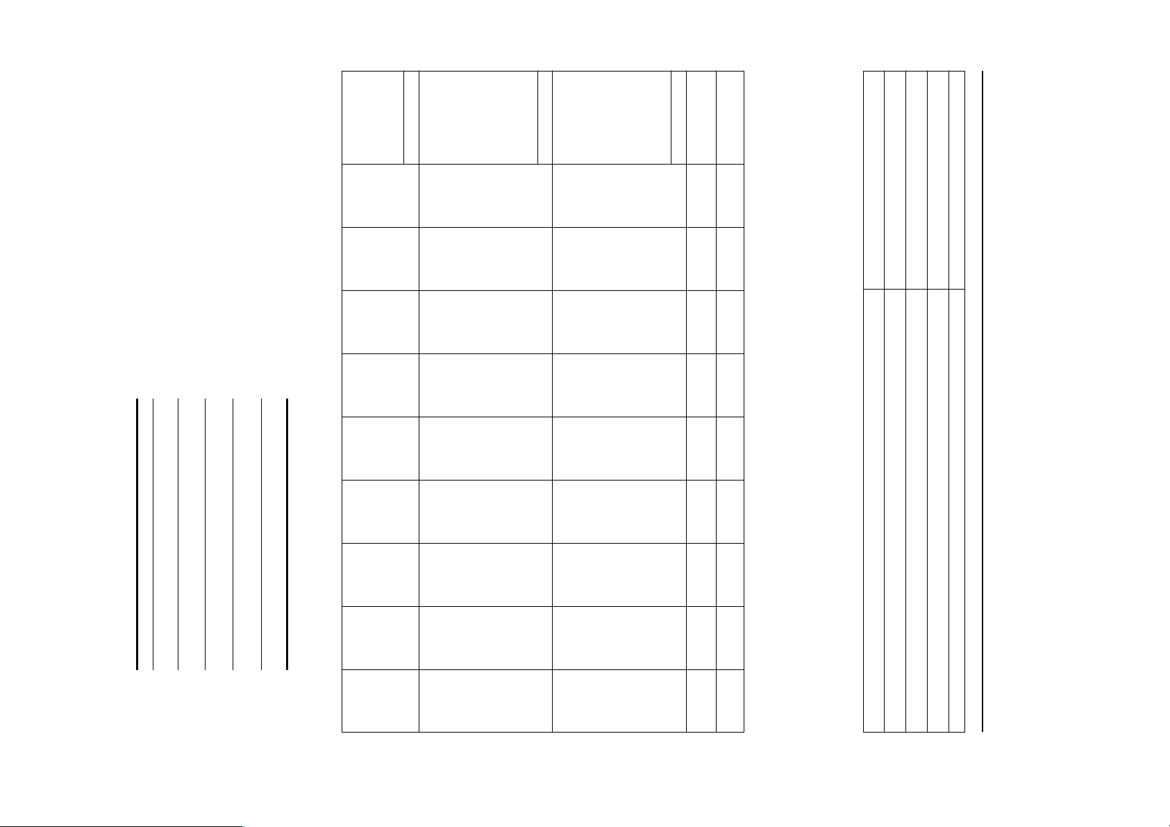
EXT(CS)/POLARITY NO NO NO NO NO NO NO NO NO
INT/NON INT NON INT NON INT NON INT NON INT NON INT NON INT NON INT NON INT NON INT
INT(G) NO NO NO NO NO NO NO NO NO
EXT(H/V)/POLARITY YES -/- YES -/- YES -/+ YES +/+ YES +/+ YES -/- YES +/+ YES +/+ YES +/+
V. BP 33 25 35 21 27 39 28 36 38
V. ACTIV 480 480 400 600 600 624 768 768 1024
— SYNC —
V. TOTAL 525 509 449 625 631 667 800 808 1066
V. BLK 45 29 49 25 31 43 32 40 42
V. FP 10112111111
V. SYNC 2 3 2 333333
H. ACTIV 25.422 17.778 25.422 16.162 14.222 14.524 13.003 10.836 11.852
— VERTICAL —
V. FREQ(HZ) 59.940 Hz 85.008 Hz 70.087 Hz 75.000 Hz 85.061 Hz 74.550 Hz 75.030 Hz 84.997 Hz 60.020 Hz
H. BP 1.907 2.222 1.907 3.232 2.702 3.910 2.235 2.201 2.296
H. SYNC 3.813 1.556 3.813 1.616 1.138 1.117 1.219 1.016 1.037
H. FP 0.636 1.556 0.636 0.323 0.569 0.559 0.203 0.508 0.444
H. BLK 6.356 5.333 6.355 5.172 4.409 5.586 3.657 3.725 3.778
H. TOTAL 31.778 23.111 31.777 21.333 18.631 20.111 16.660 14.561 15.630
CLOCK 25.175 MHz 36.000 MHz 28.322 MHz 49.500 MHz 56.250 MHz 57.283 MHz 78.750 MHz 94.500 MHz 108.000 MHz
— HORIZONTAL —
H-FREQ 31.469 kHz 43.269 kHz 31.469 kHz 46.875 kHz 53.674 kHz 49.725 kHz 60.024 kHz 68.677 kHz 63.981 kHz
RESOLUTION 640 X 480 640 X 480 720 X 400 800 X 600 800 X 600 832 X 624 1024 X 768 1024 X 768 1280 X 1024
TIMING SPECIFICATION
PRIMARY MODE
MODE AT PRODUCTION
CPD-E100/E100E
HV or +B Failure or H Stop Blink Amber (On 0.5 sec, Off 0.5 sec)
V Stop Blink Amber (On 1.5 sec, Off 0.5 sec)
ABL Failure Blink Amber (On 0.5 sec, Off 1.5 sec)
Aging/Self-Test Blink Amber (On 0.5 sec, Off 0.5 sec) .... Blink Green (On 0.5 sec, Off 0.5 sec)
DIAGNOSIS
– 2 –
(deep sleep)*
power off* 0 W off
3 active off**
≤ 5 W
2 supend
(sleep)*
≤ 15 W
S
TAR, and NUTEK. If the monitor is
Power mode Power
normal
operation
1 standby ≤ 15 W green and orange
consumption
≤ 95 W green
lines lines lines lines lines lines lines lines lines
usec usec usec usec usec usec usec usec usec
Failure Power LED
MODE 1 MODE 2 MODE 3 MODE 4 MODE 5 MODE 6 MODE 7 MODE 8 MODE 9
green and orange
alternate
orange
alternate
1 (power) indicator
99.7.2 VER.
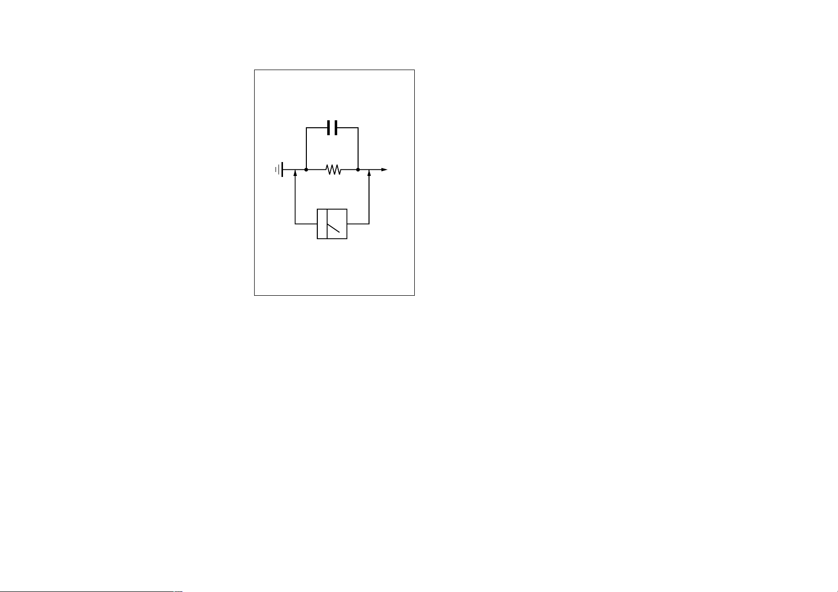
Fig. A. Using an AC voltmeter to check AC leakage.
0.15
µ
F
Parts on Set
To Exposed Metal
8. Check the antenna terminals, metal trim, “metallized”
Make sure your instruments are accurate; be suspicious of
your HV meter if sets always have low HV.
knobs, screws, and all other exposed metal parts for AC
Leakage. Check leakage as described below.
2. Check the interboard wiring to ensure that no wires are
6. Check the line cords for cracks and abrasion. Recommend
7. Check the B+ and HV to see if they are specified values.
the replacement of any such line cord to the customer.
5. Look for parts which, though functioning, show obvious
signs of deterioration. Point them out to the customer and
recommend their replacement.
4. Look for unauthorized replacement parts, particularly tran-
sistors, that were installed during a previous repair. Point
them out to the customer and recommend their replacement.
3. Check that all control knobs, shields, covers, ground straps,
“pinched” or contact high-wattage resistors.
and mounting hardware have been replaced. Be absolutely
certain that you have replaced all the insulators.
1. Check the area of your repair for unsoldered or poorly-sol-
dered connections. Check the entire board surface for solder
splashes and bridges.
After correcting the original service problem, perform the fol-
lowing safety checks before releasing the set to the customer:
– 3 –
Earth Ground
PROCEDURES WHENEVER CRITICAL COMPONENTS
ARE REPLACED OR IMPROPER OPERATION IS SUS-
NE JAMAIS METTRE SOUS TENSION QUAND LA
LES COMPOSANTS IDENTIFIÉS PAR UNE TRAME ET
UNE MARQUE
NE LES REMPLACER QUE PAR UNE PIÈCE PORTANT LE
NUMÉRO SPECIFIÉ. LES RÉGLAGES DE CIRCUIT DONT
L’IMPORTANCE EST CRITIQUE POUR LA SÉCURITÉ DU
FONCTIONNEMENT SONT IDENTIFIÉS DANS LE
PRÉSENT MANUEL. SUIVRE CES PROCÉDURES LORS
DE CHAQUE REMPLACEMENT DE COMPOSANTS CRI-
TIQUES, OU LORSQU’UN MAUVAIS FONCTIONNEMENT
EST SUSPECTÉ.
BOBINE DE DEMAGNETISATION EST ENLEVÉE.
PECTED.
ATTENTION AUX COMPOSANTS RELATIFS À LA
¡ SONT CRITIQUES POUR LA SÉCURITÉ.
AVERTISSEMENT!!
SÉCURITÉ!!
1.5 k
Ω
Voltmeter
AC
(0.75 V)
NEVER TURN ON THE POWER IN A CONDITION IN
COMPONENTS IDENTIFIED BY SHADING AND MARK
¡ ON THE SCHEMATIC DIAGRAMS, EXPLODED
VIEWS AND IN THE PARTS LIST ARE CRITICAL FOR
SAFE OPERATION. REPLACE THESE COMPONENTS
WITH SONY PARTS WHOSE PART NUMBERS AP-
PEAR AS SHOWN IN THIS MANUAL OR IN SUPPLE-
MENTS PUBLISHED BY SONY. CIRCUIT ADJUST-
MENTS THAT ARE CRITICAL FOR SAFE OPERATION
ARE IDENTIFIED IN THIS MANUAL. FOLLOW THESE
WHICH THE DEGAUSS COIL HAS BEEN REMOVED.
examples of a passive VOMs that are suitable. Nearly all
battery operated digital multimeters that have a 2 V AC
SAFETY-RELATED COMPONENT WARNING!!
range are suitable. (See Fig. A)
WARNING!!
2. A battery-operated AC milliammeter. The Data Precision
3. Measuring the voltage drop across a resistor by means of a
245 digital multimeter is suitable for this job.
VOM or battery-operated AC voltmeter. The “limit” indica-
tion is 0.75 V, so analog meters must have an accurate low-
voltage scale. The Simpson 250 and Sanwa SH-63Trd are
1. A commercial leakage tester, such as the Simpson 229 or
RCA WT-540A. Follow the manufacturers’ instructions to
use these instruments.
LEAKAGE TEST
The AC leakage from any exposed metal part to earth ground
and from all exposed metal parts to any exposed metal part hav-
ing a return to chassis, must not exceed 0.5 mA (500
microampers).
Leakage current can be measured by any one of three methods.
SAFETY CHECK-OUT
CPD-E100/E100E

– 4 –
CPD-E100/E100E
Section Title Page
1. GENERAL .................................................................. 1-1
3. SAFETY RELATED ADJUSTMENT............. 3-1
4. ADJUSTMENTS ...................................................... 4-1
5-2. Circuit Boards Location ...................................... 5-5
5-1. Block Diagrams ................................................... 5-1
5. DIAGRAMS
2-5. Harnes Location ................................................... 2-3
2-4. Picture Tube Removal .......................................... 2-2
2-3. H Board Removal ................................................. 2-1
7. ELECTRICAL PARTS LIST ............................ 7-1
6. EXPLODED VIEWS
6-2. Packing Materials ................................................ 6-2
6-1. Chassis ................................................................. 6-1
5-4. Semiconductors ................................................... 5-21
(3) Schematic Diagram of H Board .......................... 5-19
(2) Schematic Diagram of D Board .......................... 5-11
(1) Schematic Diagram of A Board ........................... 5-7
5-3. Schematic Diagrams and Printed Wiring Boards ...... 5-6
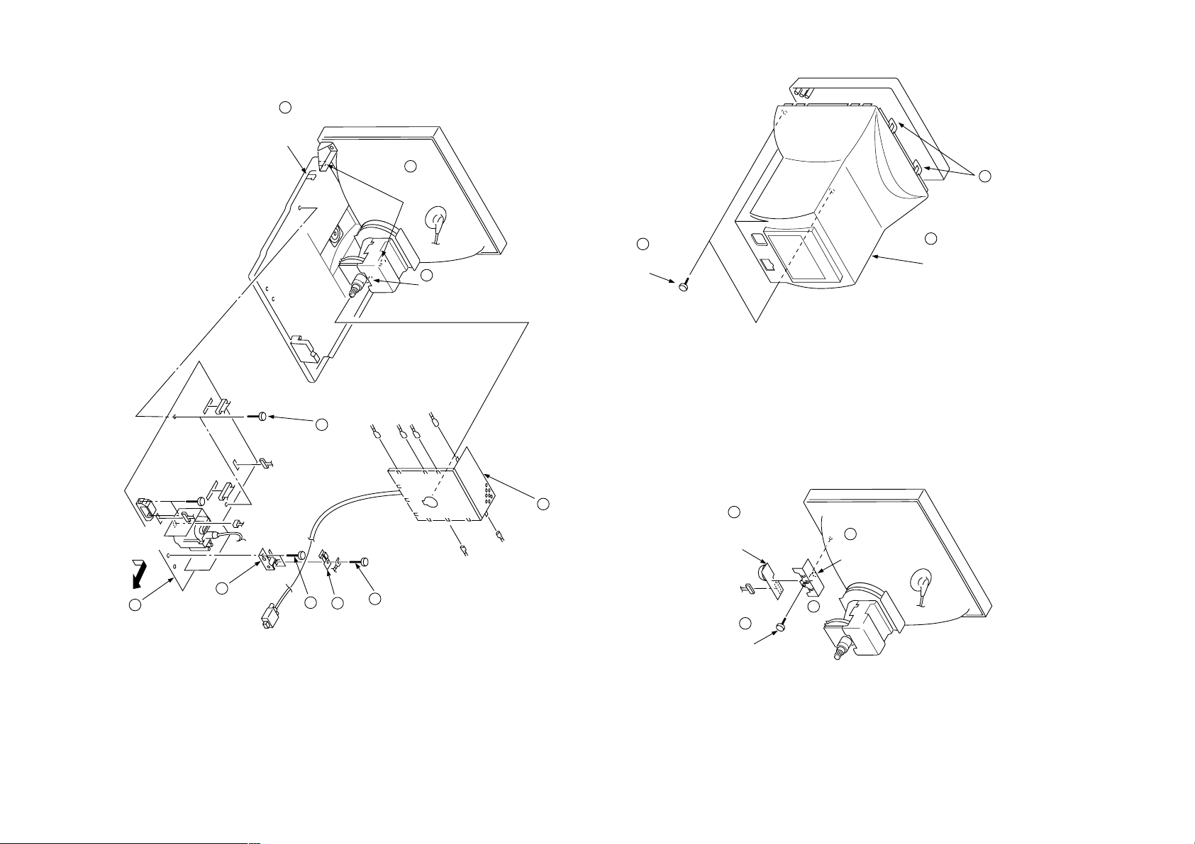
2. DISASSEMBLY
2-1. Cabinet Removal ................................................. 2-1
2-2. A and D Boards Removal ................................... 2-1
TABLE OF CONTENTS
CPD-E100/E100E
2-1
CN501
CN906
7
Claw
CN505
GND
6
Two screws
(+BVTP 3 x 12)
8
Two claws
GND
GND
7
Claw
GND
2-2. A AND D BOARDS REMOVAL
1
Two screws
(+BVTP 4 x 16)
3
Cabinet
2-1. CABINET REMOVAL
2
Two claws
DISASSEMBLY
SECTION 2
2-3. H BOARD REMOVAL
CN603
9
D board
CN502
5
Cable bracket
GND
4
3
Two screws
(+BVTP 3 x 12)
(+BVTT 4 x 8)
Cable stopper
2
Screw
GND
GND
1
A board
4
H board
P701
1
Screw
(+BVTP 3 x 12)
3
Claw
2
H bracket

• HOW TO HANDLE AN ANODE-CAP
1
2 Don’t press the rubber hardly not to damege inside of anode-caps!
3 Don’t turn the foot of rubber over hardly!
Don’t scratch the surface of anode-caps with shartp shaped mate-
rial!
A material fitting called as shatter-hook terminal is built in the
rubber.
The shatter-hook terminal will stick out or damage the rubber.
1
Turn up one side of the rubber cap in
the direction indicated by the arrow a.
a
• REMOVING PROCEDURES
2 Using a thumb pull up the rubber cap
firmly in the direction indicated by the
arrow b.
• REMOVAL OF ANODE-CAP
NOTE: Short circuit the anode of the picture tube and the anode cap to the metal chassis, CRT shield or carbon painted on the CRT,
after removing the anode.
11
Two degaussing
coil holders
Anode cap
1
Four screws
8
(Tapping screw 5)
Deflection yoke
6
Picture tube
7
2
A board
Neck assy
5
GND
GND
Demagnetic coil
9
2-4. PICTURE TUBE REMOVAL
2-2
b
3 When one side of the rubber cap is
separated from the anode button, the
anode-cap can be removed by turning
up the rubber cap and pulling up it in
the direction of the arrow c.
Anode Button
GND
GND
4
Bottom cover
(D board)
GND
GND
CN505
CN502
CN501
CN906
12
Two
degaussing
Cushion
c
coil holders
CN603
Two tension springs
10
3
Four screws
(+BVTP 4 x 16)
CPD-E100/E100E

2-3
A board
CN305
CN309
CN311
CN306
CN310
CN303
CN301 CN302
CN304
CN603
CN507
CPD-E100/E100E
2-5. HARNESS LOCATION
H board
CN504
B1B1B2
CN906
P701
D board
Picture tube
G
FBT
K
CN506
F
CN901
I
CN902
CN501
CN505
B2
HEAT SINK
G
CN502
I
Demagnetic coil

*
Protector Circuit
Check
Confirm one minute later turning on the power.
HV Hold-down
Circuit Check
Beam Current
HV Regulator
Circuit Check
HV ADJ
When replacing or repairing the shown below table, the
following operational checks must be performed as a
safety precaution against X-rays emissions from the unit.
3-1
• B+ Voltage Check
Standard voltage : 152 ± 5.0 V DC
Check Condition
• Input signal : White Cross hatch at 64.0 kHz
• Beam control : CONT : 255, BRT : 80
• Input voltage : 100 – 120 V AC
Note : Use NF power supply or make sure that
distortion factor is 3% or less.
below.
• Standard current : Less than 1.50 mA
Check Condition
• Input voltage : 100 – 120 V AC
• Input signal : White Cross hatch at Max fH
• Beam control : CONT : 255, BRT : 80
D board IC501, R598, R599,
D board T501 (FBT)
R596, RV501,
T501 (FBT)
T501 (FBT)
• Beam Current Protector Check
Connect a variable resistor (250 kΩ or more) and an am-
meter in series between FBT pin 1 on D board and
GND. Decrease gradually the resistance of the variable
resistor from maximum to minimum, and confirm that
the Beam Current Protector Circuite works (TV Raster
disappears). The current must be within the range shown
• Input signal : White Cross hatch at Max fH
• Beam control : CONT : 255, BRT : 80
D board IC502, IC503, Q511,
Part Replaced (])
D510, C535, R515,
R554, R559, R560,
appears)
Standard voltage : Less than 34 V DC
Check Condition
• Input voltage : 100 – 120 V AC
the HV HOLD DOWN circuite works. (TV Raster dis-
Part Replaced ([)
SAFETY RELATED ADJUSTMENT
RV501
SECTION 3
• HV Protector Circuit Check
Confirm that the voltage between cathode of D521 on D
board and GND is more than 28.5 V DC and Using ex-
ternal DC Power Supply, apply the voltage shown below
between cathode of D521 and GND, and confirm that
CPD-E100/E100E
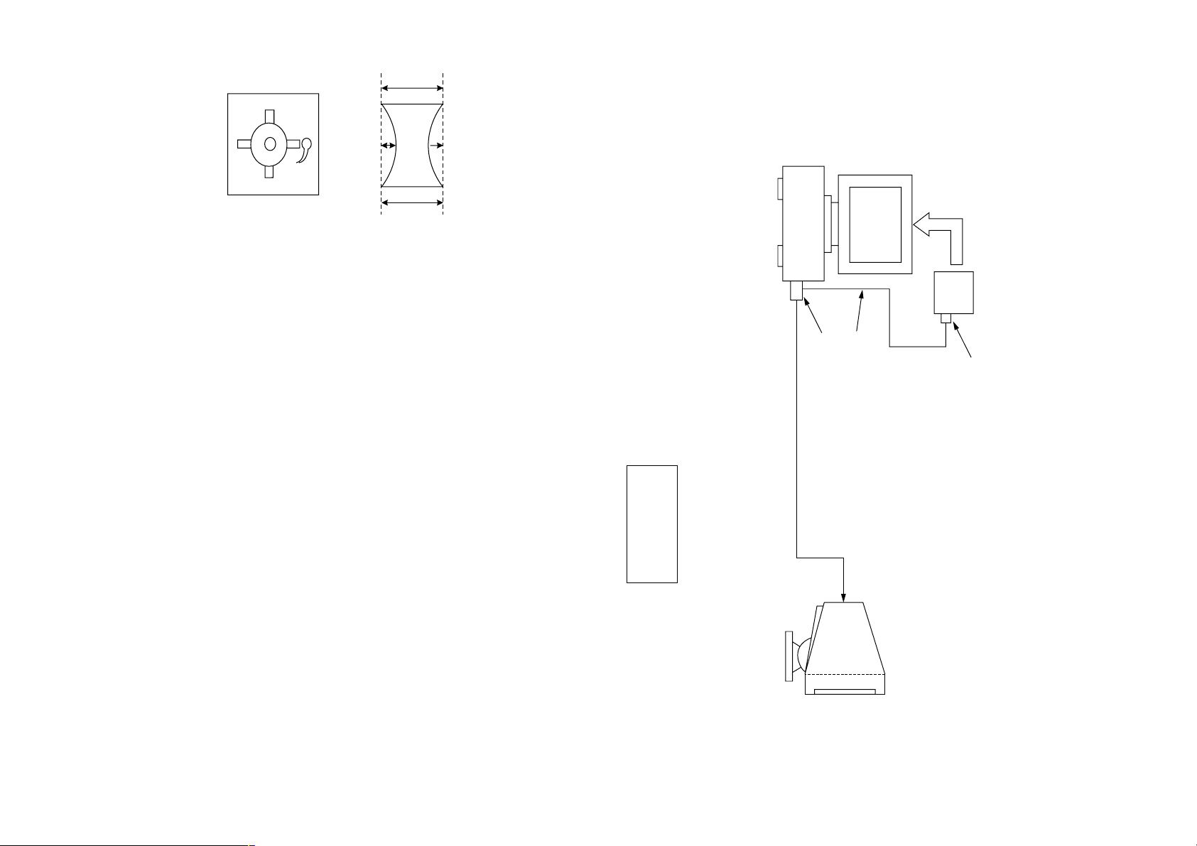
<How to drive in wedges>
cd
7. Adjust the DY position and purity, and the DY tilt.
8. Fasten DY with screw.
Note: Torque 20
9. Adjust top and bottom pins by pitching DY up and down
with two wedges.
Also leave the yaw of DY to physical center position with
Another two wedes.
6. Attach the sensor of the landing adjustment unit on the CRT
perform auto degaussing.
neck.
surface.
Purity magnet position
1. Put the set inside the Helmholtz coil.
2. Set TLH plate to zero position.
3. Input the single green signal.
4. Demagnetize the CRT surface with the hand degausser , and
5. Attach the wobbling coil to the designated part of the CRT
• Landing Fine Adjustment
CPD-E100/E100E
Connect the communication cable of the computer to the connector located on the D board on the monitor. Run the service software
and then follow the instruction.
4-1
b
a
“a” and “b” must be equal, and
“c” and “d” must be equal.
+2
-1
kgcm
10. If the corner landing is out of specification, put a disk mag-
11. Perform auto degauss in case disk magnets are used.
12. Remove the sensor and wobbling coil.
13. Fix purity magnet on DY with UL black tape.
net for the landing correction.
± 5 ± 7 ± 5
L/D control specification
± 5 ± 7 ± 5
± 5 ± 7 ± 5
Computer
as a Jig
I
HD15 Connector Adapter
2
C Interface Cable
Video Cable
I
2
C Interface Card
ADJUSTMENTS
SECTION 4
(µm)
 Loading...