

Page 1
3-867-817-12(1)
Micro Hi-Fi
Component
System
Operating Instructions
Owner’s Record
The model and serial numbers are located on the rear of the system. Record the serial
number in the space provided below. Refer to them whenever you call upon your Sony
dealer regarding this product.
Model No.
Serial No.
CMT-LS1
©1999 Sony Corporation
Page 2
WARNING
To prevent fire or shock hazard, do not
expose the unit to rain or moisture.
To avoid electrical shock, do not open the cabinet.
Refer servicing to qualified personnel only.
Do not install the appliance in a confined space,
such as a bookcase or built-in cabinet.
This appliance is
classified as a CLASS
1 LASER product. The
CLASS 1 LASER
PRODUCT
MARKING is located
on the rear exterior.
NOTICE FOR THE CUSTOMERS IN
THE U.S.A.
This symbol is intended to alert
the user to the presence of
uninsulated “dangerous voltage”
within the product’s enclosure
that may be of sufficient
magnitude to constitute a risk of
electric shock to persons.
This symbol is intended to alert
the user to the presence of
important operating and
maintenance (servicing)
instructions in the literature
accompanying the appliance.
CAUTION
The use of optical instruments with this product will
increase eye hazard.
The shielded interface cable recommended in this
manual must be used with this equipment in order to
comply with limits for a digital device pursuant to
Subpart B of Part 15 FCC Rules.
INFORMATION
This equipment has been tested and found to comply
with the limits for a Class B digital device, pursuant
to Part 15 of the FCC Rules. These limits are
designed to provide reasonable protection against
harmful interference in a residential installation. This
equipment generates, uses, and can radiate radio
frequency energy and, if not installed and used in
accordance with the instructions, may cause harmful
interference to radio communications. However, there
is no guarantee that interference will not occur in a
particular installation. If this equipment does cause
harmful interference to radio or television reception,
which can be determined by turning the equipment
off and on, the user is encouraged to try to correct the
interference by one or more of the following
measures:
– Reorient or relocate the receiving antenna.
– Increase the separation between the equipment and
receiver.
– Connect the equipment into an outlet on a circuit
different from that to which the receiver is
connected.
– Consult the dealer or an experienced radio/TV
technician for help.
CAUTION
You are cautioned that any changes or modifications
not expressly approved in this manual could void
your authority to operate this equipment.
Note to CATV system installer:
This reminder is provided to call CATV system
installer’s attention to Article 820–40 of the NEC that
provides guidelines for proper grounding and, in
particular, specifies that the cable ground shall be
connected to the grounding system of the building, as
close to the point of cable entry as practical.
NOTICE FOR THE CUSTOMERS IN
CANADA
CAUTION:
TO PREVENT ELECTRIC SHOCK, DO NOT USE
THIS POLARIZED AC PLUG WITH AN
EXTENSION CORD, RECEPTACLE OR OTHER
OUTLET UNLESS THE BLADES CAN BE FULLY
INSERTED TO PREVENT BLADE EXPOSURE.
2
Page 3

Table of Contents
Getting Started
Step 1: Hooking up the system ................ 4
Step 2: Setting the time ............................ 9
Step 3: Presetting radio stations ............. 10
Opening the front panel...........................11
Basic Operations
Playing a CD ........................................... 12
Listening to the radio .............................. 14
The CD Player
Playing the CD tracks in random order
— Shuffle Play ................................. 16
Programing the CD tracks
— Program Play ............................... 17
Playing the CD tracks repeatedly
— Repeat Play .................................. 18
Using the CD display .............................. 18
The Radio
Using the Radio Data System (RDS)
(European model only) ..................... 20
Timer
Falling asleep to music
— Sleep Timer ................................. 22
Waking up to music
— Daily Timer ................................. 23
Optional Components
Connecting audio components ................ 24
Listening to the sound of connected
components....................................... 25
Recording a CD on the connected
component ........................................ 26
Connecting external antennas ................. 26
Additional Information
Precautions .............................................. 27
Troubleshooting ...................................... 28
Specifications .......................................... 30
Index...........................................back cover
Sound Adjustment
Adjusting the sound ................................ 20
Generating a more dynamic sound..........21
Selecting the surround effect................... 21
3
Page 4
Getting Started
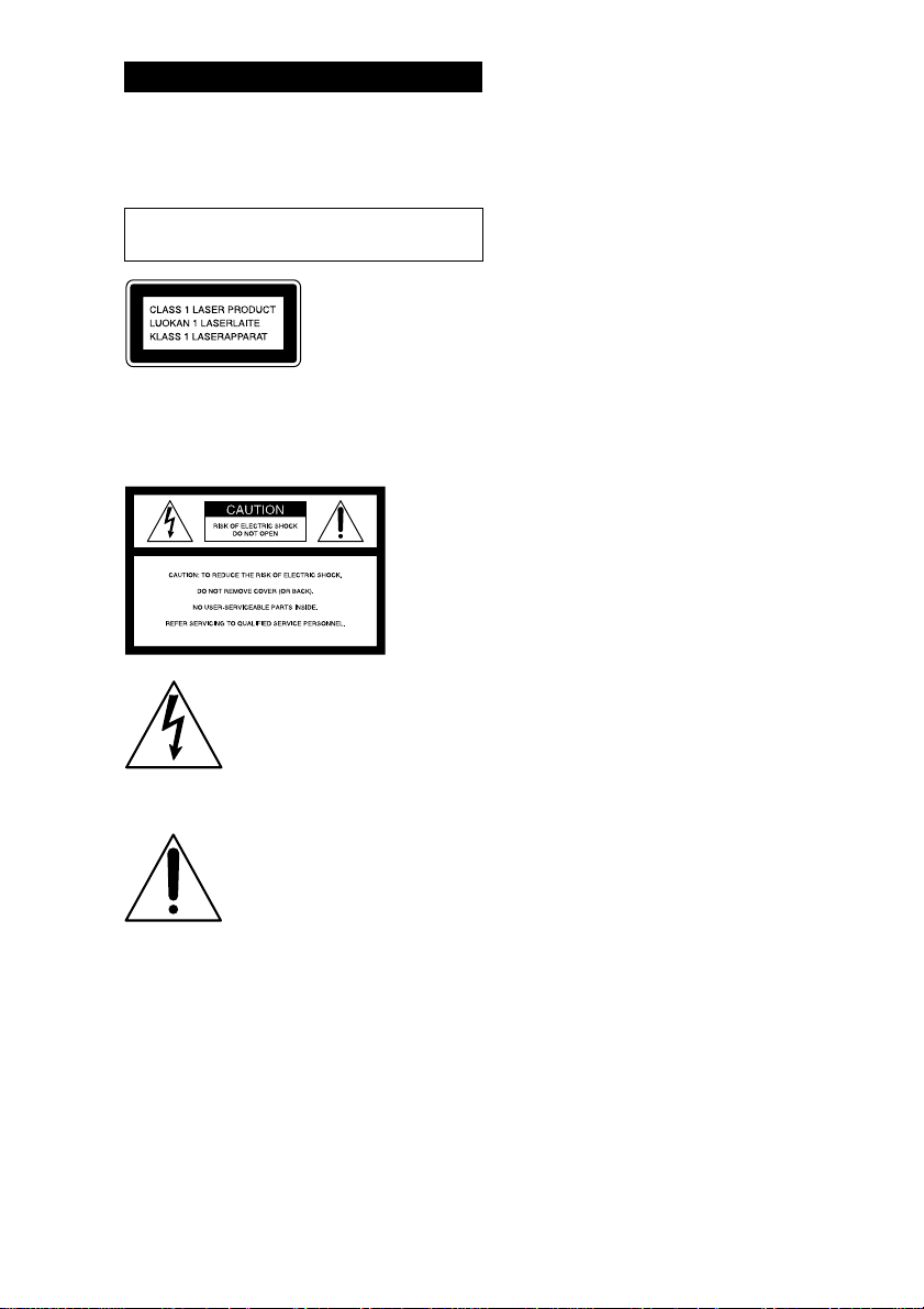
Step 1: Hooking up the system
Perform the following procedures 1 to 6 to hook up your system using the supplied cords and
accessories.
AM loop antenna
FM antenna
Left speakerRight speaker
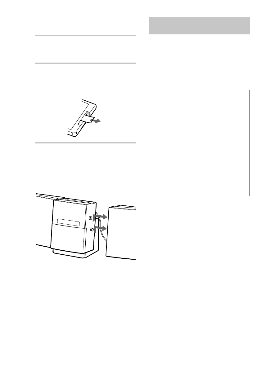
1 Attach the unit to the supplied desktop
stand with the supplied screws
(M4 × 14).
4
After mounting the unit on the stand, be
certain to pass the power cord through the
groove of the stand. If the stand is set up
without passing the power cord through the
groove, the weight of the unit will damage
the power cord, which could lead to electric
shock or fire.
Notes
• Be sure to attach the unit to the stand.
• Either mount both the left and right speakers, or
remove both of the speakers. Do not use the system
with only one speaker mounted.
Page 5
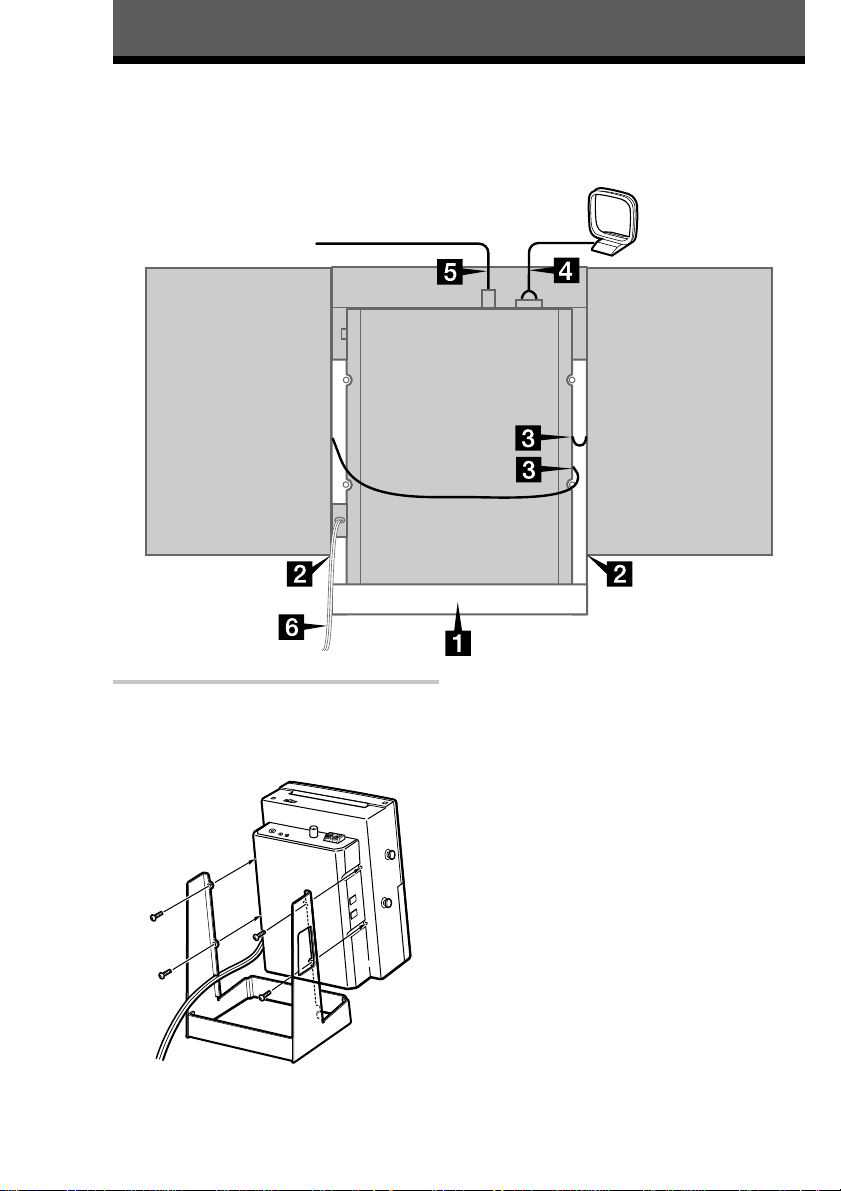
2 Attach the speakers.
Attach the speaker with the R cord to the
right side, and the speaker with the L cord to
the left side as viewed from the front of the
unit.
4 Connect the AM antenna.
Set up the AM loop antenna, then connect it.
Getting Started
AM loop antenna
Red
White
3 Connect the speakers.
Connect the speaker cords to the SPEAKER
jacks as shown below.
Notes
• Keep the speaker cords away from the antennas to
prevent noise.
• Be sure to connect both left and right speakers.
Otherwise, the sound will not be heard.
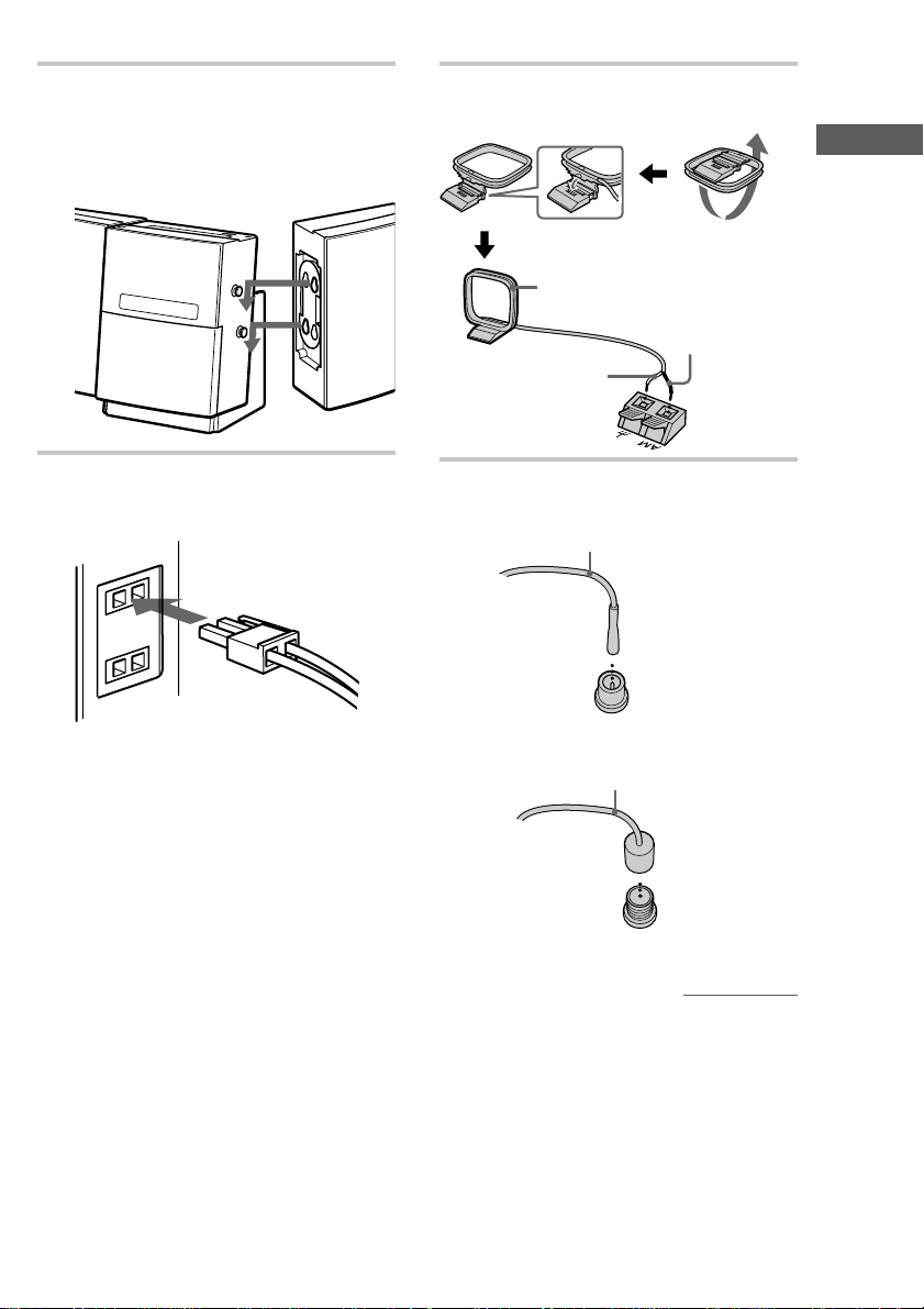
5 Connect the FM antenna.
Jack type A
Extend the FM lead antenna horizontally
Jack type B
Extend the FM lead antenna horizontally
continued
5
Page 6
Step 1: Hooking up the system
(continued)
6 Connect the AC power cord to a wall
outlet after you complete all the
connections.
7 To use the remote, pull out the
insulating sheet to allow power to flow
from the battery.
The remote already contains a battery.
To connect optional components
See “Optional Components” on page 24.
To detach the speakers
Slide the speakers in the direction of the arrows as
shown below.
Using the wall hanging
bracket
You can hang the unit on the wall using the
supplied wall hanging adapter and bracket.
The screws for attaching the wall hanging bracket
to the wall are not supplied. When installing the
bracket by yourself, be sure to use screws
appropriate for the type of wall. Sony cannot be
held responsible for any damages or injury due to
installation.
Safety precautions
• The supplied adapter and bracket are for use
with the Sony Compact Component System
CMT-LS1 only. Using these items for purposes
other than to hang the unit on the wall may
result in accidents.
• The component system CMT-LS1 (7.5 kg), the
wall hanging adapter (0.5 kg) and the wall
hanging bracket (0.5 kg) have a combined
weight of 8.5 kg. Therefore, for safety reasons,
the bracket should be attached securely to a wall
made from materials capable of supporting a
load of 50 kg or more.
• When you hang the unit on the wall, make sure
the left and right speakers are both attached or
both detached. Attaching one speaker without
the other may cause the unit to drop and injure
someone.
To protect the jacks on the top
of the unit from dust
Use the dust caps (supplied). See “Connecting
audio components” on page 24.
6
Preparation
• The screws for attaching the wall hanging
bracket to the wall are not supplied. Be sure to
purchase screws suited to the wall materials.
• If the wall materials cannot support a load of
50 kg or more, be sure to reinforce the wall.
Page 7
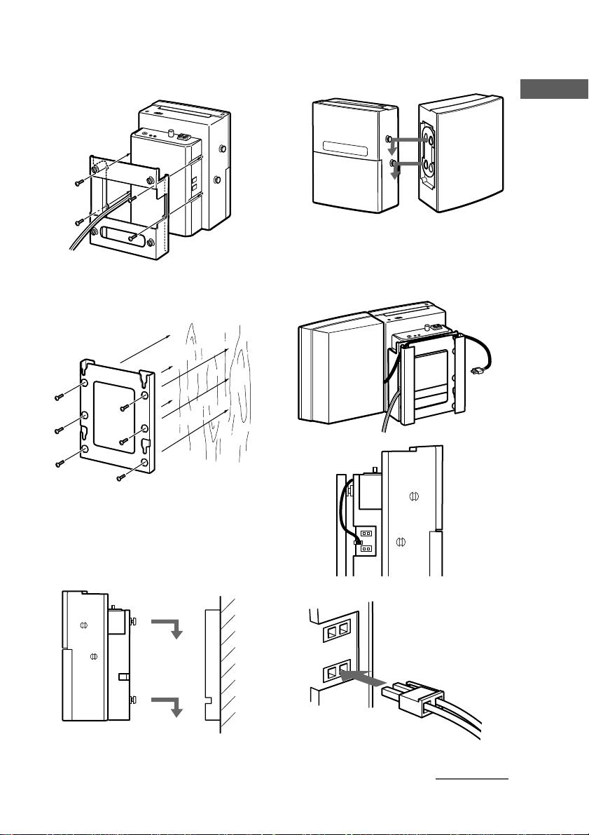
To hang the unit on the wall
1 Attach the wall hanging adapter to the
unit with the supplied screws (M4 × 14).
2 Fix the wall hanging bracket to the wall
using screws (not supplied).
4 Attach the speaker with the R cord to
the right side as viewed from the front
of the unit.
Getting Started
5 Connect the R cord to the SPEAKER
jack, pass the R cord through the groove
between the wall hanging adapter and
the bracket as shown below.
Note
Be sure to secure the bracket in a level
position.
3 Attach the wall hanging adapter to the
wall hanging bracket which you have
fixed to the wall.
continued
7
Page 8
Step 1: Hooking up the system
(continued)
6 Connect the L cord to the SPEAKER
jack as shown below.
7 Attach the speaker with the L cord to
the left side as viewed from the front of
the unit.
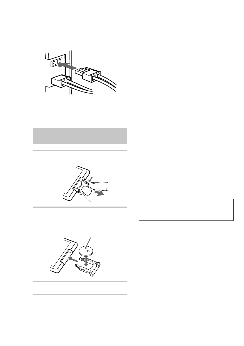
Replacing the battery in the
remote
1 Slide out and remove the battery case.
Battery life
You can expect the remote to operate for about
6 months (using a Sony CR2025 lithium battery)
before the battery run down. When the battery no
longer operates the remote, replace the battery
with a new one.
To avoid battery leakage
If you are not going to use the remote for a long
time, remove the battery to avoid damage caused
by corrosion from battery leakage.
Notes on lithium battery
• Keep the lithium battery out of the reach of
children.
Should the battery be swallowed, immediately
consult a doctor.
• Wipe the battery with a dry cloth to assure a
good contact.
• Be sure to observe the correct polarity when
installing the battery.
• Do not hold the battery with metallic tweezers,
otherwise a short-circuit may occur.
• Do not break up the battery or throw it into a
fire, which might cause it to explode.
Carefully dispose of the used battery.
CAUTION
Danger of explosion if battery is incorrectly replaced.
Replace only with the same or equivalent type
recommend by the manufacturer. Discard used
batteries according to the manufacturer’s instructions.
2 Insert a new lithium battery CR2025
with the + side facing up.
a lithium battery
CR2025
3 Slide the battery case back in.
8
WARNING
Battery may explode if mistreated.
Do not recharge, disassemble or dispose of in fire.
Page 9
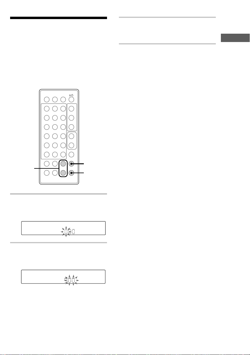
Step 2: Setting the time
You must set the time before you can use the
timer functions.
The clock is on a 24-hour system for the European
model, and a 12-hour system for other models.
The 24 hour system model is used for illustration
purposes.
Set the time before turning on the power.
31
2
564
8
97
10/0
>10
+
–
X
x
+
–
M
+
–
1
2,3
2,3
N
. >
m
3 Press +/– to set the minute then press
ENTER.
The clock starts.
Getting Started
To change the time
You can change the preset time while the power is
on.
1 Press CLOCK/TIMER SET.
2 Press +/– repeatedly until “SET CLOCK”
appears then press ENTER.
3 Repeat steps 2 and 3 of “Setting the time”.
Tips
• If you have made a mistake, start again from step 1.
• The built-in clock shows the time in the display
while the power is off.
• The upper dot flashes for the first half of a minute
(0 to 29 seconds), and the lower dot flashes for the
last half of a minute (30 to 59 seconds).
1 Press CLOCK/TIMER SET while the
power is off.
The hour indication flashes.
2 Press +/– to set the hour then press
ENTER.
The minute indication flashes.
9
Page 10
Step 3: Presetting radio stations
You can preset the following number of stations:
– 20 for FM, and 10 for AM.
5 Press MEMORY.
A preset number flashes.
Proceed to step 6 while the preset number is
flashing. If the unit is not operated for more
than 16 seconds, the preset number
disappears and the unit returns to the status
of step 3. If this happens, start over from
step 4.
1
31
2
564
8
97
10/0
>10
N
X
x
+
–
2
. >
m
M
+
–
1 Press ?/1 to turn on the power.
2 Press TUNER BAND repeatedly until
the band you want appears in the
display.
Each time you press the button, the band
changes as follows:
FM y AM
3 Press PLAY/TUNING MODE
repeatedly until “AUTO” appears.
3
5
+
–
4,6
6
6 Press TUNER +/– to select the preset
number you want, then press ENTER.
The station is stored.
7 Repeat steps 2 to 6 to preset other
stations.
To tune in the station manually
1 Press PLAY/TUNING MODE repeatedly until
“MANUAL” appears in step 3.
2 Press TUNER +/– repeatedly to tune in the
station and continue from step 5.
To change the preset number
Start over from step 2.
To change the AM tuning
interval (except for European
model)
The AM tuning interval is factory-set to 9 kHz
(10 kHz in some areas). To change the AM tuning
interval, tune in any AM station first. Turn off the
power while holding down the TUNER + button.
Then turn the power back on. When you change
the interval, all the AM preset stations are erased.
To reset the interval, repeat the same procedure.
4 Press TUNER +/–.
The frequency indication changes and
scanning stops when the system tunes in a
station. “TUNED” and “STEREO” (for a
stereo program) appear. When you want to
stop scanning, press PLAY/TUNING
MODE.
10
Page 11

Tip
The preset stations are retained for a day even if you
disconnect the AC power cord or if a power failure
occurs.
To erase a preset number
1 Press – on the remote in step 5 of “Presetting
radio stations”.
A preset number flashes.
2 Press TUNER +/– to select the preset number
you want to erase.
To erase all the preset numbers, select “ERA
ALL”.
3 Press ENTER.
The total number of preset stations decreases by
one each time you erase a preset number.
You can add new preset numbers after the last
preset number.
Opening the front panel
You can open the front panel automatically simply
by bringing your hand near the front panel. You
can also open and close the panel using the OPEN/
CLOSE button located on top of the unit. This
panel open setting is made using the PANEL
OPEN switch located on top of the unit.
You can select ON/AUTO, AUTO or MANUAL
using the PANEL OPEN switch located on top of
the unit.
PANEL OPEN switch
OPEN/CLOSE
Getting Started
continued
11
Page 12

Opening the front panel
(continued)
Basic Operations
Playing a CD
Switch setting Operation
ON/AUTO The power turns on and the
front panel opens when you
bring your hand near it while
the power is off. The panel
closes automatically if the unit
is not operated for more than
30 seconds.
AUTO
(factory setting)
The panel opens when you
bring your hand near it while
the power is on. The panel
closes automatically if the unit
is not operated for more than
30 seconds.
MANUAL The panel is opened and
closed by pressing OPEN/
CLOSE located on top of the
unit while the power is on.
Tip
Set the PANEL OPEN switch to MANUAL to leave
the panel open.
You can play up to 5 CDs in a row. To turn on the
power, press ?/1.
Open the front panel first to perform operations
using buttons on the unit. (See “Opening the front
panel” on page 11.)
?/1 (power)
NX
x
1
./>
m/M
VOLUME +/–
1
12
4
./>
m/M
?/1 (power)
31
2
564
8
10/0
N
>10
X
–
. >
m
97
x
+
M
+
–
x
X
+
–
3
DISC SKIP
VOL +/–
Page 13

1 Press DISC 1 – 5 to select a disc tray,
then press A on the unit.
2 Insert a CD and push it down lightly.
Note
You cannot play a 8 cm CD.
With the label side front
A box appears around the selected disc
number in the display when the disc is
loaded.
3 Press PLAY/TUNING MODE on the
remote repeatedly to select the playing
mode.
Each time you press the button, the mode
changes;
MODE Playing
ALL DISCS all the tracks on all CDs.
1 DISC all the tracks on the
ALL DISCS
SHUFFLE
1 DISC SHUFFLE all the tracks on the
DISC PROGRAM desired tracks on all CDs
current CD.
all the tracks on all CDs
in random order (see
page 16).
current CD in random
order (see page 16).
in the order you
programed (see page 17).
4 Press CD N (or NX on the unit).
Play starts and the playing disc number is
displayed.
Playing time
Getting Started/Basic Operations
Disc tray number Track number
To start playing a different CD, press
DISC 1 – 5 to select the desired disc.
To Do this
Stop play Press x.
Pause Press X (or NX on the
unit). Press again to resume
play.
Select a track Press . or > repeatedly
until you find the desired
track.
Find a point in a track Press and hold m or M
during play and release it at
the desired point.
Select a CD • Press DISC SKIP on the
remote repeatedly so that a
box appears around DISC 1
– 5 in the display. Press
CD N (or NX on the
unit) to play the selected
CD.
• Press DISC 1 – 5 on the
unit. Play starts when the
button is pressed.
If you press DISC 1 – 5 (or
DISC SKIP on the remote)
during play, the selected CD
changes and the new CD
starts playing.
Remove a CD Press DISC SKIP on the
remote repeatedly to select the
CD you want to remove. Open
the front panel and press A on
the unit.
Adjust the volume Press VOL +/–.
continued
13
Page 14

–
+
–
+
>10
10/0
8
97
564
2
31
m
M
–
+
x
. >
N
X
STEREO/
MONO
VOL +/–
1
3
2
Playing a CD (continued)
Tips
• You can switch from another source to the CD
player and start playing a CD by pressing CD N
(or NX on the unit) (Automatic Source
Selection).
• If you press CD N (or NX on the unit) while the
power is off, the power turns on and play starts
automatically (One Touch Play).
• The DISC 1 – 5 indicators light up in the display
when CD is loaded on the tray.
• If a CD is not loaded to any of DISC 1 – 5, “NO
DISC” appears.
• If you press a number button on the remote, the
track corresponding to the pressed number on the
current disc starts playing (Track Direct Play).
Listening to the radio
Preset radio stations in the tuner’s memory first
(see page 10). To turn on the power, press ?/1.
?/1 (power)
TUNER/BAND –/+
VOLUME +/–
14
?/1 (power)
Page 15

1 Press TUNER BAND repeatedly until
the band you want appears.
Each time you press the button, the band
changes as follows:
FM y AM
2 Press PLAY/TUNING MODE
repeatedly until “PRESET” appears.
3 Press TUNER +/– to select the desired
station’s preset number.
Preset number* and frequency
* When you preset only one station, “ONE
PRSET” appears in the display.
To Do this
Turn off the radio Press ?/1 to turn off the
power.
Adjust the volume Press VOL +/–.
To listen to non-preset radio
stations
• Press PLAY/TUNING MODE repeatedly until
“MANUAL” appears in step 2, then press
TUNER + or – repeatedly to tune in the desired
station (Manual Tuning).
• Press PLAY/TUNING MODE repeatedly until
“AUTO” appears in step 2, then press
TUNER + or –. The frequency indication
changes and scanning stops when the system
tunes in a station (Automatic Tuning).
To cancel the Automatic Tuning
Press PLAY/TUNING MODE.
Tips
• You can switch from another source to the tuner by
pressing TUNER BAND (Automatic Source
Selection).
• If you press TUNER BAND while the power is off,
the power turns on and the system tunes in the last
received station automatically (One Touch play).
• To improve broadcast reception, reorient the
supplied antenna or connect an optional external
antenna (FM antenna only).
• When an FM program has static noise, press
STEREO/MONO until “MONO” appears. There
will be no stereo effect, but the reception will
improve. Press again to restore the stereo effect.
Basic Operations
15
Page 16

The CD Player
Playing the CD tracks in
random order
You can play all the tracks on a CD or all CDs in
random order.
— Shuffle Play
1
31
2
564
8
97
10/0
>10
N
X
3
–
. >
m
x
+
M
+
–
1 Press FUNCTION repeatedly until
“CD” appears.
+
–
2
3
./>
3 If you select “ALL DISCS SHUFFLE”,
press CD N (or NX on the unit). If
you select “1 DISC SHUFFLE”, press
DISC SKIP repeatedly to select the
desired CD then press CD N (or just
press DISC 1 – 5 on the unit).
Shuffle Play starts.
To cancel Shuffle Play
Press PLAY/TUNING MODE repeatedly until
“SHUFFLE” and “PROGRAM” disappear from
the display. The tracks continue playing in their
original order.
Tips
• You can start Shuffle Play during normal play by
pressing PLAY/TUNING MODE repeatedly to
select “ALL DISCS SHUFFLE” or “1 DISC
SHUFFLE”.
• To skip a track, press >.
Press . to go back to the beginning of the
current track. However, you cannot go back to the
previous track.
2 Press PLAY/TUNING MODE
repeatedly to select the playing mode of
either “ALL DISCS SHUFFLE” or
“1 DISC SHUFFLE”.
MODE Playing
ALL DISCS SHUFFLE all the tracks on all
1 DISC SHUFFLE all the tracks on the
16
CDs in random
order.
current CD in
random order.
Page 17

Programing the CD
tracks
— Program Play
6 To program additional tracks, repeat
steps 3 to 5.
You can make a program up to 32 tracks.
You can make a program up to 32 tracks from all
the CDs in the order you want them to be played.
1
31
2
564
8
97
10/0
>10
N
X
7
4
–
. >
m
x
+
M
+
–
1 Press FUNCTION repeatedly until
“CD” appears.
2 Press PLAY/TUNING MODE
repeatedly until “DISC PROGRAM”
appears.
3 Press DISC SKIP repeatedly to select
the desired CD.
4 Press . or > repeatedly until the
desired track appears in the display.
5 Press PLAY/TUNING MODE.
The track is programed.
2,5
3
+
x
–
7 Press CD N.
All the programed tracks play in the order
you selected.
To cancel Program Play
Press PLAY/TUNING MODE repeatedly until
“PROGRAM” and “SHUFFLE” disappear from
the display.
To change the program
You can change the program before you start
playing.
To Do this
Clear the entire
program
Add a track to the
program
To select the desired track using
number buttons
Press number buttons instead of performing steps
4 to 6.
To enter track numbers 11 or over, press >10 once
and then the number buttons of the track number.
For example, to select track 32, press >10 once,
then 3, and 2.
Tips
• The program you made remains after Program Play
finishes. To play the same program again, press
CD N (or NX on the unit).
• “--.--” appears when the total playing time has
exceeded 100 minutes, or when you select a track
whose number is 21 or over.
• If you try to program 33 or more tracks, “FULL”
appears.
• You can also select a CD by using DISC 1 – 5 on
the unit in step 3.
Do steps 1 and 2 then press x
in stop mode.
Do steps 3 to 5.
The CD Player
17
Page 18

Playing the CD tracks
repeatedly
You can repeat a disc or all discs in normal play,
Shuffle Play and Program Play.
— Repeat Play
1
31
2
564
8
97
10/0
>10
N
X
x
+
–
. >
M
m
+
–
1 Press FUNCTION repeatedly until
“CD” appears.
2 Press REPEAT during play until
“REPEAT” or “REPEAT 1” appears.
REPEAT: For all the tracks.
REPEAT 1: For a single track only in normal
play.
2
+
–
Using the CD display
You can check the total number of tracks, the total
playing time, and the remaining time on the track
or the CD.
When a CD TEXT disc is loaded, you can check
the information stored on the CD, such as the titles
or artist names.
FUNCTION
31
2
564
8
97
10/0
>10
N
X
x
+
–
. >
M
m
+
–
DISPLAY
+
–
To cancel Repeat Play
Press REPEAT until “REPEAT” or “REPEAT 1”
disappears.
18
Page 19

Checking the total playing
time
1 Press FUNCTION repeatedly until
“CD” appears.
2 While the disc is stopped, press
DISPLAY repeatedly.
Each time you press the button, the display
changes as follows:
t The disc number and the track number
r
The disc title*
r
Artist name*
r
The total number of tracks and the total
playing time (The number of programed
tracks when programed)
r
Clock
* With CD TEXT discs only. When the CD
contains more than 20 tracks, CD TEXT is
not displayed beyond track 21.
Checking the remaining time
, Press DISPLAY repeatedly during play.
Each time you press the button, the display
changes as follows:
t The disc number, the track number and the
elapsed time of the current track
r
The disc number, the track number and the
remaining time*1 of the current track
r
The remaining time of the current CD*
r
The disc title of the current CD*
r
Clock
*1“--.--” is displayed when the CD contains
more than 20 tracks.
*2“--.--” is displayed in all modes except
1 DISC CONTINUE.
*3With CD TEXT discs only. When the disc
title has more than 31 characters, not all the
characters are displayed.
2
3
The CD Player
19
Page 20

The Radio
–
+
–
+
>10
10/0
8
97
564
2
31
m
M
–
+
x
. >
N
X
+/–
ENTER
BASS
TREBLE
Sound Adjustment
Using the Radio Data
System (RDS)
(European model only)
What is the Radio Data
System?
Radio Data System (RDS) is a broadcasting
service that allows radio stations to send
additional information along with the regular
program signal.
Note
RDS may not work properly if the station you have
tuned in is not transmitting the RDS signal properly
or if the signal is weak.
* Not all FM stations provide RDS service, nor do
they all provide the same types of services. If you
are not familiar with the RDS system, check with
your local radio stations for details on RDS services
in your area.
Receiving RDS broadcasts
Simply select a station from the FM band.
When you tune in a station that provides RDS
services, the station name appears in the display.
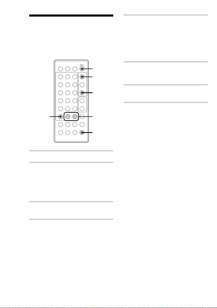
Adjusting the sound
You can adjust bass and treble.
Adjusting the bass
1 Press BASS.
2 Press +/– repeatedly until the level you
want appears.
You can adjust from –3 to +3.
To check the RDS information
Each time you press DISPLAY, the display
changes as follows:
Station name* y Frequency
* If the RDS broadcast is not properly received, the
station name may not appear in the display.
20
3 Press ENTER.
Adjusting the treble
1 Press TREBLE.
2 Press +/– repeatedly until the level you
want appears.
You can adjust from –3 to +3.
3 Press ENTER.
Page 21

Generating a more
Selecting the surround
dynamic sound
The Dynamic Sound Generator (DSG)
automatically enhances your music to produce a
more powerful sound.
31
2
564
8
97
10/0
>10
+
N
. >
m
DSG
, Press DSG.
Each time you press the button, the display
changes as follows:
DSG ON y DSG OFF
When DSG is ON, “DSG” lights up in the
display.
–
X
x
+
–
M
+
–
effect
You can enjoy the encompassing effects of
surround sound.
31
2
564
8
97
10/0
>10
+
X
–
. >
M
–
x
+
+
–
N
m
SURROUND
, Press SURROUND.
Each time you press the button, the display
changes as follows:
SURR ON y SURR OFF
When SURROUND is ON, “SURR” lights
up in the display.
The Radio/Sound Adjustment
To cancel DSG
Press DSG again to turn off “DSG”.
To cancel SURROUND
Press SURROUND again to turn off “SURR”.
21
Page 22

Timer
Falling asleep to music
— Sleep Timer
You can set the system to turn off after a certain
amount of time, so that you can fall asleep to
music. You can set the timer in 10 minutes
increments.
SLEEP
31
2
564
8
97
10/0
>10
+
X
–
. >
M
–
x
+
+
–
N
m
To check the remaining time
Press SLEEP once.
To change the remaining time
Press SLEEP repeatedly to select the time you
want.
To cancel Sleep Timer
Press SLEEP repeatedly until “OFF” appears.
Tip
You can use Sleep Timer, even if you have not set the
clock.
Note
When Sleep Timer is used, you cannot use Daily
Timer.
, Press SLEEP repeatedly to select a
desired time.
Each time you press the button, the minute
display (the remaining time) changes as
follows:
t OFF t AUTO* t 90M
...
10M T
After a few seconds, the previous display
appears. “SLEEP” and the timer indicator
light up in the display.
* When you select “AUTO”, the system
automatically turns off after the current CD
finishes playing (up to 100 minutes).
When the function is TUNER, the system
turns off in 100 minutes.
22
T 80M T
Page 23

Waking up to music
— Daily Timer
You can wake up to music at a preset time. Make
sure you have set the clock (see page 9).
To wake up to the radio, preset the radio stations
first (see page 10).
4 Press +/– repeatedly until
“SET DAILY” appears then press
ENTER.
The hour indication flashes.
5 Set the time to start playing.
Press +/– to set the hour, then press ENTER.
The minute indication flashes.
9
31
2
564
8
97
10/0
>10
+
2
–
X
x
+
–
M
+
–
CLOCK/
TIMER
SELECT
3
4–7
N
. >
m
4–8
1 Prepare the music source you want to
play.
• CD: Insert a CD. To start from a specific
track, make a program (see page 17).
• Radio: Tune in a preset radio station (see
page 14).
2 Press VOL +/– to adjust the sound
volume.
3 Press CLOCK/TIMER SET.
Press +/– to set the minute, then press
ENTER.
The hour indication flashes again.
6 Set the time to stop playing follow the
procedure in step 5.
7 Press +/– repeatedly until the music
source you want appears.
The indication changes as follows:
TUNER y CD PLAY
8 Press ENTER.
The start time, followed by the stop time, the
music source appears, then the original
display appears.
“DAILY” and the timer indicator light up in
the display.
9 Press ?/1 to turn off the power.
continued
Timer
23
Page 24

Waking up to music (continued)
To change the setting
Start again from step 1.
To check the setting / To use the
timer
Press CLOCK/TIMER SELECT repeatedly until
“DAILY” appears. The start time, followed by the
stop time, the music source appears, then the
original display appears.
To cancel Daily Timer
Press CLOCK/TIMER SELECT repeatedly until
“TIMER OFF” appears.
Tip
When you set Daily Timer, the system turns on
15 seconds before the preset time.
Optional Components
Connecting audio components
To enhance your system, you can connect optional
components. Refer to the instructions of each
component.
Connecting an MD deck for
digital recording
You can record from CD into the MD deck
digitally by connecting an optical cable (not
supplied).
To the DIGITAL IN jack of the MD deck
24
Connecting a tape deck
To listen to the sound of the connected tape deck,
press FUNCTION repeatedly until “TAPE”
appears.
To connect a tape deck to the system, use an audio
connecting cord with a stereo mini plug on one
end and RCA pin plugs on the other end.
Page 25

To the audio output of a tape deck
Listening to the sound of connected components
To the audio input of a tape deck
Connecting headphones
Connect headphones to the PHONES jack.
PHONES jack
Connecting the dust caps
When not connecting optional headphones or a
tape deck, attach the supplied dust caps to prevent
dust and dirt from entering the jacks. You can also
cut apart the supplied caps and use each one
separately.
2
31
2
564
8
97
10/0
>10
+
X
–
. >
M
–
x
+
+
–
N
m
1 Prepare the audio components.
2 Press FUNCTION repeatedly until
“TAPE” appears.
Each time you press the button, the function
display changes as follows:
t TUNER t TAPE t CD
Timer/Optional Components
25
Page 26

Recording a CD on the
Connecting external
connected component
For the operations of the connected components,
refer to the instructions of each component.
2
31
2
564
8
97
10/0
>10
+
X
–
. >
M
–
x
+
+
–
4
N
m
1 Prepare the recording component for
recording.
2 Press FUNCTION repeatedly until
“CD” appears.
antennas
Connect an external antenna to improve the
reception. Refer to the instructions of each
component.
FM antenna
Connect an optional FM external antenna.
You can also use the TV antenna instead.
Jack type A
75-ohm coaxial
cable (not
supplied)
3 Start recording on the MD deck or the
tape deck.
4 Press CD N.
Play starts.
26
75-ohm coaxial
cable (not
supplied)
Page 27

AM antenna
Connect a 6- to 15- meter (20- to 50- feet)
insulated wire to the AM antenna terminal.
Leave the supplied AM loop antenna connected.
Insulated wire (not supplied)
Important
If you connect an external antenna, connect the
ground wire to the U terminal. To prevent a gas
explosion, do not connect the ground wire to a gas
pipe.
Additional Information
Precautions
On safety
• The system is not disconnected from the AC power
source (mains) as long as it is connected to the wall
outlet, even if the system itself has been turned off.
• Unplug the system from the wall outlet if it is not to
be used for an extended period of time. To
disconnect the cord (mains lead), pull it out by the
plug. Never pull the cord itself.
• Should any solid object or liquid fall into the
system, unplug the system and have it checked by
qualified personnel before operating it any further.
• The AC power cord must be changed only at the
qualified service shop.
• When you connect the AC power cord to the wall
outlet (mains), even though the power is off, the
system begins charging for remote and timer
functions. Therefore the surface of this unit
becomes warm, this is normal.
• The nameplate indicating operating voltage, power
consumption, etc. is located at the rear.
On placement
• Place the system in a location with adequate air
circulation, and do not place anything on the
system.
• Place the system in a location with adequate
ventilation to prevent heat build up.
• Do not place the system in an inclined position.
• Do not place the system in locations where it is;
— Extremely hot or cold
— Dusty or dirty
— Very humid
— Subject to vibrations
— Subject to direct sunlight.
On installing
When you move the system, remove all discs.
Optional Components/Additional Information
continued
27
Page 28

Precautions (continued)
On operation
• You cannot play 8 cm CDs with this system.
• If the system is brought directly from a cold to a
warm location, or is placed in a very damp room,
moisture may condense on the lens inside the CD
player. Should this occur, the system will not
operate properly. Remove the CD and leave the
system turned on for about 2 hours until the
moisture evaporates.
Troubleshooting
If you have any problem using this system, use the
following checklist.
First, check that the AC power cord is connected
firmly and that the speakers are connected
correctly and firmly.
Should any problem persist, consult your nearest
Sony dealer.
If you have any questions or problems concerning
your system, please consult your nearest Sony dealer.
On the speaker system
This speaker system is not magnetically shielded and
the picture on TV sets may become magnetically
distorted. In such a case, turn off the power of the TV
set once, and after 15 to 30 minutes turn it on again.
If there seems to be no improvement, locate
the speaker system further away from the TV set.
Also, be sure not to place objects in which magnets
are attached or used near the TV set, such as audio
racks, TV stands and toys. These may cause magnetic
distortion to the picture due to their interaction with
the system.
Notes on CDs
• Do not use a CD with tape, stickers, or paste on it as
this may damage the player.
• Before playing, clean the CD with a cleaning cloth.
Wipe the CD from the center out. Do not use
solvents such as benzine, thinner, commercially
available cleaners, or antistatic spray intended for
vinyl LPs.
• Do not expose the CD to direct sunlight or heat
sources such as hot air ducts, nor leave it in a car
parked in direct sunlight.
Cleaning the cabinet
Use a soft cloth slightly moistened with mild
detergent solution.
General
There is no sound.
• Press VOLUME +.
• Make sure the headphones are not connected.
• Check the speaker connections.
There is severe hum or noise.
• A TV or VCR is placed too close to the
system. Move the system away from the TV
or VCR.
“0:00” (or “12:00AM”) flashes in the
display.
• A power failure occurred. Set the clock and
timer settings again.
The timer does not function.
• Set the clock correctly.
The remote does not function.
• There is an obstacle between the remote and
the system.
• The remote is not pointing in the direction of
the system’s sensor.
• The battery have run down. Replace the
battery.
• Do not place the system in locations where it
is near an electric inverter system.
The front panel does not open when you
bring your hand near.
• The PANEL OPEN switch is set to
MANUAL. Set the switch to ON/AUTO or
AUTO.
28
Page 29

CD Player
Tuner
The CD will not eject.
• The CD has tape, stickers, or paste on it.
The CD will not play.
• The CD is dirty. Clean the CD with a
cleaning cloth.
• The face of the CD is scratched. Exchange the
CD.
• The CD is facing the wrong way.
• Moisture condensation has built up. Remove
the CD and leave the system turned on for
about 2 hours until the moisture evaporates.
Play does not start from the first track.
• The player is in program or shuffle mode.
Press PLAY/TUNING MODE repeatedly
until “SHUFFLE” and “PROGRAM”
disappear.
“OVER” is displayed.
• By pressing M, the last track on the disc has
been exceeded. Press and hold (or press
repeatedly) . or m to return to a track
where playing can begin.
Severe hum or noise (“TUNED” or
“STEREO” flashes in the display).
• Adjust the antenna.
• The signal strength is too weak. Connect an
external antenna.
• Make sure the antenna is connected properly.
• Make sure the antenna is not folded or rolled
up.
A stereo FM program is not received in
stereo.
• Press STEREO/MONO so “STEREO”
appears.
If other problems not described
above occur, reset the system
as follows:
1 Unplug the AC power cord.
2 Hold down ?/1, then plug the AC power cord
into the wall outlet again.
The system is reset to the factory settings. All the
settings you made, such as the preset stations,
clock, and timer are cleared. You should set them
again.
Additional Information
29
Page 30

Specifications
Amplifier section
For the U.S. model
AUDIO POWER SPECIFICATIONS
POWER OUTPUT AND TOTAL HARMONIC
DISTORTION:
With 4 ohm loads both channels driven, from 120
– 10,000 Hz; rated 16 watts per channel minimum
RMS power, with no more than 0.9% total
harmonic distortion from 250 milliwatts to rated
output.
North American model:
Continuous RMS power output (Reference)
European model:
DIN power output (Rated) 11 + 11 watts
Continuous RMS power output (Reference)
Other models:
DIN power output (Rated) 11 + 11 watts
Continuous RMS power output (Reference)
Inputs TAPE IN (stereo mini jack):
Outputs TAPE OUT (stereo mini jack):
16 + 16 watts
(4 ohms at 1 kHz, 10% THD)
(4 ohms at 1 kHz, DIN)
16 + 16 watts
(4 ohms at 1 kHz, 10% THD)
(4 ohms at 1 kHz, DIN, 240 V)
11 + 11 watts
(4 ohms at 1 kHz, DIN, 220 V)
16 + 16 watts
(4 ohms at 1 kHz, 10% THD,
240 V)
16 + 16 watts
(4 ohms at 1 kHz, 10% THD,
220 V)
voltage 250 mV, impedance
47 kilohms
1Vrms at CD Full Bit Play,
impedance 1 kilohm
CD OUT: Optical
PHONES (stereo mini jack):
accepts headphones of 8 ohms or
more
SPEAKER: speaker system
4 ohms
CD player section
System Compact disc and digital audio
Laser Semiconductor laser (λ=780 nm)
Laser output Max. 44.6 µW*
Frequency response 20 Hz – 20,000 Hz (±3.0 dB)
system
Emission duration: continuous
*This output is the value measured
at a distance of 200 mm from the
objective lens surface on the
Optical Pick-up Block with 7 mm
aperture.
Tuner section
FM stereo, FM/AM superheterodyne tuner
FM tuner section
Tuning range
North American model: 87.5 – 108.0 MHz (100 kHz step)
Other models: 87.5 – 108.0 MHz (50 kHz step)
Antenna FM lead antenna
Antenna terminals 75 ohms unbalanced
Intermediate frequency 10.7 MHz
AM tuner section
Tuning range
North American model: 530 – 1,710 kHz
European model: 531 – 1,602 kHz
Other models: 531 – 1,602 kHz
Antenna AM loop antenna
Intermediate frequency 450 kHz
(with the interval set at 10 kHz)
531 – 1,710 kHz
(with the interval set at 9 kHz)
(with the interval set at 9 kHz)
(with the interval set at 9 kHz)
530 – 1,710 kHz
(with the interval set at 10 kHz)
30
Page 31

Speaker
Speaker system 2-way, bass-reflex type
Speaker units
Woofer: 10 cm dia., cone type
Tweeter: 2.5 cm dia., balanced drive
Impedance 4 ohms
Dimensions 194 × 251 × 73 mm
Mass Approx. 1.8 kg net per speaker
(w/h/d, incl. projecting parts and
controls)
Desktop stand
Dimensions (w/h/d) 184 × 218 × 140 mm
Mass Approx. 0.5 kg
Wall hanging adapter
Dimensions (w/h/d) 180 × 220 × 39 mm
Mass Approx. 0.5 kg
Wall hanging bracket
Dimensions (w/h/d) 180 × 220 × 12 mm
Mass Approx. 0.4 kg
General
Power requirements
North American model: 120 V AC, 60 Hz
European model: 230 V AC, 50/60 Hz
Other models: 220 – 240 V AC, 50/60 Hz
Power consumption 25 W
Dimensions 192 × 295 × 150 mm
Mass Approx. 4.0 (with Desktop
Supplied accessories Remote commander (1)
(w/h/d, incl. projecting parts,
controls and desktop stand)
stand) kg
AM loop antenna (1)
FM wire antenna (1)
Desktop stand (1)
Wall hanging adapter (1)
Wall hanging bracket (1)
Screws for stand or adapter
M4 × 14 (4)
Dust caps (3)
Designs and specifications are subject to change
without notice.
Additional Information
31
Page 32

Index
A
Adjusting
the sound 20
the volume 13, 15
Antennas 5, 26
Automatic Source Selection
14, 15
Automatic Tuning 10, 15
B
Battery 6, 8
C
CD player 16
Clock setting 9
Connecting. See Hooking up
D, E, F, G
Daily Timer 23
Desktop stand 4
Display 18
DSG (Dynamic Sound
Generator) 21
L
Listening to
the radio 14
the sound of connected
components 25
M
Manual Tuning 10, 15
N
Normal Play 13
O
One Touch Play 14, 15
Opening the front panel 11
P, Q
Playing
a CD 12
tracks in random order
(Shuffle Play) 16
tracks in the desired order
(Program Play) 17
tracks repeatedly
(Repeat Play) 18
Presetting radio stations 10
Program Play 17
R
Radio stations
presetting 10
tuning in 15
RDS 20
Recording a CD 26
Repeat Play 18
Resetting the system 29
S
Setting the time 9
Shuffle Play 16
Sleep Timer 22
Sound adjustment 20
Speakers 5, 6
Surround effect 21
T, U, V, W, X, Y, Z
Timer
falling asleep to music 22
waking up to music 23
Track Direct Play 14
Troubleshooting 28
Tuner 10, 15
Tuning interval 10
H, I, J, K
Hanging the unit on the wall 6
Hooking up
optional components 24
the antennas 5, 26
the speaker 5
Sony Corporation Printed in Malaysia
 Loading...