

Sony CFMA-50 Service manual
CFM-A50
SERVICE MANUAL
Ver. 1.2 2005.06
SPECIFICATIONS
Radio section
Frequency range
FM 87.6 – 108MHz (US model)
FM 87.6 – 107MHz (AEP, UK model)
AM 530 – 1,710kHz (US model)
MW 531 – 1,602kHz (AEP, UK model)
LW 153 – 279kHz (AEP, UK model)
Aerials
FM : Telescopic aerial
AM : Built-in ferrite bar aerial
Cassette-corder section
Recording system
2-track 1channel monaural
Fast winding time
Approx. 120 s (sec.) with Sony cassette C-60
Frequency response
TYPE I (normal) : 100 – 8,000Hz
General
Speaker
Full range : 9.2cm dia.,4 ohms, cone type (1)
Output
Earphone jack (minijack)
For 32 ohms impedance earphone
US Model
AEP Model
UK Model
Model Name Using Similar Machanism NEW
Tape Transport Mechanism Type MF-A50-117
Maximum power output
2.3 W
Power requirements
120V AC, 60Hz (US model)
230V AC, 50Hz (AEP, UK model)
6V DC, four R20 (size D) batteries
Power consumption
AC 6W
Battery life
FM recording
Sony R20P : approx. 13h
Sony alkaline LR20 : approx. 35h
Tape playback
Sony R20P : approx. 7h
Sony alkaline LR20 : approx. 20h
Dimensions
Approx. 289 x 200 x 123 mm (w/h/d)
(111/2 x 7 7/8 x 4 7/8 inches) (incl. projecting parts)
Mass
Approx. 2.4 kg (5 lb. 5 oz) (incl. batteries)
Supplied accessory
AC power cord (1)
Earphone (1)
Design and specifications are subject to change without notice.
9-923-167-14
2005F02-1
© 2005.06
RADIO CASSETTE-CORDER
Sony Corporation
Personal Audio Group
Published by Sony Engineering Corporation
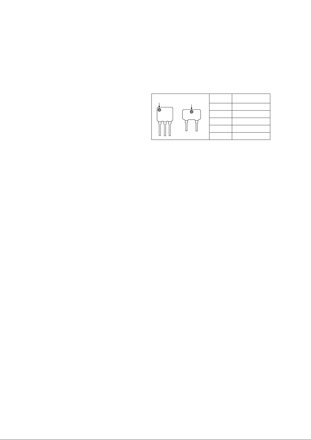
TABLE OF CONTENTS
Specifications ........................................................................... 1
1. GENERAL
Location and Function of Controls .................................... 3
2. DISASSEMBLY
2-1. Cabinet (Rear) Removal ............................................. 4
2-2. ISS SW Board, Battery Case,
BATTERY Board, POWER Board Removal ............. 4
2-3. Main Board, TUN LED Board,
TACT SW Board Removal ........................................ 5
2-4. H/P JACK Board, Door Ear (PH),
Box Ear (PH) Removal ............................................... 5
2-5. Mechanism Deck, DECK CONTROL Board
Volume Board Removal .............................................. 6
3. DIAL POINTER SETTING......................................... 7
4. ADJUSTMENTS
4-1. Mechanical Adjustment .............................................. 8
4-2. Electrical Adjustment ................................................. 8
5. DIAGRAMS
5-1. Schematic Diagram (AEP,UK Model)...................... 12
5-2. Printed Wiring Boards (AEP,UK Model) ................. 15
5-3. Printed Wiring Boards (US Model).......................... 19
5-4. Schematic Diagram (US Model) .............................. 23
HOW TO CHANGED THE CERAMIC FILTERS
This model is used three ceramic filters of CF2, CF4 and CF3.
You must used same type of color marked ceramic filters in order
to meet same specifications.
Therefore, the ceramic filter must changed three pieces together
since it's supply three pieces in one package as a spare parts.
mark
CF2, 4
SAFETY-RELATED COMPONENT WARNING!!
COMPONENTS IDENTIFIED BY MARK ! OR DOTTED LINE WITH
MARK ! ON THE SCHEMATIC DIAGRAMS AND IN THE PARTS
LIST ARE CRITICAL TO SAFE OPERATION.
REPLACE THESE COMPONENTS WITH SONY PARTS WHOSE
PART NUMBERS APPEAR AS SHOWN IN THIS MANUAL OR IN
SUPPLEMENTS PUBLISHED BY SONY.
mark
CF3
Mark
red
blue
orange
black
white
Center
fequency
10.70MHz
10.67MHz
10.73MHz
10.64MHz
10.76MHz
6. EXPLODED VIEWS
6-1. Cabinet (Rear) Section.............................................. 28
6-2. Cabinet (Front) Section ............................................ 29
6-3. Mechanism Deck Section-1 (MF-A50-117)............. 30
6-4. Mechanism Deck Section-2 (MF-A50-117)............. 31
7. ELECTRICAL PARTS LIST.................................... 32
– 2 –
SECTION 1
GENERAL
SAFETY CHECK-OUT
After correcting the original service problem, perform the following safety check before releasing the set to the customer :
Check the antenna terminals, metal trim, “metallized” knobs, screws,
and all other exposed metal parts for AC leakage. Check leakage as
described below.
LEAKAGE TEST
The AC leakage from any exposed metal part to earth ground and
from all exposed metal parts to any exposed metal part having a
return to chassis, must not exceed 0.5mA (500 microampers).
Leakage current can be measured by any one of three methods.
1. A commercial leakage tester, such as the Simpson 229 or RCA
WT-540A. Follow the manufacturers’ instructions to use these
instruments.
2. A battery-operated AC milliammeter. The Data Precision 245
digital multimeter is suitable for this job.
3. Measuring the voltage drop across a resistor by means of a VOM
or battery-operated AC voltmeter. The “limit” indication is
0.75V , so analog meters must have an accurate low-voltage scale.
The Simpson 250 and Sanwa SH-63Trd are examples of a passive VOM that is suitable. Nearly all battery operated digital
multimeters that have a 2V AC range are suitable. (See Fig. A)
To Exposed Metal
Parts on Set
µ
0.15 F
Fig. A. Using an AC voltmeter to check AC leakage.
1.5kΩ
Earth Ground
AC
voltmeter
(0.75V)
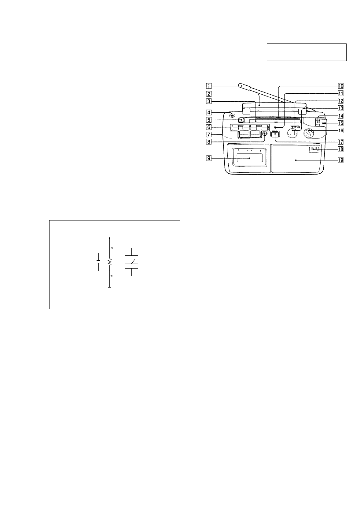
This section is extracted from
instruction manual.
LOCATION AND FUNCTION OF CONTROLS
1 FM telescopic aerial
2 Carrying handle
3 Dial scale
4 @ (earphone) jack (mini jack)
5 LIGHT (Dial scale light) button
6 Tape operation buttons
7 EARPHONE POCKET box
8 SLOW PLAYBACK button
9 Cassette compartment lid
!º Frequency marker
!¡ OPR/BATT indicator
!™ EASY LISTENING ADJUSTMENT switch
!£ EASY LISTENING ADJUSTMENT control
!¢ BAND switch
!∞ TUNING control
!§ VOLUME control
!¶ FUNCTION switch
!• Built-in microphone
!ª Speaker
– 3 –
e
Ver 1.1 2001.11
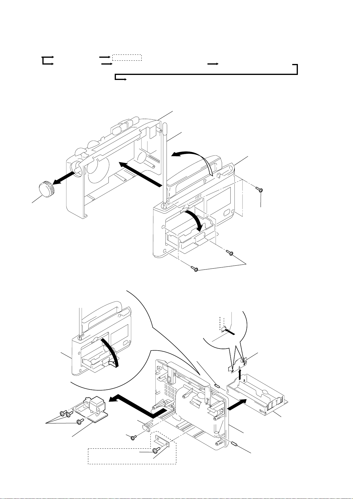
SECTION 2
DISASSEMBLY
z
The equipment can be removed using the following procedure.
Set
Cabinet (Rear) assy
Cabinet (Front) assy
Note : Follow the disassembly procedure in the numerical order given.
2-1. CABINET (REAR) REMOVAL
5
AEP, UK model
ISS SW board , BATTERY CASE, BATTERY board, POWER board
Main board, TUN LED board, TACT SW board
Mechanism deck, DECK CONTROL board, VOLUME board
4
H/P JACK board, DOOR EAR (PH),
BOX EAR (PH)
Cabinet (Front) assy
ANT1
1
Cabinet (Rear) assy
Knob, TU
3
2 Screws (+BV 3X14)
2-2. ISS SW BOARD, BATTERY CASE, BATTERY BOARD, POWER BOARD REMOVAL
7
Cabinet (Rear) assy
2
6 Shaft, handle
8
2 Screws (+BV 3X14)
BATTERY board
9 Screw
(+BV 3x10)
Power board
Stoper, wire
3 Screw
(+BV 3x10)
AEP, UK model
1 Screws (+BV 3x10)
0
ISS SW board
– 4 –
5
Cabinet (Rear) assy
4 Shaft, handle
Battery cas
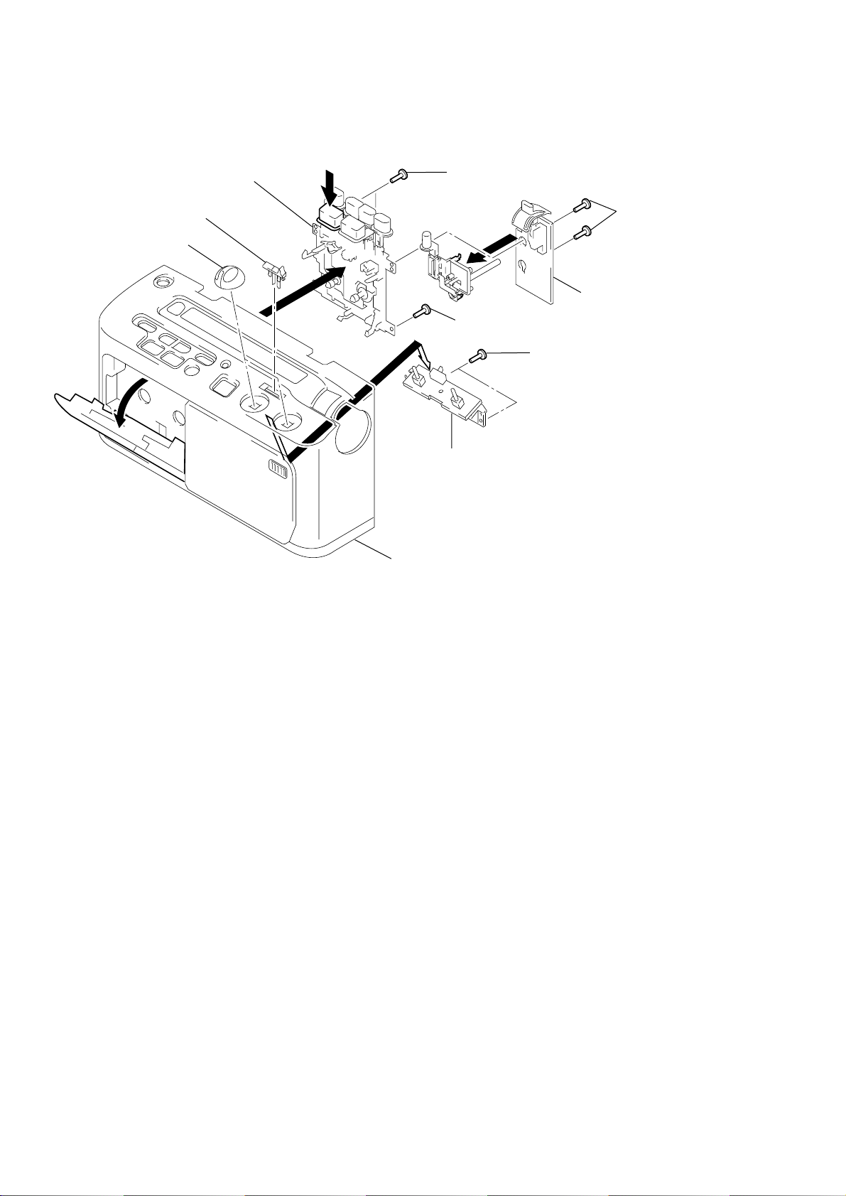
2-3. MAIN BOARD, TUN LED BOARD, TACT SW BOARD REMOVAL
5
2
4
4
3
7
6
1
Screws (+BV 3x10)
Cabinet (Front) assy
Main board
Chassis, TU
TACT SW board
TUN LED board
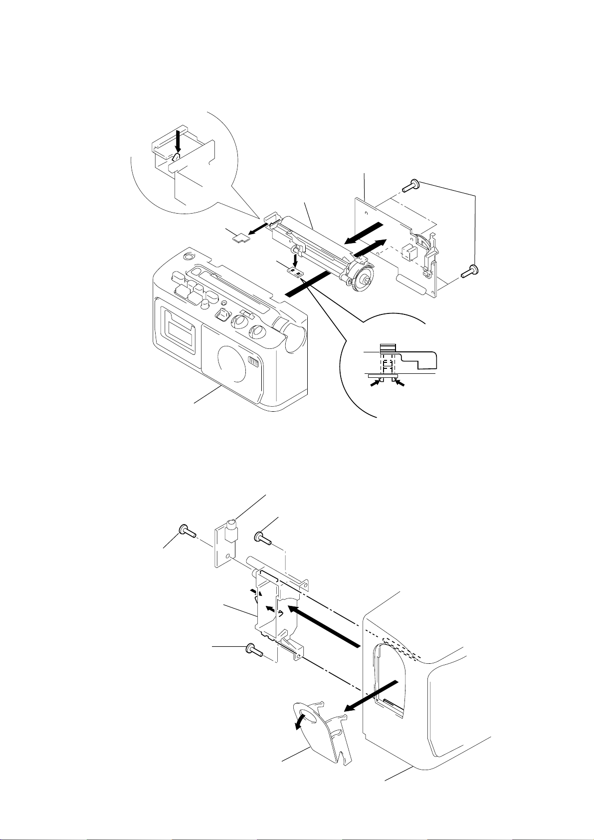
2-4. H/P JACK BOARD, DOOR EAR (PH), BOX EAR (PH) REMOVAL
H/P JACK board
4
Screw (+BV 3x10)
6
Screw
(+BV 3x10)
1
1
5
2
4
Screw (+BV 3x10)
Box, ear(PH)
3
DOOR, ear(PH)
Cabinet (Front) assy
– 5 –
2-5. MECHANISM DECK, DECK CONTROL BOARD, VOLUME BOARD REMOVAL
)
1
Mechanism deck
7
Knob (TONE SW)
7
Knob (VOL)
3
Screws (+BV 3x10)
6
5
Screws (+BV 3x10
2
4
3
Screw +BV (3x10)
9
Volume board
Cabinet (Front) assy
8
DECK CONTROL board
Screws (+BV 3x10)
– 6 –
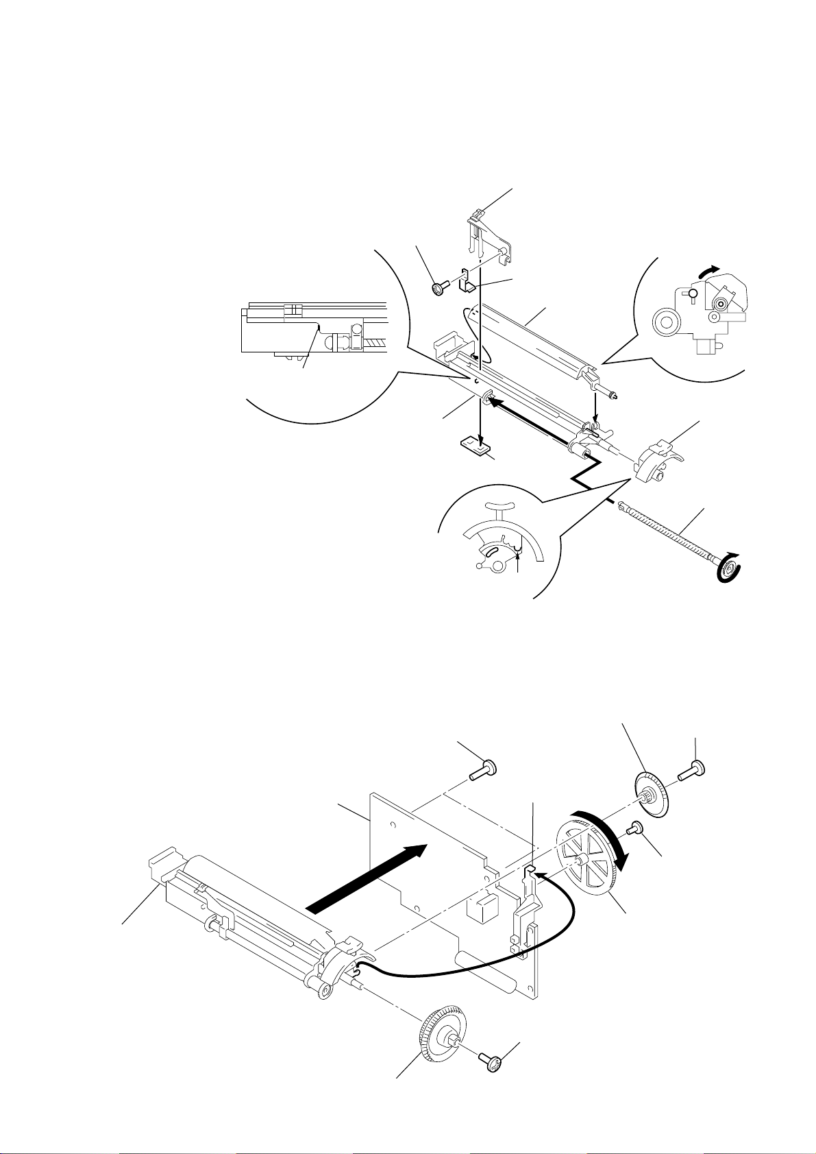
SECTION 3
d
DIAL POINTER SETTING
Note : Follow the instaooation procedure in the numerical order given.
1 Attach TU worm to tuner chassis.
2 Attach needle, tighten needle spring using a bolt, then attach TU
LED board.
3 Rotate TU worm until needle stops at the stopper shown in Fig. A.
Screw (+P 2.6x5)
2
Pointer
Fig. A
Stopper
Chassis, TU
4 Mount PLATE BLIND and position it as shown in Fig. B.
5 Attach the band knob. Make sure that the projected part of the
tuner chassis fits as shown in Fig. C (the arrow).
6 Tighten idler gear, combine projected part of band knob and the
band slider so that they interlock, then mount to main board.
7 Mount VR gear to main board, then turn in the direction of the
arrow until it stops.
8 Fasten the TU gear to the TU chassis with the screw.
Screws (+BV 3x10)
Retainer, Pointer
TUN LED board
Fig. C
4
Plate, blind
8
Gear, TU
Fig. B
5
Knob, ban
1
Worm, TU
3
Screw (+BV 3x10)
Chassis, TU
Main board
6
Gear, idler
– 7 –
Slieder, band
Screw (+BV 3x10)
Screw (+B 2.6x5)
7
Gear, VR
 Loading...