


CFD-Z125/Z135
MICROFILM
SERVICE MANUAL
Photo: CFD-Z135
CD
Section
Tape deck
Section
US Model
CFD-Z125/Z135
E Model
CFD-Z135
Model Name Using Similar Mechanism NEW
CD Mechanism Type KSM-213CDM/Z-NP
Optical Pick-up Name KSS-213C/Z-N
Model Name Using Similar Mechanism NEW
T ape Transport Mechanism Type MF-Z125
SPECIFICATIONS
AUDIO POWER SPECIFICATIONS
POWER OUTPUT AND TOTAL HARMONIC DISTORTION
With 3.2 Ω loads, both channel driven from 250 – 6,300 Hz; rated 2W per
channel-minimum RMS power, with no more than 10 % total harmonic
distortion in AC operation.
Other Specifications
CD player section
System Compact disc digital audio system
Laser diode properties Material: GaAlAs
Wave length:780 nm
Emission duration : Continuous
Laser output : Less than 44.6 µW
(This output is the value measured at a distance
of about 200 mm from the objective lens surface
on the optical pick-up block with 7 mm
aperture.)
Spindle speed 200 r/min (rpm) to 500 r/min (rpm) (CLV)
Number of channels 2
Frequency response 20 – 20,000 Hz + 3/-3 dB
Wow and flutter Below measurable limit
Radio section
Frequency range FM : 87.6 – 108 MHz
AM : 530 – 1,710 kHz
Aerials FM : Telescopic aerial
AM : Built-in ferrite bar aerial
Cassette-corder section
Recording system 4 -track 2 channel stereo
Fast winding time Approx. 110 s (sec.) with Sony cassette
C-60
Frequency response TYPE Ι (normal) : 80 – 10,000 Hz
General
Speakers Full range : 10 cm (4 in) dia., 3.2 Ω, cone
type (2)
Outputs Headphones jack (stereo minijack)
For 16 – 68 Ω impedance headphones
Power output (excluding US model)
2.3 W + 2.3 W (at 3.2 Ω, 10 % harmonic
distortion in DC operation)
Power requirements For CD radio cassette-corder :
120V AC, 60 Hz
9V DC, 6 size D (R20) batteries
For remote (CFD-Z135 only) :
3V DC, 2 size AA (R6) batteries
Power consumption AC 19W
— Continued on next page —
CD RADIO CASSETTE-CORDER
Battery life For CD radio cassette-corder:
FM recording
Sony R20P : approx. 7 h
Sony alkaline LR20 : approx. 14.5 h
Tape playbac k
Sony R20P : approx. 3.5 h
Sony alkaline LR20 : approx. 8 h
CD playback
Sony R20P : approx. 2 h
Sony alkaline LR20 : approx. 4.5 h
Dimensions Approx. 622 × 275 × 230 mm (w/h/d)
(24 1/2 × 10 7/8 × 9 1/8 inches) (incl. projecting
parts)
Mass Approx. 6.8 kg (15 lb.) (incl. batteries)
Supplied accessories AC power cord (1)
Remote controller (1) (CFD-Z135 only)
Design and specifications are subject to change without notice.
SAFETY CHECK-OUT
After correcting the original service problem, perform the
following safety checks before releasing the set to the customer:
Check the antenna terminals, metal trim, “metallized” knobs, screws,
and all other exposed metal parts for AC leaka ge. Check leakage as
described below.
LEAKAGE
The AC leakage fr om any exposed metal part to earth ground
and from all exposed metal parts to any exposed metal part having
a return to chassis, must not exceed 0.5 mA (500 microamperes).
Leakage current can be measured by any one of three methods.
1. A commercial leakage tester, such as the Simpson 229 or RCA
WT -540A. F ollow the manuf acturers’ instructions to use these
instruments.
2. A battery-operated AC milliammeter. The Data Precision 245
digital multimeter is suitable for this job.
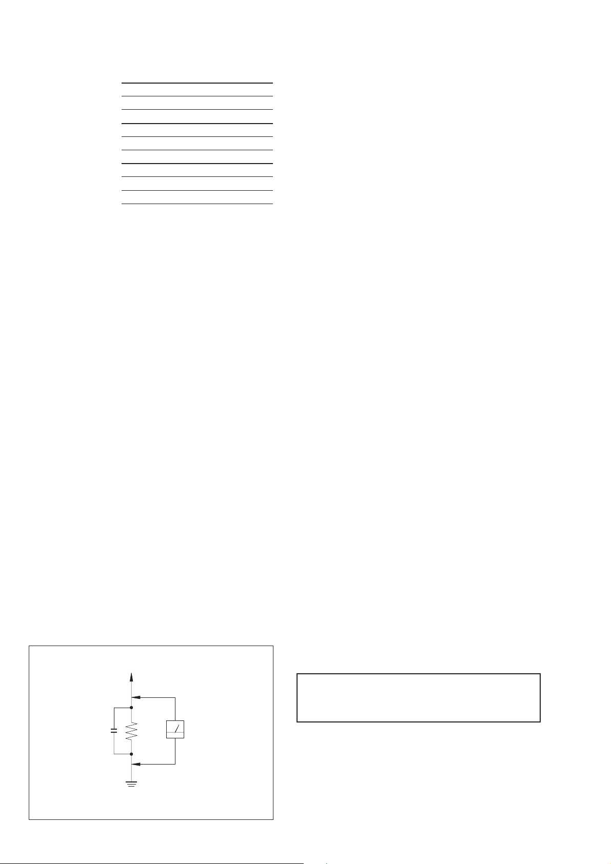
3. Measuring the voltage drop across a resistor by means of a
VOM or battery-operated A C voltmeter . The “limit” indication
is 0.75 V, so analog meters must have an accurate low-v oltage
scale. The Simpson 250 and Sanwa SH-63Trd are examples of
a passive VOM that is suitable. Nearly all battery operated
digital multimeters that have a 2V AC range are suitable. (See
Fig. A)
TABLE OF CONTENTS
1. SERVICE NOTES ···························································· 3
2. GENERAL ·········································································· 4
3. DISASSEMBLY
3-1. Rear Cabinet ······································································· 9
3-2. CD Block ·········································································· 10
3-3. Main Board, SP Terminal Board ······································ 10
3-4. CD Decoder Board, Lamp Board ····································· 11
3-5. Optical Pick-up Section (KSM-213CDM/Z-NP) ············· 11
3-6. Optical Pick-up (KSS-213C/Z-N) ···································· 12
3-7. Motor Board, Sled Motor (M702) ···································· 12
3-8. Front Board, Sensor Board ··············································· 13
3-9. Mechanism Deck (MF-Z125)···········································13
3-10. Belt, Capstan/Reel Motor (M601)····································14
3-11. Cassette Door ··································································· 14
4. DIAL POINTER SETTING·········································· 15
5. ADJUSTMENTS
5-1. Mechanical Adjustment ···················································· 16
5-2. Electrical Adjustment
Tape Deck Section ···························································· 16
Tuner Section···································································· 18
CD Section ······································································· 20
6. DIAGRAMS
6-1. Circuit Boards Location ··················································· 23
6-2. Block Diagram ································································· 24
6-3. Printed Wiring Board —CD Section — ··························· 29
6-4. Schematic Diagram — CD Section — ·····························32
6-5. Schematic Diagram — Main Section — ························· 35
6-6. Printed Wiring Board —Main Section — ························ 39
6-7. Printed Wiring Board —Front Section — ························ 43
6-8. Schematic Diagram —Front Section —···························45
6-9. IC Pin Function Description ·············································47
7. EXPLODED VIEWS
7-1. Back Cabinet Section ······················································· 49
7-2. Front Panel Section ·························································· 50
7-3. CD Block Section ····························································· 51
7-4. Optical Pick-up Section (KSM-213CDM/Z-NP) ············· 52
7-5. Mechanism Deck Section-1·············································· 53
7-6. Mechanism Deck Section-2·············································· 54
7-7. Speaker Section ································································ 55
8. ELECTRICAL PARTS LIST·······································56
T o Exposed Metal
Parts on Set
AC
0.15
µ
F
Fig. A. Using an AC voltmeter to check AC leakage.
1.5 k
Ω
Earth Ground
Voltmeter
(0.75 V)
CAUTION
Use of controls or adjustments or performance of procedures
other than those specified herein may result in hazardous radiation
exposure.
SAFETY-RELATED COMPONENT WARNING!!
COMPONENTS IDENTIFIED BY MARK ! OR DO TTED LINE WITH
MARK ! ON THE SCHEMATIC DIAGRAMS AND IN THE PARTS
LIST ARE CRITICAL TO SAFE OPERATION. REPLACE THESE
COMPONENTS WITH SONY PARTS WHOSE PART NUMBERS
APPEAR AS SHOWN IN THIS MANUAL OR IN SUPPLEMENTS
PUBLISHED BY SONY.
— 2 —
SECTION 1
mark 1
mark 2
CF1,4
SERVICE NOTES
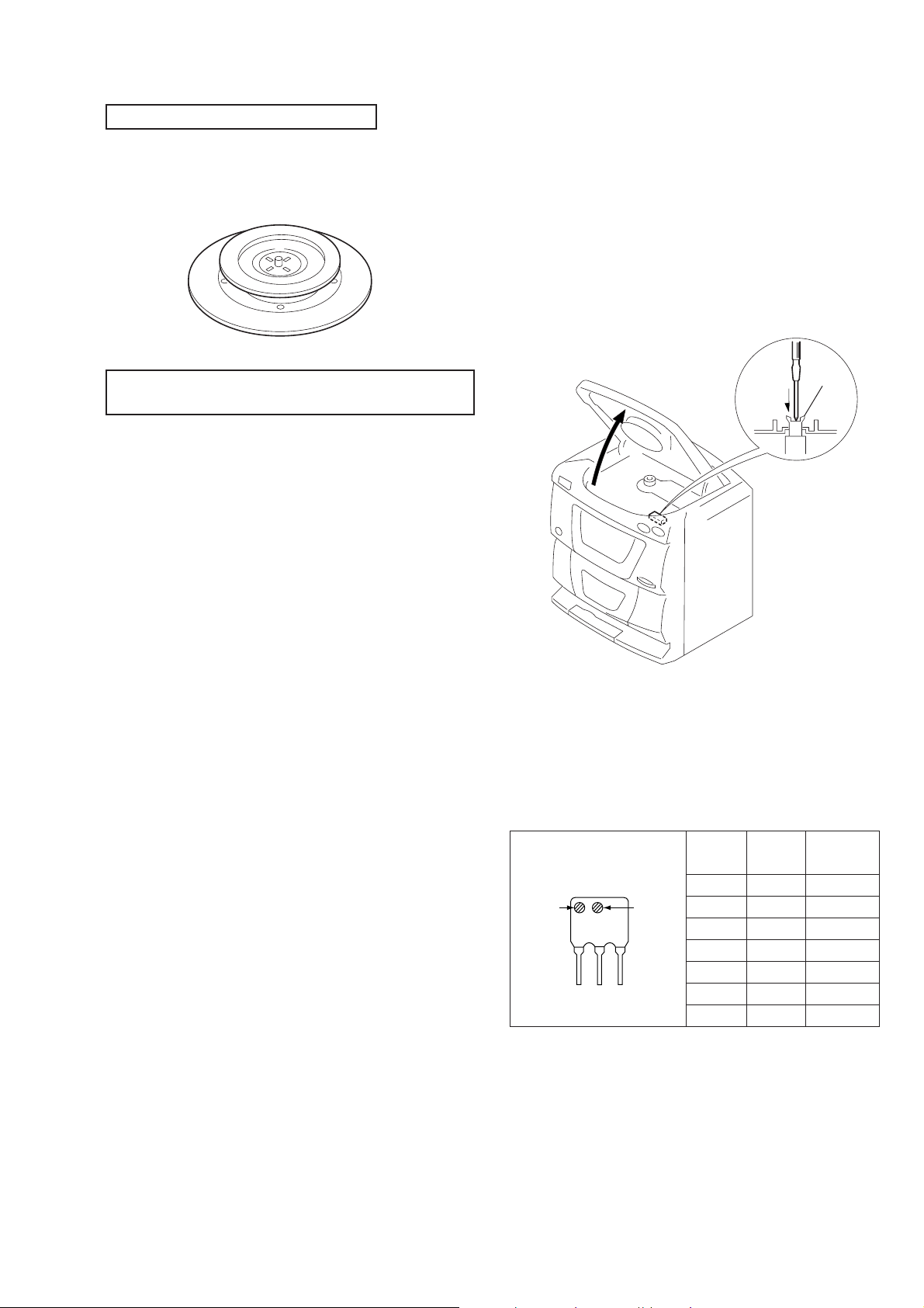
CHUCK PLATE JIG ON REPAIRING
On repairing CD section, playing a disc without the CD lid, use
Chuck Plate Jig.
• Code number of Chuck Plate Jig : X-4918-255-1
NOTES ON HANDLING THE OPTICAL PICK-UP
BLOCK OR BASE UNIT
The laser diode in the optical pick-up block may suffer electrostatic
breakdown because of the potential difference generated by the
charged electrostatic load, etc. on clothing and the human body.
During repair, pay attention to electrostatic breakdown and also use
the procedure in the printed matter which is included in the repair
parts.
The flexible board is easily damaged and should be handled with
care.
LASER DIODE AND FOCUS SEARCH OPERATION
CHECK
1. Turn POWER switch on with no disc inserted and make Function
switch to CD position.
2. Open the lid for CD.
3. Turn on S702 as following figure.
4. Press the fl button.
5. Confirm the laser diode emission while observing the objecting
lens. When there is no emission, Auto Power Control circuit or
optical pick-up is broken.
Objective lens moves up and down three times for the focus
search.
S702
NOTES ON LASER DIODE EMISSION CHECK
The laser beam on this model is concentrated so as to be focused on
the disc reflective surface by the objective lens in the optical pickup block. Therefore, when checking the laser diode emission,
observe from more than 30 cm away from the objective lens.
HOW TO CHANGE THE FM CERAMIC FILTERS
This model uses the two ceramic filters of CF1 and CF4.
Y ou m ust use the same type of color marked ceramic filters in order
to meet same specifications.
Therefore, the ceramic filter must change two pieces together since
it’s supply two pieces in one package as a spare parts.
Mark 1 Mark 2
red — 10.70MHz
blue — 10.67MHz
orange — 10.73MHz
black — 10.64MHz
white — 10.76MHz
white white 10.75MHz
yellow — 10.79MHz
Center
frequency
— 3 —

SECTION 2
GENERAL
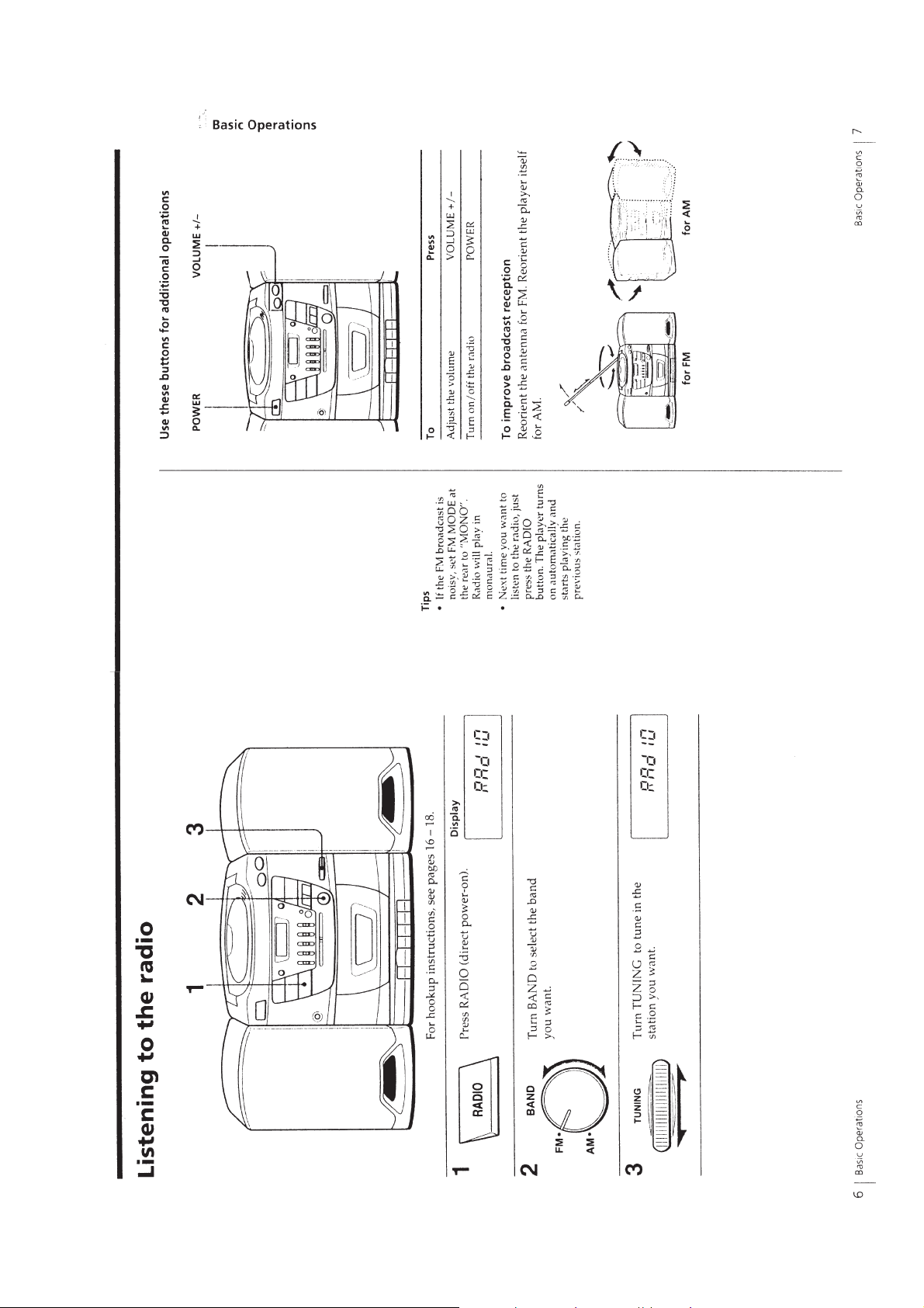
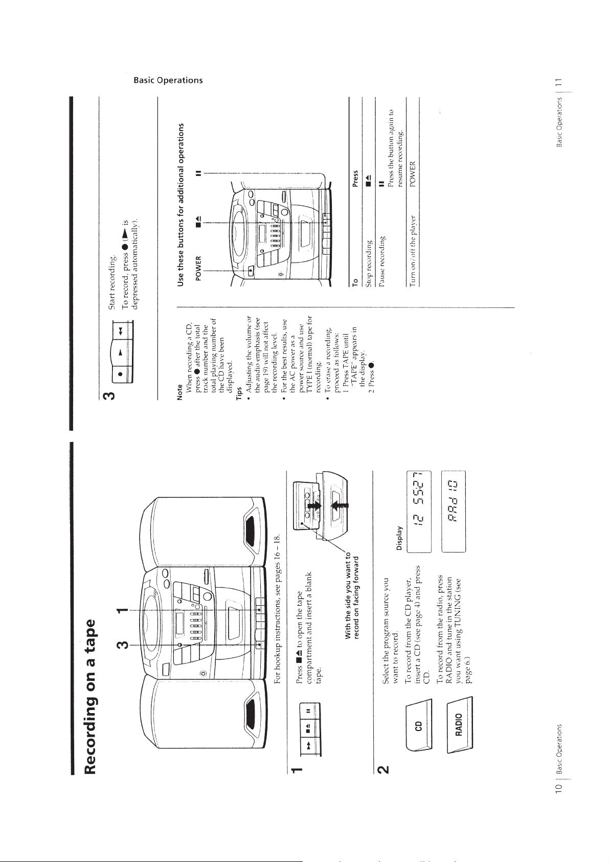
This section is extracted
from instruction manual.
— 4 —
— 5 —

— 6 —
— 7 —
— 8 —
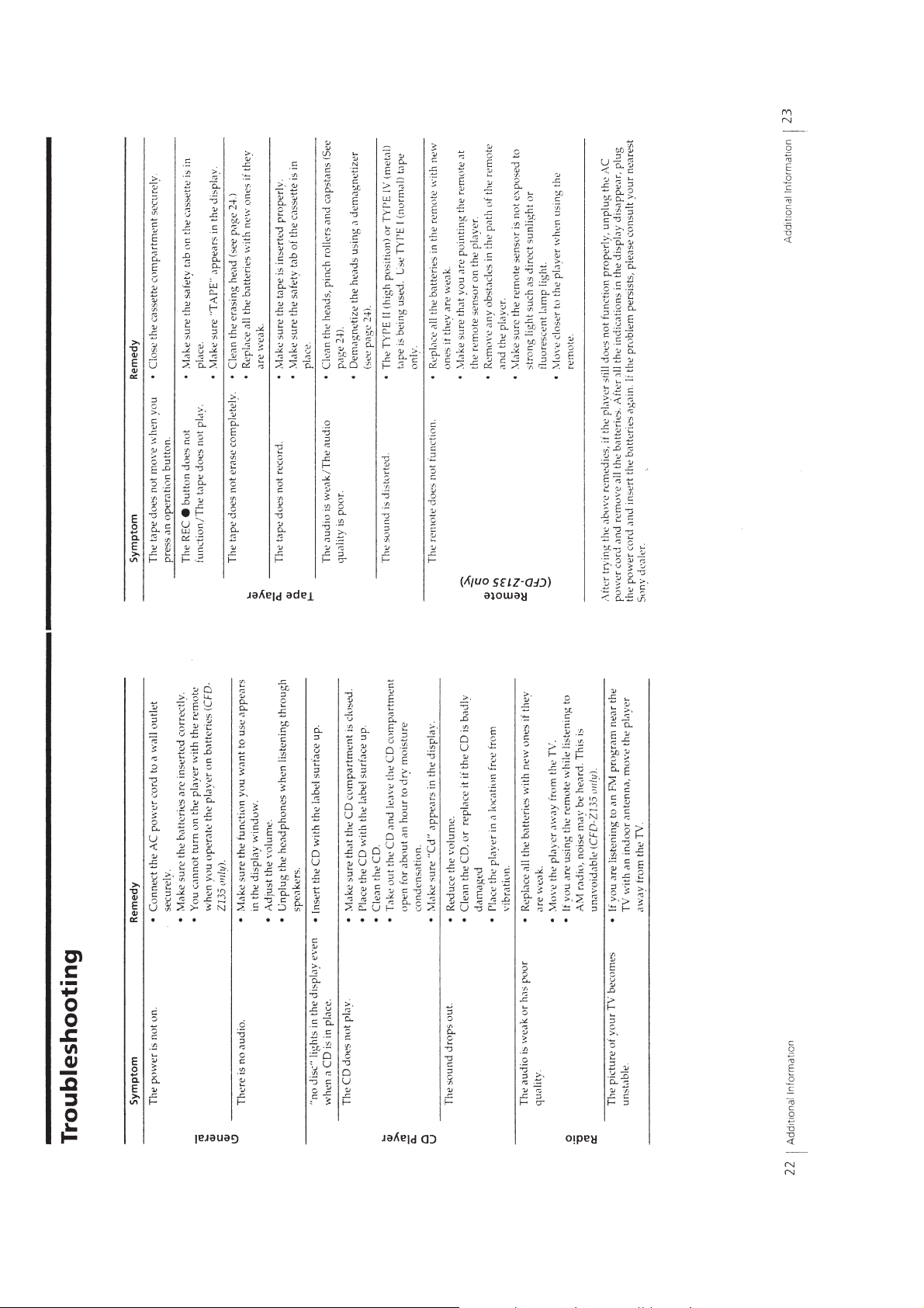
• This set can be disassembled in the order shown below.
d
SECTION 3
DISASSEMBLY
SET
REAR CABINET
(Page 9)
CASEETTE DOOR
(Page 14)
CD BLOCK
(Page 10)
MECHANISM DECK
(Page 13)
MAIN BOARD,
SP TERMINAL BOARD
(Page 10)
FRONT BOARD,
SENSOR BOARD
(Page 13)
BELT,
CAPSTAN/REEL MOTOR (M601)
(Page 14)
Note : Follow the disassembly procedure in the numerical order given.
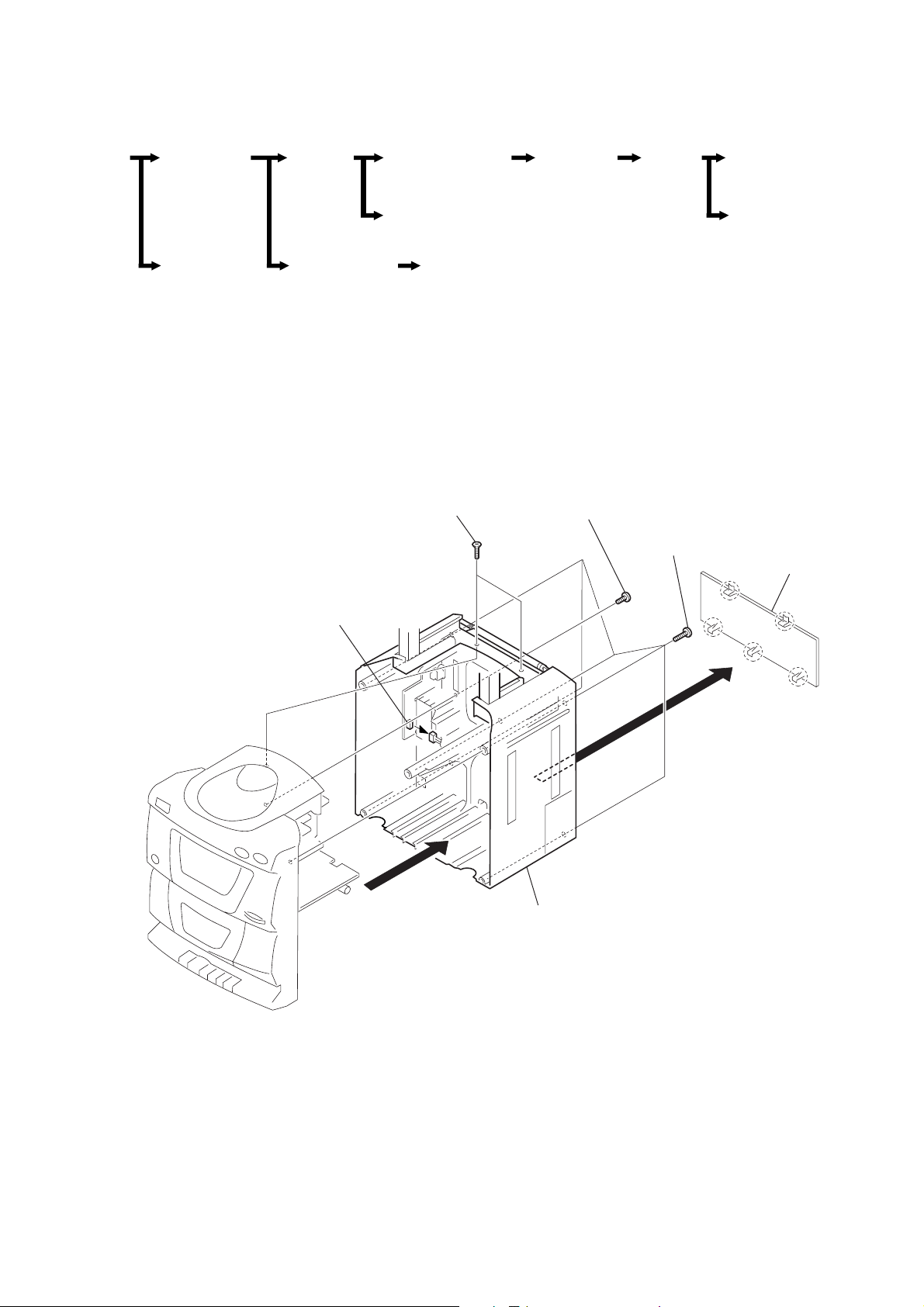
3-1. REAR CABINET
4
Screw 2pcs
(+KTP 3 ×12)
CD DECODER
BOARD,
LAMP BOARD
(Page 11)
3
Screw
(+BTP 3 ×12)
OPTICAL
PICK-UP
SECTION
(Page 11)
2
Screws 5pcs
(+BTP 3 ×16)
OPTICAL
PICK-UP
(Page 12)
MOTOR BOARD,
SLED BOARD (M702)
(Page 12)
1
Battery Case li
6
CN304
5
Rear Cabinet
— 9 —

d
3-2. CD BLOCK
4
CD Block
2
CN302
3
Screws 5pcs
(+BTP 3 ×12)
3-3. MAIN BOARD, SP TERMINAL BOARD
5
SP TERMINAL
Board
1
CN305
4
MAIN Boar
3
Screws 3pcs
(+BTP 3 ×12)
— 10 —
2
CN07
1
CN303
3-4. CD DECODER BOARD, LAMP BOARD
)
1
CN801
6
Board
7
Two claws
CD DECODER
8
CN706
4
Screws 2pcs
(+BTP 3 ×10)
Remove
solder
9
LAMP Board (Z135 only)
2
CN701
3
CN802
3
CN703
5
Lag
3-5. OPTICAL PICK-UP SECTION
(KSM-213CDM/Z-NP)
2
Optical Pick-up
Section
(KSM-213CDM/Z-NP
1
Screws 4pcs
(+PTPWH 2.6 ×8)
— 11 —
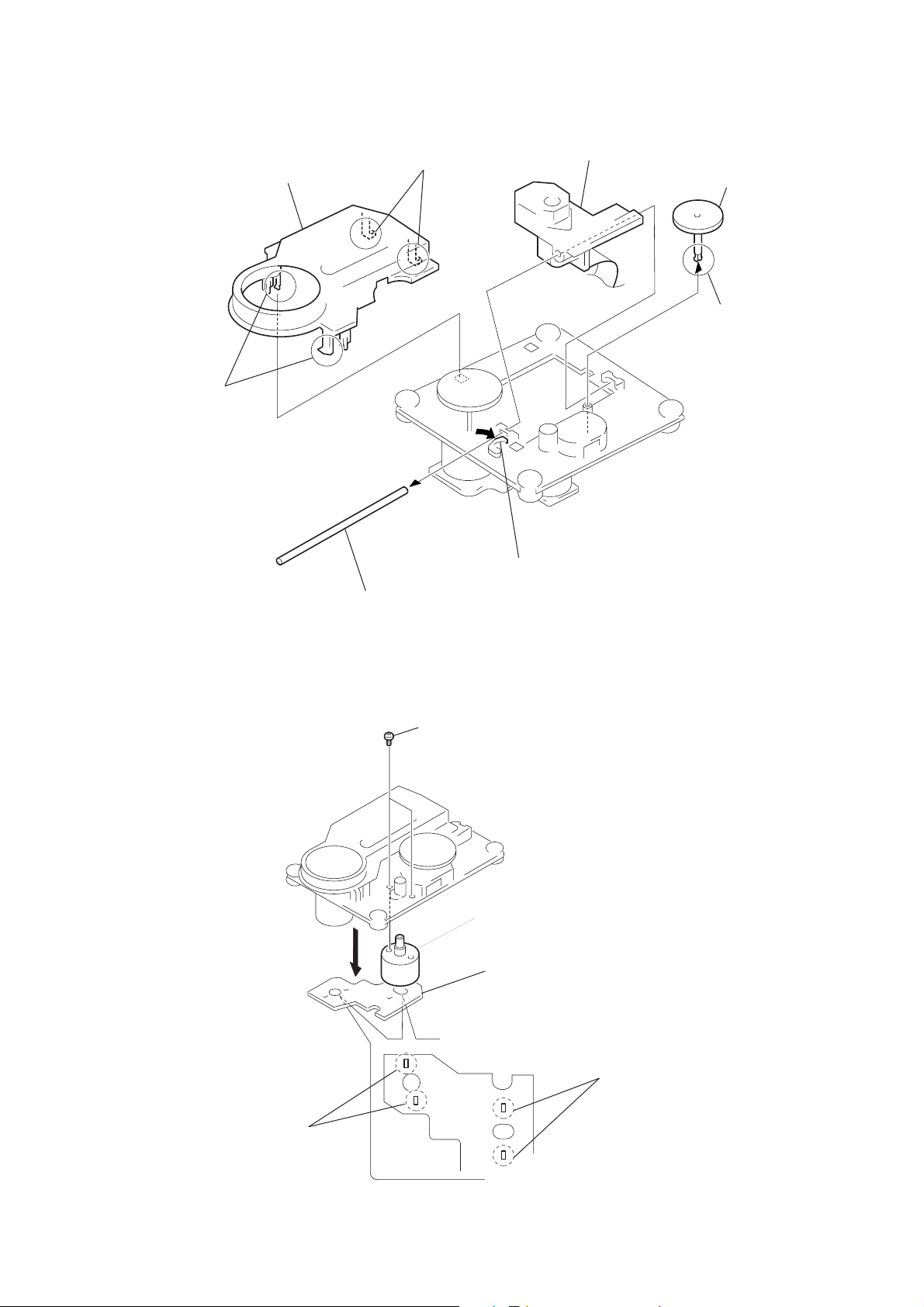
3-6. OPTICAL PICK-UP
s
r
(KSS-213C/Z-N)
1
Two claws
2
CD Pick-up Cover
1
Two claws
7
Optical Pick-up
(KSS-213C/Z-N)
4
3
A gea
Claw
6
Sled shaft
3-7. MOTOR BOARD, SLED MOTOR (M702)
3
Screws 2pcs
(+P 2 × 3)
4
5
Claw
Sled motor (M702)
2
MOTOR Board
1
Remove
two solders
— 12 —
1
Remove
two solder
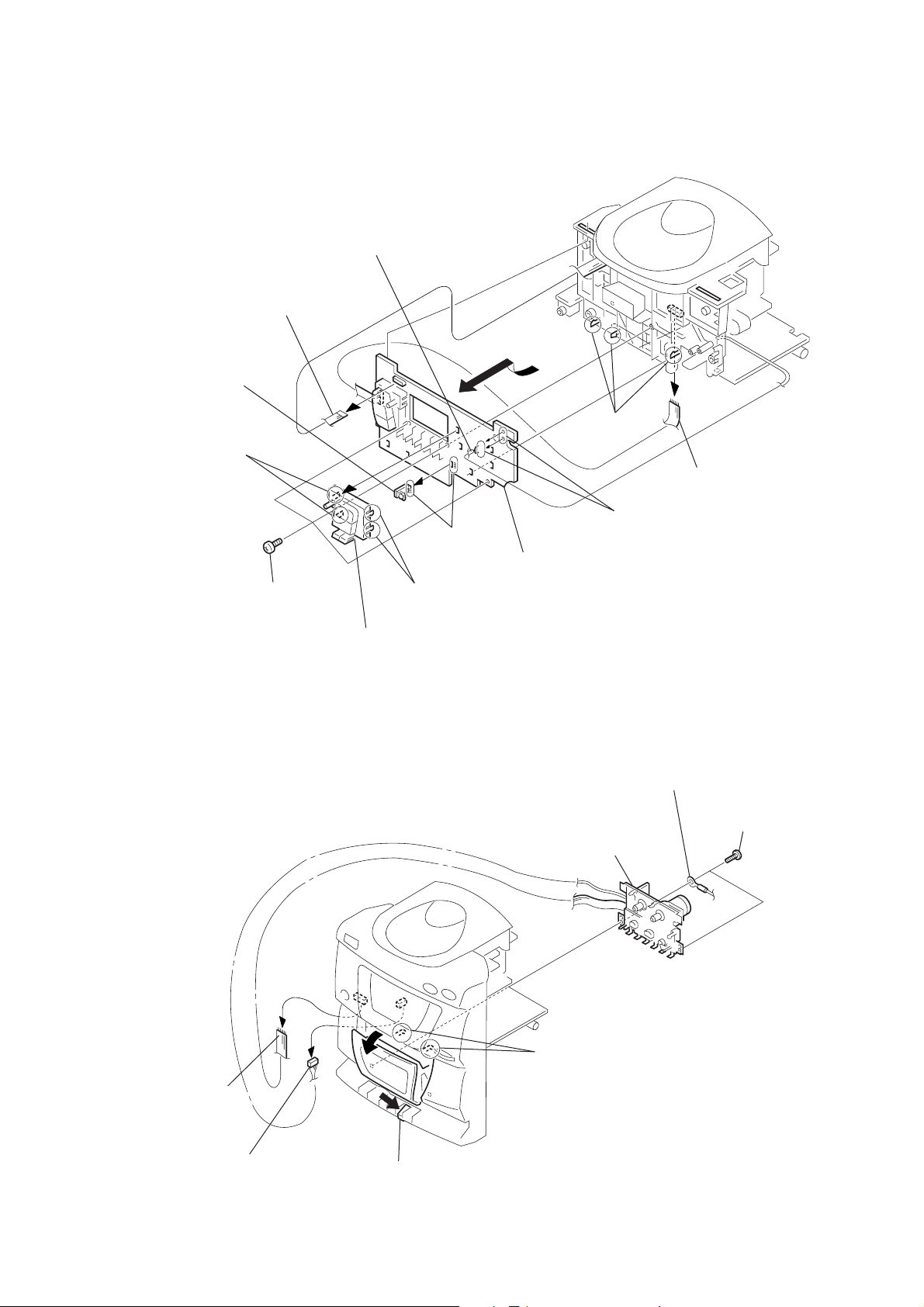
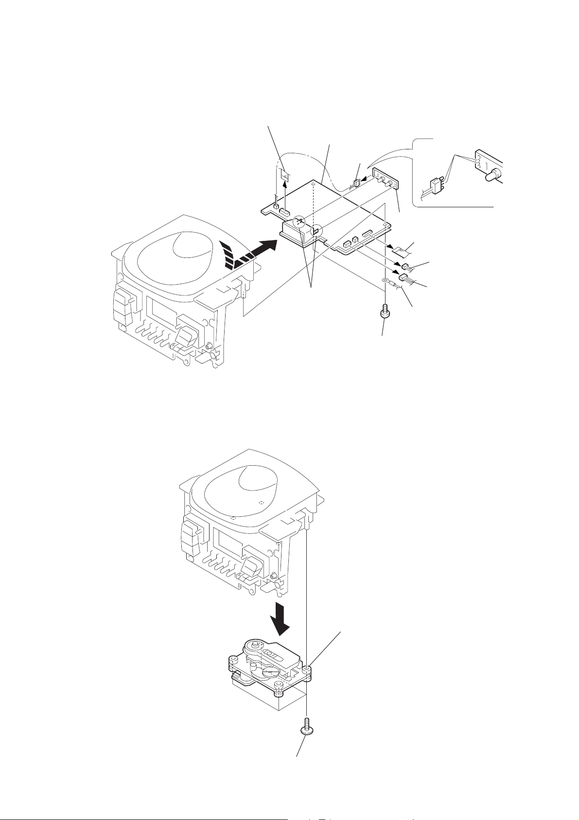
3-8. FRONT BOARD, SENSOR BOARD
)
8
Earth wire
1
CN003
!¡
SENSOR board
(Z135 only)
3
Two claws
5
Screws 3pcs
(+BTP 3 ×10)
3
0
Remove solder
Two claws
9
FRONT board
6
Three
claws
7
2
CN303
Remove solder
4
Function button
3-9. MECHANISM DECK (MF-Z125)
1
CN305
7
Mechanism deck
(MF-Z125)
6
Two claws
5
lag
4
Screws 2pcs
(+BTP 3 ×10
2
CN302
3
Press the eject ( p 6) button
— 13 —
 Loading...