

Sony CDX-R3300, CDX-R3300S Installation Guide
FM/AM
Compact Disc
Player
Installation/Connections
Instalación/Conexiones
安裝線路連接
3-261-846-21 (1)
2
A
B
CDX-R3300
CDX-R3300S
CDX-R3000
© 2004 Sony Corporation Printed in Korea
1
12
4675
× 4
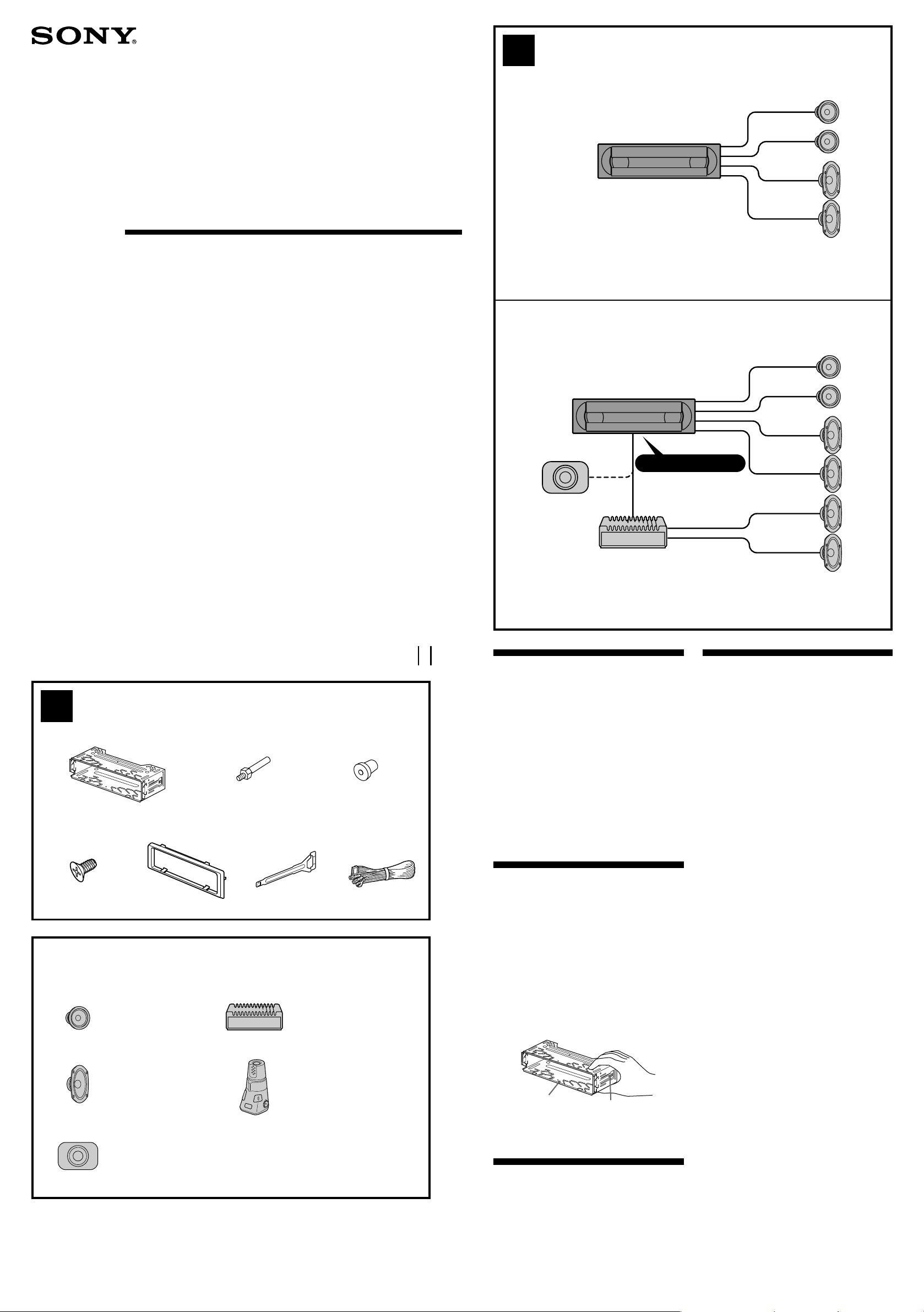
Equipment used in illustrations (not supplied)
Equipo utilizado en las ilustraciones (no suministrado)
插圖中的裝置(非附送)
Front speaker
Altavoz frontal
前揚聲器
Rear speaker
Altavoz posterior
後揚聲器
Active subwoofer
Subwoofer activo
有源超低音揚聲器
3
× 2
Power amplifier
Amplificador de potencia
功率放大器
Rotary commander RM-X4S
Mando rotativo RM-X4S
旋轉式控制器 RM-X4S
AUDIO OUT REAR
Cautions
•This unit is designed for negative earth 12 V DC
operation only.
•Do not get the leads under a screw, or caught in
moving parts (e.g. seat railing).
•Before making connections, turn the car ignition
off to avoid short circuits.
•Connect the yellow and red power input leads
only after all other leads have been connected.
•Run all earth leads to a common earth point.
•Be sure to insulate any loose unconnected leads
with electrical tape for safety.
Notes on the power supply lead (yellow)
•When connecting this unit in combination with
other stereo components, the connected car
circuit’s rating must be higher than the sum of
each component’s fuse.
•When no car circuits are rated high enough,
connect the unit directly to the battery.
Parts Iist (1)
•The numbers in the list are keyed to those in the
instructions.
•The bracket 1 and the protection collar 5 are
attached to the unit before shipping. Before
mounting the unit, use the release keys 6 to
remove the bracket 1 and the protection collar 5
from the unit. For details, see “Removing the
protection collar and the bracket (4)” on the
reverse side of the sheet.
•Keep the release keys 6 for future use as they
are also necessary if you remove the unit from
your car.
Caution
Handle the bracket 1 carefully to avoid injuring
your fingers.
1
Note
Before installing, make sure that the catches on both
sides of the bracket 1 are bent inwards 2 mm. If the
catches are straight or bent outwards, the unit
will not be installed securely and may spring out.
Catch
Connection example (2)
Notes (2-B)
• Be sure to connect the earth lead before connecting
the amplifier.
• If you connect an optional power amplifier and do not
use the built-in amplifier, the beep sound will be
deactivated.
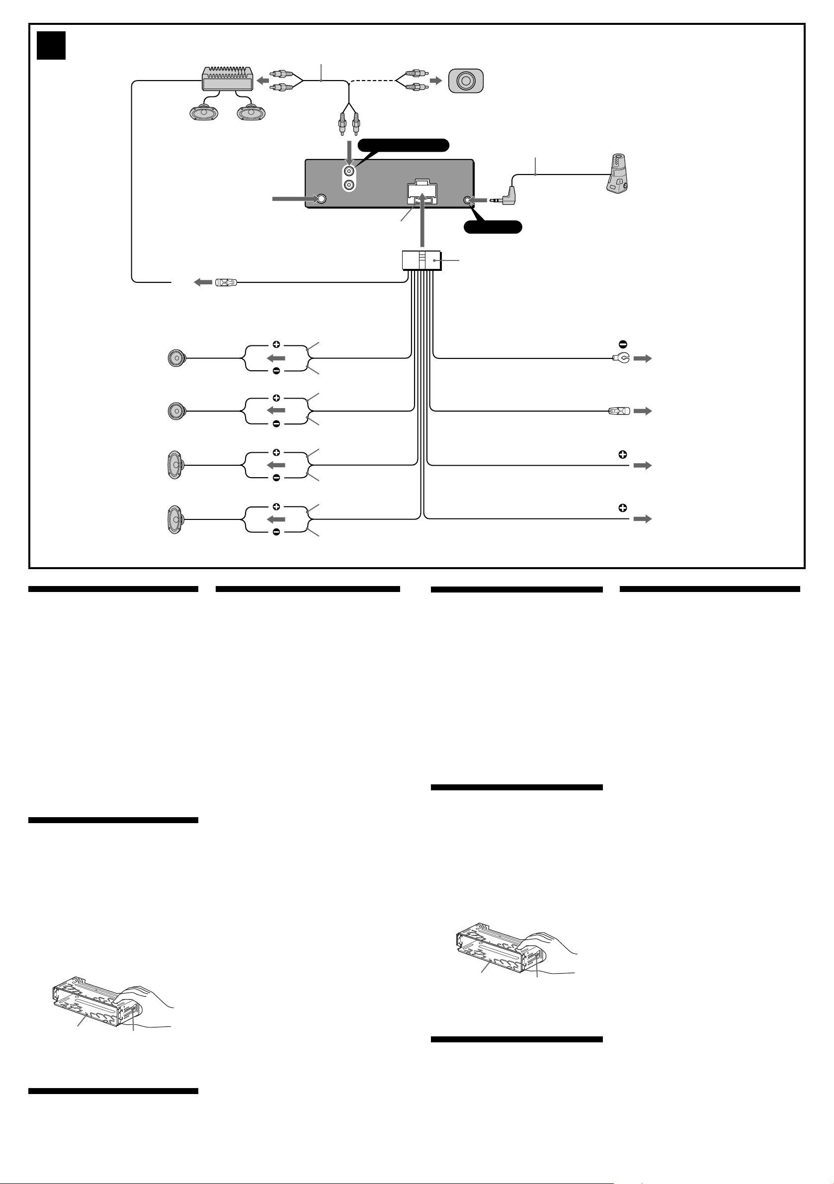
Connection diagram (3)
1 To a metal surface of the car
First connect the black earth lead, then connect the
yellow and red power input leads.
2 To the power aerial control lead or power
supply lead of aerial booster amplifier
Notes
• It is not necessary to connect this lead if there is no
power aerial or aerial booster, or with a manuallyoperated telescopic aerial.
• When your car has a built-in FM/AM aerial in the
rear/side glass, see “Notes on the control and
power supply leads.”
3 To AMP REMOTE IN of an optional power
amplifier
This connection is only for amplifiers. Connecting
any other system may damage the unit.
4 To the +12 V power terminal which is energized
in the accessory position of the ignition key
switch
Notes
•If there is no accessory position, connect to the +12
V power (battery) terminal which is energized at
all times.
Be sure to connect the black earth lead to a metal
surface of the car first.
• When your car has a built-in FM/AM aerial in the
rear/side glass, see “Notes on the control and
power supply leads.”
5 To the +12 V power terminal which is energized
at all times
Be sure to connect the black earth lead to a metal
surface of the car first.
Notes on the control and power supply leads
• The power aerial control lead (blue) supplies +12 V DC
when you turn on the tuner.
• When your car has built-in FM/AM aerial in the rear/
side glass, connect the power aerial control lead (blue)
or the accessory power input lead (red) to the power
terminal of the existing aerial booster. For details,
consult your dealer.
•A power aerial without relay box cannot be used with
this unit.
Memory hold connection
When the yellow power input lead is connected, power
will always be supplied to the memory circuit even when
the ignition key is turned off.
Notes on speaker connection
• Before connecting the speakers, turn the unit off.
• Use speakers with an impedance of 4 to 8 ohms, and
with adequate power handling capacities to avoid its
damage.
• Do not connect the speaker terminals to the car
chassis, or connect the terminals of the right speakers
with those of the left speaker.
• Do not connect the earth lead of this unit to the
negative (–) terminal of the speaker.
• Do not attempt to connect the speakers in parallel.
• Connect only passive speakers. Connecting active
speakers (with built-in amplifiers) to the speaker
terminals may damage the unit.
• To avoid a malfunction, do not use the built-in speaker
leads installed in your car if the unit shares a common
negative (–) lead for the right and left speakers.
•Do not connect the unit’s speaker leads to each other.
Note on connection
If speaker and amplifier are not connected correctly,
“FAILURE” appears in the display. In this case, make sure
the speaker and amplifier are connected correctly.
3
from car aerial
desde la antena del automóvil
來自汽車天線
1
*
AUDIO OUT REAR
L
L
R
R
BUS
AUDIO
AUDIO
OUT
IN
REAR
Fuse (10 A)
Fusible (10 A)
保險絲(10 A)
2
*
3
*
REMOTE IN
1
RCA pin cord (not supplied)
*
2
*
AUDIO OUT can be switched to REAR
or SUB.
For details, see the supplied operating
instructions.
3
Insert with the cord upwards
*
1
*
Cable con terminales RCA (no
suministrado)
2
AUDIO OUT (Salida de audio) puede
*
cambiarse a REAR (Posterior) o SUB
(Secundaria).
Para obtener información, consulte el
manual de instrucciones suministrado.
3
Insertar con el cable hacia arriba
*
1
*
RCA 針型插頭電線(非附送)
2
*
AUDIO OUT 可以轉換為 REAR 或 SUB。
詳情請參閱附帶的使用說明書。
3
*
電線向上插入
Left
Izquierdo
左
Right
Derecho
右
Left
Izquierdo
左
Right
Derecho
右
3
Blue/white striped
Con rayas azules y blancas
AMP REM
Max. supply current 0.3 A
Corriente máx. de alimentación de 0,3 A
最大源電流 0.3 A
藍色白條紋
White
Blanco
白色
White/black striped
Con rayas blancas y negras
白黑條紋
Grey
Gris
灰色
Grey/black striped
Con rayas grises y negras
灰黑條紋
Green
Verde
綠色
Green/black striped
Con rayas verdes y negras
綠黑條紋
Purple
Morado
紫色
Purple/black striped
Con rayas violetas y negras
紫黑條紋
7
Black
Negro
黑色
Blue
Azul
藍色
Red
Rojo
紅色
Yellow
Amarillo
黃色
ANT REM
Corriente máx. de alimentación de 0,1 A
Max. supply current 0.1 A
最大源電流 0.1 A
1
2
4
5
Precauciones
• Esta unidad ha sido diseñada para alimentarse sólo
con cc de 12 V de masa negativa.
•No coloque los cables debajo de ningún tornillo, ni
los aprisione con partes móviles (p.ej. los raíles del
asiento).
• Antes de realizar las conexiones, desactive el
encendido del automóvil para evitar cortocircuitos.
• Conecte los cables de entrada de alimentación
amarillo y rojo solamente después de haber
conectado los demás.
• Conecte todos los conductores de puesta a
masa a un punto común.
• Por razones de seguridad, asegúrese de aislar con
cinta aislante los cables sueltos que no estén
conectados.
Notas sobre el cable de suministro de
alimentación (amarillo)
• Cuando conecte esta unidad en combinación con
otros componentes estéreo, la capacidad nominal
del circuito conectado del automóvil debe ser
superior a la suma del fusible de cada componente.
• Si no hay circuitos del automóvil con capacidad
nominal suficientemente alta, conecte la unidad
directamente a la batería.
Lista de componentes (1)
• Los números de la lista corresponden a los de las
instrucciones.
• La unidad se comercializa con el soporte 1 y el
marco de protección 5 instalados. Antes de
montarla, utilice las llaves de liberación 6 para
extraer el soporte 1 y el marco de protección 5.
Para obtener más información, consulte
“Extracción del marco de protección y del soporte
(4)” en el reverso de la hoja.
• Conserve las llaves de liberación 6 para
utilizarlas en el futuro, ya que también las
necesitará si retira la unidad del automóvil.
Precaución
Tenga mucho cuidado al manipular el soporte 1
para evitar posibles lesiones en los dedos.
Nota
1
Antes de instalar la unidad, compruebe que los
enganches de ambos lados del soporte 1 están doblados
hacia adentro 2 mm. Si no lo están o están doblados hacia
afuera, la unidad no se instalará correctamente y puede
saltar.
Enganche
Ejemplo de conexiones (2)
Notas (2-B)
• Asegúrese de conectar primero el cable de toma a tierra
antes de realizar la conexión al amplificador.
• Si conecta un amplificador de potencia opcional y no
utiliza el incorporado, los pitidos se desactivarán.
Diagrama de conexión (3)
1
A una superficie metálica del automóvil
Conecte primero el cable de
los cables amarillo y rojo de entrada de alimentación.
2
Al cable de control de la antena motorizada o al cable
de fuente de alimentación del amplificador de antena
Notas
• Si no se dispone de antena motorizada ni de amplificador
de antena, o se utiliza una antena telescópica accionada
manualmente, no será necesario conectar este cable.
• Si el automóvil incorpora una antena de FM/AM en el
cristal trasero o lateral, consulte “Notas sobre los cables
de control y de fuente de alimentación”.
3
Para conectar a AMP REMOTE IN del amplificador de
potencia opcional
Esta conexión es sólo para amplificadores. La conexión de
cualquier otro sistema puede dañar la unidad.
4
Al terminal de alimentación de +12 V que recibe
energía en la posición de accesorio del interruptor de
la llave de encendido
Notas
• Si no hay posición de accesorio, conéctelo al terminal de
alimentación (batería) de +12 V que recibe energía sin
interrupción.
Asegúrese de conectar primero el cable de toma a tierra
negro a una superficie metálica del automóvil.
• Si el automóvil incorpora una antena de FM/AM en el
cristal trasero o lateral, consulte “Notas sobre los cables
de control y de fuente de alimentación”.
5
Al terminal de alimentación de +12 V que recibe
energía sin interrupción
Asegúrese de conectar primero el cable de toma a tierra
negro a una superficie metálica del automóvil.
Notas sobre los cables de control y de fuente de
alimentación
• El cable de control de la antena motorizada (azul)
suministrará cc de + 12 V cuando conecte la alimentación del
sintonizador.
• Si el automóvil dispone de una antena de FM/AM
incorporada en el cristal trasero o lateral, conecte el cable de
control de antena motorizada (azul) o el cable de entrada de
alimentación auxiliar (rojo) al terminal de alimentación del
amplificador de antena existente. Para obtener más
información, consulte a su proveedor.
• Con esta unidad no es posible utilizar una antena motorizada
sin caja de relé.
Conexión para protección de la memoria
Si conecta el conductor de entrada amarillo, el circuito de la
memoria recibirá siempre alimentación, aunque ponga la llave
de encendido en la posición OFF.
Notas sobre la conexión de los altavoces
• Antes de conectar los altavoces, desconecte la alimentación
de la unidad.
• Utilice altavoces con una impedancia de 4 a 8 Ω con la
capacidad de potencia adecuada para evitar que se dañen.
• No conecte los terminales de altavoz al chasis del automóvil,
ni conecte los terminales del altavoz derecho con los del
izquierdo.
• No conecte el cable de toma a tierra de esta unidad al
terminal negativo (–) del altavoz.
• No intente conectar los altavoces en paralelo.
• Conecte solamente altavoces pasivos. Si conecta altavoces
activos (con amplificadores incorporados) a los terminales de
altavoz, puede dañar la unidad.
• Para evitar fallos de funcionamiento, no utilice los cables de
altavoz incorporados instalados en el automóvil si su unidad
comparte un cable negativo común (–) para los altavoces
derecho e izquierdo.
•No conecte los cables de altavoz de la unidad entre sí.
Nota sobre la conexión
Si el altavoz y el amplificador no están conectados
correctamente, aparecerá “FAILURE” en la pantalla. Si es así,
compruebe la conexión de ambos dispositivos.
toma a tierra
negro, y después
注意
• 本機只能使用負極接地 12 V 直流電源。
• 不要使導線夾在螺栓下,或繞掛在移動部件上
(如:座椅扶手上)。
• 連接線路之前,請關閉汽車點火裝置以免引起短
路。
• 黃色和紅色電源輸入導線必須在所有其它導線都
連接完畢以後才連接。
• 將所有地線都連接到同一接地點。
• 為了安全,請確認把沒有連接的導線用電器膠帶
包紮進行絕緣。
電源導線須知(黃色)
• 將本機與其它立體聲裝置組合使用時,所連接的
汽車電路容量必須大於每個裝置保險絲容量的總
和。
• 當汽車電路容量不夠大時,請將本機直接與電池
相連接。
零件一覽表(1)
• 圖示數字與說明書中的數字是一致的。
• 托架 1 和保護環 5 在出廠之前已經裝在本裝
置上。在安裝本裝置之前,請先使用開鎖鑰匙 6
將托架 1 和保護環 5 從本裝置上拆下。詳細
說明,請參見本頁反面“拆下保護環和托架
(4)”。
• 如果要將本裝置從汽車上拆下,也要使用開鎖鑰
匙,因此請保存好開鎖鑰匙 6 以備今後使用。
注意
拿取托架 1 時,請特別注意別傷到手指。
1
註
安裝之前,必須將托架
果拌鉤筆直或向外彎曲,則本裝置將無法牢固安裝,並可
能彈出。
拌鉤
1
兩側的拌鉤向內彎曲 2 mm。如
線路連接圖例(2)
註
(2-B)
•
務必在接放大器之前連接地線。
•
如果您連接了選購的功率放大器而不使用內置放大
器,將無提示聲功能。
線路連接圖(3)
1 連接至汽車的金屬表面
首先連接黑色接地導線,然後再連接黃色和紅色電源輸
入導線。
2 連接至電動天線控制導線或天線升壓放大器的電源導線
註
•
如無電動天線或天線升壓器,或有手動套管式天線,
便不須連接此導線。
•
您汽車的後側玻璃窗中如果有內置 FM/AM 天線,即
請參看“控制線和電源線須知”。
3 連接至選購的功率放大器的 AMP REMOTE IN(放大器遙控
輸入)
本連接僅用於放大器。連接任何其它系統可能會損壞本
機。
4 連接至在點火鑰匙開關的附件位置上通電的 +12 V 電源
端子
註
•
若沒有附件位置,則請連接至始終通電的 +12 V 電源
(電池)端子。
必須首先將黑色接地導線連接至汽車的金屬表面。
•
您汽車的後側玻璃窗中如果有內置 FM/AM 天線,即
請參看“控制線和電源線須知”。
5 連接至始終通電的 +12 V 電源端子
必須首先將黑色接地導線連接至汽車的金屬表面。
控制線和電源線須知
•
接通調諧器電源時,電動天線的控制導線(藍色)便能提
供 +12 V 直流電。
•
若您的汽車後側玻璃窗上有內置 FM/AM 天線,須將電動
天線控制導線(藍色)或輔助電源輸入導線(紅色)連接
到現有天線升壓器的電源端子上。詳細內容請向銷售商諮
詢。
•
本機不能使用不具備繼電器盒的電動天線。
保持記憶的線路連接法
當連接好黃色電源輸入導線時,即使汽車發動機點火鑰匙關
閉,電源仍將對記憶電路供電。
連接揚聲器時的注意事項
•
連接揚聲器電線以前,請先關閉本機電源。
•
使用阻抗為 4-8Ω 且具有足夠功率處理容量的揚聲器,以
免損壞揚聲器。
•
不要將揚聲器端子連接到車身上,或將右揚聲器端子與左
揚聲器端子相連接。
•
切勿將本機的接地導線連接至揚聲器的負(-)接線端。
•
揚聲器不可並聯連接。
•
請僅連接無源揚聲器。若將有源揚聲器(帶內置放大器)
連接到揚聲器端子上會損壞本機。
•
若本裝置使用左、右揚聲器的共用負極( - ) 導線,為了避
免故障,切勿使用已安裝在汽車內的內置揚聲器導線。
•
請勿將本裝置揚聲器導線相互連接。
有關連接注意事項
如果未正確連接揚聲器和放大器,則顯示幕上會出現
“FAILURE”。此時,請正確連接揚聲器和放大器。
 Loading...