

SONY CDX-GT57UPW, CDX-GT62UMI, CDX-GT570UE, CDX-GT570UI, CDX-GT570UP SERVICE MANUAL
...
CDX-GT57UPW/GT62UMI/GT570UE/GT570UI/
GT570UP/GT574UI/GT620UI/GT626UI
SERVICE MANUAL
Ver. 1.1 2012.08
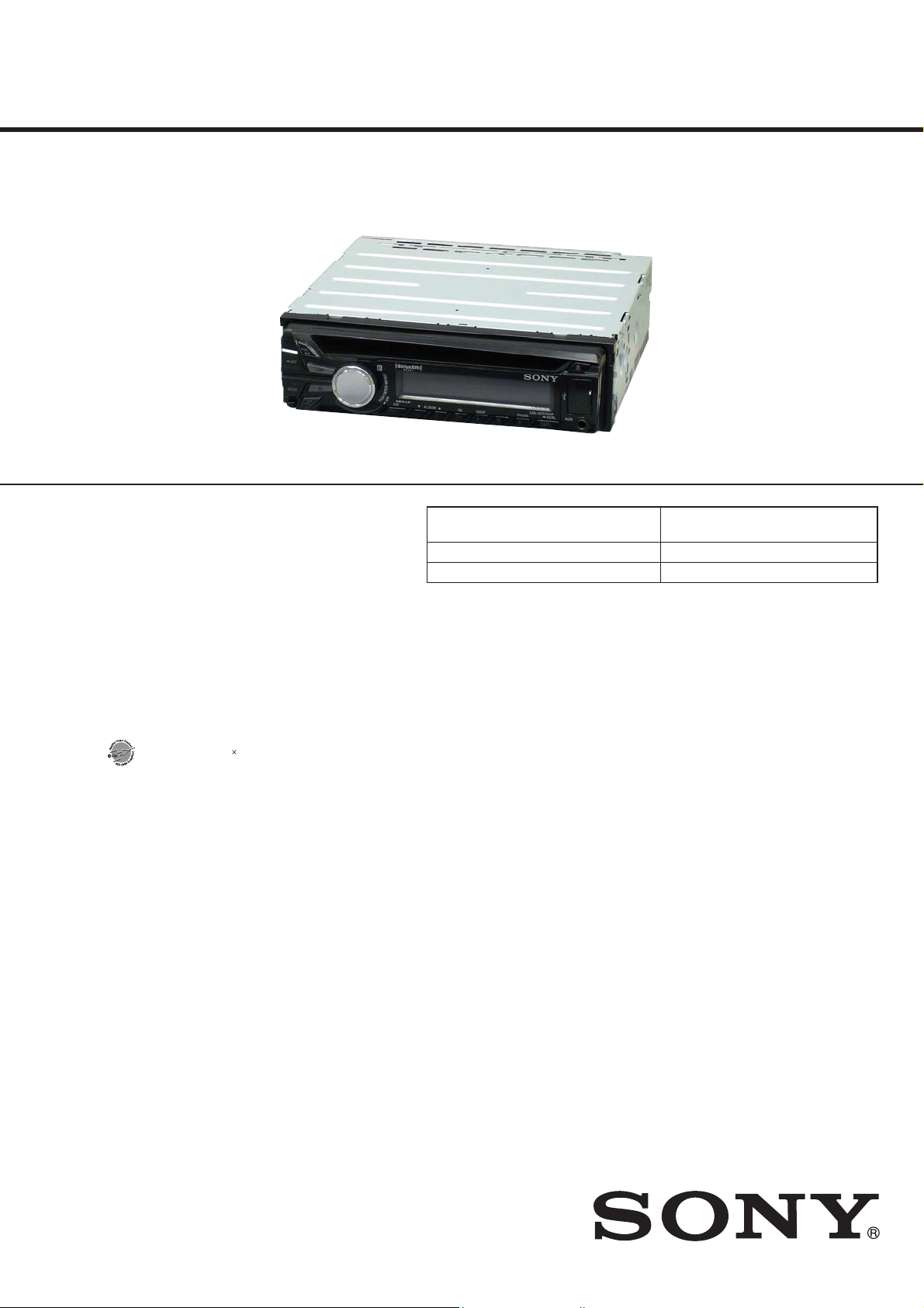
Photo: CDX-GT570UP
• The tuner and CD sections have no adjustments.
(CDX-GT570UP only)
FOR UNITED STATES CUSTOMERS. NOT
APPLICABLE IN CANADA, INCLUDING
IN THE PROVINCE OF QUEBEC.
POUR LES CONSOMMATEURS AUX
ÉTATS-UNIS. NON APPLICABLE AU
CANADA, Y COMPRIS LA PROVINCE DE
QUÉBEC.
(CDX-GT57UPW/GT570UP only)
AUDIO POWER SPECIFICATIONS
CEA2006 Standard
Power Output: 17 Watts RMS 4 at
4 Ohms < 1% THD+N
SN Ratio: 80 dBA
(reference: 1 Watt into 4 Ohms)
Tuner section
(
CDX-GT57UPW/GT570UP)
FM
Tuning range: 87.5 – 107.9 MHz
Antenna (aerial) terminal:
External antenna (aerial) connector
Intermediate frequency: 25 kHz
Usable sensitivity: 8 dBf
Selectivity: 75 dB at 400 kHz
Signal-to-noise ratio: 80 dB (stereo)
Separation: 50 dB at 1 kHz
Frequency response: 20 – 15,000 Hz
AM
Tuning range: 530 – 1,710 kHz
Antenna (aerial) terminal:
External antenna (aerial) connector
Intermediate frequency:
9,115 kHz or 9,125 kHz/5 kHz
Sensitivity: 26 μV
Tuner section
(CDX-GT570UI/GT574UI)
FM
Tuning range: 87.5 – 108.0 MHz
Antenna (aerial) terminal:
External antenna (aerial) connector
Intermediate frequency: 25 kHz
Usable sensitivity: 8 dBf
Selectivity: 75 dB at 400 kHz
Signal-to-noise ratio: 80 dB (stere o)
Separation: 50 dB at 1 kHz
Frequency response: 20 – 15,000 Hz
MW/LW
Tuning range:
MW: 531 – 1,602 kHz
LW: 153 – 279 kHz
Antenna (aerial) terminal:
External antenna (aerial) connector
Intermediate frequency:
9,124.5 kHz or 9,115.5 kHz/4.5 kHz
Sensitivity: MW: 26 μV, LW: 45 μV
Tuner section
(CDX-GT570UE)
FM
Tuning range:
FM1/FM2: 87.5 – 108.0 MHz
(at 50 kHz step)
FM3: 65 – 74 MHz
(at 30 kHz step)
Antenna (aerial) terminal:
External antenna (aerial) connector
Intermediate frequency: 25 kHz
Usable sensitivity: 8 dBf
Selectivity: 75 dB at 400 kHz
Signal-to-noise ratio: 80 dB (stere o)
Separation: 50 dB at 1 kHz
Frequency response: 20 – 15,000 Hz
MW/LW
Tuning range:
MW: 531 – 1,602 kHz
LW: 153 – 279 kHz
Antenna (aerial) terminal:
External antenna (aerial) connector
Intermediate frequency:
9,124.5 kHz or 9,115.5 kHz/4.5 kHz
Sensitivity: MW: 26 μV, LW: 45 μV
Tuner section
(CDX-GT62UMI/GT620UI:E,
Mexican/GT626UI)
FM
Tuning range:
87.5 – 108.0 MHz (at 50 kHz step)
87.5 – 108.0 MHz (at 100 kHz step)
87.5 – 107.9 MHz (at 200 kHz step)
FM tuning step:
50 kHz/100 kHz/200 kHz switchable
Antenna (aerial) terminal:
External antenna (aerial) connector
Intermediate frequency: 25 kHz
Usable sensitivity: 8 dBf
Selectivity: 75 dB at 400 kHz
Signal-to-noise ratio: 80 dB (stereo)
Separation: 50 dB at 1 kHz
Frequency response: 20 – 15,000 Hz
Model Name Using Similar Mechanism
Mechanism Type MG-101CA-188
Optical Pick-up Name DAX-25A
SPECIFICATIONS
AM
Tuning range:
531 – 1,602 kHz (at 9 kHz step)
530 – 1,710 kHz (at 10 kHz step)
ep:
AM tuning st
9 kHz/10 kHz switchable
Antenna (aerial) terminal:
External antenna (aerial) connector
Intermediate frequency:
9,124.5 kHz or 9,115.5 kHz/4.5 kHz
(at 9 kHz step)
9,115 kHz or 9,125 kHz/5 kHz
(at 10 kHz step)
Sensitivity: 26 μV
Tuner section
(CDX-GT620UI/
Saudi Arabia model)
FM
Tuning range:
87.5 – 108.0 MHz
Antenna (aerial) terminal:
External antenna (aerial) connector
Intermediate frequency: 25 kHz
Usable sensitivity: 8 dBf
Selectivity: 75 dB at 400 kHz
Signal-to-noise ratio: 80 dB (stereo)
Separation: 50 dB at 1 kHz
response: 20 – 15,000 Hz
Frequency
MW
Tuning range:
531 – 1,602 kHz
Antenna (aerial) terminal:
External antenna (aerial) connector
Intermediate frequency:
9,124.5 kHz or 9,115.5 kHz/4.5 kHz
Sensitivity: 26 μV
US Model
CDX-GT57UPW/GT570UP
Canadian Model
CDX-GT570UP
AEP Model
UK Model
CDX-GT570UI/GT574UI
E Model
CDX-GT620UI
Russian Model
CDX-GT570UE/GT570UI/GT574UI
Indian Model
CDX-GT62UMI/GT626UI
CDX-GT560UE/GT560UI/GT564UI/
GT565UP/GT610UG/GT616UG
SW
Tuning range:
SW1: 2,940 – 7,735 kHz
SW2: 9,500 – 18,135 kHz
(except for 10,140 – 11,575 kHz)
Antenna (aerial) terminal:
External antenna (aerial) connector
Intermediate frequency:
9,124.5 kHz or 9,115.5 kHz/4.5 kHz
Sensitivity: 26 μV
CD Player section
Signal-to-noise ratio: 120 dB
Frequency response: 10 – 20,000 Hz
ow and utter: Below measurable limit
W
USB Player section
Interface: USB (Full-speed)
Maximum current: 1 A
Power amplier section
Speaker outputs
Output:
Speaker impedance: 4 – 8 ohms
Maximum power output: 52 W 4 (at 4 ohms)
General
Outputs:
Audio outputs terminal (front, rear/sub
switchable) (CDX-GT62UMI/GT570UP/GT620UI
/GT626UI)
Audio outputs terminal (rear/sub switchable)
(CDX-GT57UPW/GT570UE/GT570UI/GT574UI)
Power antenna (aerial)/Power amplier control
terminal (REM OUT)
Inputs:
SiriusXM input terminal (CDX-GT570UP only)
Remote controller input terminal
Antenna (aerial) input terminal
put jack (stereo mini jack)
AUX in
USB port
Power requirements: 12 V DC car battery
(negative groun d (earth))
Dimensions: Approx. 178 50 177 mm
1
/8 2 7 in) (w/h/d)
(7
Mounting dimensions: Approx. 182 53 160 mm
1
/4 21/8 65/16 in) (w/h/d)
(7
Mass: Approx. 1.2 kg (2 lb 11 oz)
Supplied accessories:
Remote commander: RM-X211
(CDX-GT57UPW/GT62UMI/GT570UP/GT620UI
/GT626UI only)
Parts for installation and connections (1 set)
Design and specications are subject to change
without notice.
US, Canadian, E, Mexican and Indian models
FM/AM COMPACT DISC PLAYER
AEP, Russian and UK models
FM/MW/LW COMPACT DISC PLAYER
Saudi Arabia model
FM/MW/SW COMPACT DISC PLAYER
9-893-496-02
2012H33-1
2012.08
©
Sony Corporation
Published by Sony Techno Create Corporation
CDX-GT57UPW/GT62UMI/GT570UE/GT570UI/GT570UP/GT574UI/GT620UI/GT626UI
Ver. 1.1
TABLE OF CONTENTS
1. SERVICING NOTES ............................................. 3
2. GENERAL .................................................................. 6
3. DISASSEMBLY
ZAPPIN and Quick-BrowZer are
trademarks of Sony Corporation.
Windows Media is either a registered
trademark or trademark of Microso
Corporation in the United States and/or
other countries.
is product contains technology subject
to certain intellectual property rights of
Microso. Use or distribution of this
technology outside of this product is
prohibited without the appropriate
license(s) from Microso.
iPhone, iPod, iPod classic, iPod nano, and
iPod touch are trademarks of Apple Inc.,
registered in the U.S. and other countries.
MPEG Layer-3 audio coding technology
and patents licensed from Fraunhofer IIS
and omson.
Pandora, the Pandora logo, and the
Pandora trade dress are trademarks or
registered trademarks of Pandora Media,
Inc., used with permission.
Android is a trademark of Google Inc. Use
of this trademark is subject to Google
Permissions.
• US and Canadian models:
CAUTION
The use of optical instruments with this
product will increase eye hazard.
CAUTION
Use of controls or adjustments or performance of procedures
other than those specifi ed herein may result in hazardous radia-
tion exposure.
NOTES ON CHIP COMPONENT REPLACEMENT
• Never reuse a disconnected chip component.
• Notice that the minus side of a tantalum capacitor may be damaged by heat.
3-1. Disassembly Flow ........................................................... 18
3-2. Mini Fuse (Blade Type) (10A/32V) (FU1), Cover ......... 18
3-3. Sub Panel Block .............................................................. 19
3-4. CD Mechanism Deck (MG-101CA-188) ....................... 19
3-5. MAIN Board ................................................................... 20
3-6. SERVO Board ................................................................. 20
3-7. Chassis (T) Sub Assy ...................................................... 21
3-8. Roller Arm Assy .............................................................. 21
3-9. Chassis (OP) Assy ........................................................... 22
3-10. Chucking Arm Sub Assy ................................................. 22
3-11. Sled Motor Assy .............................................................. 23
3-12. Optical Pick-up Section .................................................. 24
3-13. Optical Pick-up ............................................................... 24
4. DIAGRAMS
4-1. Block Diagram - SERVO Section - ................................ 25
4-2. Block Diagram - MAIN Section - ................................... 26
4-3. Block Diagram
- PANEL, POWER SUPPLY Section - ........................... 27
4-4. Schematic Diagram - MAIN Section (1/5) - ................... 29
4-5. Schematic Diagram - MAIN Section (2/5) - ................... 30
4-6. Schematic Diagram - MAIN Section (3/5) - ................... 31
4-7. Schematic Diagram - MAIN Section (4/5) - ................... 32
4-8. Schematic Diagram - MAIN Section (5/5) - ................... 33
4-9. Printed Wiring Board - MAIN Section (1/2)
(Except Saudi Arabia model) - ........................................ 34
4-10. Printed Wiring Board - MAIN Section (2/2)
(Except Saudi Arabia model) - ....................................... 35
4-11. Printed Wiring Board - KEY Board -.............................. 36
4-12. Schematic Diagram - KEY Board - ................................ 37
5. EXPLODED VIEWS
5-1. Main Section ................................................................... 46
5-2. Front Panel Section ......................................................... 47
5-3. CD Mechanism Deck Section (MG-101CA-188) .......... 48
6. ELECTRICAL PARTS LIST .............................. 49
Accessories are given in the last of the electrical parts list.
Note: Refer to SUPPLEMENT-1 for printed wiring board of the
MAIN board (CDX-GT620UI: Saudi Arabia model).
FLEXIBLE CIRCUIT BOARD REPAIRING
• Keep the temperature of soldering iron around 270 °C during
repairing.
• Do not touch the soldering iron on the same conductor of the
circuit board (within 3 times).
• Be careful not to apply force on the conductor when soldering
or unsoldering.
SAFETY-RELATED COMPONENT WARNING!
COMPONENTS IDENTIFIED BY MARK 0 OR DOTTED LINE
WITH MARK 0 ON THE SCHEMATIC DIAGRAMS AND IN
THE PARTS LIST ARE CRITICAL TO SAFE OPERATION.
REPLACE THESE COMPONENTS WITH SONY PARTS
WHOSE PART NUMBERS APPEAR AS SHOWN IN THIS
MANUAL OR IN SUPPLEMENTS PUBLISHED BY SONY.
2
ATTENTION AU COMPOSANT AYANT RAPPORT
À LA SÉCURITÉ!
LES COMPOSANTS IDENTIFIÉS PAR UNE MARQUE 0 SUR
LES DIAGRAMMES SCHÉMATIQUES ET LA LISTE DES
PIÈCES SONT CRITIQUES POUR LA SÉCURITÉ DE FONCTIONNEMENT. NE REMPLACER CES COMPOSANTS QUE
PAR DES PIÈCES SONY DONT LES NUMÉROS SONT DONNÉS DANS CE MANUEL OU DANS LES SUPPLÉMENTS
PUBLIÉS PAR SONY.
CDX-GT57UPW/GT62UMI/GT570UE/GT570UI/GT570UP/GT574UI/GT620UI/GT626UI
Ver. 1.1
SECTION 1
SERVICING NOTES
NOTES ON HANDLING THE OPTICAL PICK-UP
BLOCK OR BASE UNIT
The laser diode in the optical pick-up block may suffer electrostatic break-down because of the potential difference generated by
the charged electrostatic load, etc. on clothing and the human body .
During repair, pay attention to electrostatic break-down and also
use the procedure in the printed matter which is included in the
repair parts.
The fl exible board is easily damaged and should be handled with
care.
NOTES ON LASER DIODE EMISSION CHECK
Never look into the laser diode emission from right above when
checking it for adjustment. It is feared that you will lose your sight.
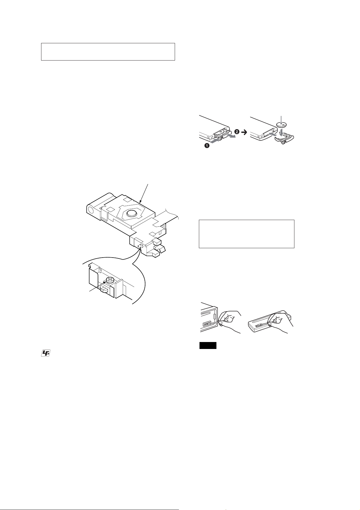
REPLACING THE LITHIUM BATTERY OF
THE REMOTE COMMANDER
(CDX-GT57UPW/GT62UMI/GT570UP/
GT620UI/GT626UI only)
When the batt
ery becomes weak, the range
of the remote commander becomes shorter.
Replace the battery with a new CR2025
lithium battery. Use of any other battery
may present a risk of re or explosion.
+ side up
If the optical pick-up block is defective, please replace the whole
optical pick-up block.
Never turn the semi-fi xed resistor located at the side of optical
pick-up block.
optical pick-up
semi-fixed resistor
UNLEADED SOLDER
Boards requiring use of unleaded solder are printed with the leadfree mark (LF) indicating the solder contains no lead.
(Caution: Some printed circuit boards may not come printed with
the lead free mark due to their particular size)
: LEAD FREE MARK
Unleaded solder has the following characteristics.
• Unleaded solder melts at a temperature about 40 °C higher
than ordinary solder.
Ordinary soldering irons can be used but the iron tip has to be
applied to the solder joint for a slightly longer time.
Soldering irons using a temperature regulator should be set to
about 350 °C.
Caution: The printed pattern (copper foil) may peel away if
the heated tip is applied for too long, so be careful!
• Strong viscosity
Unleaded solder is more viscous (sticky, less prone to fl ow)
than ordinary solder so use caution not to let solder bridges
occur such as on IC pins, etc.
• Usable with ordinary solder
It is best to use only unleaded solder but unleaded solder may
also be added to ordinary solder.
Notes on the lithium battery
t Keep the lithium battery out of the reach of
children. Should the battery be swallowed,
immediately consult a doctor.
t Wipe the battery with a dry cloth to assure a
good contact.
t Be sure to observe the correct polarity when
installing the battery.
t Do not hold the battery with metallic tweez
otherwise a short-circuit may occur.
ers,
WARNING
Battery may explode if mistreated.
Do not recharge, disassemble, or dispose
of in re.
CLEANING THE CONNECTORS
e unit may not function properly if the connectors
between the unit and the front panel are not clean. In order
to prevent this, detach the front panel and clean the
connectors with a cotton swab. Do not apply too much force.
Otherwise, the connectors may be damaged.
Notes
t For safety, turn o the ignition before cleaning the connectors,
and remove the key from the ignition switch.
t Never touch the connectors directly with your ngers or with
any metal device.
3
CDX-GT57UPW/GT62UMI/GT570UE/GT570UI/GT570UP/GT574UI/GT620UI/GT626UI
Ver. 1.1
NOTE THE MAIN BOARD OR SYSTEM CONTROLLER
(IC501) REPLACING
When the MAIN board or system controller (IC501) is replaced,
the destination setting is necessary.
1. Destination Setting
Set destination according to the procedure below.
1-1. Setting the Destination Code
1. In the state of source off (the clock is displayed), enter the test
mode by pressing the buttons in order of the [SHUF 4] t [5]
t [PAUSE 6] (press only the [PAUSE 6] button for two seconds).
2. In the state in which the system controller version is displayed
on the liquid crystal display (refer to following fi gure), enter
the destination setting mode by pressing the buttons in order
of the [
> M SEEK+] t [SEEK– m .] t [PUSH EN-
TER/MENU].
(Displayed characters/values in the following fi gure are ex-
ample)
System controller version
SHUF
3. Input the alphanumeric character of 12 digits of “F XXXXXX”
displayed on the liquid crystal display, and execute the destination setting.
Note: Refer to following “1-3. Entering the Destination Code” for opera-
tion method.
4. The resetting operation is executed by pressing the [ OFF
SOURCE] button for 1 second after the setting ends, and the
unit returns to the normal condition.
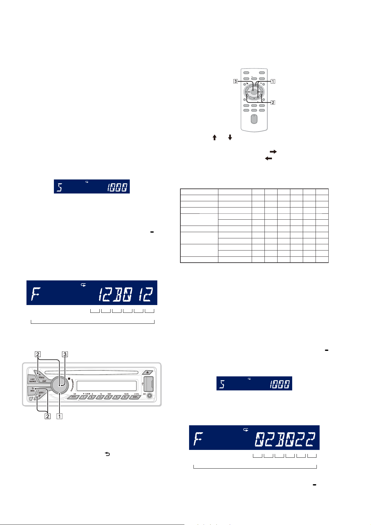
1-2. Display in Destination Setting Mode
(Displayed characters/values in the following fi gure are example)
Destination code
SHUF
• Method of operation by remote commander
(CDX-GT57UPW/GT62UMI/GT570UP/GT620UI/GT626UI
only)
Note: The model to which the remote commander is not attached can
also be operated by using the remote commander.
OFF
ATT
MENU
SOURCE
SOUND
MODE
+
ENTER
–
DSPL/
PTY
SCRL
+
VOL
–
1. Press the [ ] or [ ] button, and select the alphanumeric character of “0 to F”.
2. The digit advances by pressing the [ ] button.
The digit returns by pressing the [
] button.
3. The setting is completed by pressing the [ENTER] button, and
the initialization operation is done.
1-4. Destination Code
Model Destination OP5 OP4 OP3 OP2 OP1 OP0
CDX-GT57UPW US 0 2 B 0 2 2
CDX-GT62UMI Indian 4 0 B 8 8 0
CDX-GT570UE Russian C 0 B 0 5 7
CDX-GT570UI
AEP, UK 4 0 B 0 4 1
Russian C 0 B 0 4 1
CDX-GT570UP US, Canadian 1 2 B 0 1 2
CDX-GT574UI
CDX-GT620UI
AEP, UK 4 0 B 0 3 1
Russian C 0 B 0 3 1
E, Mexican 4 0 B 8 6 0
Saudi Arabia 4 0 B 8 6 4
CDX-GT626UI Indian 4 0 B 8 7 0
2. Confi rmation After Destination Setting
Execute the following operation after completing the destination
setting, and confi rm a correct destination was set.
OP5OP4OP3OP2OP1 OP0
12 digit
1-3. Entering the Destination Code
• Method of operation by main unit
1. Rotate the control dial, and select the alphanumeric character
of “0 to F”.
2. The digit advances by pressing the [PUSH ENTER/MENU] or
[> M SEEK+] button.
The digit returns by pressing the [ MODE] or [SEEK– m
.] button.
3. The setting is completed by pressing the [PUSH ENTER/
MENU] button, and the initialization operation is done.
Destination setting checking method:
1. In the state of source off (the clock is displayed on the liquid
crystal display), enter the test mode by pressing the buttons in
order of the [SHUF 4] t [5] t [PAUSE 6] (press only the
[PAUSE 6] button for two seconds).
2. In the state in which the system controller version is displayed
on the liquid crystal display (refer to following fi gure), enter
the destination setting value display mode by pressing the [
SCRL DSPL] button.
(Displayed characters/values in the following fi gure are example)
System controller version
SHUF
3. Confi rm the alphanumeric character of 12 digits in liquid crys-
tal display is an value correctly input.
(Displayed characters/values in the following fi gure are example)
Destination code
SHUF
OP5OP4OP3OP2OP1 OP0
12 digit
4. The resetting operation is executed by pressing the [ OFF
SOURCE] button for 1 second after the confi rming ends, and
the unit returns to the normal condition.
4
CDX-GT57UPW/GT62UMI/GT570UE/GT570UI/GT570UP/GT574UI/GT620UI/GT626UI
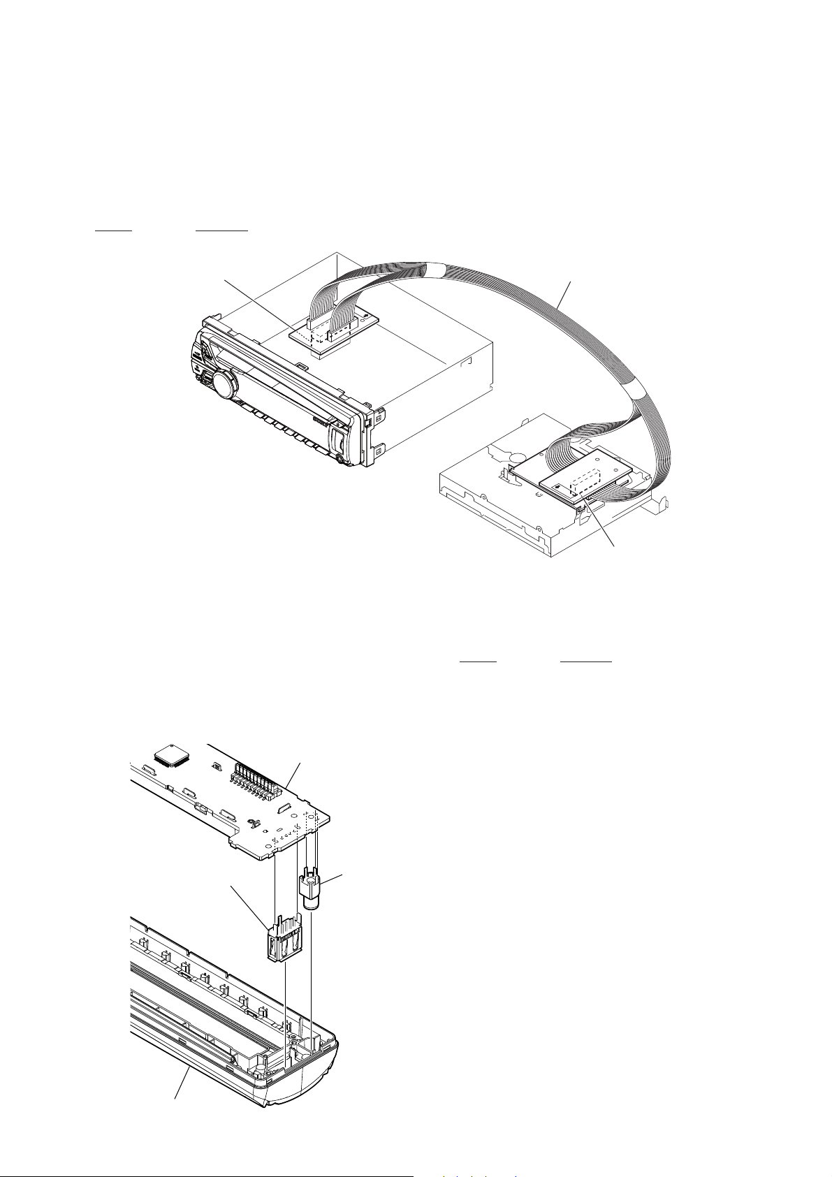
EXTENSION CABLE AND SERVICE POSITION
When repairing or servicing this set, connect the jig cable (extension cable (CD mecha)) as shown below.
• Connect the MAIN board (CN700) and the SERVO board
(CN401) with the jig cable.
Jig cable:
Part No. Description
A-1818-424-A EXTENSION CABLE (CD MECHA)
MAIN board
(CN700)
extension cable (CD mecha)
NOTE FOR REPLACEMENT OF THE USB CONNECTOR (CN903) AND AUX JACK (J901)
To replace the USB connector and AUX jack requires alignment.
1. Insert the USB connector and AUX jack into the front panel.
2. Place the KEY board on the front panel and align the terminals
of the USB connector and AUX jack with the holes in the KEY
board.
3. Solder seven terminals of the connector and three terminals of
the jack.
KEY board
USB (socket) connector
(CN903)
AUX jack
(J901)
SERVO board
(CN401)
TEST DISCS
Use following TEST DISC when this set confi rms the operation
and checks it.
Part No. Description
3-702-101-01 DISC (YEDS-18), TEST (for CD)
4-225-203-01 DISC (PATD-012), TEST (for CD)
NOTE FOR REPLACEMENT OF THE SERVO BOARD
When repairing, the complete SERVO board should be replaced
since any parts in the SERVO board cannot be repaired.
NOTE FOR REPLACEMENT OF THE SENSOR BOARD
When the SENSOR board is defective, exchange the MECHANICAL BLOCK (11CA) ASSY.
front panel
5
CDX-GT57UPW/GT62UMI/GT570UE/GT570UI/GT570UP/GT574UI/GT620UI/GT626UI
(CDX-GT57UPW)
A
SECTION 2
GENERAL
Equipment used in illustrations (not supplied)
Equipo utilizado en las ilustraciones (no suministrado)
This section is extracted
from instruction manual.
Front speaker
Altavoz frontal
B
C
*
Left
Izquierdo
Right
Derecho
Left
Izquierdo
Right
Derecho
1
*
from car antenna (aerial)
desde la antena del
automóvil
REM OUT
Max. supply current 0.4 A
Corriente máx. de alimentación de 0,4 A
Blue/white striped
Con rayas azules y blancas
White
Blanco
White/black striped
Con rayas blancas y negras
Gray
Gris
Gray/black striped
Con rayas grises y negras
Green
Verde
Green/black striped
Con rayas verdes y negras
Purple
Morado
Purple/black striped
Con rayas moradas y negras
Subwoofer
Altavoz potenciador de
graves
Fuse (10 A)
Fusible (10 A)
Black
Negro
Red
Rojo
Yellow
Amarillo
Power amplier
Amplicador de potencia
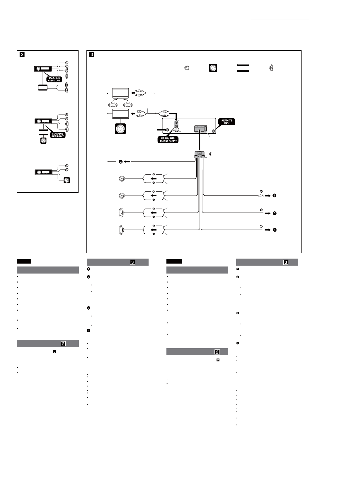
1
RCA pin cord (not supplied).
*
2
*
AUDIO OUT can be switched SUB or REAR. For details, see the
supplied Operating Instructions.
3
Separate adaptor may be required.
*
*1 Cable con terminales RCA (no suministrado).
2
AUDIO OUT (salida de audio) puede cambiarse a SUB o REAR.
*
Para obtener información, consulte el manual de instrucciones
suministrado.
3
*
Puede requerirse un adaptador independiente.
BATTERY
Rear speaker
Altavoz posterior
ACC
English
Cautions
is unit is designed for negative ground (earth) 12 V
DC operation only.
Do not get the leads under a screw, or caught in moving
parts (e.g. seat railing).
Before making connections, turn the car ignition off to
avoid short circuits.
Connect the yellow and red power supply leads only
after all other leads have been connected.
Run all ground (earth) leads to a common ground
(earth) point.
Be sure to insulate any loose unconnected leads with
electrical tape for safety.
e use of optical instruments with this product will
increase eye hazard.
Notes on the power supply lead (yellow)
When connecting this unit in combination with other
stereo components, the connected car circuit’s rating
must be higher than the sum of each component’s fuse.
When no car circuits are rated high enough, connect the
unit directly to the battery.
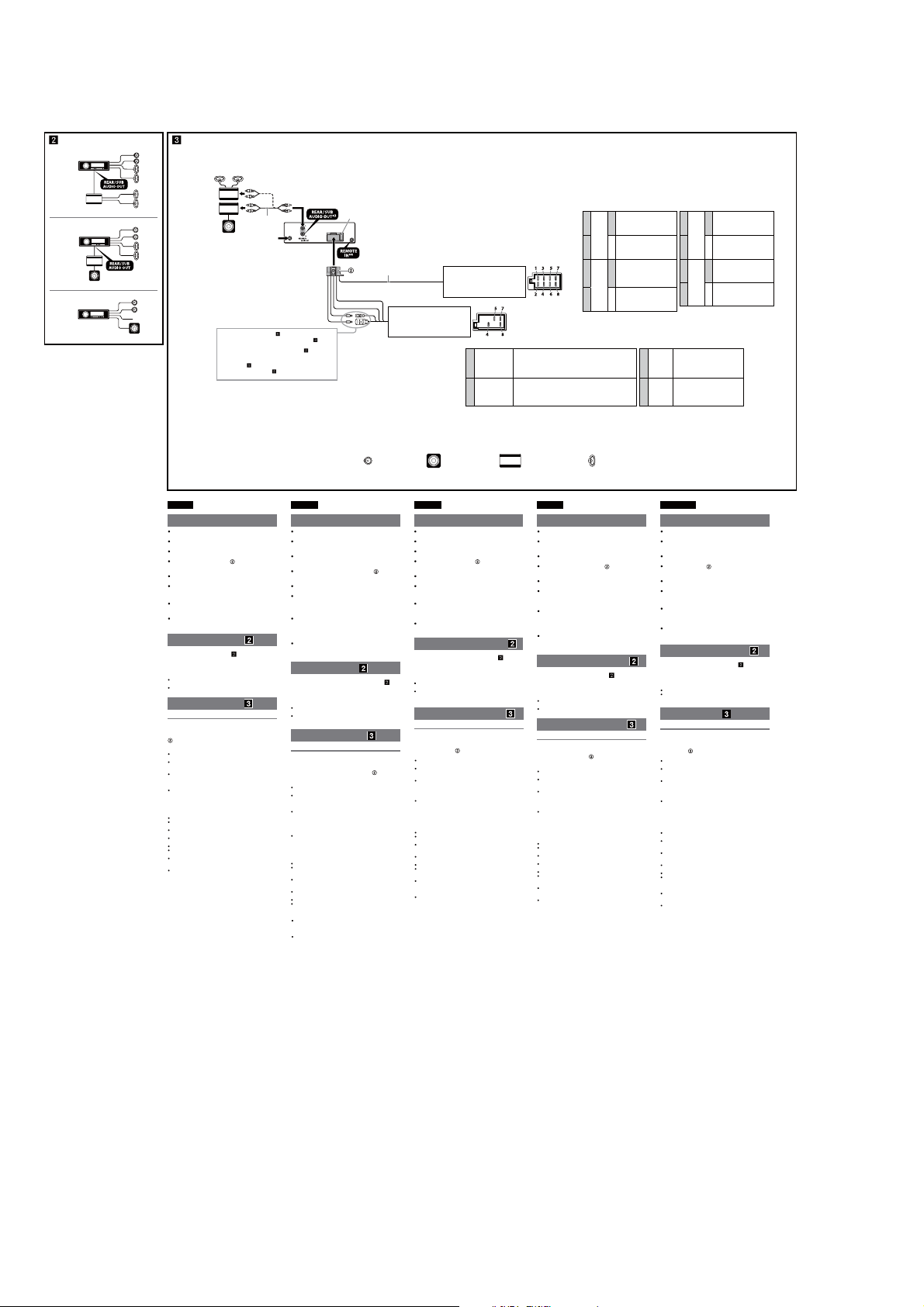
Connection example ( )
Subwoofer Direct Connection ( -C)
For details on the setting for the connection, see the
supplied Operating Instruction.
* Do not connect a speaker in this connection.
Notes
Be sure to connect the ground (earth) lead before connecting the
amplier.
The alarm will only sound if the built-in amplier is used.
Connection diagram ( )
To a metal surface of the car
First connect the black ground (earth) lead, then connect the yellow
and red power supply leads.
To the power antenna (aerial) control lead or
power supply lead of antenna (aerial) booster
Notes
It is not necessary to connect this lead if there is no power antenna
(aerial) or antenna (aerial) booster, or with a manually-operated
telescopic antenna (aerial).
When your car has a built-in FM/AM antenna (aerial) in the rear/
side glass, see “Notes on the control and power supply leads.”
To AMP REMOTE IN of an optional power
amplier
This connection is only for ampliers and a power antenna (aerial).
Connecting any other system may damage the unit.
To the +12 V power terminal which is energized
in the accessory position of the ignition switch
Notes
If there is no accessory position, connect to the +12 V power
(battery) terminal which is energized at all times.
Be sure to connect the black ground (earth) lead to a metal surface
of the car rst.
When your car has a built-in FM/AM antenna (aerial) in the rear/
side glass, see “Notes on the control and power supply leads.”
To the +12 V power terminal which is energized
at all times
Be sure to connect the black ground (earth) lead to a metal surface of
the car rst.
Notes on the control and power supply leads
REM OUT lead (blue/white striped) supplies +12 V DC when you turn on
the unit.
When your car has built-in FM/AM antenna (aerial) in the rear/side
glass, connect REM OUT lead (blue/white striped) or the accessory
power supply lead (red) to the power terminal of the existing antenna
(aerial) booster. For details, consult your dealer.
A power antenna (aerial) without a relay box cannot be used with this
unit.
Memory hold connection
When the yellow power supply lead is connected, power will always be
supplied to the memory circuit even when the ignition switch is turned o.
Notes on speaker connection
Before connecting the speakers, turn the unit o.
Use speakers with an impedance of 4 to 8 ohms, and with adequate
power handling capacities to avoid its damage.
Do not connect the speaker terminals to the car chassis, or connect the
terminals of the right speakers with those of the left speaker.
Do not connect the ground (earth) lead of this unit to the negative (–)
terminal of the speaker.
Do not attempt to connect the speakers in parallel.
Connect only passive speakers. Connecting active speakers (with
built-in ampliers) to the speaker terminals may damage the unit.
To avoid a malfunction, do not use the built-in speaker leads installed in
your car if the unit shares a common negative (–) lead for the right and
left speakers.
Do not connect the unit’s speaker leads to each other.
Note on connection
If speaker and amplier are not connected correctly, “FAILURE” appears in
the display. In this case, make sure the speaker and amplier are
connected correctly.
Español
Precauciones
Esta unidad ha sido diseñada para alimentarse sólo con
cc de 12 V de masa negativa.
No coloque los cables debajo de ningún tornillo, ni los
aprisione con partes móviles (p. ej. los rieles del asiento).
Antes de realizar las conexiones, apague el automóvil
para evitar cortocircuitos.
Conecte los cables de fuente de alimentación amarillo y
rojo solamente después de haber conectado los demás.
Conecte todos los cables de conexión a masa a un
punto común.
Por razones de seguridad, asegúrese de aislar con cinta
aislante los cables sueltos que no estén conectados.
El uso de instrumentos ópticos con este producto
aumenta el riesgo de sufrir daños oculares.
Notas sobre el cable de fuente de alimentación
(amarillo)
Cuando conecte esta unidad en combinación con otros
componentes estéreo, la capacidad nominal del circuito
conectado del automóvil debe ser superior a la suma del
fusible de cada componente.
Si no hay circuitos del automóvil con capacidad nominal
suficientemente alta, conecte la unidad directamente a la
batería.
Ejemplo de conexiones ( )
Conexión directa de altavoz de subgraves ( -C)
Para obtener más información sobre cómo configurar la
conexión, consulte el Manual de instrucciones
suministrado.
* No conecte un altavoz a esta conexión.
Notas
Asegúrese de conectar primero el cable de conexión a masa antes de
realizar la conexión del amplicador.
La alarma sonará únicamente si se utiliza el amplicador incorporado.
Diagrama de conexión ( )
A una supercie metálica del automóvil
Conecte primero el cable de conexión a masa negro, y después los
cables amarillo y rojo de fuente de alimentación.
Al cable de control de la antena motorizada o al
cable de fuente de alimentación del amplicador
de señal de la antena
Notas
Si no se dispone de antena motorizada ni de amplicador de señal
de la antena, o se utiliza una antena telescópica accionada
manualmente, no será necesario conectar este cable.
Si el automóvil tiene una antena de FM/AM incorporada en el
cristal trasero o lateral, consulte “Notas sobre los cables de control
y de fuente de alimentación”.
A AMP REMOTE IN de un amplicador de
potencia opcional
Esta conexión es sólo para amplicadores y una antena motorizada.
La conexión de cualquier otro sistema puede dañar la unidad.
Al terminal de alimentación de +12 V que recibe
energía en la posición de accesorio del
interruptor de encendido
Notas
Si no hay posición de accesorio, conéctelo al terminal de
alimentación (batería) de +12 V que recibe energía sin
interrupción.
Asegúrese de conectar primero el cable de conexión a masa negro
a una supercie metálica del automóvil.
Si el automóvil tiene una antena de FM/AM incorporada en el
cristal trasero o lateral, consulte “Notas sobre los cables de control
y de fuente de alimentación”.
Al terminal de alimentación de +12 V que recibe
energía sin interrupción
Asegúrese de conectar primero el cable de conexión a masa negro a
una supercie metálica del automóvil.
Notas sobre los cables de control y de fuente de alimentación
El cable REM OUT (rayado azul y blanco) suministra cc +12 V al
encender la unidad.
Si el automóvil dispone de una antena de FM/AM incorporada en el
cristal trasero o lateral, conecte el cable REM OUT (rayado azul y
blanco) o el cable de fuente de alimentación auxiliar (rojo) al terminal
de alimentación del amplicador de señal de la antena existente. Para
obtener más detalles, consulte a su distribuidor.
Con esta unidad no es posible utilizar una antena motorizada sin caja
de relé.
Conexión para protección de la memoria
Si conecta el cable de fuente de alimentación amarillo, el circuito de la
memoria recibirá siempre alimentación, aunque apague el interruptor de
encendido.
Notas sobre la conexión de los altavoces
Antes de conectar los altavoces, desconecte la alimentación de la
unidad.
Utilice altavoces con una impedancia de 4 a 8 Ω con la capacidad de
potencia adecuada para evitar que se dañen.
No conecte los terminales de altavoz al chasis del automóvil, ni conecte
los terminales del altavoz derecho con los del izquierdo.
No conecte el cable de conexión a masa de esta unidad al terminal
negativo (–) del altavoz.
No intente conectar los altavoces en paralelo.
Conecte solamente altavoces pasivos. Si conecta altavoces activos (con
amplicadores incorporados) a los terminales de altavoz, puede dañar
la unidad.
Para evitar fallas de funcionamiento, no utilice los cables de altavoz
incorporados instalados en el automóvil si la unidad comparte un cable
negativo común (–) para los altavoces derecho e izquierdo.
No conecte los cables de altavoz de la unidad entre sí.
Nota sobre la conexión
Si el altavoz y el amplicador no están conectados correctamente,
aparecerá “FAILURE” en la pantalla. Si es así, compruebe la conexión de
ambos dispositivos.
6
CDX-GT57UPW/GT62UMI/GT570UE/GT570UI/GT570UP/GT574UI/GT620UI/GT626UI
1
2
3
A TOYOTA
size
5 × max. 8 mm
7
/32 × max. 5/16 in)
(
Tamaño
5 × 8 mm máx.
B NISSAN
size
5 × max. 8 mm
7
/32 × max. 5/16 in)
(
Tamaño
5 × 8 mm máx.
Face the hook inwards.
El gancho debe encontrarse
en la parte interior.
Screw
Tornillo
Bracket
Soporte
Existing parts supplied with your car
Piezas existentes suministradas con su automóvil
Box
Compartimento
to dashboard/center console
al tablero o consola central
Bracket
Soporte
to dashboard/center console
al tablero o consola central
size
5 × max. 8 mm
7
/32 × max. 5/16 in)
(
Tamaño
5 × 8 mm máx.
1
2
3
A
B
1
182 mm (7
/4 in)
Catch
Enganche
Claws
Uñas
Dashboard
Tablero
Front panel release button
Botón de liberación del panel
frontal
53 mm
(2
English
Precautions
Choose the installation location carefully so that the unit
will not interfere with normal driving operations.
Avoid installing the unit in areas subject to dust, dirt,
excessive vibration, or high temperatures, such as in
direct sunlight or near heater ducts.
1
/8 in)
Use only the supplied mounting hardware for a safe and
secure installation.
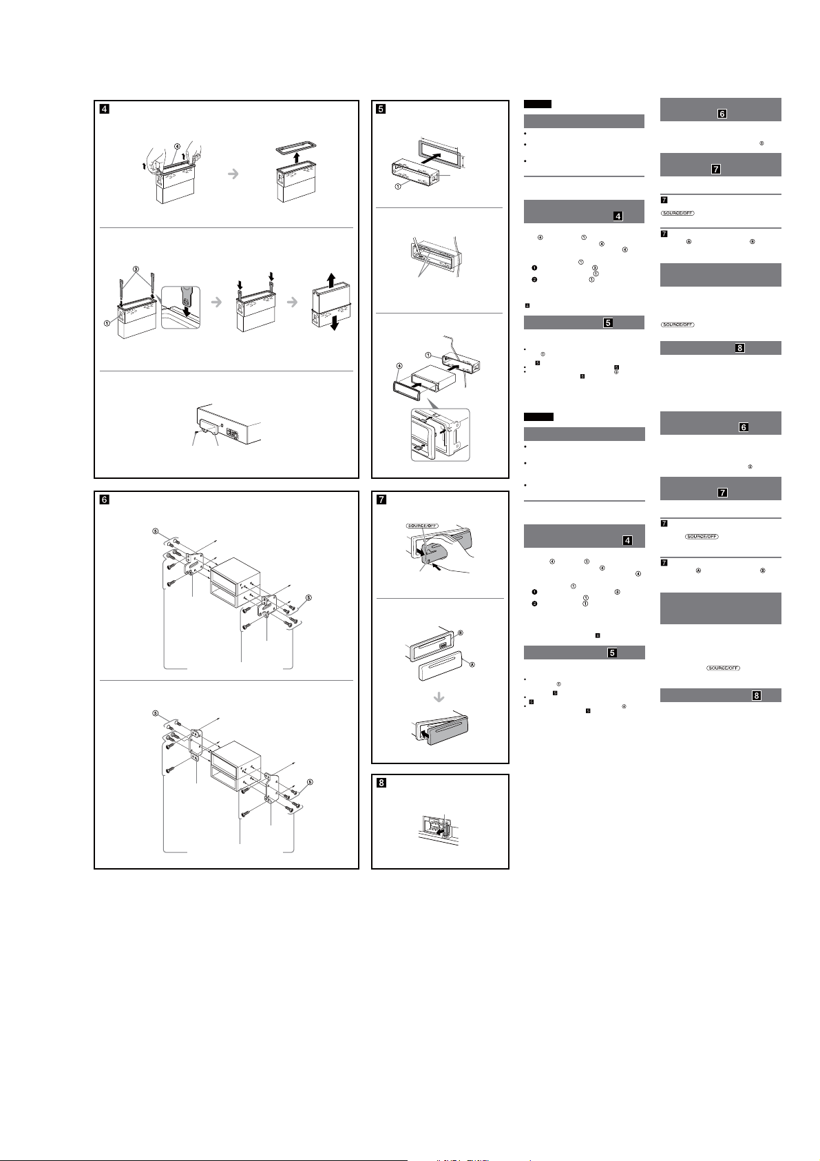
Mounting angle adjustment
Adjust the mounting angle to less than 45°.
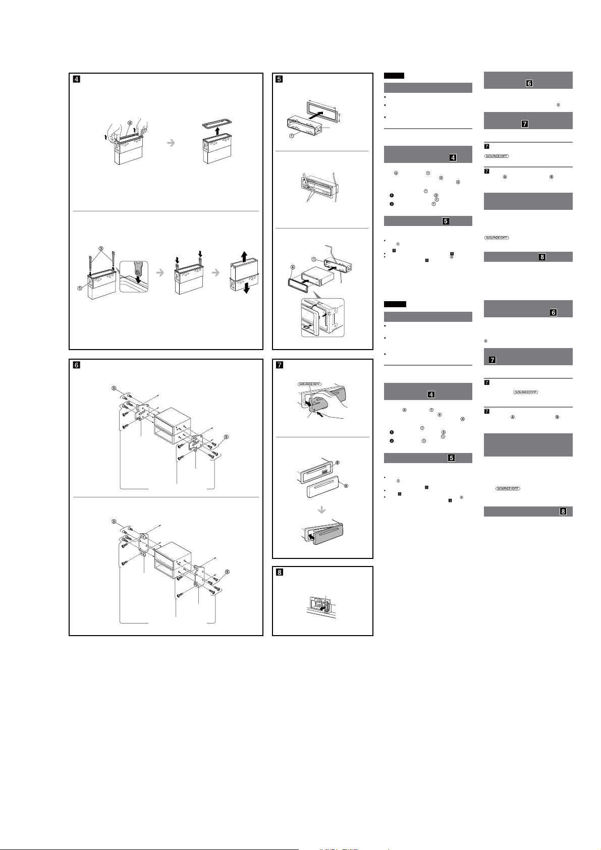
Removing the protection
collar and the bracket (
Before installing the unit, remove the protection
and the bracket from the unit.
collar
Remove the protection collar .
1
Pinch both edges of the protection collar , then
pull it out.
Remove the bracket .
2
Insert both release keys together between
the unit and the bracket
Pull down the bracket , then pull up the unit
to separate.
Note
Before installing this unit, remove the screw and box on the back of the
unit. Do not use the previous parts you removed when installing the unit
(
-3).
)
until they click.
Mounting example ( )
Installation in the dashboard
Notes
Before installing, make sure that the catches on both sides of the
bracket are bent inwards 2 mm (
bent outwards, the unit will not be installed securely and may spring
out ( -1).
Bend these claws outward for a tight t, if necessary ( -2).
Make sure that the 4 catches on the protection collar are properly
engaged in the slots of the unit (
3
/32 in). If the catches are straight or
-3).
Español
Precauciones
Elija cuidadosamente el lugar de montaje de forma que
la unidad no interera con las funciones normales de
conducción.
Evite instalar la unidad donde pueda quedar expuesta a
polvo, suciedad, vibraciones excesivas o altas
temperaturas, por ejemplo, a la luz solar directa o cerca
de conductos de calefacción.
Para realizar una instalación segura y rme, utilice
solamente elementos de instalación suministrados.
Ajuste del ángulo de montaje
Ajuste el ángulo de montaje a menos de 45°.
Extracción del marco de
protección y del soporte (
Antes de instalar la unidad, retire el marco de
y el soporte de la misma.
protección
Retire el marco de protección .
1
Apriete ambos bordes del marco de protección
y, a continuación, tire de él hacia fuera.
Retire el soporte .
2
Inserte ambas llaves de liberación entre la
unidad y el soporte hasta que encajen.
Presione el soporte y, a continuación,
levante la unidad para separar ambos
elementos.
Nota
Antes de instalar esta unidad, extraiga el tornillo y el compartimento que
se encuentran en la parte posterior de la unidad. No utilice las piezas
anteriores que extrajo al instalar la unidad (
-3).
Ejemplo de montaje ( )
Instalación en el tablero
Notas
Antes de instalar la unidad, compruebe que los enganches de ambos
estén doblados hacia adentro 2 mm. Si no lo están
lados del soporte
o están doblados hacia afuera, la unidad no se instalará correctamente
y puede saltar (
-1).
Si es necesario, doble las uñas hacia fuera para que encaje rmemente
( -2).
Compruebe que los 4 enganches del marco de protección estén bien
jados en las ranuras de la unidad (
-3).
Mounting the unit in a
Japanese car (
You may not be able to install this unit in some makes of
Japanese cars. In such a case, consult your Sony dealer.
Note
To prevent malfunction, install only with the supplied screws
How to detach and attach the
front panel (
Before installing the unit, detach the front panel.
-A To detach
Before detaching the front panel, be sure to press and hold
. Press the front panel release button, and
pull it off towards you.
-B To attach
Engage part of the front panel with part of the unit,
as illustrated, and push the le side into position until it
clicks.
Warning if your car’s ignition
has no ACC position
Be sure to set the Auto Off function. For details, see the
supplied Operating Instructions.
e unit will shut off completely and automatically in the
set time aer the unit is turned off, which prevents battery
drain.
If you do not set the Auto Off function, press and hold
until the display disappears each time
you turn the ignition off.
Fuse replacement ( )
When replacing the fuse, be sure to use one matching the
amperage rating stated on the original fuse. If the fuse
blows, check the power connection and replace the fuse. If
the fuse blows again after replacement, there may be an
internal malfunction. In such a case, consult your nearest
Sony dealer.
Montaje de la unidad en un
automóvil japonés (
Es posible que no pueda instalar esta unidad en algunos
automóviles japoneses. En tal caso, consulte a su
distribuidor Sony.
Nota
Para evitar que se produzcan fallas de funcionamiento, realice la
instalación solamente con los tornillos suministrados
Forma de extraer e instalar el
panel frontal (
Antes de instalar la unidad, extraiga el panel frontal.
-A Para extraerlo
Antes de extraer el panel frontal, asegúrese de mantener
presionado
)
liberación del panel frontal y extraiga el panel frontal hacia
usted.
-B Para instalarlo
Coloque la parte del panel frontal en la parte de la
unidad, como se muestra en la ilustración, y después
presione la parte izquierda hasta que encaje.
Advertencia: si el encendido
del automóvil no dispone de
una posición ACC
Asegúrese de ajustar la función de desconexión
automática. Para obtener más información, consulte el
manual de instrucciones suministrado.
La unidad se apagará completa y automáticamente en el
tiempo establecido después de que se desconecte la
unidad, lo que evita que se desgaste la batería.
Si no ha ajustado la función de desconexión automática,
mantenga presionado
apague el interruptor de encendido, hasta que la pantalla
desaparezca.
Sustitución del fusible ( )
Al sustituir el fusible, asegúrese de utilizar uno cuyo
amperaje coincida con el especicado en el original. Si el
fusible se funde, verique la conexión de alimentación y
sustitúyalo. Si el fusible vuelve a fundirse después de
sustituirlo, es posible que exista alguna falla de
funcionamiento interno. En tal caso, consulte con el
distribuidor Sony más cercano.
)
.
)
)
.
)
. Presione el botón de
cada vez que
Bracket
Soporte
Bracket
Soporte
Existing parts supplied with your car
Piezas existentes suministradas con su automóvil
size
5 × max. 8 mm
7
(
/32 × max. 5/16 in)
Tamaño
5 × 8 mm máx.
Fuse (10 A)
Fusible (10 A)
7
CDX-GT57UPW/GT62UMI/GT570UE/GT570UI/GT570UP/GT574UI/GT620UI/GT626UI
(CDX-GT570UP)
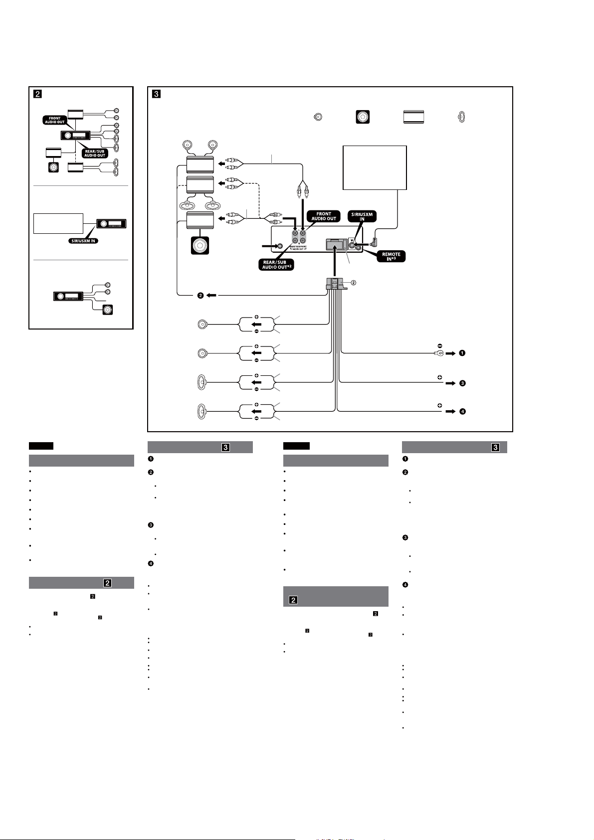
Equipment used in illustrations (not supplied)
A
Appareils utilisés dans les illustrations (non fournis)
B
Satellite radio tuner
1
(SiriusXM)*
Syntoniseur radio satellite
1
*
(SiriusXM)
C
Front speaker
Haut-parleur avant
1
*
1
*
from car antenna (aerial)
à partir de l’antenne
du véhicule
REM OUT
2
*
Left
Gauche
Right
Droit
Left
Gauche
Right
Droit
Max. supply current 0.4 A
Courant max. fourni 0,4 A
Blue/white striped
Rayé bleu/blanc
White
Blanc
White/black striped
Rayé blanc/noir
Gray
Gris
Gray/black striped
Rayé gris/noir
Green
Vert
Green/black striped
Rayé vert/noir
Purple
Violet
Purple/black striped
Rayé violet/noir
Subwoofer
Caisson de graves
Satellite radio tuner
4
(SiriusXM)*
Syntoniseur radio satellite
4
(SiriusXM)*
Fuse (10 A)
Fusible (10 A)
Black
Noir
Red
Rouge
Yellow
Jaune
Power amplier
Amplicateur de puissance
*1 RCA pin cord (not supplied).
2
*
AUDIO OUT can be switched SUB or REAR. For details, see the
supplied Operating Instructions.
3
*
Separate adaptor may be required.
4
*
not supplied
1
*
Cordon à broche RCA (non fourni).
2
AUDIO OUT peut être commuté sur SUB ou REAR. Pour obtenir
*
plus de détails, reportez-vous au mode d’emploi fourni.
3
*
L’utilisation d’un adaptateur pourrait être nécessaire.
4
*
non fourni
ACC
BATTERY
Rear speaker
Haut-parleur arrière
English
Cautions
is unit is designed for negative ground (earth) 12 V
DC operation only.
Do not get the leads under a screw, or caught in moving
parts (e.g. seat railing).
Before making connections, turn the car ignition off to
avoid short circuits.
Connect the yellow and red power supply leads only
after all other leads have been connected.
Run all ground (earth) leads to a common ground
(earth) point.
Be sure to insulate any loose unconnected leads with
electrical tape for safety.
e use of optical instruments with this product will
increase eye hazard.
Notes on the power supply lead (yellow)
When connecting this unit in combination with other
stereo components, the connected car circuit’s rating
must be higher than the sum of each component’s fuse.
When no car circuits are rated high enough, connect the
unit directly to the battery.
Connection example ( )
Subwoofer Direct Connection ( -C)
For details on the setting for the connection, see the
supplied Operating Instruction.
*1 not supplied ( -B)
2
Do not connect a speaker in this connection ( -C).
*
Notes
Be sure to connect the ground (earth) lead before connecting the
amplier.
The alarm will only sound if the built-in amplier is used.
Connection diagram ( )
To a metal surface of the car
First connect the black ground (earth) lead, then connect the yellow
and red power supply leads.
To the power antenna (aerial) control lead or
power supply lead of antenna (aerial) booster
Notes
It is not necessary to connect this lead if there is no power antenna
(aerial) or antenna (aerial) booster, or with a manually-operated
telescopic antenna (aerial).
When your car has a built-in FM/AM antenna (aerial) in the rear/
side glass, see “Notes on the control and power supply leads.”
To AMP REMOTE IN of an optional power
amplier
This connection is only for ampliers and a power antenna (aerial).
Connecting any other system may damage the unit.
To the +12 V power terminal which is energized
in the accessory position of the ignition switch
Notes
If there is no accessory position, connect to the +12 V power
(battery) terminal which is energized at all times.
Be sure to connect the black ground (earth) lead to a metal surface
of the car rst.
When your car has a built-in FM/AM antenna (aerial) in the rear/
side glass, see “Notes on the control and power supply leads.”
To the +12 V power terminal which is energized
at all times
Be sure to connect the black ground (earth) lead to a metal surface of
the car rst.
Notes on the control and power supply leads
REM OUT lead (blue/white striped) supplies +12 V DC when you turn on
the unit.
When your car has built-in FM/AM antenna (aerial) in the rear/side
glass, connect REM OUT lead (blue/white striped) or the accessory
power supply lead (red) to the power terminal of the existing antenna
(aerial) booster. For details, consult your dealer.
A power antenna (aerial) without a relay box cannot be used with this
unit.
Memory hold connection
When the yellow power supply lead is connected, power will always be
supplied to the memory circuit even when the ignition switch is turned o.
Notes on speaker connection
Before connecting the speakers, turn the unit o.
Use speakers with an impedance of 4 to 8 ohms, and with adequate
power handling capacities to avoid its damage.
Do not connect the speaker terminals to the car chassis, or connect the
terminals of the right speakers with those of the left speaker.
Do not connect the ground (earth) lead of this unit to the negative (–)
terminal of the speaker.
Do not attempt to connect the speakers in parallel.
Connect only passive speakers. Connecting active speakers (with
built-in ampliers) to the speaker terminals may damage the unit.
To avoid a malfunction, do not use the built-in speaker leads installed in
your car if the unit shares a common negative (–) lead for the right and
left speakers.
Do not connect the unit’s speaker leads to each other.
Note on connection
If speaker and amplier are not connected correctly, “FAILURE” appears in
the display. In this case, make sure the speaker and amplier are
connected correctly.
Français
Précautions
Cet appareil est exclusivement conçu pour fonctionner
sur une tension de 12 V CC avec masse négative.
Évitez de xer des vis sur les câbles ou de coincer ceux-ci
dans des pièces mobiles (par exemple, armature de siège).
Avant d’eectuer les raccordements, coupez le moteur
pour éviter un court-circuit.
Raccordez les câbles d’alimentation jaune et rouge
seulement après avoir terminé tous les autres
raccordements.
Rassemblez tous les câbles de mise à la masse en
un point de masse commun.
Pour des raisons de sécurité, veillez à isoler avec du
ruban isolant tout câble libre non raccordé.
L’utilisation d’instruments optiques avec ce produit
augmente les risques pour les yeux.
Remarques sur le câble d’alimentation (jaune)
Lorsque cet appareil est raccordé à d’autres éléments
stéréo, la valeur nominale du circuit de la voiture
raccordé doit être supérieure à la somme des fusibles de
chaque élément.
Si aucun circuit de la voiture n’est assez puissant,
raccordez directement l’appareil à la batterie.
Exemple de raccordement
(
)
Raccordement direct d’un caisson de graves ( -C)
Pour plus de détails sur le réglage pour le raccordement,
reportez-vous au mode d’emploi fourni.
*1 non fourni ( -B)
2
Ne raccordez pas un haut-parleur avec cette connexion ( -C).
*
Remarques
Raccordez d’abord le câble de mise à la masse avant de raccorder
l’amplicateur.
L’alarme est émise uniquement lorsque l’amplicateur intégré est utilisé.
Schéma de raccordement ( )
À un point métallique de la voiture
Branchez d’abord le câble de mise à la masse noir et, ensuite, les
câbles d’alimentation jaune et rouge.
Au câble de commande d’antenne électrique ou
au câble d’alimentation de l’amplicateur
d’antenne
Remarques
Il n’est pas nécessaire de raccorder ce câble s’il n’y a pas d’antenne
électrique ni d’amplicateur d’antenne, ou avec une antenne
télescopique manuelle.
Si votre voiture est équipée d’une antenne FM/AM intégrée dans la
vitre arrière/latérale, voir « Remarques sur les câbles de commande
et d’alimentation ».
Au niveau de AMP REMOTE IN de l’amplicateur
de puissance en option
Ce raccordement s’applique uniquement aux amplicateurs et à une
antenne électrique. Le branchement de tout autre système risque
d’endommager l’appareil.
À la borne d’alimentation +12 V qui est alimentée
quand la clé de contact est sur la position
accessoires
Remarques
S’il n’y a pas de position accessoires, raccordez la borne
d’alimentation (batterie) +12 V qui est alimentée en permanence.
Raccordez d’abord le câble de mise à la masse noir à un point
métallique du véhicule.
Si votre voiture est équipée d’une antenne FM/AM intégrée dans la
vitre arrière/latérale, voir « Remarques sur les câbles de commande
et d’alimentation ».
À la borne d’alimentation +12 V qui est alimentée
en permanence
Raccordez d’abord le câble de mise à la masse noir à un point
métallique du véhicule.
Remarques sur les câbles de commande et d’alimentation
Le câble REM OUT (rayé bleu/blanc) fournit une alimentation de +12 V
CC lorsque vous mettez l’appareil en marche.
Lorsque votre voiture est équipée d’une antenne FM/AM intégrée dans
la vitre arrière/latérale, raccordez le câble REM OUT (rayé bleu/blanc) ou
le câble d’alimentation des accessoires (rouge) à la borne
d’alimentation de l’amplicateur d’antenne existant. Pour plus de
détails, consultez votre détaillant.
Une antenne électrique sans boîtier de relais ne peut pas être utilisée
avec cet appareil.
Raccordement pour la conservation de la mémoire
Lorsque le câble d’alimentation jaune est raccordé, le circuit de la
mémoire est alimenté en permanence même si la clé de contact est sur la
position d’arrêt.
Remarques sur le raccordement des haut-parleurs
Avant de raccorder les haut-parleurs, éteignez l'appareil.
Utilisez des haut-parleurs ayant une impédance de 4 à 8 ohms avec une
capacité électrique adéquate pour éviter de les endommager.
Ne raccordez pas les bornes du système de haut-parleurs au châssis de
la voiture et ne raccordez pas les bornes du haut-parleur droit à celles
du haut-parleur gauche.
Ne raccordez pas le câble de mise à la masse de cet appareil à la borne
négative (–) du haut-parleur.
N’essayez pas de raccorder les haut-parleurs en parallèle.
Raccordez uniquement des haut-parleurs passifs. Le raccordement de
haut-parleurs actifs (avec amplicateurs intégrés) aux bornes des
haut-parleurs peut endommager l’appareil.
Pour éviter tout problème de fonctionnement, n’utilisez pas les câbles
des haut-parleurs intégrés installés dans votre voiture si l’appareil
possède un câble négatif commun (–) pour les haut-parleurs droit et
gauche.
Ne raccordez pas entre eux les cables des haut-parleurs de l’appareil.
Remarque sur le raccordement
Si le haut-parleur et l’amplicateur ne sont pas raccordés correctement, le
message « FAILURE » s’ache. Dans ce cas, assurez-vous que les
haut-parleurs et l’amplicateur sont bien raccordés.
8
CDX-GT57UPW/GT62UMI/GT570UE/GT570UI/GT570UP/GT574UI/GT620UI/GT626UI
1
2
A TOYOTA
size
5 × max. 8 mm
7
/32 × max. 5/16 in)
(
dimension
5 × max. 8 mm
7
/32 × 5/16 po max.)
(
B NISSAN
size
5 × max. 8 mm
7
/32 × max. 5/16 in)
(
dimension
5 × max. 8 mm
7
/32 × 5/16 po max.)
(
Face the hook inwards.
Tournez le crochet vers
l’intérieur.
Bracket
Support
to dashboard/center console
vers le tableau de bord/la console centrale
Bracket
Support
Existing parts supplied with your car
Pièces existantes fournies avec la voiture
to dashboard/center console
vers le tableau de bord/la console centrale
size
5 × max. 8 mm
7
/32 × max. 5/16 in)
(
dimension
5 × max. 8 mm
7
(
/32 × 5/16 po max.)
1
2
3
A
B
1
/4)
182 (7
Claws
Gries
Dashboard
Tableau de bord
Front panel release button
Touche de déverrouillage de
la façade
Catch
Loquet
Unit: mm (in)
Unité: mm (po)
1
53 (2
English
Precautions
Choose the installation location carefully so that the unit
will not interfere with normal driving operations.
Avoid installing the unit in areas subject to dust, dirt,
excessive vibration, or high temperatures, such as in
direct sunlight or near heater ducts.
/8)
Use only the supplied mounting hardware for a safe and
secure installation.
Mounting angle adjustment
Adjust the mounting angle to less than 45°.
Removing the protection
collar and the bracket (
Before installing the unit, remove the protection
and the bracket from the unit.
collar
Remove the protection collar .
1
Pinch both edges of the protection collar , then
pull it out.
Remove the bracket .
2
Insert both release keys together between
the unit and the bracket
Pull down the bracket , then pull up the unit
to separate.
)
until they click.
Mounting example ( )
Installation in the dashboard
Notes
Before installing, make sure that the catches on both sides of the
bracket are bent inwards 2 mm (
bent outwards, the unit will not be installed securely and may spring
-1).
out (
Bend these claws outward for a tight t, if necessary ( -2).
Make sure that the 4 catches on the protection collar are properly
engaged in the slots of the unit (
3
/32 in). If the catches are straight or
-3).
Français
Précautions
Choisissez soigneusement l’emplacement d’installation
pour que l’appareil ne gêne pas le conducteur pendant la
conduite.
Évitez d’installer l’appareil dans un endroit exposé à la
poussière, à la saleté, à des vibrations excessives ou à des
températures élevées comme en plein soleil ou à
proximité de conduits de chauage.
Pour garantir un montage sûr, n’utilisez que le matériel
fourni.
Réglage de l’angle de montage
Réglez l’inclinaison à un angle inférieur à 45°.
Retrait du tour de protection
et du support (
Avant d’installer l’appareil, retirez le tour de
protection
Retirez le tour de protection .
1
Pincez les deux bords du tour de protection ,
puis sortez-le.
Retirez le support .
2
Insérez les clés de déblocage en même temps
entre l’appareil et le support
Tirez le support vers le bas, puis tirez sur
l’appareil vers le haut pour les séparer.
)
et le support de l’appareil.
jusqu’au déclic.
Exemple de montage ( )
Installation dans le tableau de bord
Remarques
Avant l’installation, assurez-vous que les loquets des deux côtés du
support sont bien pliés de 2 mm (
sont droits ou pliés vers l’extérieur, l’appareil ne peut pas être xé
solidement et peut se détacher (
Si nécessaire, pliez ces gries vers l’extérieur pour assurer une prise
correcte (
Assurez-vous que les 4 loquets situés sur le tour de protection sont
correctement engagés dans les fentes de l’appareil (
-2).
3
/32 po) vers l’intérieur. Si les loquets
-1).
-3).
Mounting the unit in a
Japanese car (
You may not be able to install this unit in some makes of
Japanese cars. In such a case, consult your Sony dealer.
Note
To prevent malfunction, install only with the supplied screws .
How to detach and attach the
front panel (
Before installing the unit, detach the front panel.
-A To detach
Before detaching the front panel, be sure to press and hold
pull it off towards you.
-B To attach
Engage part of the front panel with part of the unit,
as illustrated, and push the le side into position until it
clicks.
Warning if your car’s ignition
has no ACC position
Be sure to set the Auto Off function. For details, see the
supplied Operating Instructions.
e unit will shut off completely and automatically in the
set time aer the unit is turned off, which prevents battery
drain.
If you do not set the Auto Off function, press and hold
you turn the ignition off.
)
)
. Press the front panel release button, and
until the display disappears each time
Fuse replacement ( )
When replacing the fuse, be sure to use one matching the
amperage rating stated on the original fuse. If the fuse
blows, check the power connection and replace the fuse. If
the fuse blows again after replacement, there may be an
internal malfunction. In such a case, consult your nearest
Sony dealer.
Montage de l’appareil dans
une voiture japonaise (
Cet appareil ne peut pas être installé dans certaines
voitures japonaises. Consultez, dans ce cas, votre détaillant
Sony.
Remarque
Pour éviter tout problème de fonctionnement, utilisez uniquement les vis
fournies pour le montage.
Retrait et xation de la façade
(
)
Avant d’installer l’appareil, retirez la façade.
-A Pour la retirer
Avant de retirer la façade, n’oubliez pas de maintenir
enfoncée la touche
touche de déverrouillage de la façade, puis faites glisser la
façade vers vous.
-B Pour la xer
Engagez la partie de la façade dans la partie de
l’appareil, comme illustré, puis appuyez sur le côté gauche
jusqu’au déclic indiquant que la façade est en position.
Avertissement si le contact de
votre véhicule ne comporte
pas de position ACC
Veillez à régler la fonction Auto Off. Pour obtenir
davantage d’informations, reportez-vous au mode d’emploi
fourni.
L’appareil s’éteint complètement et automatiquement après
le laps de temps choisi une fois l’appareil arrêté afin d’éviter
que la batterie ne se décharge.
Si vous ne réglez pas la fonction Auto Off, appuyez sur la
touche
ce que l’achage disparaisse à chaque fois que vous
coupez le contact.
et maintenez-la enfoncée jusqu’à
)
. Appuyez sur la
Remplacement du fusible ( )
Lorsque vous remplacez le fusible, veillez à utiliser un
fusible dont l’intensité, en ampères, correspond à la valeur
indiquée sur le fusible usagé. Si le fusible grille, vériez le
branchement de l’alimentation et remplacez le fusible. Si le
nouveau fusible grille également, il est possible que
l’appareil soit défectueux. Dans ce cas, consultez votre
détaillant Sony le plus proche.
Bracket
Support
Existing parts supplied with your car
Pièces existantes fournies avec la voiture
Bracket
Support
size
5 × max. 8 mm
7
(
/32 × max. 5/16 in)
dimension
5 × max. 8 mm
(7/32 × 5/16 po max.)
Fuse (10 A)
Fusible (10 A)
9
CDX-GT57UPW/GT62UMI/GT570UE/GT570UI/GT570UP/GT574UI/GT620UI/GT626UI
(CDX-GT570UI: AEP, UK/GT574UI: AEP, UK models)
1
*1 Depending on the type of car, use an adaptor (not
supplied) if the antenna connector does not t.
2
*
RCA pin cord (not supplied).
3
*
2
*
AUDIO OUT can be switched SUB or REAR. For details,
see the supplied Operating Instructions.
4
*
Separate adaptor may be required.
5
*
Speaker impedance: 4 – 8 ohms × 4
Fuse (10 A)
Sicherung (10 A)
Fusible (10 A)
Fusibile (10 A)
Zekering (10 A)
A
B
*1 from car antenna (aerial)
von Autoantenne
de l’antenne de la voiture
dall’antenna dell’auto
van een auto-antenne
C
*
See “Power connection diagram ( )” on the reverse side for details.
Näheres dazu nden Sie im „Stromanschlussdiagramm (
Blättern Sie dazu bitte um.
Voir le « Schéma de raccordement d’alimentation (
pour plus de détails.
Per ulteriori informazioni, vedere “Diagramma dei collegamenti di
)” che si trova sul retro.
alimentazione (
Zie "Voedingsaansluitschema (
details.
Equipment used in illustrations (not supplied)
In Abbildungen dargestellte Geräte (nicht mitgeliefert)
Appareils utilisés dans les illustrations (non fournis)
Apparecchiatura utilizzata nelle illustrazioni (non in dotazione)
Apparatuur gebruikt in de afbeeldingen (niet bijgeleverd)
) » au verso
)" op de achterkant voor meer
) “.
*
Abhängig vom Autotyp müssen Sie einen Adapter
(nicht mitgeliefert) verwenden, wenn der
Antennenanschluss nicht passt.
2
*
Cinchkabel (nicht mitgeliefert).
3
*
AUDIO OUT kann zwischen SUB und REAR
umgeschaltet werden. Näheres hierzu nden Sie in der
mitgelieferten Bedienungsanleitung.
4
*
Möglicherweise ist ein separater Adapter erforderlich.
5
*
Lautsprecherimpedanz: 4 – 8 Ohm × 4
5
*
from the car’s power connector
vom Stromanschluss des Fahrzeugs
du connecteur d’alimentation de la voiture
dal connettore di alimentazione dell’auto
van de autovoedingsaansluiting
Front speaker
Frontlautsprecher
Haut-parleur avant
Diusore anteriore
Voorluidspreker
from the car’s speaker connector
vom Lautsprecheranschluss des Fahrzeugs
du connecteur de haut-parleur de la voiture
dal connettore dei diusori dell’auto
van de autoluidsprekeraansluiting
Subwoofer
Tiefsttonlautsprecher
Caisson de graves
Subwoofer
Subwoofer
1
Selon le type de voiture, utilisez un adaptateur (non
*
fourni) si le connecteur de l’antenne ne convient pas.
2
*
Cordon à broche RCA (non fourni).
3
*
AUDIO OUT peut être commuté sur SUB ou REAR. Pour
obtenir plus de détails, reportez-vous au mode
d’emploi.
4
*
Un adaptateur séparé peut être nécessaire.
5
*
Impédance des haut-parleurs : 4 – 8 ohms × 4
Yellow
continuous power supply
Gelb
4
5
Positions 1, 2, 3, and 6 do not have pins.
An Position 1, 2, 3 und 6 benden sich keine Stifte.
Les positions 1, 2, 3 et 6 ne comportent pas de broches.
Le posizioni 1, 2, 3 e 6 non hanno piedini.
De posities 1, 2, 3 en 6 hebben geen pins.
permanente Stromversorgung
alimentation continue
Jaune
Giallo
alimentazione continua
Geel
continue voeding
power antenna (aerial) /power amplier control (REM OUT)
Blue/white striped
Steueranschluss für Motorantenne/Endverstärker (REM OUT)
Blauweiß gestreift
commande de l’antenne électrique/amplicateur de puissance (REM
Rayé bleu/blanc
OUT)
Rigato blu e bianco
antenna elettrica/controllo dell’amplicatore di potenza (REM OUT)
Blauw/wit gestreept
elektrische antenne / versterker (REM OUT)
Power amplier
Endverstärker
Amplicateur de puissance
Amplicatore di potenza
Eindversterker
1
*
In base al tipo di automobile, utilizzare un adattatore
(non in dotazione) nel caso in cui il connettore
dell’antenna non sia adatto.
2
*
Cavo a piedini RCA (non in dotazione).
3
*
AUDIO OUT può essere impostato su SUB o su REAR.
Per ulteriori informazioni, consultare il manuale di le
istruzioni per l’uso in dotazione.
4
*
Potrebbe essere necessario un adattatore separato.
5
*
Impedenza diusori: 4 – 8 ohm × 4
Speaker, Rear, Right
Lautsprecher hinten rechts
1
+
Haut-parleur, arrière, droit
Purple
Diusore, posteriore, destro
Violett
Luidspreker, achter, rechts
Violet
Speaker, Rear, Right
Viola
Lautsprecher hinten rechts
Paars
2–
Haut-parleur, arrière, droit
Diusore, posteriore, destro
Luidspreker, achter, rechts
Speaker, Front, Right
Lautsprecher vorne rechts
3
+
Haut-parleur, avant, droit
Gray
Diusore, anteriore, destro
Grau
Luidspreker, voor, rechts
Gris
Grigio
Speaker, Front, Right
Grijs
Lautsprecher vorne rechts
4–
Haut-parleur, avant, droit
Diusore, anteriore, destro
Luidspreker, voor, rechts
Negative polarity positions 2, 4, 6, and 8 have striped leads.
An den negativ gepolten Positionen 2, 4, 6 und 8 benden sich gestreifte Adern.
Les positions de polarité négative 2, 4, 6 et 8 sont dotées de cordons rayés.
Le posizioni a polarità negativa 2, 4, 6 e 8 hanno cavi rigati.
De posities voor negatieve polariteit (2, 4, 6 en 8) hebben gestreepte kabels.
Rear speaker
Hecklautsprecher
Haut-parleur arrière
Diusore posteriore
Achterluidspreker
7
8
Red
Rot
Rouge
Rosso
Rood
Black
Schwarz
Noir
Nero
Zwart
5
6–
7
8–
switched power supply
geschaltete Stromversorgung
alimentation commutée
alimentazione commutata
geschakelde voeding
ground (earth)
masse
masse
terra
aarding
1
Afhankelijk van het soort wagen gebruikt u een
*
adapter (niet meegeleverd) als de antenneconnector
niet past.
2
*
Tulpstekkersnoer (niet bijgeleverd).
3
*
AUDIO OUT kan worden ingesteld op SUB of REAR.
Raadpleeg de gebruiksaanwijzing voor meer
informatie.
4
*
Er is mogelijk een afzonderlijke adapter vereist.
5
*
Luidsprekerimpedantie: 4 – 8 ohm × 4
Speaker, Front, Left
Lautsprecher vorne links
+
Haut-parleur, avant, gauche
White
Diusore, anteriore, sinistro
Weiß
Luidspreker, voor, links
Blanc
Speaker, Front, Left
Bianco
Lautsprecher vorne links
Wit
Haut-parleur, avant, gauche
Diusore, anteriore, sinistro
Luidspreker, voor, links
Speaker, Rear, Left
Lautsprecher hinten links
+
Haut-parleur, arrière, gauche
Green
Diusore, posteriore, sinistro
Grün
Luidspreker, achter, links
Vert
Speaker, Rear, Left
Verde
Lautsprecher hinten links
Groen
Haut-parleur, arrière, gauche
Diusore, posteriore, sinistro
Luidspreker, achter, links
English
Cautions
is unit is designed for negative ground (earth) 12 V
DC operation only.
Do not get the leads under a screw, or caught in moving
parts (e.g. seat railing).
Before making connections, turn the car ignition off to
avoid short circuits.
Connect the power supply lead to the unit and
speakers before connecting it to the auxiliary power
connector.
Run all ground (earth) leads to a common ground
(earth) point.
Be sure to insulate any loose unconnected leads with
electrical tape for safety.
Notes on the power supply lead (yellow)
When connecting this unit in combination with other
stereo components, the connected car circuit’s rating
must be higher than the sum of each component’s fuse.
When no car circuits are rated high enough, connect the
unit directly to the battery.
Connection example ( )
Subwoofer Direct Connection ( -C)
For details on the setting for the connection, see the
supplied Operating Instruction.
* Do not connect a speaker in this connection.
Notes
Be sure to connect the ground (earth) lead before connecting the
amplier.
The alarm will only sound if the built-in amplier is used.
Connection diagram ( )
Warning
If you have a power antenna (aerial) without a relay box,
connecting this unit with the supplied power supply lead
may damage the antenna (aerial).
Notes on the control and power supply leads
REM OUT lead (blue/white striped) supplies +12 V DC when you turn on
the unit.
When using an optional power amplier, connect REM OUT lead (blue/
white striped) or the accessory power supply lead (red) to its AMP
REMOTE IN.
When your car has built-in FM/MW/LW antenna (aerial) in the rear/side
glass, connect REM OUT lead (blue/white striped) or the accessory
power supply lead (red) to the power terminal of the existing antenna
(aerial) booster. For details, consult your dealer.
A power antenna (aerial) without a relay box cannot be used with this
unit.
Memory hold connection
When the yellow power supply lead is connected, power will always be
supplied to the memory circuit even when the ignition switch is turned o.
Notes on speaker connection
Before connecting the speakers, turn the unit o.
Use speakers with an impedance of 4 to 8 ohms, and with adequate
power handling capacities to avoid its damage.
Do not connect the speaker terminals to the car chassis, or connect the
terminals of the right speakers with those of the left speaker.
Do not connect the ground (earth) lead of this unit to the negative (–)
terminal of the speaker.
Do not attempt to connect the speakers in parallel.
Connect only passive speakers. Connecting active speakers (with
built-in ampliers) to the speaker terminals may damage the unit.
To avoid a malfunction, do not use the built-in speaker leads installed in
your car if the unit shares a common negative (–) lead for the right and
left speakers.
Do not connect the unit’s speaker leads to each other.
Note on connection
If speaker and amplier are not connected correctly, “FAILURE” appears in
the display. In this case, make sure the speaker and amplier are
connected correctly.
Deutsch
Warnhinweise
Dieses Gerät ist ausschließlich für den Betrieb bei 12 V
Gleichstrom (negative Erdung) bestimmt.
Achten Sie darauf, dass die Kabel nicht unter einer
Schraube oder zwischen beweglichen Teilen wie
(z. B. in einer Sitzschiene eingeklemmt werden.).
Schalten Sie, bevor Sie irgendwelche Anschlüsse
vornehmen, die Zündung des Fahrzeugs aus, um
Kurzschlüsse zu vermeiden.
Verbinden Sie das Stromversorgungskabel mit dem
Gerät und den Lautsprechern, bevor Sie es mit dem
Hilfsstromanschluss verbinden.
Schließen Sie alle Erdungskabel an einen
gemeinsamen Massepunkt an.
Aus Sicherheitsgründen müssen alle losen, nicht
angeschlossenen Drähte mit Isolierband abgeklebt
werden.
Hinweise zum Stromversorgungskabel (gelb)
Wenn Sie dieses Gerät zusammen mit anderen
Stereokomponenten anschließen, muss der
Autostromkreis, an den die Geräte angeschlossen sind,
eine höhere Leistung aufweisen als die Summe der
Sicherungen der einzelnen Komponenten.
Wenn kein Autostromkreis eine so hohe Leistung
aufweist, schließen Sie das Gerät direkt an die Batterie
an.
Anschlussbeispiel ( )
Direktverbindung mit Tiefsttonlautsprecher ( -C)
Einzelheiten zur Einstellung für die Verbindung nden Sie
in der mitgelieferten Bedienungsanleitung.
* Schließen Sie an diesen Anschluss keinen Lautsprecher an.
Hinweise
Schließen Sie unbedingt zuerst das Massekabel an, bevor Sie den
Verstärker anschließen.
Der Warnton wird nur ausgegeben, wenn der integrierte Verstärker
verwendet wird.
Anschlussdiagramm ( )
Warnung
Wenn Sie eine Motorantenne ohne Relaiskästchen
verwenden, kann durch Anschließen dieses Geräts mit
dem mitgelieferten Stromversorgungskabel
Antenne beschädigt werden.
Hinweise zu den Steuer- und Stromversorgungsleitungen
Die REM OUT-Leitung (blauweiß gestreift) liefert +12 V Gleichstrom,
wenn Sie das Gerät einschalten.
Wenn Sie einen gesondert erhältlichen Endverstärker verwenden,
schließen Sie die REM OUT-Leitung (blauweiß gestreift) oder die
Stromversorgungsleitung für Zubehörgeräte (rot) an AMP REMOTE IN
an.
Wenn das Fahrzeug mit einer in der Heck-/Seitenfensterscheibe
integrierten FM (UKW)/MW/LW-Antenne ausgestattet ist, schließen Sie
die REM OUT-Leitung (blauweiß gestreift) oder die
Stromversorgungsleitung für Zubehörgeräte (rot) an den
Stromversorgungsanschluss des vorhandenen Antennenverstärkers an.
Einzelheiten dazu erhalten Sie bei Ihrem Händler.
Es kann nur eine Motorantenne mit Relaiskästchen angeschlossen
werden.
Stromversorgung des Speichers
Wenn die gelbe Stromversorgungsleitung angeschlossen ist, wird der
Speicher stets (auch bei ausgeschalteter Zündung) mit Strom versorgt.
Hinweise zum Lautsprecheranschluss
Schalten Sie das Gerät aus, bevor Sie die Lautsprecher anschließen.
Verwenden Sie Lautsprecher mit einer Impedanz zwischen 4 und 8 Ohm
und ausreichender Belastbarkeit. Ansonsten können die Lautsprecher
beschädigt werden.
Verbinden Sie die Lautsprecheranschlüsse nicht mit dem Wagenchassis
und verbinden Sie auch nicht die Anschlüsse des rechten mit denen des
linken Lautsprechers.
Verbinden Sie die Masseleitung dieses Geräts nicht mit dem negativen
(–) Lautsprecheranschluss.
Versuchen Sie nicht, Lautsprecher parallel anzuschließen.
An die Lautsprecheranschlüsse dieses Geräts dürfen nur
Passivlautsprecher angeschlossen werden. Schließen Sie keine
Aktivlautsprecher (Lautsprecher mit eingebauten Verstärkern) an, da
das Gerät sonst beschädigt werden könnte.
Um Fehlfunktionen zu vermeiden, verwenden Sie nicht die im Fahrzeug
installierten, integrierten Lautsprecherleitungen, wenn am Ende eine
gemeinsame negative (–) Leitung für den rechten und den linken
Lautsprecher verwendet wird.
Verbinden Sie nicht die Lautsprecherkabel des Geräts miteinander.
Hinweis zum Anschließen
Wenn Lautsprecher und Verstärker nicht richtig angeschlossen sind,
erscheint „FAILURE“ im Display. Vergewissern Sie sich in diesem Fall, dass
Lautsprecher und Verstärker richtig angeschlossen sind.
die
Français
Précautions
Cet appareil est conçu pour fonctionner uniquement sur
un courant continu de 12 V avec masse négative.
Evitez de coincer les câbles sous des vis ou dans des
pièces mobiles (par exemple, armature de siège).
Avant d’eectuer des raccordements, éteignez le moteur
pour éviter les courts-circuits.
Branchez le câble d’alimention sur l’appareil et les
haut-parleurs avant de le brancher sur le connecteur
d’alimentation auxiliaire.
Rassemblez tous les câbles de mise à la masse en
un point de masse commun.
Veillez à isoler tout câble lâche non raccordé avec du
ruban isolant.
Remarques sur le câble d’alimentation (jaune)
Lorsque cet appareil est raccordé à d’autres équipements
stéréo, la valeur nominale du circuit raccordé du
véhicule doit être supérieure à la somme des fusibles de
chaque élément.
Si aucun circuit de la voiture n’est assez puissant,
raccordez directement l’appareil à la batterie.
Exemple de raccordement ( )
Connexion directe du caisson de graves ( -C)
Pour plus d’informations sur l’établissement de la
connexion, reportez-vous au mode d’emploi fourni.
* Ne raccordez pas de haut-parleur à cette connexion.
Remarques
Raccordez d’abord le câble de mise à la masse avant de connecter
l’amplicateur.
L’alarme est émise uniquement lorsque l’amplicateur intégré est utilisé.
Schéma de raccordement
Avertissement
Si vous disposez d’une antenne électrique sans boîtier de
relais, le branchement de cet appareil au moyen du cordon
d’alimentation fourni
Remarques sur les câbles de commande et d’alimentation
Fil REM OUT (rayé bleu/blanc) fournit une tension de +12 V CC lors de la
mise sous tension de l’appareil.
Si vous utilisez un amplicateur de puissance en option, raccordez le l
REM OUT (rayé bleu/blanc) ou le l d’alimentation des accessoires
(rouge) à son AMP REMOTE IN.
Si votre véhicule est équipé d’une antenne FM/MW (PO)/LW (GO)
intégrée dans la vitre arrière/latérale, raccordez le l REM OUT (rayé
bleu/blanc) ou le l d’alimentation des accessoires (rouge) à la borne
d’alimentation de l’amplicateur d’antenne existant. Pour plus
d’informations, consultez votre revendeur.
Une antenne électrique sans boîtier de relais ne peut pas être utilisée
avec cet appareil.
Raccordement pour la conservation de la mémoire
Lorsque le câble d’alimentation jaune est raccordé, le circuit de la
mémoire est alimenté en permanence même si la clé de contact est en
position d’arrêt.
Remarques sur le raccordement des haut-parleurs
Avant de raccorder les haut-parleurs, mettre l’appareil hors tension.
Utiliser des haut-parleurs ayant une impédance de 4 à 8 ohms et une
capacité adéquate sous peine de les endommager.
Ne pas raccorder les bornes du système de haut-parleurs au châssis de
la voiture et ne pas connecter les bornes des haut-parleurs droit à celles
des haut-parleurs gauche.
Ne pas raccorder le câble de mise à la masse de cet appareil à la borne
négative (–) du haut-parleur.
Ne pas tenter de raccorder les haut-parleurs en parallèle.
Connecter uniquement des haut-parleurs passifs. La connexion de
haut-parleurs actifs (avec des amplicateurs intégrés) aux bornes des
haut-parleurs pourrait endommager l’appareil.
Pour éviter tout problème de fonctionnement, n’utilisez pas les câbles
des haut-parleurs intégrés (–) installés dans votre voiture si l’appareil
dispose d’un câble négatif commun pour les haut-parleurs droit et
gauche.
Ne raccordez pas entre eux les cordons des haut-parleurs de l’appareil.
Remarque sur le raccordement
Si les haut-parleurs et l’amplicateur ne sont pas raccordés correctement,
le message « FAILURE » s’ache. Dans ce cas, assurez-vous que les
haut-parleurs et l’amplicateur sont raccordés correctement.
( )
risque d’endommager l’antenne.
Italiano
Attenzione
Questo apparecchio è stato progettato per l’uso solo a 12
V CC con massa negativa.
Evitare che i cavi rimangano bloccati da una vite o
incastrati nelle parti mobili (ad esempio nelle guide
scorrevoli dei sedili).
Prima di eettuare i collegamenti, spegnere il motore
dell’automobile onde evitare di causare cortocircuiti.
Collegare il cavo di alimentazione all’apparecchio e ai
diusori prima di collegarlo al connettore di
alimentazione ausiliaria.
Portare tutti i cavi di messa a terra a un punto di
massa comune.
Per sicurezza, assicurarsi di isolare qualsiasi cavo non
collegato utilizzando del nastro adesivo.
Note sul cavo di alimentazione (giallo)
Se questo apparecchio viene collegato in combinazione
con altri componenti stereo, la potenza nominale dei
circuiti dell’automobile deve essere superiore a quella
prodotta dalla somma dei fusibili di ciascun
componente.
Se la potenza nominale dei circuiti dell’automobile non è
suciente, collegare l’apparecchio direttamente alla
batteria.
Esempio di collegamento ( )
Connessione diretta al subwoofer ( -C)
Per informazioni sull’impostazione della connessione,
vedere le istruzioni per l’uso in dotazione.
* Non collegare un diusore in questa connessione.
Note
Assicurarsi di collegare il cavo di terra prima di collegare l’apparecchio
all’amplicatore.
L’allarme viene emesso solo se è in uso l’amplicatore incorporato.
Schema di collegamento ( )
Avvertenza
Quando si collega l’apparecchio con il cavo di
alimentazione in dotazione
l’antenna elettrica se questa non dispone di scatola a relè.
Note sui cavi di controllo e di alimentazione
Il cavo REM OUT (rigato blu e bianco) fornisce alimentazione da +12 V
CC all’accensione dell’apparecchio.
Quando si utilizza un amplicatore di potenza opzionale, collegare il
cavo REM OUT (rigato blu e bianco) o il cavo di alimentazione
accessoria (rosso) al rispettivo AMP REMOTE IN.
Se l’automobile è dotata di antenna FM/MW/LW incorporata nel vetro
posteriore/laterale, collegare il cavo REM OUT (rigato blu e bianco) o il
cavo di alimentazione accessoria (rosso) al terminale di alimentazione
del preamplicatore dell’antenna esistente. Per ulteriori informazioni,
consultare il rivenditore.
Non è possibile usare un’antenna elettrica senza scatola a relè con
questo apparecchio.
Collegamento per la conservazione della memoria
Quando il cavo di ingresso alimentazione giallo è collegato, viene sempre
fornita alimentazione al circuito di memoria anche quando l’interruttore
di accensione è spento.
Note sul collegamento dei diusori
Prima di collegare i diusori spegnere l’apparecchio.
Usare diusori di impedenza compresa tra 4 e 8 ohm e con capacità di
potenza adeguata, altrimenti i diusori potrebbero venire danneggiati.
Non collegare i terminali del sistema diusori al telaio dell’auto e non
collegare i terminali del diusore destro a quelli del diusore sinistro.
Non collegare il cavo di terra di questo apparecchio al terminale
negativo (–) del diusore.
Non collegare i diusori in parallelo.
Assicurarsi di collegare soltanto diusori passivi, poiché il collegamento
di diusori attivi, dotati di amplicatori incorporati, ai terminali dei
diusori potrebbe danneggiare l’apparecchio.
Per evitare problemi di funzionamento, non utilizzare i cavi dei diusori
incorporati installati nell’automobile se l’apparecchio condivide un
cavo comune negativo (–) per i diusori destro e sinistro.
Non collegare fra loro i cavi dei diusori dell’apparecchio.
Nota sui collegamenti
Se l’amplicatore e il diusore non sono collegati correttamente,
“FAILURE” viene visualizzato nel display. In tal caso, accertarsi che
l’amplicatore e il diusore siano collegati correttamente.
, si potrebbe danneggiare
Nederlands
Let op
Dit apparaat is ontworpen voor gebruik op een
auto-accu van 12 V gelijkstroom, negatieve aarde.
Zorg ervoor dat de draden niet onder een schroef of
tussen bewegende onderdelen (bv. rail van de autostoel)
terechtkomen.
Voordat u de aansluitingen maakt, moet u het contact
uitzetten om kortsluiting te vermijden.
Sluit de voedingskabel aan op het apparaat en de
luidsprekers voordat u de kabel aansluit op de
hulpvoedingsaansluiting.
Sluit alle aardingskabels op een
gemeenschappelijk aardpunt aan.
Voorzie niet-aangesloten kabels om veiligheidsredenen
altijd van isolatietape.
Opmerkingen bij de voedingskabel (geel)
Wanneer u dit apparaat aansluit samen met andere
componenten, moet het vermogen van de aangesloten
autostroomkring groter zijn dan de som van de
zekeringen van elke component afzonderlijk.
Wanneer het vermogen ontoereikend is, moet u het
apparaat rechtstreeks aansluiten op de accu.
Voorbeeldaansluitingen ( )
Rechtstreekse subwooferverbinding ( -C)
Raadpleeg de bijgeleverde gebruiksaanwijzing voor meer
informatie over het doorvoeren van de verbinding.
* Sluit geen luidspreker aan in deze verbinding.
Opmerkingen
Sluit eerst de aarddraad aan voordat u de versterker aansluit.
U hoort de pieptoon alleen als de ingebouwde versterker wordt
gebruikt.
Aansluitschema ( )
Waarschuwing
Indien u een elektrische antenne hebt zonder relaiskast,
kan het aansluiten van dit apparaat met de bijgeleverde
de antenne beschadigen.
voedingskabel
Opmerkingen over de bedienings- en voedingskabels
De REM OUT-kabel (blauw/wit gestreept) levert +12 V DC als u het
apparaat inschakelt.
Als u een optionele versterker gebruikt, sluit u de REM OUT-kabel
(blauw/wit gestreept) of de voedingskabel voor accessoires (rood) aan
op de AMP REMOTE IN-aansluiting van de versterker.
Als uw auto uitgerust is met een FM/MW/LW-antenne in de achter- of
zijruit, sluit u de REM OUT-kabel (blauw/wit gestreept) of de
voedingskabel voor accessoires (rood) aan op de voedingsaansluiting
van de bestaande antenneversterker. Contacteer uw handelaar voor
meer informatie.
Met dit apparaat is het niet mogelijk een elektrische antenne zonder
relaiskast te gebruiken.
Instandhouden van het geheugen
Zolang de gele voedingskabel is aangesloten, blijft de stroomvoorziening
van het geheugen intact, ook wanneer het contact van de auto wordt
uitgeschakeld.
Opmerkingen betreende het aansluiten van de luidsprekers
Zorg dat het apparaat is uitgeschakeld, alvorens de luidsprekers aan te
sluiten.
Gebruik luidsprekers met een impedantie van 4 tot 8 ohm en let op dat
die het vermogen van de versterker kunnen verwerken. Als u dit niet
doet, kunnen de luidsprekers ernstig beschadigd raken.
Verbind in geen geval de aansluitingen van de luidsprekers met het
chassis van de auto en sluit de aansluitingen van de rechter- en
linkerluidspreker niet op elkaar aan.
Verbind de aarddraad van dit apparaat niet met de negatieve (–)
aansluiting van de luidspreker.
Probeer nooit de luidsprekers parallel aan te sluiten.
Sluit geen actieve luidsprekers (met ingebouwde versterkers) aan op de
luidsprekeraansluiting van dit apparaat. Dit zal leiden tot beschadiging
van de actieve luidsprekers. Sluit dus altijd uitsluitend luidsprekers
zonder ingebouwde versterker aan.
Om defecten te vermijden mag u de bestaande luidsprekerbedrading in
uw auto niet gebruiken wanneer er een gemeenschappelijke negatieve
(–) draad is voor de rechter- en linkerluidsprekers.
Verbind de luidsprekerdraden niet met elkaar.
Opmerking over aansluiten
Als de luidspreker en versterker niet correct zijn aangesloten, wordt
"FAILURE" in het display weergegeven. In dit geval moet u zorgen dat de
luidspreker en versterker correct zijn aangesloten.
10
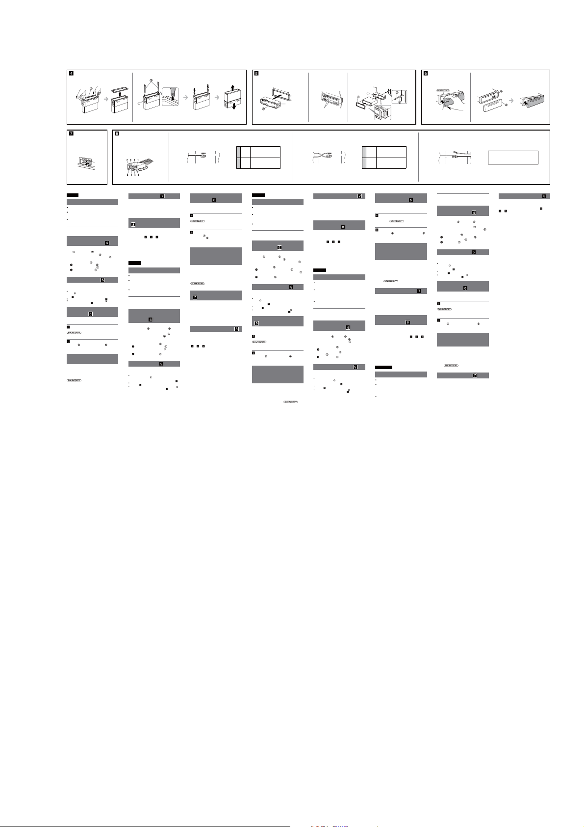
CDX-GT57UPW/GT62UMI/GT570UE/GT570UI/GT570UP/GT574UI/GT620UI/GT626UI
1 2
Fuse (10 A)
Sicherung (10 A)
Fusible (10 A)
Fusibile (10 A)
Zekering (10 A)
English
Precautions
Choose the installation location carefully so that the unit
will not interfere with normal driving operations.
Avoid installing the unit in areas subject to dust, dirt,
excessive vibration, or high temperature, such as in
direct sunlight or near heater ducts.
Use only the supplied mounting hardware for a safe and
secure installation.
Mounting angle adjustment
Adjust the mounting angle to less than 45°.
Removing the protection
collar and the bracket (
Before installing the unit, remove the protection
and the bracket from the unit.
collar
Remove the protection collar .
1
Pinch both edges of the protection collar , then
pull it out.
Remove the bracket .
2
Insert both release keys together between
the unit and the bracket
Pull down the bracket , then pull up the unit
to separate.
Mounting example ( )
Installation in the dashboard
Notes
Before installing, make sure that the catches on both sides of the
are bent inwards 2 mm (3/32 in). If the catches are straight or
bracket
bent outwards, the unit will not be installed securely and may spring
out (
-1).
Bend these claws outward for a tight t, if necessary ( -2).
Make sure that the 4 catches on the protection collar are properly
engaged in the slots of the unit (
How to detach and attach the
front panel (
Before installing the unit, detach the front panel.
-A To detach
Before detaching the front panel, be sure to press and hold
pull it off towards you.
-B To attach
Engage part of the front panel with part of the unit,
as illustrated, and push the le side into position until it
clicks.
Warning if your car’s ignition
has no ACC position
Be sure to set the Auto Off function. For details, see the
supplied Operating Instructions.
e unit will shut off completely and automatically in the
set time aer the unit is turned off, which prevents battery
drain.
If you do not set the Auto Off function, press and hold
you turn the ignition off.
)
until they click.
-3).
)
. Press the front panel release button, and
until the display disappears each time
Face the hook inwards.
Der Haken muss nach innen weisen.
Tournez le crochet vers l’intérieur.
Con il gancetto rivolto verso l’interno.
Het haakje moet naar binnen wijzen.
Auxiliary power connector
Hilfsstromanschluss
Connecteur d’alimentation auxiliaire
Connettore di alimentazione ausiliaria
Hulpvoedingsaansluiting
Fuse replacement ( )
When replacing the fuse, be sure to use one matching the
amperage rating stated on the original fuse. If the fuse
blows, check the power connection and replace the fuse. If
the fuse blows again after replacement, there may be an
internal malfunction. In such a case, consult your nearest
Sony dealer.
Power connection diagram
(
)
Auxiliary power connector may vary depending on the
car. Check your car’s auxiliary power connector diagram
to make sure the connections match correctly. ere are
-1, -2, -3). You may need to
three basic types (
switch the positions of the red and yellow leads in the car
stereo’s power supply lead.
Aer matching the connections and switched power
supply leads correctly, connect the unit to the car’s power
supply. If you have any questions and problems connecting
your unit that are not covered in this manual, please
consult the car dealer.
Deutsch
Sicherheitshinweise
Wählen Sie den Einbauort sorgfältig so aus, dass das
Gerät beim Fahren nicht hinderlich ist.
Bauen Sie das Gerät so ein, dass es keinen hohen
Temperaturen (keinem direkten Sonnenlicht, keiner
Warmlu von der Heizung), keinem Staub, keinem
Schmutz und keinen starken Vibrationen ausgesetzt ist.
Für eine sichere Befestigung verwenden Sie stets die
mitgelieferten Montageteile.
Hinweis zum Montagewinkel
Das Gerät sollte in einem Winkel von weniger als 45°
montiert werden.
Abnehmen der
Schutzumrandung und der
Halterung (
)
Nehmen Sie vor dem Installieren des Geräts die
und die Halterung vom
Schutzumrandung
Gerät ab.
Entfernen Sie die Schutzumrandung .
1
Fassen Sie die Schutzumrandung mit den
Fingern an den Seitenkanten und ziehen Sie sie
heraus.
Entfernen Sie die Halterung .
2
Führen Sie beide Löseschlüssel zwischen
dem Gerät und der Halterung ein, bis sie
mit einem Klicken einrasten.
Ziehen Sie die Halterung nach unten und
das Gerät nach oben, um die beiden zu trennen.
Montagebeispiel ( )
Installation im Armaturenbrett
Hinweise
Vergewissern Sie sich vor dem Installieren, dass die Verriegelungen an
um 2 mm nach innen gebogen sind.
beiden Seiten der Halterung
Wenn die Verriegelungen gerade oder nach außen gebogen sind, lässt
sich das Gerät nicht sicher installieren und kann herausspringen (
Falls erforderlich, biegen Sie diese Klammern für einen sicheren Halt
nach außen (
-2).
Achten Sie darauf, die 4 Verriegelungen an der Schutzumrandung
korrekt in die Aussparungen am Gerät einzusetzen (
-3).
1
182 mm (7 1/4 in)
Catch
Verriegelung
Loquet
Fermo
Greep
Red
Red
1 32
Rot
Rot
Rouge
Rouge
Rosso
Rood
Yellow
Gelb
Jaune
Giallo
Geel
Abnehmen und Anbringen der
Frontplatte (
Nehmen Sie die Frontplatte vor dem Einbau des
Geräts ab.
-A Abnehmen
Halten Sie vor dem Abnehmen der Frontplatte unbedingt
gedrückt. Drücken Sie die Taste zum
Lösen der Frontplatte und ziehen Sie die Frontplatte auf
sich zu und heraus.
-B Anbringen
Setzen Sie Teil der Frontplatte wie in der Abbildung
des Geräts an und drücken Sie die
dargestellt an Teil
linke Seite der Frontplatte an, bis sie mit einem Klicken
einrastet.
Warnhinweis, wenn die
Zündung Ihres Fahrzeugs nicht
über eine Zubehörposition
(ACC oder I) verfügt
Aktivieren Sie unbedingt die Abschaltautomatik. Näheres
dazu nden Sie in der mitgelieferten Bedienungsanleitung.
Nach dem Ausschalten wird das Gerät dann nach der
voreingestellten Zeit automatisch vollständig abgeschaltet,
so dass der Autobatterie kein Strom mehr entzogen wird.
Wenn Sie die Abschaltautomatik nicht aktivieren, müssen
Sie jedes Mal, wenn Sie die Zündung ausschalten, die Taste
gedrückt halten, bis die Anzeige
ausgeblendet wird.
Austauschen der Sicherung
(
)
Wenn Sie eine Sicherung austauschen, achten Sie darauf,
eine Ersatzsicherung mit dem gleichen Ampere-Wert wie
die Originalsicherung zu verwenden. Dieser ist auf der
Originalsicherung angegeben. Wenn die Sicherung
durchbrennt, überprüfen Sie den Stromanschluss und
tauschen die Sicherung aus. Brennt die neue Sicherung
ebenfalls durch, kann eine interne Fehlfunktion vorliegen.
Wenden Sie sich in einem solchen Fall an Ihren
Sony-Händler.
Stromanschlussdiagramm ( )
Der Hilfsstromanschluss kann je nach Fahrzeugtyp
unterschiedlich sein. Sehen Sie im Hilfsstromanschlussdiagramm für Ihr Fahrzeug nach, wie die
Verbindung ordnungsgemäß vorgenommen werden muss.
Es gibt, wie unten abgebildet, drei grundlegende Typen
-1, -2, -3). Sie müssen möglicherweise die rote
(
und gelbe Leitung des Stromversorgungskabels der
Autostereoanlage vertauschen.
Stellen Sie die Anschlüsse her, schließen Sie die
geschalteten Stromversorgungsleitungen richtig an und
verbinden Sie dann das Gerät mit der Stromversorgung
Ihres Fahrzeugs. Wenn beim Anschließen des Geräts
Fragen oder Probleme aureten, die in dieser Anleitung
nicht erläutert werden, wenden Sie sich bitte an den
Autohändler.
-1).
Rosso
Rood
Yellow
Gelb
Jaune
Giallo
Geel
)
continuous power supply
Yellow
Gelb
permanente Stromversorgung
Jaune
alimentation continue
4
Giallo
alimentazione continua
Geel
continue voeding
Red
switched power supply
Rot
geschaltete Stromversorgung
7
alimentation commutée
Rouge
Rosso
alimentazione commutata
Rood
geschakelde voeding
Français
Précautions
Choisir soigneusement l’emplacement de l’installation
afin que l’appareil ne gêne pas la conduite normale du
véhicule.
Eviter d’installer l’appareil dans un endroit exposé à de la
poussière, de la saleté, des vibrations violentes ou à des
températures élevées, comme en plein soleil ou à
proximité d’un conduit de chauage.
Pour garantir un montage sûr, n’utiliser que le matériel
fourni.
Réglage de l’angle de montage
Ajuster l’inclinaison à un angle inférieur à 45°.
Retrait du tour de protection
et du support (
Avant d’installer l’appareil, retirez le tour de
protection
et le support de l’appareil.
Retirez le tour de protection .
1
Saisissez les deux bords du tour de protection ,
puis tirez pour l'extraire.
Retirez le support .
2
Insérez les deux clés de déblocage
simultanément entre l’appareil et le support
jusqu’au déclic indiquant qu’elles sont en place.
Tirez le support vers le bas, puis tirez
l’appareil vers le haut pour les séparer.
Exemple de montage ( )
Installation dans le tableau de bord
Remarques
Avant l’installation, assurez-vous que les loquets des deux côtés du
sont bien pliés de 2 mm vers l’intérieur. Si les loquets sont
support
droits ou pliés vers l’extérieur, l’appareil ne peut pas être xé solidement
et peut se détacher ( -1).
Pliez ces gries vers l’extérieur pour assurer une prise correcte si
-2).
nécessaire (
Assurez-vous que les 4 loquets du tour de protection sont
correctement insérés dans les fentes de l’appareil (
Retrait et xation de la façade
(
)
Avant d’installer l’appareil, retirez la façade.
-A Pour la retirer
Avant de retirer la façade, veillez à appuyer sur la touche
et à la maintenir enfoncée. Appuyez sur
la touche de déverrouillage de la façade et détachez-la en
la tirant vers vous.
-B Pour la xer
Fixez la partie de la façade sur la partie de l’appareil,
comme indiqué sur l’illustration, puis appuyez sur le côté
gauche jusqu’au déclic.
Avertissement au cas où le
contact de votre voiture ne
dispose pas d’une position
ACC
Veillez à régler la fonction de mise hors tension
automatique. Pour obtenir davantage d’informations,
reportez-vous au mode d’emploi fourni.
L’appareil s’éteint complètement et automatiquement après
le laps de temps choisi une fois qu’il a été mis hors tension
afin d’éviter que la batterie ne se décharge.
Si vous ne réglez pas la fonction de mise hors tension
automatique, appuyez sur la touche
maintenez-la enfoncée jusqu’à ce que l’achage
disparaisse à chaque fois que vous coupez le contact.
)
1
/8 in)
53 mm (2
-3).
et
32
Claws
Klammern
Gries
Morsetti
Klemhaken
Red
Red
Rot
Rot
Rouge
Rouge
Rosso
Rosso
Rood
Rood
Yellow
Yellow
Gelb
Gelb
Jaune
Jaune
Giallo
Giallo
Geel
Geel
Remplacement du fusible ( )
Lorsque vous remplacez le fusible, veillez à utiliser un
fusible dont l’intensité, en ampères, correspond à la valeur
indiquée sur le fusible usagé. Si le fusible saute, vériez le
branchement de l’alimentation et remplacez-le. Si le
nouveau fusible saute également, il est possible que
l’appareil soit défectueux. Dans ce cas, consultez votre
revendeur Sony le plus proche.
Schéma de raccordement
d’alimentation (
Le connecteur d’alimentation auxiliaire peut varier suivant
le type de voiture. Vériez le schéma du connecteur
d’alimentation auxiliaire de votre voiture pour vous
assurer que les connexions correspondent. Il en existe trois
types de base (
deviez commuter la position des ls rouge et jaune du
câble d’alimentation de l’autoradio.
Après avoir établi les connexions et commuté
correctement les câbles d’alimentation, raccordez l’appareil
à l’alimentation de la voiture. Si vous avez des questions ou
des dicultés à propos de cet appareil qui ne sont pas
abordées dans le présent mode d’emploi, consultez votre
concessionnaire automobile.
Italiano
Precauzioni
Scegliere con attenzione la posizione per l’installazione
in modo che l’apparecchio non interferisca con le
operazioni di guida del conducente.
Evitare di installare l’apparecchio dove sia soggetto ad
alte temperature, come alla luce solare diretta o al getto
di aria calda dell’impianto di riscaldamento, o dove
possa essere soggetto a polvere, sporco e vibrazioni
eccessive.
Usare solo il materiale di montaggio in dotazione per
un’installazione stabile e sicura.
Regolazione dell’angolo di montaggio
Regolare l’angolo di montaggio in modo che sia inferiore a
45°.
Rimozione della staa e della
cornice protettiva (
Prima di installare l’apparecchio, rimuovere la
cornice protettiva
1
2
Esempio di montaggio ( )
Installazione nel cruscotto
Note
Prima di installare l’unità, accertarsi di ripiegare i fermi presenti su
entrambi i lati della staa
diritti o ripiegati verso l’esterno, l’apparecchio non verrà installato in
modo sicuro e potrebbe fuoriuscire (
Piegare verso l’esterno questi morsetti per un’installazione più sicura, se
necessario (
Assicurarsi che i 4 fermi sulla cornice protettiva siano correttamente
inseriti negli alloggiamenti dell’apparecchio (
)
-1, -2, -3). Il se peut que vous
)
e la staa dall’apparecchio.
Rimuovere la cornice protettiva .
Afferrare la cornice di protezione dai bordi
laterali, quindi estrarla.
Rimuovere la staa .
Inserire contemporaneamente entrambe le
chiavette di rilascio
tra l’apparecchio e la
no a che non scattano in posizione.
staffa
Estrarre la staa , quindi sollevare
l’apparecchio per rimuoverlo.
verso l’interno di 2 mm. Se i fermi sono
-1).
-2).
-3).
Dashboard
Armaturenbrett
Tableau de bord
Cruscotto
Dashboard
Fire wall
Motorraumtrennwand
Paroi ignifuge
Parete tagliaamma
Brandschot
switched power supply
Yellow
Gelb
geschaltete Stromversorgung
Jaune
alimentation commutée
4
Giallo
alimentazione commutata
Geel
geschakelde voeding
Red
continuous power supply
Rot
permanente Stromversorgung
7
alimentation continue
Rouge
Rosso
alimentazione continua
Rood
continue voeding
Come rimuovere e reinserire il
pannello anteriore (
Prima di installare l’apparecchio rimuovere il
pannello anteriore.
-A Per rimuoverlo
Prima di rimuovere il pannello anteriore, assicurarsi di
tenere premuto
pannello anteriore, quindi tirare il pannello verso di sé.
-B Per reinserirlo
Applicare la parte del pannello anteriore alla parte
dell’apparecchio come mostrato nell’illustrazione e
premere il lato sinistro no a sentire uno scatto.
Avvertenza relativa all’installazione
su un’auto sprovvista della
posizione ACC (accessoria) sul
blocchetto di accensione
Accertarsi di impostare la funzione di spegnimento
automatico. Per ulteriori informazioni, fare riferimento
alle istruzioni per l’uso in dotazione.
L’apparecchio si spegne completamente e automaticamente
all’ora impostata dopo che è stato disattivato, onde evitare
che la batteria si scarichi.
Se la funzione di spegnimento automatico non è stata
impostata, ogni volta che il motore viene spento tenere
premuto
disattivato.
Sostituzione del fusibile ( )
Per la sostituzione del fusibile, assicurarsi di utilizzare un
fusibile dello stesso amperaggio di quello indicato
sull’originale. Se il fusibile si brucia, controllare i
collegamenti dell’alimentazione e sostituire il fusibile. Se
dopo la sostituzione il fusibile si brucia di nuovo, è
possibile che si tratti di un problema interno. In tal caso,
rivolgersi al più vicino rivenditore Sony.
Diagramma dei collegamenti
di alimentazione (
Il connettore di alimentazione ausiliaria può variare a
seconda della macchina. Controllare il diagramma del
connettore di alimentazione ausiliaria della macchina per
essere sicuri che i collegamenti corrispondano
correttamente. Vi sono tre tipi di base (
Potrebbe essere necessario cambiare le posizioni dei li
rosso e giallo nel cavo di alimentazione dello stereo della
macchina.
Dopo aver fatto corrispondere i collegamenti e aver
commutato i cavi di alimentazione, collegare l’apparecchio
all’alimentazione della macchina. Se si hanno domande o
se sorgono problemi che non sono stati trattati nel
manuale nel collegare l’apparecchio, contattare
l’autoconcessionario.
Nederlands
Voorzorgsmaatregelen
Kies de installatieplaats zorgvuldig zodat het apparaat de
bestuurder niet hindert tijdens het rijden.
Installeer het apparaat niet op plaatsen waar het
blootgesteld wordt aan hoge temperaturen, bv. in direct
zonlicht of bij de warme luchtstroom van de
autoverwarming, aan sterke trillingen, of waar het in
contact komt met veel stof of vuil.
Gebruik voor het veilig en stevig monteren van het
apparaat uitsluitend de bijgeleverde montageonderdelen.
)
. Premere il tasto rilascio
nché il display non viene
)
-1, -2, -3).
A B
Front panel release button
Taste zum Lösen der Frontplatte
Touche de déverrouillage de la façade
Tasto rilascio pannello anteriore
Toets om het voorpaneel los te maken
Red
Red
Rot
Rot
Rouge
Rouge
Rosso
Rosso
Rood
Rood
Yellow
Yellow
Gelb
Gelb
Jaune
Jaune
Giallo
Giallo
Geel
Geel
Maximale montagehoek
Installeer het apparaat nooit in een hoek van meer dan 45°
met het horizontale vlak.
De beschermende rand en de
beugel verwijderen (
Voordat u het apparaat gaat installeren, moet u de
en de beugel verwijderen
beschermende rand
van het apparaat.
Verwijder de beschermende rand .
1
Druk beide zijden van de beschermende rand in
en trek de rand naar u toe.
Verwijder de beugel .
2
Plaats de ontgrendelingssleutels tussen het
tot deze vastklikken.
apparaat en de beugel
Trek de beugel omlaag en trek het apparaat
omhoog om deze van elkaar te scheiden.
Montagevoorbeeld ( )
Montage in het dashboard
Opmerkingen
Voordat u het apparaat installeert, moet u de grepen aan beide zijden
2 mm naar binnen buigen. Als de grepen recht zijn of
van de beugel
naar buiten gebogen, kan het apparaat niet goed worden bevestigd en
kan dit losschieten (
-1).
Indien nodig kunt u deze klemhaken ombuigen voor een stevigere
-2).
bevestiging (
De 4 grepen op de beschermende rand moeten goed in de sleuven
van het apparaat zijn geplaatst (
-3).
Het voorpaneel verwijderen
en bevestigen (
Verwijder, alvorens met het installeren te beginnen,
het afneembare voorpaneel.
Voordat u het voorpaneel verwijdert, moet u
het voorpaneel los te maken en trek het voorpaneel naar u
toe.
Breng deel van het voorpaneel aan op deel van het
apparaat zoals afgebeeld en druk op de linkerzijde tot deze
vastklikt.
Zorg ervoor dat u de functie voor automatisch
uitschakelen instelt. Raadpleeg de bijgeleverde
gebruiksaanwijzing voor meer informatie.
Het apparaat wordt na de ingestelde tijd automatisch
volledig uitgeschakeld nadat het apparaat is uitgeschakeld.
Zo wordt voorkomen dat de accu leegloopt.
Als u de functie voor automatisch uitschakelen niet instelt,
moet u
verdwijnt telkens wanneer u het contact uitschakelt.
Vervang een zekering altijd door een exemplaar van
eenzelfde ampèrage als op de oorspronkelijke zekering
wordt vermeld. Als de zekering doorbrandt, moet u de
voedingsaansluiting controleren en de zekering vervangen.
Brandt de zekering vervolgens nogmaals door, dan kan er
sprake zijn van een defect in het apparaat. Raadpleeg in
dat geval de Sony-dealer bij u in de buurt.
)
-A Verwijderen
ingedrukt houden. Druk op de toets om
-B Bevestigen
Waarschuwing als het
contactslot van de auto geen
ACC-positie heeft
ingedrukt houden tot het display
Zekering vervangen ( )
)
the car without ACC position
Fahrzeug ohne Zubehörposition (ACC oder I)
Véhicule sans position ACC
Auto priva della posizione ACC
Auto zonder ACC-positie
Voedingsaansluitschema ( )
De hulpvoedingsaansluiting kan verschillen afhankelijk
van de auto. Controleer het hulpvoedingsaansluitschema
dat bij dit apparaat wordt geleverd om te zien of de
aansluitingen kloppen. Er zijn drie basistypes (
-2, -3). Het is mogelijk dat u de posities van de rode
en gele kabels in de voedingskabel van het
autoaudiosysteem moet omwisselen.
Als de aansluitingen en geschakelde voedingskabels
kloppen, sluit u het apparaat aan op de voeding van de
auto. Indien u nog vragen of problemen hebt in verband
met het aansluiten van het apparaat die niet in deze
handleiding worden behandeld, raadpleeg dan de
autodealer.
-1,
11
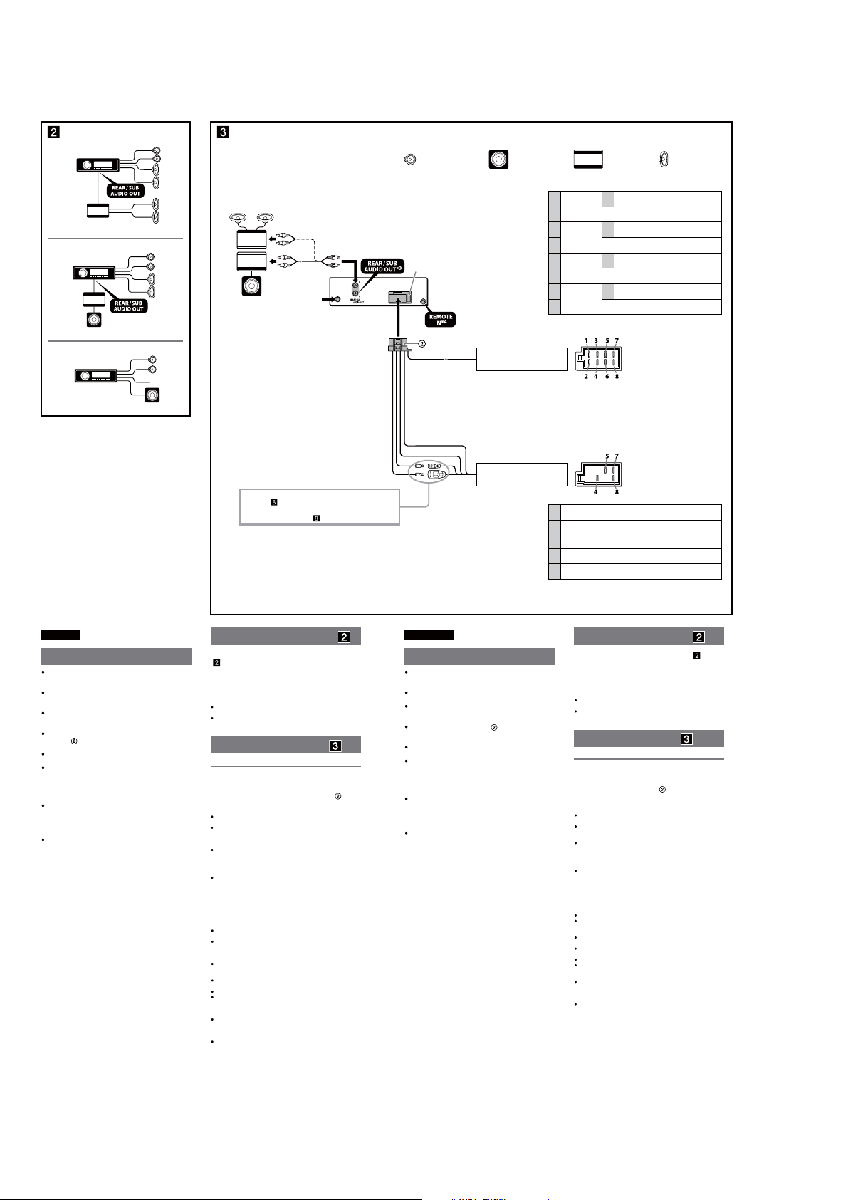
CDX-GT57UPW/GT62UMI/GT570UE/GT570UI/GT570UP/GT574UI/GT620UI/GT626UI
(CDX-GT570UE/GT570UI: Russian /GT574UI: Russian model)
Оборудование, фигурирующее в иллюстрациях (не входит в комплект)
A
B
2
*
1
от автомобильной
*
антенны
від автомобільної
радіоантени
C
*
Обладнання, зображене на малюнках (не надається в комплекті)
Передний громкоговоритель
Передній динамік
Предохранитель (10 А)
Запобіжник (10 A)
*
5
от разъема громкоговорителей
автомобиля
від роз’єму динаміка автомобіля
Сабвуфер
Низькочастотний динамік
1
Фиолетовый
Фіолетовий
2–
3
Серый
Сірий
4–
5
Белый
Білий
6–
7
Зеленый
Зелений
8–
Позиции отрицательной полярности 2, 4, 6 и 8 имеют провода с полосками.
Проводка до позицій із від’ємною полярністю 2, 4, 6 і 8 – смугаста.
Усилитель мощности
Підсилювач потужності
Громкоговоритель, задний, правый
+
Динамік: задній, правий
Громкоговоритель, задний, правый
Динамік: задній, правий
Громкоговоритель, передний, правый
+
Динамік: передній, правий
Громкоговоритель, передний, правый
Динамік: передній, правий
Громкоговоритель, передний, левый
+
Динамік: передній, лівий
Громкоговоритель, передний, левый
Динамік: передній, лівий
Громкоговоритель, задний, левый
+
Динамік: задній, лівий
Громкоговоритель, задний, левый
Динамік: задній, лівий
Задний громкоговоритель
Задній динамік
Pyccкий
Внимание
Данный аппарат предназначен для подключения
только к аккумулятору 12 В постоянного тока с
отpицaтeльным заземлением.
He допycкaйтe попaдaния пpоводов под винты или
мeждy подвижными дeтaлями (нaпpимep, мeждy
нaпpaвляющими cидeний).
Пepeд выполнeниeм cоeдинeния выключитe
зaжигaниe aвтомобиля во избeжaниe коpоткого
зaмыкaния.
Сначала подсоедините соединительный кабель
к аппарату и громкоговорит елям, а
питания
затем к контактам внешнего источника питания.
Подведите все провода заземления к одной
точке заземления.
B цeляx бeзопacноcти обязaтeльно изолиpyйтe вce
cвободныe нeподcоeдинeнныe пpоводa
изоляционной лeнтой.
Пpимeчaния отноcитeльно провода питания
(жeлтого)
Пpи подключeнии этого аппарата вмecтe c дpyгими
cтepeокомпонeнтaми номинaльноe знaчeниe cилы
токa в контype питaния aвтомобиля должно
пpeвышaть cyммapноe знaчeниe cилы токa,
yкaзaнноe нa пpeдоxpaнитeляx вcex компонeнтов.
Ecли номинaльноe знaчeниe cилы токa в контype
питaния aвтомобиля недостаточно выcокоe,
подcоeдинитe аппарат нaпpямyю к aккyмyлятоpy.
Подpобнee cм. в paздeлe “Cxeмa подключeния
)” нa обpaтной cтоpонe.
питaния (
Для отримання детальної інформації див. «Схема
підключення живлення (
*1 В зависимости от типа автомобиля используйте адаптер
(приобретается отдельно), если разъем антенны не
подходит.
2
*
Кабель с разъемами RCA (не входит в комплект)
3
Для AUDIO OUT можно выбpaть положeниe SUB или REAR. Для
*
полyчeния дополнитeльной инфоpмaции cм. пpилaгaeмыe
инcтpyкции по экcплyaтaции.
4
*
Может потребоваться отдельный адаптер.
*5 Полное сопротивление громкоговорителей: 4–8 Ом × 4
)» на зворотній стороні.
Пример подсоединения ( )
Непосредственное соединение с сабвуфером
-C)
(
Для получения подробных сведений о выполнении
подключения см. прилагаемую инструкцию по
эксплуатации.
* Не подк лючайте громкоговоритель к этому разъему.
Примечания
Прежде чем подключать аппарат к усилителю, обязательно
подсоедините провод заземления.
Звуковой сигнал будет воспроизводиться только в том случае,
если используется встроенный усилитель.
Схема подсоединения ( )
Предостережение
Если используется антенна с электрическим приводом
без релейного блока, подсоединение этого аппарата
посредством прилагаемого провода питания
привести к повреждению антенны.
О проводах управления и питания
При включении устройства через провод REM OUT (в сине-белую
полоску) поступает постоянный ток напряжением +12 В.
При использовании дополнительного усилителя мощности
подключите провод REM OUT (в сине-белую полоску) или
дополнительный провод питания (красный) к разъему AMP
REMOTE IN.
Если машина оснащена радиоантенной FM/MW/LW, встроенной
в заднее или боковое стекло, подсоедините провод REM OUT (в
сине-белую полоску) или дополнительный провод питания
(красный) к разъему питания усилителя антенны. Для получения
подробных сведений обратитесь к своему продавцу.
Антенна с электрическим приводом, не снабженная релейным
блоком, с этим аппаратом использоваться не может.
Подсоединение для поддержки памяти
Когда к аппарату подсоединен желтый электрический провод,
блок памяти будет постоянно получать питание даже при
выключенном зажигании.
Примечания относительно подсоединения
громкоговорителей
Прежде чем подсоединять громкоговорители, выключите
аппарат.
Используйте громкоговорители с полным сопротивлением
4 - 8 Ом, обладающие способностью принимать достаточно
мощный сигнал. В противном случае они могут быть
повреждены.
Не подсоединяйте контактные гнезда громкоговорителей к
шасси автомобиля и не соединяйте гнезда правого
громкоговорителя с гнездами левого.
He подключaйтe пpовод зaзeмлeния аппарата к
отpицaтeльномy (–) контaктy гpомкоговоpитeля.
Не пытайтесь подсоединить громкоговорители параллельно.
Подсоединять можно только пассивные громкоговорители.
Подсоединение активных громкоговорителей (со встроенным
усилителем) к гнездам для громкоговорителей может привести
к повреждению аппарата.
Bо избeжaниe нeпpaвильной paботы аппарата нe иcпользyйтe
вcтpоeнныe в aвтомобиль пpоводa гpомкоговоpитeлeй, ecли
используется общий отpицaтeльный пpовод (–) для пpaвого и
лeвого гpомкоговоpитeлeй.
He подсоединяйте друг к другу пpоводa гpомокоговоpитeлeй
аппарата.
Пpимeчaниe отноcитeльно подcоeдинeния
Ecли гpомкоговоpитeль и ycилитeль подcоeдинeны нeпpaвильно,
нa диcплee отобpaзитcя нaдпиcь “FAILURE”. B этом cлyчae
пpовepьтe пpaвильноcть подcоeдинeния гpомкоговоpитeля и
ycилитeля.
может
от разъема электропитания
автомобиля
від роз’єму живлення автомобіля
1
*
Використовуйте адаптер (не входить до комплекту
постачання), якщо роз’єм антени не підходить - це залежить
від автомобіля.
2
*
Шнур RCA з контактними штирками (не надається в
комплекті)
3
*
AUDIO OUT можна переключити на SUB або REAR. Для
отримання докладнішої інформації див. інструкцію з
експлуатації.
4
*
Може знадобитися окремий адаптер.
5
Повний опір динаміків: 4–8 Ом × 4
*
Укpaїнcькa
Увага!
Цей пристрій розроблено лише для роботи із
джерелом постійної напруги 12 В із заземленням
від’ємного полюса.
Запобігайте попаданню проводки під гвинти або
між рухомих деталей (наприклад, поруччя сидіння).
Перед створенням підключень вимкніть
запалювання автомобіля, щоб запобігти коро ткому
замиканню.
Підключіть кабель живлення до пристрою та
динаміків перед його підключенням до додаткового
роз’єму живлення.
Підключіть всі заземлені кабелі до однієї точки
заземлення.
Переконайтеся в тому, що будь-які вільні
непідключені кабелі ізольовано відповідною
ізолюючою стрічкою для забезпечення безпеки.
Примітки щодо кабелю підключення живлення
(жовтий)
За підключення пристрою разом з іншими
стереокомпонентами сила струму в контурі
автомобіля має бути вищою суми значень сили
струму, вказаної на плавких запобіжниках кожного
компонента.
Якщо сила струму в контурі автомобіля недос татньо
висока, підключіть пристрій безпосередньо до
акумулятора.
Желтый
4
Жовтий
С сине-белыми
полосками
5
У синьо-білу
смужку
Красный
7
Червоний
Черный
8
Чорний
Позиции 1, 2, 3 и 6 не имеют контактных штырьков.
Позиції 1, 2, 3 та 6 не мають контактних штирків.
непрерывное поступление питания
неперервне постачання живлення
управление антенной или усилителем
мощности (REM OUT)
керування антеною або підсилювачем
(REM OUT)
импульсный источник питания
імпульсне постачання живлення
земля
заземлення
Приклад підключення ( )
Безпосереднє підключення сабвуфера ( -C)
Для отримання докладніших відомостей див.
інструкцію з експлуатації, що входить до комплекту
постачання.
* Не підк лючайте динамік до цього роз’єму.
Примітка
Перед підключенням підсилювача переконайтеся, що підключено
заземлений кабель.
Сигнал сповіщення спрацює, лише якщо використовується
вбудований підсилювач.
Схема підключення ( )
Увага!
Якщо антена з електроприводом не має релейної
стійки, підключення цього пристрою за допомогою
кабелю живлення з комплекту
антену.
Примітка щодо кабелю керування та кабелю постачання
живлення
Через провід REM OUT (у синьо-білу смугу) подається постійний
струм +12 В під час ввімкнення пристрою.
У разі використання підсилювача під’єднайте провід REM OUT (у
синьо-білу смугу) або додатковий шнур живлення (червоний) до
роз’єму AMP REMOTE IN.
Якщо машину обладнано радіоантеною FM/MW/LW, вбудованою
в заднє або бокове скло, підключіть провід REM OUT (у синьо-білу
смугу) або додатковий шнур живлення (червоний) до роз’єму
живлення антенного підсилювача. Для отримання докладніших
відомостей зверніться до свого продавця.
Антену з електроприводом без релейної стійки не можна
використовувати з цим пристроєм.
Підключення запам’ятовувальної системи
Якщо підключено жовтий кабель постачання живлення, живлення
завжди постачатиметься до запам’ятовувальної схеми навіть за
вимкненого запалення.
Примітка щодо підключення динаміка
Перед підключенням динаміків вимкніть пристрій.
Використовуйте динаміки з повним опором від 4 до 8 Ом і з
відповідною припустимою вхідною потужністю, щоб уникнути
їх пошкодження.
Не підключайте роз’єми динаміків до корпусу автомобіля і не
з’єднуйте роз’єми правого і лівого динаміків.
Не підключайте заземлений кабель цього пристрою до
від’ємного (–) роз’єму динаміка.
Не намагайтеся підключити динаміки паралельно.
Підключайте лише пасивні динаміки. Підключення активних
динаміків (із вбудованим підсилювачем) до роз’ємів динаміків
може пошкодити пристрій.
Щоб уникнути несправної роботи пристрою, не
використовуйте вбудований кабель динаміка, встановлений в
автомобілі, якщо пристрій використовує спільний негативний
(–) кабель для правого та лівого динаміків.
Не підключайте кабелі динаміків пристрою один до одного.
Примітка щодо підключення
Якщо динамік і підсилювач не підключено належним чином, на
дисплеї відобразиться «FAILURE» (помилка). У такому випадку
переконайтеся, що динамік і підсилювач підключено належним
чином.
може пошкодити
12
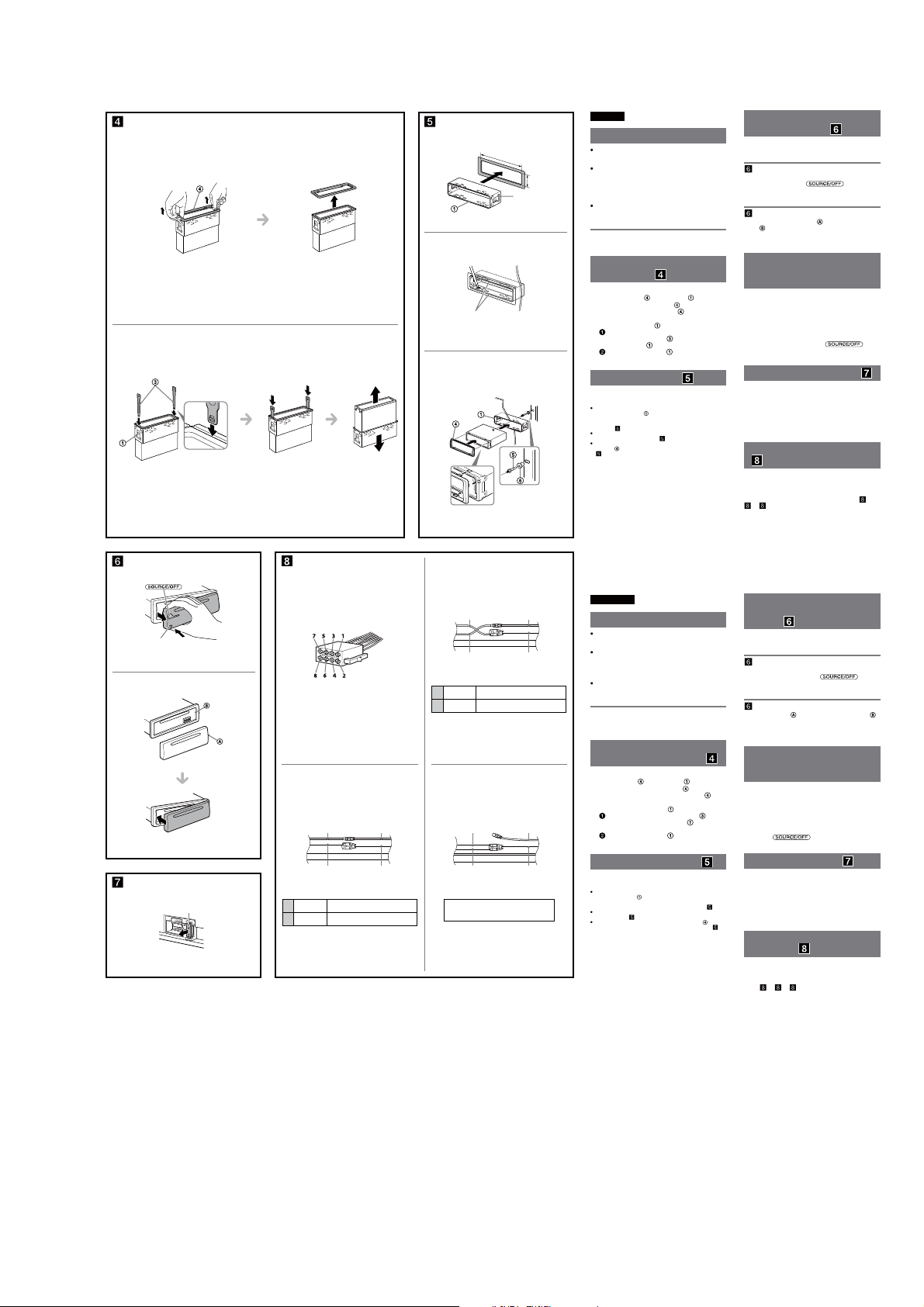
CDX-GT57UPW/GT62UMI/GT570UE/GT570UI/GT570UP/GT574UI/GT620UI/GT626UI
1
2
A
Кнопка снятия передней
панели
Кнопка розблокування
передньої панелі
B
Haпpaвьтe кpючок внyтpь.
Гачком усередину.
Предохранитель (10 А)
Запобіжник (10 A)
1
182 mm
Фикcaтоp
Фіксатор
53 mm
2
Bыcтyпы
Фіксатори
3
Огнеупорная
перегородка
Приборная пaнeль
Панель приладів
Вогнетривке
загородження
2
Дополнительный разъем питания
Додатковий роз’єм живлення
Красный
Червоний
Желтый
Жовтий
Желтый
4
Жовтий
Красный
7
Червоний
Красный
Червоний
Желтый
Жовтий
импульсный источник питания
імпульсне постачання живлення
непрерывное поступление питания
неперервне постачання живлення
13
Красный
Червоний
Желтый
Жовтий
Желтый
4
Жовтий
Красный
7
Червоний
Красный
Червоний
Желтый
Жовтий
непрерывное поступление питания
неперервне постачання живлення
импульсный источник питания
імпульсне постачання живлення
Красный
Червоний
Желтый
Жовтий
автомобиль не имеет положения АСС
автомобіль не має положення ACC
Красный
Червоний
Желтый
Жовтий
Pyccкий
Меры предосторожности
Место для установки аппарата выбирайте
тщательно, чтобы он не мешал управлению
автомобилем.
Не устанавливайте аппарат там, где он будет
подвержен воздействию пыли, грязи, чрезмерной
вибрации или высоких температур, например в
местах, попадающих под прямые солнечные лучи
или находящихся вблизи вентиляционных решеток
обогревателей.
В целях обеспечения надежной и безопасной
установки используйте лишь входящие в комплект
монтажные детали.
Допустимый угол установки
Установите аппарат под углом не более 45°.
Cнятиe зaщитной мaнжeты и
кpонштeйнa (
Пepeд ycтaновкой аппарата снимите с него
зaщитнyю мaнжeтy
Cнятиe зaщитной мaнжeты .
1
Снимите защитную манжету , зацепив ее за
края.
Cнятиe кpонштeйнa .
2
Bcтaвьтe одновpeмeнно до щeлчкa обa
ключa для дeмонтaжa
кpонштeйном
Потянитe кpонштeйн вниз, a аппарат
- ввepx, чтобы отдeлить одно от дpyгого.
)
и кpонштeйн .
мeждy аппаратом и
.
Пpимep ycтaновки ( )
Установка аппарата в приборной пaнeли
Пpимeчaния
Пepeд ycтaновкой yбeдитecь, что фикcaтоpы по обeим
cтоpонaм кpонштeйнa
фикcaтоpы нaxодятcя в пpямом положeнии или выгнyты
наружу, аппарат не удастся надежно установить, и он может
выпасть (
Пpи нeобxодимоcти отогнитe эти выcтyпы нapyжy, чтобы
обecпeчить плотнyю подгонкy (
Убeдитecь, что 4 фикcaтоpa, имeющиecя нa зaщитной
мaнжeтe , нaдeжно вcтaвлeны в отвepcтия нa аппарате
( -3).
-1).
зaгнyты внyтpь нa 2 мм. Ecли
-2).
Укpaїнcькa
Заходи безпеки
Уважно виберіть місце для встановлення, щоб
пристрій не перешкоджав нормальному керуванню
автомобілем.
Уникайте встановлення пристрою у місцях, що
піддаються впливу пилу, бруду, надмірної вібрації
або високої температури, наприклад, у місцях, на які
падає пряме сонячне проміння, або біля
вентиляційних отворів обігрівача.
Для безпечного та надійного встановлення
використовуйте монтажне обладнання тільки з
комплекту поставки.
Регулювання кута встановлення
Відрегулюйте кут встановлення так, щоб він був не
більше 45°.
Від’єднання захисної
манжети та кронштейна (
Перед встановленням апарата від’єднайте
захисну манжету
1
2
та кронштейн від апарата.
Від’єднання захисної манжети .
Захопіть обидва краї захисної манжети , а
потім витягніть її.
Від’єднання кронштейна .
Вставте обидва демонтажні ключі разом
між апаратом і кронштейном
пролунає клацання.
Потягніть кронштейн донизу, а потім
потягніть виріб догори, щоб роз’єднати їх.
, доки не
Приклад встановлення ( )
Встановлення в панелі приладів
Примітка
Перед встановленням переконайтеся, що фіксатори з обох
сторін кронштейна зігнуто всередину на 2 мм. Якщо
фіксатори не зігнуто або вони знаходяться зовні, пристрій не
буде встановлено належним чином і він може випасти ( -1).
Якщо потрібно, вигніть ці виступи назовні, щоб забезпечити
-2).
щільну фіксацію (
Переконайтеся, що 4 фіксатори на захисній манжеті
належним чином встановлені в отвори, наявні в апараті (
Порядок снятия и установки
передней панели (
Перед установкой аппарата снимите с него
переднюю панель.
-A Снятие панели
Прежде чем снимать переднюю панель, обязательно
нажмите и удерживайте
кнопку снятия передней панели, затем снимите
панель, потянув ее на себя.
-B Установка панели
Сначала присоедините часть передней панели к
аппарата, как это показано на иллюстрации,
части
а затем вдвиньте в паз левую часть панели до легкого
щелчка.
Внимание. Если в замке
зажигания нет положения
ACC
Задайте функцию автоматического выключения. Для
получения дополнительной информации см.
прилагаемые инструкции по эксплуатации.
После выключения аппарата его питание будет
автоматически отключено в установленное время, что
предотвращает разрядку аккумулятора.
Если функция автоматического выключения не
задана, то при каждом выключении зажигания
нажмите и удерживайте кнопку
пор, пока дисплей не погаснет.
Замена предохранителя ( )
При замене предохранителей обязательно используйте
только те, которые соответствуют силе тока,
указанной на оригинальном предохранителе. Если
перегорел предохранитель, проверьте подключение
питания и замените предохранитель. Если после
замены предохранитель снова перегорел, это может
означать неисправность устройства. В этом случае
обратитесь к ближайшему дилеру Sony.
Схема подключения питания
(
)
В разных автомобилях могут использоваться разные
дополнительные разъемы питания. Чтобы убедиться в
правильности подсоединения, обpaтитecь к cxeмe
подключения дополнительного разъема питания
Вашего автомобиля. Есть три основных типа (
-2, -3). Возможно, придется поменять местами
подключение красного и желтого проводов в
соединительном кабеле питания стереосистемы.
После проверки пpaвильноcти подключeния в
paзъeмax подключите аппарат к электропитанию
автомобиля. Если возникли какие-либо вопросы или
проблемы, связанные с подключением аппарата,
которые не рассматриваются в настоящем
руководстве, обратитесь за советом к дилеру
автомобильной фирмы.
Порядок від’єднання і
приєднання передньої
панелі (
)
Перед встановленням апарата від’єднайте
передню панель.
-A Для від’єднання
Перш ніж від’єднати передню панель, обов’язково
натисніть і утримуйте кнопку
Натисніть кнопку розблокування передньої панелі та
потягніть панель до себе.
-B Для приєднання
З’єднайте частину передньої панелі з частиною
пристрою, як показано на ілюстрації, і натискайте на
ліву сторону, доки панель, клацнувши, не стане на
місце.
Увага. Якщо у замку
)
запалювання автомобіля
немає положення ACC
Обов’язково налаштуйте функцію автоматичного
вимкнення. Для отримання детальної інформації див.
інструкції з експлуатації, які постачаються в
комплекті. Після вимкнення пристрою він
автоматично вимкне живлення у встановлений час,
що запобігає витраті заряду акумулятора. Якщо
функцію автоматичного вимкнення не встановлено,
після кожного вимикання запалювання натискайте та
утримуйте
зображення на дисплеї.
, доки не зникне
Заміна запобіжника ( )
Замінюючи запобіжник, переконайтеся, що новий
запобіжник розрахований на таку саму силу ст руму,
як і оригінальний. Якщо запобіжник перегорає,
перевірте підключення живлення та замініть
запобіжник. Якщо запобіжник перегорає знову після
заміни, причиною цього може бути внутрішня
неполадка. У такому разі зверніться до найближчого
дилера Sony.
-3).
Схема підключення
живлення (
Допоміжний роз’єм живлення може різнитися
залежно від автомобіля. Перевірте схему допоміжного
роз’єму живлення у своєму автомобілі, щоб
впевнитися у правильності з’єднань. Існує три основні
типи (
місцями положення червоного і жовтого дротів у
кабелі живлення автомобільної стереосистеми.
Перевіривши правильність підключення в роз’ємах,
підключіть пристрій до електроживлення автомобіля.
Якщо виникли запитання або проблеми з пристроєм,
не описані в цій інструкції, зверніться за допомогою
до дилера автомобільної компанії.
)
-1, -2, -3). Може знадобитися поміняти
)
. Нажмите
до тех
-1,
.
13
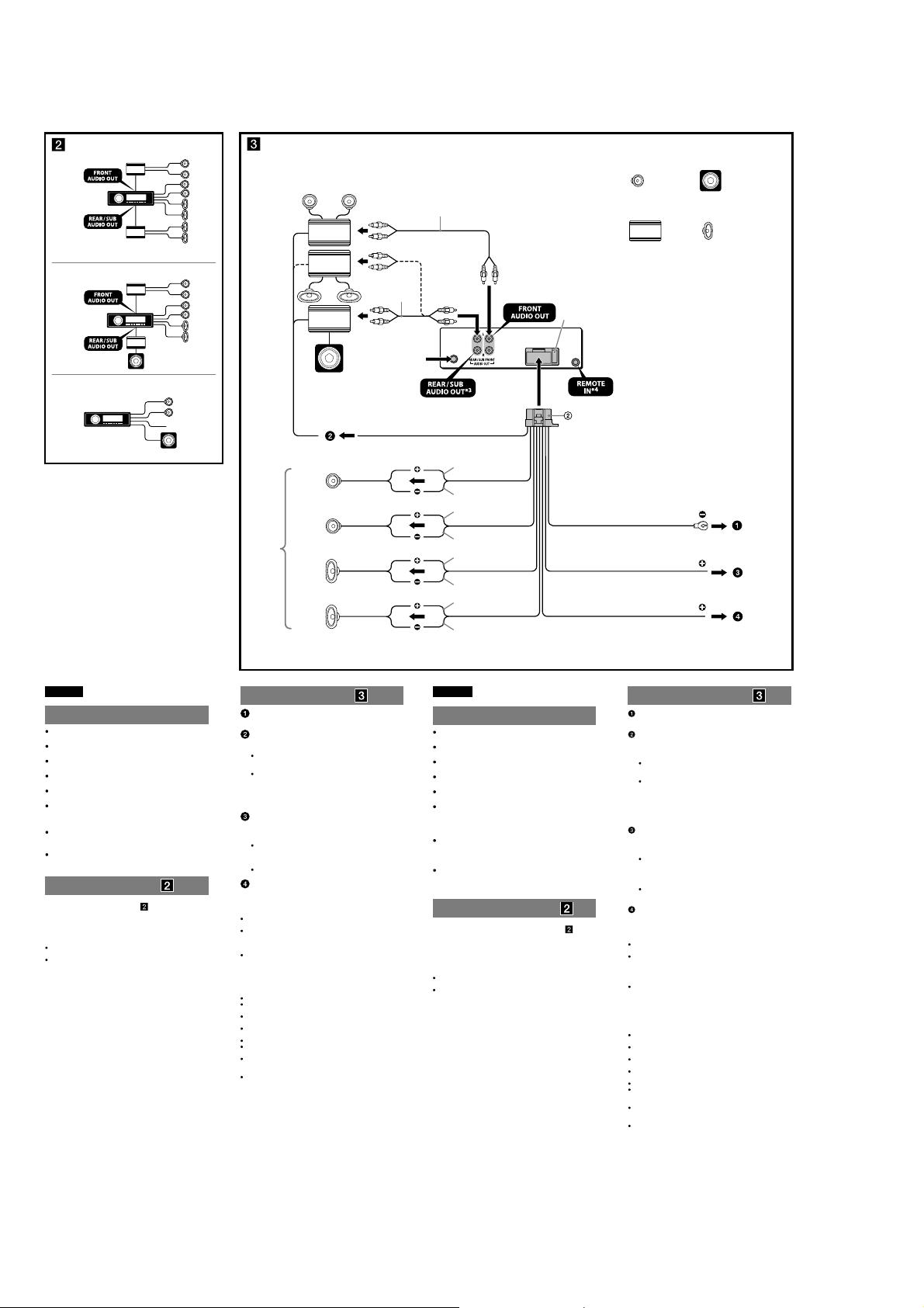
CDX-GT57UPW/GT62UMI/GT570UE/GT570UI/GT570UP/GT574UI/GT620UI/GT626UI
Ver. 1.1
(CDX-GT62UMI/GT620UI: Mexican /GT626UI)
Equipment used in illustrations (not supplied)
A
Equipo utilizado en las ilustraciones (no
suministrado)
Front speaker
2
*
Altavoz frontal
Power amplier
Amplicador de potencia
Subwoofer
Altavoz potenciador de graves
Rear speaker
Altavoz posterior
B
2
*
from car antenna (aerial)
desde la antena del
automóvil
C
*
Left
Izquierdo
Right
Derecho
1
*
Left
Izquierdo
Right
Derecho
REM OUT
Max. supply current 0.4 A
Corriente máx. de alimentación de 0,4 A
Blue/white striped
Con rayas azules y blancas
White
Blanco
White/black striped
Con rayas blancas y negras
Gray
Gris
Gray/black striped
Con rayas grises y negras
Green
Verde
Green/black striped
Con rayas verdes y negras
Purple
Morado
Purple/black striped
Con rayas moradas y negras
Fuse (10 A)
Fusible (10 A)
Black
Negro
Red
Rojo
Yellow
Amarillo
1
Speaker impedance: 4 – 8 ohms × 4
*
2
RCA pin cord (not supplied).
*
3
AUDIO OUT can be switched SUB or REAR. For details, see the
*
supplied Operating Instructions.
4
*
Separate adaptor may be required.
1
*
Impedancia de los altavoces: de 4 a 8 Ω × 4
2
Cable con terminales RCA (no suministrado).
*
3
*
AUDIO OUT (salida de audio) puede cambiarse a SUB o REAR.
Para obtener información, consulte el manual de instrucciones
suministrado.
4
*
Puede requerirse un adaptador independiente.
ACC
BATTERY
English
Cautions
is unit is designed for negative ground (earth) 12 V
DC operation only.
Do not get the leads under a screw, or caught in moving
parts (e.g. seat railing).
Before making connections, turn the car ignition off to
avoid short circuits.
Connect the yellow and red power input leads only
after all other leads have been connected.
Run all ground (earth) leads to a common ground
(earth) point.
Be sure to insulate any loose unconnected leads with
electrical tape for safety.
Notes on the power supply lead (yellow)
When connecting this unit in combination with other
stereo components, the connected car circuit’s rating
must be higher than the sum of each component’s fuse.
When no car circuits are rated high enough, connect the
unit directly to the battery.
Connection example ( )
Subwoofer Direct Connection ( -C)
For details on the setting for the connection, see the
supplied Operating Instruction.
* Do not connect a speaker in this connection.
Notes
Be sure to connect the ground (earth) lead before connecting the
amplier.
The alarm will only sound if the built-in amplier is used.
Connection diagram ( )
To a metal surface of the car
First connect the black ground (earth) lead, then connect the yellow,
and red power supply leads.
To the power antenna (aerial) control lead or
power supply lead of antenna (aerial) booster
Notes
It is not necessary to connect this lead if there is no power antenna
(aerial) or antenna (aerial) booster, or with a manually-operated
telescopic antenna (aerial).
When your car has a built-in FM/AM antenna (aerial) in the rear/
side glass, see “Notes on the control and power supply leads.”
To AMP REMOTE IN of an optional power
amplier
This connection is only for ampliers and a power antenna (aerial).
Connecting any other system may damage the unit.
To the +12 V power terminal which is energized
in the accessory position of the ignition key
switch
Notes
If there is no accessory position, connect to the +12 V power
(battery) terminal which is energized at all times.
Be sure to connect the black ground (earth) lead to a metal surface
of the car rst.
When your car has a built-in FM/AM antenna (aerial) in the rear/
side glass, see “Notes on the control and power supply leads.”
To the +12 V power terminal which is energized
at all times
Be sure to connect the black ground (earth) lead to a metal surface of
the car rst.
Notes on the control and power supply leads
REM OUT lead (blue/white striped) supplies +12 V DC when you turn on
the unit.
When your car has built-in FM/AM antenna (aerial) in the rear/side
glass, connect REM OUT lead (blue/white striped) or the accessory
power supply lead (red) to the power terminal of the existing antenna
(aerial) booster. For details, consult your dealer.
A power antenna (aerial) without a relay box cannot be used with this
unit.
Memory hold connection
When the yellow power input lead is connected, power will always be
supplied to the memory circuit even when the ignition switch is turned o.
Notes on speaker connection
Before connecting the speakers, turn the unit o.
Use speakers with an impedance of 4 to 8 ohms, and with adequate
power handling capacities to avoid its damage.
Do not connect the speaker terminals to the car chassis, or connect the
terminals of the right speakers with those of the left speaker.
Do not connect the ground (earth) lead of this unit to the negative (–)
terminal of the speaker.
Do not attempt to connect the speakers in parallel.
Connect only passive speakers. Connecting active speakers (with
built-in ampliers) to the speaker terminals may damage the unit.
To avoid a malfunction, do not use the built-in speaker leads installed in
your car if the unit shares a common negative (–) lead for the right and
left speakers.
Do not connect the unit’s speaker leads to each other.
Note on connection
If speaker and amplier are not connected correctly, “FAILURE” appears in
the display. In this case, make sure the speaker and amplier are
connected correctly.
Español
Precauciones
Esta unidad ha sido diseñada para alimentarse sólo con
cc de 12 V de masa negativa.
No coloque los cables debajo de ningún tornillo, ni los
aprisione con partes móviles (p. ej. los rieles del asiento).
Antes de realizar las conexiones, apague el automóvil
para evitar cortocircuitos.
Conecte los cables de fuente de alimentación amarillo y
rojo solamente después de haber conectado los demás.
Conecte todos los cables de conexión a masa a un
punto común.
Por razones de seguridad, asegúrese de aislar con cinta
aislante los cables sueltos que no estén conectados.
Notas sobre el cable de fuente de alimentación
(amarillo)
Cuando conecte esta unidad en combinación con otros
componentes estéreo, la capacidad nominal del circuito
conectado del automóvil debe ser superior a la suma del
fusible de cada componente.
Si no hay circuitos del automóvil con capacidad nominal
suficientemente alta, conecte la unidad directamente a la
batería.
Ejemplo de conexiones ( )
Conexión directa de altavoz de subgraves ( -C)
Para obtener más información sobre cómo configurar la
conexión, consulte el Manual de instrucciones
suministrado.
* No conecte un altavoz a esta conexión.
Notas
Asegúrese de conectar primero el cable de conexión a masa antes de
realizar la conexión del amplicador.
La alarma sonará únicamente si se utiliza el amplicador incorporado.
Diagrama de conexión ( )
A una supercie metálica del automóvil
Conecte primero el cable de conexión a masa negro, y después los
cables amarillo y rojo de fuente de alimentación.
Al cable de control de la antena motorizada o al
cable de fuente de alimentación del amplicador
de señal de la antena
Notas
Si no se dispone de antena motorizada ni de amplicador de señal
de la antena, o se utiliza una antena telescópica accionada
manualmente, no será necesario conectar este cable.
Si el automóvil tiene una antena de FM/AM incorporada en el
cristal trasero o lateral, consulte “Notas sobre los cables de control
y de fuente de alimentación”.
A AMP REMOTE IN de un amplicador de
potencia opcional
Esta conexión es sólo para amplicadores y una antena motorizada.
La conexión de cualquier otro sistema puede dañar la unidad.
Al terminal de alimentación de +12 V que recibe
energía en la posición de accesorio del
interruptor de encendido
Notas
Si no hay posición de accesorio, conéctelo al terminal de
alimentación (batería) de +12 V que recibe energía sin
interrupción.
Asegúrese de conectar primero el cable de conexión a masa negro
a una supercie metálica del automóvil.
Si el automóvil tiene una antena de FM/AM incorporada en el
cristal trasero o lateral, consulte “Notas sobre los cables de control
y de fuente de alimentación”.
Al terminal de alimentación de +12 V que recibe
energía sin interrupción
Asegúrese de conectar primero el cable de conexión a masa negro a
una supercie metálica del automóvil.
Notas sobre los cables de control y de fuente de alimentación
El cable REM OUT (rayado azul y blanco) suministra cc +12 V al
encender la unidad.
Si el automóvil dispone de una antena de FM/AM incorporada en el
cristal trasero o lateral, conecte el cable REM OUT (rayado azul y
blanco) o el cable de fuente de alimentación auxiliar (rojo) al terminal
de alimentación del amplicador de señal de la antena existente. Para
obtener más detalles, consulte a su distribuidor.
Con esta unidad no es posible utilizar una antena motorizada sin caja
de relé.
Conexión para protección de la memoria
Si conecta el cable de fuente de alimentación amarillo, el circuito de la
memoria recibirá siempre alimentación, aunque apague el interruptor de
encendido.
Notas sobre la conexión de los altavoces
Antes de conectar los altavoces, desconecte la alimentación de la
unidad.
Utilice altavoces con una impedancia de 4 a 8 Ω con la capacidad de
potencia adecuada para evitar que se dañen.
No conecte los terminales de altavoz al chasis del automóvil, ni conecte
los terminales del altavoz derecho con los del izquierdo.
No conecte el cable de conexión a masa de esta unidad al terminal
negativo (–) del altavoz.
No intente conectar los altavoces en paralelo.
Conecte solamente altavoces pasivos. Si conecta altavoces activos (con
amplicadores incorporados) a los terminales de altavoz, puede dañar
la unidad.
Para evitar fallas de funcionamiento, no utilice los cables de altavoz
incorporados instalados en el automóvil si la unidad comparte un cable
negativo común (–) para los altavoces derecho e izquierdo.
No conecte los cables de altavoz de la unidad entre sí.
Nota sobre la conexión
Si el altavoz y el amplicador no están conectados correctamente,
aparecerá “FAILURE” en la pantalla. Si es así, compruebe la conexión de
ambos dispositivos.
14
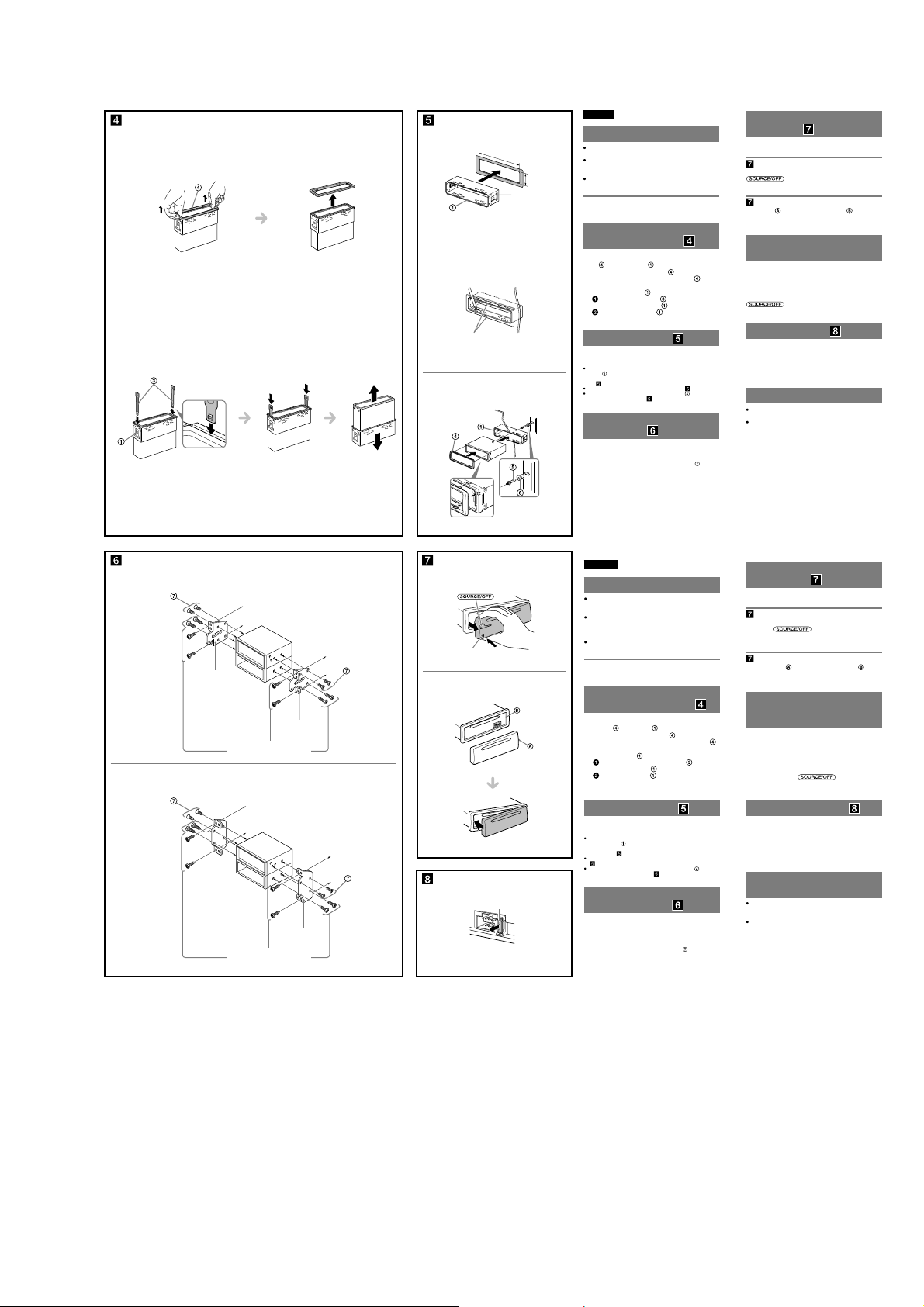
CDX-GT57UPW/GT62UMI/GT570UE/GT570UI/GT570UP/GT574UI/GT620UI/GT626UI
Ver. 1.1
English
1
1
182 mm (7
1
/4 in)
Catch
Enganche
53 mm (2 1/8 in)
2
2
Claws
Uñas
3
Face the hook inwards.
El gancho debe encontrarse
en la parte interior.
Dashboard
Tablero
Fire wall
Cortafuegos
Precautions
Choose the installation location carefully so that the unit
will not interfere with normal driving operations.
Avoid installing the unit in areas subject to dust, dirt,
excessive vibration, or high temperatures, such as in
direct sunlight or near heater ducts.
Use only the supplied mounting hardware for a safe and
secure installation.
Mounting angle adjustment
Adjust the mounting angle to less than 45°.
Removing the protection
collar and the bracket (
Before installing the unit, remove the protection
and the bracket from the unit.
collar
Remove the protection collar .
1
Pinch both edges of the protection collar , then
pull it out.
Remove the bracket .
2
Insert both release keys together between
the unit and the bracket
Pull down the bracket , then pull up the unit
to separate.
)
until they click.
Mounting example ( )
Installation in the dashboard
Notes
Before installing, make sure that the catches on both sides of the
bracket are bent inwards 2 mm (
bent outwards, the unit will not be installed securely and may spring
out( -1).
Bend these claws outward for a tight t, if necessary ( -2).
Make sure that the 4 catches on the protection collar are properly
engaged in the slots of the unit (
Mounting the unit in a
Japanese car (
You may not be able to install this unit in some makes of
Japanese cars. In such a case, consult your Sony dealer.
Note
To prevent malfunction, install only with the supplied screws
3
/32 in). If the catches are straight or
-3).
)
.
How to detach and attach the
front panel (
Before installing the unit, detach the front panel.
-A To detach
Before detaching the front panel, be sure to press and hold
pull it off towards you.
-B To attach
Engage part of the front panel with part of the unit,
as illustrated, and push the le side into position until it
clicks.
Warning if your car’s ignition
has no ACC position
Be sure to set the Auto Off function. For details, see the
supplied Operating Instructions.
e unit will shut off completely and automatically in the
set time aer the unit is turned off, which prevents battery
drain.
If you do not set the Auto Off function, press and hold
you turn the ignition off.
)
. Press the front panel release button, and
until the display disappears each time
Fuse replacement ( )
When replacing the fuse, be sure to use one matching the
amperage rating stated on the original fuse. If the fuse
blows, check the power connection and replace the fuse. If
the fuse blows again after replacement, there may be an
internal malfunction. In such a case, consult your nearest
Sony dealer.
Notes on the tuning step
For how to set the tuning step, see the supplied
Operating Instructions.
If replacing the car battery or changing the connections,
the tuning step setting will be erased.
A TOYOTA
size
5 × max. 8 mm
7
(
/32 × max. 5/16 in)
tamaño
5 × 8 mm máx.
B NISSAN
size
5 × max. 8 mm
7
/32 × max. 5/16 in)
(
tamaño
5 × 8 mm máx.
Bracket
Soporte
Existing parts supplied with your car
Piezas existentes suministradas con su
automóvil
Bracket
Soporte
Existing parts supplied with your car
Piezas existentes suministradas con su
automóvil
to dashboard/center console
al tablero o consola central
Bracket
Soporte
to dashboard/center console
al tablero o consola central
Bracket
Soporte
size
5 × max. 8 mm
7
/32 × max. 5/16 in)
(
tamaño
5 × 8 mm máx.
size
5 × max. 8 mm
7
(
/32 × max. 5/16 in)
tamaño
5 × 8 mm máx.
A
Front panel release button
Botón de liberación del panel frontal
B
Fuse (10 A)
Fusible (10 A)
Español
Precauciones
Elija cuidadosamente el lugar de montaje de forma que
la unidad no interera con las funciones normales de
conducción.
Evite instalar la unidad donde pueda quedar expuesta a
polvo, suciedad, vibraciones excesivas o altas
temperaturas, por ejemplo, a la luz solar directa o cerca
de conductos de calefacción.
Para realizar una instalación segura y rme, utilice
solamente elementos de instalación suministrados.
Ajuste del ángulo de montaje
Ajuste el ángulo de montaje a menos de 45°.
Extracción del marco de
protección y del soporte (
Antes de instalar la unidad, retire el marco de
y el soporte de la misma.
protección
Retire el marco de protección .
1
Apriete ambos bordes del marco de protección
y, a continuación, tire de él hacia fuera.
Retire el soporte .
2
Inserte ambas llaves de liberación entre la
unidad y el soporte hasta que encajen.
Presione el soporte y, a continuación,
levante la unidad para separar ambos
elementos.
Ejemplo de montaje ( )
Instalación en el tablero
Notas
Antes de instalar la unidad, compruebe que los enganches de ambos
lados del soporte
estén doblados hacia adentro 2 mm. Si no lo están
o están doblados hacia afuera, la unidad no se instalará correctamente
-1).
y puede saltar (
Si es necesario, doble las uñas hacia fuera para que encaje rmemente
(
-2).
Compruebe que los 4 enganches del marco de protección estén bien
jados en las ranuras de la unidad (
Montaje de la unidad en un
automóvil japonés (
Es posible que no pueda instalar esta unidad en algunos
automóviles japoneses. En tal caso, consulte a su
distribuidor Sony.
Nota
Para evitar que se produzcan fallas de funcionamiento, realice la
instalación solamente con los tornillos suministrados
-3).
)
.
Forma de extraer e instalar el
panel frontal (
Antes de instalar la unidad, extraiga el panel frontal.
-A Para extraerlo
Antes de extraer el panel frontal, asegúrese de mantener
presionado
liberación del panel frontal y extraiga el panel frontal hacia
usted.
-B Para instalarlo
Coloque la parte del panel frontal en la parte de la
unidad, como se muestra en la ilustración, y después
presione la parte izquierda hasta que encaje.
Advertencia: si el encendido
)
del automóvil no dispone de
una posición ACC
Asegúrese de ajustar la función de desconexión
automática. Para obtener más información, consulte el
manual de instrucciones suministrado.
La unidad se apagará completa y automáticamente en el
tiempo establecido después de que se desconecte la
unidad, lo que evita que se desgaste la batería.
Si no ha ajustado la función de desconexión automática,
mantenga presionado
apague el interruptor de encendido, hasta que la pantalla
desaparezca.
Sustitución del fusible ( )
Al sustituir el fusible, asegúrese de utilizar uno cuyo
amperaje coincida con el especicado en el original. Si el
fusible se funde, verique la conexión de alimentación y
sustitúyalo. Si el fusible vuelve a fundirse después de
sustituirlo, es posible que exista alguna falla de
funcionamiento interno. En tal caso, consulte con el
distribuidor Sony más cercano.
Notas acerca de la
sintonización
Para obtener información sobre cómo ajustar la
sintonización, consulte el manual de instrucciones
suministrado.
Si se reemplaza la batería del auto o se cambian las
conecciones, la configuración de la sintonización se
borrará.
)
. Presione el botón de
cada vez que
15
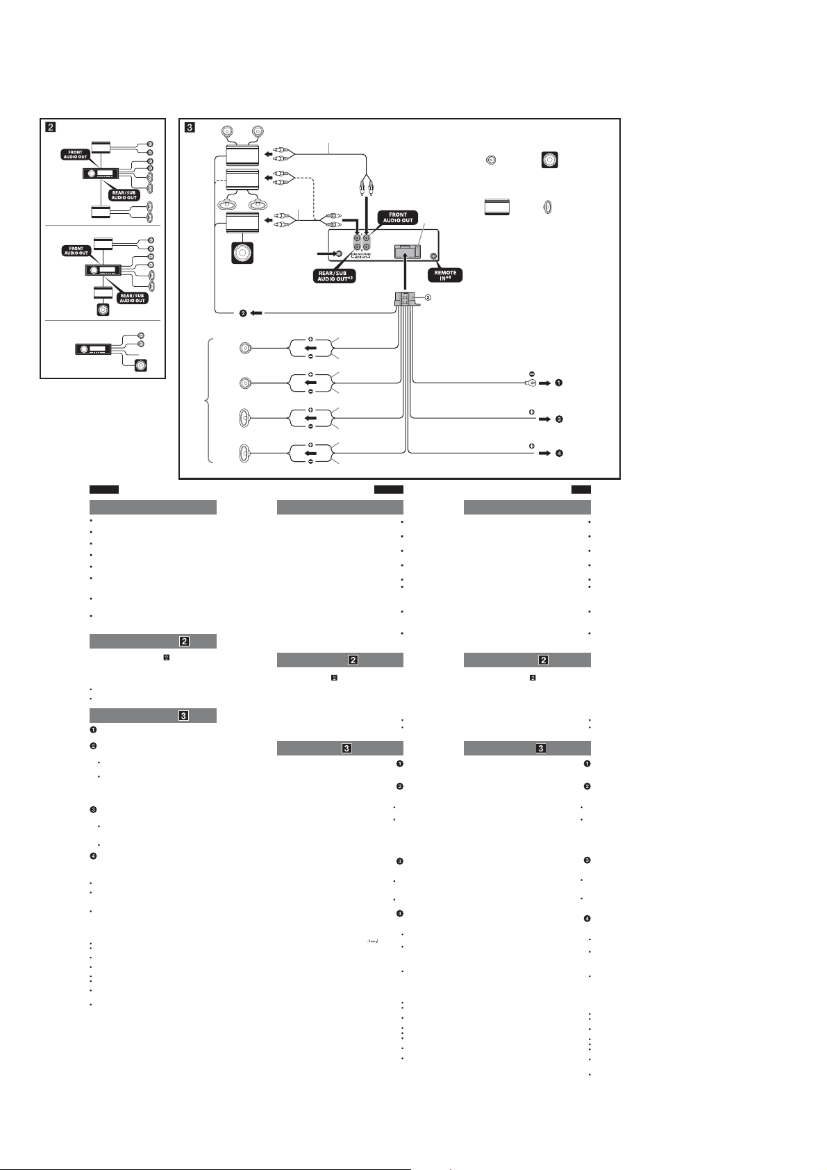
CDX-GT57UPW/GT62UMI/GT570UE/GT570UI/GT570UP/GT574UI/GT620UI/GT626UI
Ver. 1.1
(CDX-GT620UI: Saudi Arabia model)
Equipment used in illustrations (not supplied)
A
2
*
(ﺔﻘﻓﺮﻣ ﺮﻴﻏ) ﺔﻴﺤﻴﺿﻮﺘﻟا لﺎﻜﺷﻷا ﻲﻓ ﺔﻣﺪﺨﺘﺴﻣ ةﺰﻬﺟأ
(ﺖﺴﯿﻧ ﻪﻤﯿﻤﺿ) ﺮﯾوﺎﺼﺗ رد هدﺎﻔﺘﺳا درﻮﻣ تاﺰﯿﻬﺠﺗ
B
C
English
Cautions
is unit is designed for negative ground (earth) 12 V
DC operation only.
Do not get the leads under a screw, or caught in moving
parts (e.g. seat railing).
Before making connections, turn the car ignition off to
avoid short circuits.
Connect the yellow and red power input leads only
after all other leads have been connected.
Run all ground (earth) leads to a common ground
(earth) point.
Be sure to insulate any loose unconnected leads with
electrical tape for safety.
Notes on the power supply lead (yellow)
When connecting this unit in combination with other
stereo components, the connected car circuit’s rating
must be higher than the sum of each component’s fuse.
When no car circuits are rated high enough, connect the
unit directly to the battery.
Connection example ( )
Subwoofer Direct Connection ( -C)
For details on the setting for the connection, see the
supplied Operating Instruction.
* Do not connect a speaker in this connection.
Notes
Be sure to connect the ground (earth) lead before connecting the
amplier.
The alarm will only sound if the built-in amplier is used.
Connection diagram ( )
To a metal surface of the car
First connect the black ground (earth) lead, then connect the yellow,
and red power supply leads.
To the power antenna (aerial) control lead or
power supply lead of antenna (aerial) booster
Notes
It is not necessary to connect this lead if there is no power antenna
(aerial) or antenna (aerial) booster, or with a manually-operated
telescopic antenna (aerial).
When your car has a built-in FM/MW/SW antenna (aerial) in the
rear/side glass, see “Notes on the control and power supply leads.”
To AMP REMOTE IN of an optional power
amplier
This connection is only for ampliers and a power antenna (aerial).
Connecting any other system may damage the unit.
To the +12 V power terminal which is energized in
the accessory position of the ignition key switch
Notes
If there is no accessory position, connect to the +12 V power
(battery) terminal which is energized at all times.
Be sure to connect the black ground (earth) lead to a metal surface
of the car rst.
When your car has a built-in FM/MW/SW antenna (aerial) in the
rear/side glass, see “Notes on the control and power supply leads.”
To the +12 V power terminal which is energized
at all times
Be sure to connect the black ground (earth) lead to a metal surface of
the car rst.
Notes on the control and power supply leads
REM OUT lead (blue/white striped) supplies +12 V DC when you turn on
the unit.
When your car has built-in FM/MW/SW antenna (aerial) in the rear/side
glass, connect REM OUT lead (blue/white striped) or the accessory
power supply lead (red) to the power terminal of the existing antenna
(aerial) booster. For details, consult your dealer.
A power antenna (aerial) without a relay box cannot be used with this
unit.
Memory hold connection
When the yellow power input lead is connected, power will always be
supplied to the memory circuit even when the ignition switch is turned o.
Notes on speaker connection
Before connecting the speakers, turn the unit o.
Use speakers with an impedance of 4 to 8 ohms, and with adequate
power handling capacities to avoid its damage.
Do not connect the speaker terminals to the car chassis, or connect the
terminals of the right speakers with those of the left speaker.
Do not connect the ground (earth) lead of this unit to the negative (–)
terminal of the speaker.
Do not attempt to connect the speakers in parallel.
Connect only passive speakers. Connecting active speakers (with
built-in ampliers) to the speaker terminals may damage the unit.
To avoid a malfunction, do not use the built-in speaker leads installed in
your car if the unit shares a common negative (–) lead for the right and
left speakers.
Do not connect the unit’s speaker leads to each other.
Note on connection
If speaker and amplier are not connected correctly, “FAILURE” appears in
the display. In this case, make sure the speaker and amplier are
connected correctly.
Front speaker
ﺔﻴﻣﺎﻣﻷا ﺔﻋﺎﻤﺴﻟا
ﯽﯾﻮﻠﺟ یﻮﮔﺪﻨﻠﺑ
2
*
from car antenna (aerial)
ةرﺎﻴﺴﻟا ﻲﺋاﻮﻫ ﻦﻣ
وردﻮﺧ ﻦﺘﻧآ زا
Blue/white striped
REM OUT
Max. supply current 0.4 A
0.4
ﺮﻴﺒﻣأ
رﺎﻴﺘﻠﻟ داﺪﻣإ ﻰﺼﻗأ
ﯽﻠﻌﻓ هﺮﯿﺧذ ﺮﺜﮐاﺪﺣ
ﺮﭙﻣآ 0.4
Left
ىﺮﺴﻳ
*
ﭗﭼ
Right
ﻰﻨﻤﻳ
ﺖﺳار
1
*
Left
ىﺮﺴﻳ
ﭗﭼ
Right
ﻰﻨﻤﻳ
ﺖﺳار
ﺾﻴﺑأ/قرزأ ﻂﻄﺨﻣ
ﺪﯿﻔﺳ/ﯽﺑآ هار هار ﻢﯿﺳ
White
ﺾﻴﺑأ
ﺪﯿﻔﺳ
White/black striped
دﻮﺳأ/ﺾﻴﺑأ ﻂﻄﺨﻣ
هﺎﯿﺳ/ﺪﯿﻔﺳ هار هار ﻢﯿﺳ
Gray
يدﺎﻣر
یﺮﺘﺴﮐ ﺎﺧ
Gray/black striped
دﻮﺳأ/يدﺎﻣر ﻂﻄﺨﻣ
هﺎﯿﺳ/یﺮﺘﺴﮐﺎﺧ هار هار ﻢﯿﺳ
Green
ﺮﻀﺧأ
ﺰﺒﺳ
Green/black striped
دﻮﺳأ/ﺮﻀﺧأ ﻂﻄﺨﻣ
هﺎﯿﺳ/ﺰﺒﺳ هار هار ﻢﯿﺳ
Purple
ﻲﺠﺴﻔﻨﺑ
ﯽﻧاﻮﻏرا
Purple/black striped
دﻮﺳأ/ﻲﺠﺴﻔﻨﺑ ﻂﻄﺨﻣ
هﺎﯿﺳ/ﯽﻧاﻮﻏرا هار هار ﻢﯿﺳ
Fuse (10 A)
(ﺮﻴﺒﻣأ 10) ﺮﻬﺼﻨﻣ
10
(ﺮﭙﻣآ
Black
دﻮﺳأ
هﺎﯿﺳ
Red
ﺮﻤﺣأ
ﺰﻣﺮﻗ
Yellow
ﺮﻔﺻأ
درز
) زﻮﯿﻓ
Power amplier
ﻂﺸﻧ ﻢﺨﻀﻣ
ﯽﻗﺮﺑ ﺮﯾﺎﻓ ﯽﻠﭙﻣآ
*1Speaker impedance: 4 – 8 ohms × 4
2
*
RCA pin cord (not supplied).
3
*
AUDIO OUT can be switched SUB or REAR. For details, see the
supplied Operating Instructions.
4
*
Separate adaptor may be required.
،ﻞﻴﺻﺎﻔﺘﻠﻟ .
ﺐﺴﮐ یاﺮﺑ .ﺪﻨﮐ اﺪﯿﭘ ﺮﯿﯿﻐﺗ
.ﺪﯿﻨﮐ هﺪﻫﺎﺸﻣ ار هﺪﺷ ﻪﺋارا ﯽﺗﺎﯿﻠﻤﻋ یﺎﻫ ﻞﻤﻌﻟارﻮﺘﺳد ،تﺎﯿﺋﺰﺟ
ﺔﻴﺑﺮﻌﻟا ﺔﻐﻠﻟا
تﺎﻬﻴﺒﻨﺗ
ﺐﻟﺎﺳ ﺾﻳرﺄﺘﺑ ﻂﻟﻮﻓ12ﺮﺷﺎﺒﻣ رﺎﻴﺘﺑ ﻞﻴﻐﺸﺘﻠﻟ ﺔﻤﻤﺼﻣ ةﺪﺣﻮﻟا هﺬﻫ
ﻰﻠﻋ) ﺔﻛﺮﺤﺘﻤﻟا ءاﺰﺟﻷا ﺲﻣﻼﺗ وأ ،ﻲﻏﺮﺑ ﺖﺤﺗ ﻦﻣ ﺮﻤﺗ كﻼﺳﻷا عﺪﺗ ﻻ
ثوﺪﺣ يدﺎﻔﺘﻟ كﺮﺤﻤﻟا لﺎﻌﺷإ حﺎﺘﻔﻣ ﺊﻔﻃأ ،تﻼﻴﺻﻮﺘﻟا ﺬﻴﻔﻨﺗ ﻞﺒﻗ
ﻦﻣ ءﺎﻬﺘﻧﻻا ﺪﻌﺑ ﻂﻘﻓ ﺮﻤﺣﻷاوﺮﻔﺻﻷا ﺔﻗﺎﻄﻟا ﻞﺧد كﻼﺳأ ﻞﻴﺻﻮﺘﺑ ﻢﻗ
ﻂﻳﺮﺷ لﺎﻤﻌﺘﺳﺎﺑ ﺔﻟﻮﺻﻮﻤﻟا ﺮﻴﻏ كﻼﺳﻷا ﻲﻓ ءﺎﺨﺗرا يأ لﺰﻋ ﻦﻣ ﺪﻛﺄﺗ
نأ ﺐﺠﻳ ،ىﺮﺧأ ﻮﻳﺮﻴﺘﺳ تﺎﻧﻮﻜﻣ ﻊﻣ كاﺮﺘﺷﻻﺎﺑ ةﺪﺣﻮﻟا هﺬﻫ ﻞﻴﺻﻮﺗ ﺪﻨﻋ
ﻦﻣ زﻮﻴﻓ ﻞﻛ راﺪﻘﻣ ﻦﻣ ﻰﻠﻋأ ﺔﻟﻮﺻﻮﻤﻟا ةرﺎﻴﺴﻟا ةﺮﺋاد ةﺮﻳﺎﻌﻣ نﻮﻜﺗ
،ﺔﻳﺎﻔﻜﻟا ﻪﻴﻓ ﺎﻤﺑ ﻊﻔﺗﺮﻣ راﺪﻘﻤﺑ ةﺮﻳﺎﻌﻣ ةرﺎﻴﺴﻟا ﻲﻓ ﺮﺋاود ﺪﺟﻮﺗ ﻻ
.(ﺪﻌﻘﻤﻟا ﻚﻳﺮﺤﺗ نﺎﺒﻀﻗ ،لﺎﺜﻤﻟا ﻞﻴﺒﺳ
.ﻲﺋﺎﺑﺮﻬﻛ سﺎﻤﺗ
.ﺔﻛﺮﺘﺸﻣ ﺾﻳرﺄﺗ ﺔﻄﻘﻧ ﻰﻟإ ﺾﻳرﺄﺘﻟا كﻼﺳأ ﻊﻴﻤﺟ ﺮﻳﺮﻤﺘﺑ ﻢﻗ
.ىﺮﺧﻷا كﻼﺳﻷا ﻞﻴﺻﻮﺗ
.ﺔﻣﻼﺴﻟا نﺎﻤﻀﻟ ﻲﺋﺎﺑﺮﻬﻛ
(ﺮﻔﺻأ) ﺔﻗﺎﻄﻟا داﺪﻣإ ﻚﻠﺳ لﻮﺣ تﺎﻈﺣﻼﻣ
.تﺎﻧﻮﻜﻤﻟا تازﻮﻴﻓ
.ةﺮﺷﺎﺒﻣ ﺔﻳرﺎﻄﺒﻟا ﻰﻟإ زﺎﻬﺠﻟا ﻞﻴﺻﻮﺘﺑ ﻢﻗ
( ) ﻞﻴﺻﻮﺘﻟا لﺎﺜﻣ
( -C)
ﻞﻴﻐﺸﺘﻟا تﺎﻤﻴﻠﻌﺗ ﺮﻈﻧا ،ﺔﻠﺻﻮﻟا داﺪﻋإ لﻮﺣ ﻞﻴﺻﺎﻔﺗ ﻰﻠﻋ لﻮﺼﺤﻠﻟ
تﻮﺼﻟا ﻢﺨﻀﻤﻟ ةﺮﺷﺎﺒﻤﻟا ﺔﻠﺻﻮﻟا
.ﺔﻠﺻﻮﻟا هﺬﻫ ﻲﻓ ﺔﻋﺎﻤﺳ ﺔﻳأ ﻞﻴﺻﻮﺘﺑ ﻢﻘﺗ ﻻ
.تﻮﺼﻟا ﻢﺨﻀﻣ ﻞﻴﺻﻮﺗ ﻞﺒﻗ ﺾﻳرﺄﺘﻟا ﻚﻠﺳ ﻞﻴﺻﻮﺗ ﻦﻣ ﺪﻛﺄﺗ
.ﻲﻠﺧاﺪﻟا تﻮﺼﻟا ﻢﺨﻀﻣ لﺎﻤﻌﺘﺳا ﻢﺗ اذإ ﻂﻘﻓ راﺬﻧإ تﻮﺻ رﺪﺼﻴﺳ
( ) ﻞﻴﺻﻮﺘﻟا ﻂﻄﺨﻣ
ﺮﻔﺻﻷا ﺔﻗﺎﻄﻟا داﺪﻣإ كﻼﺳأ ﻞﻴﺻﻮﺘﺑ ﻢﻗ ﻢﺛ ،دﻮﺳﻷا ﺾﻳرﺄﺘﻟا ﻚﻠﺳ ﻞﻴﺻﻮﺘﺑ ًﻻوأ ﻢﻗ
ﻢﺨﻀﻤﻟ ﺔﻗﺎﻄﻟا داﺪﻣإ ﻚﻠﺳ وأ ﻲﻟﻵا ﻲﺋاﻮﻬﻟﺎﺑ ﻢﻜﺤﺘﻟا ﻚﻠﺳ ﻰﻟإ
زﺰﻌﻣ وأ ﻲﻟآ ﻲﺋاﻮﻫ دﻮﺟو مﺪﻋ ﺔﻟﺎﺣ ﻲﻓ ﻚﻠﺴﻟا اﺬﻫ ﻞﻴﺻﻮﺗ يروﺮﻀﻟا ﻦﻣ ﺲﻴﻟ
جﺎﺟﺰﻟا ﻲﻓ ﺐﻛﺮﻣ ﻲﻠﺧاد
.«ﺔﻗﺎﻄﻟا داﺪﻣإو ﻢﻜﺤﺘﻟا كﻼﺳأ لﻮﺣ تﺎﻈﺣﻼﻣ» ﻊﺟار ،ﻲﺒﻧﺎﺠﻟا /ﻲﻔﻠﺨﻟا
تﻮﺼﻟا ﻢﺨﻀﻣ ﻰﻠﻋ
يأ ﻞﻴﺻﻮﺘﺑ مﺎﻴﻘﻟا .ﻲﻟﻵا ﻲﺋاﻮﻬﻟاو تﻮﺼﻟا تﺎﻤﺨﻀﻤﻟ ﻂﻘﻓ ﺔﺼﺼﺨﻣ ﺔﻠﺻﻮﻟا هﺬﻫ
ﺎﻣﺪﻨﻋ رﺎﻴﺘﻟا ﻪﻴﻓ يﺮﺴﻳ يﺬﻟا ﻂﻟﻮﻓ
ﺔﻗﺎﻄﻟا ﻞﻴﺻﻮﺗ فﺮﻃ ﻰﻟإ ﻞﻴﺻﻮﺘﻟﺎﺑ ﻢﻗ ،تﺎﻴﻟﺎﻤﻜﻟا ﻊﺿﻮﻣ دﻮﺟو مﺪﻋ ﺔﻟﺎﺣ ﻲﻓ
ﻚﻠﺳ ﻞﻴﺻﻮﺗ ﻦﻣ ﺪﻛﺄﺗ .ﺎًﻤﺋاد رﺎﻴﺘﻟا ﻪﻴﻓ يﺮﺴﻳ يﺬﻟا ﻂﻟﻮﻓ
جﺎﺟﺰﻟا ﻲﻓ ﺐﻛﺮﻣ ﻲﻠﺧاد
.«ﺔﻗﺎﻄﻟا داﺪﻣإو ﻢﻜﺤﺘﻟا كﻼﺳأ لﻮﺣ تﺎﻈﺣﻼﻣ» ﻊﺟار ،ﻲﺒﻧﺎﺠﻟا /ﻲﻔﻠﺨﻟا
ﺎًﻤﺋاد رﺎﻴﺘﻟا ﻪﻴﻓ يﺮﺴﻳ يﺬﻟا ﻂﻟﻮﻓ
.ًﻻوأ ةرﺎﻴﺴﻟا ﻦﻣ ﻲﻧﺪﻌﻤﻟا ﺢﻄﺴﻟا ﻰﻟإ دﻮﺳﻷا ﺾﻳرﺄﺘﻟا ﻚﻠﺳ ﻞﻴﺻﻮﺗ ﻦﻣ ﺪﻛﺄﺗ
ﺎﻣﺪﻨﻋ ﻂﻟﻮﻓ
+12ﺮﺷﺎﺒﻣ رﺎﻴﺗ داﺪﻣﺈﺑ مﻮﻘﻳ (ﺾﻴﺑأ/قرزأ ﻂﻄﺨﻣ)REM OUT ﻚﻠﺳ
/ﻲﻔﻠﺨﻟا جﺎﺟﺰﻟا ﻲﻓ ﺐﻛﺮﻣ ﻲﻠﺧاد
ﺔﻗﺎﻄﻟا داﺪﻣإ ﻚﻠﺳ وأ (ﺾﻴﺑأ/قرزأ ﻂﻄﺨﻣ)
لﻮﺼﺤﻠﻟ .ًﻼﺻأ دﻮﺟﻮﻤﻟا ﻲﺋاﻮﻬﻟا زﺰﻌﻤﻟ ﺔﻗﺎﻄﻟا ﻞﻴﺻﻮﺗ فﺮﻃ ﻰﻟإ (ﺮﻤﺣأ) ﺔﻴﻟﺎﻤﻜﻠﻟ
.زﺎﻬﺠﻟا اﺬﻫ ﻲﻓ ﺔﺑوﺎﻨﻣ قوﺪﻨﺻ ﻰﻠﻋ يﻮﺘﺤﻳ ﻻ يﺬﻟا ﻲﻟﻵا ﻲﺋاﻮﻬﻟا لﺎﻤﻌﺘﺳا ﻦﻜﻤﻳ ﻻ
ﻰﺘﺣ ﺎًﻀﻳأ ةﺮﻛاﺬﻟا ةﺮﺋاد ﻰﻟإ ﺔﻗﺎﻄﻟا داﺪﻣإ ﻢﺘﻴﺳ ،ﺮﻔﺻﻷا ﺔﻗﺎﻄﻟا ﻞﺧد ﻚﻠﺳ ﻞﻴﺻﻮﺗ ﺪﻨﻋ
ةرﺪﻘﻟا ﻊﻣ ﻞﻣﺎﻌﺘﻟا ﻰﻠﻋ ةءﻮﻔﻛ تﺎﻴﻠﺑﺎﻗو ،موأ8ﻰﻟإ4ﺔﻗوﺎﻌﻤﺑ تﺎﻋﺎﻤﺳ ﻞﻤﻌﺘﺳا
فاﺮﻃأ ﻞﻴﺻﻮﺗ وأ ،ةرﺎﻴﺴﻟا ﻞﻜﻴﻫ ﻰﻟإ تﺎﻋﺎﻤﺴﻟا ﻞﻴﺻﻮﺗ فاﺮﻃأ ﻞﻴﺻﻮﺘﺑ ﻢﻘﺗ ﻻ
–
) ﺐﻟﺎﺴﻟا ﻞﻴﺻﻮﺘﻟا فﺮﻃ ﻰﻟإ زﺎﻬﺠﻟا اﺬﻫ ﺾﻳرﺄﺗ ﻚﻠﺳ ﻞﻴﺻﻮﺘﺑ ﻢﻘﺗ ﻻ
.ﺔﻋﺎﻤﺴﻠﻟ (
تﺎﻤﺨﻀﻤﺑ) ﺔﻄﺸﻧ تﺎﻋﺎﻤﺳ ﻞﻴﺻﻮﺘﺑ مﺎﻴﻘﻟا .ﻂﻘﻓ ﺔﻟﺎﻌﻓ ﺮﻴﻏ تﺎﻋﺎﻤﺳ ﻞﻴﺻﻮﺘﺑ ﻢﻗ
.زﺎﻬﺠﻟا ﻒﻠﺗ ﻰﻟإ يدﺆﻳ ﺪﻗ تﺎﻋﺎﻤﺴﻟا ﻞﻴﺻﻮﺗ فاﺮﻃأ ﻰﻟإ (ﺔﻴﻠﺧاد تﻮﺻ
اذإ ﻚﺗرﺎﻴﺳ ﻲﻓ ﺔﺒﻛﺮﻤﻟا ﺔﻴﻠﺧاﺪﻟا ﺔﻋﺎﻤﺴﻟا كﻼﺳأ ﻞﻤﻌﺘﺴﺗ ﻻ ،ﻞﻠﺧ ثوﺪﺣ يدﺎﻔﺘﻟ
.ىﺮﺴﻴﻟاو ﻰﻨﻤﻴﻟا تﺎﻋﺎﻤﺴﻠﻟ كﺮﺘﺸﻣ (–) ﺐﻟﺎﺳ ﻚﻠﺳ ﻰﻠﻋ يﻮﺘﺤﻳ زﺎﻬﺠﻟا نﺎﻛ
ﻲﻓ
"FAILURE"ضﺮﻋ ﻢﺘﻴﻓ ،ﺢﻴﺤﺻ ﻞﻜﺸﺑ تﻮﺼﻟا ﻢﺨﻀﻣو ﺔﻋﺎﻤﺴﻟا ﻞﻴﺻﻮﺗ ﻢﺘﻳ ﻢﻟ اذإ
.ﺢﻴﺤﺻ ﻞﻜﺸﺑ تﻮﺼﻟا ﻢﺨﻀﻣو ﺔﻋﺎﻤﺴﻟا ﻞﻴﺻﻮﺗ ﻦﻣ ﺪﻛﺄﺗ ،ﺔﻟﺎﺤﻟا هﺬﻫ ﻲﻓ .ﺔﺷﺎﺸﻟا
ةرﺎﻴﺴﻟا ﻦﻣ ﻲﻧﺪﻌﻣ ﺢﻄﺳ ﻰﻟإ
.ﺮﻤﺣﻷاو
ﻲﺋاﻮﻬﻟا ﻢﺨﻀﻣ زﺰﻌﻣ ﻲﻓ ﺐﻛﺮﻤﻟا تﻮﺼﻟا
.ﺎًﻳوﺪﻳ ﻪﻠﻴﻐﺸﺗ ﻢﺘﻳ ﻲﺑﻮﻜﺴﻠﺗ ﻲﺋاﻮﻫ دﻮﺟو ﺪﻨﻋ وأ ﻲﺋاﻮﻫ
FM/MW/SW
ﻲﺋاﻮﻬﺑ ةﺰﻬﺠﻣ ﻚﺗرﺎﻴﺳ نﻮﻜﺗ ﺎﻣﺪﻨﻋ
AMP REMOTE IN
تﺎﻴﻟﺎﻤﻜﻟا ﻊﺿﻮﻣ ﻲﻓ كﺮﺤﻤﻟا لﺎﻌﺷإ حﺎﺘﻔﻣ نﻮﻜﻳ
.ًﻻوأ ةرﺎﻴﺴﻟا ﻦﻣ ﻲﻧﺪﻌﻤﻟا ﺢﻄﺴﻟا ﻰﻟإ دﻮﺳﻷا ﺾﻳرﺄﺘﻟا
FM/MW/SW
ﻲﺋاﻮﻬﺑ ةﺰﻬﺠﻣ ﻚﺗرﺎﻴﺳ نﻮﻜﺗ ﺎﻣﺪﻨﻋ
ﺔﻗﺎﻄﻟا داﺪﻣإو ﻢﻜﺤﺘﻟا كﻼﺳأ لﻮﺣ تﺎﻈﺣﻼﻣ
FM/MW/SW
.فﺎﻘﻳﻹا ﻊﺿو ﻲﻓ كﺮﺤﻤﻟا لﺎﻌﺷإ حﺎﺘﻔﻣ نﻮﻜﻳ ﺎﻣﺪﻨﻋ
.ىﺮﺴﻴﻟا تﺎﻋﺎﻤﺴﻟا ﻞﻴﺻﻮﺗ فاﺮﻃﺄﺑ ﻰﻨﻤﻴﻟا تﺎﻋﺎﻤﺴﻟا ﻞﻴﺻﻮﺗ
.يزاﻮﺘﻟا ﻰﻠﻋ تﺎﻋﺎﻤﺴﻟا ﻞﻴﺻﻮﺗ لوﺎﺤﺗ ﻻ
.ﺾﻌﺒﻟا ﺎﻬﻀﻌﺒﺑ زﺎﻬﺠﻟا ﺔﻋﺎﻤﺳ كﻼﺳأ ﻞﻴﺻﻮﺘﺑ ﻢﻘﺗ ﻻ
ﻞﻴﺻﻮﺘﻟا فﺮﻃ ﻰﻟإ
يرﺎﻴﺘﺧﻻا ﻂﺸﻨﻟا
.زﺎﻬﺠﻟا ﻒﻠﺘﻳ ﺪﻗ ﺮﺧآ مﺎﻈﻧ
+12
ﺔﻗﺎﻄﻟا ﻞﻴﺻﻮﺗ فﺮﻃ ﻰﻟإ
+12
(ﺔﻳرﺎﻄﺑ)
+12
ﺔﻗﺎﻄﻟا ﻞﻴﺻﻮﺗ فﺮﻃ ﻰﻟإ
ا ﻞﻴﻐﺸﺘﺑ مﻮﻘﺗ
ﻲﺋاﻮﻬﺑ ةﺰﻬﺠﻣ ﻚﺗرﺎﻴﺳ نﻮﻜﺗ ﺎﻣﺪﻨﻋ
ﻚﻠﺳ ﻞﻴﺻﻮﺘﺑ ﻢﻗ ،ﻲﺒﻧﺎﺠﻟا
REM OUT
.ﻞﻴﻛﻮﻟا ﺮﺸﺘﺳا ،ﻞﻴﺻﺎﻔﺗ ﻰﻠﻋ
ةﺮﻛاﺬﻟا ﻆﻔﺣ ﻞﻴﺻﻮﺗ
ﺔﻋﺎﻤﺴﻟا ﻞﻴﺻﻮﺗ لﻮﺣ تﺎﻈﺣﻼﻣ
.زﺎﻬﺠﻟا ﺊﻔﻃأ ،تﺎﻋﺎﻤﺴﻟا ﻞﻴﺻﻮﺗ ﻞﺒﻗ
.ﻒﻠﺘﻠﻟ ﺎﻬﺿﺮﻌﺗ يدﺎﻔﺘﻟ
ﻞﻴﺻﻮﺘﻟا لﻮﺣ ﺔﻈﺣﻼﻣ
تﺎﻈﺣﻼﻣ
تﺎﻈﺣﻼﻣ
.ﻂﻘﻓ
ﺎﻣﺪﻨﻋ
.ﺔﻘﻓﺮﻤﻟا
تﺎﻈﺣﻼﻣ
*
ﻦﯿﻣز ﯽﻔﻨﻣ ﺖﻟو 12 ﻢﯿﻘﺘﺴﻣ قﺮﺑ تﺎﯿﻠﻤﻋ یاﺮﺑ ﺎﻬﻨﺗ هﺎﮕﺘﺳد
لﺎﺜﻣ یاﺮﺑ) کﺮﺤﺘﻣ تﺎﻌﻄﻗ نﺎﯿﻣ ﺎﯾ ،ﺪﯿﻫﺪﻧ راﺮﻗ ﭻﯿﭘ ﮏﯾ ﺮﯾز ار
زا ﺎﺗ ﺪﯿﻨﮐ شﻮﻣﺎﺧ ار ﻞﯿﺒﻣﻮﺗا ترﺎﺘﺳا ﭻﯿﯾﻮﺳ ،تﻻﺎﺼﺗا دﺎﺠﯾا زا
ﻞﺻو ﺎﻫ ﻢﯿﺳ ﺮﯾﺎﺳ ﻪﮐ ﯽﻣﺎﮕﻨﻫ ﺎﻬﻨﺗ ار ﺰﻣﺮﻗ و درز قﺮﺑ ﻊﺒﻨﻣ یﺎﻫ
.ﺪﯿﺸﮑﺑ ﻦﯿﻣز کﺮﺘﺸﻣ ﻪﻄﻘﻧ ﮏﯾ ﻪﺑ ار ﻦﯿﻣز یﺎﻫ ﻢﯿﺳ
ﯽﻗﺮﺑ ﺐﺴﭼ راﻮﻧ ﺎﺑ ار ﻞﺷ هﺪﺸﻧ ﻞﺻو ﻢﯿﺳ ﺮﻫ ﯽﻨﻤﯾا رﻮﻈﻨﻣ ﻪﺑ
،ﺮﮕﯾد ﻮﯾﺮﺘﺳا یﺎﻫ هﺎﮕﺘﺳد ﺎﺑ ﺐﯿﮐﺮﺗ رد هﺎﮕﺘﺳد ﻦﯾا ندﺮﮐ ﻞﺻو
ﺮﺗﻻﺎﺑ هﺎﮕﺘﺳد ﺮﻫ زﻮﯿﻓ عﻮﻤﺠﻣ زا ﺪﯾﺎﺑ هﺪﺷ ﻞﺻو ﻞﯿﺒﻣﻮﺗا راﺪﻣ ﺢﻄﺳ
ار هﺎﮕﺘﺳد ،ﺖﺴﯿﻧ ﻻﺎﺑ ﯽﻓﺎﮐ هزاﺪﻧا ﻪﺑ ﻞﯿﺒﻣﻮﺗا راﺪﻣ ﭻﯿﻫ ﻪﮐ
ﯽﺗﺎﯿﻠﻤﻋ یﺎﻫ ﻞﻤﻌﻟارﻮﺘﺳد ﻪﺑ ،لﺎﺼﺗا ﻪﺑ طﻮﺑﺮﻣ تﺎﯿﺋﺰﺟ صﻮﺼﺧرد
.ﺪﻨﮐ ﯽﻣ اﺪﺻ ﮓﻧز ﯽﻠﺧاد ﺮﯾﺎﻓ ﯽﻠﭙﻣآ زا هدﺎﻔﺘﺳا مﺎﮕﻨﻫ ﺎﻬﻨﺗ
ﻞﺻو ار ﺰﻣﺮﻗ و درز ﻊﺒﻨﻣ یﺎﻫ ﻢﯿﺳ ﺲﭙﺳ ،ﺪﯿﻨﮐ ﻞﺻو ار ﻦﯿﻣز هﺎﯿﺳ ﻢﯿﺳ اﺪﺘﺑا
ﺮﯾﺎﻓ ﯽﻠﭙﻣآ قﺮﺑ ﻊﺒﻨﻣ ﻢﯿﺳ ﺎﯾ ﯽﻗﺮﺑ ﯽﯾاﻮﻫ ﻦﺘﻧآ لﺮﺘﻨﮐ ﻢﯿﺳ ﻪﺑ
،دراﺪﻧ دﻮﺟو ﯽﯾاﻮﻫ ﻦﺘﻧآ هﺪﻨﻨﮐ ﺖﯾﻮﻘﺗ ﺎﯾ ﯽﻗﺮﺑ ﯽﯾاﻮﻫ ﻦﺘﻧآ ﻪﮐ ﯽﺗرﻮﺻ رد
FM/MW/SW
ﻪﺸﯿﺷ رد
ار "قﺮﺑ ﻊﺒﻨﻣ و لﺮﺘﻨﮐ یﺎﻫ ﻢﯿﺳ درﻮﻣ رد تﺎﮑﻧ" ،ﺪﺷﺎﺑ ﯽﻣ یرﺎﻨﮐ/ﯽﺒﻘﻋ
یرﺎﯿﺘﺧا ﯽﻗﺮﺑ ﺮﯾﺎﻓ ﯽﻠﭙﻣآ ﮏﯾ
ﻢﺘﺴﯿﺳ ﺮﻫ لﺎﺼﺗا .ﺖﺳا یﻮﻗ ﻦﺘﻧآ ﮏﯾ و ﺎﻫﺮﯾﺎﻓ ﯽﻠﭙﻣآ یاﺮﺑ ﺎﻬﻨﺗ لﺎﺼﺗا ﻦﯾا
ﭻﯿﯾﻮﺳ ﺪﯿﻠﮐ ﯽﺒﻧﺎﺟ ﺖﯿﻌﻗﻮﻣ رد ﻪﮐ ﺖﻟو
+12
ﻪﮐ ﺖﻟو
(یﺮﺗﺎﺑ) قﺮﺑ لﺎﻨﯿﻣﺮﺗ ﻪﺑ ،دراﺪﻧ دﻮﺟو ﯽﺒﻧﺎﺟ ﺖﯿﻌﻗﻮﻣ ﭻﯿﻫ ﺮﮔا
یﺰﻠﻓ ﺢﻄﺳ ﻪﺑ ار ﻦﯿﻣز هﺎﯿﺳ ﻢﯿﺳ اﺪﺘﺑا ﺎﻤﺘﺣ .ﺪﯿﻨﮐ ﻞﺻو دﺮﯿﮔ ﯽﻣ وﺮﯿﻧ هراﻮﻤﻫ
FM/MW/SW
ﻪﺸﯿﺷ رد
ار "قﺮﺑ ﻊﺒﻨﻣ و لﺮﺘﻨﮐ یﺎﻫ ﻢﯿﺳ درﻮﻣ رد ﻰﺗﺎﮑﻧ" ،ﺪﺷﺎﺑ ﯽﻣ یرﺎﻨﮐ/ﯽﺒﻘﻋ
دﺮﯿﮔ ﯽﻣ وﺮﯿﻧ هراﻮﻤﻫ ﻪﮐ ﺖﻟو
.ﺪﯿﻨﮐ ﻞﺻو ﻞﯿﺒﻣﻮﺗا یﺰﻠﻓ ﺢﻄﺳ ﻪﺑ ار ﻦﯿﻣز هﺎﯿﺳ ﻢﯿﺳ اﺪﺘﺑا ﺎﻤﺘﺣ
ﻢﯿﻘﺘﺴﻣ قﺮﺑ (هار هار ﺪﯿﻔﺳ/ﯽﺑآ)
+12
FM/MW/SW
/ﯽﺒﻘﻋ ﻪﺸﯿﺷ رد
ار (ﺰﻣﺮﻗ) ﯽﺒﻧﺎﺟ قﺮﺑ ﻊﺒﻨﻣ ﻢﯿﺳ ﺎﯾ (هار هار ﺪﯿﻔﺳ/ﯽﺑآ)
هﺪﻨﺷوﺮﻓ ﺎﺑ تﺎﯿﺋﺰﺟ یاﺮﺑ .ﺪﯿﻨﮐ ﻞﺼﺘﻣ دﻮﺟﻮﻣ ﻦﺘﻧآ هﺪﻨﻨﮐ ﺖﯾﻮﻘﺗ قﺮﺑ لﺎﻨﯿﻣﺮﺗ ﻪﺑ
هدﺎﻔﺘﺳا درﻮﻣ هﺎﮕﺘﺳد ﻦﯾا ﺎﺑ ﺪﻧاﻮﺗ ﯽﻤﻧ ﺖﯾﻮﻘﺗ هﺎﮕﺘﺴﯾا ﮏﯾ نوﺪﺑ ﯽﯾاﻮﻫ ﻦﺘﻧآ
ﯽﻣ هداد ﻪﻈﻓﺎﺣ راﺪﻣ ﻪﺑ هراﻮﻤﻫ قﺮﺑ ،ﺖﺳا هﺪﺷ ﻞﺻو درز قﺮﺑ ﻊﺒﻨﻣ ﻢﯿﺳ ﻪﮐ ﯽﻣﺎﮕﻨﻫ
ﻪﻣﺪﺻ زا ﺎﺗ ﺪﯿﻨﮐ هدﺎﻔﺘﺳا قﺮﺑ یﻻﺎﺑ ﺖﯿﻓﺮﻇ ﺎﺑ و
یﺎﻫﻮﮔﺪﻨﻠﺑ یﺎﻫ لﺎﻨﯿﻣﺮﺗ ﺎﯾ ،ﺪﯿﻨﮑﻧ ﻞﺻو ﻞﯿﺒﻣﻮﺗا ﯽﺳﺎﺷ ﻪﺑ ار ﻮﮔﺪﻨﻠﺑ یﺎﻫ
.ﺪﯿﻨﮑﻧ ﻞﺻو ﻮﮔﺪﻨﻠﺑ (
ﺖﯾﻮﻘﺗ ﺎﺑ) لﺎﻌﻓ یﺎﻫﻮﮔﺪﻨﻠﺑ ندﺮﮐ ﻞﺻو .ﺪﯿﻨﮐ ﻞﺻو ار لﺎﻌﻓ ﺮﯿﻏ یﺎﻫﻮﮔﺪﻨﻠﺑ
.ﺪﻨﮐ دراو ﻪﻣﺪﺻ هﺎﮕﺘﺳد ﻪﺑ ﺖﺳا ﻦﮑﻤﻣ ﻮﮔﺪﻨﻠﺑ یﺎﻫ لﺎﻨﯿﻣﺮﺗ ﻪﺑ (ﯽﻠﺧاد یﺎﻫ هﺪﻨﻨﮐ
رد هﺪﺷ ﺐﺼﻧ ﯽﻠﺧاد یﻮﮔﺪﻨﻠﺑ یﺎﻫ ﻢﯿﺳ زا ،دﺮﮑﻠﻤﻋ ءﻮﺳ ﮏﯾ زا بﺎﻨﺘﺟا
یاﺮﺑ کﺮﺘﺸﻣ (–)
ﺶﯾﺎﻤﻧ ﻪﺤﻔﺻ رد
"FAILURE" ،ﺪﻨﺷﺎﺑ هﺪﺸﻧ ﻞﺻو ﺢﯿﺤﺻ رﻮﻄﺑ ﺮﯾﺎﻓ ﯽﻠﭙﻣآ و ﻮﮔﺪﻨﻠﺑ ﺮﮔا
ﺢﯿﺤﺻ رﻮﻄﺑ ﺮﯾﺎﻓ ﯽﻠﭙﻣآ و ﻮﮔﺪﻨﻠﺑ ﻪﮐ ﺪﯾﻮﺷ ﻦﺌﻤﻄﻣ ،ﯽﺘﻟﺎﺣ ﻦﯿﻨﭼ رد .دﻮﺷ ﯽﻣ ﺮﻫﺎﻇ
Subwoofer
تﻮﺼﻟا ﻢﺨﻀ ﻣ
ﺮﻓوﻮﺑﺎﺳ
Rear speaker
ﺔﻴﻔﻠﺨﻟا ﺔﻋﺎﻤﺴﻟا
ﯽﺒﻘﻋ یﻮﮔﺪﻨﻠﺑ
4 × موأ 8 – 4 :ﺔﻋﺎﻤﺴﻟا ﺔﻗوﺎﻌﻣ
RCA
.(ﻖﻓﺮﻣ ﺮﻴﻏ)
AUDIO OUT
تﻮﺼﻟا جﺮﺧ ﺮﻴﻴﻐﺗ ﻦﻜﻤﻳ
.ﺔﻘﻓﺮﻤﻟا ﻞﻴﻐﺸﺘﻟا تﺎﻤﻴﻠﻌﺗ ﻊﺟار
.ﻞﺼﻔﻨﻣ ﺊﻳﺎﻬﻣ ﺮﻓﻮﺗ مﺰﻠﻳ ﺪﻗ
4 × ﻢﻫا 8 ﺎﺗ 4 :ﻮﮔﺪﻨﻠﺑ ﺲﻧاﺪﭙﻣا
.(ﺖﺳا هﺪﺸﻧ ﻪﺋارا)
SUB
ﺎﯾ
ﻪﺑ ﺪﻧاﻮﺗ ﯽﻣ
ﻲﺳﻮﺑد ﻚﻠﺳ
RCA
AUDIO OUT3*
REAR
SUB
وأ
ﻦﻴﺑ
REAR
.ﺪﺷﺎﺑ مزﻻ ﻪﻧﺎﮔاﺪﺟ رﻮﺘﭘادآ ﺖﺳا ﻦﮑﻤﻣ
ACC
BATTERY
تﺎﻃﺎﯿﺘﺣا
.ﺖﺳا هﺪﺷ ﯽﺣاﺮﻃ
.ﺪﯿﻫﺪﻧ ﺮﯿﮔ (ﯽﻟﺪﻨﺻ ﻞﯾر
.ﺪﯿﻨﮐ یﺮﯿﮔﻮﻠﺟ هﺎﺗﻮﮐ تﻻﺎﺼﺗا
.ﺪﯿﻨﮐ ﻞﺻو ﺪﻧا هﺪﺷ
.ﺪﯿﻨﮐ یﺪﻨﺑ ﻖﯾﺎﻋ
(درز) قﺮﺑ ﻊﺒﻨﻣ ﻢﯿﺳ درﻮﻣ رد تﺎﮑﻧ
( -C)
.ﺪﯿﻨﮐ ﻞﺻو ﺮﯾﺎﻓ ﯽﻠﭙﻣآ لﺎﺼﺗا زا ﺶﯿﭘ ار ﻦﯿﻣز ﻢﯿﺳ ﺎﻤﺘﺣ
( ) لﺎﺼﺗا رادﻮﻤﻧ
ﻞﯿﺒﻣﻮﺗا یﺰﻠﻓ ﺢﻄﺳ ﮏﯾ ﻪﺑ
.ﺖﺴﯿﻧ یروﺮﺿ ﻢﯿﺳ ﻦﯾا ندﺮﮐ ﻞﺻو
ﯽﯾاﻮﻫ ﻦﺘﻧآ ﮏﯾ یاراد ﺎﻤﺷ ﻞﯿﺒﻣﻮﺗا ﻪﮐ ﯽﻣﺎﮕﻨﻫ
.دﻮﺷ هﺎﮕﺘﺳد ﻪﺑ ﻪﻣﺪﺻ ﺚﻋﺎﺑ ﺪﻧاﻮﺗ ﯽﻣ یﺮﮕﯾد
ﯽﯾاﻮﻫ ﻦﺘﻧآ ﮏﯾ یاراد ﺎﻤﺷ ﻞﯿﺒﻣﻮﺗا ﻪﮐ ﯽﻣﺎﮕﻨﻫ
قﺮﺑ ﻊﺒﻨﻣ و لﺮﺘﻨﮐ یﺎﻫ ﻢﯿﺳ درﻮﻣ رد ﯽﺗﺎﮑﻧ
REM OUT
ﯽﯾاﻮﻫ ﻦﺘﻧآ ﮏﯾ یاراد ﺎﻤﺷ ﻞﯿﺒﻣﻮﺗا ﻪﮐ ﯽﻣﺎﮕﻨﻫ
.ﺪﺷﺎﺑ شﻮﻣﺎﺧ قاﺮﺘﺣا ﺪﯿﻠﮐ ﻪﮐ ﯽﻣﺎﮕﻨﻫ ﯽﺘﺣ دﻮﺷ
.ﺪﯿﻨﮐ شﻮﻣﺎﺧ ار هﺎﮕﺘﺳد ،ﺎﻫﻮﮔﺪﻨﻠﺑ ندﺮﮐ ﻞﺻو زا
.ﺪﯿﻨﮑﻧ ﻞﺻو ﭗﭼ یﺎﻫﻮﮔﺪﻨﻠﺑ یﺎﻫ لﺎﻨﯿﻣﺮﺗ ﻪﺑ ار ﺖﺳار
–
)
ﯽﻔﻨﻣ لﺎﻨﯿﻣﺮﺗ ﻪﺑ ار هﺎﮕﺘﺳد ﻦﯾا ﻦﯿﻣز
.ﺪﯿﻨﮐ ﻞﺻو یزاﻮﻣ رﻮﻄﺑ ار ﺎﻫﻮﮔﺪﻨﻠﺑ ﺪﯿﻨﮑﻧ
ﯽﻔﻨﻣ ﻢﯿﺳ ﮏﯾ یاراد هﺎﮕﺘﺳد ﻪﮐ ﯽﺗرﻮﺻ رد دﻮﺧ ﻞﯿﺒﻣﻮﺗا
.ﺪﯿﻨﮑﻧ هدﺎﻔﺘﺳا ﺪﺷﺎﺑ ﯽﻣ ﭗﭼ و ﺖﺳار یﺎﻫﻮﮔﺪﻨﻠﺑ
.ﺪﯿﻨﮑﻧ ﻞﺻو ﺮﮕﯾﺪﮑﯾ ﻪﺑ ار هﺎﮕﺘﺳد یﻮﮔﺪﻨﻠﺑ یﺎﻫ
ﯽﻣﺎﮕﻨﻫ
.ﺪﯿﻨﮐ ﻞﺻو یﺮﺗﺎﺑ ﻪﺑ ﺎﻤﯿﻘﺘﺴﻣ
( ) لﺎﺼﺗا ﻪﻧﻮﻤﻧ
ﺮﻓوو بﺎﺳ ﻢﯿﻘﺘﺴﻣ لﺎﺼﺗا
.ﺪﯿﻨﮐ ﻪﻌﺟاﺮﻣ ﻪﻤﯿﻤﺿ
.ﺪﯿﻨﮑﻧ ﻞﺻو ﻮﮔﺪﻨﻠﺑ لﺎﺼﺗا ﻦﯾا رد
ﯽﯾاﻮﻫ ﻦﺘﻧآ هﺪﻨﻨﮐ ﺖﯾﻮﻘﺗ
.ﺪﯿﯾﺎﻤﻧ ﻪﻈﺣﻼﻣ
AMP REMOTE IN
+12
قﺮﺑ لﺎﻨ ﯿﻣﺮﺗ ﻪﺑ
دﺮﯿﮔ ﯽﻣ وﺮﯿﻧ ترﺎﺘﺳا
.ﺪﯿﻨﮐ ﻞﺻو ﻞﯿﺒﻣﻮﺗا
.ﺪﯿﯾﺎﻤﻧ ﻪﻈﺣﻼﻣ
+12
قﺮﺑ لﺎﻨ ﯿﻣﺮﺗ ﻪﺑ
ﻢﯿﺳ ،هﺎﮕﺘﺳد ندﺮﮐ ﻦﺷور مﺎﮕﻨﻫ
.ﺪﻨﮐ ﯽﻣ ﺪﯿﻟﻮﺗ ار
REM OUT
ﻢﯿﺳ ،ﺖﺳا یرﺎﻨﮐ
.ﺪﯿﯾﺎﻤﻧ ترﻮﺸﻣ دﻮﺧ
.دﺮﯿﮔ راﺮﻗ
ﻪﻈﻓﺎﺣ ﻆﻔﺣ لﺎﺼﺗا
ﻮﮔﺪﻨﻠﺑ لﺎﺼﺗا درﻮﻣ رد ﯽﺗﺎﮑﻧ
،ﻢﻫا
8ﺎﺗ4
ﺲﻧاﺪﭙﻣا ﺎﺑ ﺎﻫﻮﮔﺪﻨﻠﺑ
.دﻮﺷ یﺮﯿﮔﻮﻠﺟ نآ ﻪﺑ
لﺎﺼﺗا درﻮﻣ رد یا ﻪﺘﮑﻧ
.ﺪﻧا هﺪﺷ ﺐﺼﻧ
مﺎﮕﻨﻫ
تﺎﮑﻧ
تﺎﮑﻧ
ﻦﯿﭘ ﻢﯿﺳ
ﯽﺳرﺎﻓ
ﺎﻤﺘﺣ
.ﺪﺷﺎﺑ
.ﺪﯿﻨﮐ
لﺎﻨﯿﻣﺮﺗ
1
*
2
*
3
*
4
*
1
*
2
*
4
*
ﻦﯾا
ﻢﯿﺳ
ﻞﺒﻗ
ﻢﯿﺳ
مﺎﻤﺗ
*
تﺎﮑﻧ
ﻪﺑ
ﮏﯾ
ﺶﯿﭘ
زا
ﻢﯿﺳ
ﯽﻌﺳ
ﺎﻬﻨﺗ
یاﺮﺑ
ﻢﯿﺳ
16
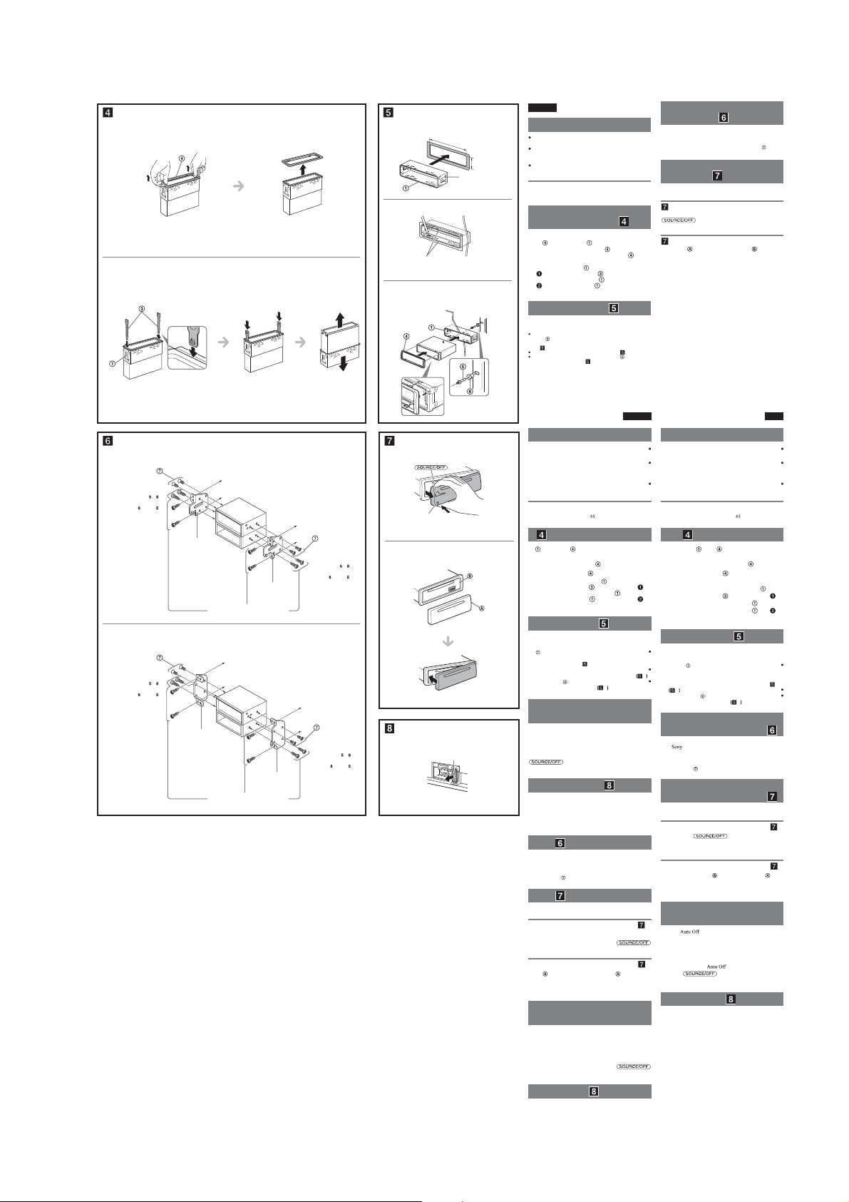
CDX-GT57UPW/GT62UMI/GT570UE/GT570UI/GT570UP/GT574UI/GT620UI/GT626UI
Ver. 1.1
1
2
A TOYOTA
size
5 × max. 8 mm
7
/32 × max. 5/16 in)
(
ﻢﺠﺤﻟا
×
ﻰﺼﻗأ ﺪﺤﻛ ﻢﻠﻣ
هزا ﺪ ﻧا
×
ﺮﺘﻤﯿﻠﯿﻣ ﺮﺜﮐاﺪﺣ
B NISSAN
size
5 × max. 8 mm
7
/32 × max. 5/16 in)
(
ﻢﺠﺤﻟا
×
ﻰﺼﻗأ ﺪﺤﻛ ﻢﻠﻣ
هزا ﺪ ﻧا
×
ﺮﺘﻤﯿﻠﯿﻣ ﺮﺜﮐاﺪﺣ
Face the hook inwards.
.ﻞﺧاﺪﻠﻟ ﺎًﻬﺠﺘﻣ فﺎﻄﺨﻟا ﻞﻌﺟا
.ﺪﯿﻫد راﺮﻗ ﻞﺧاد ﻪﺑ ور ار بﻼﻗ
Bracket
ﺐﻴﻛﺮﺘﻟا ةﺪﻋﺎﻗ
بﻼﻗ
Bracket
ﺐﻴﻛﺮﺘﻟا ةﺪﻋﺎﻗ
بﻼﻗ
to dashboard/center console
ﻂﺳوﻷا يوﺎﺤﻟا قوﺪﻨﺼﻟا/تاداﺪﻌﻟا ﺔﺣﻮﻟ ﻰﻟإ
یﺰﮐﺮﻣ ﻪﻧﺎﯾﺎﭘ/درﻮﺒﺷاد ﻪﺑ
Bracket
ﺐﻴﻛﺮﺘﻟا ةﺪﻋﺎﻗ
Existing parts supplied with your car
ﻚﺗرﺎﻴﺳ ﻊﻣ ﺔﻘﻓﺮﻣ ةدﻮﺟﻮﻤﻟا ءاﺰﺟﻷا
دﻮﺧ ﻞﯿﺒﻣﻮﺗا ﺎﺑ هﺪﺷ ﻪﻤﯿﻤﺿ دﻮﺟﻮﻣ یﺎﻫ ﺖﻤﺴﻗ
Existing parts supplied with your car
ﻚﺗرﺎﻴﺳ ﻊﻣ ﺔﻘﻓﺮﻣ ةدﻮﺟﻮﻤﻟا ءاﺰﺟﻷا
دﻮﺧ ﻞﯿﺒﻣﻮﺗا ﺎﺑ هﺪﺷ ﻪﻤﯿﻤﺿ دﻮﺟﻮﻣ یﺎﻫ ﺖﻤﺴﻗ
بﻼﻗ
to dashboard/center console
ﻂﺳوﻷا يوﺎﺤﻟا قوﺪﻨﺼﻟا/تاداﺪﻌﻟا ﺔﺣﻮﻟ ﻰﻟإ
یﺰﮐﺮﻣ ﻪﻧﺎﯾﺎﭘ/درﻮﺒﺷاد ﻪﺑ
Bracket
ﺐﻴﻛﺮﺘﻟا ةﺪﻋﺎﻗ
بﻼﻗ
size
5 × max. 8 mm
7
(
/32 × max. 5/16 in)
ﻰﺼﻗأ ﺪﺤﻛ ﻢﻠﻣ
ﺮﺘﻤﯿﻠﯿﻣ ﺮﺜﮐاﺪﺣ
size
5 × max. 8 mm
7
(
/32 × max. 5/16 in)
ﻰﺼﻗأ ﺪﺤﻛ ﻢﻠﻣ
ﺮﺘﻤﯿﻠﯿﻣ ﺮﺜﮐاﺪﺣ
English
1
182 mm (71/4 in)
53 mm (2
Catch
جﻻﺰﻣ
هﺮﯿﮔ
2
Claws
ﺐﻟﺎﺨﻣ
ﺎﻫ هﺮﯿﮔ
3
Dashboard
تاداﺪﻌﻟا ﺔﺣﻮﻟ
درﻮﺒ ﺷ اد
Firewall
ﻞﺼﻔﻟا راﺪﺟ
ﻦﯿﺸﺗآ راﻮﯾد
Precautions
Choose the installation location carefully so that the unit
will not interfere with normal driving operations.
Avoid installing the unit in areas subject to dust, dirt,
excessive vibration, or high temperatures, such as in
direct sunlight or near heater ducts.
1
/8 in)
Use only the supplied mounting hardware for a safe and
secure installation.
Mounting angle adjustment
Adjust the mounting angle to less than 45°.
Removing the protection
collar and the bracket (
Before installing the unit, remove the protection
and the bracket from the unit.
collar
Remove the protection collar .
1
Pinch both edges of the protection collar , then
pull it out.
Remove the bracket .
2
Insert both release keys together between
the unit and the bracket
Pull down the bracket , then pull up the unit
to separate.
Mounting example ( )
Installation in the dashboard
Notes
Before installing, make sure that the catches on both sides of the
bracket
are bent inwards 2 mm (
bent outwards, the unit will not be installed securely and may spring
out
-1).
(
Bend these claws outward for a tight t, if necessary ( -2).
Make sure that the 4 catches on the protection collar are properly
engaged in the slots of the unit (
until they click.
3
/32 in). If the catches are straight or
-3).
ﺔﻴﻃﺎﻴﺘﺣا تﺎﻬﻴﺒﻨﺗ
A
تﺎﻴﻠﻤﻋ ﻊﻣ ةﺪﺣﻮﻟا ﻞﺧاﺪﺘﺗ ﻻ ﺚﻴﺤﺑ ﺔﻳﺎﻨﻌﺑ ﺐﻴﻛﺮﺘﻟا ﻊﺿﻮﻣ ﺮﺘﺧا
زاﺰﺘﻫﻻا وأ خﺎﺳوﻷا وأ رﺎﺒﻐﻠﻟ ﺔﺿﺮﻌﻣ ﻦﻛﺎﻣأ ﻲﻓ زﺎﻬﺠﻟا ﺐﻴﻛﺮﺗ ﺐﻨﺠﺗ
ﺲﻤﺸﻟا ﺔﻌﺷأ ﺖﺤﺗ نﻮﻜﺗ نﺄﻛ ،ﺔﻴﻟﺎﻌﻟا ةراﺮﺤﻟا تﺎﺟرد وأ طﺮﻔﻤﻟا
ﺐﻴﻛﺮﺘﻟاو ﺔﻣﻼﺴﻟا ﻖﻴﻘﺤﺘﻟ ﻚﻟذو ﻂﻘﻓ ﺔﻘﻓﺮﻤﻟا ﺐﻴﻛﺮﺘﻟا ةادأ ﻞﻤﻌﺘﺳا
Front panel release button
ﺔﻴﻣﺎﻣﻷا ﺔﺣﻮﻠﻟا ﺮﻳﺮﺤﺗ رز
ﻮﻠﺟ ﻪﺤﻔﺻ یزﺎﺳﺎﻫر ﻪﻤﮐد
ﻢﺠﺤﻟا
×
هزا ﺪ ﻧا
×
B
ةﺪﻋﺎﻗو زﺎﻬﺠﻟا ﻦﻴﺑ ﺪﺣاو نآ ﻲﻓ ﺮﻳﺮﺤﺘﻟا ﻲﺣﺎﺘﻔﻣ ﻞﺧدأ
.ﺔﺟرد ﻦﻣ ﻞﻗأ ﺔﻳواﺰﺑ زﺎﻬﺠﻟا ﺐﻴﻛﺮﺘﺑ ﻢﻗ
( ) ﺐﻴﻛ ﺮﺘﻟا ةﺪﻋﺎﻗو ﺔﻳﺎﻤﺤﻟا قﻮﻃ جاﺮﺧإ
ﺐﻴﻛﺮﺘﻟا ةﺪﻋﺎﻗو ﺔﻳﺎﻤﺤﻟا قﻮﻃ جاﺮﺧﺈﺑ ﻢﻗ ،زﺎﻬﺠﻟا ﺐﻴﻛﺮﺗ ﻞﺒﻗ
.جرﺎﺨﻠﻟ ﻪﺒﺤﺳا ﻢﺛ ، ﺔﻳﺎﻤﺤﻟا قﻮﻃ ﻲﺘﻓﺎﺣ ﻚﺴﻣأ
ﻰﻠﻋﻸﻟ زﺎﻬﺠﻟا ﺐﺤﺳا ﻢﺛ ،ﻞﻔﺳﻸﻟ
ﺐﻴﻛﺮﺘﻟا ةﺪﻋﺎﻗ ﻲﺒﻧﺎﺟ ﻰﻠﻋ ةدﻮﺟﻮﻤﻟا تﺎﺟﻻﺰﻤﻟا ﻲﻨﺛ ﻦﻣ ﺪﻛﺄﺗ ،ﺐﻴﻛﺮﺘﻟا ﻞﺒﻗ
ﻢﺘﻳ ﻦﻠﻓ ،جرﺎﺨﻠﻟ ﺔﻴﻨﺜﻣ وأ ﺔﻤﻴﻘﺘﺴﻣ تﺎﺟﻻﺰﻤﻟا ﺖﻧﺎﻛ اذإ .ﻢﻣ 2 راﺪﻘﻤﺑ ﻞﺧاﺪﻠﻟ
ﺎًﻳر
وﺮﺿ ﻚﻟذ نﺎﻛ اذإ ،ﺔﻤﻜﺤﻣ ﺔﻤﺋﻼﻣ ﻖﻴﻘﺤﺘﻟ جرﺎﺨﻠﻟ ﺔﻬﺠﺘﻤﻟا ﺐﻟﺎﺨﻤﻟا هﺬﻫ ِﻦﺛا
ةدﻮﺟﻮﻤﻟا تﺎﺤﺘﻔﻟا ﻲﻓ ﺔﻳﺎﻤﺤﻟا قﻮﻃ ﻰﻠﻋ ةدﻮﺟﻮﻤﻟا ﻚﺑﺎﺸﻣ 4 ﻖﻴﺸﻌﺗ ﻦﻣ ﺪﻛﺄﺗ
Warning if your car’s ignition
has no ACC position
Be sure to set the Auto Off function. For details, see the
supplied Operating Instructions.
e unit will shut off completely and automatically in the
ﻢﺠﺤﻟا
×
هزا ﺪ ﻧا
×
Fuse (10 A)
(ﺮﻴﺒﻣأ 10) ﺮﻬﺼﻨﻣ
(ﺮﭙﻣآ 10) زﻮﯿﻓ
set time aer the unit is turned off, which prevents battery
drain.
If you do not set the Auto Off function, press and hold
until the display disappears each time
you turn the ignition off.
Fuse replacement ( )
When replacing the fuse, be sure to use one matching the
amperage rating stated on the original fuse. If the fuse
blows, check the power connection and replace the fuse. If
the fuse blows again after replacement, there may be an
internal malfunction. In such a case, consult your nearest
Sony dealer.
ﺔﻴﻧﺎﺑﺎﻳ ةرﺎﻴﺳ ﻲﻓ زﺎﻬﺠﻟا ﺐﻴﻛﺮﺗ
( )
هﺬﻫ ﻲﻓ .ﺔﻴﻧﺎﺑﺎﻴﻟا تارﺎﻴﺴﻟا ﺾﻌﺑ ﻲﻓ زﺎﻬﺠﻟا اﺬﻫ ﺐﻴﻛﺮﺗ ﻦﻣ ﻦﻜﻤﺘﺗ ﻻ ﺪﻗ
.ﻂﻘﻓ ﺔﻘﻓﺮﻤﻟا ﻲﻏاﺮﺒﻟا ﺎًﻣﺪﺨﺘﺴﻣ ﺐﻴﻛﺮﺘﻟﺎﺑ ﻢﻗ ،ﻞﻠﺧ ثوﺪﺣ يدﺎﻔﺘﻟ
ﺔﻴﻣﺎﻣﻷا ﺔﺣﻮﻠﻟا ﺐﻴﻛﺮﺗو ﻞﺼﻓ ﺔﻴﻔﻴﻛ
( )
.ﺔﻴﻣﺎﻣﻷا ﺔﺣﻮﻠﻟا ﻞﺼﻓ ﻦﻣ ﺪﻛﺄﺗ ،زﺎﻬﺠﻟا ﺐﻴﻛﺮﺗ ﻞﺒﻗ
ﻰﻠﻋ راﺮﻤﺘﺳﻻا ﻊﻣ ﻂﻐﻀﻟا ﻦﻣ ﺪﻛﺄﺗ ،ﺔﻴﻣﺎﻣﻷا ﺔﺣﻮﻠﻟا ﻞﺼﻓ ﻞﺒﻗ
ﺎﻬﺒﺤﺳاو ﺔﻴﻣﺎﻣﻷا ﺔﺣﻮﻠﻟا ﺮﻳﺮﺤﺗ رز ﻰﻠﻋ ﻂﻐﺿا .
ءﺰﺠﻟا ﻊﻣ ﺔﻴﻣﺎﻣﻷا ﺔﺣﻮﻠﻟا ﻰﻠﻋ دﻮﺟﻮﻤﻟا ءﺰﺠﻟا ﻖﻴﺸﻌﺘﺑ ﻢﻗ
ﻊﻓدا ﻢﺛ ،ﻲﺤﻴﺿﻮﺘﻟا ﻞﻜﺸﻟا ﻲﻓ ﻦﻴﺒﻣ ﻮﻫ ﺎﻤﻛ ،ةﺪﺣﻮﻟا ﻰﻠﻋ دﻮﺟﻮﻤﻟا
.ﺔﻘﻃ ﻊﻤﺴﺗ نأ ﻰﻟإ ﻪﻧﺎﻜﻣ ﻲﻓ ﺮﺴﻳﻷا ﺐﻧﺎﺠﻟا
صﺎﺨﻟا كﺮﺤﻤﻟا لﺎﻌﺷإ مﺎﻈﻧ نﺎﻛ اذإ ﺮﻳﺬﺤﺗ
ACC تﺎﻴﻟﺎﻤﻜﻟا ﻊﺿﻮﻤﺑ ﺰﻬﺠﻣ ﺮﻴﻏ ﻚﺗرﺎﻴﺴﺑ
تﺎﻤﻴﻠﻌﺗ ﻊﺟار ،ﻞﻴﺻﺎﻔﺘﻠﻟ .ﻲﺋﺎﻘﻠﺘﻟا فﺎﻘﻳﻹا ﺔﻔﻴﻇو ﺔﺌﻴﻬﺗ ﻦﻣ ﺪﻛﺄﺗ
ءﺎﻔﻄﻧا ﺪﻌﺑ دﺪﺤﻤﻟا ﺖﻗﻮﻟا ﻲﻓ ﺎًﻴﺋﺎﻘﻠﺗ ﻞﻣﺎﻛ ﻞﻜﺸﺑ زﺎﻬﺠﻟا ﺊﻔﻄﻨﻴﺳ
.ﺔﻳرﺎﻄﺒﻟا ﺔﻨﺤﺷ كﻼﻬﺘﺳا يدﺎﻔﺘﻟ ﻚﻟذو ،زﺎﻬﺠﻟا
رﺰﻟا ﻂﻐﻀﺑ ﻆﻔﺘﺣﺎﻓ ،ﻲﺋﺎﻘﻠﺘﻟا فﺎﻘﻳﻹا ﺔﻔﻴﻇو ﺔﺌﻴﻬﺘﺑ ﻢﻘﺗ ﻢﻟ اذإ
مﺎﻈﻧ ءﺎﻔﻃﺈﺑ ﺖﻤﻗ ﺎﻤﻠﻛ ﺔﺷﺎﺸﻟا ﻲﻔﺘﺨﺗ نأ ﻰﻟإ
لﺪﻌﻣ ﻊﻣ ﻢﺋﻼﺘﻳ ﺮﻬﺼﻨﻣ لﺎﻤﻌﺘﺳا ﻦﻣ ﺪﻛﺄﺗ ،ﺮﻬﺼﻨﻤﻟا لاﺪﺒﺘﺳا ﺪﻨﻋ
ﻦﻣ ﺪﻛﺄﺘﻓ ،ﺮﻬﺼﻨﻤﻟا قﺮﺘﺣا اذإ .ﻲﻠﺻﻷا ﺮﻬﺼﻨﻤﻟا ﻰﻠﻋ بﻮﺘﻜﻤﻟا ﺔﻳﺮﻴﺒﻣﻷا
ﺪﻌﺑ ىﺮﺧأ ةﺮﻣ ﺮﻬﺼﻨﻤﻟا قﺮﺘﺣا اذإ .ﺮﻬﺼﻨﻤﻟا لﺪﺒﺘﺳاو ﺔﻗﺎﻄﻟا ﻞﻴﺻﻮﺗ
ﻞﻴﻛو بﺮﻗأ ﺮﺸﺘﺳا ،ﺔﻟﺎﺤﻟا هﺬﻫ ﻲﻓ .ﻲﻠﺧاد ﻞﻠﺧ ﺪﺟﻮﻳ ﺪﻘﻓ ،لاﺪﺒﺘﺳﻻا
.ﺔﻳدﺎﻌﻟا ةدﺎﻴﻘﻟا
.ﺔﺌﻓﺪﺘﻟا زﺎﻬﺟ ﻦﻣ بﺮﻘﻟﺎﺑ وأ ةﺮﺷﺎﺒﻤﻟا
ﺐﻴﻛﺮﺘﻟا ﺔﻳواز ﻂﺒﺿ
ﺔﻳﺎﻤﺤﻟا قﻮﻃ جاﺮﺧﺈﺑ ﻢﻗ
.
.
ﺐﻴﻛﺮﺘﻟا ةﺪﻋﺎﻗ ﻞﺼﻓا
.ﺔﻘﻃ ﻊﻤﺴﺗ نأ ﻰﻟإ ﺐﻴﻛﺮﺘﻟا
ﺐﻴﻛﺮﺘﻟا ةﺪﻋﺎﻗ ﺐﺤﺳا
.ﺎﻬﻠﺼﻔﻟ
ﺐﻴﻛﺮﺘﻟا لﺎﺜﻣ
( )
تاداﺪﻌﻟا ﺔﺣﻮﻟ ﻲﻓ ﺐﻴﻛﺮﺘﻟا
( -1)
.
جرﺎﺨﻠﻟ زﺮﺒﻳ ﺪﻗو مﺎﻜﺣﺈﺑ زﺎﻬﺠﻟا ﺐﻴﻛﺮﺗ
.-3 ﺐﺳﺎﻨﻣ ﻞﻜﺸﺑ ةﺪﺣﻮﻟا ﻰﻠﻋ
Sony
.
ﻲﻧﻮﺳ ﻞﻴﻛو ﺮﺸﺘﺳا ،ﺔﻟﺎﺤﻟا
ﻞﺼﻔﻠﻟ -A
ﺐﻴﻛﺮﺘﻠﻟ -B
.ﺔﻘﻓﺮﻤﻟا ﻞﻴﻐﺸﺘﻟا
ﺮﻬﺼﻨﻤﻟا لاﺪﺒﺘﺳا
( )
Mounting the unit in a
Japanese car (
You may not be able to install this unit in some makes of
Japanese cars. In such a case, consult your Sony dealer.
Note
To prevent malfunction, install only with the supplied screws
How to detach and attach the
front panel (
Before installing the unit, detach the front panel.
-A To detach
Before detaching the front panel, be sure to press and hold
)
. Press the front panel release button, and
pull it off towards you.
-B To attach
Engage part of the front panel with part of the unit,
as illustrated, and push the le side into position until it
clicks.
ﺔﻴﺑﺮﻌﻟا ﺔﻐﻠﻟا
لﻮﻤﻌﻣ تﺎﯿﻠﻤﻋ ﺎﺑ هﺎﮕﺘﺳد ﺎﺗ ﺪﯿﻨﮐ بﺎﺨﺘﻧا ﺖﻗد ﻪﺑ ار ﺐﺼﻧ ﻞﺤﻣ
شزﺮﻟ ،ﯽﻔﯿﺜﮐ ،کﺎﺧ و دﺮﮔ ضﺮﻌﻣ رد ﻪﮐ ﯽﻘﻃﺎﻨﻣ رد هﺎﮕﺘﺳد ﺐﺼﻧ زا
ﮏﯾدﺰﻧ ﺎﯾ ﺪﯿﺷرﻮﺧ ﻢﯿﻘﺘﺴﻣ رﻮﻧ ﺪﻨﻧﺎﻣ ،ﻻﺎﺑ یﺎﻫﺎﻣد ﺎﯾ ،ﺪﺣ زا ﺶﯿﺑ
هﺪﺷ ﻪﻤﯿﻤﺿ ﺐﺼﻧ هﺎﮕﺘﺳد زا ﺎﻬﻨﺗ ﻦﺌﻤﻄﻣ و ﻦﻤﯾا ﺐﺼﻧ ﮏﯾ یاﺮﺑ
.ﻦﻣﻵا
بﻼﻗ و ﻆﻓﺎﺤﻣ ﻪﻧﺪﺑ ندﺮﮐ جرﺎﺧ
( )
اﺪﺟ هﺎﮕﺘﺳد زا ار بﻼﻗ و ﻆﻓﺎﺤﻣ ﻪﻧﺪﺑ ،هﺎﮕﺘﺳد ﺐﺼﻧ زا ﺶﯿﭘ
.زﺎﻬﺠﻟا ﻦﻣ
1
نوﺮﯿﺑ ار نآ ﺲﭙﺳ ،ﺪﯿﻫد رﺎﺸﻓ ار ﻆﻓﺎﺤﻣ ﻪﻧﺪﺑ ﻪﺷﻮﮔ ود ﺮﻫ
2
و هﺎﮕﺘﺳد نﺎﯿﻣ ﻪﺑ ﺮﮕﯾﺪﮑﯾ ﺎﺑ ار یزﺎﺳدازآ ﺪﯿﻠﮐ ود ﺮﻫ
.ﺪﻨﻫﺪﺑ ﮏﯿﺗ یاﺪﺻ ﺎﺗ ﺪﯿﻨﮐ دراو بﻼﻗ
ﺪﯿﺸﮑﺑ ﻻﺎﺑ ﻪﺑ ار هﺎﮕﺘﺳد ﺲﭙﺳ ،ﺪﯿﺸﮑﺑ ﻦﯿﯾﺎﭘ ﻪﺑ ار
تﺎﻈﺣﻼﻣ
2
بﻼﻗ فﺮﻃ ود ﺮﻫ رد ﺎﻫ هﺮﯿﮔ ﻪﮐ ﺪﯾﻮﺷ ﻦﺌﻤﻄﻣ ،ﺐﺼﻧ زا ﺶﯿ ﭘ
ﻪﺑ ﺮﺘﻤﯿﻠﯿﻣ
هﺪﺷ ﻢﺧ نوﺮﯿﺑ ﺖﻤﺳ ﻪﺑ ﺎﯾ ﺪﻨﺘﺴﻫ فﺎﺻ ﺎﻫ هﺮﯿﮔ ﺮﮔا .ﺪﻧا هﺪﺷ ﻢﺧ ﻞﺧاد ﺖﻤﺳ
-2
.
دﻮﺷ بﺎﺗﺮﭘ نوﺮﯿﺑ ﻪﺑ ﺖﺳا ﻦﮑﻤﻣ و ﺪﺷ ﺪﻫاﻮﺨﻧ ﺐﺼﻧ ﻦﻤﯾا رﻮﻄﺑ هﺎﮕﺘﺳد ،ﺪﻧا
.-2 ﺪﯿﻨﮐ ﻢﺧ نوﺮﯿﺑ ﻪﺑ ،زﺎﯿﻧ ترﻮﺻ رد ،ﻢﮑﺤﻣ یﺮﯿﮔﺎﺟ یاﺮﺑ ار ﺎﻫ هﺮﯿﮔ ﻦﯾا
فﺎﮑﺷ رد ﺢﯿﺤﺻ رﻮﻄﺑ ﻆﻓﺎﺤﻣ ﻪﻧﺪﺑ یور ﺮﺑ هﺮﯿﮔ 4 ﻪﮐ ﺪﯿﻨﮐ ﻞﺻﺎﺣ نﺎﻨﯿﻤﻃا
ﯽﻨﭘاژ ﻞﯿﺒﻣﻮﺗا ﮏﯾ رد هﺎﮕﺘﺳد ندﺮﮐ ﺐﺼﻧ
یﺎﻫ ﻞﯿﺒﻣﻮﺗا زا ﯽﻀﻌﺑ رد ار هﺎﮕﺘﺳد ﺪﯿﺷﺎﺒﻧ ردﺎﻗ ﺖﺳا ﻦﮑﻤﻣ ﺎﻤﺷ
ﯽﻧﻮﺳ هﺪﻨﺷوﺮﻓ ﺎﺑ ،ﯽﺘﻟﺎﺣ ﻦﯿﻨﭼ رد .ﺪﯿﻨﮐ ﺐﺼﻧ ﻦﭘاژ ﺖﺧﺎﺳ
دﻮﺧ
.ﺪﯿﻨﮐ ﺐﺼﻧ
هﺪﺷ ﻪﻤﯿﻤﺿ یﺎﻫ ﭻﯿﭘ ﺎﺑ ﺎﻬﻨﺗ ،دﺮﮑﻠﻤﻋ ءﻮﺳ زا یﺮﯿﮔﻮﻠﺟ یاﺮﺑ
ﯽﯾﻮﻠﺟ ﻞﻧﺎﭘ ندﺮﮐ ﻞﺻو و ندﺮﮐ اﺪﺟ هﻮﺤﻧ
.ﺪﯿﻨﮐ اﺪﺟ ار ﯽﯾﻮﻠﺟ ﻞﻧﺎﭘ ،هﺎﮕﺘﺳد ندﺮﮐ ﺐﺼﻧ زا ﺶﯿﭘ
و ﺪﯿﻫد رﺎﺸﻓ ار ،ﯽﯾﻮﻠﺟ ﻪﺤﻔﺻ ندﺮﮐ اﺪﺟ زا ﻞﺒﻗ
ﺖﻤﺳ ﻪﺑ ار نآ و ﺪﯿﻫد رﺎﺸﻓ ار ﻮﻠﺟ ﻪﺤﻔﺻ یزﺎﺳﺎﻫر ﻪﻤﮐد .ﺪﯾراﺪﻬﮕﻧ
ﺔﻈﺣﻼﻣ
ﻞﮑﺷ ﻪﮐ رﻮﻄﻧﺎﻤﻫ ،هﺎﮕﺘﺳد ﺖﻤﺴﻗ ﺎﺑ ار ﯽﯾﻮﻠﺟ ﻞﻧﺎﭘ زا ﺖﻤﺴﻗ
ﺎﺗ ﺪﯿﺸﮑﺑ ﺖﯿﻌﻗﻮﻣ ﻞﺧاد ﻪﺑ ار ﭗﭼ ﺖﻤﺳ و ﺪﯿﻨﮐ ﺮﯿﮔرد ،ﺪﻫد ﯽﻣ نﺎﺸﻧ
ﻞﯿﺒﻣﻮﺗا ترﺎﺘﺳا ﭻﯿﯾﻮﺳ ﻪﮐ ﯽﺗرﻮﺻ رد راﺪﺸﻫ
ﺪﺷﺎﺑ ﯽﻤﻧ
ﻢﯿﻈﻨﺗ ار رﺎﮐدﻮﺧ ﯽﺷﻮﻣﺎﺧ دﺮﮑﻠﻤﻋ ﻪﮐ ﺪﯿﻨﮐ ﻞﺻﺎﺣ نﺎﻨﯿﻤﻃا
.ﻚﻫﺎﺠﺗ جرﺎﺨﻠﻟ
.كﺮﺤﻤﻟا لﺎﻌﺷإ
.
ار هﺪﺷ ﻪﻤﯿﻤﺿ ﯽﺗﺎﯿﻠﻤﻋ یﺎﻫ ﻞﻤﻌﻟارﻮﺘﺳد ،تﺎﯿﺋﺰﺟ یاﺮﺑ .ﺪﯿﻨﮐ ﯽﻣ
رﺎﮐدﻮﺧ و ﻞﻣﺎﮐ رﻮﻄﺑ هﺪﺷ ﻦﯿﯿﻌﺗ نﺎﻣز رد ﯽﺷﻮﻣﺎﺧ زا ﺪﻌﺑ هﺎﮕﺘﺳد
.ﺪﻨﮐ ﯽﻣ یﺮﯿﮔﻮﻠﺟ یﺮﺗﺎﺑ نﺪﺷ ﯽﻟﺎﺧ زا ﻪﮐ ،دﻮﺷ ﯽﻣ شﻮﻣﺎﺧ
ﺮﻫ ،ﺪﯾا هدﺮﮑﻧ ﻢﯿﻈﻨﺗ ار
رﺎﺸﻓ ار
ﺎﺑ ﻖﺑﺎﻄﻣ زﻮﯿﻓ ﮏﯾ زا ﻪﮐ ﺪﯾﻮﺷ ﻦﺌﻤﻄﻣ ،زﻮﯿﻓ ندﺮﮐ ﻦﯾﺰﮕﯾﺎﺟ مﺎﮕﻨﻫ
،ﺖﺧﻮﺳ زﻮﯿﻓ ﺮﮔا .ﺪﯿﻨﮐ ﯽﻣ هدﺎﻔﺘﺳا ﯽﻠﺻا زﻮﯿﻓ رد هﺪﺷ ﺮﮐذ ﺮﭙﻣآ ناﺰﯿﻣ
زا ﺪﻌﺑ زﻮﯿﻓ ﺮﮔا .ﺪﯿﻨﮐ ﻦﯾﺰﮕﯾﺎﺟ ار زﻮﯿﻓ و ﺪﯿﻨﮐ ﯽﻨﯿﺑزﺎﺑ ار قﺮﺑ لﺎﺼﺗا
دﻮﺟو ﯽﻠﺧاد دﺮﮑﻠﻤﻋ ءﻮﺳ ﮏﯾ ﺖﺳا ﻦﮑﻤﻣ ،ﺖﺧﻮﺳ هرﺎﺑود ﯽﻨﯾﺰﮕﯾﺎﺟ
Sony
ﯽﻧﻮﺳ هﺪﻨﺷوﺮﻓ ﻦﯾﺮﺘﮑﯾدﺰﻧ ﺎﺑ ،ﯽﺘﻟﺎﺣ ﻦﯿﻨﭼ رد .ﺪﺷﺎﺑ ﻪﺘﺷاد
دﻮﺧ
Sony
ﻲﻧﻮﺳ
)
.
)
ﯽﺳرﺎﻓ
ﺎﻫرﺎﻄﺧا
.ﺪﻨﮑﻧ اﺪﯿﭘ ﻞﺧاﺪﺗ ﯽﮔﺪﻨﻧار
.ﺪﯿﻨﮐ یراددﻮﺧ ﯽﯾﺎﻣﺮﮔ یﺎﻫ لﺎﻧﺎﮐ
.ﺪﯿﻨﮐ هدﺎﻔﺘﺳا
ﺐﺼﻧ ﻪﯾواز ﻢﯿﻈﻨﺗ
.ﺪﯿﻨﮐ ﻢﯿﻈﻨﺗ ﻪﺟرد زا ﺮﺘﻤﮐ ﻪﺑ ار ﺐﺼﻧ ﻪﯾواز
ﻆﻓﺎﺤﻣ ﻪﻧﺪﺑ
.ﺪﯿﻨﮐ جرﺎﺧ ار
.ﺪﯿﺸﮑﺑ
.ﺪﯿﻨﮐ جرﺎﺧ ار بﻼﻗ
بﻼﻗ
.دﻮﺷ اﺪﺟ ﺎﺗ
ﺐﺼﻧ ﻪﻧﻮﻤﻧ
( )
درﻮﺒﺷاد رد ﺐﺼﻧ
.
( -1)
.-3 ﺪﻧا هدﺎﺘﻓا ﺎﺟ هﺎﮕﺘﺳد یﺎﻫ
( )
.ﺪﯿﯾﺎﻤﻧ ترﻮﺸﻣ
(
ندﺮﮐ اﺪﺟ یاﺮﺑ -A
.ﺪﯾﺎﯿﺑ نوﺮﯿﺑ ﺎﺗ ﺪﯿﺸﮑﺑ دﻮﺧ
ندﺮﮐ ﻞﺻو یاﺮﺑ -B
.ﺪﻫﺪﺑ ﮏﯿﺗ یاﺪﺻ
ﺖﯿﻌﻗﻮﻣ یاراد ﺎﻤﺷ
ACC
.ﺪﯿﯾﺎﻤﻧ ﻪﻈﺣﻼﻣ
رﺎﮐدﻮﺧ ﯽﺷﻮﻣﺎﺧ دﺮﮑﻠﻤﻋ ﺎﻤﺷ ﺮﮔا
ﺪﯿﻨﮐ ﯽﻣ شﻮﻣﺎﺧ ار قاﺮﺘﺣا ﺎﻤﺷ ﻪﮐ رﺎﺑ
.دﻮﺷ ﻮﺤﻣ ﺶﯾﺎﻤﻧ ﻪﺤﻔﺻ ﺎﺗ ﺪﯾراد هﺎﮕﻧ و هداد
زﻮﯿﻓ ﯽﻨﯾﺰﮕﯾﺎﺟ
( )
.ﺪﯿﯾﺎﻤﻧ ترﻮﺸﻣ
.ﺪﯿﻨﮐ
1
2
تﺎﮑﻧ
ﻪﺘﮑﻧ
)
17
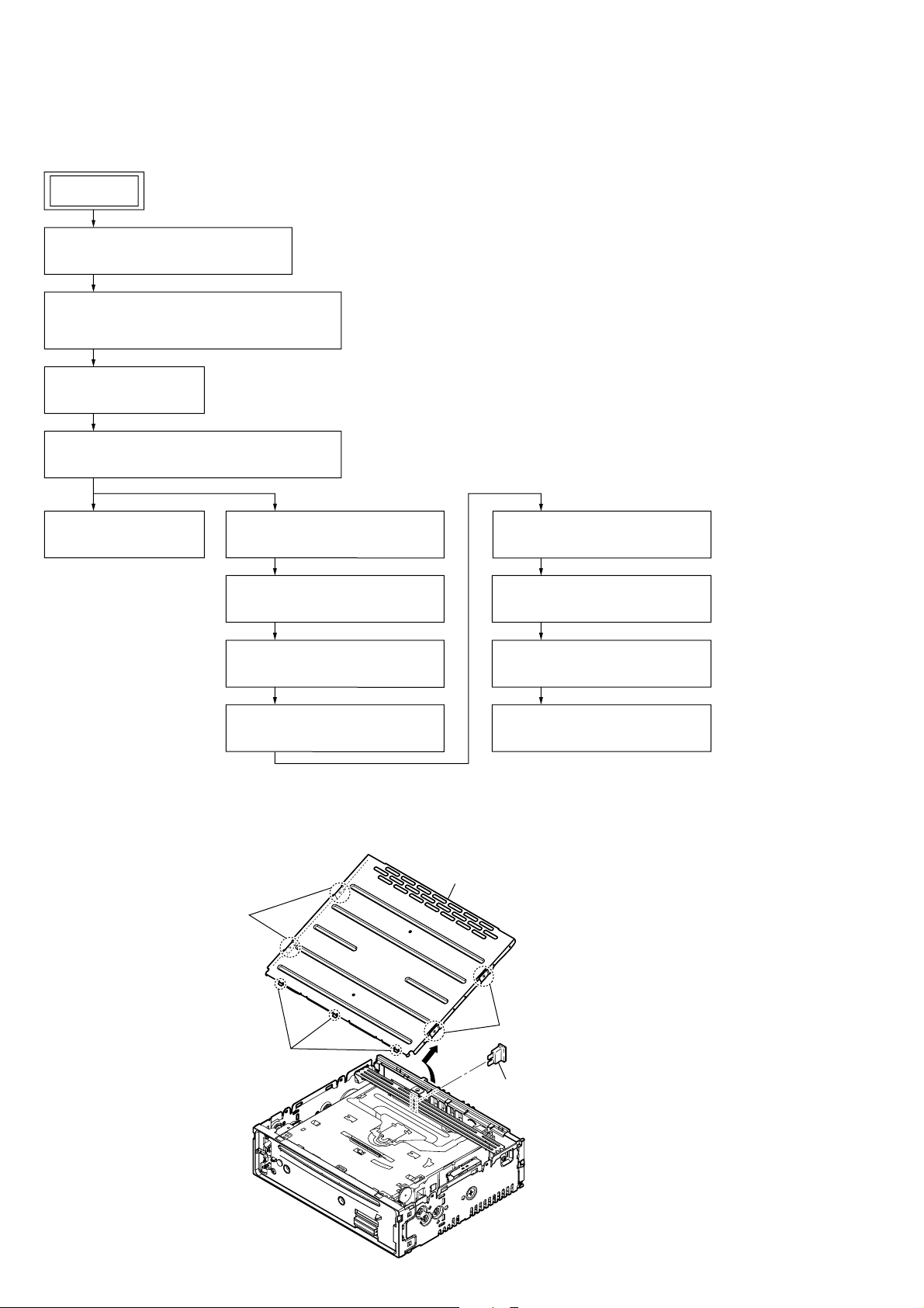
CDX-GT57UPW/GT62UMI/GT570UE/GT570UI/GT570UP/GT574UI/GT620UI/GT626UI
SECTION 3
DISASSEMBLY
• This set can be disassembled in the order shown below.
3-1. DISASSEMBLY FLOW
SET
FRONT PANEL SECTION
Note: Illustration of disassembly is omitted.
3-2. MINI FUSE (BLADE TYPE) (10A/32V) (FU1),
COVER
(Page 18)
3-3. SUB PANEL BLOCK
(Page 19)
3-4. CD MECHANISM DECK (MG-101CA-188)
(Page 19)
3-5. MAIN BOARD
(Page 20)
Note: Follow the disassembly procedure in the numerical order given.
3-6. SERVO BOARD
(Page 20)
3-7. CHASSIS (T) SUB ASSY
(Page 21)
3-8. ROLLER ARM ASSY
(Page 21)
3-9. CHASSIS (OP) ASSY
(Page 22)
3-2. MINI FUSE (BLADE TYPE) (10A/32V) (FU1), COVER
4 cover
2 two bosses
3-10. CHUCKING ARM SUB ASSY
(Page 22)
3-11. SLED MOTOR ASSY
(Page 23)
3-12. OPTICAL PICK-UP SECTION
(Page 24)
3-13. OPTICAL PICK-UP
(Page 24)
18
2 two bosses
3 three claws
1 mini fuse (blade type) (10A/32V)
(FU1)
 Loading...