

Page 1
3-096-840-31 (1)
©
FM/MW/LW
Compact Disc Player
Installation/Connections
Installation/Anschluss
Installation/Connexions
Installazione/Collegamenti
Montage/Aansluitingen
Установка/Подсоединение
CDX-GT50UI
2007 Sony Corporation Printed in Thailand
*1 Note for the antenna (aerial) connecting
If your car antenna (aerial) is an
ISO (International Organization for
Standardization) type, use the supplied
adaptor to connect it. First connect
the car antenna (aerial) to the supplied
adaptor, then connect it to the antenna
(aerial) jack of the master unit.
2
*
RCA pin cord (not supplied)
3
*
AUDIO OUT can be switched SUB or
2
*
1
*
from car antenna (aerial)
von Autoantenne
de l’antenne de la voiture
dall’antenna dell’auto
van een auto-antenne
от автомобильной антенны
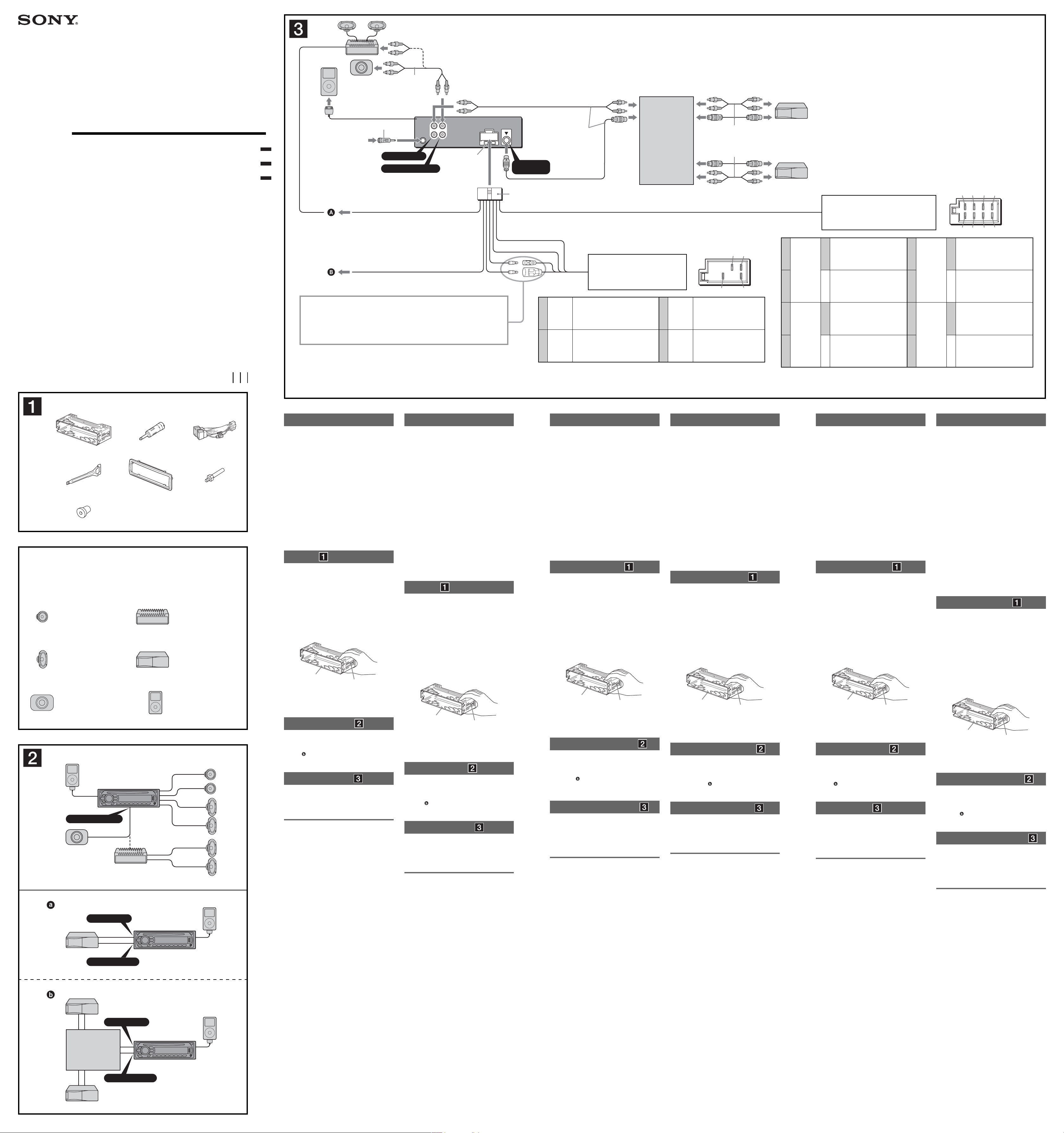
AMP REM
Max. supply current 0.3 A
max. Versorgungsstrom 0,3 A
Courant d’alimentation maximum 0,3 A
Alimentazione massima fornita 0,3 A
Max. voedingsstroom 0,3 A
Макс. сила тока 0,3 А
ATT
See “Power connection diagram” on the reverse side for details.
Näheres dazu fi nden Sie im „Stromanschlussdiagramm“. Blättern Sie dazu bitte um.
Voir le « Schéma de raccordement d’alimentation » au verso pour plus de détails.
Per ulteriori informazioni, vedere “Diagramma dei collegamenti di alimentazione” che si trova
sul retro.
Zie "Voedingsaansluitschema" op de achterkant voor meer details.
Подpобнee cм. в paздeлe “Cxeмa подключeния питaния” нa обpaтной cтоpонe.
BUS AUDIO IN
AUDIO OUT REAR
Blue/white striped
Blauweiß gestreift
Rayé bleu/blanc
Rigato blu e bianco
Blauw/wit gestreept
С синей и белой полосками
AUDIO OUT
BUS
REAR/SUB
IN
Fuse (10 A)
Sicherung (10 A)
Fusible (10 A)
3
Fusibile (10 A)
*
Zekering (10 A)
Предохранитель
(10 А)
REAR. For details, see the supplied
Operating Instructions.
L
R
Light blue
Hellblau
Bleu ciel
Azzurro
Lichtblauw
Голубой
*
*
*
Supplied with XA-C40
Mit dem XA-C40 geliefert
Fourni avec le XA-C40
In dotazione con il modello XA-C40
Geleverd met de XA-C40
Прилагается к модели XA-C40
BUS
CONTROL IN
Yellow
Gelb
Jaune
4
Giallo
Geel
Желтый
Blue
Blau
Bleu
5
Blu
Blauw
Синий
Positions 1, 2, 3, and 6 do not have pins.
An Position 1, 2, 3 und 6 befi nden sich keine Stifte.
Les positions 1, 2, 3 et 6 ne comportent pas de broches.
Le posizioni 1, 2, 3 e 6 non hanno piedini.
De posities 1, 2, 3 en 6 hebben geen pins.
Позиции 1, 2, 3 и 6 не имеют контактных штырьков.
1
Hinweis zum Anschließen der Antenne
Wenn Ihre Autoantenne der ISO-Norm
(Internationale Normungsgemeinschaft)
entspricht, schließen Sie sie mithilfe des
mitgelieferten Adapters an. Verbinden
Sie zuerst die Autoantenne mit dem
mitgelieferten Adapter und verbinden Sie
diesen dann mit der Antennenbuchse
des Hauptgeräts.
2
Cinchkabel (nicht mitgeliefert)
3
AUDIO OUT kann zwischen SUB und
REAR umgeschaltet werden. Näheres
hierzu fi nden Sie in der mitgelieferten
Bedienungsanleitung.
from the car’s power connector
vom Stromanschluss des Fahrzeugs
du connecteur d’alimentation de la voiture
dal connettore di alimentazione dell’auto
van de autovoedingsaansluiting
от автомобильного разъема питания
continuous power supply
permanente Stromversorgung
alimentation continue
alimentazione continua
непрерывное поступление питания
bedieningskabel elektrische antenne
continu voeding
power antenna (aerial) control
Motorantennensteuerung
commande d’antenne électrique
comando dell’antenna elettrica
антенная электрика
1
*
Remarque sur le raccordement de
l’antenne
Si votre antenne de voiture est de type
ISO (Organisation internationale de
normalisation), utilisez l’adaptateur fourni
pour la raccorder. Raccordez d’abord
l’antenne de voiture à l’adaptateur fourni
et, ensuite, à la prise d’antenne de
l’appareil principal.
2
*
Cordon à broche RCA (non fourni)
3
*
AUDIO OUT peut être commuté sur SUB
ou REAR. Pour obtenir plus de détails,
reportez-vous au mode d’emploi fourni.
Source selector
(not supplied)
Signalquellenwähler
(nicht mitgeliefert)
Sélecteur de source
(non fourni)
Selettore di fonte
(non in dotazione)
Bronkeuzeschakelaar
(niet bijgeleverd)
Селектор источника
(не прилагается)
XA-C40
Red
Rot
Rouge
7
Rosso
Rood
Красный
Black
Schwarz
Noir
8
Nero
Zwart
Черный
Supplied with the CD/MD changer
Mit dem CD/MD-Wechsler geliefert
Fourni avec le changeur de CD/MD
In dotazione con il cambia CD/MD
Geleverd met de CD/MD-wisselaar
Прилагается к проигрывателю CD/MD
geschaltete Stromversorgung
alimentazione commutata
коммутируемый питание
57
48
switched power supply
alimentation commutée
geschakelde voeding
ground (earth)
Masse
masse
terra
aarding
земля
1
Nota per il collegamento dell’antenna
*
Se l’antenna dell’auto è di tipo
ISO (International Organization for
Standardization), utilizzare l’adattatore
in dotazione per collegarla. Collegare
prima l’antenna della macchina
all’adattatore in dotazione, quindi
collegarla alla presa dell’antenna
dell’apparecchio principale.
2
*
Cavo a piedini RCA (non in dotazione)
3
*
AUDIO OUT può essere impostato
su SUB o su REAR. Per ulteriori
informazioni, consultare il manuale di
istruzioni per l’uso in dotazione.
1
Purple
Violett
Violet
Viola
Paars
Фиолетовый
2–
3
Gray
Grau
Gris
Grigio
Grijs
Серый
4–
Negative polarity positions 2, 4, 6, and 8 have striped leads.
An den negativ gepolten Positionen 2, 4, 6 und 8 befi nden sich gestreifte Adern.
Les positions de polarité négative 2, 4, 6 et 8 sont dotées de cordons rayés.
Le posizioni a polarità negativa 2, 4, 6 e 8 hanno cavi rigati.
De posities voor negatieve polariteit (2, 4, 6 en 8) hebben gestreepte kabels.
Позиции отрицательной полярности 2, 4, 6 и 8 имеют провода с полосками.
1
*
Opmerking bij de antenne-aansluiting
Indien uw auto is uitgerust met een
antenne van het type ISO (International
Organization for Standardization),
moet u die aansluiten met behulp
van de bijgeleverde adapter . Sluit
eerst de auto-antenne aan op de
bijgeleverde adapter en vervolgens de
antennestekker op het hoofdtoestel.
2
*
TRCA-kabel (niet bijgeleverd)
3
*
AUDIO OUT kan worden ingesteld
op SUB of REAR. Raadpleeg de
bijgeleverde gebruiksaanwijzing voor
meer informatie.
from the car’s speaker connector
vom Lautsprecheranschluss des Fahrzeugs
du connecteur de haut-parleur de la voiture
dal connettore dei diffusori dell’auto
van de autoluidsprekeraansluiting
от автомобильного разъема громкоговорителя
Speaker, Rear, Right
Lautsprecher hinten rechts
Haut-parleur, arrière, droit
+
Diffusore, posteriore, destro
Luidspreker, achter, rechts
Громкоговоритель, задний, правый
Speaker, Rear, Right
Lautsprecher hinten rechts
Haut-parleur, arrière, droit
Diffusore, posteriore, destro
Luidspreker, achter, rechts
Громкоговоритель, задний, правый
Speaker, Front, Right
Lautsprecher vorne rechts
Haut-parleur, avant, droit
+
Diffusore, anteriore, destro
Luidspreker, voor, rechts
Громкоговоритель, передний, правый
Speaker, Front, Right
Lautsprecher vorne rechts
Haut-parleur, avant, droit
Diffusore, anteriore, destro
Luidspreker, voor, rechts
Громкоговоритель, передний, правый
5
6–
7
Зеленый
8–
White
Weiß
Blanc
Bianco
Wit
Белый
Green
Grün
Vert
Verd e
Groen
1
*
Примечание о подсоединении
антенны
Если антенна в Вашем автомобиле
относится к типу, утвержденному
ISO (Международной организацией
по стандартизации), используйте
для ее подсоединения переходник
. Сначала подсоедините
автомобильную антенну к
прилагаемому переходнику, а затем к
антенному гнезду аппарата.
2
*
Шнур с контактными штырьками RCA
(не прилагается)
3
*
Для AUDIO OUT можно выбpaть
положeниe SUB или REAR. Для
полyчeния дополнитeльной
инфоpмaции cм. пpилaгaeмыe
инcтpyкции по экcплyaтaции.
13 57
24 68
Speaker, Front, Left
Lautsprecher vorne links
Haut-parleur, avant, gauche
+
Diffusore, anteriore, sinistro
Luidspreker, voor, links
Громкоговоритель, передний, левый
Speaker, Front, Left
Lautsprecher vorne links
Haut-parleur, avant, gauche
Diffusore, anteriore, sinistro
Luidspreker, voor, links
Громкоговоритель, передний, левый
Speaker, Rear, Left
Lautsprecher hinten links
Haut-parleur, arrière, gauche
+
Diffusore, posteriore, sinistro
Luidspreker, achter, links
Громкоговоритель, задний, левый
Speaker, Rear, Left
Lautsprecher hinten links
Haut-parleur, arrière, gauche
Diffusore, posteriore, sinistro
Luidspreker, achter, links
Громкоговоритель, задний, левый
× 2
Equipment used in illustrations (not supplied)
In Abbildungen dargestellte Geräte (nicht mitgeliefert)
Appareils utilisés dans les illustrations (non fournis)
Apparecchiatura utilizzata nelle illustrazioni (non in dotazione)
Apparatuur gebruikt in de afbeeldingen (niet bijgeleverd)
Аппаратура, фигурирующая в иллюстрациях (не прилагается)
Front speaker
Frontlautsprecher
Haut-parleur avant
Diffusore anteriore
Voorluidspreker
Передний громкоговоритель
Rear speaker
Hecklautsprecher
Haut-parleur arrière
Diffusore posteriore
Achterluidspreker
Задний громкоговоритель
Active subwoofer
Aktiver Tiefsttonlautsprecher
Caisson de graves actif
Subwoofer attivo
Actieve subwoofer
Aктивный низкочacтотный
гpомкоговоpитeль
iPod
Power amplifi er
Endverstärker
Amplifi cateur de puissance
Amplifi catore di potenza
Versterker
Усилитель мощности
CD/MD changer
CD/MD-Wechsler
Changeur de CD/MD
Cambia CD/MD
CD/MD-wisselaar
Проигрыватель CD/MD
iPod
A
AUDIO OUT REAR*
* AUDIO OUT SUB/REAR
B
BUS AUDIO IN
BUS CONTROL IN
BUS AUDIO IN
Source selector*
Signalquellenwähler*
Sélecteur de source*
Selettore di fonte*
Bronkeuzeschakelaar*
Селектор источника*
XA-C40
BUS CONTROL IN
* not supplied
nicht mitgeliefert
non fourni
non in dotazione
niet bijgeleverd
не прилагается
iPod
iPod
Cautions
• This unit is designed for negative ground (earth) 12 V
DC operation only.
• Do not get the leads under a screw, or caught in moving
parts (e.g. seat railing).
• Before making connections, turn the car ignition off to
avoid short circuits.
• Connect the power connecting lead to the unit and
speakers before connecting it to the auxiliary power
connector.
• Run all ground (earth) leads to a common
ground (earth) point.
• Be sure to insulate any loose unconnected leads with
electrical tape for safety.
Notes on the power supply lead (yellow)
• When connecting this unit in combination with other
stereo components, the connected car circuit’s rating
must be higher than the sum of each component’s fuse.
• When no car circuits are rated high enough, connect
the unit directly to the battery.
iPod is a trademark of Apple Computer, Inc., registered
in the U.S. and other countries.
Parts Iist
• The numbers in the list are keyed to those in the
instructions.
• The bracket and the protection collar are
attached to the unit before shipping. Before mounting
the unit, use the release keys to remove the bracket
and the protection collar from the unit. For
details, see “Removing the protection collar and the
bracket ()” on the reverse side of the sheet.
• Keep the release keys for future use as they
are also necessary if you remove the unit from
your car.
Caution
Handle the bracket carefully to avoid injuring your
fi ngers.
Catch
Note
Before installing, make sure that the catches on both sides of
the bracket are bent inwards 2 mm (
straight or bent outwards, the unit will not be installed securely
and may spring out.
3
/32 in). If the catches are
Connection example
Notes (-A)
• Be sure to connect the ground (earth) lead before connecting
the amplifi er.
• The alarm will only sound if the built-in amplifi er is used.
Tip (-B-
For connecting two or more CD/MD changers, the source
selector XA-C40 (not supplied) is necessary.
)
Connection diagram
To AMP REMOTE IN of an optional power
amplifi er
This connection is only for amplifi ers. Connecting any other
system may damage the unit.
To the interface cable of a car telephone
Warning
If you have a power antenna (aerial) without a relay box,
connecting this unit with the supplied power connecting
lead may damage the antenna (aerial).
Notes on the control and power suppy leads
• The power antenna (aerial) control lead (blue) supplies +12 V
DC when you turn on the tuner, or when you activate the AF
(Alternative Frequency) or TA (Traffi c Announcement) function.
• When your car has built-in FM/MW/LW antenna (aerial) in the
rear/side glass, connect the power antenna (aerial) control
lead (blue) or the accessory power supply lead (red) to the
power terminal of the existing antenna (aerial) booster. For
details, consult your dealer.
• A power antenna (aerial) without a relay box cannot be used
with this unit.
Memory hold connection
When the yellow power supply lead is connected, power will
always be supplied to the memory circuit even when the ignition
switch is turned off.
Notes on speaker connection
• Before connecting the speakers, turn the unit off.
• Use speakers with an impedance of 4 to 8 ohms, and with
adequate power handling capacities to avoid its damage.
• Do not connect the speaker terminals to the car chassis, or
connect the terminals of the right speakers with those of the
left speaker.
• Do not connect the ground (earth) lead of this unit to the
negative (–) terminal of the speaker.
• Do not attempt to connect the speakers in parallel.
• Connect only passive speakers. Connecting active speakers
(with built-in amplifi ers) to the speaker terminals may damage
the unit.
• To avoid a malfunction, do not use the built-in speaker leads
installed in your car if the unit shares a common negative (–)
lead for the right and left speakers.
• Do not connect the unit’s speaker leads to each other.
Notes on connection
• If speaker and amplifi er are not connected correctly, “FAILURE”
appears in the display. In this case, make sure the speaker and
amplifi er are connected correctly.
• An another iPod cannot be connected using the XA-110IP.
Warnhinweise
• Dieses Gerät ist ausschließlich für den Betrieb bei 12 V
Gleichstrom (negative Erdung) bestimmt.
• Achten Sie darauf, dass die Kabel nicht unter einer
Schraube oder zwischen beweglichen Teilen wie
z. B. in einer Sitzschiene eingeklemmt werden.
• Schalten Sie, bevor Sie irgendwelche Anschlüsse
vornehmen, die Zündung des Fahrzeugs aus, um
Kurzschlüsse zu vermeiden.
• Verbinden Sie das Stromversorgungskabel mit dem
Gerät und den Lautsprechern, bevor Sie es mit dem
Hilfsstromanschluss verbinden.
• Schließen Sie alle Erdungskabel an einen
gemeinsamen Massepunkt an.
• Aus Sicherheitsgründen müssen alle losen, nicht
angeschlossenen Drähte mit Isolierband abgeklebt
werden.
Hinweise zum Stromversorgungskabel (gelb)
• Wenn Sie dieses Gerät zusammen mit anderen
Stereokomponenten anschließen, muss der
Autostromkreis, an den die Geräte angeschlossen sind,
eine höhere Leistung aufweisen als die Summe der
Sicherungen der einzelnen Komponenten.
• Wenn kein Autostromkreis eine so hohe Leistung
aufweist, schließen Sie das Gerät direkt an die Batterie
an.
iPod ist ein in den USA und anderen Ländern
eingetragenes Markenzeichen der Apple Computer, Inc.
Teileliste
• Die Nummern in der Liste sind dieselben wie im
Erläuterungstext.
• Die Halterung und die Schutzumrandung werden
vor dem Ausliefern am Gerät angebracht. Bevor Sie
das Gerät montieren, nehmen Sie die Halterung und
die Schutzumrandung mithilfe der Löseschlüssel
bitte vom Gerät ab. Einzelheiten dazu fi nden Sie unter
„Abnehmen der Schutzumrandung und der Halterung
()“ auf der Rückseite dieses Blattes.
• Bewahren Sie die Löseschlüssel für den
späteren Gebrauch auf. Sie werden
z. B. benötigt, wenn Sie das Gerät aus dem
Fahrzeug ausbauen wollen.
Vorsicht
Seien Sie beim Umgang mit der Halterung vorsichtig,
damit Sie sich nicht die Hände verletzen.
Verriegelung
Hinweis
Vergewissern Sie sich vor dem Installieren, dass die
Verriegelungen an beiden Seiten der Halterung um 2 mm
nach innen gebogen sind. Wenn die Verriegelungen gerade oder
nach außen gebogen sind, lässt sich das Gerät nicht sicher
installieren und kann herausspringen.
Anschlussbeispiel
Hinweise (-A)
• Schließen Sie unbedingt zuerst das Massekabel an, bevor Sie
den Verstärker anschließen.
• Der Warnton wird nur ausgegeben, wenn der integrierte
Verstärker verwendet wird.
Tipp (-B-
Zum Anschließen von zwei oder mehr CD/MD-Wechslern wird
der Signalquellenwähler XA-C40 (nicht mitgeliefert) benötigt.
)
Anschlussdiagramm
An AMP REMOTE IN des gesondert
erhältlichen Endverstärkers
Dieser Anschluss ist ausschließlich für Verstärker gedacht.
Schließen Sie nichts anderes daran an. Andernfalls kann
das Gerät beschädigt werden.
An Schnittstellenkabel eines Autotelefons
Warnung
Wenn Sie eine Motorantenne ohne Relaiskästchen
verwenden, kann durch Anschließen dieses Geräts mit
dem mitgelieferten Stromversorgungskabel die
Antenne beschädigt werden.
Hinweise zu den Steuer- und Stromversorgungsleitungen
• Die Motorantennen-Steuerleitung (blau) liefert +12 V
Gleichstrom, wenn Sie den Tuner einschalten oder die
AF- (Alternativfrequenzsuche) oder die TA-Funktion
(Verkehrsdurchsagen) aktivieren.
• Wenn das Fahrzeug mit einer in der Heck-/
Seitenfensterscheibe integrierten FM (UKW)/MW/LWAntenne ausgestattet ist, schließen Sie die MotorantennenSteuerleitung (blau) oder die Zubehörstromversorgungsleitung
(rot) an den Stromversorgungsanschluss des vorhandenen
Antennenverstärkers an. Näheres dazu erfahren Sie bei Ihrem
Händler.
• Es kann nur eine Motorantenne mit Relaiskästchen
angeschlossen werden.
Stromversorgung des Speichers
Wenn die gelbe Stromversorgungsleitung angeschlossen ist,
wird der Speicher stets (auch bei ausgeschalteter Zündung) mit
Strom versorgt.
Hinweise zum Lautsprecheranschluss
• Schalten Sie das Gerät aus, bevor Sie die Lautsprecher
anschließen.
•
Verwenden Sie Lautsprecher mit einer Impedanz zwischen 4 und
8 Ohm und ausreichender Belastbarkeit. Ansonsten können die
Lautsprecher beschädigt werden.
• Verbinden Sie die Lautsprecheranschlüsse nicht mit dem
Wagenchassis und verbinden Sie auch nicht die Anschlüsse
des rechten mit denen des linken Lautsprechers.
• Verbinden Sie die Masseleitung dieses Geräts nicht mit dem
negativen (–) Lautsprecheranschluss.
•
Versuchen Sie nicht, Lautsprecher parallel anzuschließen.
• An die Lautsprecheranschlüsse dieses Geräts dürfen nur
Passivlautsprecher angeschlossen werden. Schließen Sie
keine Aktivlautsprecher (Lautsprecher mit eingebauten
Verstärkern) an, da das Gerät sonst beschädigt werden
könnte.
• Um Fehlfunktionen zu vermeiden, verwenden Sie nicht die
im Fahrzeug installierten, integrierten Lautsprecherleitungen,
wenn am Ende eine gemeinsame negative (–) Leitung für den
rechten und den linken Lautsprecher verwendet wird.
• Verbinden Sie nicht die Lautsprecherkabel des Geräts
miteinander.
Hinweise zum Anschließen
• Wenn Lautsprecher und Verstärker nicht richtig angeschlossen
sind, erscheint „FAILURE“ im Display. Vergewissern Sie sich
in diesem Fall, dass Lautsprecher und Verstärker richtig
angeschlossen sind.
• Sie können über den XA-110IP keinen weiteren iPod
anschließen.
Précautions
• Cet appareil est conçu pour fonctionner sur un courant
continu de 12 V avec masse négative.
• Evitez de coincer les câbles sous des vis ou dans des
pièces mobiles (par exemple, armature de siège).
• Avant d’effectuer des raccordements, coupez le moteur
pour éviter les courts-circuits.
• Branchez le câble d’alimention sur l’appareil et les
haut-parleurs avant de le brancher sur le connecteur
d’alimentation auxiliaire.
• Rassemblez tous les câbles de mise à la
masse en un point de masse commun.
• Veillez à isoler tout câble non connecté avec du ruban
isolant.
Remarques sur le câble d’alimentation (jaune)
• Lorsque cet appareil est raccordé à d’autres
équipements stéréo, la valeur nominale des circuits du
véhicule raccordés doit être supérieure à la somme des
fusibles de chaque élément.
• Si aucun circuit de la voiture n’est assez puissant,
raccordez directement l’appareil à la batterie.
iPod est une marque commerciale de Apple Computer,
Inc. déposée aux États-Unis et dans d’autres pays/
régions.
Liste des composants
• Les numéros de la liste correspondent à ceux des
instructions.
• Le support et le tour de protection sont fi xés à
l’appareil en usine. Avant le montage de l’appareil,
utilisez les clés de déblocage pour détacher le
support et le tour de protection de l’appareil.
Pour de plus amples informations, reportez-vous à la
section « Retrait du tour de protection et du support
() » au verso de la feuille.
• Conservez les clés de déblocage pour
une utilisation ultérieure car vous en aurez
également besoin pour retirer l’appareil de
votre véhicule.
Avertissement
Manipulez le support avec soin pour éviter de vous
blesser aux doigts.
Loquet
Remarque
Avant l’installation, assurez-vous que les loquets des deux côtés
du support sont bien pliés de 2 mm vers l’intérieur. Si les
loquets sont droits ou pliés vers l’extérieur, l’appareil ne peut pas
être fi xé solidement et peut se détacher.
Exemple de raccordement
Remarques (-A)
• Raccordez d’abord le câble de mise à la masse avant de
raccorder l’amplifi cateur.
• L’alarme est émise uniquement lorsque l’amplifi cateur intégré
est utilisé.
Conseil (-B-
Dans le cas du raccordement de deux changeurs de CD/MD
ou plus, le sélecteur de source XA-C40 (non fourni) est
indispensable.
)
Schémas de raccordement
Vers AMP REMOTE IN d’un amplifi cateur de
puissance en option
Ce raccordement est possible uniquement pour les
amplifi cateurs. Le raccordement à tout autre système peut
endommager l’appareil.
Vers le cordon de liaison d’un téléphone de
voiture
Avertissement
Si vous disposez d’une antenne électrique sans boîtier
de relais, le branchement de cet appareil au moyen du
cordon d’alimentation fourni risque d’endommager
l’antenne.
Remarques sur les câbles de commande et d’alimentation
• Le câble de commande (bleu) fournit du courant continu de
+12 V lorsque vous mettez le tuner sous tension ou lorsque
vous activez la fonction AF (fréquence alternative) ou TA
(messages de radioguidage).
• Si votre voiture est équipée d’une antenne FM/MW (PO)/LW
(GO) intégrée dans la vitre arrière/latérale, raccordez le
câble de commande (bleu) ou le câble d’alimentation des
accessoires (rouge) à la borne d’alimentation de l’amplifi cateur
d’antenne existant. Pour plus de détails, consultez votre
revendeur.
• Une antenne électrique sans boîtier de relais ne peut pas être
utilisée avec cet appareil.
Raccordement pour la conservation de la mémoire
Lorsque le câble d’alimentation jaune est connecté, le circuit
de la mémoire est alimenté en permanence même si la clé de
contact est en position d’arrêt.
Remarques sur le raccordement des haut-parleurs
• Avant de raccorder les haut-parleurs, mettez l’appareil hors
tension.
• Utilisez des haut-parleurs ayant une impédance de 4 à 8 ohms
et une capacité adéquate sous peine de les endommager.
• Ne raccordez pas les bornes du système de haut-parleurs au
châssis de la voiture et ne connectez pas les bornes du hautparleur droit à celles du haut-parleur gauche.
• Ne raccordez pas le câble de mise à la masse de cet appareil
à la borne négative (–) du haut-parleur.
• Ne tentez pas de raccorder les haut-parleurs en parallèle.
• Raccordez uniquement des haut-parleurs passifs. Le
raccordement de haut-parleurs actifs (avec des amplifi cateurs
intégrés) aux bornes des haut-parleurs pourrait endommager
l’appareil.
• Pour éviter tout problème de fonctionnement, n’utilisez pas les
câbles des haut-parleurs intégrés installés dans votre voiture
si l’appareil dispose d’un câble négatif commun (–) pour les
haut-parleurs droit et gauche.
• Ne raccordez pas entre eux les cordons des haut-parleurs de
l’appareil.
Remarques sur le raccordement
• Si les haut-parleurs et l’amplifi cateur ne sont pas raccordés
correctement, le message « FAILURE » s’affi che. Dans ce
cas, assurez-vous que les haut-parleurs et l’amplifi cateur sont
raccordés correctement.
• Il est impossible de raccorder un autre iPod à l’aide du XA110IP.
Attenzione
• Questo apparecchio è stato progettato per l’uso solo a
12 V CC con massa negativa.
• Evitare che i cavi rimangano bloccati da una vite o
incastrati nelle parti mobili (ad esempio nelle guide
scorrevoli dei sedili).
• Prima di effettuare i collegamenti, spegnere il motore
dell’automobile onde evitare di causare cortocircuiti.
• Collegare il cavo di alimentazione all’apparecchio
e ai diffusori prima di collegarlo al connettore di
alimentazione ausiliaria.
• Portare tutti i cavi di messa a terra a un punto
di massa comune.
• Per sicurezza, assicurarsi di isolare qualsiasi cavo non
collegato utilizzando del nastro adesivo.
Note sul cavo di alimentazione (giallo)
• Se questo apparecchio viene collegato in combinazione
con altri componenti stereo, la potenza nominale
dei circuiti dell’automobile deve essere superiore a
quella prodotta dalla somma dei fusibili di ciascun
componente.
• Se la potenza nominale dei circuiti dell’automobile non
è suffi ciente, collegare l’apparecchio direttamente alla
batteria.
iPod è un marchio di fabbrica di Apple Computer, Inc.,
registrato negli Stati Uniti e in altri paesi.
Elenco dei componenti
• I numeri nell’elenco corrispondono a quelli riportati
nelle istruzioni.
• La staffa e la cornice protettiva vengono
applicati all’unità in fabbrica. Prima di installare
l’unità, utilizzare le chiavette di rilascio per
rimuovere la staffa e la cornice protettiva
dall’apparecchio. Per ulteriori informazioni, vedere
“Rimozione della staffa e della cornice protettiva ()”
sul lato opposto del foglio.
• Conservare le chiavette di rilascio per un
uso futuro in quanto sono necessarie per
rimuovere l’unità dall’auto.
Attenzione
Maneggiare la staffa con cautela per evitare di ferirsi
le mani.
Fermo
Nota
Prima di installare l’unità, accertarsi di ripiegare i fermi presenti
su entrambi i lati della staffa verso l’interno di 2 mm. Se i fermi
sono diritti o ripiegati verso l’esterno, l’apparecchio non verrà
installato in modo sicuro e potrebbe fuoriuscire.
Esempio di collegamento
Note (-A)
• Assicurarsi di collegare il cavo di terra prima di collegare
l’apparecchio all’amplifi catore.
• L’allarme viene emesso solo se è in uso l’amplifi catore
incorporato.
Suggerimento (-B-
Per collegare due o più cambia CD/MD, occorre utilizzare il
selettore di fonte XA-C40 (non in dotazione).
)
Schema di collegamento
A AMP REMOTE IN di un amplifi catore di
potenza opzionale
Questo collegamento è riservato esclusivamente agli
amplifi catori. Non collegare un tipo di sistema diverso onde
evitare di causare danni all’apparecchio.
Al cavo di interfaccia di un telefono per auto
Avvertenza
Quando si collega l’apparecchio con il cavo di
alimentazione in dotazione , si potrebbe danneggiare
l’antenna elettrica se questa non dispone di scatola a relè.
Note sui cavi di controllo e di alimentazione
• Il cavo (blu) di controllo dell’antenna elettrica fornisce
alimentazione pari a +12 V CC quando si attiva il
sintonizzatore oppure la funzione AF (frequenza alternativa) o
TA (notiziario sul traffi co).
• Se l’automobile è dotata di antenna FM/MW/LW incorporata
nel vetro posteriore/laterale, collegare il cavo (blu) di
controllo dell’antenna elettrica o il cavo (rosso) di ingresso
dell’alimentazione ausiliaria al terminale di alimentazione
dell’amplifi catore di potenza dell’antenna esistente. Per ulteriori
informazioni, consultare il proprio fornitore.
• Non è possibile usare un’antenna elettrica senza scatola a relè
con questo apparecchio.
Collegamento per la conservazione della memoria
Quando il cavo di alimentazione giallo è collegato, viene sempre
fornita alimentazione al circuito di memoria anche quando
l’interruttore di accensione è spento.
Note sul collegamento dei diffusori
• Prima di collegare i diffusori spegnere l’apparecchio.
• Usare diffusori di impedenza compresa tra 4 e 8 ohm e con
capacità di potenza adeguata, altrimenti i diffusori potrebbero
venire danneggiati.
• Non collegare i terminali del sistema diffusori al telaio dell’auto
e non collegare i terminali del diffusore destro a quelli del
diffusore sinistro.
• Non collegare il cavo di terra di questo apparecchio al
terminale negativo (–) del diffusore.
• Non collegare i diffusori in parallelo.
• Assicurarsi di collegare soltanto diffusori passivi, poiché
il collegamento di diffusori attivi, dotati di amplifi catori
incorporati, ai terminali dei diffusori potrebbe danneggiare
l’apparecchio.
• Per evitare problemi di funzionamento, non utilizzare i cavi dei
diffusori incorporati installati nell’automobile se l’apparecchio
condivide un cavo comune negativo (–) per i diffusori destro e
sinistro.
• Non collegare fra loro i cavi dei diffusori dell’apparecchio.
Note sui collegamenti
• Se l’amplifi catore e il diffusore non sono collegati
correttamente, “FAILURE” viene visualizzato nel display. In tal
caso, accertarsi che l’amplifi catore e il diffusore siano collegati
correttamente.
• Non è possibile collegare un altro iPod utilizzando XA-110IP.
Let op
• Dit apparaat is ontworpen voor gebruik op een autoaccu van 12 V gelijkstroom, negatieve aarde.
• Zorg ervoor dat de kabels niet onder een schroef
of tussen bewegende onderdelen (b.v. zetelrail)
terechtkomen.
• Voordat u de aansluitingen maakt, moet u het contact
uitzetten om kortsluiting te vermijden.
• Sluit de voedingskabel aan op het apparaat
en de luidsprekers voordat u deze aansluit op de
hulpvoedingsaansluiting.
• Sluit alle aardingskabels op een
gemeenschappelijk aardpunt aan.
• Voorzie niet aangesloten kabels om veiligheidsredenen
altijd van isolatietape.
Opmerkingen bij de voedingskabel (geel)
• Wanneer u dit apparaat aansluit samen met andere
componenten, moet het vermogen van de aangesloten
autostroomkring groter zijn dan de som van de
zekeringen van elke component afzonderlijk.
• Wanneer het vermogen ontoereikend is, moet u het
apparaat rechtstreeks aansluiten op de accu.
iPod is een handelsmerk van Apple Computer, Inc.,
gedeponeerd in de Verenigde Staten en andere landen.
Onderdelenlijst enlijst
• De nummers in de afbeelding verwijzen naar die in de
instructies.
• De beugel en de beschermende rand worden
bevestigd op het apparaat voordat dit wordt
verzonden. Voordat u het apparaat plaatst, moet u de
ontgrendelingssleutels gebruiken om de beugel
en de beschermende rand te verwijderen van het
apparaat. Zie "De beschermende rand en de beugel
verwijderen ()" op de achterkant van dit vel voor
meer informatie.
• Bewaar de ontgrendelingssleutels voor
toekomstig gebruik omdat u deze ook
nodig hebt om het apparaat uit de auto te
verwijderen.
Let op
Houd de beugel voorzichtig vast zodat u uw vingers
niet verwondt.
Greep
Opmerking
Voordat u het apparaat installeert, moet u de grepen aan beide
zijden van de beugel 2 mm naar binnen buigen. Als de grepen
recht zijn of naar buiten gebogen, kan het apparaat niet goed
worden bevestigd en kan dit losschieten.
Voorbeeldaansluiting
Opmerkingen (-A)
• Sluit eerst de aardingskabel aan voordat u de versterker
aansluit.
• U hoort de pieptoon alleen als de ingebouwde versterker wordt
gebruikt.
Tip (-B-
Om twee of meer CD/MD-wisselaars aan te sluiten, hebt u de
bronkeuzeschakelaar XA-C40 (niet bijgeleverd) nodig.
)
Aansluitschema
Naar AMP REMOTE IN van een optionele
versterker
Deze aansluiting is alleen bedoeld voor versterkers. Door
een ander systeem aan te sluiten kan het apparaat worden
beschadigd.
Naar het interface-snoer van een
autotelefoon
Waarschuwing
Indien u een elektrische antenne hebt zonder relaiskast,
kan het aansluiten van dit apparaat met de bijgeleverde
voedingskabel de antenne beschadigen.
Opmerkingen over de bedienings- en voedingskabels
• De bedieningskabel elektrische antenne (blauw) levert
+12 V gelijkstroom wanneer u de tuner inschakelt of de AF
(alternatieve frequenties) of TA (verkeersinformatie) functie
activeert.
• Wanneer uw auto is uitgerust met een FM/MW/LW-antenne
in de achterruit/zijruit, moet u de bedieningskabel elektrische
antenne (blauw) of de voedingskabel van de accessoires
(rood) aansluiten op de voedingsingang van de bestaande
antenneversterker. Raadpleeg uw dealer voor meer details.
• Met dit apparaat is het niet mogelijk een elektrische antenne
zonder relaiskast te gebruiken.
Instandhouden van het geheugen
Zolang de gele voedingskabel is aangesloten, blijft de
stroomvoorziening van het geheugen intact, ook wanneer de
contactschakelaar van de auto wordt uitgeschakeld.
Opmerkingen betreffende het aansluiten van de luidsprekers
• Zorg dat het apparaat is uitgeschakeld, alvorens de
luidsprekers aan te sluiten.
• Gebruik luidsprekers met een impedantie van 4 tot 8 Ohm
en let op dat die het vermogen van de versterker kunnen
verwerken. Als u dit niet doet, kunnen de luidsprekers ernstig
beschadigd raken.
• Verbind in geen geval de aardingskabel van de luidsprekers
met het chassis van de auto en sluit de aansluitingen van de
rechter- en linkerluidspreker niet op elkaar aan.
• Verbind de aarddraad van dit apparaat niet met de negatieve
(–) aansluiting van de luidspreker.
• Probeer nooit de luidsprekers parallel aan te sluiten.
• Sluit geen actieve luidsprekers (met ingebouwde versterkers)
aan op de luidsprekeraansluiting van dit apparaat. Dit zal
leiden tot beschadiging van de actieve luidsprekers. Sluit dus
altijd uitsluitend luidsprekers zonder ingebouwde versterker
aan.
• Om defecten te vermijden mag u de bestaande
luidsprekerbedrading in uw auto niet gebruiken wanneer er een
gemeenschappelijke negatieve (–) kabel is voor de rechter- en
linkerluidsprekers.
• Verbind de luidsprekerkabels niet met elkaar.
Opmerkingen over aansluiten
• Als de luidspreker en versterker niet goed zijn aangesloten,
wordt "FAILURE" in het display weergegeven. In dit geval
moet u zorgen dat de luidspreker en versterker correct zijn
aangesloten.
• Een iPod kan niet worden aangesloten met de XA-110IP.
Внимание
•
Данный аппарат для подключения только
к аккумулятору 12 В постоянного тока с
отpицaтeльным заземлением.
•
He допycкaйтe попaдaния пpоводов под винты или
мeждy подвижными дeтaлями (нaпpимep, мeждy
нaпpaвляющими cидeний).
•
Пepeд выполнeниeм cоeдинeния выключитe
зaжигaниe aвтомобиля во избeжaниe коpоткого
зaмыкaния.
•
Сначала подсоедините провод питания к аппарату
и громкоговорителям, а затем к контактам внешнего
источника питания.
•
Подведите все провода заземления к одной
точке заземления.
•
B цeляx бeзопacноcти обязaтeльно изолиpyйтe вce
cвободныe нeподcоeдинeнныe пpоводa изоляционной
лeнтой.
Пpимeчaния отноcитeльно провода питaния
(жeлтого)
Пpи подключeнии этого аппарата вмecтe c дpyгими
•
cтepeокомпонeнтaми номинaльноe знaчeниe
cилы токa в контype питaния aвтомобиля должно
пpeвышaть cyммapноe знaчeниe cилы токa,
yкaзaнноe нa пpeдоxpaнитeляx вcex компонeнтов.
•
Ecли номинaльноe знaчeниe cилы токa в контype
питaния aвтомобиля нe доcтaточно выcокоe,
подcоeдинитe аппарат нaпpямyю к aккyмyлятоpy.
iPod является товарным знаком компании Apple
Computer, Inc., зарегистрированным в США и других
странах.
Перечень деталей
•
Цифpы в cпиcкe соответствуют цифрам,
упоминаемым далее в данной инструкции.
•
Пpи поcтaвкe кpонштeйн и зaщитнaя мaнжeтa
пpикpeпляютcя к аппарату. Пepeд монтaжом cнимитe
кpонштeйн
c помощью ключeй для дeмонтaжa
инфоpмaцию cм. в paздeлe “Cнятиe зaщитной
мaнжeты и кpонштeйнa (
лиcтa.
•
Cоxpaнитe ключи для дeмонтaжa для
и зaщитнyю мaнжeтy c аппарата
. Подpобнyю
)” нa обpaтной cтоpонe
иcпользовaния в бyдyщeм, тaк кaк они тaкжe
потpeбyютcя пpи дeмонтaжe аппарата из
мaшины.
Bнимaниe
Обращайтесь с кpонштeйном осторожно, чтобы не
повредить пальцы.
Фикcaтоp
Пpимeчaниe
Пepeд ycтaновкой yбeдитecь, что фикcaтоpы по обeим cтоpонaм
кpонштeйнa
нaxодятcя в пpямом положeнии или выгнyты наружу, аппарат не
удастся надежно установить, и он может выпасть.
зaгнyты внyтpь нa 2 мм. Ecли фикcaтоpы
Пример подсоединения
Примечания (-A)
•
Прежде чем подключать аппарат к усилителю, обязательно
подсоедините провод заземления.
•
Звуковой сигнал будет воспроизводиться только в том случае,
если используется встроенный усилитель.
Совет (-B-
Пpи подcоeдинeнии двyx или болee проигрывателей CD/MD
потpeбyeтcя ceлeктоp иcточникa XA-C40 (нe пpилaгaeтcя).
)
Схема подсоединения
Подключeниe к вxодy AMP REMOTE IN
дополнитeльного ycилитeля мощноcти
Этот вapиaнт подключeния иcпользyeтcя только для
ycилитeлeй. Подключeниe любой дpyгой cиcтeмы можeт
пpивecти к повpeждeнию аппарата.
К интepфeйcномy кaбeлю aвтомобильного
тeлeфонa
Предостережение
Если Вы используете антенну с электрическим
приводом без релейного блока, подсоединение этого
аппарата посредством прилагаемого провода питания
может привести к повреждению антенны.
О проводах управления и питания
•
При включении тюнера, а также использовании функции AF
(Альтернативные частоты) или TA (Сообщения о текущей
ситуации на дорогах) по проводу питaния пpиeмной aнтeнны
(cинeмy) подaeтcя нaпpяжeниe +12 B поcтоянного токa.
•
Ecли нa зaднeм/боковом cтeклe aвтомобиля ycтaновлeнa
вcтpоeннaя aнтeннa диaпaзонa FM/MW/LW, подcоeдинитe
пpовод питaния пpиeмной aнтeнны (cиний) или пpовод
питaния аппарата (кpacный) к клeммe питaния cyщecтвyющeго
ycилитeля aнтeнны. Чтобы полyчить дополнитeльныe cвeдeния,
обpaтитecь к cвоeмy дилepy.
•
Антенна с электрическим приводом, не снабженная релейным
блоком, с этим аппаратом использоваться не может.
Подсоединение для поддержки памяти
Когда к аппарату подсоединен желтый электрический провод, блок
памяти будет постоянно получать питание даже при выключенном
зажигании.
Примечания относительно подсоединения
громкоговорителей
•
Прежде чем подсоединять громкоговорители, выключите аппарат.
•
Используйте громкоговорители с полным сопротивлением 4 - 8
Ом, обладающие способностью принимать достаточно мощный
сигнал. В противном случае они могут быть повреждены.
•
Не подсоединяйте контактные гнезда громкоговорителей
к шасси автомобиля и не соединяйте гнезда правого
громкоговорителя с гнездами левого.
•
He подключaйтe пpовод зaзeмлeния аппарата к отpицaтeльномy
(–) контaктy гpомкоговоpитeля.
•
Не пытайтесь подсоединить громкоговорители параллельно.
•
Подсоединять можно только пассивные громкоговорители.
Подсоединение активных громкоговорителей (со встроенным
усилителем) к гнездам для громкоговорителей может привести
к повреждению аппарата.
•
Bо избeжaниe нeпpaвильной paботы аппарата нe иcпользyйтe
вcтpоeнныe в aвтомобиль пpоводa гpомкоговоpитeлeй, ecли
используется общий отpицaтeльный пpовод (–) для пpaвого и
лeвого гpомкоговоpитeлeй.
•
He подсоединяйте друг к другу пpоводa гpомокоговоpитeлeй
аппарата.
Примечания отноcитeльно подcоeдинeния
•
Ecли гpомкоговоpитeль и ycилитeль подcоeдинeны нeпpaвильно,
нa диcплee отобpaзитcя нaдпиcь “FAILURE”. B этом cлyчae
пpовepьтe пpaвильноcть подcоeдинeния гpомкоговоpитeля и
ycилитeля.
•
Невозможно подключить еще одно устройство iPod с помощью
XA-110IP.
Page 2
1
A
1
Orient the release key correctly.
Richten Sie den Löseschlüssel korrekt aus.
Orientez correctement la clé de déblocage.
Orientare la chiavetta di rilascio nel modo corretto.
Plaats de ontgrendelingssleutel op de juiste manier.
Дepжитe ключ для дeмонтaжa нaдлeжaщим обpaзом.
23
182 m
m
53 m
m
Claws
Klammern
Griffes
Morsetti
Klemhaken
Bыcтyпы
2
Dashboard
Armaturenbrett
Tableau de bord
Cruscotto
Dashboard
Приборная пaнeль
Face the hook inwards.
Der Haken muss nach innen weisen.
Tournez le crochet vers l’intérieur.
Con il gancetto rivolto verso l’interno.
Het haakje moet naar binnen wijzen.
Haпpaвьтe кpючок внyтpь.
B
Fire wall
Motorraumtrennwand
Paroi ignifuge
Parete tagliafi amma
Brandschot
Огнеупорная перегородка
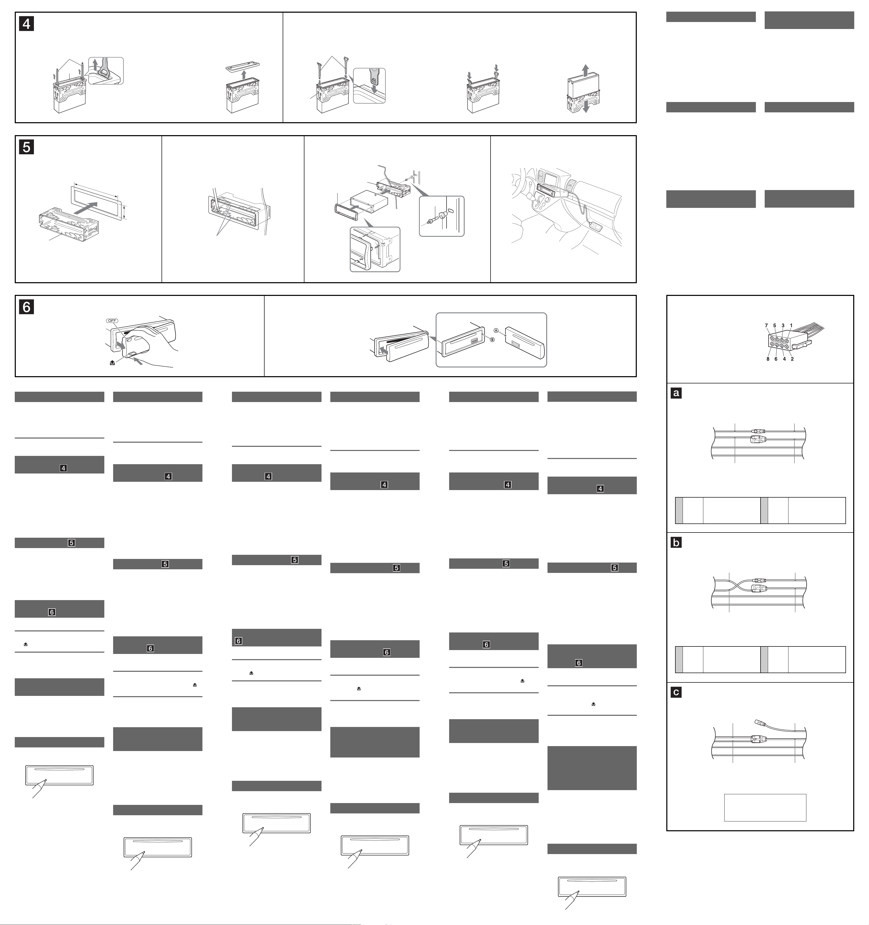
Power connection diagram
Auxiliary power connector may vary depending on the
car. Check your car’s auxiliary power connector diagram
to make sure the connections match correctly. There are
three basic types (illustrated below). You may need to
switch the positions of the red and yellow leads in the car
stereo’s power connecting lead.
After matching the connections and switched power
supply leads correctly, connect the unit to the car’s
power supply. If you have any questions and problems
connecting your unit that are not covered in this manual,
please consult the car dealer.
Stromanschlussdiagramm
Der Hilfsstromanschluss kann je nach Fahrzeugtyp
unterschiedlich sein. Sehen Sie im Hilfsstromanschlussdiagramm für Ihr Fahrzeug nach, wie die
Verbindung ordnungsgemäß vorgenommen werden muss.
Es gibt, wie unten abgebildet, drei grundlegende Typen.
Sie müssen möglicherweise die rote und gelbe Leitung
des Stromversorgungskabels der Autostereoanlage
vertauschen.
Stellen Sie die Anschlüsse her, schließen Sie die
geschalteten Stromversorgungsleitungen richtig an und
verbinden Sie dann das Gerät mit der Stromversorgung
Ihres Fahrzeugs. Wenn beim Anschließen des
Geräts Fragen oder Probleme auftreten, die in dieser
Bedienungsanleitung nicht erläutert werden, wenden Sie
sich bitte an den Autohändler.
Schéma de raccordement
d’alimentation
Le connecteur d’alimentation auxiliaire peut varier
suivant le type de voiture. Vérifi ez le schéma du
connecteur d’alimentation auxiliaire de votre voiture
pour vous assurer que les connexions correspondent. Il
en existe trois types de base (illustrés ci-dessous). Il se
peut que vous deviez commuter la position des câbles
rouge et jaune du câble d’alimentation de l’autoradio.
Après avoir établi les connexions et commuté
correctement les câbles d’alimentation, raccordez
l’appareil à l’alimentation de la voiture. Si vous avez
des questions ou des diffi cultés à propos de cet appareil
qui ne sont pas abordées dans le présent mode d’emploi,
consultez votre concessionnaire automobile.
Diagramma dei collegamenti di
alimentazione
Il connettore di alimentazione ausiliaria può variare a
seconda della macchina. Controllare il diagramma del
connettore di alimentazione ausiliaria della macchina
per essere sicuri che i collegamenti corrispondano
correttamente. Vi sono tre tipi di base (illustrazione
sotto). Potrà essere necessario cambiare le posizioni dei
fi li rosso e giallo nel cavo di alimentazione dello stereo
della macchina.
Dopo aver fatto corrispondere i collegamenti e
aver commutato i cavi di alimentazione, collegare
l’apparecchio all’alimentazione della macchina. Se si
hanno domande o se sorgono problemi che non sono
stati trattati nel manuale nel collegare l’apparecchio,
contattare l’autoconcessionario.
Voedingsaansluitschema
De hulpvoedingsaansluiting kan verschillen afhankelijk
van de auto. Controleer het hulpvoedingsaansluitschema
dat bij dit apparaat wordt geleverd om te zien of de
aansluitingen kloppen. Er zijn drie basistypes (zie
afbeelding hieronder). Het is mogelijk dat u de posities
van de rode en gele kabels in de voedingskabel van het
car audiosysteem moet omwisselen.
Als de aansluitingen en geschakelde voedingskabels
kloppen, sluit u het apparaat aan op de voeding van de
auto. Indien u nog vragen of problemen hebt in verband
met het aansluiten van het apparaat die niet in deze
handleiding vermeld staan, raadpleeg dan de autodealer.
Схема подключения
питания
В разных автомобилях могут использоваться
разные разъемы вспомогательного питания.
Чтобы убедиться в правильности подсоединения,
обpaтитecь к cxeмe paзъeмa для подключeния
вспомогательного питания Вашего автомобиля.
Есть три основных типа (как показано на рисунке
ниже). Возможно, Вам придется поменять
местами подключение красного и желтого
проводов в соединительном кабеле питания
стереосистемы.
После проверки пpaвильноcти подключeния в
paзъeмax подключите аппарат к электропитанию
автомобиля. Если у Вас есть какие-либо вопросы
или проблемы, связанные с подключением
аппарата, которые не рассматриваются в
настоящем руководстве, обратитесь за советом к
дилеру автомобильной фирмы.
A
Precautions
• Choose the installation location carefully so that the
unit will not interfere with normal driving operations.
• Avoid installing the unit in areas subject to dust, dirt,
excessive vibration, or high temperature, such as in
direct sunlight or near heater ducts.
• Use only the supplied mounting hardware for a safe
and secure installation.
Mounting angle adjustment
Adjust the mounting angle to less than 45°.
Removing the protection collar
and the bracket
Before installing the unit, remove the protection
collar and the bracket from the unit.
1 Remove the protection collar .
Engage the release keys together with the
protection collar .
Pull out the release keys to remove the
protection collar .
2 Remove the bracket .
Insert both release keys together between
the unit and the bracket until they click.
Pull down the bracket , then pull up the unit
to separate.
Mounting example
-A Installation in the dashboard
Notes
• Bend these claws outward for a tight fi t, if necessary (-A-2).
• Make sure that the 4 catches on the protection collar are
properly engaged in the slots of the unit (-A-3).
-B Installation of iPod
• Make sure that the iPod is placed where driving is not
obstructed, such as the glove box of the car, etc.
• The length of dock connector cable is 1.25m. Install the
iPod within the reach of the dock connector cable.
How to detach and attach the
front panel
Before installing the unit, detach the front panel.
-A To detach
Before detaching the front panel, be sure to press .
, and pull it off towards you.
Press
-B To attach
Engage part of the front panel with part of the unit,
as illustrated, and push the left side into position until it
clicks.
Warning if your car’s ignition
has no ACC position
Be sure to set the Auto Off function. For details, see the
supplied Operating Instructions.
The unit will shut off completely and automatically in
the set time after the unit is turned off, which prevents
battery drain.
If you do not set the Auto Off function, press and hold
until the display disappears each time you turn
the ignition off.
RESET button
When the installation and connections are completed,
be sure to press the RESET button with a ball-point pen,
etc., after detaching the front panel.
Sicherheitshinweise
• Wählen Sie den Einbauort sorgfältig so aus, dass das
Gerät beim Fahren nicht hinderlich ist.
• Bauen Sie das Gerät so ein, dass es keinen hohen
Temperaturen (keinem direkten Sonnenlicht, keiner
Warmluft von der Heizung), keinem Staub, keinem
Schmutz und keinen starken Vibrationen ausgesetzt ist.
• Für eine sichere Befestigung verwenden Sie stets die
mitgelieferten Montageteile.
Hinweis zum Montagewinkel
Das Gerät sollte in einem Winkel von weniger als 45°
montiert werden.
Abnehmen der Schutzumrandung
und der Halterung
Nehmen Sie vor dem Installieren des Geräts die
Schutzumrandung und die Halterung vom
Gerät ab.
1 Entfernen Sie die Schutzumrandung .
Setzen Sie beide Löseschlüssel an der
Schutzumrandung an.
Ziehen Sie die Schutzumrandung mithilfe
der Löseschlüssel heraus.
2 Entfernen Sie die Halterung .
Führen Sie beide Löseschlüssel zwischen
dem Gerät und der Halterung ein, bis sie
mit einem Klicken einrasten.
Ziehen Sie die Halterung nach unten
und das Gerät nach oben, um die beiden zu
trennen.
Montagebeispiel
-A Installation im Armaturenbrett
Hinweise
• Falls erforderlich, biegen Sie diese Klammern für einen
sicheren Halt nach außen (-A-2).
• Achten Sie darauf, die 4 Verriegelungen an der
Schutzumrandung korrekt in die Aussparungen am Gerät
einzusetzen (-A-3).
-B Installation des iPod
• Montieren Sie den iPod unbedingt an einer Stelle, an
der er beim Fahren nicht hinderlich ist, also z. B. im
Handschuhfach usw.
• Die Länge des Dock-Anschlusskabels beträgt 1,25 m.
Installieren Sie den iPod so, dass er an das DockAnschlusskabel angeschlossen werden kann.
Abnehmen und Anbringen der
Frontplatte
Nehmen Sie die Frontplatte vor dem Einbau des
Geräts ab.
-A Abnehmen
Schalten Sie das Gerät vor dem Abnehmen der
Frontplatte unbedingt mit aus. Drücken Sie
und ziehen Sie sie auf sich zu heraus.
-B Anbringen
Setzen Sie Teil der Frontplatte wie in der Abbildung
dargestellt an Teil des Geräts an und drücken Sie die
linke Seite der Frontplatte an, bis sie mit einem Klicken
einrastet.
Warnhinweis, wenn die Zündung
Ihres Fahrzeugs nicht über eine
Zubehörposition (ACC oder I) verfügt
Aktivieren Sie unbedingt die Abschaltautomatik.
Näheres dazu fi nden Sie in der mitgelieferten
Bedienungsanleitung.
Nach dem Ausschalten wird das Gerät dann nach
der voreingestellten Zeit automatisch vollständig
abgeschaltet, so dass der Autobatterie kein Strom mehr
entzogen wird.
Wenn Sie die Abschaltautomatik nicht aktivieren, müssen
Sie jedes Mal, wenn Sie die Zündung ausschalten,
die Taste gedrückt halten, bis die Anzeige
ausgeblendet wird.
Taste RESET
Wenn Sie das Gerät eingebaut und alle Anschlüsse
vorgenommen haben, müssen Sie die Frontplatte
abnehmen und mit einem Kugelschreiber oder einem
anderen spitzen Gegenstand die Taste RESET drücken.
B
Précautions
• Choisissez soigneusement l’emplacement de
l’installation afi n que l’appareil ne gêne pas la conduite
normale du véhicule.
• Evitez d’installer l’appareil dans un endroit exposé à
de la poussière, de la saleté, des vibrations violentes ou
à des températures élevées, comme en plein soleil ou à
proximité d’un conduit de chauffage.
• Pour garantir un montage sûr, n’utilisez que le matériel
fourni.
Réglage de l’angle de montage
Réglez l’inclinaison à un angle inférieur à 45°.
Retrait du tour de protection et
du support
Avant d’installer l’appareil, retirez le tour de
protection et le support de l’appareil.
1 Retirez le tour de protection .
Enclenchez les clés de déblocage
simultanément dans le tour de protection .
Tirez sur la clé de déblocage pour retirer le
tour de protection .
2 Retirez le support .
Insérez les deux clés de déblocage
simultanément entre l’appareil et le support
jusqu’au déclic indiquant qu’elles sont en
place.
Tirez le support vers le bas, puis tirez
l’appareil vers le haut pour les séparer.
Exemple de montage
-A Installation dans le tableau de bord
Remarques
• Pliez ces griffes vers l’extérieur pour assurer une prise correcte
si nécessaire (-A-2).
• Assurez-vous que les 4 loquets du tour de protection sont
correctement insérés dans les fentes de l’appareil (-A-3).
-B Installation de l’iPod
• Assurez-vous que l’iPod est placé à un endroit qui
ne gêne pas la conduite tel que la boîte à gants de la
voiture, etc.
• La longueur du câble du connecteur dock est de
1,25 m. Installez l’iPod à une distance maximale égale
à la longueur du câble du connecteur dock.
Retrait et fi xation de la façade
Avant d’installer l’appareil, retirez la façade.
-A Pour la retirer
Avant de retirer la façade, appuyez sur . Appuyez
ensuite sur
-B Pour la fi xer
Fixez la partie de la façade sur la partie de
l’appareil, comme indiqué sur l’illustration, puis appuyez
sur le côté gauche jusqu’au déclic.
Avertissement si le contact de
votre voiture ne comporte pas de
position ACC
Veillez à régler la fonction de mise hors tension
automatique. Pour obtenir davantage d’informations,
reportez-vous au mode d’emploi fourni.
L’appareil s’éteint complètement et automatiquement
après le laps de temps choisi une fois l’appareil mis hors
tension afi n d’éviter que la batterie ne se décharge.
Si vous ne réglez pas la fonction de mise hors tension
automatique, appuyez sur la touche et maintenezla enfoncée jusqu’à ce que l’affi chage disparaisse à
chaque fois que vous coupez le contact.
Touche RESET
Une fois que l’installation et les raccordements sont
terminés, retirez la façade et appuyez sur la touche
RESET à l’aide d’un stylo à bille ou d’un autre objet
pointu.
, puis faites glisser la façade vers vous.
Precauzioni
• Scegliere con attenzione la posizione per l’installazione
in modo che l’apparecchio non interferisca con le
operazioni di guida del conducente.
• Evitare di installare l’apparecchio dove sia soggetto ad
alte temperature, come alla luce solare diretta o al getto
di aria calda dell’impianto di riscaldamento, o dove
possa essere soggetto a polvere, sporcizia e vibrazioni
eccessive.
• Usare solo il materiale di montaggio in dotazione per
un’installazione stabile e sicura.
Regolazione dell’angolo di montaggio
Regolare l’angolo di montaggio in modo che sia inferiore
a 45°.
Rimozione della staffa e della
cornice protettiva
Prima di installare l’apparecchio, rimuovere
la cornice protettiva e la staffa
dall’apparecchio.
1 Rimuovere la cornice protettiva .
Inserire le chiavette di rilascio nella cornice
protettiva .
Per rimuovere la cornice protettiva estrarre
le chiavette di rilascio .
2 Rimuovere la staffa .
Inserire contemporaneamente entrambe le
chiavette di rilascio tra l’apparecchio e la
staffa
Estrarre la staffa , quindi sollevare
fi no a che non scattano in posizione.
l’apparecchio per rimuoverlo.
Esempio di montaggio
-A Installazione nel cruscotto
Note
• Piegare verso l’esterno questi morsetti per un’installazione più
sicura, se necessario (-A-2).
• Assicurarsi che i 4 fermi sulla cornice protettiva siano
correttamente inseriti negli alloggiamenti dell’apparecchio
(-A-3).
-B Installazione dell’iPod
• Assicurarsi che l’iPod sia collocato in un punto in cui
non intralci la guida, ad esempio nel vano portaoggetti
dell’auto e così via.
• La lunghezza del cavo del connettore dock è 1,25 m.
Installare l’iPod in un punto raggiungibile dal cavo del
connettore dock.
Rimozione e applicazione del
pannello anteriore
Prima di installare l’apparecchio rimuovere il
pannello anteriore.
-A Per rimuoverlo
Prima di rimuovere il pannello anteriore, premere
. Premere
anteriore.
, quindi tirare verso di sé il pannello
-B Per reinserirlo
Applicare la parte del pannello anteriore alla parte
dell’apparecchio come mostrato nell’illustrazione e
premere il lato sinistro fi no a sentire uno scatto.
Avvertenza relativa all’installazione
su un’auto sprovvista della
posizione ACC (accessoria) sul
blocchetto di accensione
Accertarsi di impostare la funzione di spegnimento
automatico. Per ulteriori informazioni, fare riferimento
alle istruzioni per l’uso in dotazione.
L’apparecchio si spegne completamente e
automaticamente all’ora impostata dopo che è stato
disattivato, onde evitare che la batteria si scarichi.
Se la funzione di spegnimento automatico non è stata
impostata, ogni volta che il motore viene spento tenere
premuto fi nché il display non viene disattivato.
Tasto RESET
Una volta completate le procedure di installazione e i
collegamenti, accertarsi di premere il tasto RESET con
una penna a sfera o un oggetto simile dopo avere rimosso
il pannello anteriore.
Voorzorgsmaatregelen
• Kies de installatieplaats zorgvuldig zodat het apparaat
de bestuurder niet hindert tijdens het rijden.
• Installeer het apparaat niet op plaatsen waar het
blootgesteld wordt aan hoge temperaturen, b.v. in
direct zonlicht of bij de warme luchtstroom van de
autoverwarming, aan sterke trillingen, of waar het in
contact komt met veel stof of vuil.
• Gebruik voor het veilig en stevig monteren van
het apparaat uitsluitend de bijgeleverde montageonderdelen.
Maximale montagehoek
Installeer het apparaat nooit onder een hoek van meer
dan 45° met het horizontale vlak.
De beschermende rand en de
beugel verwijderen
Voordat u het apparaat gaat installeren, moet
u de beschermende rand en de beugel
verwijderen van het apparaat.
1 Verwijder de beschermende rand .
Bevestig de ontgrendelingssleutels op de
beschermende rand .
Trek de ontgrendelingssleutels naar u toe
om de beschermende rand te verwijderen.
2 Verwijder de beugel .
Plaats de ontgrendelingssleutels tussen het
apparaat en de beugel
Trek de beugel omlaag en trek het apparaat
omhoog om deze van elkaar te scheiden.
tot deze vastklikken.
Montagevoorbeeld
-A Montage in het dashboard
Opmerkingen
• Indien nodig kunt u deze klemhaken ombuigen voor een
steviger bevestiging (-A-2).
• De 4 grepen op de beschermende rand moeten goed in de
sleuven van het apparaat zijn geplaatst (-A-3).
-B iPod installeren
• Leg de iPod neer op een plaats waar deze de
besturing van de auto niet belemmerd, zoals in het
handschoenenkastje van de auto, enzovoort.
• De lengte van de dockconnectorkabel is 1,25 m.
Installeer de iPod binnen het bereik van de
dockconnectorkabel.
Het voorpaneel verwijderen en
bevestigen
Verwijder, alvorens met het installeren te
beginnen, het voorpaneel.
-A Verwijderen
Vergeet niet, voordat u het voorpaneel verwijdert, eerst
op te drukken. Druk vervolgens op de
trek het naar u toe.
toets en
-B Bevestigen
Breng deel van het voorpaneel aan op deel van het
apparaat zoals afgebeeld en druk op de linkerzijde tot
deze vastklikt.
Waarschuwing als het
contactslot van de auto geen
ACC-positie heeft
Zorg ervoor dat u de functie voor automatisch
uitschakelen instelt. Raadpleeg de bijgeleverde
gebruiksaanwijzing voor meer informatie.
Het apparaat wordt na de ingestelde tijd automatisch
volledig uitgeschakeld nadat het apparaat is
uitgeschakeld. Zo wordt voorkomen dat de accu
leegloopt.
Als u de functie voor automatisch uitschakelen niet
instelt, moet u ingedrukt houden tot het display
verdwijnt telkens wanneer u het contact uitschakelt.
RESET-toets
Als u de installatie en aansluitingen hebt voltooid,
moet u met een puntig voorwerp, zoals de punt van een
balpen, op RESET drukken nadat u het voorpaneel hebt
verwijderd.
Меры предосторожности
• Место для установки аппарата выбирайте
тщательно, чтобы он не мешал нормальному
управлению автомобилем.
• Не устанавливайте аппарат там, где он
будет подвержен воздействию пыли, грязи,
чрезмерной вибрации или высоких температур,
например в местах, попадающих под прямые
солнечные лучи или находящихся вблизи
вентиляционных решеток обогревателей.
• В целях обеспечения надежной и безопасной
установки используйте лишь входящие в
комплект монтажные детали.
Допустимый угол установки
Установите аппарат под углом не более 45°.
Cнятиe зaщитной мaнжeты
и кpонштeйнa
Пepeд ycтaновкой аппарата снимите с него
зaщитнyю мaнжeтy и кpонштeйн .
1 Cнятиe зaщитной мaнжeты .
Для cнятия зaщитной мaнжeты
иcпользyйтe ключи для дeмонтaжa .
Потянитe нa ceбя ключи для дeмонтaжa
, чтобы cнять зaщитнyю мaнжeтy .
2 Cнятиe кpонштeйнa .
Bcтaвьтe одновpeмeнно до щeлчкa
обa ключa для дeмонтaжa мeждy
аппаратом и кpонштeйном
Потянитe кpонштeйн
- ввepx, чтобы отдeлить одно от дpyгого.
.
вниз, a аппарат
Пpимep ycтaновки
-A
Установка аппарата в приборной пaнeли
Пpимeчaния
• Пpи нeобxодимоcти отогнитe эти выcтyпы нapyжy, чтобы
обecпeчить плотнyю подгонкy (-A-2).
• Убeдитecь, что 4 фикcaтоpa, имeющиecя нa зaщитной
мaнжeтe , нaдeжно вcтaвлeны в отвepcтия нa аппарате
(-A-3).
-B Установка iPod
• Убедитесь, что устройство iPod установлено в
месте, где оно не мешает вождению, например в
перчаточном ящике автомобиле и т.д.
• Длина кабеля с разъемом для док-станции
составляет 1,25 м. Установите устройство iPod
так, чтобы дотягивался кабель с разъемом для
док-станции.
Порядок снятия и
установки передней
панели
Перед установкой аппарата снимите с него
переднюю панель.
-A Снятие панели
Прежде чем снимать переднюю панель,
обязательно отключите аппарат, нажав клавишу
. Haжмитe кнопкy
потянyв ee нa ceбя.
, зaтeм cнимитe пaнeль,
-B Установка панели
Сначала присоедините часть передней
панели к части аппарата, как это показано на
иллюстрации, а затем вдвиньте в паз левую часть
панели до легкого щелчка.
Предостережение относительно
аппаратуры, установленной в
автомобиле, в зaмкe зажигания
котоpого нeт отдельного
положения ACC для отключения
подсоединенной аппаратуры
Задайте функцию автоматического выключения.
Для получения дополнительной информации см.
прилагаемые инструкции по эксплуатации.
После выключения аппарата его питание будет
автоматически отключено в установленное
время, что предотвращает разрядку
аккумулятора.
Если функция автоматического выключения не
задана, то при каждом выключении зажигания
нажмите и удерживайте кнопку до тех пор,
пока дисплей не погаснет.
Auxiliary power connector
Hilfsstromanschluss
Connecteur d’alimentation auxiliaire
Connettore di alimentazione ausiliaria
Hulpvoedingsaansluiting
Вспомогательный разъем питания
4
4
Yellow
Gelb
Jaune
Giallo
Geel
Желтый
Yellow
Gelb
Jaune
Giallo
Geel
Желтый
continuous power supply
permanente Stromversorgung
alimentation continue
alimentazione continua
continu voeding
непрерывное поступление питания
switched power supply
geschaltete Stromversorgung
alimentation commutée
alimentazione commutata
geschakelde voeding
коммутируемый питание
Red
Rot
Rouge
Rosso
Rood
Красный
Yellow
Gelb
Jaune
Giallo
Geel
Желтый
Red
Rot
Rouge
7
Rosso
Rood
Красный
Red
Rot
Rouge
Rosso
Rood
Красный
Yellow
Gelb
Jaune
Giallo
Geel
Желтый
Red
Rot
Rouge
7
Rosso
Rood
Красный
Red
Rot
Rouge
Rosso
Rood
Красный
Yellow
Gelb
Jaune
Giallo
Geel
Желтый
the car without ACC position
Fahrzeug ohne Zubehörposition (ACC oder I)
Véhicule sans position ACC
Auto priva della posizione ACC
Auto zonder ACC-positie
автомобиль не имеет положения АСС
Red
Rot
Rouge
Rosso
Rood
Красный
Yellow
Gelb
Jaune
Giallo
Geel
Желтый
geschaltete Stromversorgung
alimentation commutée
alimentazione commutata
коммутируемый питание
Red
Rot
Rouge
Rosso
Rood
Красный
Yellow
Gelb
Jaune
Giallo
Geel
Желтый
continuous power supply
permanente Stromversorgung
alimentazione continua
непрерывное поступление питания
Red
Rot
Rouge
Rosso
Rood
Красный
Yellow
Gelb
Jaune
Giallo
Geel
Желтый
switched power supply
geschakelde voeding
alimentation continue
continu voeding
Кнопкa RESET
Когдa ycтaновкa и подcоeдинeния бyдyт
зaкончeны, обязaтeльно нaжмитe кнопкy
RESET c помощью шapиковой pyчки и т.п.,
пpeдвapитeльно cняв пepeднюю пaнeль.
 Loading...