

Page 1
Mounting the Unit in a Japanese
Car
3-810-777-21 (1)
Installation de l’appareil dans
une voiture japonaise
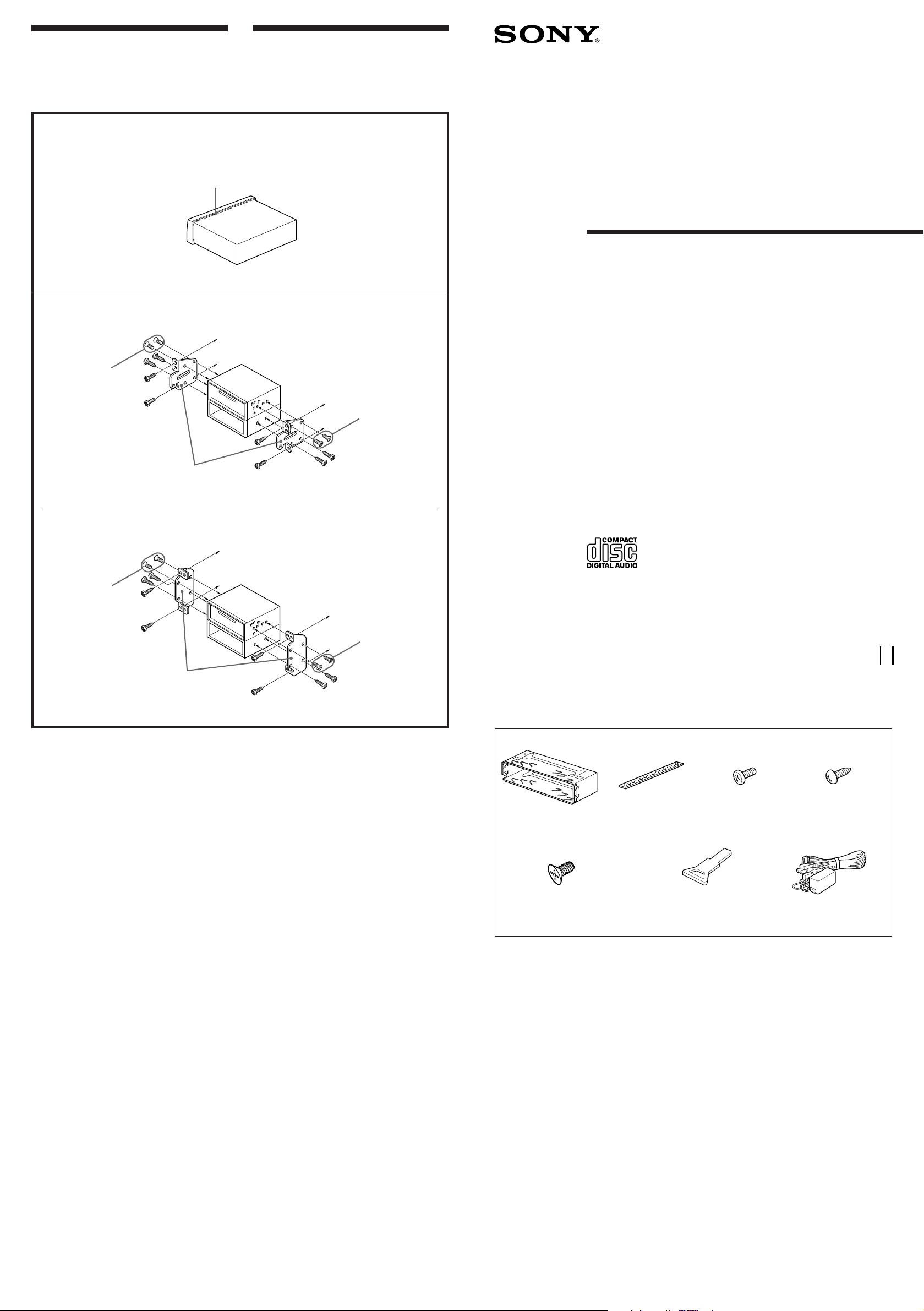
You may not be able to install this unit in some
makes of Japanese cars. In such a case, consult
your Sony dealer.
Run a blade along the slits on the back of the front trim and cut it off the unit.
Passer une lame le long des fentes à l’arrière de la bordure et la couper.
1
Slit
Fente
TOYOTA
2
5 max. size M5 × 8 mm
Dimension max.
M5 × 8 mm
Si vous ne pouvez pas installer l’appareil dans
une voiture japonaise, consultez votre revendeur
Sony.
FM/AM
Compact Disc
Player
Installation/Connections
Installation/Connexions
to dashboard/center console
au tableau de bord/console centrale
5 max. size M5 × 8 mm
Dimension max.
M5 × 8 mm
Bracket
Support
NISSAN
5 max. size M5 × 8 mm
Dimension max.
M5 × 8 mm
Bracket
Support
Note
To prevent malfunction, install only with the supplied screws
5 and use existing parts supplied to your car.
to dashboard/center console
au tableau de bord/console centrale
5 max. size M5 × 8 mm
Dimension max.
M5 × 8 mm
Remarque
Pour éviter tout dysfonctionnement, utilisez uniquememt les
vis de montage fournies 5 ainsi que les composants existants
de votre voiture.
CDX-5100
Sony Corporation 1995 Printed in Thailand
Parts for Installation and
Connections
The numbers in the list are keyed to those in
the instructions.
1
TOP
2
Matériel de montage fourni
Les numéros de la liste correspondent à ceux des
instructions.
3
4
× 1
5
× 6
(incl. 2 reserve)
(2 réserves comprises)
The release key 6 is used for dismounting
the unit. See the operating instructions
manual for details.
6
× 1 × 1
7
× 1
La clé de dégagement 6 est nécessaire pour
démonter l’appareil. Consulter le mode d’emploi
pour plus de détails.
× 1
× 1
Page 2
Installation Installation
TOP
Precautions
• Do not tamper with the four holes on the upper
surface of the unit. They are for tuner
adjustments to be done only by service
technicians.
• Choose the installation location carefully so that
the unit will not hamper the driver during
driving.
• Avoid installing the unit where it would be
subject to high temperatures, such as from direct
sunlight or hot air from the heater, or where it
would be subject to dust, dirt or excessive
vibration.
• Use only the supplied mounting hardware for a
safe and secure installation.
Mounting angle adjustment
Adjust the mounting angle to less than 20°.
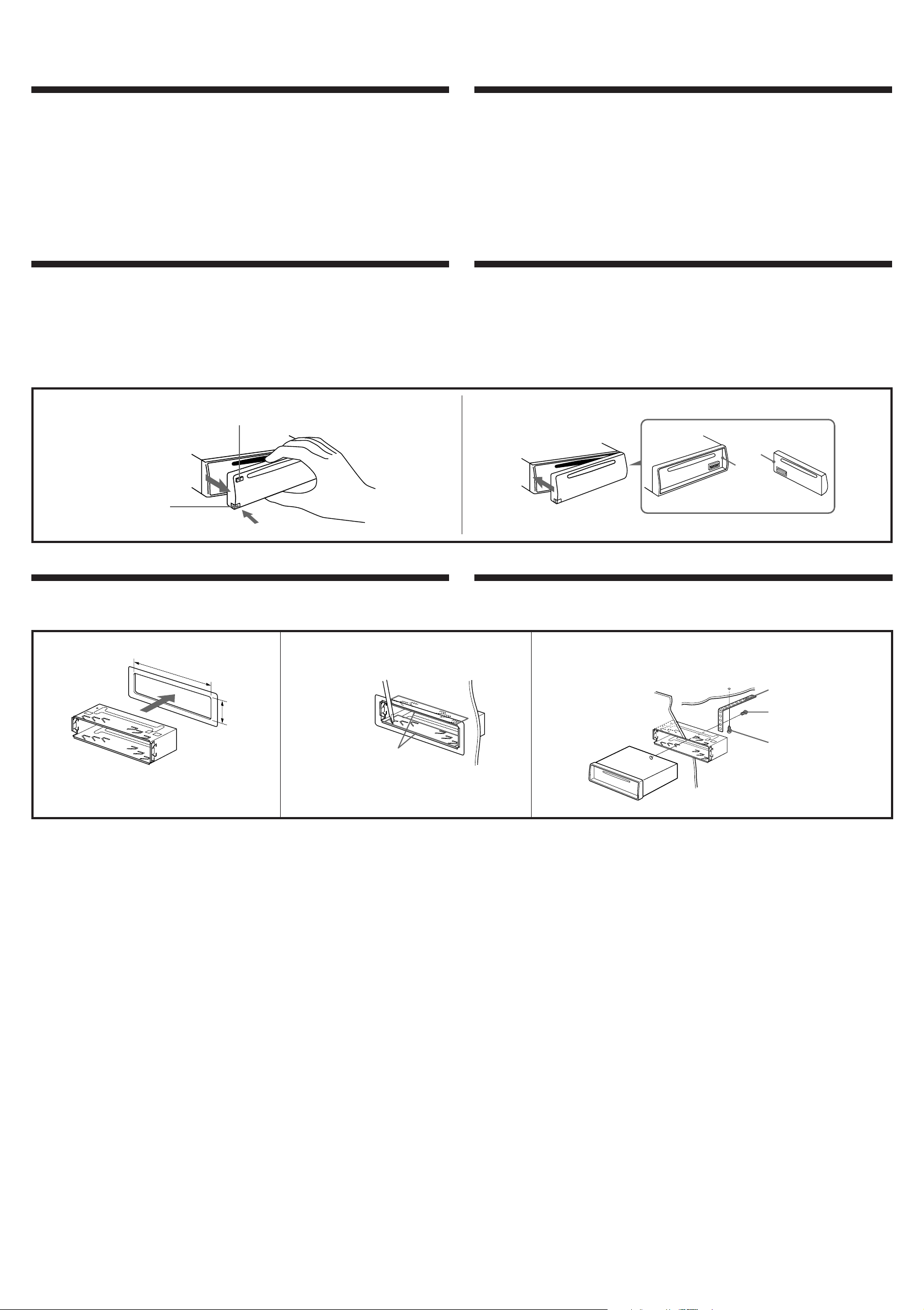
How to Detach and Attach the Front Panel
Before installing the unit, detach the front panel.
To detach
Before detaching the front panel, be sure to press
the OFF button first. Then press the RELEASE
button to open up the front panel by pulling it
towards you as illlustrated.
To detach
Retrait
OFF button
Touche OFF
To attach
Align the parts A and B, and push the front
panel until it clicks.
Précautions
• Ne pas toucher les quatre orifices sur le panneau
supérieur de l’appareil. Ils servent aux réglages
du tuner qui ne doivent être effectués que par
un technicien.
• Choisir soigneusement l’emplacement de
l’installation, pour que l’appareil ne gêne pas la
conduite.
Retrait et pose du panneau avant
Avant d’installer l’appareil, déposer la panneau avant.
Retrait
Avant de détacher la façade, appuyez sur la
touche OFF. Appuyez ensuite sur la touche
RELEASE pour ouvrir la façade. Enlevez-la en la
tirant vers vous, comme indiqué sur l’illustration.
To attach
Pose
• Eviter d’installer l’appareil dans un endroit
exposé à des températures élevées, comme en
plein soleil ou à proximité d’une bouche d’air
chaud, ou à de la poussière, saleté ou vibrations
violentes.
• Pour garantir un montage sûr, n’utiliser que le
matériel fourni.
Réglage de l’angle de montage
Ajuster l’inclinaison à un angle inférieur à 20°.
Pose
Aligner les points A et B, puis pousser l’appareil
jusqu’au déclic.
RELEASE button
Touche RELEASE
Mounting Example
Installation in the dashboard
12
TOP
1
With the TOP marking up
Avec l’inscription TOP vers le haut
182 mm
53 mm
Bend these claws, if necessary.
Si nécessaire, plier ces griffes.
Exemple de montage
Installation dans le tableau de bord
To support the unit
Pour installer l’appareil
Dashboard
Tableau de bord
Fire wall
Paroi ignifuge
A
B
2
3 max. size M4 × 6 mm
Dimension max. M4 × 6 mm
4
Page 3

Connections Connexions
Caution Précautions
• This unit is designed for negative ground
12 V DC operation only.
• Before making connections, disconnect the
ground terminal of the car battery to avoid short
circuits.
• Connect the yellow and red power input leads
only after all other leads have been connected.
• Be sure to connect the red power input lead to
the positive 12 V power terminal which is
energized when the ignition key is in the
accessory position.
• Run all ground wires to a common ground
point.
• The use of optical instruments with this product
will increase eye hazard.
• Cet appareil est conçu pour fonctionner sur
courant continu de 12 V avec masse négative.
• Avant d’effectuer les connexions, débrancher la
borne de terre de la batterie du véhicule pour
éviter tout court-circuit.
• Brancher les fils d’entrée d’alimentation jaune et
rouge seulement après avoir terminé tous les
autres branchements.
• Veiller à ne pas raccorder le fil rouge d’entrée
d’alimentation à la borne positive de 12 V qui est
alimentée quand la clé de contact est sur la
position accessoires.
• Rassembler tous les fils de terre en un point
de masse commun.
If Your Car has no Accessory Position on the Ignition Key Switch
— POWER SELECT Switch
The illumination on the front panel is factory-set
to be turned on even when the unit is not being
played. However, this setting may cause some car
battery wear if your car has no accessory
position on the ignition key switch. To avoid
this battery wear, set the POWER SELECT
switch located on the bottom of the unit to the
B position, then press the reset button. The
illumination is reset to stay off while the unit is
not being played.
Note
The caution alarm for the front panel is not activated when the
POWER SELECT switch is set to the B position.
Change the position with a jeweler’s screwdriver, etc.
Changer la position avec un tournevis de joailler ou un objet
similaire.
Reset Button
When the installation and connections are over, be
sure to press the reset button with a ball-point pen
etc.
Si l’appareil est utilisé dans une voiture dont la clé de contact n’a pas
de position accessoires
L’éclairage du panneau avant est réglé en usine
de manière à s’allumer même quand l’appareil ne
fonctionne pas. Cependant, ce réglage risque
d’épuiser la batterie si l’appareil est utilisé dans
une voiture dont la clé de contact ne possède
pas de position accessoires. Pour éviter
d’épuiser la batterie, régler l’interrupteur POWER
SELECT sur le socle de l’appareil sur la position
— Interrupteur POWER SELECT
B, puis appuyer sur la touche de
réinitialisation. L’éclairage est réglé pour rester
éteint quand l’appareil n’est pas utilisé.
Remarque
Quand l’interrupteur POWER SELECT est réglé sur la
position B, l’avertisseur du panneau avant ne fonctionne pas.
Touche de réinitialisation
Quand l’installation et les connexions sont
terminées, appuyer sur la touche de
réinitialisation avec un stylo bille ou un objet
pointu.
Connection Diagram
Example 1
Exemple 1
CDX-5100
Front speakers
Haut-parleurs avant
Rear speakers
Haut-parleurs arrière
Reset button
Touche de réinitialisation
Schémas de connexion
Example 2
Exemple 2
LINE OUT
REAR
CDX-5100
Power amplifier
Amplificateur de puissance
Front speakers
Haut-parleurs avant
Rear speakers
Haut-parleurs arrière
Rear speakers
Haut-parleurs arrière
Example 3
Exemple 3
CDX-5100
Power amplifier
Amplificateur de puissance
LINE OUT
REAR
LINE OUT
FRONT
Power amplifier
Amplificateur de puissance
Front speakers
Haut-parleurs avant
Rear speakers
Haut-parleurs arrière
Page 4

Connections of Example
Connexions de l’exemple
Rotary commander (RM-X2S) (Not supplied)
Satellite de commande (RM-X2S) (non fourni)
Left
Gauche
REMOTE IN
7
White
Blanc
LINE OUT REAR
LINE OUT
FRONT
Blue/white striped
Rayé bleu/blanc
Max. supply current 0.3 A
Courant max. fourni 0,3 A
from car antenna
de l’antenne de la voiture
RCA pin cord (RC-63 (1 m), RC-64 (2 m)
or RC-65 (5 m)) (not supplied)
Cordon à broche RCA (RC-63 (1 m),
RC-64 (2 m) ou RC-65 (5 m)) (non fourni)
AMP REM
to antenna remote
(to a power antenna relay control box)
à l’antenne lointain
(vers le boitier à relais de l’antenne électrique)
Rear speakers
Haut-parleurs arrière
Power amplifier
Amplificateur de puissance
Power amplifier
Amplificateur de puissance
Front speakers
Haut-parleurs avant
Front speakers
Haut-parleurs avant
Gray
Right
Droit
Left
Gauche
Rear speakers
Haut-parleurs arrière
Right
Droit
Notes on the control leads
• The AMP REM lead (blue/white striped) supplies +12 V DC when you turn on the unit. When the AMP REM lead is
connected to the power antenna, the antenna will be extended as long as the unit is turned on.
• A power antenna without relay box cannot be used with this unit.
Memory hold connection
When the yellow power input lead is connected, power will always be supplied to the memory circuit even when the ignition key is
turned off.
Notes on speaker connection
• Before connecting the speakers, turn the unit off.
• Use speakers with an impedance of 4 to 8 ohms, and with adequate power handling capacities. Otherwise, the speakers may be
damaged.
• Do not connect the terminals of the speaker system to the car chassis, and do not connect the terminals of the right speaker with
those of the left speaker.
• Do not attempt to connect the speakers in parallel.
• Do not connect any active speakers (with built-in amplifiers) to the speaker terminals of the unit. Doing so may damage the
active speakers. Therefore, be sure to connect passive speakers to these terminals.
Gris
Green
Vert
Purple
Mauve
Red
Rouge
Yellow
Jaune
Black
Noir
to the +12 V power terminal which is energized in the accessory
position of the ignition key
Be sure to connect the black ground lead to it first
Fuse
Fusible
Fuse
Fusible
Remarques sur les fils de contrôle
• Le fil d’AMP REM (rayé bleu/blanc) fournit du courant continu de +12 V lorsque vous mettez l’appareil sous tension. Si le fil
d’AMP REM est raccordé à l’antenne électrique, l’antenne restera déployée aussi longtemps que l’appareil sera sous tension.
• Une antenne électrique sans boîtier de relais ne peut pas être utilisée avec cet appareil.
Connexion pour la conservation de la mémoire
Lorsque le fil d’entrée d’alimentation jaune est connecté, le circuit de la mémoire est alimenté en permanence même si la clé de
contact est sur la position d’arrêt.
Remarques sur la connexion des haut-parleurs
• Avant de raccorder les haut-parleurs, mettre l’appareil hors
tension.
• Utiliser des haut-parleurs ayant une impédance de 4 à 8 ohms et une capacité adéquate sous peine de les endommager.
• Ne pas raccorder les bornes du système de haut-parleurs au châssis de la voiture et ne pas connecter les bornes du haut-parleur
droit à celles du haut-parleur gauche.
• Ne pas tenter de raccorder les haut-parleurs en parallèle.
• Ne pas raccorder des haut-parleurs actifs (avec amplificateurs intégrés) aux bornes de haut-parleur de l’appareil sous peine de
les endommager. Veiller à raccorder des haut-parleurs passifs à ces bornes.
à la borne d’alimentation de +12 V qui est alimentée quand la
clé de contact est sur la position accessoire
Raccordez d’abord le fil de masse noir.
to the +12 V power terminal which is energized at all times
Be sure to connect the black ground lead to it first.
à la borne d’alimentation +12 V qui est alimentée en
permanence
Raccordez d’abord le fil de masse noir.
to a metal point of the car
First connect the black ground lead, then connect the yellow
and red power input leads.
vers un point métallique de la voiture
Branchez d’abord le fil de masse noir et, ensuite, les fils d’entrée
d’alimentation jaune et rouge.
 Loading...