

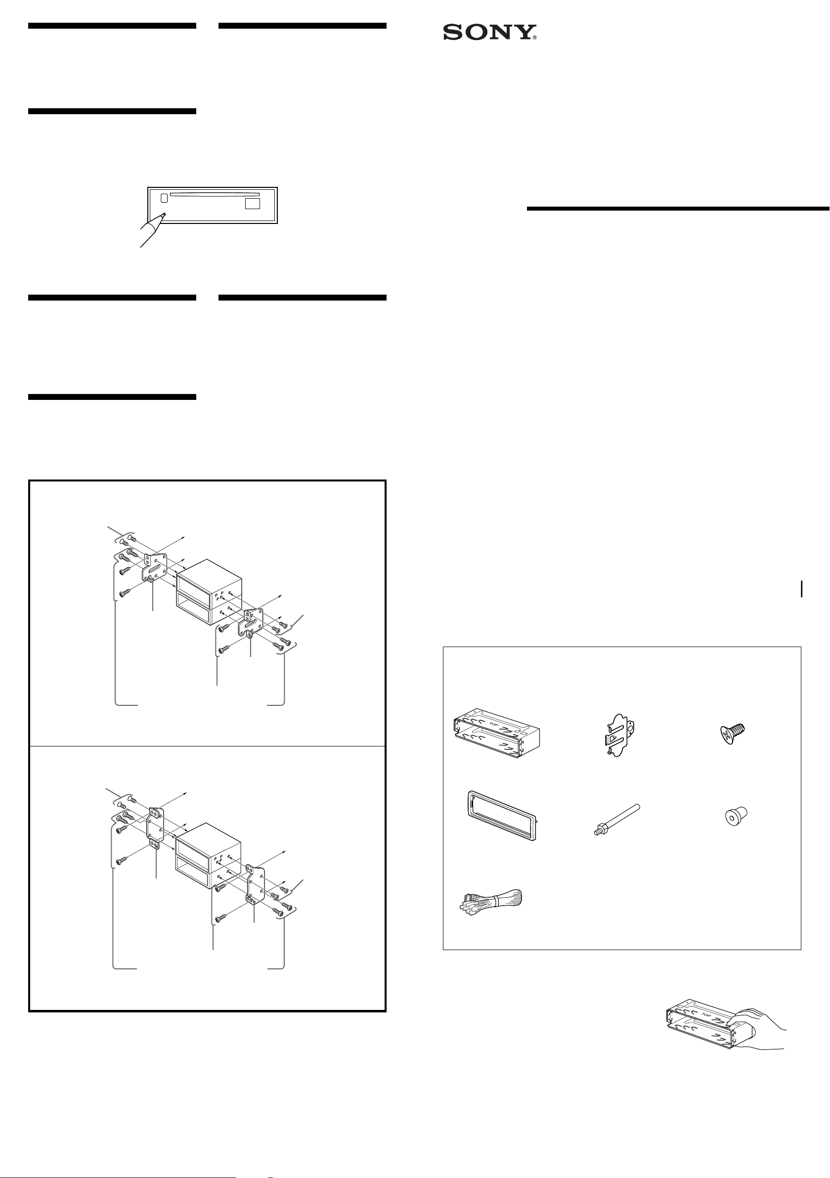
Reset button
When the installation and connections are
completed, be sure to press the reset button
with a ball-point pen, etc.
3-044-884-11 (1)
›«‰«¶s
• ƒw‚¸'M‡s– §„ƒ¤«Æ¡A ¨‰—¥˛¶Œfl] § ¥« £›«‰ «
¶s¡C
Botón de restauración
Cuando finalice la instalación y las conexiones,
cerciórese de pulsar el botón de restauración
con un bolígrafo, etc.
Mounting the unit in a
Japanese car
You may not be able to install this unit in some
makes of Japanese cars. In such a case, consult
your Sony dealer.
Montaje de la unidad en un
automóvil japonés
FM/AM
Compact Disc
Player
Installation/Connections
Instalación/Conexiones
ƒw‚¸¡ ‰u‚ ⁄§‡s–
–N¥» ƒw‚¸' ⁄Ø¥»†£¤T¤fi⁄Wfi
ƒ‡“”⁄Ø¥»†£¤T¤fi⁄£fl ƒw‚¸¥» ¡Aƒb‡o” –¡§˛⁄U¡A‰—
–zƒV• ƒa“” Sony ‚gP ¿‚¡C
Usted no podrá instalar esta unidad en algunos
automóviles japoneses. En tal caso, consulte a
su proveedor Sony.
TOYOTA
3
max. size
5 × 8 mm
Tamaño máx.
5 × 8mm
‡ ⁄j⁄ ⁄o
5¡ 8 mm
Bracket
Soporte
ƒ«‹[
Existing parts supplied to your car
Piezas existentes suministradas con su
automóvil
H¤T¤fi“ e“”‡¡¥
to dashboard/center console
al salpicadero/consola central
ƒ » “ “O¡ ⁄⁄¥¡––¤ ‰c
3
max. size
5 × 8 mm
Tamaño máx.
5 × 8mm
Bracket
Soporte
ƒ«‹[
‡ ⁄j⁄ ⁄o
5¡ 8 mm
CDX-4800X
Sony Corporation © 2000 Printed in Korea
Parts Iist
Lista de componentes
„s¥ ⁄@˜ “
The numbers in the list are keyed to those in the instructions.
Los números de la lista corresponden a los de las instrucciones.
„ˇ¥ …˘ƒr»P»¡'œfi ⁄⁄“”…˘ƒr‹O⁄@›P“”¡C
1
23
NISSAN
3 max. size
5 × 8 mm
Tamaño máx.
5 × 8mm
‡ ⁄j⁄ ⁄o
5¡ 8 mm
Bracket
Soporte
ƒ«‹[
Existing parts supplied to your car
Piezas existentes suministradas con su
automóvil
H¤T¤fi“ e“”‡¡¥
Note
To prevent malfunction, install only with the
supplied screws 3.
Nota
Para evitar que se produzcan fallos, realice la
instalación solamente con los tornillos
suministrados 3.
to dashboard/center console
al salpicadero/consola central
ƒ » “ “O¡ ⁄⁄¥¡––¤ ‰c
3
max. size
5 × 8 mm
Tamaño máx.
5 × 8mm
‡ ⁄j⁄ ⁄o
5¡ 8 mm
Bracket
Soporte
ƒ«‹[
ø
‹ ¤ ⁄ o¥˝‹G» ¡Aƒw‚¸fi ¥ufl ¤ˇ¥˛“ e“”`‡ • 3¡C
45
7
Caution
Cautionary notice for handling the bracket 1.
Handle the bracket carefully to avoid injuring your fingers.
Precaución
Advertencia sobre la manipulación del soporte 1.
Tenga mucho cuidado al manipular el soporte para evitar
posibles lesiones en los dedos.
“‘•N
† ˚‚¸¤ł⁄ ‹[ 1 fi ¡A‰—flS§O“‘•N§O¶¸¤⁄«¡C
× 4× 2
6
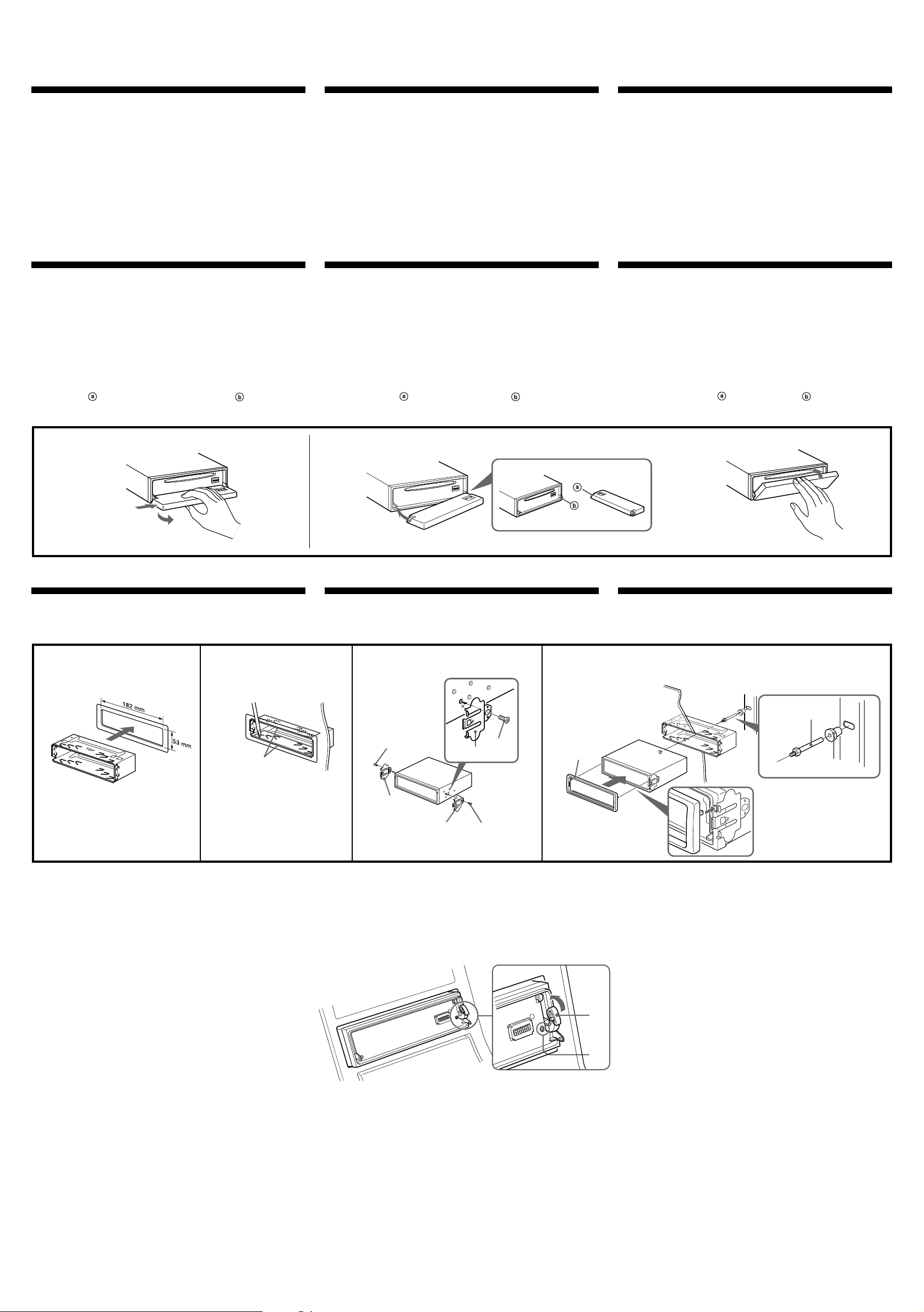
Installation
Instalación ƒw‚¸
Precautions
•Choose the installation location carefully so that the unit will not
interfere with normal driving operations.
•Avoid installing the unit in areas subject to dust, dirt, excessive
vibration, or high temperatures, such as in direct sunlight or near
heater ducts.
•Use only the supplied mounting hardware for a safe and secure
installation.
Mounting angle adjustment
Adjust the mounting angle to less than 60°.
How to detach and attach the front panel
Before installing the unit, detach the front panel.
A To detach
Before detaching the front panel, be sure to press (OFF) first.
Then press (OPEN) to open the front panel, then slide the front panel
to the right side, and pull out the left side of the front panel.
B To attach
Place the hole in the front panel onto the spindle on the unit as
illustrated, then push the left side in.
Precauciones
•Elija cuidadosamente el lugar de montaje de forma que la unidad no
interfiera las funciones normales de conducción.
•Evite instalar la unidad donde pueda quedar sometida a altas
temperaturas, como a la luz solar directa o al aire caliente de
calefacción, o a polvo, suciedad, o vibraciones excesivas.
•Para realizar una instalación segura y firme, utilice solamente la
ferretería de montaje suministrada.
Ajuste del ángulo de montaje
Ajuste el ángulo de montaje a menos de 60°.
Forma de extraer e instalar el panel frontal
Antes de instalar la unidad, extraiga el panel frontal.
A Para extraerlo
Antes de extraer el panel frontal, ceriórese de presionar (OFF).
Después presione (OPEN) a fin de abrirlo, después deslícelo hacia la
derecha, y por último tire de su parte izquierda.
B Para instalarlo
Coloque el orificio del panel frontal en el eje de la unidad, como
se muestra en la ilustración, y después presione la parte izquierda.
¤ˇ¥˛«e“‘•N¤˘¶
¥» ‰—'æƒb⁄£§«ˆ“¥q r p⁄§‡B¡C
•` §K–N¥» 'æƒb “•¯⁄§‡B¡Aƒp¶§¥œ“‰– • fig¡B•xfi «e¡B'˛ƒ˙„—•¥ƒ
¯…¶ˆ¡A¥H⁄˛•¥' ¤ _ ˚ ¥ƒa⁄Ł¡C
•‹ ⁄Fƒw¥ _¤£¡Aƒw‚¸fi ‰—¤ˇ¥˛“ e“”‡¡¥ ¡C
ƒw‚¸¤⁄« ⁄§‰ ª
‰—ƒb60« ¥H⁄”‰ ªƒw‚¸¤⁄« ¡C
ƒpƒ ' ¤ł'M‚¸ t«e“O
ƒw‚¸¥» ⁄§«e¡A‰—¥ ' ¤ł«e“O¡C
A '¤ł
' ¤ł«e›–“O⁄§«e¡A¶•¥ « ⁄U (OFF) `¡C
M«Æ¡A« ⁄U (OPEN) ` ¥H«K¶}– «e›–“O¡A–N«e›–“O y•LƒV¥kˆ •˘ ˚¡A
M«Æ–q«e›–“O“”¥“ …' ¥X¡C
B ‚¸ t
ƒp„ˇ' ¥ ¡A–N«e“O“” ⁄ •fƒb¥» “”⁄ ¶b ⁄W¡A M«Æ– ⁄J¥“ …¡C
A
1
Mounting example
Installation in the dashboard
1
1
With the TOP marking up.
Con la marca TOP hacia arriba.
›n¤ˇ–a TOP …— O›–·´⁄W¡C
2
B
Ejemplo de montaje
Instalación en el salpicadero
2 3
Bend these claws outward
for a tight fit, if necessary.
Si es necesario, doble estas uñas hacia
fuera para que encaje firmemente.
›Yƒ‡¥†›n¡A«h¥i¯sƒ–‡o¤˙¥d⁄ ¡C
3
2
2
2
3
3
ƒw‚¸¥ ¤
ƒw‚¸ƒb» ¿ “O‚
To support the unit
Sujeción de la unidad
4
›n⁄…¥»
Dashboard
Salpicadero
»““O
4
1
c
TOP
Fire wall
Panel cortafuegos
¤⁄ı
5
6
Note
When installing this unit: Depending on car type, the mounting
angle may not allow the front panel to open easily. In such a
case, remove the silver screw A shown below.
When screwing it on again, first lock the lever B. Attaching the screw
without doing so may cause the unit to break.
Nota
Cuando instale esta unidad: Es posible que el ángulo de montaje
(en función del tipo de automóvil) no permita que el panel frontal
se abra con facilidad. En tal caso, extraiga el tornillo plateado A
mostrado más abajo.
Cuando vuelva a atornillarlo, bloquee primero la palanca B. Si fija el
tornillo sin realizar lo expuesto, la unidad podría romperse.
A
ø
ƒw‚¸¥» fi ¡Gƒ‡¤˙¤fi«‹“”¤fi‰ł¤ ƒw‚¸¤⁄« ¥ifl •|¤ˇ „“”«e›–“O⁄£
¶}– ¡Cƒ„fi ¡A‰—ƒp⁄U›–' ¥ ¤ł⁄U»¨`‡ v A¡C
ƒA– ⁄W`‡ vfi ¡A‰—¥ ´Œ'w §@– B¡C‚¸`‡ vfi ⁄£ƒpƒ„§@¡A«K¥ifl ‡y
ƒ¤ „fl} ı¡C
B
 Loading...