

Page 1

3-863-129-11 (1)
Camera Control Unit
Operating Instructions
Before operating the unit, please read this manual thoroughly and retain it for future
reference.
CCU-TX50/50P
© 2004 Sony Corporation
Page 2

WARNING
To prevent fire or shock hazard, do not expose
the unit to rain or moisture.
To avoid electrical shock, do not open the
cabinet. Refer servicing to qualified personnel
only.
THIS APPARATUS MUST BE EARTHED.
This symbol is intended to alert the user to
the presence of important operating and
maintenance (servicing) instructions in the
literature accompanying the appliance.
For the customers in the USA (for
CCU-TX50)
This equipment has been tested and found to comply
with the limits for a Class A digital device, pursuant to
Part 15 of the FCC Rules. These limits are designed to
provide reasonable protection against harmful
interference when the equipment is operated in a
commercial environment. This equipment generates,
uses, and can radiate radio frequency energy and, if not
installed and used in accordance with the instruction
manual, may cause harmful interference to radio
communications. Operation of this equipment in a
residential area is likely to cause harmful interference in
which case the user will be required to correct the
interference at his own expense.
Compliance with these directives implies conformity to
the following European standards:
• EN60950: Product Safety
• EN55103-1: Electromagnetic Interference (Emission)
• EN55103-2: Electromagnetic Susceptibility
(Immunity)
This product is intended for use in the following
Electromagnetic Environment (s):
E1 (residential), E2 (commercial and light industrial),
E3 (urban outdoors) and E4 (controlled EMC
environment, ex. TV studio).
You are cautioned that any changes or modifications not
expressly approved in this manual could void your
authority to operate this equipment.
The shielded interface cable recommended in this
manual must be used with this equipment in order to
comply with the limits for a digital device pursuant to
Subpart B of Part 15 of FCC Rules.
WA R N I NG : THIS WARNING IS APPLICABLE FOR
USA ONLY.
Using this unit at a voltage other than 120V may require
the use of a different line cord or attachment plug, or
both. To reduce the risk of fire or electric shock, refer
servicing to qualified service personnel.
For the customers in Europe (for
CCU-TX50P)
This product with the CE marking complies with both
the EMC Directive (89/336/EEC) and the Low Voltage
Directive (73/23/EEC) issued by the Commission of the
European Community.
2
Page 3

Table of Contents
Overview ................................................................. 4
Function and Location of Parts and Controls ....5
Front panel .......................................................... 5
Rear panel ...........................................................9
Connecting the CCU-TX50/50P to the Video
Camera ................................................................. 12
Notes on connections ....................................... 12
Self-Diagnostics .................................................... 13
Entering the Self-diagnostics Mode ................. 13
Settings of the Camera ..................................... 13
Status Display of the Unit ................................ 13
Self-diagnostics of the Camera System ............ 14
Results of the Self-diagnosis of the Internal
Boards of the Unit .......................................... 14
Diagnostics Page of the Camera ....................... 16
Exiting the Self-diagnostic Mode ..................... 16
When an Error Occurs ...................................... 16
Notes on Use ......................................................... 17
Specifications ........................................................17
General ............................................................. 17
Input signals .....................................................17
Output signals ...................................................17
Camera input/output signals ............................. 18
Supplied accessories ......................................... 18
Optional accessories ......................................... 18
3
Page 4

Overview
The CCU-TX50/50P is a camera control unit that
connects to DXC-D50 Series Color Video Cameras via
the CA-TX50/50P Camera Adaptor.
Features of this unit are described below.
Full-featured signal transfer functions
• The CCU-TX50/50P is able to transfer wide band
component video signals.
• The maximum triaxial cable length that can be used to
connect this unit to a camera adaptor is max. 750 m
(when using a Belden φ8.5 mm cable) or 1125 m
(when using a Belden φ13.2 mm cable).
• Transfer functions are provided for the following
signals.
Return video, teleprompter signal, microphone audio,
program audio, red tally and green tally signals
• An intercom system is also provided.
Flexibly adaptable camera control functions
• The camera control panel mounted on the front panel
of the unit enables video camera operations to be
controlled from the unit.
• When the RCP-D50 remote control panel is connected
to the rear panel of the unit, the video camera
operation can be controlled from both the remote
control panel and the front panel of the unit.
Wide array of input/output signals
The input and output connectors provided for the CCUTX50/50P include those for outputting such signals as a
composite video signal (VBS), component video signals
(switchable to RGB), SDI signals, and video signals for
video and waveform monitors, for inputting a reference
signal for external synchronization.
Status and self-diagnostics display on the
picture monitor
You can check all sorts of settings of the unit and the
results of self-diagnoses of internal boards on the
monitor connected to the PIX connector on the rear
panel.
Rack mountable
Two CCU-TX50/50P units can be installed side by side
in the optional RMM-301 Rack Mount Bracket.
4
Overview
Page 5
Function and Location of Parts and Controls
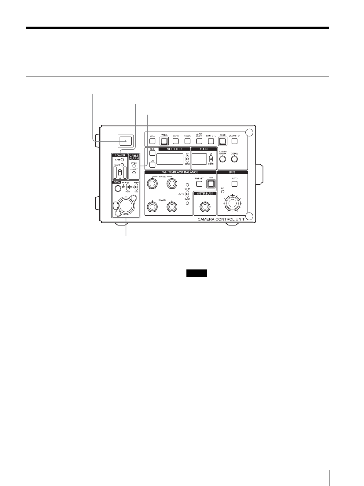
Front panel
a Camera number sheet/tally indicator
b POWER switch/CAM and MAIN indicators
c CABLE ALARM indicators
d INCOM input/output/setting section
a Camera number sheet/tally indicator
Lights red when the red tally signal is input (e.g. when
the video signal from the video camera connected to the
CCU-TX50/50P goes on air). When the CALL button
on the unit or RCP-D50 remote control panel is pressed,
the indicator lights red if it is not lit, and goes off if it is
lit.
The indicator lights green when the green tally signal is
input.
Attach the supplied number sheet here to indicate the
camera number.
b POWER switch/CAM (camera) and MAIN
indicators
The POWER switch turns on or off the power supply to
the entire camera system, including the CCU-TX50/
50P, the video camera, and the remote control unit
connected to the REMOTE connector on the CCUTX50/50P.
The MAIN and CAM indicators light when the POWER
switch is turned on.
The CAM indicator goes off when the power is turned
off by the CAM PW button on the remote control panel.
Note
If the fan in the CCU-TX50/50P stops, the MAIN
indicator will flash simultaneously to warn you of the
abnormal condition. If this occurs, turn the POWER
switch off immediately and contact Sony service
personnel.
c CABLE ALARM indicators
OPEN: Lights when no triaxial cable is connected to
the CAMERA connector on the rear panel of the
CCU-TX50/50P, or when the load current is
extremely low even when a camera cable is connected.
SHORT: Lights when there is a current overflow in
the triaxial cable.
d INCOM (intercom) input/output/setting section
INCOM (intercom) connector (XLR, 5-pin)
Connects a headset.
INCOM level control
Adjusts the input level of the headset.
MIC/PGM (program audio) switch
ON: Turns on the headset microphone.
Function and Location of Parts and Controls
5
Page 6
OFF: Turns off the headset microphone.
PGM: Outputs the program audio. When this position
is selected, the INCOM level control adjusts input
level of the program audio.
INCOM selector
Selects the pathway of intercom signals output/input
through the INCOM connector.
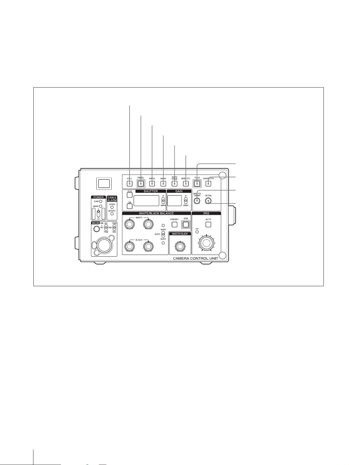
e CALL button
f PA N E L b ut t on
g BARS button
PROD: Producer line.
PRIV: Producer line and engineer line are cut off and
communication is possible only between the CCUTX50/50P and the camera connected to the rear panel
of the CCU-TX50/50P.
ENG: Engineer line.
h 5600K button
i AUTO KNEE button
j SKIN DTL button
k TLCS button
l CHARACTER button
m MASTER GAMMA
adjustment knob
n DETAIL adjustment knob
e CALL button
When you press this button, the TALLY indicator on the
camera adaptor lights. The tally indicator on the unit
also lights red when you press this button, and goes off
if the CALL button is pressed while it is lit.
f PANEL button
When the RCP-D50 camera control panel is connected,
press this button to light it up so you can select the
device which controls the camera.
The unit can control the camera when this button is lit.
g BARS button
Press this button (which lights up when pressed) to send
the color bar signal to the monitor. The color bars then
appear on the monitor.
6
Function and Location of Parts and Controls
h 5600K button
Press this button (which lights up when pressed) to
convert the color temperature electronically instead of
using the optical filter.
i AUTO KNEE button
Press this button (which lights up when pressed) to
activate the automatic knee function which optimizes
the input signal compensation.
j SKIN DTL button
Use this button to turn the skin detail correction function
on or off. Press this button (which lights up when
pressed) to set the skin detail correction function to on.
To set this function to off, press this button again.
k TLCS (total level control system) button
Press this button to turn the total level control system on
or off. When this button is lit, it is turned on, and settings
Page 7

made with the GAIN control section and SHUTTER
setting section are ignored.
changes to the next page. When this button is not lit, the
self-diagnostics screens are not displayed.
l CHARACTER button
Press this button (which lights up when pressed) to
display the self-diagnostics screen on the picture
monitor. Each time you press this button, the screen
o SHUTTER setting section
m MASTER GAMMA adjustment knob
Use this knob to adjust the gamma curve.
n DETAIL adjustment knob
Use this knob to adjust the detail level.
p GAIN control section
q WHITE/BLACK BALANCE setting section
r MASTER BLACK
adjustment knob
o SHUTTER setting section
Selects a shutter setting.
Note
This section does not function when the TLCS button is
on.
CLS button
Press this button (which lights up when pressed) to
activate the clear scan function.
ON button
Press this button (which lights up when pressed) to
activate the normal shutter function.
UP/DOWN selector
When the CLS button lights: The clear scan frequency
is increased, each time you press this selector to the UP
position. The clear scan frequency is reduced, each time
you press this selector to the DOWN position.
When the ON button lights: The shutter speed is
increased, each time this selector to the UP position. The
shutter speed is reduced, each time you press this
selector to the DOWN position.
s IRIS setting section
Display
Displays the clear scan frequency when the CLS button
lights, or the shutter speed when the ON button lights.
p GAIN control section
Adjusts the gain to obtain the most appropriate level for
the lighting condition.
UP/DOWN selector
The gain is increased, each time you press this selector
to the UP position. The gain is decreased, each time you
press this selector to the DOWN position.
Display
Displays the gain values in decibel units.
Function and Location of Parts and Controls
7
Page 8

q WHITE/BLACK BALANCE setting section
A WHITE controls
r MASTER BLACK adjustment knob
Adjusts the master black levels of the R, G, and B
signals simultaneously. The click position of the knob
provides a typical setting.
B PRESET button
C BLACK controls
D AUTO WHITE/BLACK switch
E ATW bu t t on
A WHITE (white balance manual adjustment)
controls
Turn these controls to manually adjust the white
balance. The left-hand control adjusts the R signal level
and the right-hand control adjusts the B signal level.
B PRESET button
Press this button (which lights up when pressed) to set
the white balance to the preset value. When this button
is lit, the operation of the AUTO WHITE section of the
AUTO WHITE/BLACK switch is ignored.
C BLACK (black balance manual adjustment)
controls
Turn these controls to manually adjust the black balance.
The left-hand control adjusts the R signal level and the
right-hand control adjusts the B signal level.
s IRIS setting section
A EXT indicator
B AUTO button
C IRIS control
A EXT (extender) indicator
Lights when a lens extender is being used on the video
camera.
B AUTO button
Press this button (which lights up when pressed) for
automatic adjustment of the iris. This button lights when
the automatic adjustment is in progress. Press this button
again to manually adjust the iris.
C IRIS control
Adjusts the iris manually when the AUTO button is set
to off. When the AUTO button lights, you can turn this
control to change the reference value for the automatic
iris adjustment.
D AUTO WHITE/BLACK (white balance/black
balance automatic adjustment) switch
Activates the automatic adjustment of the white balance
and black balance.
WHITE: Adjusts the white balance automatically one
time when the switch is set to this position.
BLACK: Adjusts the black balance automatically one
time when the switch is set to this position.
E ATW (auto tracing white balance) button
Press this button (which lights up when pressed) to have
the white balance adjusted automatically when lighting
conditions change.
8
Function and Location of Parts and Controls
Page 9

Rear panel
a CAMERA connector
b AUDIO OUTPUT connectors
c INPUT connectors
d OUTPUT connectors
e REMOTE connector
g MIC REMOTE connector
f INTERCOM/TALLY/PGM connector
a CAMERA connector (triaxial connector)
Connects to the CA-TX50/50P Camera Adaptor
attached to the DXC-D50 Color Video Camera using a
triaxial cable.
Caution
Do NOT use a defective triaxial cable.
The inner sheath of a triaxial cable is used for power
supply and the outer sheath for safety ground.
For your safety, do NOT use a triaxial cable whose inner
and outer sheaths are short-circuited. Use of such a cable
will cause electric shock.
b AUDIO OUTPUT connectors (XLR, 3-pin)
Supply audio signals from the video camera.
i AC IN connector
h WF MODE connector
connector is terminated automatically with an
impedance of 75 ohms.
A REFERENCE INPUT connectors
B RET-1/RET-2 connectors
C RET-3/PROMPTER connectors
c INPUT connectors
The two connectors of each pair are loop-through
connectors. When the upper connector is used and no
connection is made to the lower connector, the upper
D COAX connector
Function and Location of Parts and Controls
9
Page 10

A REFERENCE INPUT connectors (BNC type)
Accept reference signals (black burst signal) for external
synchronization.
B RET-1/RET-2 (return video signal 1/2)
connectors (BNC type)
Accept return video signals from two different systems.
For details on the selection of RET-1 and RET-2, refer to
Operation Manual that came with the camera or camera
adaptor.
C RET-3/PROMPTER (return video signal 3/
prompter) connectors (BNC type)
Accept a return video signal or a teleprompter signal.
For details on the selection of RET-3, refer to Operation
Manual that came with the camera or camera adaptor.
To set this connector to the PROMPTER output, it is
required to change the setting in the internal board.
B Y/G, R-Y/R, B-Y/B (component video signal /
RGB output) connectors (BNC type)
Supply the component signals or the R, G, and B signals
for the chroma keyer from each connector.
Use the switch on the internal board to select the signals
to be output.
For details on the internal boards, consult your nearest Sony
dealer.
C PIX (picture monitor output) connector (BNC
type)
Supplies a video signal or video and character signals
together to a picture monitor.
When using the RCP-D50 Remote Control Panel, you
can select the signal output from the PIX connector
using the MONITOR SELECT button on the menu of
the RCP-D50. When the signal output from the PIX
connector changes, the waveform output on the
waveform monitor also changes.
For details on the internal boards, consult your nearest Sony
dealer.
D COAX (coaxial) connector (BNC type)
Accepts and supplies signals from/to the video camera
using a coaxial cable. Power is not supplied to the
camera and a camera adapter through this connector.
To use this connector, it is required to change the setting of the
internal board. For details, consult your nearest Sony dealer.
d OUTPUT connectors
A VBS/SDI-1/VBS/SDI-2/VBS/SDI-3
connectors
B Y/G, R-Y/R, B-Y/B connectors
C PIX connector
D SYNC connector
E WF connector
A VBS/SDI-1/VBS/SDI-2/VBS/SDI-3 (composite
video signal 1/2/3 output) connectors (BNC type)
Supply the signal from the video camera in composite or
SDI format.
Use the switch on the internal board to select the signals
to be output.
For details on the internal boards, consult your nearest Sony
dealer.
D SYNC connector
Connect to the synchronous signal input connector on a
waveform monitor or picture monitor
E WF (waveform monitor output) connector (BNC
type)
Supplies a video signal to a waveform monitor.
When using the RCP-D50 Remote Control Panel, you
can select the signal output from the PIX connector
using the MONITOR SELECT button on the menu of
the RCP-D50. Changing the signal output from the WF
connector simultaneously changes the picture on the
picture monitor.
e REMOTE (RCP (remote control panel) remote)
connector (10-pin)
Connects to the RCP-D50 Series Remote Control Panel
with an optional CCA-7 connecting cable to transmit/
receive control signals.
f INTERCOM/TALLY/PGM (program audio)
connector (D-sub, 25-pin)
Inputs/outputs intercom, tally, or program audio signals.
Connects to an intercom, tally, or program audio
connector of an intercom system.
g MIC REMOTE (microphone remote control)
connector (D-sub, 15-pin)
Connects to an external control unit such as an audio
mixer. With the connected unit, you can set the
microphone input level of the video camera to –60, –50,
–40, –30, or –20 dB.
h WF MODE (waveform monitor mode)
connector (4-pin)
Connects to the corresponding connector on a waveform
monitor to allow the sequential monitoring of signals.
10
Function and Location of Parts and Controls
Page 11

i AC IN (AC power input) connector
Connects to an AC power source using the supplied AC
power cord. Secure the power cord to the CCU-TX50/
50P using the supplied plug holder.
Function and Location of Parts and Controls
11
Page 12

Connecting the CCU-TX50/50P to the Video Camera
When connecting a CCU-TX50/50P to a DXC-D50
Color Video Camera, you must first attach the CATX50/50P Camera Adaptor to the video camera.
CA-TX50
Triaxial cable
DXC-D50
CCU-TX50/50P
To an AC power source
Notes on connections
Triaxial cable
The triaxial cable should never be connected to or
disconnected from the CCU-TX50/50P when the power
is turned on. Always turn the unit off first.
Video camera
Some switches or controls on the video camera may not
work when the camera is connected to the CCU-TX50/
50P.
For details, refer to Operation Manuals of the video camera
and the camera adaptor.
12
Connecting the CCU-TX50/50P to the Video Camera
Page 13

Self-Diagnostics
The unit allows you to display the status of the unit and
the results of a self-diagnosis is of the internal boards of
the unit on the screen of a picture monitor connected to
the unit.
You can display the following status items:
• Settings of the camera
• Status display of the unit
• Results of a self-diagnosis of the internal boards
• Self-diagnostics of the camera system
Entering the Self-diagnostics Mode
The unit enters the self-diagnostics mode, by pressing
the CHARACTER button on the front panel of the unit.
Each time you press the CHARACTER button, the
display changes.
CHARACTER button
Settings of the Camera
The settings and operations status of the camera are
displayed.
Setting change and adjustment
progress message display area
1 Master gain
2 “4:3” is displayed when the images recorded in 16:9
format are output after converted to the images of
the 4:3 mode.
3 “EVS” is displayed when EVS of the electrical
shutter is on.
4 Shows the shutter speed currently selected.
5 Shows the on/off setting of the shutter.
6 Shows the type of ND filter currently selected.
7 Shows the F-stop (iris setting) of the lens.
8 EX is displayed when a lens extender is used.
Status Display of the Unit
Press the CHARACTER button when the screen of the
camera settings is displayed. The status of the unit is
displayed.
DXC-D50: Model name and format of the connected
camera
Self-Diagnostics
13
Page 14

CCU-TX50: Model name and format of the camera
control unit connected.
Genlock: External reference signal and its status
(lock/unlock)
Prompter: Transmission direction of the prompter
line
Return 1 to 3: Return video signal input status
Self-diagnostics of the Camera System
Press the CHARACTER button when the status display
of the unit is displayed. Page 1 of the self-diagnostics
display is displayed.
The results of a self-diagnosis of the camera system are
displayed spread over three pages.
Page 1
Page 2
CAMERA cable: Camera cable connection status
(connected/shorted)
CAMERA Data: Camera data transmission status
CAMERA Power: Status of the power supply to a
camera
CAMERA Tone: Camera ID tone status
RCP cable: Connection status of the REMOTE
connector
RCP Data: Data transmission status of the REMOTE
connector
RCP Power: REMOTE connector power supply
status
TRIAX TYPE: Type of Triaxial circuit
TRIAX Cable: Triaxial cable connection status
(connected/disconnected)
TRIAX Comp.: Cable compensation type selected
for the triaxial cable (automatic/manual)
TRIAX Step: Compensation step of the triaxial cable
(step indication in the circuit) (The cable length may
not be displayed correctly.)
Fan power: Fan status in the CCU power block
Timer: Power up time to devices connected
CCU Power: Status of the CCU power supply
Page 3
Intercom CCU: CCU intercom selection (system/
private)
Intercom CAMERA CH1: Status of intercom 1 of a
camera (producer line/engineer line)
CHU MIC Gain: Gain and control status of the
microphone circuit
Results of the Self-diagnosis of the
14
Internal Boards of the Unit
Press the CHARACTER button when page 3 is
displayed. Page 1 of the results of the self-diagnosis of
the internal boards is displayed.
Self-Diagnostics
Page 15

Each time you press the CHARACTER button, another
page of results is displayed in turn.
DM board
CAM Video: Reception status of the video signals
from the camera.
Skin Gate: Reception status of the Skin gate signal
from the camera
TRIAX Comp.: Cable compensation type selected
for the triaxial cable (automatic/manual)
TRIAX Step: Compensation step of the triaxial cable
(step indication in the circuit) (The cable length may
not be displayed correctly.)
Power: DM board power supply status
AT boa r d
Reference: Operation mode of the phase adjustment
Gen Lock: Locking status
BATT Volt: Voltage of the coin battery supplied with
the AT board
CCU Mode: Operation mode of the CCU
PLD Config.: Configuration result status of the PLD
mounted on the AT board
CCU Power: CCU power supply type (AC/DC) and
power supply status
AU board
TR board
Prompter: Setting status of the prompter line
To ne : Tone signal status
Incom: Demodulating status of the intercom line
CHU Data: Data reception status from the camera
Power: Power supply status of the TR board
CAMERA MIC: Input status of the camera
microphone (on/off)
CAMERA LINE: Pathway of the intercom signal of
the camera (ENG/PROD/PRIV)
CCU FRONT MIC: Input status of the unit’s
microphone (on/off)
CCU FRONT LINE: Pathway of the connection of
the intercom signal of the unit (ENG/PROD/PRIV)
POWER: Power supply status of the AU board
Self-Diagnostics
15
Page 16

IV board
Diagnostics Page of the Camera
Return: Setting status of the return signal input
connectors to the return channels from 1 to 3
Return Signal: Status of the return video input signal
Rear CN: Power supply status of the CN board on the
rear
PLD Config: Configuration completion status of the
PLD mounted on the IV board
Power: Power supply status of the IV board
EN board
Component: Setting status of the component output
signal from the OUTPUT connector and status of the
sync signal added to the component Y/G output signal
from the OUTPUT connector
Composite Out-1: Signal type from composite output
connector 1 (VBS/SDI)
Composite Out-2: Signal type from composite output
connector 2 (VBS/SDI)
Composite Out-3: Signal type from composite output
connector 3 (VBS/SDI)
Composite Setup: Setup settings to be added to the
VBS signal
Rear VDA: Power supply status of the VDA board on
the rear
PLD Cofig: Configuration completion status of the
PLD mounted on the EN board
Power: Power supply status of the EN board
The results of the diagnosis of each board of the camera
are displayed.
Exiting the Self-diagnostic Mode
Display the last “ROM Version” page, and then press the
CHARACTER button again.
When an Error Occurs
The error message is displayed on the picture monitor. In
such a case, display the self-diagnostics page
corresponding to the board where the error has occurred
by pressing the CHARACTER button.
16
Self-Diagnostics
Page 17

Notes on Use
Specifications
Use and storage locations
Avoid using or storing the unit in the following places:
• Where it is subject to extremes of temperature
(operating temperature: +5ºC to +40ºC (41ºF to
104ºF)).
Note that in summer the temperature in a car with the
windows closed can reach 50ºC (122ºF).
• Very damp or dusty places.
• Where rain is likely to reach the unit.
• Places subject to severe vibration.
• Near strong magnetic fields
Near transmitting stations generating
strong radio waves.
Avoid violent impacts
Dropping the unit, or otherwise imparting a violent
shock to it, is likely to cause it to malfunction.
Do not cover with cloth
While the unit is in operation, do not cover it with a cloth
or other material. This can cause the temperature to rise,
leading to a malfunction.
After use
Turn the POWER switches on the unit and camera
control unit off.
Care
If the body of the unit is dirty, wipe it with a dry cloth.
For severe dirt, use a soft cloth steeped in a small amount
of neutral detergent, then wipe dry. Do not use volatile
solvents such as alcohol or thinners, as these may
damage the finish.
General
Power consumption
100 - 240 V AC, 50/60 Hz,
maximum 1.3 A
Peak inrush current
(1) Power ON, current probe method:
50 A (240V)
(2) Hot switching inrush current,
measured in accordance with
European standard EN55103-1:
10 A (230V)
Cable length Maximum 750 m (φ 8.5 mm)
Operating temperature
+5ºC to +40ºC (41ºF to 104ºF)
Dimensions 200 × 124 × 365 mm
(8 × 5 × 13 7/8 in.) (w / h / d)
not including projecting parts
Mass Approx. 5.5 kg
Input signals
REFERENCE BNC type (loop-through)
VBS/BS, 1.0 Vp-p, 75 ohms automatic
RET-1/2/3
PROMPTER
1) The same signal is input to RET-3 and PROMPTER.
1)
terminated
BNC type (1 each, loop-through)
VBS, 1.0 Vp-p, 75 ohms automatic
terminated
1)
BNC type (loop-through)
VBS, 1.0 Vp-p, 75 ohms
Output signals
VBS 1/2/3 BNC type (1 each)
VBS, 1.0 Vp-p, 75 ohms
SDI BNC type (3)
SDI format, 270 Mbps, SMPTE 259M
(CCU-TX50)/CCIR656-III (CCU-
TX50P)
Y/R-Y/B-Y video
R/G/B video
PIX BNC type (1)
WF BNC type (1)
2)
BNC type (1 each)
Y: 1.0 Vp-p, 75 ohms
R-Y/B-Y: U.S.A. and Canada:
700 mVp-p, 75 ohms
Europe: 525 mVp-p, 75 ohms
2)
BNC type (1 each)
700 mVp-p, 75 ohms
1.0 Vp-p, 75 ohms
NTSC: 714 mVp-p, 75 ohms
Notes on Use / Specifications
17
Page 18

PAL: 700 mVp-p, 75 ohms
Encoded output: 1.0 Vp-p, 75 ohms
WF MODE 4-pin (1)
AUDIO OUTPUT
XLR, 3-pin
0 dBu/–20 dBu, balanced, 2 channels
SYNC BNC type
2) R/G/B/and Y/R-Y/B-Y are switchable.
Camera input/output signals
CAMERA Triax (Kings type for the U.S.A.
and Canada, Fischer type for Europe)
COAX BNC type (1), 75 ohms
REMOTE 10-pin, multi connector
INTERCOM/TALLY/PGM
D-sub, 25-pin (1)
4W/RTS
TALLY: 24 V DC, TTL level or
contact selectable
MIC REMOTE D-sub, 15-pin (1)
INCOM (on the front panel)
XLR, 5-pin (1)
Supplied accessories
AC power cord (1)
AC power plug holder (1)
Number plate (1 set)
Operating Instructions (1)
CD-ROM (including multi-lingual operating
instructions) (1)
Warranty booklet (1)
Optional accessories
Remote Control Panel RCP-D50
Rack Mount Bracket RMM-301
Design and specifications are subject to change without
notice.
18
Specifications
Page 19

Sony Corporation
 Loading...