

Page 1

Network Video Surveillance
CCIR/PAL
Issued July 1999
Page 2

1
Introduction
The Total Survillance System Solution from Sony 2
Case studies from around the world 4
Sony Camera, Monitor and Time - Lapse VCR Technologies - The Sony Advantage
6
Colour Cameras and Monitors - Quick Reference 9
Colour Video Cameras
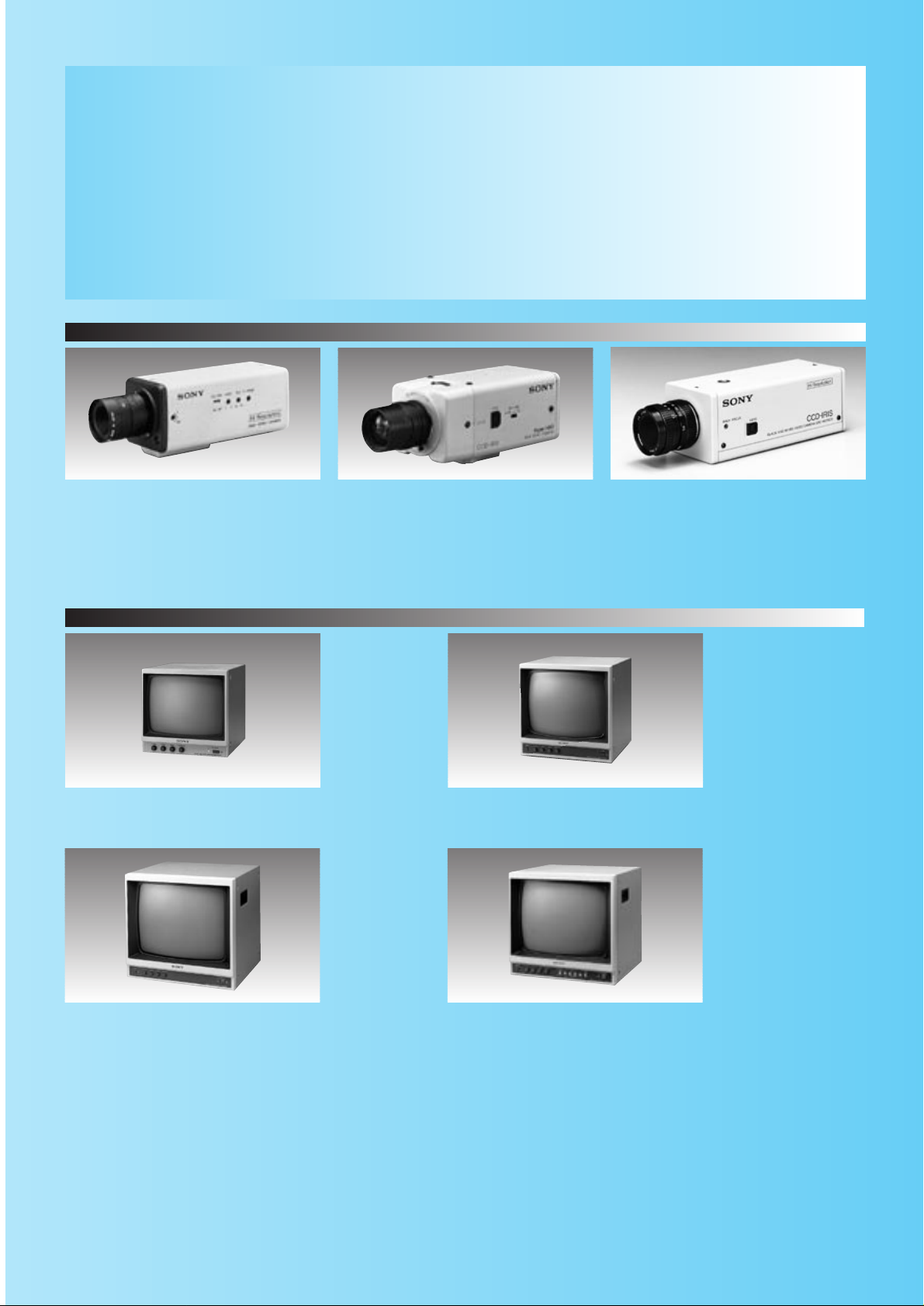
SSC-CX34P 10
SSC-DC50AP/DC54AP/DC58AP 12
SSC-DC10P 14
SSC-DC14P/DC18P 14
SSC-C108P/C104P 15
SSC-C370P 16
Colour Cameras Typical System 17
Colour Camera Specifications 18
Colour Video Monitors
SSM-9040P 20
SSM-14N5E/14N5A 20
SSM-20N5E/20N5A 21
Colour Monitor Specifications 22
Black & White Cameras and Monitors - Quick Reference 23
Black & White Video Cameras
SPT-M308CE/M304CE 24
SPT-M122CE/M124CE/M128CE 24
SSC-M370CE 25
B/W Cameras Typical System 26
B/W Camera Specifications 28
Black & White Video Monitors
SSM-930CE 29
SSM-125CE 29
SSM-175CE 30
SSM-Q177CE 30
Camera Optional Accessories - Quick Reference 31
Camera Adaptors 32
Lenses 33
Cables 34
Mounting Brackets 34
•Sony is a registered trademark of Sony Corporation.
•“Exwave HAD”, “Super HAD”, “0 Lux Shot”, “CCD IRIS”, “Hyper HAD”,
“HAD sensor”, “Smart Control” and “Turbo AGC” are trademarks of Sony Corporation.
•Features and specifications subject to change without notice.
Contents
Multiplexers and Switchers - Quick Reference 35
YS-DX316P/YS-DX216CE 36
YS-SX310P/YS-SX210CE 38
YS-S6 40
YS-Q440P 41
Time Lapse Video Recorders - Quick Reference 43
SVT-L230P 44
SVT-124P 45
SVT-1000P 46
SVT-S3050P 47
SVT-5050P 48
Analog Time Lapse VCR Feature Comparison Chart 49
HSR-1P 50
Optional Accessories 51
Monitoring Codecs and System Controller
- Quick Reference 53
PMS-500P/400P 54
CSP-5000E 56
Printers - Quick Reference 59
Colour Video Printers
Feature Comparison Charts 60
UP-5600MDP 61
UP-2850P/2800P 62
UP-2300P/2100P 63
Black & White Video Graphic Printers
UP-960CE 64
UP-890CE 65
Video Printer Optional Accessories 66
Digital Colour Printer
UP-D6500/D6400/D6300 67
Automotive Camera and Monitors - Quick Reference 69
Black & White Video Camera
SSC-534AM 70
Black & White Video Monitors
SSM-504AM/724AMR 71
Glossary 72
Product Index 74
Major Security Product Shows '99
Show Date Place
Asia
ASIA Security 99 Aug. 10-12 Melbourne
Security China Oct. 26-29 Shenzhen
Securex China Dec. 1-4 Shanghai
Central and South America
Expo Securidad Mexico City June 14-16 Mexico City
Securitech Argentina July 6-8 Buenos Aires
Expo Security Brazil Nov 17-19 Sao Paulo
Show Date Place
Europe
IFSEC May 10-13 Birmingham
Alarmes Protection Securite 99 Oct 6-8 Paris
SiTech 99 Oct 27-30 Berlin
North America
ISC-EAST Aug 31-Sept 2 New York
ASIS Sept 27-30 Las Vegas
CANASA CENTRAL Oct 20-21 Toronto
Page 3

TheTotal Surveillance System Solution from
2
Sony continues to expand its line up of products and new technologies in order to give you the most
effective surveillance and monitoring system possible. Versatile, high quality video equipment,
backed up by a world wide sales and service network make Sony the obvious choice for your video
surveillance needs. When it comes to surveillance, look no further than Sony.
Monitor
Multiplexer
Monitoring Codec
Analog VCR
Printer
Switcher
Digital VCR
Monitor
Camera
Camera
Page 4

3
Sony
Surveillance system applications
Convenience store/Retail surveillance
System configuration example
SPT-M128CE camera SSM-930CE monitor YS-S6 switcher SVT-124Ptime-lapse VCR -
Remote facility monitoring
System configuration example
PMS-500P monitoring codec SSC-DC58AP camera Computer monitor SVT-1000Ptime-lapse VCR -
Bank surveillance
System configuration example
SSC-DC18P camera SSM-20N5E/20N5A monitor HSR-1P digital time-lapse VCR -
Transportation/Train station surveillance
System configuration example
SSC-DC58AP/DC18P camera SSM-14N5E/14N5A monitor YS-DX316P multiplexer SVT-S3050Ptime-lapse VCR -
ISDN
Page 5

4
Case studies from around the world
Portugal Expo'98
Expo'98 in Lisbon, Portugal hosted 150 countries and in four
months a total of 10 million people visited the two million square
metre site. The highest attendance was 380,000 visitors passing
through the site on the Expo's last day. In this environment
surveillance and security are critical issues, and Sony took over
the role of prime contractor with sole responsibility for project
execution, equipment supply, system installation and
maintenance during Expo'98's four month open period.
Sony installed a
network of
43 high-performance
surveillance cameras,
all with pan & tilt
capabilities suited to
outdoor operation.
The monitoring centre
had at its heart a
control and switching
system based on the
new Sony CSP-5000
matrix switcher and a
total of 24 Sony CCTV
colour monitors. A basic requirement of the system was for
continuous 24-hour recording of all incoming images.
To achieve this, Sony used five S-VHS SVT-S3050P time-lapse
VTRs and five top of the range colour multiplexers (YS-DX316P).
The network of cameras was connected to the control room
using more than 60km of copper wire and 10km of optical fibre.
All the images entering the control room were fed in to three
Sony CSPK-5000 matrix keyboards, and these pictures were
relayed to another control room where the security department's
controller could watch all the public areas on six Sony monitors.
Despite daily temperatures of up to 43 degrees Celsius, the
system never failed during the four month period of Expo'98.
City of Mississauga,
Ontario Canada
At the City of Mississauga, keeping residents secure is a top
priority. Canada's sixth largest city, located west of Toronto, is in
the midst of installing a comprehensive video surveillance
system. By the time the project is complete, more than 100
closed-circuit television (CCTV) cameras will have been installed
at strategic locations throughout the city - at transportation
works yards, transit yards, community centres, libraries, parking
lots, swimming pools and bus depots.
Cameras chosen for the job were Sony SSC-DC14 and
SSC-DC54A digital colour cameras. The high resolution and
sensitivity of the cameras yield high-quality images even in
adverse lighting conditions.
The Sony SSC-DC54A capitalizes on its advanced 1/2-inch
Exwave HAD CCD chip to deliver exceptional colour accuracy
with 470 lines of horizontal resolution. Small enough to be used
in the most demanding circumstances, the chip maximizes
sensitivity, reduces smear and significantly increases S/N levels.
For Control Centre monitoring, the City of Mississauga has
installed six Sony SSM-20N1U Trinitron colour monitors.
The 20-inch versatile, rack-mountable units offer more than 500
lines of horizontal resolution for sharp pictures and auto beam
current feedback for colour stability. Built-in speakers permit
audio monitoring, and on-screen prompting provides easy,
user-friendly operation.
Page 6

5
Gelredome, The Netherlands
The Arnhem Gelredome was fitted with a security system
in which Sony equipment plays the central role. There are
35 SSC-DC18P cameras located both inside the stadium
and outside - in the promenade areas, above the stands,
above the parking areas - all linked to 14" and 20"
monitors, allowing instant playback of recorded images.
The 20" monitors are used with colour quad units in the
control room, manned by the police and Gelredome staff.
This allows images from 16 cameras to be monitored
simultaneously and permits any selected picture to be
displayed onto a spot monitor for further study at any
time. Three Sony time-lapse recorders ensure continuous
recording and the Sony video printers provide printouts
direct from the video. This makes surveillance, detection
and follow-up easy and efficient.
Mycal Akashi, Akashi Japan
Mycal Akashi is a 150,000 square meter complex
consisting of a number of department stores, restaurants,
sports facilities and movie theaters. The buildings and
parking lots of this complex are kept safe and secure
thanks to 50 cameras which are centrally controlled by
the Sony CSP-5000 System Controller. The cameras are
strategically located through out the buildings and out door parking lots. Moreover, four cameras on the roof can
monitor traffic 4 to 5 km beyond the complex.
Since implementing this surveillance system, security
staff have been able to respond more quickly to
problems such as a group of trouble-makers indoors, as
well as monitor traffic and parking more effectively
outdoors. This monitoring system also has made labor
saving possible during night shift hours.
Norddeustsche Landesbank,
Germany
Security is essential to all organisations but none more
than banks. With cash dispensers throughout the world
needing surveillance around the clock, security
requirements are pushed to the limits. That’s why a
German bank giant, The Norddeutsche Landesbank,
installed Monitoring Codecs in several of its branches.
It’s a system developed by Sony that gives multi-site
two-way surveillance from a single central location. And
by using the latest ISDN technology it’s possible to
prevent crimes as and when they happen.
Page 7

Smart Control
(SSC-DC10P/14P/18P/50AP/54AP/58AP/CX34P)
Strong backlighting can often cause the subject of the
picture to be cast into shadow. To overcome this
problem, Smart Control achieves the optimum balance
between Iris and Gain settings in a unified digital signal
processing circuit. As a result, clear colour images can
be obtained even under severe or varying lighting
conditions. Smart control also works intelligently as it
employs average light metering to detect the position of
the major subject, and Fuzzy Logic to calculate the
proper exposure.
Monitor technology
Trinitron CRT
Sony incorporates Trinitron CRTs in all of its surveillance
colour monitors.With its completely original design, the
Trinitron technology allows for high resolution and the best
possible picture reproduction. The completely flat, straight
vertical surface of the Trinitr on CRT provides the lowest
purity imperfection available with the CRT technologies of
today. Moreover, Sony manufactures its own CRTs to assure
quality performance in all of its monitors.
6
Camera technologies
Exwave HADTM(SSC-DC50AP/54AP/58AP)
In monitoring and surveillance applications, camera
sensitivity is one of the most important factors in
obtaining an adequate picture in low light conditions.
The sensitivity of Sony cameras using the Exwave
HAD CCD is well over twice that of the cameras using
the Sony Hyper HAD CCD. The Hyper HAD sensor
structure has an OCL (on chip lens) located over each
pixel. The result is that light is concentrated on the
photosensor areas and the sensitivity of the camera is
improved. The Exwave HAD takes the Hyper HAD sensor
technology a giant step further. The OCL of the Exwave
HAD CCD is a nearly gap-less structure, eliminating the
ineffective areas between the microlenses. This enables
the hole accumulated layer to receive the maximum
amount of light.
Moreover, the smear level of the Exwave HAD CCD is
reduced to 1/50th that of the Hyper HAD CCD.
This leakage is dramatically reduced because the
improvement of the unit cell structure minimizes the
unnecessary reflection of the light onto the CCD surface.
Ineffective area
Transfer register
Hole accumulated layer
Backlight Compensation
Digital Signal Processing Analogue Signal Processing
Hyper HAD CCD
Exwave HAD CCD
Sony Camera,Monitor and Time-lapseVCR
Page 8

7
Time-lapse VCR technologies
Hybrid Recording (HSR-1P)
The Sony HSR-1P digital time-lapse recorder uses both a
hard disk drive (HDD) and a DV (digital video) tape drive
for storage. The image data is first recorded onto the
HDD and is then transferred to DV tape. This "hybrid"
approach to recording has two major advantages.
The first advantage is reduced maintenance. Because
the DV tape drive works only while recording the image
data being transferred from the HDD, the tape transport
and heads are stationary most of the time.
This significantly reduces the need for head
maintenance. The second advantage is multiple
protection. In the unlikely event that the DV tape drive
fails, recording continues onto the HDD. Conversely, if
the HDD fails, recording continues on the DV tape.
APC (Adaptive Picture Control)
As the recording heads of VCRs become worn after
extended use the picture quality will deteriorate unless
the recording current is adjusted accordingly. All Sony
SVT time-lapse VCRs have an APC (Adaptive Picture
Control) function which automatically detects the
condition of the recording head and the video cassette
tape, then sets the optimum record head current. With
conventional recorders the recording current is preset at
a constant level, which results in an excessive recording
signal as the VCR heads become worn. This is called
over-modulation. APC maintains the recording current at
the ideal level, preventing over-modulation and therefore
recording clear pictures even after long periods of use.
RealAction Recording (SVT-L230P)
The SVT-L230P time lapse VCR features RealAction high
density recording. For example, conventional time lapse
VCRs record only 5.5 fields per second in 24 hour
recording mode. However, Sony RealAction technology
allows recording of 16.6 fields per second - three times
as much information. This recording density ensures
smooth, natural recording of even fast moving objects.
Conventional VCR
Time
*1
*3
Recording Current
*1
*3
VCR with APC
*1 Ideal recording current *1 Ideal recording current
*2 Preset recording current *3 APC recording current
(A) Excessive recording current
(over-modulation)
RealAction recording 16.6 fields/sec.
Normal time-lapse recording 5.5 fields/sec.
DV Tape Drive
Hard Disk Drive
DV Signal Transfer
<HSR-1 Recording Process>
Technologies - The Sony Adv antage
(A)
*1
Recording Current
*1
*2
*2
Time
Page 9

9
SSC-DC50AP/54AP/58AP
1/2-inch Exwave HAD CCD
High resolution
Smart Control
DC 12 V or multiplexing with YS-W150P/W250P
(SSC-DC50AP)
AC 24 V, 50 Hz (SSC-DC54AP)
AC 220 to 240 V, 50 Hz (SSC-DC58AP)
SSC-CX34P
1/3-inch Hyper HAD CCD
Built-in 12x zoom lens
Remote lens control capability
High resolution
Smart Control
Quick Reference
COLOUR CAMERAS AND MONITORS
The selection of high quality surveillance cameras and monitors from Sony is better than
ever. Sony cameras now incorporate more features and superior technology such as the
highly sensitive Exwave HAD CCD used in the SSC-DC50AP series cameras.
Sony monitors use the Emmy award winning Trinitron technology, providing clearly
defined, high quality images that are vital for effective surveillance.
SSC-DC10P/DC14P/DC18P
1/3-inch Hyper HAD CCD
High resolution
Smart control
DC 12 V or multiplexing with YS-W150P/W250P
(SSC-DC10P)
AC 24 V, 50 Hz (SSC-DC14P)
AC 220 to 240 V, 50 Hz (SSC-DC18P)
SSC-C108P/C104P
1/3-inch Hyper HAD CCD
High S/N ratio
AC 220 to 240 V, 50 Hz (SSC-DC108P)
AC 24 V, 50 Hz (SSC-DC104P)
SSM-9040P
Trinitron 9-inch monitor
Colour Cameras
Colour Monitors
SSC-C370P
1/2-inch Hyper HAD CCD
High resolution
DC12 V or multiplexing with YS-W150P/W250P
SSM-14N5E/14N5A
Trinitron 14-inch monitor
High resolution
SSM-20N5E/20N5A
Trinitron 20-inch monitor
High resolution
Page 10

12
COLOUR VIDEO CAMERAS
Built-in Zoom Lens Colour Video Camera
SSC-CX34P
•Especially designed for surveillance applications
•Built-in 12x switchable motorized/auto iris zoom lens
with zoom/focus preset capabilities
•The lens zoom, focus and iris functions can be remotely
controlled from an external controller/receiver
(Lens control voltage, ±6 V or ±12 V is selectable)
•
Digitally-controlled Smart Control function provides
intelligent and flexible automatic backlight compensation
•High density 1/3-inch IT Hyper HAD CCD offers a high
resolution of 470 TV lines and high sensitivity with a
minimum illumination of 4.5 lx at F1.8 (50 IRE)
•Excellent signal-to-noise ratio of 50 dB
•Extra gain with Turbo AGC function, providing 6 dB
more gain than conventional AGC
•Aperture/Sharp Mode makes object outlines sharper in
the reproduced picture
•Three alternative automatic white balance control
modes: AWB (Auto White Balance) by one push /ATW
(Auto Tracing White Balance)/ATWpro
•New ATWpro mode ensures reliable white balance
control based on the absolute colour temperature of the
object (The effective operational colour range is 2500 K
to 6000 K)
Supplied Accessories
Tripod adaptor (1)
Lens control cable (1)
Operation manual (1)
Lens Connector Information
3. Position Output Motion
Position voltage increase Position voltage decrease
Zoom Position output 3-pin
Tele side Wide side
Focus Position output 5-pin
Far side Near side
2. Lens Motion by NORM/REV switch
Switch NORM position Switch REV position
Focus In + Voltage Far Near
6-pin - Voltage Near Far
Zoom In + Voltage Wide Tele
7-pin - Voltage Tele Wide
Iris In + Voltage Close Open
8-pin - Voltage Open Close
Front Panel Rear Panel
1. Pin Assignments
Lens: 12 x zoom (f = 5.4 mm ~ 64.8 mm) (F1.8 to 2.7)
Angle of view (horizontal): 48.8°(Wide) ~ 4.3°(Tele)
Angle of view (vertical): 37.6°(Wide) ~ 3.3°(Tele)
Maximum object distance: 10 mm (Wide), 800 mm (Tele)
Focus: Manual
Lens control voltage: 6 V or 12 V selectable
Voltage polarity: NORMAL or REVERSE switchable
Focus/Iens control:
Preset function from external remote control system
Auto iris: ON/OFF switchable
Built-in Zoom Lens Specifications
Pin number
Name Meaning
Voltage spec
Supplied Cable Colour
1
Preset +
V1 = + Power for preset
12 Vp-p maximum
Red
2
Preset -
V2 = - Power for preset
12 Vp-p maximum
White
3
Zoom Position Out Zoom position voltage output
V2 to V1
Black
4
GND
––
Yellow
5
Focus Position Out Focus position voltage output
V2 to V1
Blue
6
Focus In
Focus control voltage input -12 V to +12 V
Green
7
Zoom In
Zoom control voltage input -12 V to +12 V
Brown
8
Iris In*
Iris control voltage input -12 V to +12 V
Grey
*Note: If Iris is in auto mode, this voltage control is not accepted.
Turbo
AGC
APERTURE
±
6V/±12V DC
w/potentiometer
EXT. LENS CONT.
876
4
5
3
21
X12
COLOUR
BUILT-IN LENS
Page 11

13
COLOUR VIDEO CAMERAS
SSC-CX34P Typical System
1.Analogue Pan/Tilt and Lens Controller System
2.Twisted Pair System
SSC-CX34P
OPTICAL
12X
ZOOM
Digital
Pan/Tilt
AC 24V
SSC-CX34P
OPTICAL
12X
ZOOM
Digital
Pan/Tilt
SSC-CX34P
OPTICAL
12X
ZOOM
Digital
Pan/Tilt
SSC-CX34P
OPTICAL
12X
ZOOM
Digital
Pan/Tilt
Lens control
(Voltage)
Pan/Tilt control
AC outlet
VIDEO OUT (Coaxial cable)
Lens control
(Voltage)
AC 24V
Pan/Tilt control
Receiver
(Preset type)
VIDEO OUT (Coaxial cable)
Lens control
(Voltage)
AC 24V
Pan/Tilt control
VIDEO OUT (Coaxial cable)
Lens control
(Voltage)
AC 24V
Pan/Tilt control
AC outlet
AC outlet
Receiver
AC outlet
Receiver
VIDEO OUT
(Coaxial cable)
Colour Video Monitor
Pan/Tilt & Lens Controller
Control
RS-485
RS-485
RS-485
System Controller
(Twisted Pair)
VIDEO OUT
(Coaxial cable)
Time Lapse VCR
Colour Video Monitor
VIDEO OUT
(Coaxial cable)
Pan/Tilt
SSC-CX34P
OPTICAL
12X
ZOOM
Digital
VIDEO OUT (Coaxial cable)
Lens control
(Voltage)
AC outlet
AC 24V
RS-485
Pan/Tilt control
Receiver
Page 12

5600K
Turbo
AGC
APERTURE
Exwave
14
COLOUR VIDEO CAMERAS
CCD Colour Video Camera
SSC-DC50AP/DC54AP/DC58AP
SSC-DC50AP SSC-DC50AP
SSC-DC50AP
SSC-DC54AP/58AP
•Especially designed for surveillance applications
•High density 1/2-inch IT Exwave HAD CCD offers
excellent sensitivity with a minimum illumination of 0.8 lx
at F1.2 (50 IRE), very low smear, and high resolution of
470 TV lines.
•
Digitally-controlled Smart Control function provides
intelligent and flexible automatic backlight compensation
•For faster backlight compensation, the detection area
can be preset
•Excellent signal-to-noise ratio of 50 dB
•Y/C output capability
•Extra gain with Turbo AGC function, providing 6 dB
more gain than conventional AGC
•Aperture/Sharp Mode makes object outlines sharper in
the reproduced picture
•Four alternative white balance control modes: AWB
(Auto White Balance) by one push/ATW (Auto Tracing
White Balance)/ATW pro/5600 K
•New ATW pro mode ensures reliable white balance
control based on the absolute colour temperature of the
object (The effective operational colour range is 2500 K
to 6000 K)
•Variable speed electronic shutter
•Accepts 2 types of auto iris lenses
(DC servo type/Video servo type)
•Accepts C/CS-mount lenses
Exclusive features for SSC-DC50AP
•External synchronization with VBS or VS
•Single cable operation (video/sync/power triple
multiplex transmission) for easy installation with the
optional YS-W150P/W250P Camera Adaptor (Mode A)
•Monitor out function for on-the-spot camera positioning
(Mode A)
•12 V DC power supply can also be used (Mode B)
Exclusive features for SSC-DC54AP/DC58AP
•External synchronization with VBS, VS or AC line lock
•AC power operation: AC24 V (DC54AP), AC220-240 V
(DC58AP)
Supplied Accessories
Lens connector (1)
Lens mount cap (1)
Operation manual (1)
Optional Accessories
Camera Adaptor (for SSC-DC50AP only) YS-W150P, YS-W250P
Manual Iris Lens VCL-S03XM (3.6 mm, F1.6)
VCL-S06XM (6.0 mm, F1.2)
VCL-S12XM (12 mm, F1.2)
Auto Iris Lens VCL-S03XEA (3.6 mm, F1.6)
VCL-S06XEA (6.0 mm, F1.2)
VCL-S12XEA (12 mm, F1.2)
Aspherical Auto Iris Lens
VCL-3ADXEA (3.8 mm, F0.8)
SSC-DC50AP
SSC-DC54AP
Rear Panel
SSC-DC54AP SSC-DC58AP
•Selectable eight detection area
Lens shown is an option
SSC-DC58AP
No.1No.0
No.2
No.3
No.4 No.5
No.6 No.7
COLOUR
8 AREA
AE SPOT
Page 13

VIDEO OUT
Time Lapse VCR
(ex.SVT-S3050P)
AC 24 V
power supply
AC outlet
(Coaxial cable)
VIDEO OUT
(Coaxial cable)
VIDEO OUT
(Coaxial cable)
VIDEO OUT
(Coaxial cable)
1. Triple multiplexing operation (SSC-DC50AP)
2. AC line lock operation (SSC-DC54AP/SSC-DC58AP)
3. VBS lock operation (SSC-DC50AP: DC 12 V/SSC-DC54AP: AC 24 V/SSC-DC58AP: AC 220-240 V)
4. Y/C output operation (SSC-DC50AP: DC 12 V/SSC-DC54AP: AC 24 V/SSC-DC58AP: AC 220-240 V)
SSC-DC50AP
SSC-DC50AP
SSC-DC50AP
SSC-DC50AP
(Coaxial cable)
(Coaxial cable)
(Coaxial cable)
(Coaxial cable)
AC outlet
Camera Adaptor
(YS-W250P)
Multiplexer
(ex.YS-DX316P)
VIDEO OUT VIDEO IN
VIDEO OUT
(Coaxial cable)
Time Lapse VCR
(ex.SVT-L230P)
DC POWER,
SYNC,VIDEO
DC POWER,
SYNC,VIDEO
DC POWER,
SYNC,VIDEO
DC POWER,
SYNC,VIDEO
(ex.SSM-20N5E)
Colour Video Monitor
VIDEO OUT
Distributor
VIDEO OUT
Splitter
SYN
VBS IN
VIDEO OUT
VIDEO OUT
Y/C OUT
Y/C OUT
Y/C OUT
Colour Video Printer
(ex. UP-2300P)
SSC-DC50AP/DC54AP/DC58AP
SSC-DC50AP/DC54AP/DC58AP
SSC-DC50AP/DC54AP/DC58AP
SSC-DC58AP
SSC-DC58AP
SSC-DC54AP
SSC-DC54AP
(ex.SSM-20N5E)
Colour Video Monitor
(ex.SSM-20N5E)
Colour Video Monitor
(ex.SSM-20N5E)
Colour Video Monitor
Multiplexer
(ex.YS-DX316P)
MONITOR OUT
(Coaxial cable)
MONITOR OUT
(Coaxial cable)
VIDEO OUT VIDEO IN
Time Lapse VCR
(ex.SVT-L230P)
(ex.SSM-20N5E)
Colour Video Monitor
(ex.SSM-20N5E)
Colour Video Monitor
Digital
Digital
Digital
Digital
Digital
Digital
Digital
Digital
Digital
Digital
Digital
AC outlet
AC outlet
AC outlet*
AC outlet*
AC outlet*
15
COLOUR VIDEO CAMERAS
SSC-DC50AP/DC54AP/DC58AP Typical Systems
Please see page 19, also.
*The SSC-DC50AP operates from a DC 12 V power supply,
the SSC-DC54AP from a AC 24 V power supply,
and the SSC-DC58AP from AC 220 to 240 V.
Page 14

16
COLOUR VIDEO CAMERAS
Turbo
AGC
APERTURE
CCD Colour Video Camera
SSC-DC10P
SSC-DC10P
SSC-DC10P SSC-DC10P
SSC-DC10P
Supplied Accessories
Lens connector (1)
Lens mount cap (1)
Operation manual (1)
Optional Accessories
Camera adaptor YS-W150P, YS-W250P
Auto iris lens VCL-4V8WEA (3.5 to 8.0 mm, F1.4)
VCL-S02WEAP (2.8 mm, F1.3)
Aspherical auto iris lens
VCL-3ADXEA (3.8 mm, F0.8)
SSC-DC14P/DC18P Supplied Accessories
Lens connector (1)
Lens mount cap (1)
Operation manual (1)
SSC-DC14P/DC18P Optional Accessories
Auto iris lens VCL-4V8WEA (3.5 to 8.0 mm, F1.4)
VCL-S02WEAP (2.8 mm, F1.3)
Aspherical auto iris lens
VCL-3ADXEA (3.8 mm, F0.8)
SSC-DC14P SSC-DC18P
CCD Colour Video Camera
SSC-DC14P/DC18P
SSC-DC18PSSC-DC14P
Rear Panel
•Especially designed for surveillance applications
•
Digitally-controlled Smart Control function provides
intelligent and flexible automatic backlight compensation
•High density 1/3-inch IT Hyper HAD CCD offers a high
resolution of 470 TV lines and high sensitivity with a
minimum illumination of 1.7 lx at F1.2 (50 IRE)
•Excellent signal-to-noise ratio of 50 dB
•Extra gain with Turbo AGC function, providing 6 dB
more gain than conventional AGC
•Aperture/Sharp Mode makes object outlines sharper in
the reproduced picture
•Two alternative automatic white balance control modes:
ATW (Auto Tracing White Balance)/ATW pro
•New ATWpro mode ensures reliable white balance
control based on the absolute colour temperature of the
object (The effective operational colour range is 2500 K
to 6000 K)
•Accepts 2 types of auto iris lenses
(DC servo type/Video servo type)
•Accepts C/CS-mount lenses
•External synchronization with VS
•Single cable operation (video/sync/power triple
multiplex transmission) for easy installation with the
optional YS-W150P/W250P Camera Adaptor (Mode A)
•Monitor out function for on-the-spot camera positioning
(Mode A)
•12 V DC power supply can
also be used (Mode B)
Rear Panel
•Especially designed for surveillance applications
•
Digitally-controlled Smart Control function provides
intelligent and flexible automatic backlight compensation
•High density 1/3-inch IT Hyper HAD CCD offers a high
resolution of 470 TV lines and high sensitivity with a
minimum illumination of 1.9 lx at F1.2 (50 IRE)
•Excellent signal-to-noise ratio of 50 dB
•Extra gain with Turbo AGC function, providing 6 dB
more gain than conventional AGC
•Aperture/Sharp Mode makes object outlines sharper in
the reproduced picture
•Two alternative automatic white balance control modes:
ATW (Auto Tracing White Balance)/ATW pro
•
New ATWpro mode ensures reliable white balance control
based on the absolute colour temperature of the object
(The effective operational colour range is 2500 K to 6000 K)
•Accepts 2 types of auto iris lenses
(DC servo type/Video servo type)
•Accepts C/CS-mount lenses
•External synchronization with AC Line Lock
•
Selection of power source:
AC 24 V for SSC-DC14P
AC 220 to 240 V for SSC-DC18P
Lens shown is an option Lens shown is an option
SSC-DC14P/
DC18P
COLOUR
Page 15

17
COLOUR VIDEO CAMERAS
CCD Colour Video Camera
SSC-C108P/C104P
•Especially designed for surveillance applications
•1/3-inch IT Hyper HAD CCD offers extremely high
sensitivity with a minimum illumination of 0.9 lx at F1.2
(50 IRE)
•Excellent signal-to-noise ratio of 52 dB
•Automatic backlight compensation
•Turbo AGC function gives extra gain for low light
conditions
•CCD IRIS function allows use of inexpensive manual iris
lenses
•ATW (Auto Tracing White Balance) control for white
balance adjustment
•Accepts 2 types of auto iris lenses (DC servo
type/Video servo type)
•Accepts both C/CS-mount lenses
•External synchronization with AC Line Lock
•AC power operation: AC220 to 240 V, 50 Hz
(SSC-C108P)/AC 24 V (SSC-C104)
Supplied Accessories
Lens connector (1)
Lens mount cap (1)
Operation manual (1)
Optional Accessories
Auto iris lens VCL-4V8WEA (3.5 to 8.0 mm, F1.4)
VCL-S02WEAP (2.8 mm, F1.3)
Aspherical auto iris lens
VCL-3ADXEA (3.8 mm, F0.8)
SSC-C104PSSC-C108P
SSC-C108P SSC-C104P
Rear Panel
Lens shown is an option
Turbo
AGC
COLOUR
BLC
Page 16

18
COLOUR VIDEO CAMERAS
CCD Colour Video Camera
SSC-C370P
•Especially designed for surveillance applications
•High density 1/2-inch IT Hyper HAD CCD offers a high
resolution of 470 TV lines and high sensitivity with a
minimum illumination of 2.5 lx at F1.2 (50 IRE)
•Excellent signal-to-noise ratio of 48 dB
•CCD IRIS function allows use of inexpensive manual iris
lenses
•Two alternative automatic white balance control modes:
AWB (Auto White Balance)/ATW (Auto Tracing White
Balance)
•Variable speed electronic shutter
Shutter speeds – 1/50, 1/120, 1/250, 1/500, 1/1000,
1/2000, 1/4000, 1/10000 (seconds)
•Accepts C-mount lenses
•External synchronization with VS
•Single cable operation (video/sync/power triple
multiplex transmission) for easy installation with the
optional YS-W150P/W250P Camera Adaptor (Mode A)
•Monitor out function for on-the-spot camera positioning
(Mode A)
•12 V DC power supply can also be used (Mode B)
Rear Panel
Supplied Accessories
Lens connector (1)
Lens mount cap (1)
Operation manual (1)
Optional Accessories
Camera adaptor YS-W150P, YS-W250P
Manual iris lens VCL-S03XM (3.6 mm, F1.6)
VCL-S06XM (6.0 mm, F1.2)
VCL-S12XM (12 mm, F1.2)
Auto iris lens VCL-S03XEA (3.6 mm, F1.6)
VCL-S06XEA (6.0 mm, F1.2)
VCL-S12XEA (12 mm, F1.2)
Lens shown is an option
COLOUR
Page 17

Multiplexer
Multiplexer
MONITOR OUT
(Coaxial cable)
MONITOR OUT
(Coaxial cable)
MONITOR OUT
(Coaxial cable)
17
COLOUR VIDEO CAMERAS
Colour Cameras Typical System (SSC series)
1.Single camera operation
2.Multiple camera operation
2.Multiple camera operation
2.Multiple camera operation
(a) Mode A: Triple multiplexing operation
(b) Mode A: DC 12 V operation
SSC-DC50AP/DC10P/C370P
1.Single camera operation
SSC-DC58AP/DC18P/C108P
1.Single camera operation
SSC-DC54AP/DC14P/C104P
AC outlet
MONITOR OUT
(Coaxial cable)
DC POWER
SYNC,VIDEO
(Coaxial cable)
DC12 V
VIDEO OUT
(Coaxial cable)
AC outlet
VIDEO
OUT
(Coaxial
cable)
DC POWER
SYNC,VIDEO
(Coaxial cable)
DC POWER
SYNC,VIDEO
(Coaxial cable)
DC POWER
SYNC,VIDEO
(Coaxial cable)
DC POWER
SYNC,VIDEO
(Coaxial cable)
DC12 V
power supply
YS-W250P
Colour Video Monitor
SWITCH
OUT
Time Lapse VCR
Portable Monitor
YS-W150P
Multiplexer
EXT
TIMING
IN
(Coaxial
cable)
AC outlet
VIDEO
IN
Colour Video Monitor
VIDEO OUT
(Coaxial cable)
Colour Video Monitor
Colour Video Monitor
AC outlet
AC outlet
AC outlet
AC outlet
AC 24 V
power supply
VIDEO OUT
(Coaxial cable)
VIDEO OUT
(Coaxial cable)
VIDEO OUT
(Coaxial cable)
VIDEO OUT
(Coaxial cable)
VIDEO OUT
(Coaxial cable)
VIDEO OUT
(Coaxial cable)
VIDEO OUT
(Coaxial cable)
VIDEO OUT
(Coaxial cable)
AC 24 V
AC outlet
VIDEO OUT
(Coaxial cable)
AC outlet
TIMING IN
(Coaxial cable)
VIDEO OUT
(Coaxial cable)
TIMING IN
(Coaxial cable)
Colour Video Monitor
EXT
SWITCH
OUT
Time Lapse VCR
Colour Video Monitor
EXT
SWITCH
OUT
Time Lapse VCR
VIDEO
IN
AC 24 V
power supply
VIDEO
IN
Colour Video Monitor
Colour Video Monitor
AC outlet
Colour Video Monitor
Colour Video Monitor
Page 18

18
SSC-CX34P SSC-DC50AP/54AP/58AP SSC-DC10P
Image device:
1/3-inch Interline Transfer Hyper HAD CCD
1/2-inch Interline Transfer Exwave HAD CCD
1/3-inch Interline Transfer Hyper HAD CCD
Picture elements: 752 (H) x 582 (V)
Sensing area: 4.4 x 3.3 mm 6.3 x 4.7 mm 4.4 x 3.3 mm
Signal system: PAL standard
Sync system: Internal or external with AC line lock
DC50AP: Internal or external with VBS/VS or MPX-VS
Internal or external with VS/VBS* or MPX-VS
DC54AP/58AP:
Internal or external with VBS/VS or AC line lock
Phase control: V phase adjustment (±90°) H/SC phase adjustment H phase adjustment (±0.25 H)
(H phase: ±0.12 H, SC phase: 360° with 0/180° switch)
V phase adjustment (±90°) for AC line lock
(SSC-DC54AP/58AP only)
Horizontal resolution: 470 TV lines
Lens mount: Built-in 12x zoom lens C/CS-mount adjustable
Minimum illumination: AGC ON (TURBO mode) AGC ON (TURBO mode) AGC ON (TURBO mode)
2.4 lx at F1.8 (30 IRE) 0.4 lx at F1.2 (30 IRE) 1.1 lx at F1.2 (30 IRE)
4.5 lx at F1.8 (50 IRE) 0.8 lx at F1.2 (50 IRE) 1.7 lx at F1.2 (50 IRE)
15 lx at F1.8 (100 IRE) 3.0 lx at F1.2 (100 IRE) 10 lx at F1.2 (100 IRE)
*Equivalent with 1.1 lx at F1.2 fixed lens (30 IRE),
2.0 lx at F1.2 (50 IRE), 6.7 lx at F1.2 (100 IRE)
Aperture sharp mode: SHARP/NORMAL switchable
Automatic gain control (AGC): TURBO/NORMAL/OFF switchable
Electronic shutter: Not applicable
1/50, 1/120, 1/250, 1/500, 1/1000,
Not applicable
1/2000, 1/4000, 1/10000 (seconds)
CCD IRIS control: — ON/OFF switchable, 1/50 to 1/100000 (second)
White balance:
ATWpro/ATW/AWB (one-push) switchable
ATWpro/ATW/AWB (one-push)/ ATWpro/ATW switchable
5600 K switchable
Backlight compensation: Smart Control
Smart Control (Digital BLC ON/OFF
Smart Control
(Digital BLC ON/OFF switchable)
switchable, eight AE spot is selectable)
(Digital BLC ON/OFF switchable)
Signal-to-noise ratio: 50 dB (Weight ON, AGC OFF)
Video out: BNC, 1.0 Vp-p, 75 Ω, sync negative BNC: 1.0 Vp-p, 75 Ω, sync negative BNC, 1.0 Vp-p, 75 Ω, sync negative
Y/C: Y: 1.0 Vp-p, 75 Ω, sync negative
C: 0.3 Vp-p, at burst level, 75 Ω
Operating temperature: -10 to 50°C (14 to 122°F)
Storage temperature: -40 to 60°C (-40 to 140°F)
Power requirements: AC 24 V, 50 Hz DC50AP: 1) Multiplexing with YS-W150P/W250P
1) Multiplexing with YS-W150P/W250P
2) DC 12 V from DC 12 V power supply
2) DC 12 V from DC 12 V power supply
DC54AP: AC 24 V, 50 Hz
DC58AP: AC 220 to 240 V, 50 Hz
Power consumption: 4.8 W DC50AP:
1) 4.0 W supplied from YS-W150P/W250P
1) 5.5 W supplied from YS-W150P/W250P
2) 3.0 W at DC 12 V
2) 4.5 W at DC 12 V
DC54AP: 6.0 W
DC58AP: 5.5 W
Mass: 520 g (1 lb 2 oz) DC50AP/54AP: 600 g (1 lb 5 oz) 430 g (15 oz)
DC58AP: 900 g (2 lb)
Auto iris type: — DC/VIDEO servo type
Connectors: AC 24 V terminals,
DC50P: DC 12 V terminals, LENS (4-pin)
DC 12 V terminals, LENS (4-pin)
LENS CONTROL (MIni DIN 8-pin), Mode A (Triple multiplexing operation): Mode A (Triple multiplexing operation):
VIDEO OUT (BNC), GND DC IN/VS IN/VIDEO OUT (BNC), DC IN/VS IN/VIDEO OUT (BNC),
MONITOR OUT (BNC), MONITOR OUT (BNC)
S-VIDEO OUT (Mini DIN 4-pin) Mode B (DC 12 V operation):
Mode B (DC 12 V operation): VIDEO OUT (BNC), VS IN (BNC)
VIDEO OUT (BNC), VBS/VS IN (BNC),
S-VIDEO OUT (Mini DIN 4-pin)
DC54P: AC 24 V terminals,
LENS (4-pin), VBS/VS IN (BNC),
VIDEO OUT (BNC),
S-VIDEO OUT (Mini DIN 4-pin), GND
DC58AP: LENS (4-PIN) VBS/VS IN (BNC),
VIDEO OUT (BNC),
S-VIDEO OUT (Mini DIN 4-PIN)
Dimensions:
Unit: mm (inches)
* The Burst signal is not locked
Colour Camera Specifications (SSC series)
31
42
Pin DC servo VIDEO servo
1 Control (-)
Power (DC 9 V, 50 mA)
2 Control (+) Not connected
3 Drive (+) Video
4 Drive (-) (GND) (GND)
Lens (4-pin)
72.5 (2 7/8)
60 (2
3
/
8
)
128 (5 1/8)
9 (
3
/
8
)
Digital
60 (2
3
/
8
)
OPTICAL
ZOOM
12X
72.5 (2 7/8)
60 (2
3
/
8
)
Digital
64 (2 5/8)
57 (2
1
/4)9 (
3
/8)
137 (5 1/2)
10.2 (
13
/32)
49 (1 15/16)
Digital
162 (6 1/2)
10.2 (
13
/32)
49 (1 15/16)
C
C
CS
CS
SSC-CX34 SSC-DC50AP/54AP/58AP SSC-DC50AP/54AP
SSC-DC58AP
SSC-DC10P
COLOUR VIDEO CAMERAS
)
4
/
1
57 (2
)
8
/
3
9 (
70 (2 7/8)
1/4"UNC (20pitch)
)
16
/
5
32 (1
110 (4
M2x4
Digital
3
/8)
32 (1 5/18)
49 (1 15/16)
121.2 (4 3/8)
Page 19

22
COLOUR VIDEO CAMERAS
SSC-DC14P/DC18P SSC-C108P/C104P SSC-C370P
Image device:
1/3-inch Interline Transfer Hyper HAD CCD
1/2-inch Interline Transfer Hyper HAD CCD
Picture elements: 752 (H) x 582 (V) 500 (H) x 582 (V) 752 (H) x 582 (V)
Sensing area: 4.4 x 3.3 mm 6.3 x 4.7 mm
Signal system: PAL standard
Sync system: Internal or external with AC line lock External with AC line lock Internal or external with VS/VBS* or
MPX-VS
Phase control: V phase adjustment (±90°) H phase adjustment
Horizontal resolution: 470 TV lines 330 TV lines 470 TV lines
Lens mount: C/CS-mount adjustable C-mount
Minimum illumination: AGC ON (TURBO mode) AGC ON (TURBO mode) AGC ON
1.2 lx at F1.2 (30 IRE) 0.9 lx at F1.2 (40 IRE) 2.5 lx at F1.2 (50 IRE)
1.9 lx at F1.2 (50 IRE) 1.2 lx at F1.2 (50 IRE)
13 lx at F1.2 (100 IRE)
Aperture sharp mode: SHARP/NORMAL switchable Not applicable
Automatic gain control (AGC): TURBO/NORMAL/OFF switchable ON/OFF switchable
Electronic shutter: Not applicable
1/50, 1/120, 1/250, 1/500, 1/1000,
1/2000, 1/4000, 1/10000 (seconds)
CCD IRIS control: ON/OFF switchable, 1/50 to 1/100000 (second)
White balance: ATWpro/ATW switchable ATW ATW/AWB switchable
Backlight compensation: Smart Control
Analog
BLC ON/OFF switchable —
(Digital BLC ON/OFF switchable)
Signal-to-noise ratio: 50 dB (Weight ON, AGC OFF) 52 dB (Weight ON, AGC OFF) 48 dB (AGC OFF)
Video out: BNC, 1.0 Vp-p, 75 Ω, sync negative
Operating temperature: -10 to 50°C (14 to 122°F)
Storage temperature: -40 to 60°C (-40 to 140°F)
Power requirements: DC14P: AC 24 V, 50 Hz
SSC-C108P: AC 220 to 240 V, 50 Hz
1) Multiplexing with YS-W150P/W250P
DC18P: AC 220 to 240 V, 50 Hz SSC-C104P: AC 24 V, 50 Hz
2) DC 12 V from DC 12 V power supply
Power consumption: DC14P: 4.5 W SSC-C108P: 4.0 W
1)
4.0 W supplied from YS-W150P/W250P
DC18P: 5.5 W SSC-C104P: 3.5 W 2) 2.8 W at DC 12 V
Mass: DC14P: 550 g (1 lb 3 oz) SSC-C108P: 760 g (1 lb 11 oz) 660 g (1 lb 7 oz)
DC18P: 770 g (1 lb 11 oz) SSC-C104P: 550 g (1 lb 3 oz)
Auto iris type: DC/VIDEO servo type VIDEO servo type
Connectors: DC14P: AC 24 V terminals, VIDEO OUT (BNC), LENS (4-pin) DC 12 V terminals, LENS (4-pin)
LENS (4-pin), VIDEO OUT (BNC), GND
Mode A (Triple multiplexing operation):
DC18P: VIDEO OUT (BNC), DC IN/VS IN/VIDEO OUT (BNC),
LENS (4-pin) MONITOR OUT (BNC)
Mode B (DC 12 V operation):
VIDEO OUT (BNC), VS IN (BNC)
Dimensions:
Unit: mm (inches)
* The Burst signal is not locked
Colour Camera Specifications (SSC series)
Pin DC servo VIDEO servo
1 Control (-)
Power (DC 9 V, 50 mA)
2 Control (+) Not connected
3 Drive (+) Video
4 Drive (-) (GND) (GND)
Lens (4-pin)
40.5 (1 5/8)
64 (2
5
/8)
)
155 (6 1/8)
164.9 (6
1
/2)
57 (2
1
/4
SSC-C370P
9 (
3
/
8
)
57 (2
1
/
4
)
70 (2 7/8)
SSC-DC14P/DC18P/C104P/C108P
42
31
1/4"UNC (20pitch)
53 (2 1/8)
130 (5 1/8)
)
16
/
5
32 (1
M2x4
10.2 (13/32)
Page 20

23
COLOUR VIDEO MONITORS
Colour Monitor
SSM-9040P
•Trinitron colour monitor especially designed for
surveillance applications
•9-inch CRT size
•Beam current feedback for stable colour temperature
•Automatic 75 Ω termination facility
•EIA standard rack mountable using optional MB-507
rack mounting bracket
•Metal cabinet for high immunity to external electrical
and magnetic interference
Colour Monitor
SSM-14N5E/14N5A
•Trinitron colour monitor especially designed for
surveillance applications
•14-inch CRT size
•High resolution of 500 TV lines
•Beam current feedback for stable colour temperature
•Loop-through Y/C and composite video input terminals
available
•Automatic 75 Ω termination facility
•EIA standard rack mountable using optional MB-502B
rack mounting bracket
•Metal cabinet for high immunity to external electrical
and magnetic interference
•Built-in speaker
Rear Panel
Rear Panel
Page 21

COLOUR VIDEO MONITORS
24
Colour Monitor
SSM-20N5E/20N5A
•Trinitron colour monitor specially designed for
surveillance applications
•20-inch CRT size
•High resolution of 500 TV lines
•Beam current feedback for stable colour temperature
•Loop-through Y/C and composite video input terminals
available
•Automatic 75 Ω termination facility
•On-screen menu with a choice of five languages
•EIA standard rack mountable using optional SLR-103A
slide rail kit
•Metal cabinet for high immunity to external electrical
and magnetic interference
•Built-in speaker
Rear Panel
Page 22

25
COLOUR VIDEO MONITORS
Specifications
SSM-9040P SSM-14N5E/14N5A SSM-20N5E/20N5A
Video signal system: CCIR 625 lines, 50 fields CCIR 625 lines, 50 fields/EIA 525 lines, 60 fields
Colour system: PAL PAL/NTSC/SECAM/NTSC
4.43
(automatically selected)
Picture tube: 22 cm (9-inch) Trinitron tube, 37.1 cm (14-inch) Trinitron tube, 52.2 cm (20-inch) Trinitron tube,
visible picture size 19.7 cm (8-inch) visible picture size 33.2 cm (13-inch) visible picture size 48.1 cm (19-inch)
measured diagonally, 70 degree measured diagonally, 90 degree measured diagonally, 90 degree
deflection, AG pitch 0.5 mm deflection, AG pitch 0.25 mm deflection, AG pitch 0.4 mm
Horizontal resolution: 250 TV lines at centre 500 TV lines at centre
Frequency response: 6.0 MHz ( ) 6.0 MHz (±3.0 dB)
Normal scan: 6% overscan 7% overscan
H linearity: Less than 5% Less than 8%
V linearity: Less than 5% Less than 7%
Colour temperature: D65
Power requirements: AC 100 V to 240 V, 50/60 Hz
Power consumption: 39 W 80 W 100 W
Mass: 7.8 kg (17 lb 3 oz) 15 kg (33 lb 1 oz) 28 kg (61 lb 11 oz)
VIDEO: LINE*
1
Loop-through BNC 1.0 Vp-p, Loop-through BNC 1.0 Vp-p, sync negative, automatic 75 Ω termination*
2
sync negative, automatic 75 Ω Loop-through 4-pin mini DIN
termination*
2
Y: 1.0 Vp-p, sync negative, automatic 75 Ω termination*
2
C: 0.3 Vp-p (PAL) or 0.286 Vp-p (NTSC), automatic 75 Ω termination*
2
AUDIO: LINE — Loop-through Phono -5 dBu, high impedance
Dimensions:
Unit: mm (inches)
+1.5 dB
-3.0 dB
0 dBu=0.775 Vrms
*1The Y/C input has priority over the Composite video input.
*275 Ω termination is automatically set to OFF when connection is made to the OUT connector.
SSM-9040P Optional Accessories
SSM-14N5E/14N5A Optional Accessories SSM-20N5E/20N5A Optional Accessory
Rack mounting bracket
MB-507
Blank panel
MB-509
Rack mounting bracket
MB-502B
Slide rail kit
SLR-102
Slide rail kit
SLR-103A
217 (8
5
/
8
)
217 (8
5
/
8
)
352.5 (14)
)
346 (13
5
/
8
)
340 (13
3
/8)
414 (16
5
/
16
)
449 (17
11
/
16
)
441 (17
3
/8)
502 (19
3
/
4
)
SSM-14N5E/14N5ASSM-9040P
SSM-20N5E/20N5A
Page 23
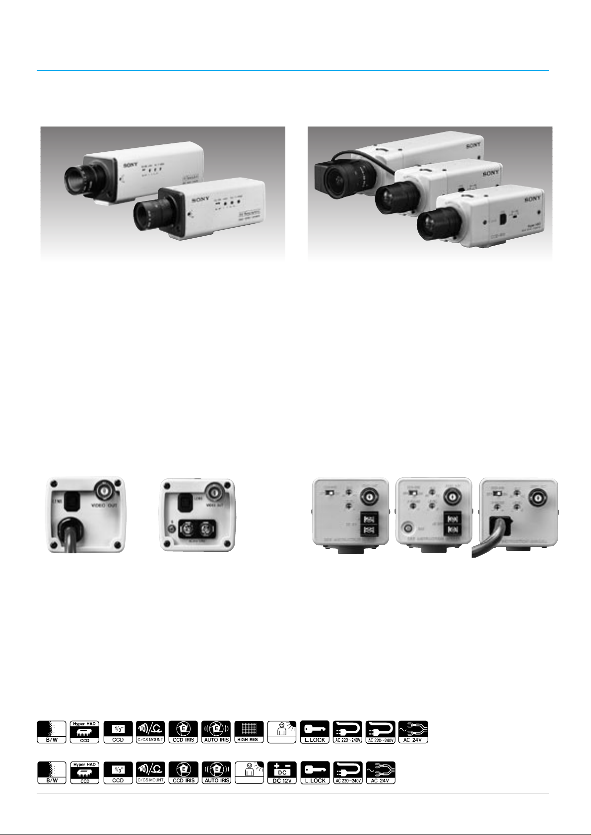
SPT -M308CE/M304CE
1/3-inch Hyper HAD CCD
High resolution
Analog backlight compensation (BLC)
AC220 to 240 V, 50Hz (SPT-M308CE)
AC 24 V, 50 Hz (SPT-M304CE)
SPT -M122CE/M124CE/M128CE
1/3-inch Hyper HAD CCD
Analog backlight compensation (BLC)
DC12 V (SPT-M122CE)
AC 24 V, 50 Hz (SPT-M124CE)
AC220 to 240 V, 50 Hz (SPT-M128CE)
SSC-M370CE
1/2-inch Hyper HAD CCD
High resolution
DC12 V or multiplexing from YS-W150P/W250P
Black & White Cameras
Quick Reference
BLACK & WHITE CAMERAS AND
MONITORS
Sony offers a comprehensive line-up of black and white cameras and monitors,
including the new 17-inch quad monitor with a sequential switcher function.
SSM-930CE
9-inch monitor
Black & White Monitors
27
SSM-125CE
12-inch monitor
SSM-175CE
17-inch monitor
SSM-Q177CE
17-inch quad monitor
Sequential switcher function
Alarm IN/OUT
Page 24
28
BLACK & WHITE VIDEO CAMERAS
CCD B/W Video Camera
SPT-M308CE/M304CE
•Especially designed for surveillance applications
•
1/3-inch IT Hyper HAD CCD offers extremely high sensitivity
with a minimum illumination of 0.25 lx at F1.2 (50 IRE)
•Outstanding horizontal resolution of 570 TV lines
•CCD IRIS function allows use of inexpensive manual iris
lenses
•AGC (Automatic Gain Control)
•Backlight compensation is possible with the LEVEL and
BLC (Back Light Control) volume controls (When using
auto iris lenses or the CCD IRIS function)
•Accepts both C/CS-mount lenses
•4-pin auto iris connector (DC driven auto-iris lens only)
•External synchronization with AC line lock
•AC power operation: AC220 to 240 V, 50 Hz
(SPT-M308CE)/AC 24 V (SPT-M304CE)
Supplied Accessories
Lens connector (1)
Lens mount cap (1)
Operation manual (1)
Supplied Accessories
Lens connector (1)
Lens mount cap (1)
Operation manual (1)
CCD B/W Video Camera
SPT-M122CE/M124CE/M128CE
•Especially designed for surveillance applications
•
1/3-inch IT Hyper HAD CCD offers extremely high sensitivity
with a minimum illumination of 0.1 lx at F1.2 (50 IRE)
•High signal-to-noise ratio of 45 dB
•CCD IRIS function allows use of inexpensive manual iris
lenses
•Backlight compensation is possible with the LEVEL and
BLC volume controls (only when using auto iris lenses
or the CCD IRIS function)
•
Accept both DC servo and VIDEO servo auto iris lenses
•Accepts both CS and C-mount lenses
•Alternative power source operation (DC 12 V for the
SPT-M122CE, AC 24 V for the SPT-M124CE, AC 220 to
240 V for the SPT-M128CE)
•External synchronization with AC line lock (for the
SPT-M124/M128CE)
•Low power consumption
SPT-M122CE SPT-M124CE
Rear Panel
Optional Accessories
VCL-4V8WEA (3.5 to 8.0 mm, F1.4)
VCL-S02WEAP (2.8 mm, F1.3)
SPT-M308CE/M304CE
Optional Accessories
VCL-4V8WEA (3.5 to 8.0 mm, F1.4)
VCL-S02WEAP (2.8 mm, F1.3)
VCL-3ADXEA (3.8 mm, F0.8)
SPT-M122CE/M124CE/M128CE
SPT-M128CESPT-M308CE SPT-M304CE
Rear Panel
SPT-M124CE
SPT-M128CE
SPT-M122CE
SPT-M308CE
SPT-M304CE
SPT-M304CESPT-M308CE
Lens shown is an option Lens shown is an option
SPT-M122CE SPT-M128CE
SPT-M124CE/
SPT-M128CE
SPT-M124CE
BLC
BLC
Page 25
29
BLACK & WHITE VIDEO CAMERAS
Supplied Accessories
Lens connector (1)
Lens mount cap (1)
Operation manual (1)
Optional Accessories
Camera adaptor YS-W150P, YS-W250P
Manual iris lens VCL-S03XM (3.6 mm, F1.6)
VCL-S06XM (6.0 mm, F1.2)
VCL-S12XM (12 mm, F1.2)
Auto iris lens VCL-S03XEA (3.6 mm, F1.6)
VCL-S06XEA (6.0 mm, F1.2)
VCL-S12XEA (12 mm, F1.2)
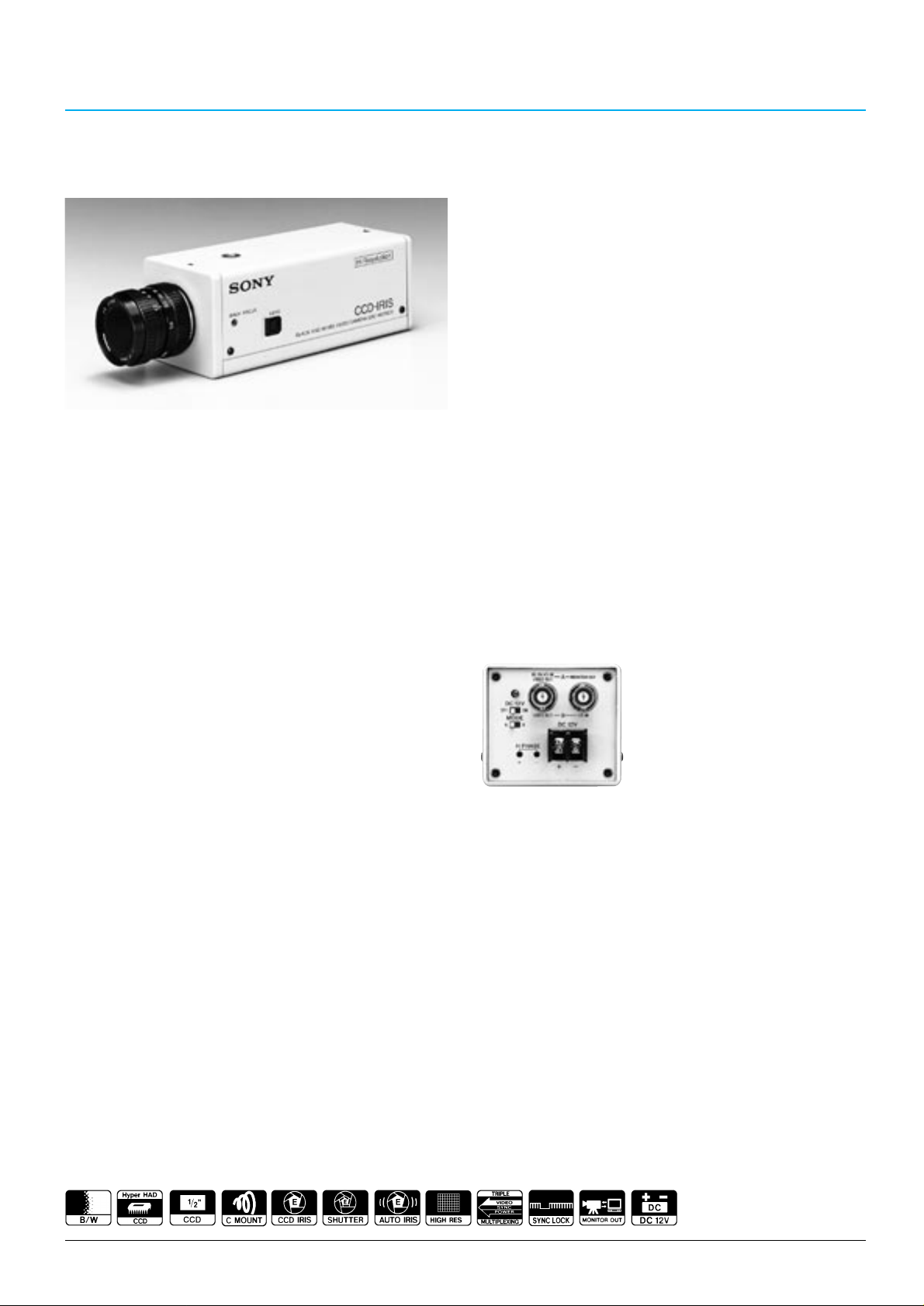
CCD B/W Video Camera
SSC-M370CE
•Especially designed for surveillance applications
•
High density 1/2-inch IT Hyper HAD CCD offers extremely
high resolution of 570 TV lines and high sensitivity with
a minimum illumination of 0.3 lx at F1.2 (50 IRE)
•Excellent signal-to-noise ratio of 50 dB
•CCD IRIS function allows use of inexpensive manual iris
lenses
•Variable speed electronic shutter
Shutter speeds — 1/50, 1/120, 1/250, 1/500, 1/1000,
1/2000, 1/4000, 1/10000 (seconds)
•Accepts C-mount lenses
•External synchronization with VS
•Single cable operation (video/sync/power triple
multiplex transmission) for easy installation with the
optional YS-W150P/W250P Camera Adaptor (Mode A)
•Monitor out function for on-the-spot camera positioning
(Mode A)
•12 V DC power supply can also be used (Mode B)
Rear Panel
Lens shown is an option
Page 26
26
BLACK & WHITE VIDEO CAMERAS
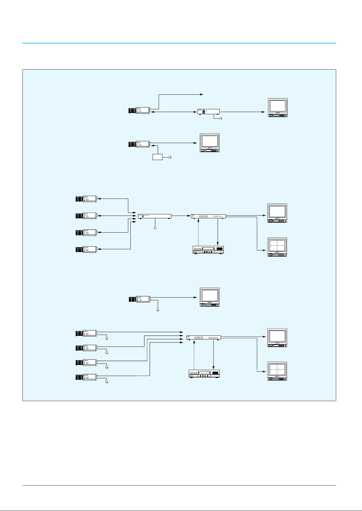
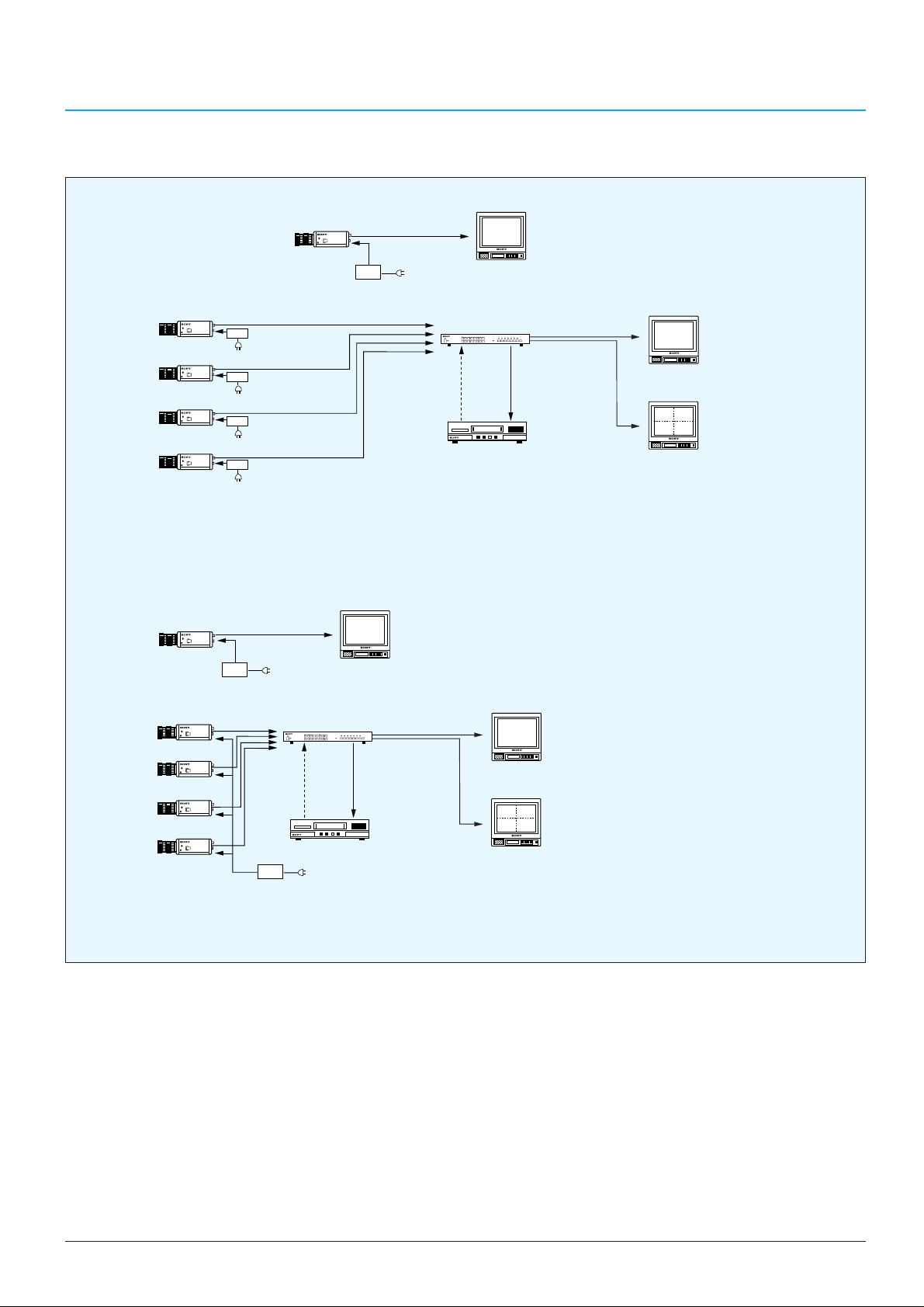
B/W Cameras Typical System
AC outlet
VIDEO OUT
(Coaxial cable)
B/W Video Monitor
EXT
TIMING IN
(Coaxial cable)
SWITCH
OUT
VIDEO
IN
Time Lapse VCR
VIDEO OUT
(Coaxial cable)
VIDEO OUT
(Coaxial cable)
VIDEO OUT
(Coaxial cable)
VIDEO OUT
(Coaxial cable)
AC outlet
AC outlet
AC outlet
AC outlet
B/W Video Monitor
B/W Video Monitor
AC outlet
DC POWER
SYNC,VIDEO
(Coaxial cable)
YS-W250P
VIDEO
OUT
(Coaxial
cable)
Muitiplexer
Muitiplexer
EXT
TIMING
IN
(Coaxial
cable)
SWITCH
OUT
VIDEO
IN
Time Lapse VCR
B/W Video Monitor
DC POWER
SYNC,VIDEO
(Coaxial cable)
DC POWER
SYNC,VIDEO
(Coaxial cable)
DC POWER
SYNC,VIDEO
(Coaxial cable)
B/W Video Monitor
AC outlet
YS-W150P
AC outlet
MONITOR OUT
(Coaxial cable)
DC POWER
SYNC,VIDEO
(Coaxial cable)
Portable Monitor
DC12 V
power supply
DC12 V
VIDEO OUT
(Coaxial cable)
VIDEO OUT
(Coaxial cable)
B/W Video Monitor
B/W Video Monitor
MONITOR OUT
(Coaxial cable)
MONITOR OUT
(Coaxial cable)
1.Single camera operation
2.Multiple camera operation
2.Multiple camera operation
(a) Mode A: Triple multiplexing operation
(b) Mode B: DC 12 V operation
SSC-M370CE
1.Single camera operation
SPT-M308CE/M128CE
Page 27
27
BLACK & WHITE VIDEO CAMERAS
MONITOR OUT
(Coaxial cable)
MONITOR OUT
(Coaxial cable)
SPT-M304CE/M124CE
2.Multiple camera operation
1.Single camera operation
SPT-M122CE
DC12 V
power supply
AC outlet
DC12 V
power supply
AC outlet
DC12 V
power supply
AC outlet
DC12 V
power supply
AC outlet
VIDEO OUT
DC12 V
power supply
VIDEO OUT
(Coaxial cable)
VIDEO OUT
(Coaxial cable)
VIDEO OUT
(Coaxial cable)
VIDEO OUT
(Coaxial cable)
B/W Video Monitor
VIDEO OUT
(Coaxial cable)
DC12 V
AC outlet
EXT
TIMING IN
(Coaxial cable)
B/W Video Monitor
Multiplexer
SWITCH
OUT
Time Lapse VCR
VIDEO
IN
B/W Video Monitor
B/W Video Monitor
AC24 V
power supply
AC outlet
EXT
TIMING IN
(Coaxial cable)
AC24 V
power supply
Multiplexer
SWITCH
OUT
Time Lapse VCR
AC outlet
VIDEO
IN
B/W Video Monitor
B/W Video Monitor
Page 28
32
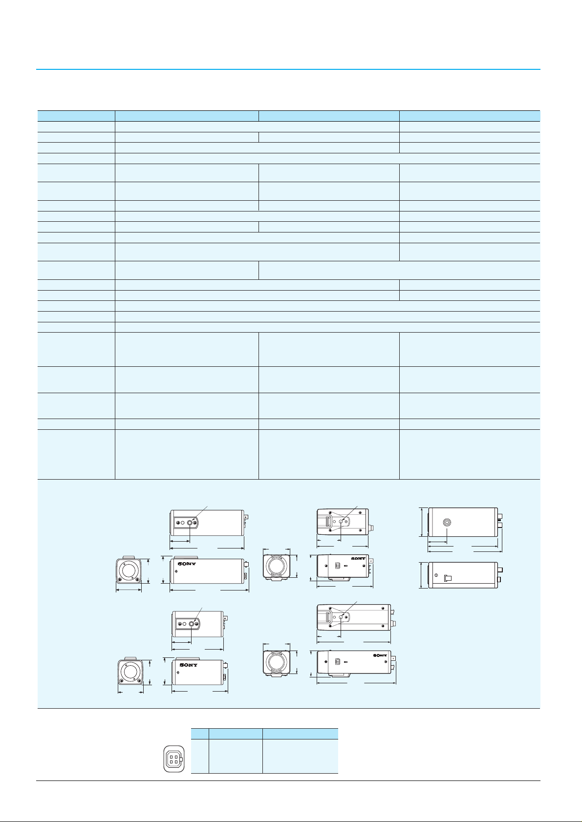
BLACK & WHITE VIDEO CAMERAS
SPT-M308CE/M304CE SPT-M122CE/M124CE/M128CE SSC-M370CE
Image device: 1/3-inch Interline Transfer Hyper HAD CCD 1/2-inch Interline Transfer Hyper HAD CCD
Picture elements: 752 (H) x 582 (V) 500 (H) x 582 (V) 752 (H) x 582 (V)
Sensing area: 4.4 x 3.3 mm 6.3 x 4.7 mm
Signal system: CCIR standard
Sync system: External with AC line lock M122CE: Internal Internal or external with VS/VBS*
M124CE/M128CE: AC line lock or MPX-VS
Phase control: V phase adjustment (±90°) M122CE: - H phase adjustment (6 positions)
M124CE/M128CE: V phase adjustment (+/-90°)
Horizontal resolution: 570 TV lines 380 TV lines 570 TV lines
Lens mount: C/CS mount adjustable C mount
Minimum illumination: AGC ON, 0.25 lx at F1.2 (50 IRE) AGC ON, 0.1 lx at F1.2 (50 IRE) AGC ON, 0.3 lx at F1.2 (50 IRE)
Automatic gain control (AGC):
Always ON ON/OFF switchable
Electronic shutter: Not applicable 1/50, 1/120, 1/250, 1/500, 1/1000,
1/2000, 1/4000, 1/10000 (seconds)
CCD IRIS control: ON/OFF switchable, ON/OFF switchable
1/50 to 1/50000 (seconds)
Backlight compensation:
Variable - user adjustable —
Signal-to-noise ratio: 45 dB (AGC ON) 50 dB (AGC OFF)
Video out: BNC, 1.0 Vp-p, 75 Ω, sync negative
Operating temperature: -10 to 50°C (14 to 122°F)
Storage temperature: -40 to 60°C (-40 to 140°F)
Power requirements: SPT-M308CE: M122CE: DC 12 V, 50 Hz 1) Multiplexing with YS-W150P/W250P
AC 220 to 240 V, 50 Hz M124CE: AC 24 V, 50 Hz 2) DC 12 V from DC 12 V power supply
SPT-M304CE: M128CE: AC 220 to 240 V
AC 24 V, 50 Hz
Power consumption: SPT-M308CE: 6.0 W M122CE: 2.4 W (0.2A) 1) 4.0 W supplied from YS-W150P/W250P
SPT-M304CE: 4.5 W M124CE: 2.5 W 2) 2.8 W at DC 12 V
M128CE: 3.5 W
Mass: SPT-M308CE: 700 g (1 lb 8 oz) M122CE: 320 g (11 oz) 660 g (1 lb 7 oz)
SPT-M304CE: 350 g (12 oz) M124CE: 320 g (11 oz)
M128CE: 750 g (1 lb 10 oz)
Auto iris type: DC servo type DC/Video servo type Video servo type
Connectors: SPT-M308CE:
VIDEO OUT (BNC), LENS (4-pin)
M122CE: DC 12 V terminals, DC 12 V terminals, LENS (4-pin)
SPT-M304CE: VIDEO OUT (BNC), VIDEO OUT (BNC), LENS (4-pin) Mode A (Triple multiplexing operation):
AC 24 V terminals, M124CE: AC 24 V terminals, GND DC IN/VS IN/VIDEO OUT (BNC),
GND,LENS (4-pin) VIDEO OUT (BNC), LENS (4-pin) MONITOR OUT (BNC)
M128CE: VIDEO OUT (BNC), LENS (4-pin) Mode B (DC 12 V operation):
VIDEO OUT (BNC), VS IN (BNC)
Dimensions:
Unit: mm (inches)
* The Burst signal is not locked
B/W Camera Specifications
Pin DC servo VIDEO servo
1 Control (-) Power (DC 9 V, 50 mA)
2 Control (+) Not connected
3 Drive (+) Video
4 Drive (-) (GND) (GND)
Lens (4-pin) Specifications
125.2 (5)
1
/4-inch–20 UNC
125.2 (5)
1
/4-inch–20 UNC
57 (2
1
/4)
57.5 (2
3
/8)
50 (2)
57 (2 1/4)
54 (2 1/4)
54 (2
1
/4)
175.2 (7)
50 (2)
57.5(2
3
/8)
165 (6 1/2)
115 (4
5
/8)
SPT-M308CE SPT-M122CE/M124CE SSC-M370CE
50 (2)
53 (2 1/8)
56 (2
1
/4)
134.5 (5 3/8)
125 (5)
39.4 (1
9
/16)
1
/4-inch–20 UNC
SPT-M304CE SPT-M128CE
50 (2)
53 (2 1/8)
/4)
1
56 (2
UNC
1
/4-inch–20
39.4 (1 9/16)
170 (6 3/4)
179.5 (7 1/8)
/8)
5
64 (2
40.5 (1 5/8)
1
/4
57 (2
155 (6 1/8)
)
164.9 (6
1
/2)
42
31
Page 29
33
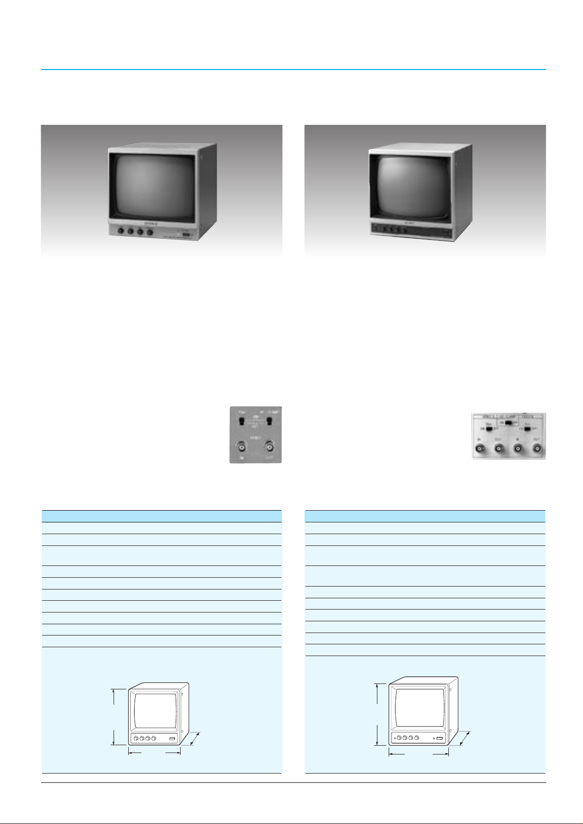
SSM-930CE
Video signal system: CCIR 625 lines, 50 fields
Picture tube: 9-inch B/W measured diagonally, 90˚ deflection
Video input: Impedance 75 Ω/high switchable
Level 0.5 to 2.0 Vp-p/75 Ω, sync negative, BNC-type
Video output:
Impedance more than 10 kΩ, loop-through, BNC-type
Horizontal resolution: More than 750 TV lines at centre
Power requirements: AC 230 V, 50/60 Hz
Power consumption: 30 W
Operating temperature: 0˚C to 35˚C (32˚F to 95˚F)
Storage temperature: -10˚C to 40˚C (14˚F to 104˚F)
Mass: 5.8 kg (13 lb)
Dimensions:
Unit: mm (inches)
SSM-125CE
Video signal system: CCIR 625 lines, 50 fields
Picture tube: 12-inch B/W measured diagonally, 90˚ deflection
Video input: Impedance 75 Ω/high switchable
Level 0.5 to 2.0 Vp-p/75 Ω, sync negative, BNC-type (x 2)
Video output: Impedance more than 10 kΩ, loop-through,
BNC-type (x 2)
Horizontal resolution: More than 750 TV lines at centre
Power requirements: AC 230 V, 50/60 Hz
Power consumption: 30 W
Operating temperature: 0˚C to 35˚C (32˚F to 95˚F)
Storage temperature: -10˚C to 40˚C (14˚F to 104˚F)
Mass: 9.2 kg (20 lb 5 oz)
Dimensions:
Unit: mm (inches)
BLACK & WHITE VIDEO MONITORS
B/W Monitor
SSM-930CE
B/W Monitor
SSM-125CE
•CCIR standard
•9-inch CRT size
•Excellent picture quality with more than 750 TV lines
horizontal resolution
•Loop-through video input, with switchable 75 Ω
termination
•DC clamp switch provides a stable reference for the
black level
•19-inch EIA standard rack mountable for dual monitor
configuration
•Front controls: Power, H-hold, V-hold, contrast and
brightness
•High immunity to external electrical
and magnetic interference
•Suitable for many monitoring applications
•CCIR standard
•12-inch CRT size
•Excellent picture quality with more than 750 TV lines
horizontal resolution
•
Dual loop-through video inputs, with switchable 75
Ω
termination
•DC clamp switch provides a stable reference for the
black level
•Front controls: Power, INPUT select, H-hold, V-hold,
contrast and brightness
•High immunity to external electrical and magnetic
interference
•Suitable for many monitoring
applications
Specifications Specifications
Rear Panel
Rear Panel
)
8
/
5
219 (8
220 (8 3/4)
254 (10)
303 (12)
296 (11 3/4)
7
301 (11
)
8
/
Page 30
34
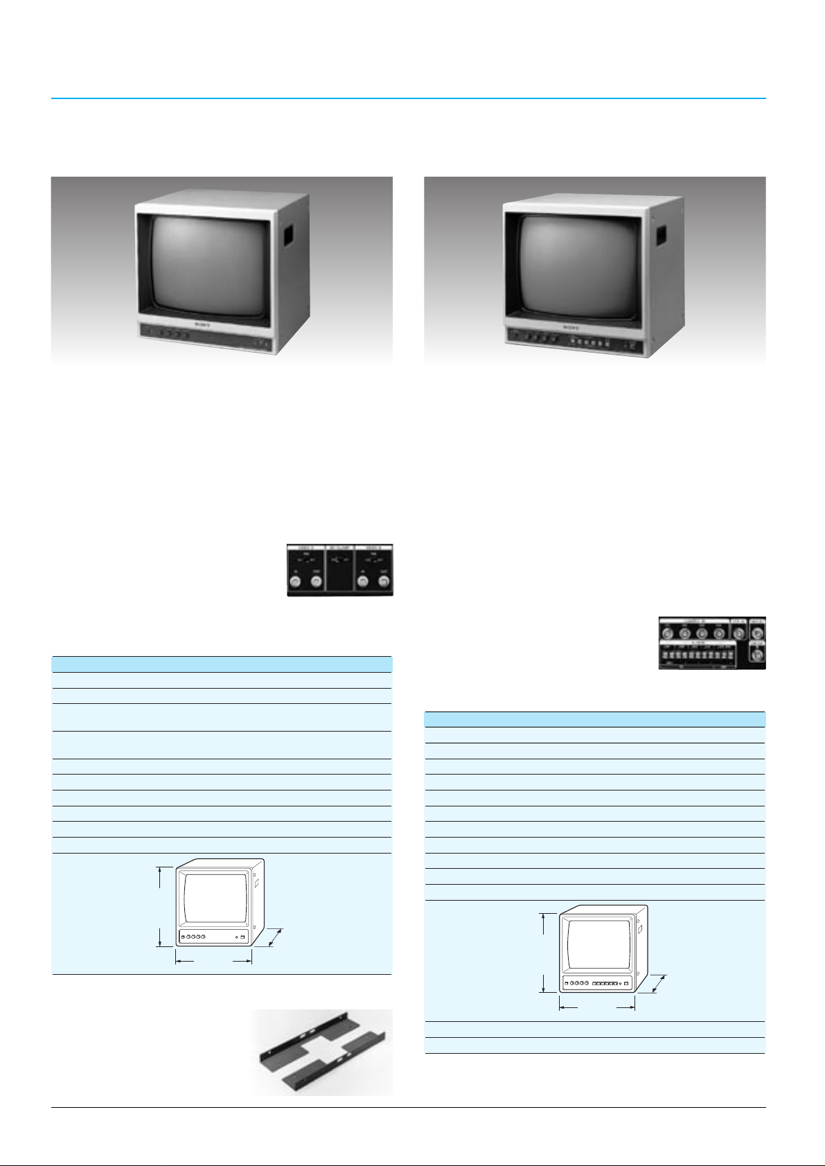
BLACK & WHITE VIDEO MONITORS
B/W Monitor
SSM-175CE
•CCIR standard
•17-inch CRT size
•Excellent picture quality with more than 850 TV lines
horizontal resolution
•Dual loop-through video inputs, with switchable 75 Ω
termination
•DC clamp switch which provides a stable black level
reference
•Front controls: Power, INPUT select, H-hold, V-hold,
contrast and brightness
•19-inch EIA standard rack mountable
•High immunity to external electrical
and magnetic interference
•Suitable for many monitoring
applications
SSM-175CE
Video signal system: CCIR 625 lines, 50 fields
Picture tube: 17-inch B/W measured diagonally, 90˚ deflection
Video input: Impedance 75 Ω/high switchable
Level 0.5 to 2.0 Vp-p/75 Ω, sync negative, BNC-type (x 2)
Video output: Impedance more than 10 kΩ, loop-through,
BNC-type (x 2)
Horizontal resolution: More than 850 TV lines at centre
Power requirements: AC 220 V to 240 V, 50/60 Hz
Power consumption: 37 W
Operating temperature: 0˚C to 35˚C (32˚F to 95˚F)
Storage temperature: -10˚C to 40˚C (14˚F to 104˚F)
Mass: 17.5 kg (38 lb 9 oz)
Dimensions:
Unit: mm (inches)
Specifications
SSM-Q177CE
Video signal system: CCIR standard
Picture tube:
17-inch CRT, measured diagonally, 90° deflection
Resolution: More than 850 lines (full screen)
Camera input/VCR input: Composite: 1.0 Vp-p, sync negative, 75 Ω
Video output/VCR output: Composite: 1.0 Vp-p, sync negative, 75 Ω
Power requirements: AC 230 V, 50/60 Hz
Power consumption: Approx. 45 W
Operating temperature: 0 to 35°C (32 to 95°F)
Storage temperature: -10 to 40°C (14 to 104°F)
Operating humidity: 0 to 90% (no condensation)
Storage humidity: 0 to 90% (no condensation)
Dimensions:
Unit: mm (inches)
Mass: 18.8 kg (41 lb 6 oz)
Regulation compliance: EN 60 065 (TÜV), CE (EMC, LVD), C-Tick Mark
Specifications
Rear Panel
SSM-175CE/Q177CE Optional Accessory
Rack Mounting Bracket
RMM-171
B/W Quad Monitor
SSM-Q177CE
•CCIR standard
•Quad Screen Display permits up to four compressed,
split pictures to be displayed simultaneously and
recorded on a single VCR
•High quality compressed images with 8-bit signal
processing for clearer pictures
•Sequential Switcher Function provides automatic
switching between up to four cameras, with a
selectable dwell time; SKIP channel also selectable
•Newly developed flyback transformer provides the high
voltage stability required to minimise picture zooming
•Freeze Picture Function can freeze each picture in
quad mode, as well as freeze a VCR playback picture
•Alarm IN/OUT with audible alarm and flashing LED
•Video Loss Detection with on-screen notification
•On-screen menus display Date,
Time and Camera ID
•19-inch EIA standard rack
mountable
Rear Panel
)
8
/
1
409 (16
424 (16 3/4)
380 (15)
)
8
/
1
409 (16
424 (16 3/4)
380 (15)
Page 31
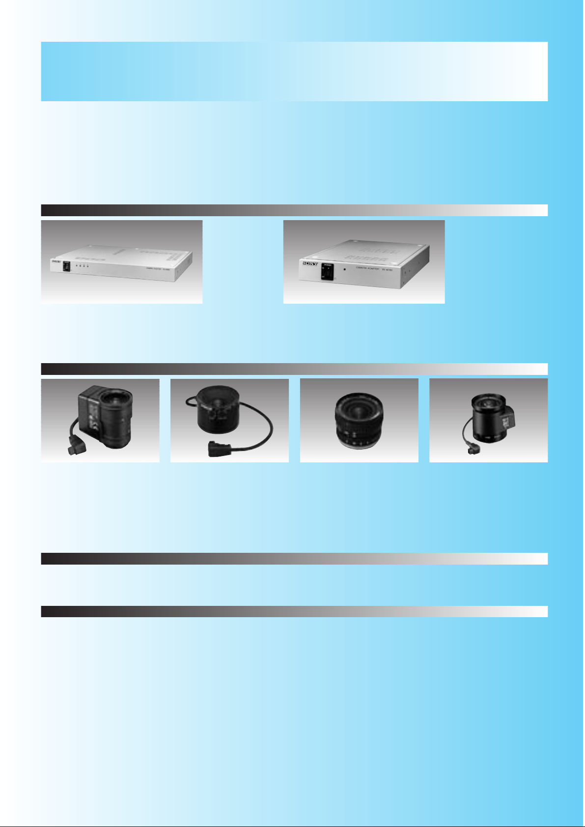
35
YS-W250P
Transmit DC power/video/sync to
SSC-DC50AP/DC10AP/C370P/M370CE
Up to four cameras can be connected
YS-W150P
Transmits DC power/Video/Sync to
SSC-DC50AP/DC10AP/C370P/M370CE
Camera Adaptors
Quick Reference
CAMERA OPTIONAL ACCESSORIES
RG-59B/U, RG-6A/U, RG11A/U
Auto Iris type for 1/3 inch
CS-mount camera
VCL-4V8WEA
VCL-S02WEAP
Auto Iris type for 1/2 inch
CS-mount camera
VCL-S03XEA
VCL-S06XEA
VCL-S12XEA
Manual Iris type for 1/2 inch
CS-mount camera
VCL-S03XM
VCL-S06XM
VCL-S12XM
Lenses
Coaxial Cables
YT-B21, T-301/305/307
Mounting brackets
Aspherical auto iris type for 1/2-inch
CS-mount cameras
VCL-3ADXEA
Page 32
36
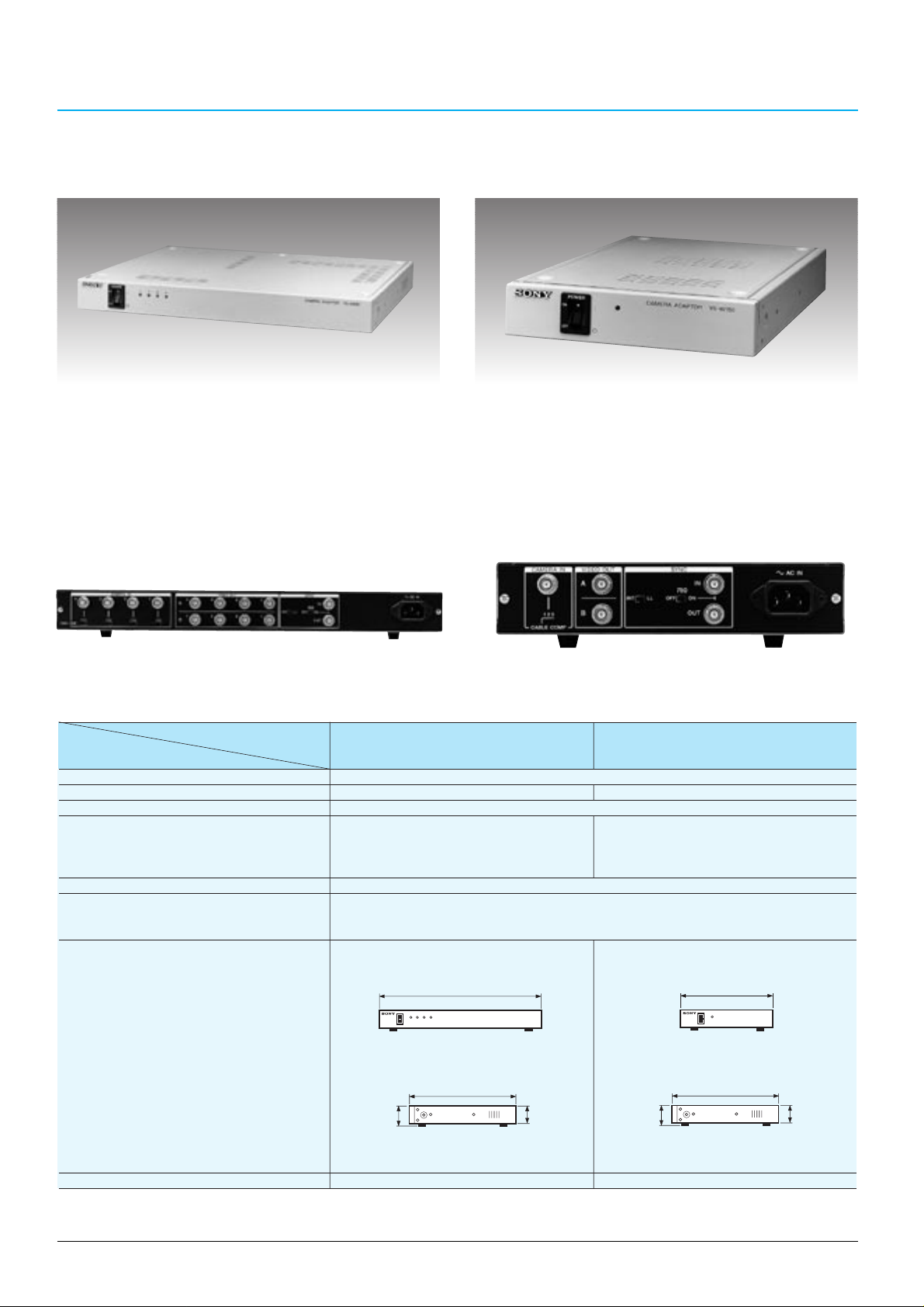
CAMERA ADAPTORS
Camera Adaptor
YS-W250P
Camera Adaptor
YS-W150P
Rear PanelRear Panel
for SSC-DC50AP/DC10P/
C370P/M370CE
for SSC-DC50AP/DC10P/C370P/
M370CE
•Transmits DC power and video/sync signal between the
adaptor and the camera over a single coaxial cable
•Internal or external synchronization with VS or AC line
lock
•Maximum cable length: 600 m with RG-11A/U (7C-2V)
coaxial cable
•Transmits DC power and video/sync signal between the
adaptor and the camera over a single coaxial cable
•Up to four cameras can be connected
•Internal or external synchronization with VS or AC line
lock
•Maximum cable length:
SSC series cameras – 600 m with RG-11A/U (7C-2V)
coaxial cable
Specifications
Models
YS-W250P YS-W150P
Specifications
Power requirements AC 220 to 240 V, 50 Hz
Power consumption 48 W 15 W
Operating temperature -10˚C to 50˚C (14˚F to 122˚F)
Connectors CAMERA IN 1 to 4 (BNC x 4) CAMERA IN (BNC)
VIDEO OUT A: 1 to 4 (BNC x 4) VIDEO OUT (BNC x 2)
VIDEO OUT B: 1 to 4 (BNC x 4) SYNC IN/OUT (BNC,
SYNC IN/OUT (BNC, loop-through,75 Ω ON/OFF) loop-through,75 Ω ON/OFF)
DC out —
Maximum cable length 300 m using RG-59B/U (3C-2V)
500 m using RG-6A/U (5C-2V)
600 m using RG-11A/U (7C-2V)
Dimensions
Mass 3.6 kg (7 lb 15 oz) 1.9 kg (4 lb 3 oz)
Unit: mm (inches)
424 (163/4)
330 (13)
44 (1
3
/
4
)
52 (2
1
/
8
)
330 (13)
212 (83/8)
44 (1
3
/
4
)
52 (2
1
/
8
)
Page 33
37
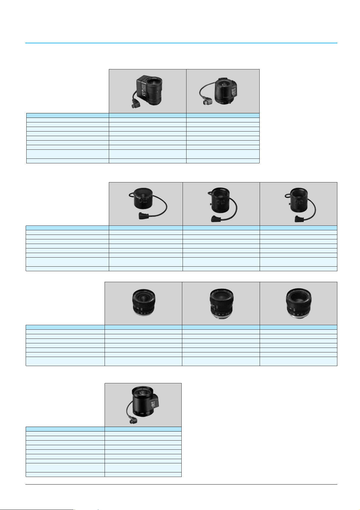
LENSES
Models VCL-4V8WEA VCL-S02WEAP
Mount CS CS
Focal length 3.5 to 8.0 mm 2.8 mm
Iris control Auto Auto
Maximum aperture ratio 1 : 1.4 1 : 1.3
Minimum object distance 0.3 m 0.2 m
Filter size ––– M30.5 x 0.5 mm
Mass 72 g (3 oz) 41 g (1.4 oz)
Dimensions ø35.0 x 54.0 x 46.0 mm ø32.0 x 39.8 x 33.0 mm
(dia. x H x L) (1 7/16 x 2 1/4 x 1 13/16 inches) (1 5/16 x 1 5/8 x 1 5/16 inches)
Cable length 100 mm (4 inches) 310 mm (12 1/4 inch)
1) Auto Iris Type
(DC/VIDEO servo type/Non-EE
amplifier type/Non-ALC type)
Lenses for 1/3-inch CS-mount cameras
Lenses for 1/2-inch C-mount cameras
1) Auto Iris Type
(Video servo type/EE amplifier
type/ALC type)
Models VCL-S03XEA VCL-S06XEA VCL-S12XEA
Mount C C C
Focal length 3.6 mm 6.0 mm 12 mm
Iris control Auto Auto Auto
Maximum aperture ratio 1 : 1.6 1 : 1.2 1 : 1.2
Filter size ––– M43 x 0.75 mm M43 x 0.75 mm
Mass 88 g (3.1 oz) 128 g (4.5 oz) 126 g (4.4 oz)
Dimensions ø45 (dia.) x 32.9 (L) mm ø45.5 (dia.) x 48.5 (L) mm ø45.5 (dia.) x 48.5 (L) mm
(1 13/16 x 1 5/16 inches) (1 13/16 x 1 15/16 inches) (1 13/16 x 1 15/16 inches)
Supply voltage DC 8 - 16 V DC 8 - 16 V DC 8 - 16 V
2) Manual Iris Type
Models VCL-S03XM VCL-S06XM VCL-S12XM
Mount C C C
Focal length 3.6 mm 6.0 mm 12 mm
Iris control Manual Manual Manual
Maximum aperture ratio 1 : 1.6 1 : 1.2 1 : 1.2
Filter size M35.5 x 0.5 mm M35.5 x 0.5 mm M35.5 x 0.5 mm
Mass 66 g (2.3 oz) 74 g (2.6 oz) 60 g (2.1 oz)
Dimensions ø38 (dia.) x 28.6 (L) mm ø38 (dia.) x 36.4 (L) mm ø38 (dia.) x 30.8 (L) mm
(1 1/2 x 1 3/16 inches) (1 1/2 x 1 7/16 inches) (1 1/2 x 1 1/4 inches)
Model VCL-3ADXEA
Mount CS
Focal length 3.8 mm
Iris control Auto
Maximum aperture ratio 1 : 0.8
Minimum object distance 0.15 m
Filter size M43 ´ 0.75 mm
Mass 150 g (5.3 oz)
Dimensions ø45.0 x 56.8 x 52.5 mm
(dia. x H x L) (1 13/16 x 2 1/4 x 2 1/8 inches)
Cable length 90 mm (3 5/8 inch)
Aspherical auto iris lens for 1/2-inch CS-mount cameras
(DC servo type/Non-EE amplifier
type/Non-ALC type)
Page 34
38
Cable
Mass Cable loss (dB)
(100 m)
(dB/100 m, at 4 MHz) (dB/100 m, at 200 MHz)
RG-59B/U (3C-2V) 5 kg 2.6 19.6
RG-6A/U (5C-2V) 8 kg 1.8 12.5
RG-11A/U (7C-2V) 14 kg 1.3 10.5
Coaxial Cables (by Fujikura)
CABLES
MOUNTING BRACKETS
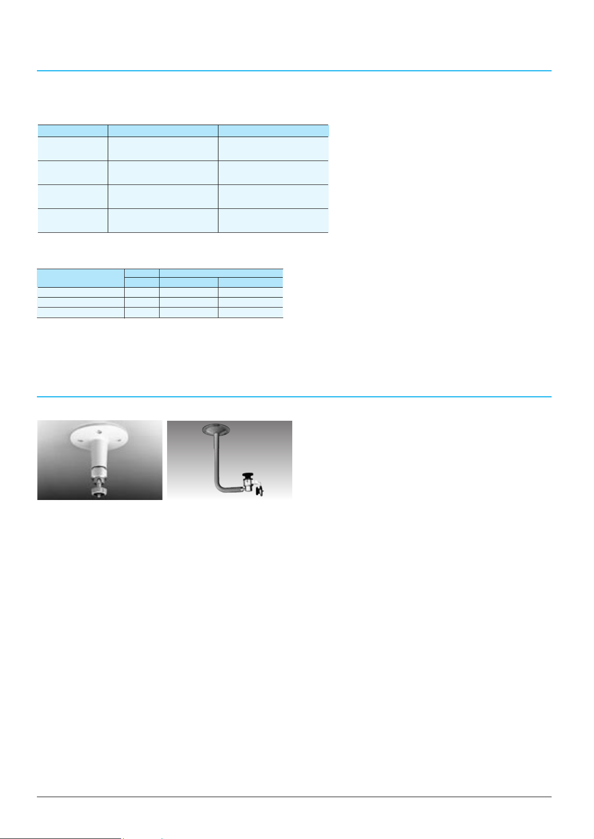
Mounting Bracket
YT-B21
•For indoor use
Maximum load: 2 Kg
Length: 136.6 mm
Mass: 200 g
Mounting Bracket
T-301/305/307
•T-301- suitable for mounting housed or unhoused cameras
•T-305/307- only accept unhoused cameras for installation
Maximum load: 10Kg
Length: T-301: 260 mm+150 mm
T-305: Min.275 mm/Max.405 mm
T-307: 160 mm
Mass: T-301/305: 0.7 Kg
T-307: 0.6 Kg
T-301
CAMERA/CAMERA ADAPTOR/CONNECTING CABLE COMBINATION CHART
YS-W250P YS-W150P
SSC-DC50AP YES YES
(Coaxial cable) (Coaxial cable)
SSC-DC10P YES YES
(Coaxial cable) (Coaxial cable)
SSC-C370P YES YES
(Coaxial cable) (Coaxial cable)
SSC-M370CE YES YES
(Coaxial cable) (Coaxial cable)
Page 35
39
YS-DX316P/DX216CE
16 channel colour duplex multiplexer (YS-DX316P)
16 channel B&W duplex multiplexer (YS-DX216CE)
YS-SX310P/SX210CE
10 channel colour simplex multiplexer (YS-SX310P)
10 channel B&W simplex multiplexer (YS-SX210CE)
Multiplexers
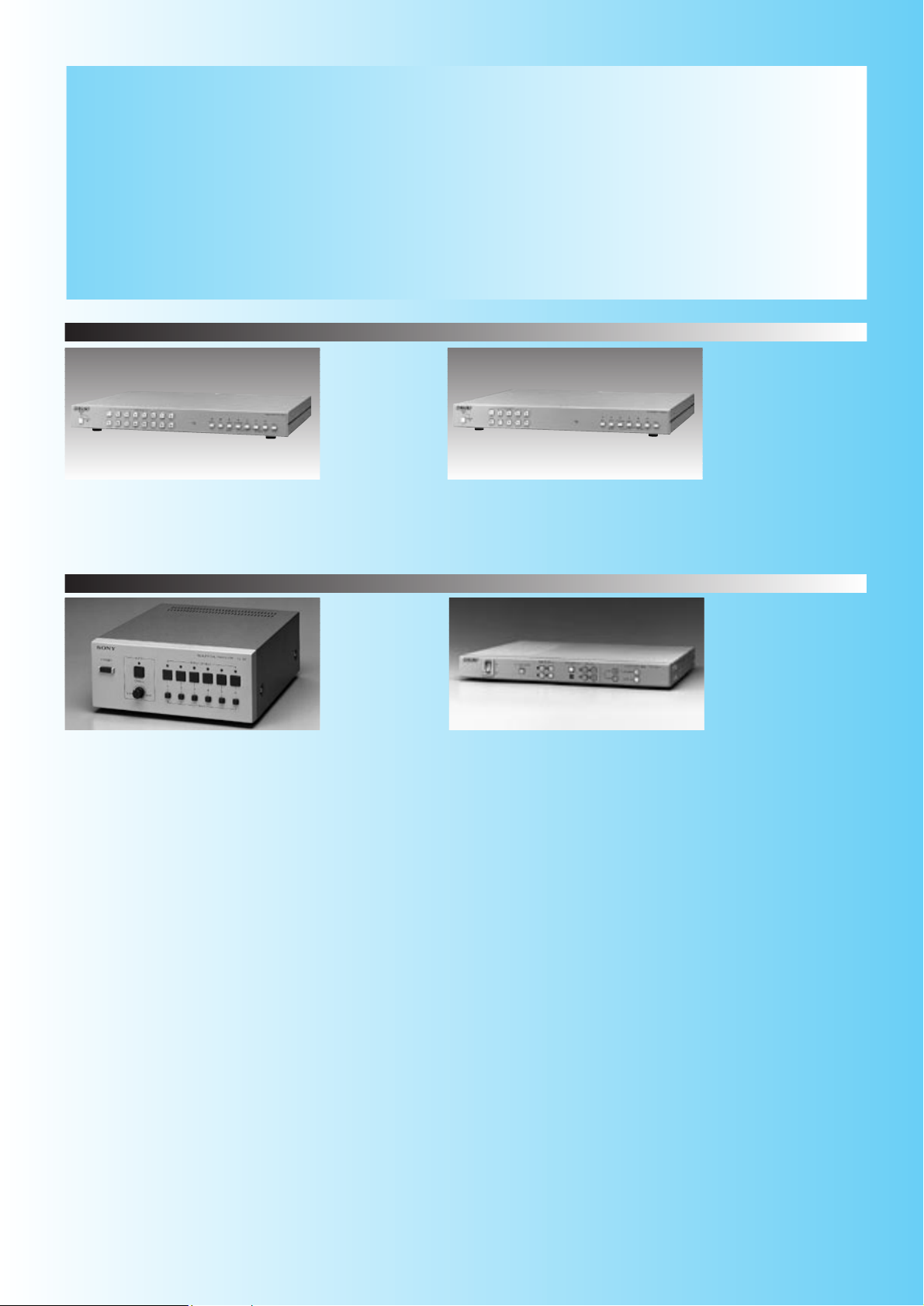
Quick Reference
MULTIPLEXERS AND SWITCHERS
Sony multiplexers and switchers facilitate efficient control in multiple camera monitoring
systems. Four different multiplexers, two duplex and two simplex, allow up to 16 and 10
channels respectively to be displayed on a single monitor. These multiplexers also
provide sequential switching, picture zoom and freeze, and powerful alarm functions.
The line-up of switchers includes a versatile quad switcher and a 6-channel sequential
switcher.
YS-Q440P
Quad switcher
Switchers
YS-S6
6-channel sequential switcher
Page 36
40
MUL TIPLEXERS
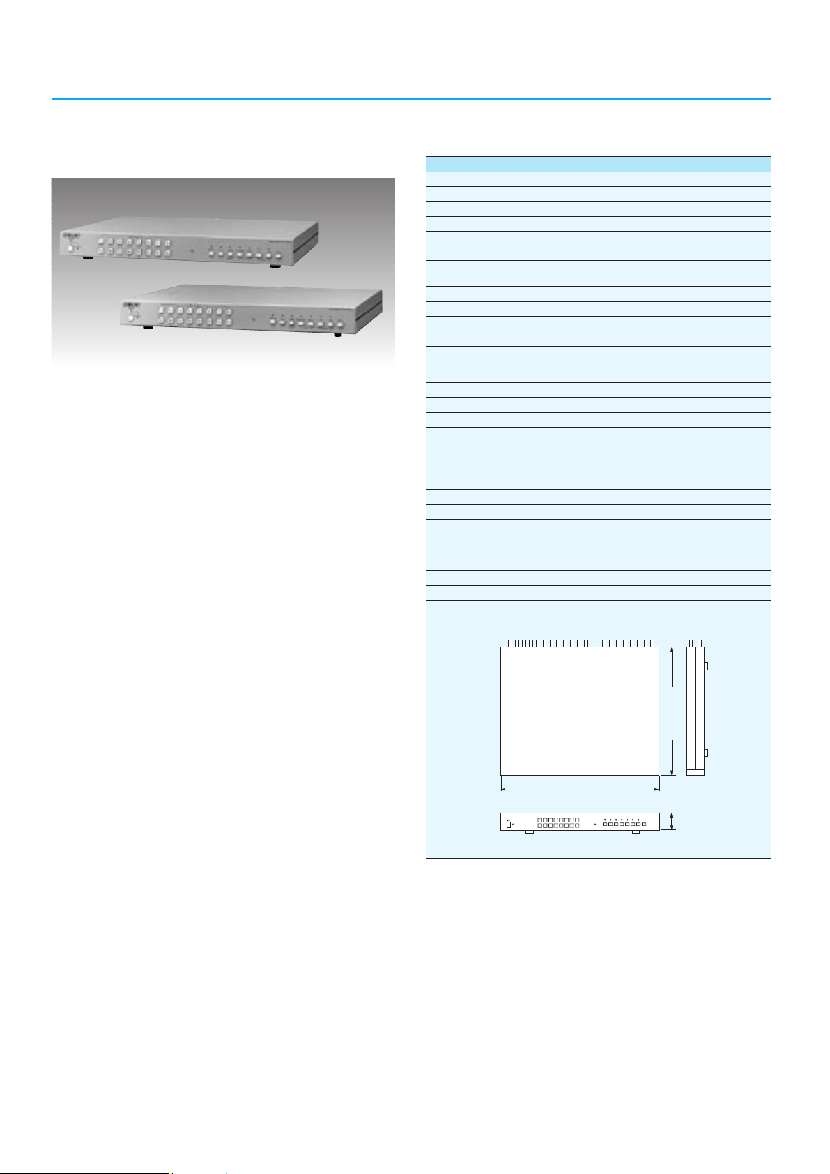
•Full duplex video multiplexer with up to 16 camera inputs
•Either asynchronous or synchronous cameras can be
connected
•Multiplex recording to one VCR while switching between
each camera by a field (1/50 sec.) for precise surveillance
of multiple points
•Long time recording with Time Lapse VCR
•Video loop through for up to 16 cameras
• Live pictures can be displayed in full screen, sequence,
quad, multi-screen (7/10/13/16) while simultaneously
recording
•Auto sequential switching in quad mode in addition to full
screen sequence switching
•Recorded images can be played back in the bottom right
screen of the 13 or 16-picture display simultaneously with
live images
•Playback can be reviewed in full screen, sequence, quad,
and multi-screen (7/10/13/16)
•Live images can be displayed in the bottom right screen of
the 13 or 16-picture display simultaneously with
recorded images
•MONITOR 2 can be used for spot monitoring
•Freeze picture function in both live and playback mode
•Electronic zoom (x2) function in both live and play back
mode
•An S-VHS VCR can be connected via the S-video
output/input connector (YS-DX316P only)
•Built in time/date and camera title generator
•Easy on screen setup
•16 alarm inputs, each corresponding to a camera input
•Programmable freeze, zoom and buzzer functions in
16-picture split mode for alarm inputs
•Alarm monitor function automatically provides independent
monitoring of channels in which alarms occur on
MONITOR 2
•Programmable alarm recording time mode
•Alarm memory function can store up to 100 alarm events
(camera number, date and time)
•Video loss detection function
•Remote control capability via a D-sub 25-pin
•Compact 1U height unit and rack mount capability
YS-DX316P YS-DX216CE
General
Video signal system: PAL standard CCIR standard
Power requirements: AC 220 to 240 V, 50 Hz
Power consumption: 22 W 16 W
Operating temperature: 0 to 45˚C (32 to 113˚F)
Storage temperature: -20 to 60˚C (-4 to 140˚F)
Dimensions: 420 (W) x 54 (H) x 320 (D) mm
(16 5/8 x 2 1/4 x 12 5/8 inches)
Mass: Approx. 4.2 kg (9 lb 4 oz)
Video inputs
Camera input 1 to 16: BNC type, VS or VBS, 1.0 Vp-p, 75 Ω
VCR input: BNC type, VS or VBS, 1.0 Vp-p, 75 Ω
S-VHS Y/C inputs: Din Connector -
Y: 1.0 Vp-p, 75 Ω
C: 0.286 Vp-p, 75 Ω
Video outputs
Monitor 1 output: BNC type x 1, VS or VBS BNC type x 1, VS
Monitor 2 output: BNC type x 1, VS or VBS BNC type x 1, VS
VCR output: BNC type, VS or VBS, BNC type, VS,
1.0 Vp-p, 75 Ω 1.0 Vp-p, 75 Ω
S-VHS Y/C output: Din Connector -
Y: 1.0 Vp-p, 75 Ω
C: 0.286 Vp-p, 75 Ω
Alarm output: DC 5 V 5.7 kΩ
Alarm duration: 10, 20, 30, 40, 50, 60, CC* sec.
Switch input from VCR: Low active (100 kΩ pull-up)
Control terminal: D-sub: 25-pin
Alarm input: contact close (x 16)
Remote control input
Sequence time: 0.5 to 30 sec. (0.5 sec. increments)
On-screen display: 8 character title, date/time
Buzzer: ON/OFF
Dimensions:
Unit: mm (inches)
Specifications
Supplied Accessories
Rack mount kit (for EIA standard rack) (1 set)
D-sub 25-pin plug components (1 set)
Operation manual (1)
* Stays in alarm mode for as long as alarm input remains active
Multiplexer
YS-DX316P/YS-DX216CE
)
8
/
5
320 (12
420 (16 5/8)
)
4
/
1
54
(2
Page 37
41
MUL TIPLEXERS
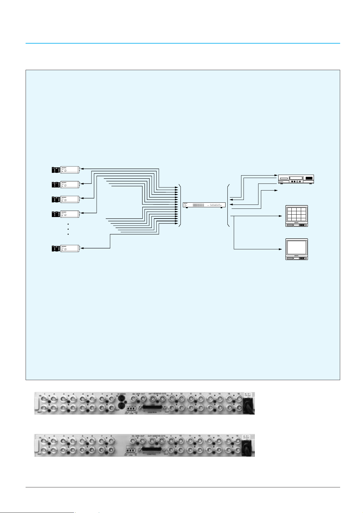
YS-DX316P/DX216CE Typical System
YS-DX316P
YS-DX216CE
Rear Panel
Video Camera 1
Video Camera 16
VIDEO OUT
(coaxial cable)
VIDEO OUT
(coaxial cable)
VIDEO INPUT
1to16
YS-DX316P/DX216CE
REC
OUT
VIDEO OUT
VIDEO IN
PB IN
ALARM OUT
MON OUT 1
MON OUT 2
SW OUT
ALARM
IN
Time Lapse VCR
(ex. SVT-L230P)
Colour Video Monitor
(ex. SSM-20N5E)
Colour Video Monitor
(ex. SSM-20N5E)
Page 38
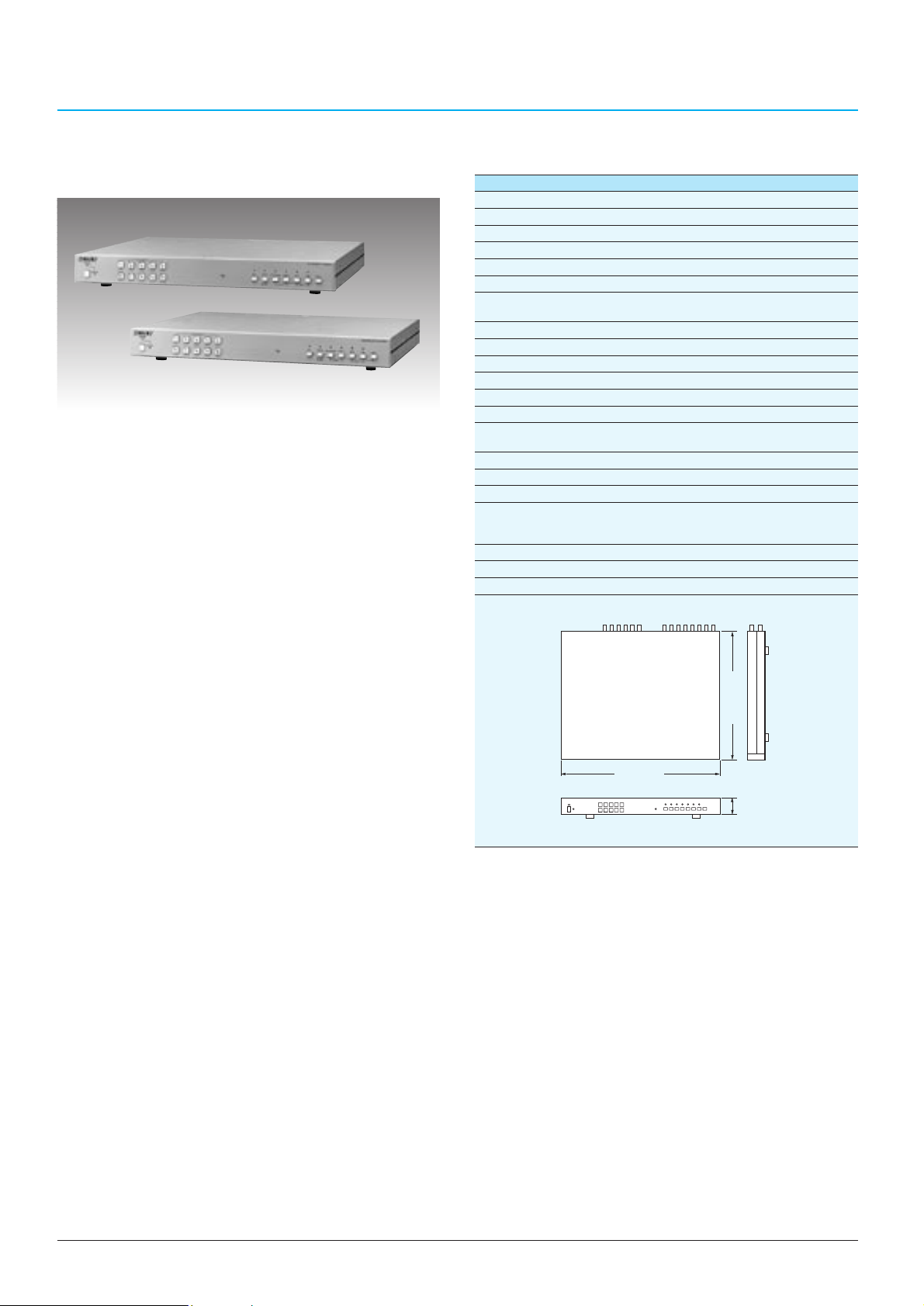
42
MUL TIPLEXERS
Multiplexer
YS-SX310P/YS-SX210CE
•Simplex video multiplexer with up to 10 camera inputs
•Either asynchronous or synchronous cameras can be
connected
•Multiplex recording to one VCR while switching
between each camera by a field (1/50 sec.) for precise
surveillance of multiple points
•Long time recording with Time Lapse VCR
•Video loop through for up to 10 cameras
•Live pictures can be displayed in full screen or
sequence while simultaneously recording
•Quad or multi-screen (7/10) can be displayed*
•Playback can be reviewed in full screen, sequence,
quad, and multi-screen (7/10)
•Freeze picture function in play back mode
•Electronic zoom (x2) function in play back mode
•Built in time/date and camera title generator
•Easy on screen setup
•10 alarm inputs, each corresponding to a camera input
•Alarm monitor function automatically provides
independent monitoring of channels on which alarms
occur
•Programmable alarm recording time mode
•Alarm memory function can store up to 100 alarm
events (camera number, date and time)
•Video loss detection function
•Remote control capability via a D-sub 25-pin
•Compact 1U height unit and rack mount capability
* This feature is not applicable when unit recording with a VTR
YS-SX310P YS-SX210CE
General
Video signal system: PAL standard CCIR standard
Power requirements: AC 220 to 240 V, 50 Hz
Power consumption: 14 W 12 W
Operating temperature: 0 to 45˚C (32 to 113˚F)
Storage temperature: -20 to 60˚C (-4 to 140˚F)
Dimensions: 420 (W) x 54 (H) x 320 (D) mm
(16 5/8 x 2 1/4 x 12 5/8 inches)
Mass: Approx. 4.2 kg (9 lb 4 oz)
Video inputs
Camera input 1 to 10: BNC type, VS or VBS, 1.0 Vp-p, 75 Ω
VCR input: BNC type, VS or VBS, 1.0 Vp-p, 75 Ω
Video outputs
Monitor output: BNC type x 1, VS or VBS BNC type x 1, VS
VCR output: BNC type, VS or VBS, BNC type,
1.0 Vp-p, 75 Ω VS, 1.0 Vp-p, 75 Ω
Alarm output: DC 5 V 5.7 kΩ
Alarm duration: 10, 20, 30, 40, 50, 60, CC* sec.
Switch input from VCR: Low active (100 kΩ pull-up)
Control terminal: D-sub: 25-pin
Alarm input: contact close (x 10)
Remote control input
Sequence time: 0.5 to 30 sec. (0.5 sec. increments)
On-screen display: 8 character title, date/time
Buzzer: ON/OFF
Dimensions:
Unit: mm (inches)
Specifications
Supplied Accessories
Rack mount kit (for EIA standard rack) (1 set)
D-sub 25-pin plug components (1 set)
Operation manual (1)
* Stays in alarm mode for as long as alarm input remains active
)
8
/
5
320 (12
420 (16 5/8)
)
4
/
1
54
(2
Page 39
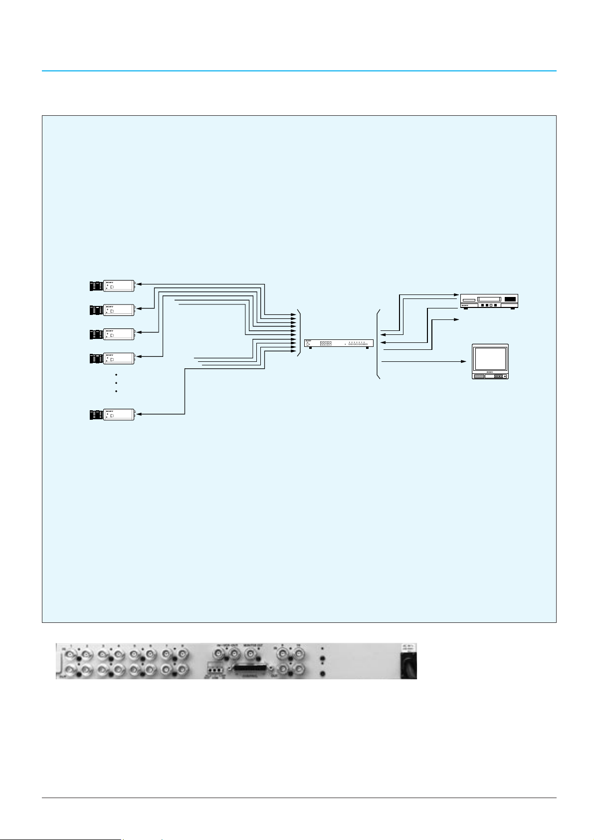
43
MUL TIPLEXERS
YS-SX310P/SX210CE Typical System
YS-SX310P/SX210CE
Rear Panel
Video Camera 1
Video Camera 10
VIDEO OUT
(coaxial cable)
VIDEO OUT
(coaxial cable)
VIDEO INPUT
1to10
YS-SX310P/SX210CE
REC
OUT
VIDEO OUT
VIDEO IN
PB IN
ALARM OUT
MON OUT
SW OUT
ALARM
IN
Time Lapse VCR
(ex. SVT-L230P)
Colour Video Monitor
(ex. SSM-20N5E)
Page 40
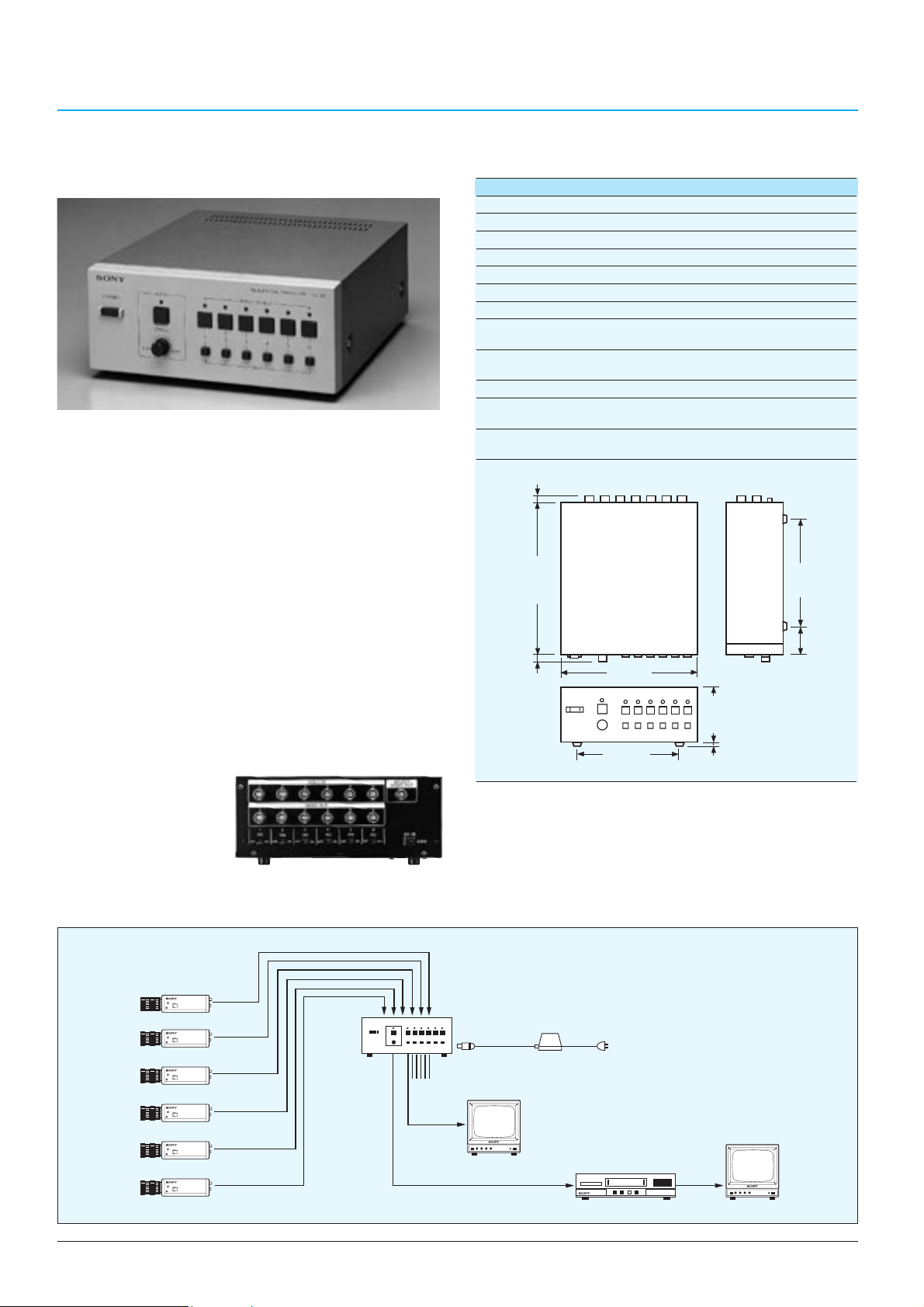
44
SWITCHERS
YS-S6
General
Power requirements: DC 9 V
Power consumption: Approx. 2.3 W
Operating temperature: 0˚C to 40˚C (32˚F to 104˚F)
Storage temperature: -20˚C to 60˚C (-4˚F to 140˚F)
Mass: Approx. 2.1 kg (4 lb 10 oz)
Input signals
VIDEO INPUT 1 to 6: BNC type, 1.0 Vp-p, 75 Ω, unbalanced,
sync negative
DC IN: DC jack type
DC 9 V (DC 7 V to 15 V is allowed)
Output signals
VIDEO OUTPUT 1 to 6: BNC type, loop-through output of VIDEO
INPUT, 75 Ω termination ON/OFF switchable
SELECT VIDEO OUT: BNC type, 1.0 Vp-p, 75 Ω, unbalanced,
sync negative
Dimensions:
Unit: mm (inches)
NOTE: AC Adaptor is an option.
Specifications
6-channel Sequential Switcher
YS-S6
•Compact-size sequential switcher for small surveillance
systems
•Six VIDEO INPUTs with loop-through capability
•
The pictures from up to six video cameras can be monitored
sequentially on a monitor via the SELECT VIDEO OUT
•The use of DWELL dial enables various dwell time
(displayed time) settings per each monitor from 1
second to 30 seconds
•Both Auto/Manual switching modes are available
Auto: Pressing the AUTO button provides automatic
sequential monitoring of all camera inputs
Manual:The INPUT SELECT buttons allow users
manually select a specific camera input and
view it continuously
•Pictures from connected camera which don’t have to
be monitored can be skipped by the use of SKIP
buttons 1 through 6
•Accepts also NTSC/EIA signal
Supplied Accessory
Operation manual (1)
Rear Panel
YS-S6 Typical System
/32)
13
10 (
/4)
3
246 (9
/8)
3
9.5 (
220 (8 3/4)
/2)
1
88 (3
)
/32
162 (6 1/2)
11
8 (
175 (7)
/16)
15
49 (1
Video Camera 1
Video Camera 2
Video Camera 3
Video Camera 4
Video Camera 5
Video Camera 6
YS-S6
SELECT
VIDEO OUT
VIDEO OUT 1 to 6
Video IN
1 to 6
DC INPUT
Video Monitor
AC Adaptor
Video Monitor
Time Lapse VCR
Page 41
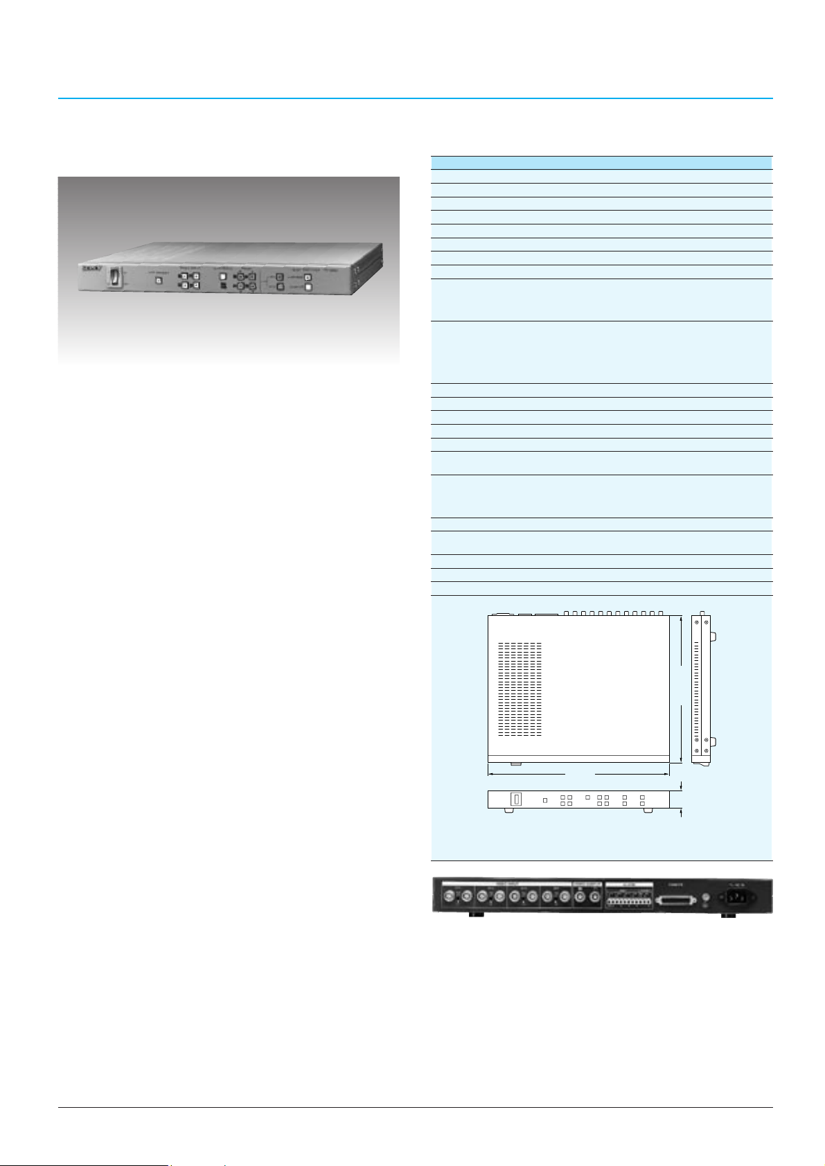
45
SWITCHERS
Quad Switcher
YS-Q440P
•High performance Quad Image Splitter with an auto
sequential switcher
•Up to four compressed, split pictures can be
simultaneously displayed on a single monitor and
recorded on a single VCR
•Automatic switching between up to four cameras can
also be performed on a monitor and the switching
interval can be selected in one-second increments from
1 to 30 seconds
•Either asynchronous or synchronous, colour or black &
white cameras can be connected
•8-bit signal processing and four field memories provide
high picture quality compressed images
•Up to eight characters can be superimposed onto each
of the four compressed pictures
•The built-in date and time generator allows time and
date information to be displayed
•Freeze picture function (Quad mode only)
•Alarm function
•Video loss detection
•RS-232 remote control port
Supplied Accessories
Rack mounting bracket (for EIA standard rack) (1)
AC power cord (1)
Operating instruction manual (1)
YS-Q440P
General
Video signal system: CCIR/PAL standard
Power requirements: AC 220 to 240 V
Power consumption: Less than 10 W
Operating temperature: 0 to 40°C (32 to 104°F)
Storage temperature: -20 to 60°C (-4 to 140°F)
Mass: Approx. 3.8 kg (8 lb 4 oz)
Video input/output
Video input: VIDEO INPUT CH1 to CH4, 1.0 Vp-p,
75 Ω automatic ter mination
Input (BNC type) x 4
Loop through output (BNC type) x 4
Video output: VIDEO OUT (BNC type) x 1
Quad-picture image signal
1.0 Vp-p, 75 Ω
VIDEO OUT (BNC type) x 1
Quad, Sequential, Full screen signal (selectable)
1.0 Vp-p, 75 Ω
Sync
External SYNC IN 1.0 Vp-p, 75 Ω VBS or VS signal
External SYNC OUT 1.0 Vp-p, 75 Ω VBS or VS signal
Control
Remote connector: REMOTE (D-sub 9 pin RS-232C port)
Alarm input: ALARM IN ter minal x 4
CMOS "L" level or MAKE
Alarm output: ALARM OUT terminal x 1
Relay Out, switching DC 30 V at up to 2 A
RESET OUT terminal x 1
Open Collector Output up to 12 V 20 mA
Other
Alarm hold duration: 1 to 30 s (one second increments)
30 to 180 s (ten second increments)
Manual
Auto sequential duration: 1 to 30 s (one second increments)
Picture tone: 8-bit video (256 gradations)
Dimensions:
Unit: mm (inches)
Specifications
Rear Panel
430 (17)
44 (1
3
/4)
350 (12
7
/8)
Page 42
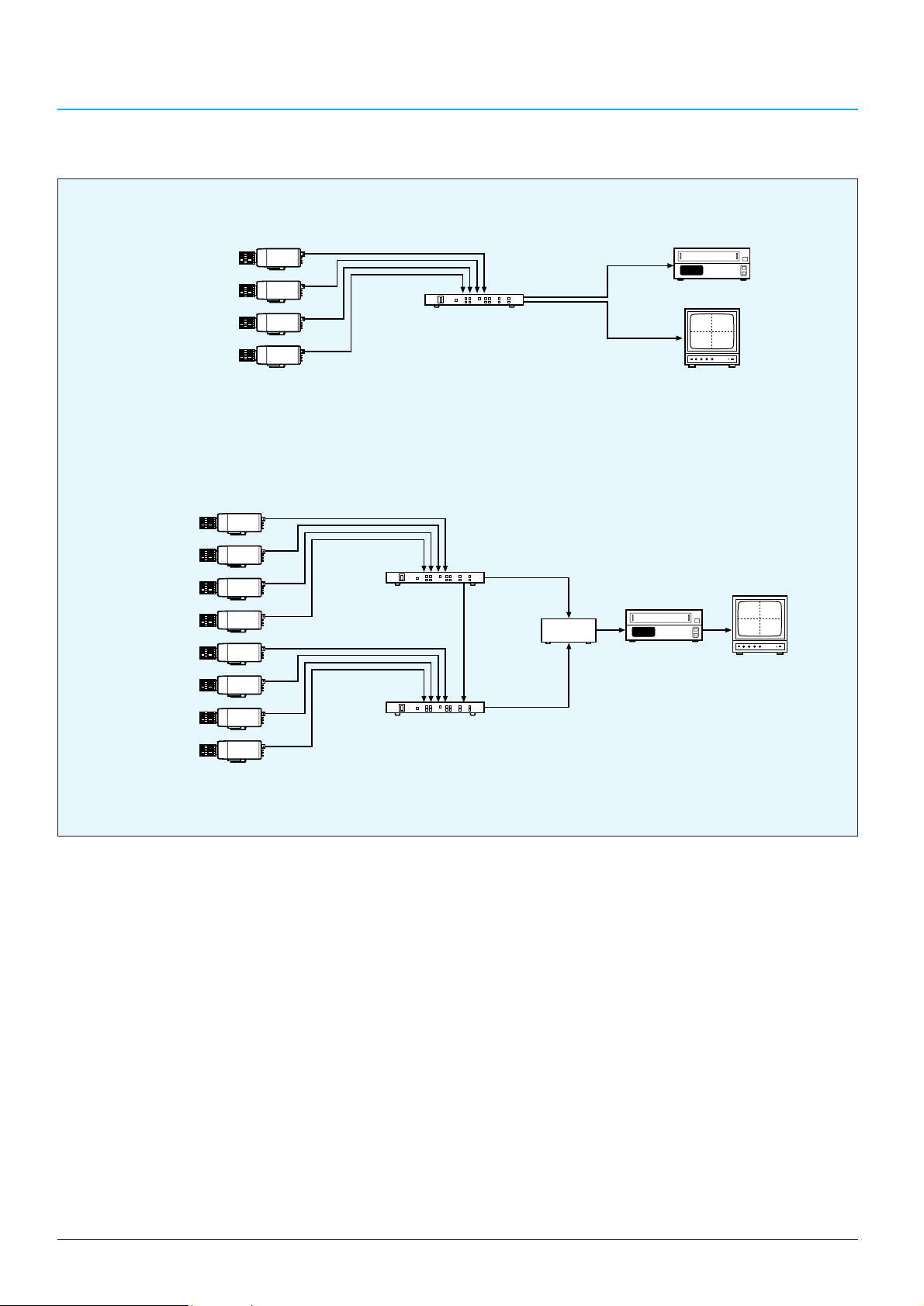
46
SWITCHERS
YS-Q440P Typical System
Video Camera 1
Video Camera 2
Video Camera 3
Video Camera 4
Video Monitor
Video 1
Video 3
Video 2
Video 4
Time Lapse VCR
VIDEO IN 1 to 4
YS-Q440/P
VIDEO OUT 1
VIDEO OUT 2
1. Single YS-Q440P operation
2. YS-Q440P operation with sequential switcher
Video Camera 1
Video Camera 2
Video Camera 3
Video Camera 4
Video Camera 5
Video Camera 6
Video Camera 7
Video Camera 8
VIDEO IN 1 to 4
YS-Q440/P
VIDEO IN 1 to 4
YS-Q440/P
Sync OUT
Sync IN
Quad OUT
Sequential
Switcher
Quad OUT
Time Lapse VCR
Video 1
Video 2
Video 3
Video 4
Video Monitor
Page 43
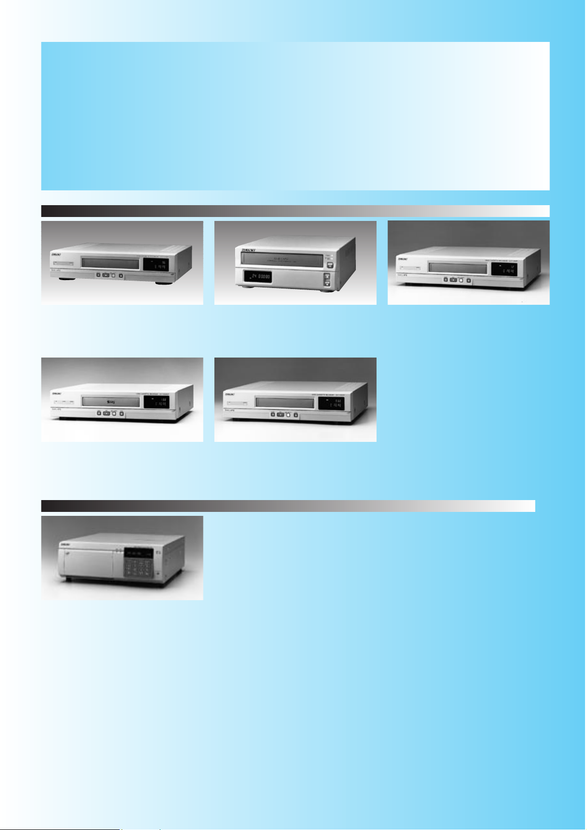
47
SVT -L230P
VHS
RealAction recording
Max. 96 hour recording with E-240 tape
SVT -124P
VHS
compact
Max. 24 hour recording with E-180 tape
SVT -1000P
VHS
Max. 72 hour recording with E-180 tape
Analog time-laspe VCRs
Quick Reference
TIME-LAPSE VIDEO RECORDERS
Keeping a permanent record of events and alarms requires specialized VCRs,
and the expanding range of Sony surveillance products now includes six models.
The family of VCRs divides into two categories: analog time-lapse and digital time-lapse.
The five analog models each have a unique set of features to suit different surveillance
applications. The digital time-lapse recorder, the HSR-1P, uses the advantages of digital
recording to provide outstanding functionality and enhanced picture quality.
SVT -S3050P
S-VHS
Max. 168 hour recording with E-180 tape
SVT -5050P
VHS
Max. 960 hour recording with E-180 tape
HSR-1P
Hybrid recording using hard disk drive and DV tape
Built-in multiplexer
Pre-alarm recording
Digital time-lapse VCR
Page 44
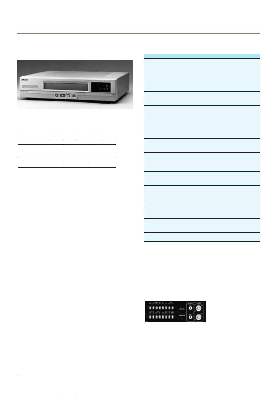
48
TIME LAPSE VIDEO RECORDERS
SVT-L230P
General
Mass: 5.8 kg (12 lb 9 oz)
Dimensions: 420 (W) x 100 (H) x 349 (D) mm
(16 5/8 x 4 x 13 1/2 inches)
Power requirements: AC 220 to 240 V, 50 Hz
Power consumption: 17 W
Operating humidity: Less than 80%
System
Video signal: CCIR standard (monochrome)/PAL (colour)
Recording/playback system:
Rotary four-head helical scanning system
Tape speed: 11.70 mm/second (6 or 8-hour mode)
Recording/Playback mode:
8, 24, 40, 64, 96 hours (with a E-240 tape)
6, 18, 30, 48, 72 hours (with a E-180 tape)
Fast forward/Rewind time:
Approx. 2.5 minutes (with an E-180 tape)
Video
Input: 1.0 Vp-p, 75 Ω, unbalanced (BNC type)
Output: 1.0 Vp-p, 75 Ω, unbalanced (BNC type)
Horizontal resolution: Colour mode: More than 240 TV lines
Black & White mode: More than 320 TV lines
Signal-to-noise ratio: 42 dB
Audio
Audio recording system: Monaural
Input: -7.8 dBu, 47 kΩ (phono jack)
Output: -7.8 dBu, 600 Ω (phono jack)
Microphone input: -60 dBu, 600 Ω (ø3.5 mm mini jack)
Distortion: Less than 4%
Audio signal-to-noise ratio: 40 dB
Others
Alarm input: Low level, Terminal trip x 1
Alarm output: +5 V, 5.7 kΩ (Low active), Terminal trip x 1
Switch output: +5 V, 5.7 kΩ, Terminal trip x 1
Tape end output: +5 V, 5.7 kΩ (Low active), Terminal trip x 1
Warning output: +5 V, 5.7 kΩ (Low active), Terminal trip x 1
Timer output: +5 V, 5.7 kΩ (High active), Terminal trip x 1
External timer input: Low level, Terminal trip x 1
Clock set output: +5 V, 5.7 kΩ (Low active), Terminal trip x 1
Clock set input: Low level
Series output: +5 V, 5.7 kΩ (Low active), Terminal trip x 1
Remote control input: ø3.5 mm mini jack (x 1)
•Sony’s RealAction technology allows high density
recording of 16.6 fields per second
•Maximum 96-hour time lapse recording mode is
available with a 240-minute tape
•Audio recording and playback are possible in 8, 24,
40-hour modes (E-240) and in 6, 18, 30-hour modes
(E-180)
•Built-in time and date generator allows time and date
information to be displayed along with the Alarm count
and Recording/Playback speed
•Various recording modes such as Auto Repeat
Recording, Timer Recording, Alarm Recording and
Series Recording for versatile situations
•Dalight Saving Time setting function
•Holiday setting function
•Camera switcher interface
•Quick recording check function
•By using alarm recall, scan and search functions,
pictures recorded during alarm mode can be easily
checked
•Field-by-field picture playback capability
•External timer input capability
•Automatic clock adjusting is possible when several
VTRs are used
•On-screen display permits easy-to-follow operation
•Auto head cleaning function
•Tape before-end/Tape-end signal output capabilities
•Warning signal output capability
•Buzzer function
•Power-failure protection for up to 30 days
•Security lock function for avoiding accidental operation
errors
•Loop-through capability enables video and audio to be
output through to the monitor automatically
•Clog detection function
•Remote control capability of basic operational functions
through ø3.5mm mini jack
•External control capability via an optional RS-232C
interface
Time Lapse Videocassette Recorder
SVT-L230P
TIME MODE (h) 8 24 40 64 96
INTERVAL(s) 1/50 0.06 0.1 0.18 0.26
Specifications
Supplied Accessories
AC power cable (1)
Operation manual (1)
Optional Accessories
SVT-RM10 Remote Control Unit
RSE-232C interface board SVT-RS1A
TLV parts kit TPK-888P
•Maximum 72-hour time lapse recording mode is
available with a 180-minute tape
TIME MODE (h) 6 18 30 48 72
INTERVAL(s) 1/50 0.06 0.1 0.18 0.26
•Adaptive Picture Control (APC) delivers optimum
picture quality to the recording image
Rear Panel
Page 45
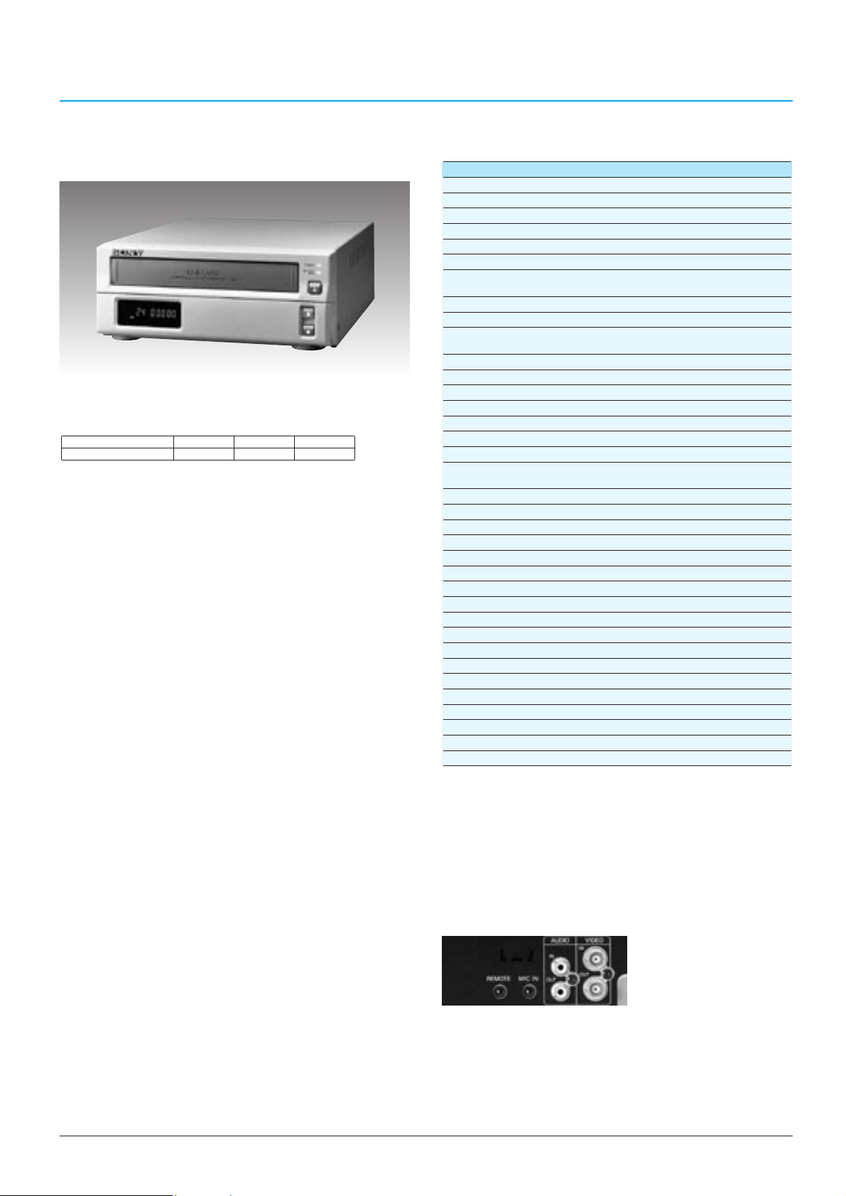
49
TIME LAPSE VIDEO RECORDERS
SVT-124P
General
Tape format: VHS
Power requirements: AC 220 to 240 V, 50/60 Hz
Power consumption: 18 W
Operating temperature: 5 to 40°C (41°F to 104°F)
Operating humidity: Less than 80%
Dimensions: 240 (W) x 96.5 (H) x 333 (D) mm
(9 1/2 x 3 7/8 x 13 1/8 inches)
Mass: Approx. 3.8 kg (8 lb 6 oz)
Tape speed: 23.39 mm/sec (3-hour mode)
Recording/Playback time:
3, 12, 24 hours
(with an SE/E-180 tape)
Alarm recording speed: 3-hour mode
Alarm recording duration: 20 s, 40 s, 1 m, 2 m, 3 m, 5 m, CC*,TRIG
Fast forward/rewind time: Approx. 2.5 minutes (with an SE/E-180 tape)
Video
Recording system: Rotary two-head helical scanning system
Input: BNC: 1.0 Vp-p, 75 Ω, unbalanced
Output: BNC: 1.0 Vp-p, 75 Ω, unbalanced
Horizontal resolution: Colour mode: More than 240 TV lines
Black & White mode: More than 320 TV lines
Signal-to-noise: 43 dB
Audio
Audio recording system: Monaural
Audio recording mode: 3, 12 and 24-hour mode
Input: -7.8 dBu, 47 kΩ (phono jack)
Output: -7.8 dBu, 600 Ω (phono jack)
Microphone input: -60 dBu, 600 Ω (ø3.5 mm minijack)
Distortion: Less than 4%
Audio signal-to-noise: 42 dB
Others
Alarm input: Low level
Alarm output: +5 V, 5.7 kΩ (Low active)
Switch output: +5 V, 5.7 kΩ (Low active)
Tape end output: +5 V, 5.7 kΩ (Low active)
Warning output: +5 V, 5.7 kΩ (Low active)
External timer input: Low level
Remote/Tally: Stereo mini pin
AC input: 3-pin inlet
Notes: *Stays an alarm for as long as the alarm input remains active.
0 dBu = 0.775 Vrms
Time Lapse Videocassette Recorder
SVT-124P
Specifications
•Two different time lapse recording/playback modes are
available in addition to the standard mode (3 hours
time mode) with a normal 180-minute tape
•Compact body with a 240 mm width
•Adaptive Picture Control (APC) delivers optimum
picture quality to the recording image
•Audio recording and playback are possible in 3, 12 and
24-hour modes
•Built-in time and date generator allows time and date
information to be displayed along with the Alarm count
and Recording/Playback speed
•Various recording modes such as Auto Repeat
Recording, Timer Recording and Alarm Recording for
versatile situations
•Holiday setting function
•Daylight Saving Time setting function
•Camera switcher interface
•Quick recording check function
•By using alarm recall and scan functions, pictures
recorded during alarm mode can be easily checked
•Field-by-field picture playback capability
•External timer input capability
•Automatic clock adjusting is possible when several
VCRs are connected
•On-screen display permits easy-to-follow operation
•Auto head cleaning function
•
Tape before-end signal output/Tape-end output capability
•Warning signal output capability
•Buzzer setting function
•Power-failure protection for up to 30 days
•Security lock function for avoiding accidental operation
errors
•Clog detection function
•Remote control capability of basic operational functions
through ø3.5mm mini jack
(optional Remote Control Unit SVT-RM10)
TIME MODE (h) 3 12 24
INTERVAL(s) 1/50 0.1 0.18
Supplied accessories
AC power cord (1)
Operation manual (1)
Optional accessory
SVT-RM10 Remote Control Unit
TLV parts kit TPK-953P
Rear Panel
Page 46
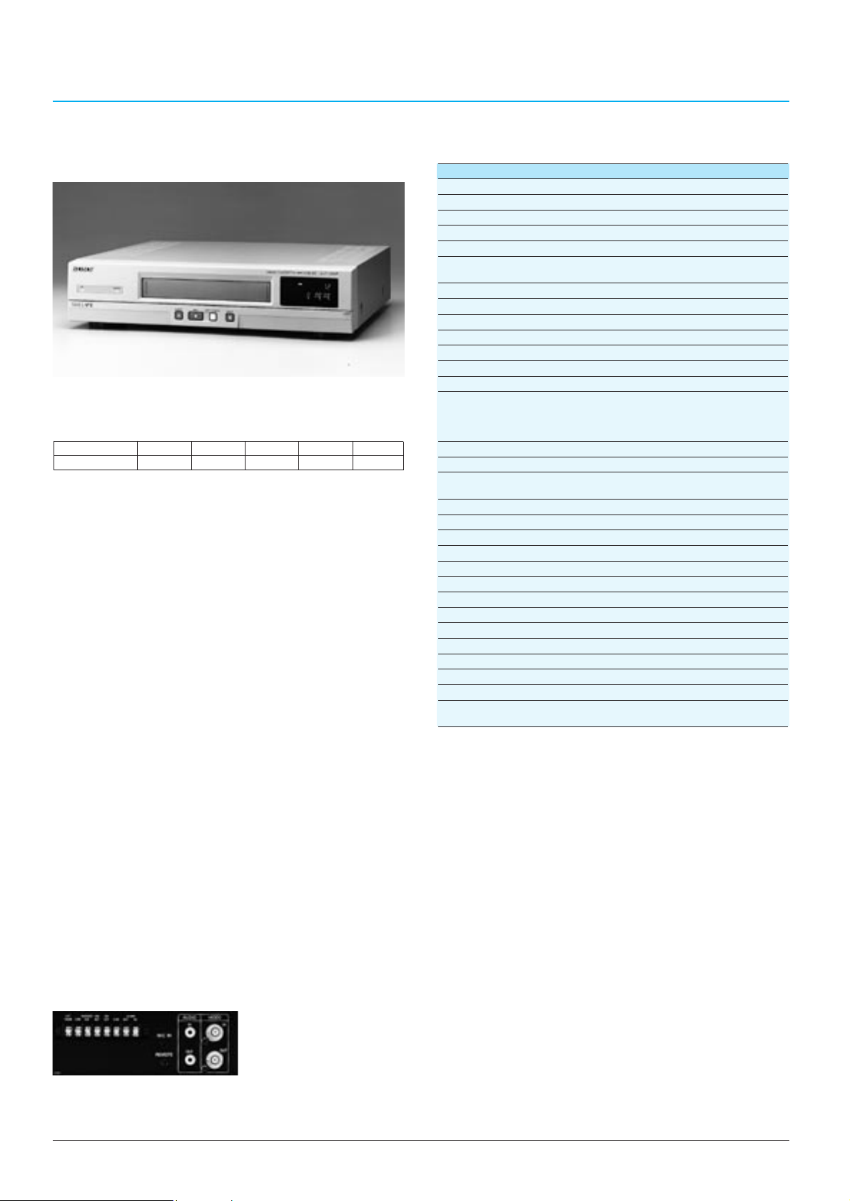
50
TIME LAPSE VIDEO RECORDERS
Supplied accessories
AC power cord (1)
Operation manual (1)
Optional accessory
SVT-RM10 Remote Control Unit
RS-232C interface board SVT-RS1A
TLV parts kit TPK-887P
SVT-1000P
General
Power requirements: AC 220 to 240 V, 50/60 Hz
Power consumption: 18 W
Operating temperature: 5 to 40°C (41 to 104°F)
Operating humidity: Less than 80%
Dimensions: 420 (W) x 100 (H) x 349 (D) mm
(16 5/8 x 4 x 13 3/4 inches)
Mass: Approx. 5.5 kg (12 lb 2 oz)
Tape speed: 23.39 mm/sec (3-hour mode)
Recording/playback time: 3, 12, 24, 48 and 72 hours (with an E-180 tape)
Alarm recording speed: 3, 12-hour mode, NC*
1
Alarm recording duration: 20 s, 1 m, CC*
2
Fast forward/rewind time: Approx. 4 minutes (with an E-180 tape)
Video
Recording Playback system:
Rotary four-head helical scanning system
Luminance signal: FM recording
Colour signal: Low-pass band-pass
transformation direct recording
Input:
1.0 Vp-p, 75 Ω, unbalanced, sync negative (BNC type)
Output:
1.0 Vp-p, 75 Ω, unbalanced, sync negative (BNC type)
Horizontal resolution: Colour mode: More than 240 TV lines
Black & White mode: More than 320 TV lines
Signal-to-noise ratio: 43 dB
Audio
Audio recording mode: 3, 12 and 24-hour mode
Input: -7.8 dBu, 47 kΩ, unbalanced (phono jack)
Output: -7.8 dBu, 600 Ω, unbalanced (phono jack)
Microphone input: -60 dBu, 600 Ω (ø3.5 mm minijack)
Others
Alarm input: Low level
Alarm output: +5 V, 5.7 kΩ (Low active)
Switch output: +5 V, 5.7 kΩ (Low active)
Tape end output: +5 V, 5.7 kΩ (Low active)
Warning output: +5 V, 5.7 kΩ (Low active)
External timer input: Low level
Control terminals: ø3.5 mm mini jack
Optional RS-232C interface (D-sub 9-pin)
Notes: *1No change of recording speed
*2Stays an alarm for as long as the alarm input remains active.
0 dBu=0.775 Vrms
•Adaptive Picture Control (APC) delivers optimum
picture quality to the recording image
•A tape recorded in the 3-hour mode can be played
back by any VHS VCR
•Audio recording and playback are possible in 3, 12 and
24-hour modes
•Built-in time and date generator allows time and date
information to be displayed along with the Alarm count
and Recording/Playback speed
•
Various recording modes such as Auto Repeat Recording,
Timer Recording and Alarm Recording for versatile situations
•By using alarm recall and scan functions, pictures
recorded during alarm mode can be easily checked
•Holiday setting function
•Daylight Saving Time setting function
•Quick recording check function
•Field-by-field picture playback capability
•External timer input capability
•On-screen display permits easy-to-follow operation
•Auto head cleaning function
•Tape before-end signal output capability
•Warning signal output capability
•Buzzer setting function
•Power-failure protection for up to 30 days
•
Security lock function for avoiding accidental operation errors
•
External control capability via an optional RS-232C interface
•Remote control capability of basic operational functions
through ø3.5 mm mini jack
•4 different time lapse recording/playback modes are
available in addition to the standard mode (3 hours
time mode) with a normal 180-minute tape
Note: In time lapse modes, it is possible to additionally record three hours longer than the original modes.
Time Lapse Videocassette Recorder
SVT-1000P
Specifications
TIME MODE (h)
312244872
INTERVAL(s)
1/50 0.1 0.18 0.34 0.5
Rear Panel
Page 47
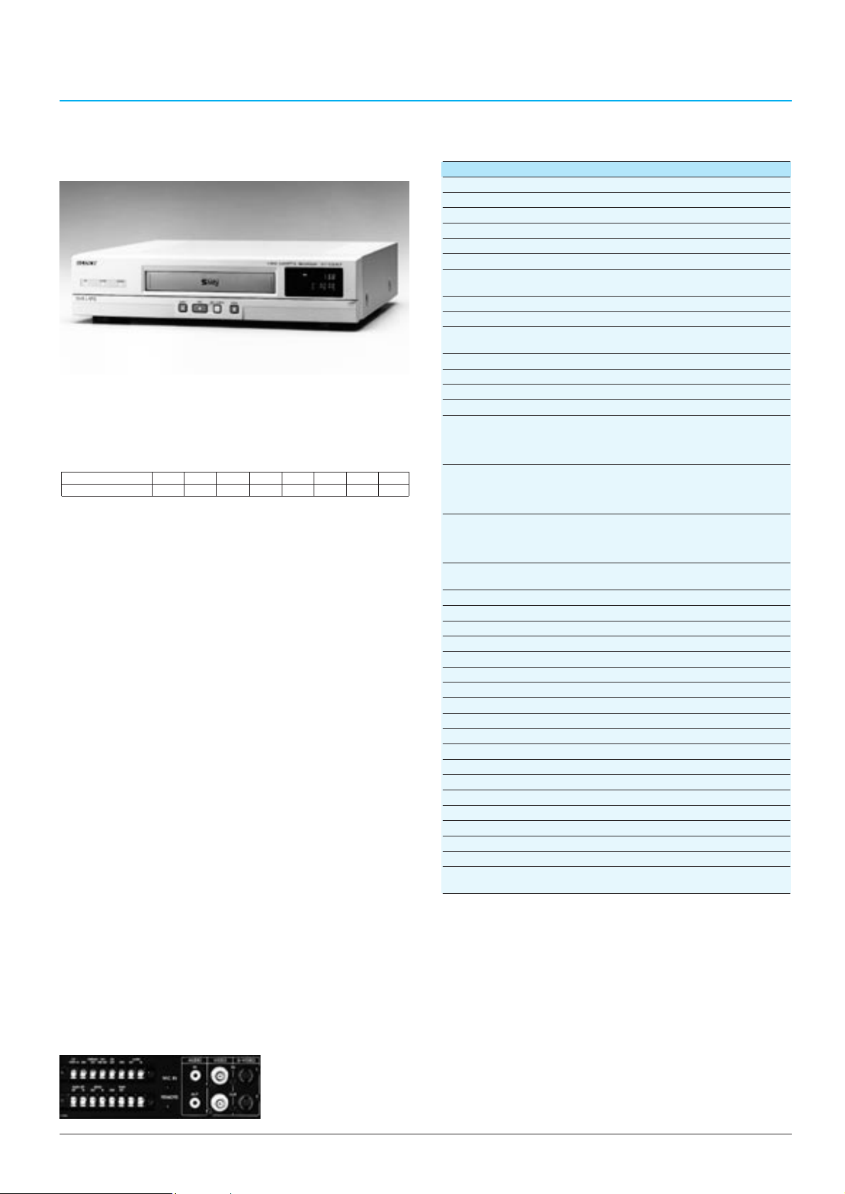
51
TIME LAPSE VIDEO RECORDERS
•Adaptive Picture Control (APC) delivers optimum
picture quality to the recording image
•A tape recorded in the 3-hour mode can be played
back by any S-VHS or VHS VCR
•Audio recording and playback are possible in 3, 12 and
24-hour modes
•Built-in time and date generator allows time and date
information to be displayed along with the Alarm count
and Recording/Playback speed
•Various recording modes such as Auto Repeat
Recording, Timer Recording and Alarm Recording for
versatile situations
•Holiday setting function
•Daylight Saving Time setting function
•Quick recording check function
•
By using alarm recall and scan functions, pictures
recorded during alarm mode can be easily checked
•Field-by-field picture playback capability
•External timer input capability
•Automatic clock adjusting is possible when several
VCRs are connected
•On-screen display permits easy-to-follow operation
•Auto head cleaning function
•Tape before-end signal output capability
•Warning signal output capability
•Buzzer setting function
•Power-failure protection for up to 30 days
•
Security lock function for avoiding accidental operation errors
•
External control capability via an optional RS-232C interface
•Remote control capability of basic operational functions
through ø3.5mm mini jack
SVT-S3050P
General
Tape format: S-VHS or VHS
Power requirements: AC 220 to 240 V, 50/60 Hz
Power consumption: 18 W
Operating temperature: 5 to 40°C (41 to 104°F)
Operating humidity: Less than 80%
Dimensions: 420 (W) x 100 (H) x 349 (D) mm
(16 5/8 x 4 x 13 1/2 inches)
Mass: Approx. 5.8 kg (12 lb 9 oz)
Tape speed: 23.39 mm/sec (3-hour mode)
Recording/playback time:
3, 12, 24, 48, 72, 96, 120 and 168 hours
(with an SE/E-180 tape)
Alarm recording speed: 3, 12-hour mode, NC*
1
Alarm recording duration: 20 s, 1 m, CC*
2
Fast forward/rewind time: Approx. 4 minutes (with an SE/E-180 tape)
Video
Recording Playback system:
Rotary four-head helical scanning system
Luminance signal: FM recording
Colour signal: Low-pass band-pass
transformation direct recording
Input: BNC: 1.0Vp-p, 75 Ω, unbalanced
S -VIDEO: Mini DIN 4-pin
Y: 1.0Vp-p, 75 Ω, sync negative
C: 0.3 Vp-p, at burst level, 75 Ω
Output: BNC: 1.0 Vp-p, 75 Ω, unbalanced
S -VIDEO: Mini DIN 4-pin
Y: 1.0 Vp-p, 75 Ω, sync negative
C: 0.3 Vp-p, at burst level, 75 Ω
Horizontal resolution:
Colour mode: More than 400 TV lines (S-VHS)
Black & White mode: More than 400 TV lines (S-VHS)
Signal-to-noise ratio: 45 dB (S-VHS)
Audio
Audio recording mode: 3, 12 and 24-hour mode
Input: -7.8 dBu, 47 kΩ (phono jack)
Output: -7.8 dBu, 600 Ω (phono jack)
Microphone input: -60 dBu, 600 Ω (ø3.5 mm minijack)
Others
Alarm input: Low level
Alarm output: +5 V, 5.7 kΩ (Low active)
Switch output: +5 V, 5.7 kΩ (Low active)
Tape end output: +5 V, 5.7 kΩ (Low active)
Warning output: +5 V, 5.7 kΩ (Low active)
Timer output: +12 V, 5.7 kΩ (high active)
External timer input: Low level
Clock set output: +5 V, 5.7 kΩ (Low active)
Clock set input: Low level
Series output: +5 V, 5.7 kΩ (Low active)
Series input: Low level
Control terminals: ø3.5 mm mini jack
Optional RS-232C interface (D-sub 9-pin)
Notes: *1No change of recording speed
*2
Stays an alarm for as long as the alarm input remains active.
0 dBu = 0.775 Vrms
S-VHS Time Lapse Videocassette Recorder
SVT-S3050P
Specifications
•
High horizontal resolution of 400TV lines using S-VHS format
•Excellent signal-to-noise ratio of 45 dB
•7 different time lapse recording/playback modes are
available in addition to the standard mode (3 hours
time mode) with a normal 180-minute tape
Note: In time lapse modes, it is possible to additionally record three hours longer than the original modes.
TIME MODE (h) 3 12 24 48 72 96 120 168
INTERVAL(s) 1/50 0.1 0.18 0.34 0.5 0.66 0.82 1.14
Supplied accessories
AC power cord (1)
Operation manual (1)
Optional accessory
SVT-RM10 Remote Control Unit
RS-232C interface board SVT-RS1A
TLV parts kit TPK-885P
Rear Panel
Page 48
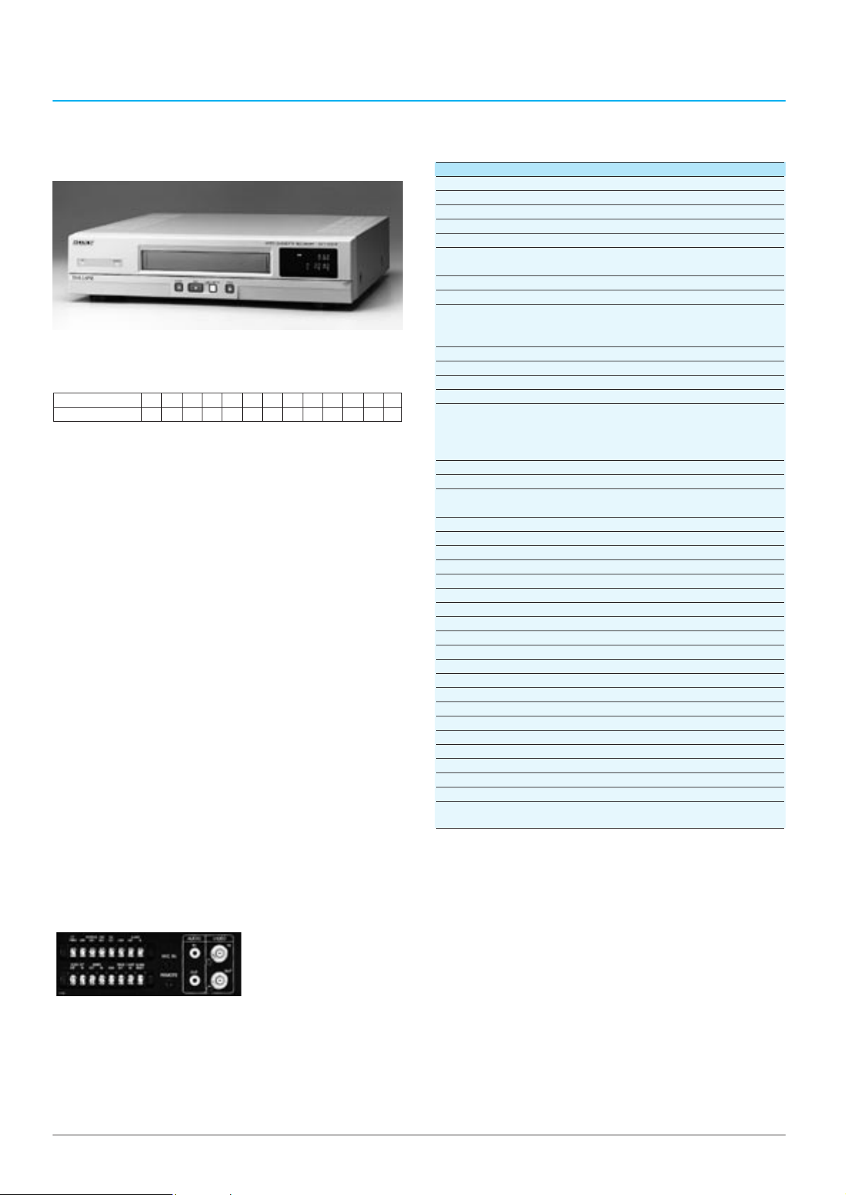
52
TIME LAPSE VIDEO RECORDERS
SVT-5050P
General
Power requirements: AC 220 to 240 V, 50/60 Hz
Power consumption: 18 W
Operating temperature: 5 to 40°C (41 to 104°F)
Operating humidity: Less than 80%
Dimensions: 420 (W) x 100 (H) x 349 (D) mm
(16 5/8 x 4 x 13 3/4 inches)
Mass: Approx. 5.5 kg (12 lb 2 oz)
Tape speed: 23.39 mm/sec (3-hour mode)
Recording/playback time: 3, 12, 24, 48, 72, 96, 120, 168, 240, 360, 480,
720 and 960 hours (with an E-180 tape)
(One shot mode is also available)
Alarm recording speed: 3, 12-hour mode, NC*
1
Alarm recording duration: 20 s, 40 s, 1 m, 2 m, 3 m, 4 m, 5 m, CC*
2
Fast forward/rewind time: Approx. 4 minutes (with an E-180 tape)
Video
Recording Playback system:
Rotary four-head helical scanning system
Luminance signal: FM recording
Colour signal: Low-pass band-pass
transformation direct recording
Input: 1.0 Vp-p, 75 Ω, unbalanced (BNC type)
Output: 1.0 Vp-p, 75 Ω, unbalanced (BNC type)
Horizontal resolution: Colour mode: More than 240 TV lines
Black & White mode: More than 350 TV lines
Signal-to-noise ratio: 43 dB
Audio
Audio recording mode: 3, 12 and 24-hour mode
Input: -7.8 dBu, 47 kΩ (phono jack)
Output: -7.8 dBu, 600 Ω (phono jack)
Microphone input: -60 dBu, 600 Ω (ø3.5mm mini jack)
Others
Alarm input: Low level
Alarm output: +5 V, 5.7 kΩ (Low active)
Switch output: +5 V, 5.7 kΩ (Low active)
Tape end output: +5 V, 5.7 kΩ (Low active)
Warning output: +5 V, 5.7 kΩ (Low active)
Timer output: +12 V, 5.7 kΩ (high active)
External timer input: Low level
Clock set output: +5 V, 5.7 kΩ (Low active)
Clock set input: Low level
Series output: +5V, 5.7 kΩ (Low active)
Series input: Low level
One-shot input: Low level
Alarm reset: Low level
Control terminals: ø3.5 mm mini jack
Optional RS-232C interface (D-sub 9-pin)
Notes *1No change of recording speed
*2Stays an alarm for as long as the alarm input remains active.
0 dBu=0.775 Vrms
•12 different time lapse recording/playback modes are
available in addition to the standard mode (3 hours
time mode) with a normal 180-minute tape
•Adaptive Picture Control (APC) delivers optimum
picture quality to the recording image
•A tape recorded in the 3-hour mode can be played
back by any VHS VCR
•Audio recording and playback are possible in 3,12 and
24-hour modes
•Built-in time and date generator allows a required
scene to be easily searched by presetting the desired
time and date
•
Multiple recording modes such as Auto Repeat
Recording, Timer Recording, Alarm Recording, One-shot
Recording and Series Recording for versatile situations
•Holiday setting function
•Daylight Saving Time setting function
•Quick recording check function
•By using alarm recall/scan/search functions, pictures
recorded during alarm mode can be easily checked
•Field-by-field picture playback capability
•External timer input capability
•Automatic clock adjusting is possible when several
VCRs are connected
•On-screen display permits easy-to-follow operation
•Auto head cleaning function
•Tape before-end signal output capability
•Warning signal output capability
•Buzzer setting function
•Power-failure protection for up to 30 days
•
Security lock function for avoiding accidental operation errors
•
External control capability via an optional RS-232C interface
•Remote control capability of basic operational functions
through ø3.5 mm mini jack
Time Lapse Videocassette Recorder
SVT-5050P
TIME MODE (h)
3 12 24 48 72 96 120 168 240 360 480 720 960
INTERVAL(s)
1/50 0.1 0.18 0.34 0.5 0.66 0.82 1.14 1.62 2.42 3.22 4.82 6.42
Specifications
Supplied Accessories
AC power cord (1)
Operation manual (1)
Optional Accessory
SVT-RM10 Remote Control Unit
RS-232C interface board SVT-RS1A
TLV parts kit TPK-887P
Note: In time lapse modes, it is possible to additionally record three hours longer than the original modes.
Rear Panel
Page 49

53
TIME LAPSE VIDEO RECORDERS
ANALOG TIME LAPSE VCR FEATURE COMPARISON CHART
SVT-L230P SVT-124P SVT-1000P SVT-S3050P SVT-5050P
Format VHS VHS VHS S-VHS/VHS VHS
Recording Speed
up to 72 (E-180)/up to 96 (E-240)
up to 24 (E-180) up to 72 (E-180) up to 168 (E-180) up to 960 (E-180)
Adaptive Picture Control
YES YES YES YES YES
Audio Playback 6, 18, 30 3, 12, 24 3, 12, 24 3, 12, 24 3, 12, 24
Horizontal Resolution B/W: 320 CLR: 240 B/W: 320 CLR: 240 B/W: 320 CLR: 240 B/W: 400 CLR: 400 B/W: 350 CLR: 240
RS-232C IF (option) YES NO YES YES YES
Video S/N 42 dB 44 dB 43 dB 45 dB 43 dB
FF/REW Time Approx. 2.5 min (E-180) Approx. 2.5 min (E-180) Approx. 4 min (E-180) Approx. 2.5 min (E-180) Less than 4 min (E-180)
Dimensions (mm) 420 x 100 x 349 240 x 96.5 x 333 420 x 100 x 349 420 x 100 x 349 420 x 100 x 349
Mass (kg) 5.8 3.8 5.8 5.8 5.8
Timer REC Daily, Weekly Daily, Weekly Daily, Weekly Daily, Weekly Daily, Weekly
Auto Repeat REC YES YES YES YES YES
Series REC YES NO NO YES YES
One Shot REC NO NO NO NO YES
Field Advance YES (±) YES (+) YES (±) YES (+) YES (±)
Reverse Playback Standard Only NO Standard Only Standard Only Standard Only
Alarm Search YES NO NO NO YES
Alarm Scan/Recall YES YES YES YES YES
Time Date Search YES NO NO NO YES
Memory Back-up 30 days (Lithium batt.) 30 days (Lithium batt.) 30 days (Lithium batt.) 30 days (Lithium batt.) 30 days (Lithium batt.)
REC Check YES YES YES NO NO
Clog derection YES YES NO NO NO
Daylight YES (Auto) YES (Auto) YES (Manual) YES (Manual) YES (Manual)
Holiday Set YES YES YES YES YES
Series In/Out YES NO NO YES YES
Timer OUT YES NO YES YES YES
Warning OUT YES YES YES YES YES
Tape Before End/End YES YES YES YES YES
Clock Adjusting YES NO NO YES YES
Page 50
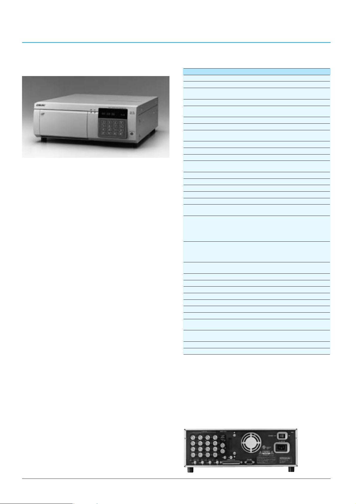
54
TIME LAPSE VIDEO RECORDERS
Supplied accessories
AC power cord (1)
Operation manual (1)
Optional accessory
HSRA-11 (Input Board)
SVRM-100A (Remote Control Unit)
HSR-1P
General
Mass 10 kg (22 lb 1 oz)
Dimensions 355 (W) x 125 (H) x 410 (D) mm
(14 x 5 x 16 1/4 inches)
Power requirements AC 220 V~240 V, 50/60 Hz
Power consumption 80 W (without options)
115 W (with full options)
Operating temperature 5°C ~ 40°C (41°F ~ 104°F)
Operating humidity Less than 80%
Usable tape DV*1 or DVCAM*2 cassette tape
(standard size, mini size)
HDD capacity More than 4.3 GB
System
Video signal CCIR standard, PAL colour
Recording system Rotary two-head helical scanning system
Digital components
Quantization 8-bit
Sampling frequency 13.5 MHz (4:2:0 components)
Recording/Playback time Maximum 9999 hours (Approx. 400 days)
Fast forward/Rewind time Less than 3 min. (with a DV270 tape)
Video
Input VBS, VS (BNC type):
1.0 Vp-p, 75 Ω, unbalanced
Output VBS (BNC type):
1.0 Vp-p, 75 Ω, unbalanced
S-VIDEO (DIN 4-pin):
Y: 1.0 Vp-p, 75 Ω, sync negative
C: 0.3 Vp-p, 75 Ω, at burst level
Quality mode SUPER, HIGH, MIDDLE and LOW mode
(selectable) (Field-by-field recording)
HYPER mode
(Frame-by-frame recording with a trigger signal)
Horizontal resolution More than 500 TV lines
(HYPER and SUPER mode)
Signal-to-noise ratio More than 48 dB
Built-in Multiplexer
Input 4 inputs (up to 16 inputs with optional boards)
Output 2 outputs
Split screen display 9 patterns
Connectors
Parallel input/output D-SUB 37-pin (1)
Input: 24 terminals to be freely assigned
(Alarm, Clock set, Series rec, Alarm cancel, etc.)
Output: 8 terminals to be freely assigned
(Auto off, Tape end, Series rec, Rec tally, ect.)
Power output: +12 V (max 100 mA)
Control S Stereo mini (1)
Notes: *1 The recorded tape by the HSR-1P cannot be played back on DV equipment.
*2 ADVCAM 184-minute tape can be used with the HSR-1P. It has the same storage capacity as
that of a DV 270-minute tape.
•Hybrid configuration of HDD and DV tape drive
•Four alternative quality modes: Super, High ,Middle and
Low modes
•Excellent picture quality provided by super mode with a
horizontal resolution of more than 500 TV lines (Super
mode)
•Large storage capacity(more than 60 GB) and long
recording time by using DV cassette tape(270-minute
tape) as a storage medium
•High refresh rate for recording of each camera
•
High reliability on tape transport mechanism and heads offered
by the hybrid configuration of HDD and DV tape drive.
•Compact body which matches that of a 14-inch monitor
•Compact storage medium which requires less space
•Up 16 camera inputs provided by installing optional
HSRA-11
•Built-in duplex multiplexing capability which allows
recording and monitoring of up to 16 camera inputs
independently.
•A variety of monitoring patterns
•Two monitoring outputs for simultaneous playback on the
first monitor and monitoring on the second monitor
•Five preset recording modes to be flexibly combined
with picture quality mode, tape length, recording time,
number of camera inputs and the recording cycle of
each camera.
•Flexible camera assignment
•RS-232C interface for PC control
•Freely configurable 37-pin parallel port
•Flexibility in alarm mode
•Continuous recording function without breaks even while
changing or rewinding the tape
•Sophisticated security functions
•Water mark
•
Intelligent search functions: time/date search, alarm search,
specific user data search and noiseless picture search
•Pre Alarm recording capability for event recording
•Power On recording capability
•Frame recording in hyper mode
Digital Surveillance Recorder
HSR-1P
Specifications
Rear Panel
Page 51

55
TIME LAPSE VCR OPTIONAL ACCESSORIES
•Works with all Sony time lapse VCRs
•Provides wired remote control operation for
REC/PLAY/STOP/REW/ FF/REV/PLAY/PAUSE
•MENU button and REC/PLAY speed button are also
available
•Cable length: 2.4 m
Remote Control Unit
SVT-RM10
•When installed in the SVT-5050P, SVT-3050P,
SVT-1000P, and SVT-L230P, this board allows these
recorders to be remotely controlled from computers
•Connectable with common RS-232C cable (male type)
•REC CHECK function is available
RS-232C Interface Board
SVT-RS1A
SVT- Series VCR TLV Parts Kit
SVT-L230P TPK-888P
SVT-124P TPK-953P
SVT-1000P TPK-887P
SVT-5050P TPK-887P
SVT-S3050P TPK-S885P
TLV Parts kit
•Parts kit for all SVT time lapse VCRs
•Includes all the parts required for a 10,000 hour
maintenance service, including VCR cylinder and brake
assembly
•Provides wired remote control operation for HSR-1P
•STOP/REC/PAUSE/REW/PLAY/FFWD/JOG/SHUTTLE
operation
Remote Control Unit
SVRM-100A
•Up to 16 camera inputs available when three optional
input board, each having four inputs, are installed (The
HSR-1P has one input board pre-installed)
Input Board
HSRA-11
Page 52

56
Page 53
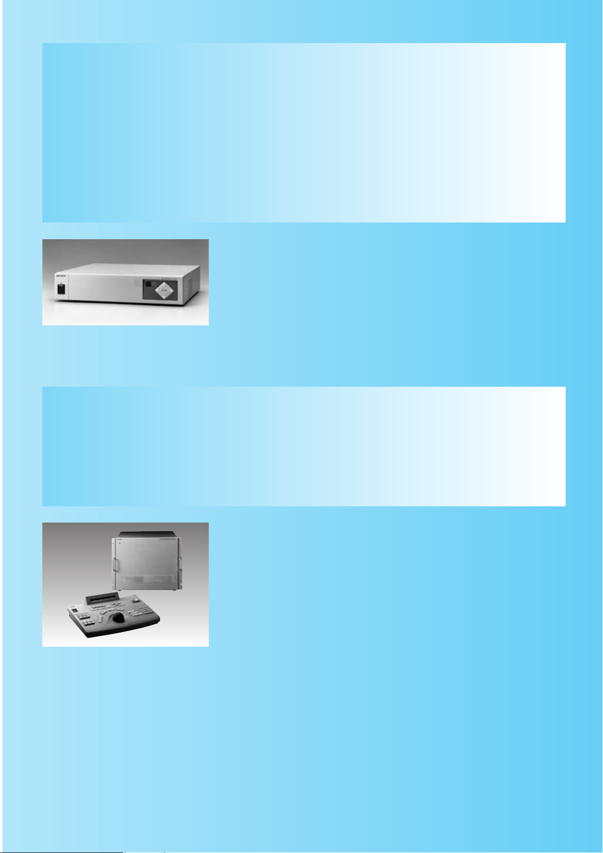
PMS-500P/400P
Tranceiver (PMS-500P)
Transmitter (PMS-400P)
Quick Reference
MONITORING CODECS AND
SYSTEM CONTROLLER
Monitoring Codecs
The PMS (Picture Monitoring System) monitoring codecs have been designed especially for
remote site surveillance applications. The PMS-500P tranceiver and PMS-400P transmitter
take advantage of the latest advances in ISDN telecommunications and image processing
technology. Instead of still pictures, these codecs deliver smooth, clear, full colour video at a
maximum of 15 frames per second together with audio and control data.
CSP-5000E
with CSPK-5000E Keyboard
57
System Controller
The CSP-5000E is a highly programmable, easy-to-use CCTV matrix controller. It is designed
for middle to large-scale surveillance systems and supports up to 128 camera inputs and 32
monitor outputs. Versatile camera switching and support of coaxial and twisted pair
telemetry makes it the ideal choice for shopping centres, banks, office building and traffic
control applications.
Page 54

58
MONITORING CODECS
Monitoring Codec
PMS-500P/400P
*
PMS-500P (Receiver/Transmitter)
PMS-400P (Transmitter)
*These models are available only in Europe. For details, please contact your nearest Sony office.
Video Voice Control data
Send Receive Send Receive Send Receive
PMS-500P Yes Yes Yes Yes Yes Yes
PMS-400P Yes No Yes Yes Yes Yes
•PMS-500P and PMS-400P Comparison
PMS-500P
PMS-400P
Rear Panel
Supplied Accessories
Operating instructions (1)
AC power cord (1)
Optional Accessory
RM-R500 remote contorol unit (for PMS-500P only)
(Both PMS-500P/400P)
• Transmission of smooth and clear, video at a maximum
of 15 frames per second via ISDN line
• Selectable video mode (Fast/Normal/Fine) in
monitoring
• Accepts 8 camera inputs which are selectable from a
control centre or local terminals
• I/O port to control camera pan/tilt and zoom lens
•
Relay output port to control external devices (ie; door, light)
• Transmission and receiving capability of audio which
allows conversation between two sites
• When an alarm signal is input to a terminal, it
automatically activates the control centre to switch the
monitor to watch that terminal
• Easy connection, just by connecting to an ISDN
modular jack
• Compatible with a wide range of cameras, monitors,
and TLV equipment
• Remote control with the RM-R500 Remote Control Unit
• Password protection
• An RS-232C serial interface for PC control
• Remote diagnostics
RM-R500 Remote Control Unit
Page 55
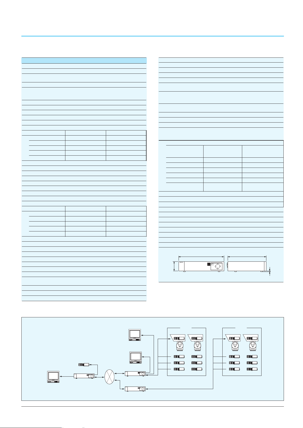
59
MONITORING CODECS
Specifications
PMS-500P/400P
Video
Coding H.261 (ITU-T recommendation)
Operating bandwidth 56 kbps/64 kbps/112 kbps/128 kbps
…
384 kbps
Frame rate Max. 15 frames per second
Picture elements CIF:Luminance (Y) 352 pixels ´ 288 lines
Colour difference (B-Y, R-Y) 176 pixels
´ 144 lines
Colour system PAL (mutually connectable with NTSC)
PinP PMS-500P only
Input
Video In/Ext. Video In 1 Vp-p, 75 Ω, sync negative (BNC type)
Video Out/Through Out 1 Vp-p, 75 Ω, sync negative (BNC type)
Monitor Out 1 Vp-p, 75 Ω, sync negative (BNC type)
Input connectors
PMS-500P PMS-400P
Video In 88
Ext. Video In 11
Video Out 1-
Monitor Out 11
Audio
Coding G.728 (ITU-T recommendation)
Transfer rate 16 kbps
Bandwidth 3.4 kHz
Input
Mic In
-60 dBu/600 Ω, balanced (4-pin round connector)
Headphone Mic In -60 dBu/4.7 kΩ, unbalanced (minijack)
Line Out Variable, 4.7 kΩ (phono)
Headphone SP Out Variable, 72 Ω (minijack)
Input connectors
PMS-500P PMS-400P
Mic In 11
Headphone Mic In 11
Line Out 11
Headphone SP Out 11
Control procedure coding standards
H.242 System for Establishing Communication
H.320 Overall System
H.230 Control and Indication Signal
H.221 Framing and Signalling Structure
Communications interface
Network
Multiplexing Video, audio, data
Transmission rate ISDN interface, 1B/2B
V35 with RS-366 (56 k - 384 k)
Network connectors
ISDN BRI RJ45
V35 with RS-366 36-pin half-pitch connector (´2)
Computer Control Port
Interface RS-232C
Baud rate 1200/2400/4800/9600/19200/38400 bps
User data I/O
I/O parallel
Alarm input D-sub 9-pin
TTL input, pull-up resistance 10 kΩ
Relay control D-sub 9-pin
Output mode: Open collector (40 V, 40 mA)
Input mode: TTL input, pull-up resistance 10 kΩ
Camera control Output mode: Open collector (40 V, 40 mA)
Input mode: TTL input, pull-up resistance 10 kΩ
Remote control input Minijack, SIRCS format
I/OSerial D-sub 9-pin
Baud rate 1200/2400/4800/9600/19200/38400 bps
Interface RS-232C or RS-422 ´ 1
RS-232C or RS-485 ´ 1
RS-232C ´ 1
PMS-500P PMS-400P
RS-232C 33
(switchable with (switchable with
RS422/485) RS-422/485)
Alarm input 88
Relay output 88
Camera P I/O 12 12
SIRCS input 11
RS-485 (1) (1)
Operation keys Main unit keys Main unit keys
Remote control (option)
Remote control (option)
Menu display memory
Screen size Max. 24 characters ´ 12 lines (288 characters)
Character font 24 ´ 32 pixels
General
Power requirements AC 220 to 240 V, 50/60 Hz
Power consumption 0.35 A
Operating temperature 0°C to 40°C
Operating humidity 20% to 80% (no condensation)
Storage temperature -20°C to 55°C
Storage humidity 20% to 75% (no condensation)
Mass 7.0 kg
Dimensions:
Unit: mm (inches)
PMS-500P/400P Typical System
356 (14 1/8)
)
16
/
5
7.6
(
)
2
/
1
88 (3
424 (16 3/4)
Power HAD
Video monitor
Video out
PMS-500P
(For monitoring Site A and B)
ISDN
Video monitor
Monitor out
(For monitoring Site A)
Video monitor
(For monitoring Site B)
PMS-500P
PMS-400P
Video out
Site A
Video camera
Power HAD Power HAD Power HAD Power
HAD
Power HAD Power HAD
Power HAD Power HAD
Power HAD Power HAD
Site B
Video camera
Power HAD Power HAD
Power HAD Power HAD
Power HAD Power HAD
Page 56
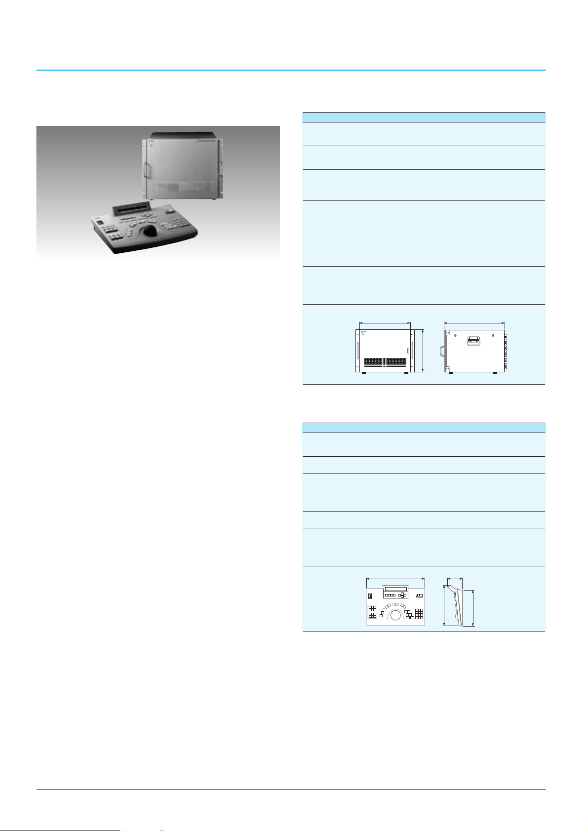
60
SYSTEM CONTROLLER
System Controller
CSP-5000E
*
CSP-5000E (System Controller)
Video
Video inputs:
8 to 128 (max. 16 input boards) (BNC type x 128)
Video outputs: 8 to 32 (max. 4 output boards) (BNC type x 32)
Control ports
Receiver interface: RS-485 (8-pin modular twisted pair x 1)
Keyboard interface: RS-422 (8-pin modular x 7)
Alarm
Inputs: 256 inputs (50-pin, female x 8)
4 inputs x 128 Telemetry receiver (RS-485)
Outputs: 32 (50-pin, female x 1)
Programming
Sequence steps: 128 steps per monitor
Switching dwell time: 1 to 30 seconds, external trigger
Tour sequences: 8
Time events: 8 steps per day
Event programs: 8 types (day of week, calendar date)
Alarm duration: 1 to 120 seconds
Alarm events: Up to 512
Camera IDs: Up to 12 alphanumeric characters
General
Power requirements: AC 220 to 240 V, 50 Hz
Power consumption: Less than 300 W (fully configured)
Operating temperature: 0°C to 40°C
Mass: 32.5 kg (fully configured)
Dimensions:
Specifications
Optional Accessories
CSPB-510VC Input Board
Input: 8 per input board
Video level: 1.0 Vp-p composite, 75 Ω
Cable compensation:Built-in, up to 1,200 m on
RG-6A/U (5C-2V)
CSPB-520VC Output Board
Outputs: 8 per output board
Video level: 1.0 Vp-p composite, 75 Ω
CSPK-5000E (System Keyboard)
Video
Input: 1.0 Vp-p composite, 75 Ω (BNC type x 1)
Output: 1.0 Vp-p composite, 75 Ω (BNC type x 1)
Control ports
Keyboard interface: RS-422 (8-pin modular x 1)
Functions and keys
Camera switching: Numeric keypad, camera key, monitor key
P/T control: Pan (right/left), Tilt (up/down) using joyball
Lens control:
Zoom (tel/wide), Focus (near/far), Iris (open/close)
Camera and enclosure: Camera power on/off, wiper, AUX key x 3
Display LCD displaying selected camera number,
monitor, tour number
General
Power requirements: AC 220 to 240 V, 50 Hz
Power consumption: Less than 3 W
Operating temperature: 0°C to 40°C
Mass: 3.5 kg
Dimensions:
*This model is available only in Europe. For details, please contact your nearest Sony office.
•Up to 128 inputs and 32 outputs matrix switcher
•
Flexible modular configuration for easy system expansion
•Versatile switching patterns of cameras are
programmable
- Up to 128 steps of switching for each monitor
- Up to 8 tours (= sequence mode) are programmable
- Each tour automatically changes according to
time/date schedule
•Easy control of camera pan/tilt and zoom lens thanks to
ergonomic keyboard and joyball
•
Preset capability of camera pan/tilt and zoom lens position
•
RS-422 ports for up to 7 keyboards, for multiple operators
•System partitioning capability for efficient management
•Password protection
•256 alarm inputs and flexible alarm activation
•Twisted pair connection to each telemetry receiver
354 (14)
(8U)
424 (16 3/4) 495 (19 5/8)
424 (16 3/4)
98 (3 7/8)
)
4
/
1
310 (12
)
8
/
3
288 (11
Page 57
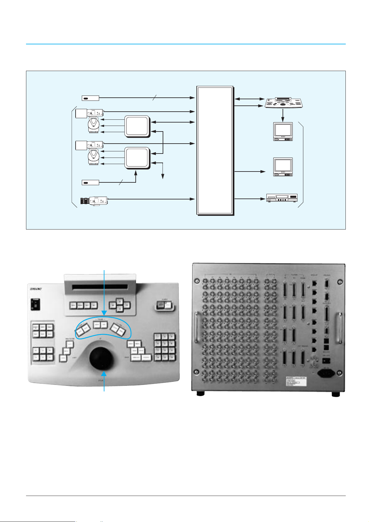
61
SYSTEM CONTROLLER
CPS-5000E Typical System
CSPK-5000E Front Panel CSP-5000E Rear Panel
Lens Control Key
Joyball for Pan/Tilt Control
Alarm sensor
Digital
P/T
Lens
Others
Video
Input
Max.128
Digital
P/T
Lens
Others
Alarm sensor
Digital
4
Alarm input
Camera input
Telemetry
Receiver
Telemetry
Receiver
Camera input
256
Telemetry T/P
RS-485
Next Receiver
RS-485
System
Controller
CSP-5000E
RS-422
Video out
Video out
Video out
Keyboard
CSPK-5000E
Keyboard Monitor
Monitor
Time lapse VCR
Video
output
Max.32
Page 58

62
Page 59
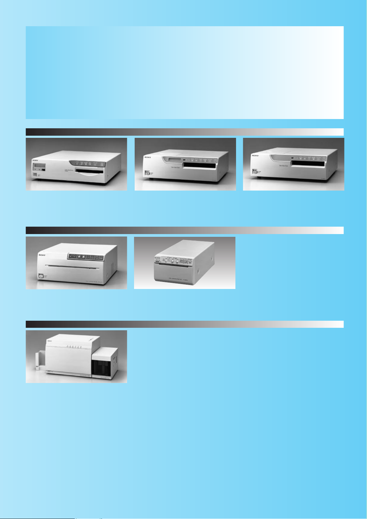
UP-5600MDP
A5 size
300 dpi resolution
UP-2850P/2800P
A6 size
310 dpi resolution
UP-2300P/2100P
A6 size
310 dpi (UP-2300P)
182 dpi (UP-2100P)
Quick Reference
PRINTERS
Sony UP series video printers allow the quick printing of video images in hard copy, making
them especially useful in surveillance applications for identification and archiving.
The range of printers offers copies in color or B/W, in different sizes and with high resolution
and quality. A range of ID card printers are also available. The UP-D6500 provides smart card
recording and both the UP-D6400 and UP-D6500 provide magnetic stripe recording.
63
UP-960CE
190 x 142 mm or 181 x 243 mm picture size
UP-890CE
90 x 68 mm picture size
UP-D6500/D6400/D6300
Digital ID card printer
300 dpi resolution
Magnetic stripe encoding (UP-D6500/D6400)
Smart card encoding (UP-D6500)
Colour Video Printers
Digital Colour Printer
Black & White Video Graphic Printers
Page 60
64
Models UP-5600MDP
Specifications (PAL/NTSC)
UP-2850P UP-2800P UP-2300P UP-2100P
Printing method Dye transfer sublimation thermal printing
Picture size (mm)
Max. 165.1 x 124.8
Max. 176.1 x 132.1 (Digital printing
Max. 110 x 88
with optional UPK-5500 and
UPC-5502SC)
Picture elements (dots)
Max. 1920 x 1176
Max. 2048 x 1536 (Digital printing
Max. 976 x 860 Max. 720 x 564
with optional UPK-5500 and
UPC-5502SC)
Gradations 256 levels process (Yellow, Magenta, Cyan)
Over 16 million colours per dot
Frame memory
4 frame memories
8 frame memories (with optional
4 frame memories 1 frame memory
UPK-5500)
Printing time (seconds) 34 35 60
Input signals RGB (BNC),
Y/C (D-sub 4-pin),
Y/C (D-sub 4-pin),
Composite video (BNC)
Composite video (BNC)
Output signals RGB (BNC),
Y/C (D-sub 4-pin),
Y/C (D-sub 4-pin),
Composite video (BNC)
Composite video (BNC)
Video signal
CCIR/PAL or EIA/NTSC standard
CCIR/PAL standard
Multiple Print Mode
2/4/8/16 split, 2/4/8/16 duplicate, 2/2H/4/16 split, 4/16 duplicate, 2H/4/16 split, 4/16 duplicate, 2H/4/16 split, 4/16 duplicate,
2/4/8/16 strobe, Caption setting Sticker prints, Caption setting Sticker prints, Caption setting Caption setting
Aspect ratio 4 : 3
Monochrome Video Graphic Printers
Models UP-960CE UP-890CE
Specifications (CCIR/EIA) (CCIR/EIA)
Printing method Direct thermal printing
Picture size (mm)
Max. 190 x 142 Max. 100 x 74
(aspect ratio 4:3, CCIR)
Picture elements (dots)
––– Max. 1024 x 608
(CCIR)
Gradations 256 grey levels 256 grey levels (quasi)
Frame memory 1 frame memor y
Printing time (seconds) 12 4
Input signals Composite video (BNC)
Output signals Composite video (BNC)
Video signal CCIR/EIA standard
Print modes
Negative, Reverse, Side, Negative, Reverse, Side, Zoom,
Wide scan, mirror Wide scan, mirror
Aspect ratio 1 : 1 / 4 : 3
Colour Video Printers
FEATURE COMPARISON CHARTS
Page 61
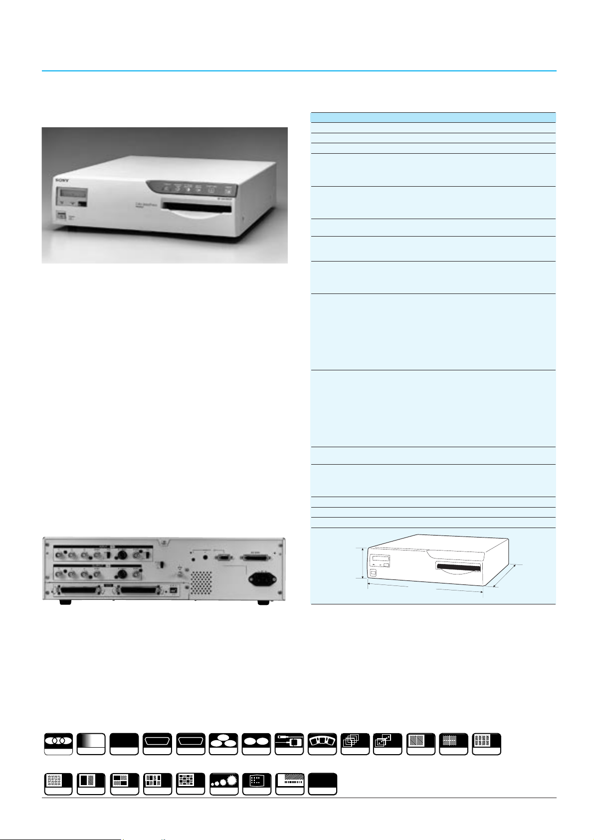
65
Colour Video Printer
UP-5600MDP
•Four frame memories capability or eight frame
memories capability with the optional UPK-5500
•High quality pictures: high resolution of 300 dpi,
1920 (H) x 1176 (V) dots in PAL full print mode
•8 bit/256 gradations in yellow, magenta and cyan
•A5 size (210 x 148 mm / 8 3/8 x 5 7/8 inches) print in
approx. 34 seconds
•Easy-to-use operation menu displayed in the unit’s LCD
panel or a monitor
•Wireless or wired remote control operations with the
optional RM-5500
•RS-232C port for external remote control from PCs
•Accepts both CCIR/PAL and EIA/NTSC signals
•Digital printing is possible with the optional UPK-5500
and SCSI interface board UPK-5502SC which includes
the A/D and D/A conversion
•Multiple video inputs of RGB, Y/C and composite video
signals
•Versatile print modes
•Picture-in-picture function
•Alarm display for easy maintenance
Rear Panel with UPK-5502SC
Supplied Accessories
Ink ribbon holder (1)
Colour printing pack (for 20 prints) (1)
Paper tray (1)
Paper cover (1)
AC power cable (1)
Operation manual (1)
Specifications
UP-5600MDP
Printing method: Dye transfer sublimation thermal printing
Thermal head: 2048 elements (300 dpi)
Printing paper size: A5 size, 210 x 148 mm (8 3/8 x 5 7/8 inches)
Picture size:
165.1 x 124.8 mm (6 1/2 x 5 inches) - PAL, Full Print Mode
165.1 x 125.8 mm (6 1/2 x 5 inches) - NTSC, Full Print Mode
176.1 x 132.1 mm (7 x 5 1/4 inches) - Digital Printing (with
optional UPK-5500 and UPK-5502SC)
Picture elements:
1920 (H) x 1176 (V) dots - PAL, Full Print Mode
1920 (H) x 976 (V) dots - NTSC, Full Print Mode
2048 (H) x 1536 (V) dots - Digital Printing (with optional
UPK-5500 and UPK-5502SC)
Gradations: 256 levels process (Yellow, Magenta, Cyan)
over 16 million colours per dot
Picture memory: 4 frame memories, 2048 x 1024 x 8 bits x 3
8 frame memories with optional UPK-5500,
2048 x 2048 x 8 bits x 3
Printing time:
Approx. 34s - PAL, Full size Print Mode
Approx. 30s - NTSC, Full size Print Mode
Approx. 38s - Digital Printing (with optional UPK-5500 and
UPK-5502SC)
Input terminals:
625 or 525 RGB analogue* (BNC x 4, R/G/B/Sync)
RGB: 0.7 Vp-p, 75 Ω, unbalanced
Sync: 0.3 to 4.0 Vp-p, sync negative, 75 Ω, unbalanced
S-Video (Y/C Separate, 4-pin S terminal)
CCIR/PAL or EIA/NTSC**
Y: 1.0 Vp-p, sync negative, 75 Ω, unbalanced
C: 0.3 Vp-p, 75 Ω, unbalanced
Composite video (BNC)
CCIR/PAL or EIA/NTSC** 1.0 Vp-p, sync negative, 75 Ω
unbalanced
Output terminals:
625 or 525 RGB analogue* (BNC x 4, R/G/B/Sync)
RGB: 0.7 Vp-p, 75 Ω, unbalanced
Sync: 1.0 Vp-p, sync negative, 75 Ω, unbalanced
S-Video (Y/C Separate, 4-pin S terminal)
CCIR/PAL or EIA/NTSC**
Y: 1.0 Vp-p, sync negative, 75 Ω, unbalanced
C: 0.3 Vp-p, 75 Ω, unbalanced
Composite video (BNC)
CCIR/PAL or EIA/NTSC** 1.0 Vp-p, sync negative, 75 Ω,
unbalanced
Interface: With optional UPK-5502SC, SCSI 1 channel,
50-pin amphenol (2)
Control terminals:
Remote control jack (Special mini) for optional RM-5500
Foot switch-1 (stereo mini) for optional FS-20/RM-91
Foot switch-2 (D-sub 9-pin) for optional FS-30
RS-232C interface port (D-sub 25-pin)
Power requirements: AC 220 to 240 V, 50/60 Hz
Power consumption: Max. 1.2 A
Mass: 14 kg (30 lb 14 oz)
Dimensions:
Unit: mm (inches)
* The UP-5600MDP can accept sync-on-G or external sync automatically.
** CCIR/PAL or EIA/NTSC signals are selected using the input selector on the unit’s rear panel.
Optional Accessories
Four Frame Memory Board UPK-5500
Digital Interface Board UPK-5502SC
Wired/Wireless Remote Commander RM-5500
Remote Control Unit RM-91
Foot Switch FS-30, Foot Switch FS-20
Colour Printing Pack UPC-5510*/5UPC-5510*/UPC-5510C
Cassette for UPC-5510/5UPC-5510 UPA-5500
*The UPC-5510/5UPC-5510 are not supplied with a cassette.
with UPK-5500
COLOUR VIDEO PRINTERS
R
Y C
S-VIDEO
MENU
RM-91 & FS-20
CAPTION
COLOUR
16
16 DUPLICA TE
256
GRADATIONS
2
2
SPLIT
A 5
210 x 14 8
4
SPLIT
4
CONTROL
RS-232C
8
8
SPLIT
IMAGE
SCSI
16
16 SPLIT
G B
R.G.B.
STROBE
124
424 (16
(5)
3
/
4
)
)
4
/
3
475 (18
FS-30
COLOUR
ADJUST
MEMORY
4
4 MEMORIES
8
8 MEMORIES
2
2 DUPLICA TE
4
4 DUPLICATE
8
8 DUPLICA TE
Page 62

66
COLOUR VIDEO PRINTERS
Colour Video Printer
UP-2850P/2800P
•UP-2850P: four frame memories,
UP-2800P: one frame memory
•
High quality pictures: high resolution of 310 dpi,
860 (H) x 976 (V) dots in normal mode
•8 bit/256 gradations in yellow, magenta and cyan
•Near A6 size print (130 x 88 mm/5 1/8 x 3 1/2 inches) in
approx. 35 seconds
•Easy-to-use operation menu displayed on the built-in
LCD or the connected monitor
•Wireless or wired remote control operations
•Multiple video inputs of RGB, Y/C and composite
CCIR/PAL video signals
•Versatile print modes
Supplied Accessories
Colour printing pack (for 10 prints) (1)
Paper tray (1)
Paper cover (1)
AC power cable (1)
Operation manual (1)
Specifications
UP-2850P/2800P
Printing method: Dye transfer sublimation thermal printing
Thermal head: 1024 elements (12.2 dots/mm)
Printing paper size: 130 x 88 mm (5 1/8 x 3 1/2 inches)
Picture size: Max. 110 x 80 mm (4 3/8 x 3 1/4 inches)
Picture elements: Max. 860 (H) x 976 (V) dots
Gradations: 256 levels process (Yellow, Magenta, Cyan)
over 16 million colours per dot
Picture memory: UP-2850P: Four frame memories
UP-2800P: One frame memory
Printing time: Approx. 35 seconds
Input terminals:
RGB analogue (BNC x 4, R,G,B, Sync)
RGB: 0.7 Vp-p, 75 Ω, unbalanced
Sync: 0.2 to 4.0 Vp-p, negative, 75 Ω, unbalanced
Y/C separate (4-pin S terminal)
Y: 1.0 Vp-p, sync negative, 75 Ω, unbalanced
C: 0.3 Vp-p, 75 Ω, unbalanced
Composite video (BNC)
CCIR/PAL:1.0 Vp-p, sync negative, 75 Ω, unbalanced
Output terminals: RGB analogue (BNC x 4, R, G, B, Sync)
RGB: 0.7 Vp-p, 75 Ω, unbalanced
Sync: 1.0 Vp-p, negative, 75 Ω, unbalanced
Y/C separate (4-pin S terminal)
Y: 1.0 Vp-p, sync negative, 75 Ω, unbalanced
C: 0.3 Vp-p, 75 Ω, unbalanced
Composite video (BNC)
CCIR/PAL:1.0 Vp-p, sync negative, 75 Ω, unbalanced
Control terminals:
Control (for the optional foot switch FS-36/20 and
remote control unit RM-91): stereo mini jack
Control (for the supplied remote control unit):
special mini jack
RS-232C interface port (D-sub 25-pin)
Power requirements: AC 220 to 240 V, 50/60 Hz
Power consumption: Max. 1.0 A
Mass: Approx. 10.5 kg (23 lb 2 oz)
Dimensions:
Unit: mm (inches)
Optional Accessories
Wired/Wireless Remote Commander RM-5500
Remote Control Unit RM-91
Foot Switch FS-36
Foot Switch FS-20
Colour Printing Pack UPC-2010 (for 200 prints)
Black and White Printing Pack UPC-2020 (for 200 prints)
Colour Postcard Printing Pack UPC-2070E (for 150 prints)
Self-adhesive Colour Printing Pack UPC-20S01 (for 200 prints)
16-split Self-adhesive Pre-cut Color Printing Pack
UPC-20S16 (for 200 prints)
4-split Self-adhesive Pre-cut Color Printing Pack
UPC-20S04 (for 200 prints)
Paper Ejector UPA-2001
Paper Tray for UPC-2070E: UPA-2002
2H
SPLIT
2
H
POSTCARD
STICKER
Rear Panel
R
G B
R.G.B.
COLOUR
256
GRADATIONS
A6
130x88
CONTROL
RS-232C
Y C
S-VIDEO
RM-91 & FS-20
FS-36
125 (5)
370 (14
5
/
)
8
)
2
/
1
417 (16
4
4 MEMORIES
4
4 DUPLICATE
16
16 DUPLICA TE
2
SPLIT
2
4
SPLIT
4
16
16 SPLIT
IPP
STROBE
MENU
CAPTION
200
200 FEED
COLOUR
ADJUST
MEMORY
Page 63
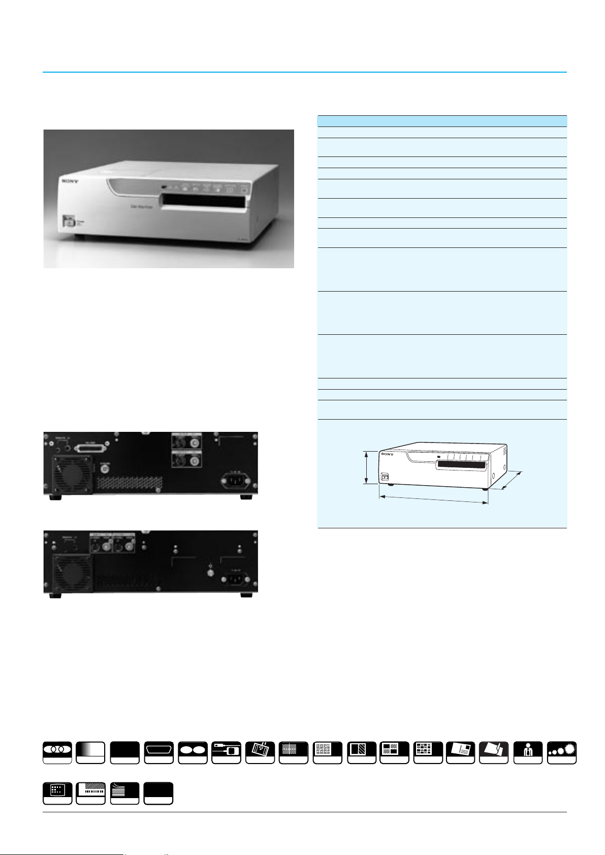
67
COLOUR VIDEO PRINTERS
Colour Video Printer
UP-2300P/2100P
•One frame memory capability
•
UP-2300P: 310 dpi resolution
UP-2100P: 182 dpi resolution
•8 bit/256 gradations in yellow, magenta and cyan
•Near A6 size print (130 x 88/5 1/8 x 3 1/2 inches) in
approx. 35 seconds (UP-2300P) or 60 seconds
(UP-2100P)
•Easy-to-use operation menu displayed on the monitor
•Wireless or wired remote control operations
•Multiple video inputs of Y/C and composite CCIR/PAL
video signals
•Versatile print modes
UP-2300P Rear Panel
Supplied Accessories
Colour printing pack (for 10 prints) (1)
Paper tray (1)
Paper cover (1)
AC power cable (1)
Operation manual (1)
Specifications
UP-2300P/2100P
Printing method: Dye transfer sublimation thermal printing
Thermal head: UP-2300P: 1024 elements (12.2 dots/mm)
UP-2100P: 608 elements (7.2 dots/mm)
Printing paper size: 130 x 88 mm (5 1/8 x 3 1/2 inches)
Picture size: 110 x 80 mm (4 3/8 x 3 1/4 inches)
Picture elements: UP-2300P: 860 (H) X 976 (V) dots
UP-2100P: 720 (H) X 564 (V) dots
Gradations: 256 levels process (Yellow, Magenta, Cyan)
over 16 million colours per dot
Picture memory: One frame memory
Printing time: UP-2300P: 35 seconds
UP-2100P: 60 seconds
Input terminals:
Y/C separate (4-pin S terminal)
Y: 1.0 Vp-p, sync negative, 75 Ω, unbalanced
C: 0.3 Vp-p, 75 Ω, unbalanced
Composite video (BNC), Phono
CCIR/PAL:1.0 Vp-p, sync negative, 75 Ω, unbalanced
Output terminals:
Y/C separate (4-pin S terminal)
Y: 1.0 Vp-p, sync negative, 75 Ω, unbalanced
C: 0.3 Vp-p, 75 Ω, unbalanced
Composite video (BNC)
CCIR/PAL:1.0 Vp-p, sync negative, 75 Ω, unbalanced
Control terminals: Control (for the optional foot switch FS-36/20):
stereo mini jack
Control (for the supplied remote control unit):
special mini jack
RS-232C interface port (D-sub 25-pin)*
Power requirements: AC 220 to 240 V, 50/60 Hz
Power consumption: Max. 1.0 A
Mass: UP-2300P: 10 kg (22 lb 1 oz)
UP-2100P: 9 kg (19 lb 13 oz)
Dimensions:
Unit: mm (inches)
Optional Accessories
Wired/Wireless Remote Commander RM-5500
Remote Control Unit RM-91
Foot Switch FS-36
Foot Switch FS-20
Colour Printing Pack UPC-2010 (for 200 prints)
Black and White Printing Pack UPC-2020* (for 200 prints)
Colour Postcard Printing Pack UPC-2070E* (for 150 prints)
Self-adhesive Colour Printing Pack UPC-20S01 (for 200 prints)
16-split Self-adhesive Pre-cut Color Printing Pack
UPC-20S16* (for 200 prints)
4-split Self-adhesive Pre-cut Color Printing Pack
UPC-20S04* (for 200 prints)
Paper Ejector UPA-2001*
Paper Tray for UPC-2070E: UPA-2002*
* UP-2300P ONLY
UP-2100P Rear Panel
UP-2300P
UP-2300P UP-2300PUP-2300PUP-2300P
2H
SPLIT
2
H
POSTCARD
STICKER
Y C
S-VIDEO
COLOUR
256
GRADATIONS
A6
130x88
CONTROL
RS-232C
RM-91 & FS-20
FS-36
4
4 DUPLICATE
125 (5)
370 (14
5
/
)
8
)
2
/
1
417 (16
IPP
STROBE
16
16 DUPLICA TE
4
SPLIT
4
16
16 SPLIT
MENU
CAPTION
200
200 FEED
COLOUR
ADJUST
MEMORY
Page 64

68
B/W Video Graphic Printer
UP-960CE
•Thermal video graphic printer with 256 steps of
gradation grey level
•
Large print size of 190 x 142 mm in standard mode
•High speed printing (approx. 12 seconds)
•Frame/Field memory selectable
•Printing direction selectable: Standard/Side/Reverse
•Positive/Negative printing
•Normal/Wide scan selectable
•4:3/1:1 aspect ratio selectable
•CCIR/EIA automatic selection
•Multiple copy function by pressing the “COPY” button
Rear Panel
Supplied Accessories
AC power cord (1)
Printing Paper Roll (UPP-210HD) (1)
Head cleaning sheet (1)
BNC cable (1.5m) (1)
Operation manual (1)
Optional Accessories
Foot Switch FS-20
High Density Printing Paper Roll UPP-210HD
Normal Density Printing Paper Roll UPP-210SE
Remote Control Unit RM-91
Specifications
UP-960CE
Printing method: Direct thermal printing
Thermal head: 1280 elements
Picture size:
(CCIR)
Standard mode: 190 x 142 mm (7 1/2 x 5 5/8 inches)
Side mode: 181 x 243 mm (7
1
/4 x 9 5/8 inches)
(EIA)
Standard mode: 190 x 144 mm (7 1/2 x 5 3/4 inches)
Side mode: 184 x 243 mm (7 1/4 x 9 5/8 inches)
Gradations: 256 grey levels
Picture memory: 2048 x 1024 x 8 bit
Printing time: Approx. 12 seconds/screen
(at aspect ratio 4:3)
Input terminal:
VIDEO IN (BNC), CCIR/EIA Composite video signal
1.0 Vp-p, 75 Ω/high impedance (switchable)
Output terminal: VIDEO OUT (BNC) Loop through
Control terminal:
REMOTE (for the optional FS-20 foot switch or RM-91
remote control unit): Stereo mini jack
Power requirements: AC 220 to 240 V, 120 V, 50/60 Hz
Power consumption: 220 to 240 V: 1.3 A, 120 V: 2.4 A
Mass: Approx. 8 kg (17 lb 10 oz)
Dimensions:
Unit: mm (inches)
MONOCHROME VIDEO GRAPHIC PRINTERS
)
4
/
1
132 (5
316 (12
1
/
2
)
1
305 (12
)
8
/
256
GRADATIONS
210
210 mm
RM-91 & FS-20
SMALL
P P
NEGATIVE
P
REVERSE
S I DE
P
P
MIRROR
P
WIDE
1:1
EASY LOAD
Page 65
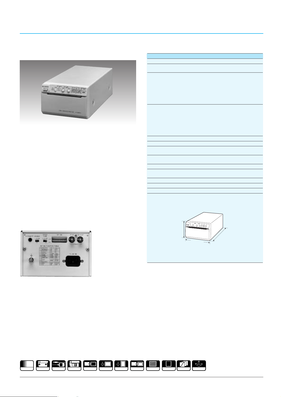
69
MONOCHROME VIDEO GRAPHIC PRINTERS
B/W Video Graphic Printer
UP-890CE
Specifications
•Thermal video graphic printer with quasi 256 steps of
gradation grey level
•Small size and light weight body
•A fast printing speed of approx. four seconds
•High resolution printing of 1024 x 608 dots
(in Wide 2 scan mode)
•
Wide scanning function (Normal/Wide 1/Wide 2 selectable)
•Multiple copy function
•Economy print mode offers maximum 270 prints from
one paper roll (230 prints in normal print mode)
•Frame/Field memory selectable
•4:3/1:1 aspect ratio selectable
•Positive/negative printing
•Standard/side print mode selectable
•Normal/reverse direction printing
•CCIR/EIA automatic selection
Rear Panel
Supplied Accessories
AC power cord (1)
Printing Paper Roll (UPP-110HA) (1)
Head cleaning sheet (1)
BNC-BNC connecting cable (1.5m) (1)
Operation manual (1)
UP-890CE
Printing method: Direct thermal printing
Thermal head: Thin-film thermal head (with built-in drive IC)
1024-dot drive
Picture size : (CCIR)
(Standard print mode, Normal size: 90 x 68 mm (3
5
/8 x 2 3/4 inches)
at aspect ratio 4:3) Wide 1 size: 95 x 71 mm (3
3
/4 x 2 7/8 inches)
Wide 2 size: 100 x 74 mm (4 x 3 inches)
(EIA)
Normal size: 90 x 69 mm (3
5
/8 x 2 3/4 inches)
Wide 1 size: 95 x 72 mm (3
3
/4 x 2 7/8 inches)
Wide 2 size: 100 x 74 mm (4 x 3 inches)
Picture elements: (CCIR)
Normal size: 922 (H) x 560 (V) dots
Wide 1 size: 970 (H) x 582 (V) dots
Wide 2 size: 1024 (H) x 608 (V) dots
(EIA)
Normal size: 922 (H) x 472 (V) dots
Wide 1 size: 970 (H) x 490 (V) dots
Wide 2 size: 1024 (H) x 508 (V) dots
Gradations: 256 grey levels (quasi)
Picture memory: 6 bits frame memory (1024 x 768 x 6 bits)
Printing time: 4 seconds/screen - Standard print mode
(at aspect ratio 4:3) 7 seconds/screen - Side print mode
Input terminal:
VIDEO IN (BNC), CCIR/EIA Composite video signal
1.0 Vp-p, 75 Ω/high impedance (switchable)
Output terminal:
VIDEO OUT (BNC) Loop through or E.E switchable
Control terminal: REMOTE (for the optional FS-20 foot switch or
RM-91 remote control unit): Stereo mini jack
Power requirements: AC 220 to 240 V, 50/60 Hz
Power consumption: Max. 0.8 A
Mass: Approx. 3.5 kg (7 lb 11 oz)
Dimensions:
Unit: mm (inches)
Optional Accessories
High Quality Printing Paper (Type I) UPP-110S
High Density Printing Paper (Type II) UPP-110HD
Superior Density Printing Paper (Type III) UPP-110HA
Foot Switch FS-20
Remote Control Unit RM-91
256
GRADATIONS
110
110 mm
RM-91 & FS-20
SMALL
P P
NEGATIVE
P
REVERSE
S I DE
P
P
MIRROR
/4
1
106 (4
154 (6
)
1
/
8
)
303 (12)
P
WIDE
1:1
3
GAMMA
EASY LOAD
Page 66
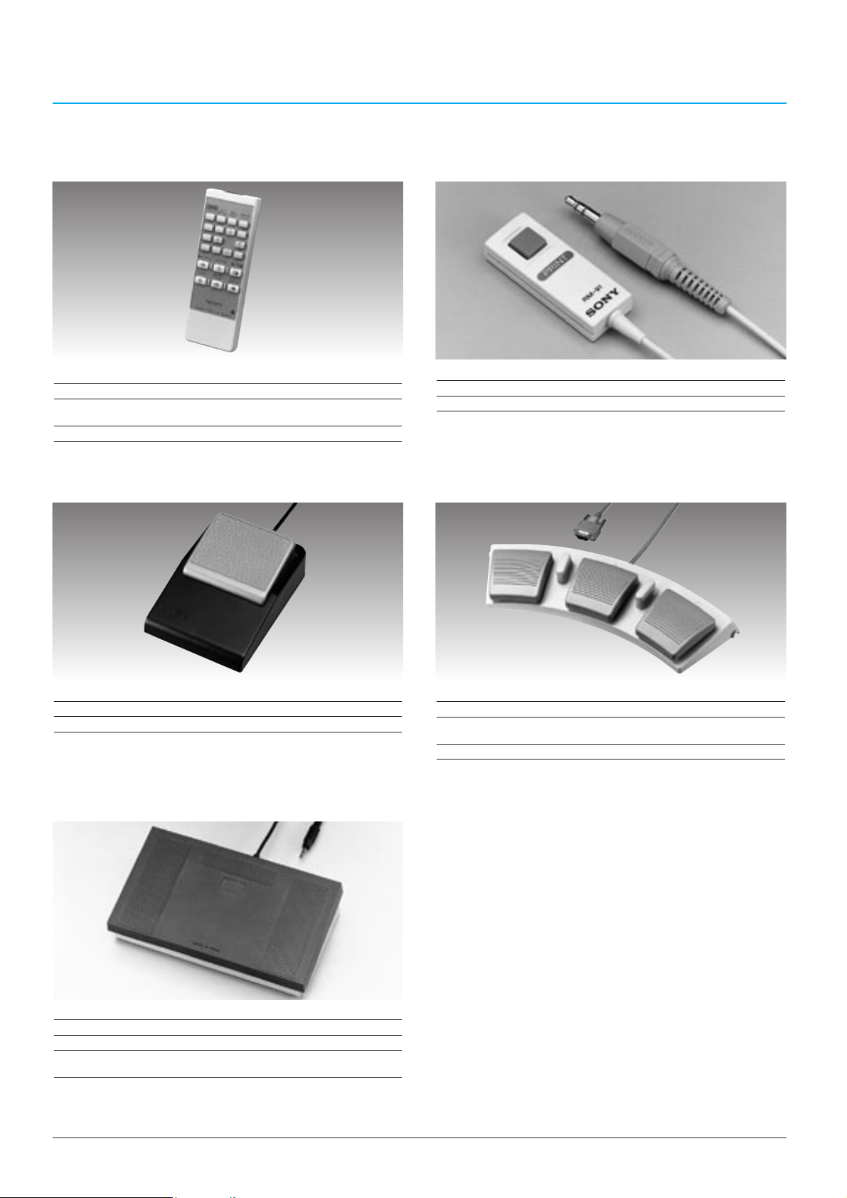
70
Wired/Wireless Remote Commander
RM-5500
Specifications
Power requirement: DC 3 V
Dimensions: 62 (W) x 20 (H) x 175 (L) mm
(2 1/2 x27/32 x 7 inches)
Mass: 95 g (3 oz)
Remote Control Unit
RM-91
(for UP-5600MDP/2850P/2800P/2300P/
2100P/960CE/890CE)
(for UP-5600MDP/2850P/2800P/
2300P/ 2100P)
Specifications
Connector: Stereo mini
Cable length: 5 m
Specifications
Terminal: D-sub 9-pin
Dimensions: 337.3 (W) x 46.1 (H) x 128.0 (D) mm
(13 3/8 x 1 7/8 x 5 1/8 inches)
Mass: 900 g (1 lb 15 oz)
Specifications
Connector: Stereo mini
Cable length: 5 m
Foot Switch
FS-30 (for UP-5600MDP)
Specifications
Terminal: Stereo mini
Cable length: 5 m
Dimensions: 175 (W) x 53 (H) x 105 (D) mm
(7 x 2 1/8 x 4 1/4 inches)
Foot Switch
FS-36 (for UP-2850P/2800P/2300P/2100P)
Foot Switch
FS-20
(for UP-5600MDP/2850P/2800P/2300P/
2100P/960CE/890CE)
VIDEO PRINTER OPTIONAL ACCESSORIES
Page 67
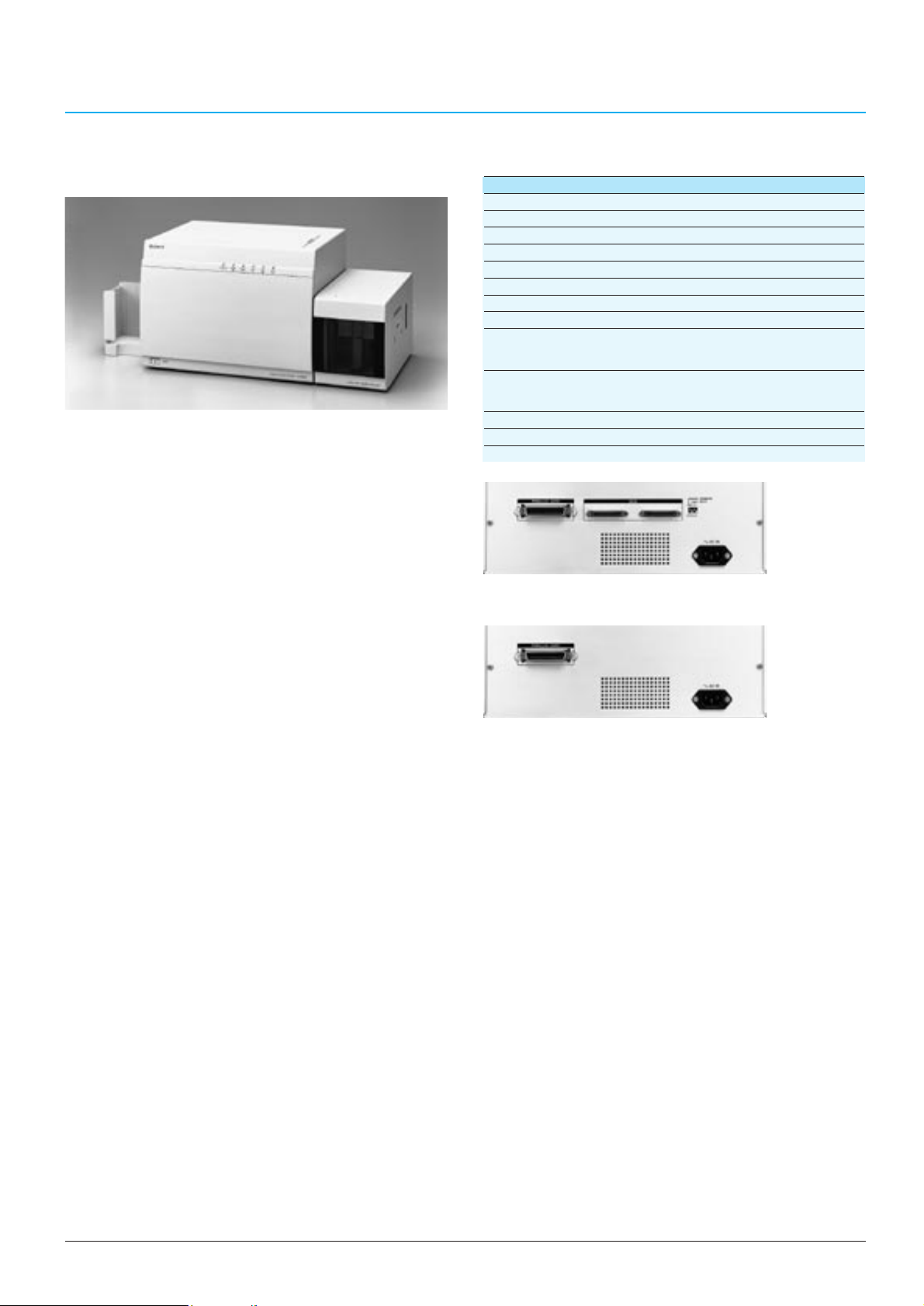
71
Supplied Accessories
Floppy Disk (1)
AC Power Cable (1)
Card Tray (1)
Operational Manual (1)
Ink Ribbon Holder (1)
Cleaning Roller Holder Set (1)
Optional Accessories
Colour Ink Ribbon (YMCL) 5UPR-6040 (250 prints x 5 rolls)
Colour Ink Ribbon (YMCKL) 5UPR-6080 (200 prints x 5 rolls)
Black and White Ribbon (K) UPR-6025 (1000 prints x 1 roll)
Auto Card Stacker UPA-6002
Auto Card Feeder UPA-6003
Thermal Head UPU-D65H
Digital Colour Printer
UP-D6500/D6400/D6300
•High resolution of 300 dpi and over 16 million colours
reproduction
•High speed YMC print and thermal lamination
process - 45 seconds in 256 gradations (YCML, SCSI)
•Dual-side printing (ISO 7810 Standard Card)
•Acceptable card thickness is from 0.3 mm to 1.5 mm
•Magnetic stripe encoding (UP-D6500/D6400)
•Smart card encoding (UP-D6500)*
•SCSI-2 interface for high volume applications
(UP-D6500)
•IEEE 1284 interface for easy setup
•Holds up to 125 cards (UP-D6500: Max. 250 cards)
•Template memory function for quick data download
(UP-D6500/D6400)*
•Anti-forgery security lamination*
•Compatibility with Windows®95/98 and Windows NT
®
OS
*Separate software necessary
UP-D6500 with the optional UPA-6003 Auto Card Feeder
UP-D6500/D6400/D6300
Printing Method: Dye transfer sublimation thermal printing
Resolution: 300 dpi
Acceptable Card Length: 85.47 to 93.00 mm (3 3/8 X 3 21/32 inches)
Acceptable Card Height: 53.92 to 60.00 mm (2 1/8 X 2 11/32 inches)
Acceptable Card Thickness:
0.3 to 1.5 mm (12 X 59 mils)
Card Holder Capacity: 125 cards (UP-D6500: Max. 250 cards)
Printing Time: Approx. 45 seconds (YCML, SCSI)
Interface: SCSI-2 (UP-D6500 only), IEEE standard 1284
Card Supply: 125 cards with the optional UPA-6003 Auto Card
Feeder (UP-D6500: 250 cards when using two of
the optional UPA-6003 Auto Card Feeder)
Card Stack: 125 cards with the supplied card tray
(UP-D6500: Max. 250 cards with the optional
UPA-6002 Auto Card Stacker)
Power Requirements: AC 220 to 240 V
Mass: 11.5 kg (25 lb 6 oz)
Dimensions:
350 x 260 x 257 mm (13 7/8 x 10 1/4 x 10 1/8 inches)
Specifications
UP-D6500 Rear Panel
UP-D6400/D6300 Rear Panel
DIGITAL COLOUR PRINTER
Page 68

72
Page 69
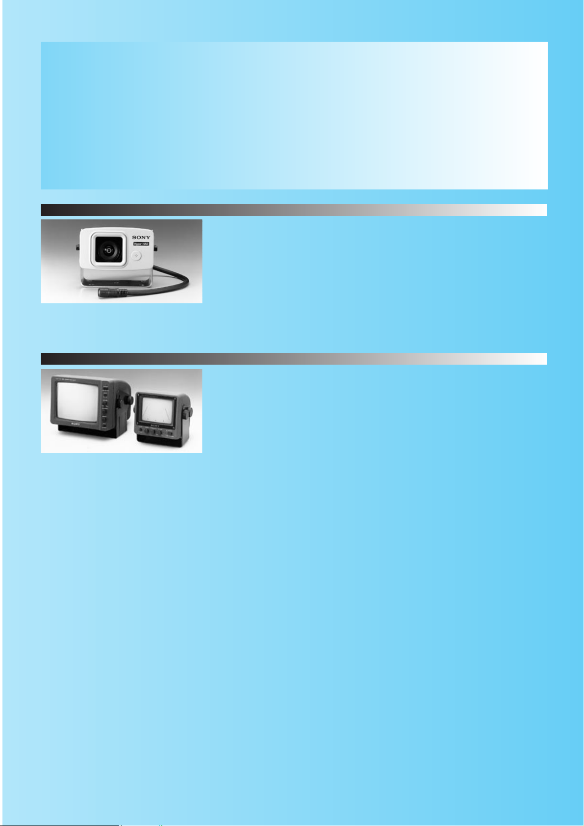
SSC-534AM
Exterior camera for vehicles
Quick Reference
AUTOMOTIVE CAMERA AND
MONITORS
The combination of the SSC-534AM and SSM-504AM/724AMR is an extremely useful and
comprehensive camera/monitor system for diverse mobile applications. This system is ideal
for any vehicle for applications such as monitoring the rear when reversing.
SSM-504AM/724AMR
5-inch monitor (SSM-504AM)
7-inch monitor (SSM-724AM)
B&W Camera
B&W Monitors
73
Page 70
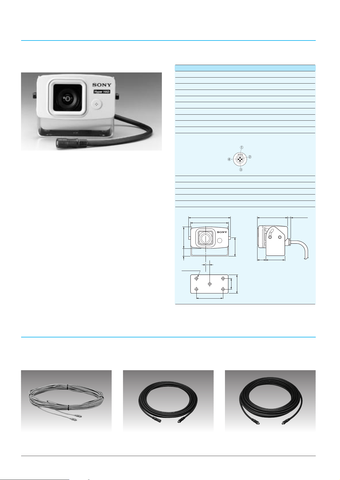
AUTOMOTIVE CAMERAAND MONITOR SYSTEM OPTIONAL ACCESSORIES
74
AUTOMOTIVE CAMERAAND MONITORS
Supplied Accessories
Camera bracket (1)
Rubber cap (1)
Adhesive (1)
Self-fusing tapes (2)
3 mm Allen key (1)
4 mm washers (4)
Angle adjusting screws (4)
5 mm hexagon head bolts (5)
5 mm washers (5)
Rubber nuts (5)
Operation manual (1)
CCD B/W Video Camera
SSC-534AM
•Compact, lightweight and rugged construction
•1/2-inch IT Hyper HAD CCD provides extremely high
sensitivity with a minimum illumination of 0.3 lx
•Wide angle view - a full 100 degrees horizontally,
80 degrees vertically
•Built-in electret condenser microphone
•Only single 4-pin Multiple Cable required between the
SSC-534AM and the SSM-504AM/724AMR to transmit
video and audio signals, together with DC power
SSC-534AM
Image device: 1/2-inch Interline Transfer Hyper HAD CCD
Picture elements: 500 (H) x 582 (V)
Sensing area: 6.3 mm x 4.7 mm
Lens: f = 3.0 mm, F1.6 with auto-iris
Signal system: CCIR standard
Scanning system: 625 lines, 2:1 interlace
Synchronization: Internal
Horizontal resolution: 380 TV lines
Minimum illumination: 0.3 lx
Signal-to-noise ratio: 50 dB (AGC OFF)
Video/audio output:
4-pin Multi-connector (for connection to the SSM-504AM/
724AMR)
1DC input
2Video output: 1.0 Vp-p, 75 Ω,
sync negative
3Ground
4Audio output: -5 dBu
(436 mVrms), less than 10 kΩ,
unbalanced
Power requirements: DC 12 V
Power consumption: 1.2 W (at DC 12 V)
Operating temperature: -20˚C to 70˚C (-4˚F to 158˚F)
Storage temperature: -30˚C to 85˚C (-22˚F to 185˚F)
Mass: 550 g (1 lb 3 oz)
Dimensions:
Unit: mm (inches)
0 dBu = 0.775 Vrms
Specifications
Camera Cable (4-pin)
VK-110A/120A
(10 m/20 m)
• 4-pin Multi (male)
¨
4-pin Multi (male)
Water-resistant Extension Cable (4-pin)
VK-305
(5 m)
• 4-pin Multi (male)
¨
4-pin (female)
Water-resistant Camera Cable (4-pin)
VK-310A/318A/320A
(10 m/18 m/20 m)
• 4-pin Multi (male)
¨
4-pin Multi (male)
105.6 (4 1/4)
94 (3 3/4)
76.5 (3 1/8)
Approx 5 (7/32)
)
4
/
1
55 (2
)
16
/
13
20.5
(
Hole 6.5 (9/32)
10 (13/32)
1
15
)
8
/
27 (1
)
16
/
48 (1
)
/
15
48 (1
21.5
7
46 (1 13/16)
/8)
(
16
66 (2 5/8)
Page 71
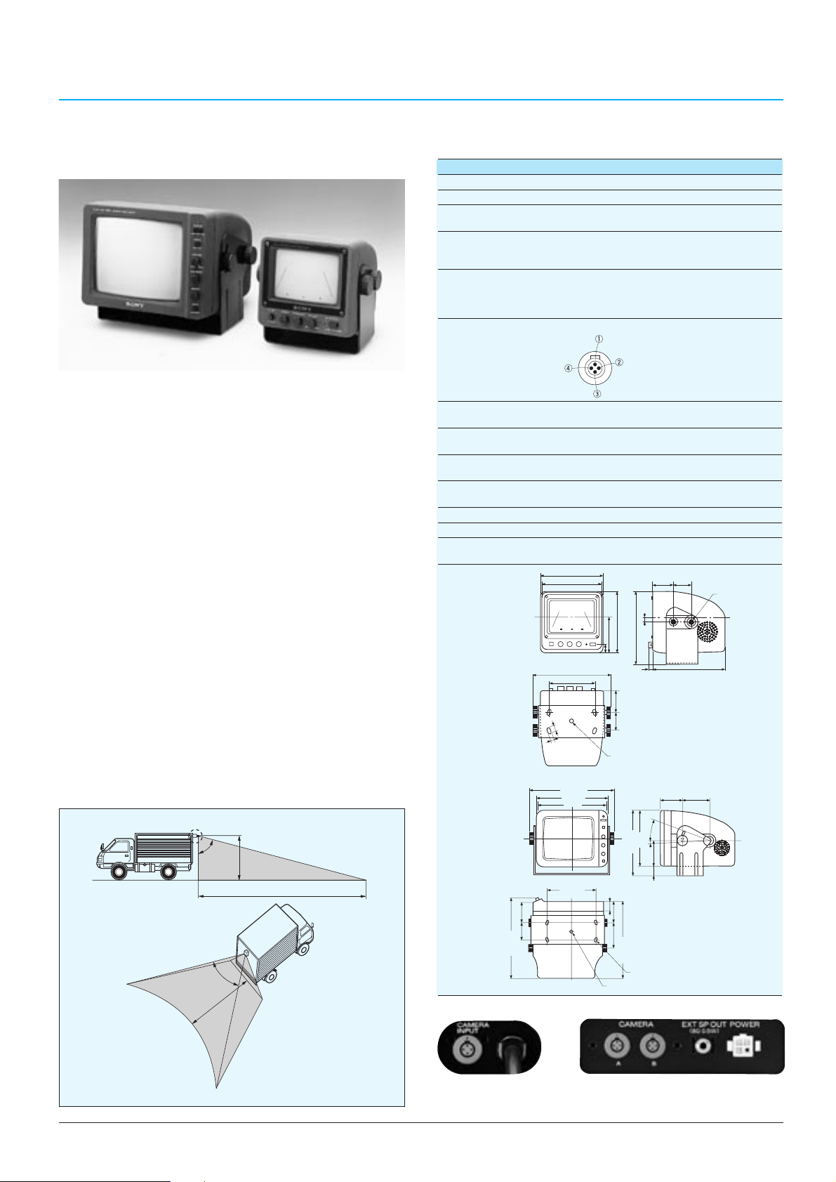
75
AUTOMOTIVE CAMERAAND MONITORS
5-inch/7-inch B/W Monitor
SSM-504AM/724AMR
SSM-724AMR SSM-504AM
•Offers bright, clear and high-contrast pictures
•Semi-flat square/non-glare CRT (SSM-724AMR only)
•Compact, lightweight and rugged construction
•Built-in speaker
•Audio output connection for an optional external
speaker (SSM-724AMR only)
•Day/Night switch adjusts picture brightness for normal
or low-light conditions
•Automatic operation when reversing
•Dual camera inputs (SSM-724AMR only)
•
Alternative power supply mode (DC 12/24V, SSM-724AMR
only)
•Only a single 4-pin Multiple Cable required between the
SSC-534AM and the SSM-504AM/724AMR to transmit
video and audio signals, together with DC power
Supplied Accessories
Mounting bracket (1) Screws (4)
Bolts (4) Washers (12)
Spring washers (8) Nuts (4)
Power supply cable (1 set) Bracket holder (1 set)
Operation manual (1)
Monitor scale (1) (SSM-724AMR only)
Field of View
Specifications
SSM-504AM/724AMR
Video signal system: CCIR standard
Picture tube:
5-inch/7-inch B/W measured diagonally, 90° deflection
Resolution: SSM-504AM: 550 TV lines
SSM-724AMR: 650 TV lines
Power connector: White: Positive 12 V/24 V input
Black: Ground
Green: Reverse gear 12 V/24 V input
Speaker: ø50 mm (2 inches)
Impedance 8 Ω
SSM-504AM: 0.3 W output (max.)
SSM-724AMR: 0.5 W output (max.)
Video/audio input:
4-pin Multi-connector (for connection to the SSC-534AM)
1 DC 12 V output
2 Video input: 1.0 Vp-p, 75 Ω,
sync negative
3 Ground
4
Audio input: -5 dBu (436 mVrms),
more than 30 kΩ, unbalanced
Output:
External speaker jack (mini jack) (SSM-724AMR only)
Impedance 8 Ω
Front controls:
Power, Audio volume, Brightness, Contrast, DAY/NIGHT
select, Camera input select (SSM-724AMR only)
Power requirements: SSM-504AM: DC 12 V
SSM-724AMR: DC 12 V or 24 V
Power consumption: SSM-504AM: 8 W
SSM-724AMR: 23 W
Operating temperature: -15˚C to 60˚C (5˚F to 140˚F)
Storage temperature: -25˚C to 85˚C (-13˚F to 185˚F)
Mass: SSM-504AM: Approx. 1.5 kg (5 lb 8 oz)
SSM-724AMR: Approx. 3.2 kg (7 lb)
Dimensions:
Unit: mm (inches)
0 dBu = 0.775 Vrms
SSM-504AM
SSM-504AM
SSM-724AMR
SSM-724AMR
Rear Panel
80˚
3m
16m
100˚
16m
/8)50 (2)
1
53 (2
/8)
3
235 (9
Hole
6.5 x 12
9
32
/
(
138 (51/2)
136 (53/8)
167.8 (65/6)
100 (4)
)
2
1
/
x
234 (9 1/4)
205 (8
203 (8)
120 (4 3/4)
/8)
1
/8)
130 (5
1
152 (6)
78 (3
/4)
3
19 (
2)
50 (
/8)
5
40 (1
Hole ¿ 7 ( 9/32)
)
1
/8)
/8)
7
151 (6)
174 (6
/4)
1
25 (1)
56 (2
/4)
73.5 (3)
3
220 (8
Hole
6.5 x 14
(9/32 x 9/16)
9
Hole ¿ 7 (
/32)
/32)
11
8 (
10 (13/32)
25°
5°
5
40 (1 )
50 (2)
/8
1
/2)
165 (6
56 (2 1/4)
73.5 (3)
75.5 (3)
/32)
9
23 (
2-MS
Page 72
76
AGC Automatic gain control. Amplifies existing video to help camera reproduce a
video signal at very low light levels.
Analog backlight compensation (BLC)
Picture brightness adjusted automatically depending on lighting conditions.
Overcomes the problem of strong backlight which often causes the subject of
the picture to be cast into shadow.
APC Adaptive picture control. Automatically detects the condition of the recording
head and video cassette tape, then sets the optimum recording head current.
Available on all SVT time lapse VCRs.
Aperture/sharp mode
Makes object outlines in the picture appear sharper. Ideal for situations where
an
object merges into the scene with a similar shade.
Aspherical type lens Lens that allows for a wider viewing area with very little distortion.
ATW Auto tracing white balance. Adjusts the white balance automatically in response
to varying light conditions.
ATWPro Ideal for frequently changing light conditions and applications where the
operator needs to see objects as they appear to the eye. Effective operational
colour range is 2500 to 6000K.
Auto iris Automatically adjusts the iris element as the light level changes.
AWB Auto white balance. Automatically memorizes adjusted white balance values
Backlight compensation See Smart Control (Digital)
See Analog backlight compensation (Analog)
C mount Type of camera mount which measures 17.5 mm from the lens rear mounting
surface to the camera's CCD.
CS mount Type of camera mount which measures 12.5 mm from the lens rear mounting
surface to the camera's CCD. CS mount lenses can be used with C mount
cameras by adding a 5 mm spacer.
DC servo auto iris lens Lens that relies on DC power from the camera to control the iris.
DSP (Digital signal processing) Converts the analog signal from a CCD image sensor into a digital signal
through an internal A/D converter. The signal is then broken down into
luminance and chrominance components for processing, adjustment and feature
enhancement enabling many digital features such as backlight compensation.
Duplex Type of multiplexer allowing simultaneous live monitoring or playback as images
are being recorded.
Exwave HAD CCD HAD sensor with a nearly gap-less OCL (On-chip-lens) located over each pixel
on the CCD resulting in more than twice the sensitivity and 1/50 the smear
compared to the Hyper HAD CCD. Used in SSC-DC50AP/54AP/58AP cameras.
Hybrid recording
Original Sony recording method of the HSR-1P, which uses both a Hard Disk Drive
and DV tape. Images are first recorded to HDD, then transferred to DV tape.
Hyper HAD CCD
HAD sensor with an OCL (On-chip-lens) located over each pixel on the CCD which
helps increase sensitivity and reduce smear. Used in most Sony security cameras.
GLOSSARY
Page 73

73
RealAction recording LP recording mode which allows three times as many frames/s to be recorded in
24 H mode. (SVT-L230P only)
Sensitivity The amount of light falling on a scene measured in lux.
Simplex Type of multiplexer which allows the user to choose between live monitoring,
recording or playback.
Smart Control Digital circuit within the camera providing automatic backlight compensation by
automatically adjusting iris and gain. See DSP also.
Smear Vertical streaks above and below a brightly lit object or light source when
observed on the monitor. Vertical lines on the screen are caused by the leakage
of unwanted light onto the vertical shift register of the CCD.
Synchronization Used in multi-camera installations where automatic switching is employed and
allows roll-free switching from camera to camera.
Trinitron CRT Sony CRT which allows for high resolution and the best possible picture
reproduction. The completely flat, straight vertical surface of the Trinitron CRT
provides very low purity imperfection.
Triple multiplexing Video, sync and power transmitted over a single coaxial cable.
T urbo AGC Powerful automatic gain control function. Increases range of video gain
compared to conventional AGC resulting in greater sensitivity.
Video servo auto iris lens Lens that relies on video input to control the iris opening. When the video level is
high, the lens iris closes. When the video level is low, it opens.
5600K mode White balance mode recommended for outdoor daytime shooting
GLOSSARY
Page 74

74
C
CSP-5000E 56
CSPK-5000E 56
F
FS-20 66
FS-30 66
FS-36 66
H
HSR-1P 50
HSRA-11 51
M
MB-507 22
MB-509 22
MB-502B 22
P
PMS-500P/400P 54
R
RMM-171 30
RM-R500 54
RM-5500 66
RM-91 66
S
SLR-102 22
SLR-103A 22
SPT-M122CE/M124CE/M128CE 24
SPT-M308CE/M304CE 24
SSC-534AM 70
SSC-C108P/C104P 15
SSC-C370P 16
SSC-CX34P 10
SSC-DC10P 14
SSC-DC18P/DC14P 14
SSC-DC50AP/54AP/58AP 12
SSC-M370CE 25
SSM-125CE 29
SSM-14N5E 20
SSM-175CE 30
SSM-20N5E 21
SSM-504AM/724AMR 71
SSM-9040P 20
SSM-930CE 29
SSM-Q177CE 30
SVRM-100A 51
SVT-1000P 46
SVT-124P 45
SVT-5050P 48
SVT-L230P 44
SVT-RM10 51
SVT-RS1A 51
SVT-S3050P 47
T
T-301/305/307 34
TLV parts kit 51
U
UP-2100P 63
UP-2300P 63
UP-2800P 62
UP-2850P 62
UP-5600MDP 61
UP-890CE 65
UP-960CE 64
UP-D6500/D6400/D6300 67
V
VCL-3ADXEA 33
VCL-4V8WEA 33
VCL-S02WEAP 33
VCL-S03XEA 33
VCL-S03XM 33
VCL-S06XEA 33
VCL-S06XM 33
VCL-S12XEA 33
VCL-S12XM 33
VK-110A/120A 70
VK-305 70
VK-310A/318A/320A 70
Y
YS-DX316P/DX216CE 36
YS-Q440P 41
YS-S6 40
YS-SX310P/SX210CE 38
YS-W150P 32
YS-W250P 32
YT-B21 34
PRODUCT INDEX
Page 75

Distributed by
MK7327V4TC99JUL
Printed in Japan
©1999 Sony Corporation
 Loading...