

Page 1

Camera Contr ol
Unit
3-620-535-12(1)
Operating Instructions
Before operating the unit, please read this manual
thoroughly and retain it for future reference.
CCU-D50
CCU-D50P
2002 Sony Corporation
Page 2
Owner’s Record
The model and serial numbers are located at the rear.
Record these numbers in the spaces provided below. Refer
to them whenever you call upon your Sony dealer regarding
this product.
Model No. ______________ Serial No. _________________
Important Safety Instructions
• Read these instructions.
• Keep these instructions.
• Heed all warnings.
• Follow all instructions.
• Do not use this apparatus near water.
• Clean only with dry cloth.
• Do not block any ventilation openings.
Install in accordance with the manufacturer’s instructions.
• Do not install near any heat sources such as radiators, heat
registers, stoves, or other apparatus (including amplifiers)
that produce heat.
• Do not defeat the safety purpose of the polarized or
grounding-type plug. A polarized plug has two blades with
one wider than the other. A grounding-type plug has two
blades and a third grounding prong. The wide blade or the
third prong are provided for your safety. If the provided plug
dose not fit into your outlet, consult an electrician for
replacement of the obsolete outlet.
• Protect the power cord from being walked on or pinched
particularly at plugs, convenience receptacles, and the
point where they exit from the apparatus.
• Only use attachments/accessories specified by the
manufacturer.
• Use only with the cart, stand, tripod, bracket, or
table specified by the manufacturer, or sold with
the apparatus.
When a cart is used, use caution when moving
the cart/ apparatus combination to avoid injury
from tip-over.
• Unplug this apparatus during lightning storms or when
unused for long periods of time.
• Refer all servicing to qualified service personnel. Servicing
is required when the apparatus has been damaged in any
way, such as power-supply cord or plug is damaged, liquid
has been spilled or objects have fallen into the apparatus,
the apparatus has been exposed to rain or moisture, does
not operate normally, or has been dropped.
THIS APPARATUS MUST BE EARTHED.
CAUTION
The apparatus shall not be exposed to dripping or splashing
and no objects filled with liquid, such as vases, shall be
placed on the apparatus.
This symbol is intended to alert the user to the
presence of uninsulated “dangerous voltage”
within the product’s enclosure that may be of
sufficient magnitude to constitute a risk of
electric shock to persons.
This symbol is intended to alert the user to the
presence of important operating and
maintenance (servicing) instructions in the
literature accompanying the appliance.
For customers in the USA (CCU-D50 only)
This equipment has been tested and found to comply with
the limits for a Class A digital device, pursuant to Part 15 of
the FCC Rules. These limits are designed to provide
reasonable protection against harmful interference when the
equipment is operated in a commercial environment. This
equipment generates, uses, and can radiate radio frequency
energy and, if not installed and used in accordance with the
instruction manual, may cause harmful interference to radio
communications. Operation of this equipment in a residential
area is likely to cause harmful interference in which case the
user will be required to correct the interference at his own
expense.
WARNING
To prevent fire or shock hazard, do not
expose the unit to rain or moisture.
To avoid electrical shock, do not open the
cabinet. Refer servicing to qualified
personnel only.
2
You are cautioned that any changes or modifications not
expressly approved in this manual could void your authority
to operate this equipment.
The shielded interface cable recommended in this manual
must be used with this equipment in order to comply with the
limits for a digital device pursuant to Subpart B of Part 15 of
FCC Rules.
Page 3

For the customers in Europe (CCU-D50P only)
This product with the CE marking complies with both the
EMC Directive (89/336/EEC) and the Low Voltage Directive
(73/23/EEC) issued by the Commission of the European
Community.
Compliance with these directives implies conformity to the
following European standards:
EN60065: Product Safety
EN55103-1: Electromagnetic Interference (Emission)
EN55103-2: Electromagnetic Susceptibility (Immunity)
This product is intended for use in the following
Electromagnetic Environment(s):
E1 (residential), E2 (commercial and light industrial), E3
(urban outdoors) and E4 (controlled EMC environment, ex.
TV studio).
Voor de Klanten in Nederland
• Dit apparaat bevat een vast ingebouwde batterij die niet
vervangen hoeft te worden tijdens de levensduur van het
apparaat.
• Raadpleeg uw leverancier indien de batterij toch vervangen
moet worden.
• De batterij mag alleen vervangen worden door
vakbekwaam servicepersoneel.
• Gooi de batterij niet weg maar lever deze in als klein
chemisch afval (KCA).
• Lever het apparaat aan het einde van de levensduur in voor
recycling, de batterij zal dan op correcte wijze verwerkt
worden
Attention-when the product is installed in Rack:
1. Prevention against overloading of branch
circuit
When this product is installed in a rack and is supplied
power from an outlet on the rack, please make sure
that the rack does not overload the supply circuit.
2. Providing protective earth
When this product is installed in a rack and is supplied
power from an outlet on the rack, please confirm that
the outlet is provided with a suitable protective earth
connection.
3. Internal air ambient temperature of this rack
When this product is installed in a rack, please make
sure that the internal air ambient temperature of the
rack is within the specified limit of this product.
4. Prevention against achieving hazardous
condition due to uneven mechanical loading
When this product is installed in a rack, please make
sure that the rack does not achieve hazardous
condition due to uneven mechanical loading.
5. Install the equipment while taking the
operating temperature of the equipment into
consideration
For the operating temperature of the equipment, refer
to the specifications of the Operataing Instructions.
6. When performing the installation, keep the
rear of the unit 10 cm (4 inches) or more away
from walls in order to obtain proper exhaust
and radiation of heat.
3
Page 4

Table of Contents
Overview............................................................................. 5
Features ...................................................................................5
Using the CD-ROM Manual ...................................................6
Available Functions Depending on the Device
Connected to the Unit ........................................................7
Camera Cable Length..............................................................8
Rack Mounting........................................................................8
Connections.............................................................................9
Connections for transmitting digital video (SDI) signals
between this unit and a camera ........................................11
When Using the RM-M7G Remote Control Unit.................14
Location and Functions of Parts.................................... 15
Front Panel ............................................................................15
Rear Panel .............................................................................21
Displaying and Changing Settings ................................ 24
Displaying Settings ...............................................................24
Changing Settings .................................................................26
Notes on Use.................................................................... 28
Specifications .................................................................. 29
4
Page 5
Overview
Features
The CCU-D50/D50P is a camera control unit that can
be connected via camera adaptors such as the CA-D50
to DXC-D35/D35WS series digital video cameras
(hereafter called cameras) or to DSR-370/570WS
series or other DV camcorders (hereafter called
camcorders).
This unit has the following features.
Note
When a DXC-D35/D35P/D35WS/D35WSP camera
with a serial number indicated in the following table is
connected to this unit via a CA-D50, the ROM of the
camera must be replaced.
For more information about checking the version and
exchanging ROMs, contact your Sony dealer or a Sony
service representative.
Camera
DXC-D35
DXC-D35P
DXC-D35WS
DXC-D35WSP
Serial number
10001 to 11325, 18001 to 18581, 100001
to 100356, 110001 to 110030
40001 to 42755, 48001 to 49261, 400001
to 402001, 410001 to 410033
10001 to 10750, 18001 to 18336, 100001
to 100394
40001 to 40420, 48001 to 48366, 400001
to 400030
Remote control of versatile adjustment
functions
•Automatic and manual adjustments of white balance,
black balance, iris opening and other functions can be
made under remote control, together with gain
switching and black level adjustments.
•Connecting a remote control panel such as the RCPTX7 (not available in EU countries) allows cameras/
camcorders to be controlled remotely.
Rich variety of input and output signals
The output of the unit is switchable between
composite video (VBS), component video (or RGB),
S-video, and SDI signals. The unit is equipped with
SDI signal input and output connectors and an external
reference video signal input connector.
Rack mountable
The unit can be mounted in an EIA standard 19-inch
rack.
Digital and analog signal transmission
•Connecting a CA-D50 camera adaptor allows video
signals to be transmitted digitally for low signal
degradation. (Audio signal transmission is not
digital.)
•Connecting a CA-D50 camera adaptor with CCZ
cable allows digital video signals to be transmitted up
to 75 m (about 246 feet), and analog video signals up
to 300 m (about 999 feet).
•The unit has functions to support transmission of
return video, prompter signals, and microphone
audio.
•The unit has functions for red and green tally and an
intercom system.
5
Page 6

Overview
Using the CD-ROM Manual
The supplied CD-ROM includes operation manuals
for the CCU-D50 series of camera control unit
(English, French, German, Italian and Spanish
versions).
CD-ROM System Requirements
The following are required to access the supplied CDROM disc.
•Computer: PC with MMX Pentium 166 MHz or
faster CPU, or Macintosh computer with PowerPC
CPU.
- Installed memory: 32 MB or more
- CD-ROM drive: × 8 or faster
•Monitor: Monitor supporting resolution of 800 × 600
or higher
When these requirements are not met, access to the
CD-ROM disc may be slow, or not possible at all.
Preparations
Notes
•If Microsoft Internet Explorer is not installed, it may
be downloaded from the following URL:
http://www.microsoft.com/ie
•If Netscape Navigator is not installed, it may be
downloaded from the following URL:
http://home.netscape.com/
•If Adobe Acrobat Reader is not installed, it may be
downloaded from the following URL:
http://www.adobe.com/products/acrobat/
readstep.html
To Read the CD-ROM Manual
To read the operation manual contained in the CDROM disc, do the following.
1 Insert the CD-ROM disc in your CD-ROM drive.
A cover page appears automatically in your
browser.
If it does not appear automatically in the browser,
double click the index.htm file on the CD-ROM
disc.
The following software must be installed on your
computer in order to use the operation manuals
contained in the CD-ROM disc.
•Microsoft Internet Explorer Version 4.0 or higher, or
Netscape Navigator Version 4.0 or higher
•Adobe Acrobat Reader Version 4.0 or higher
.........................................................................................................................................................................................................
• MMX and Pentium are registered trademarks of Intel
Corporation or its subsidiaries in the United States and
other countries.
• PowerPC is a registered trademark of International
Business Machines Corporation.
•Macintosh is a registered trademark of Apple Computer,
Inc.
•Microsoft is a registered trademark of Microsoft
Corporation in the United States and/or other countries.
2 Select and click the operation manual that you
want to read.
A PDF file of the operation manual opens.
Note
If you lose the CD-ROM disc or become unable to
read its content, for example because of a hardware
failure, contact a Sony service representative.
• Netscape Navigator is a registered trademark of Netscape
Communications Corporation in the U.S. and other
countries.
• Adobe and Acrobat are registered trademarks of Adobe
Systems Incorporated in the United States and/or other
countries.
6
Page 7
Available Functions Depending on the Device Connected to the Unit
The following explains the types of signals which can
be output and the functions which are available
depending on the device connected to this unit.
Output signals
Device connected to the unit
DXC-D35/D35P/D35WS/D35WSP camera + CA-D50 camera Yes Yes Yes Yes Yes
adaptor
DXC-D35/D35P/D35WS/D35WSP camera + CA-537/537P No Yes Yes Yes Yes
camera adaptor
DSR-370/370P/570WS/570WSP camcorder No Yes No No Yes
Output signals
SDI VBS RGB S-video
a)
Y/R–Y/B–Y
a) SDI, RGB, S-video and Y/R–Y/B–Y cannot be output
simultaneously.
Adjustment items
Device connected Command Detail Shutter Clear scan Knee Auto knee ATW Master
to the unit mode
DXC-D35/D35P/D35WS/ TX7 mode Yes Yes Yes Yes Yes Yes Yes
D35WSP camera +
CA-D50 camera adaptor
DXC-D35/D35P/D35WS/ M5A mode Yes Yes Yes Yes Yes Yes No
D35WSP camera + CA-D50
camera adaptor
DXC-D35/D35P/D35WS/ M5A mode Yes Yes Yes Yes Yes Yes No
D35WSP
537P camera adaptor
DSR-370/370P/570WS/ M5A mode Yes Yes Yes Yes Yes Yes No
570WSP camcorder
camera + CA-537/
a)
gamma
a) About command mode, see “qh System setting
switches” on page 18.
Remote controller, remote control panel, green tally support
Device connected to the unit Command modea)RM-M7G RCP-TX7 Green tally
DXC-D35/D35P/D35WS/D35WSP TX7 mode Yes Yes Yes
camera + CA-D50 camera adaptor
DXC-D35/D35P/D35WS/D35WSP M5A mode Yes No No
camera + CA-D50 camera adaptor
DXC-D35/D35P/D35WS/D35WSP M5A mode Yes No No
camera + CA-537/537P camera adaptor
DSR-370/370P/570WS/570WSP M5A mode Yes No No
camcorder
a) About command mode, see “qh System setting
switches” on page 18.
7
Page 8
Overview
Return video signals
When this unit is connected to a camera via a CA-D50
or CA-537/537P Camera Adaptor or when it is
connected to a DSR-370/370P/570WS/570WSP
camcorder, return video signals can be sent to the
camera/camcorder.
Note
When using a CA-537/537P with a serial number of
33271 or higher, set the return signal mode to B&W
(see “qh System setting switches” on page 18).
Prompter signals
Prompter signals can be sent to a camera adaptor when
this unit is connected to a CA-D50 or a CA-537/537P
with a serial number of 33271 or higher. When sending
prompter signals, set the return signal mode to B&W
(see “qh System setting switches” on page 18).
When a DSR-370//370P/570WS/570WSP camcorder
is connected to this unit, it is not possible to send
prompter signals to the camcorder.
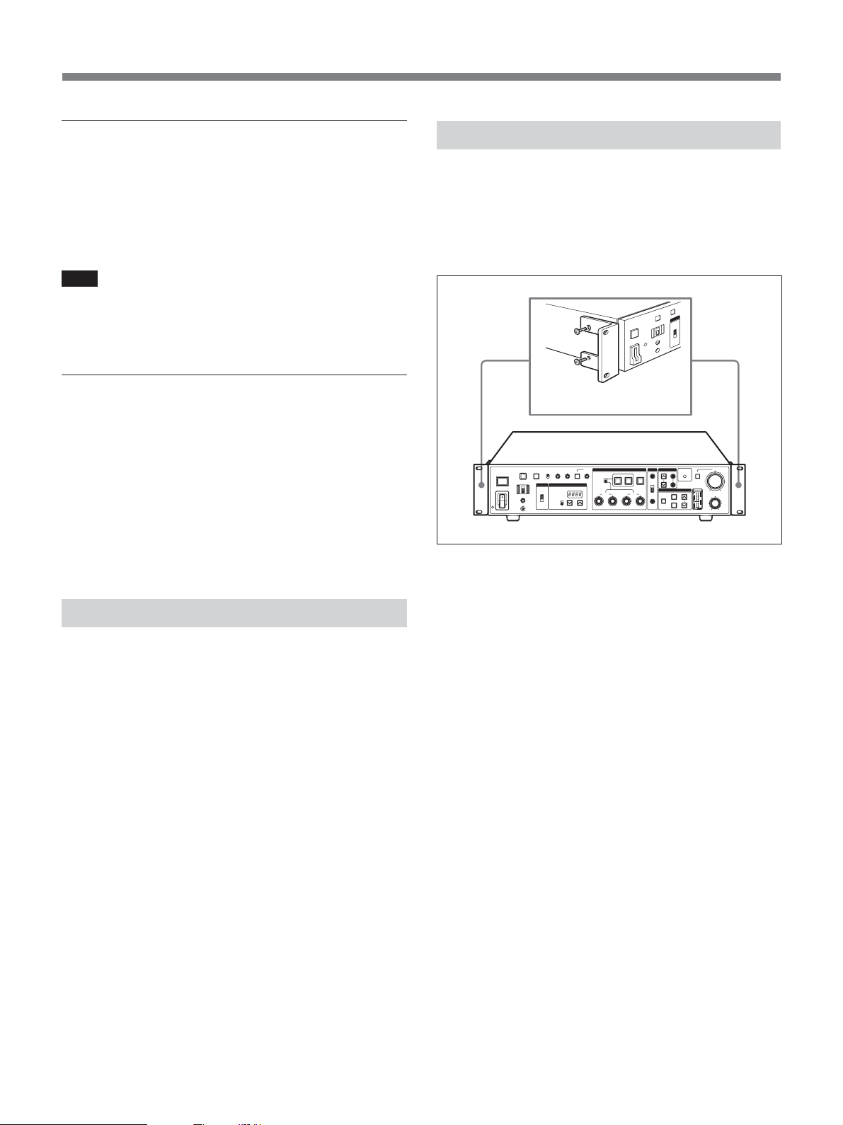
Rack Mounting
The unit can be mounted in a standard 19-inch studio
rack with the supplied mounting brackets.
For more information about rack mounting, contact your
Sony dealer or a Sony service representative.
Rack mounting brackets
(supplied)
Camera Cable Length
When using an optional CCZ-An camera cable (n in
the model name is a number expressing the cable
length in meters), analog transmission distance can be
extended up to a maximum of 300 meters (about 999
feet), and digital transmission distance can be extended
up to about 75 m (about 246 feet). Use the CABLE
COMP buttons (see page 17) on this unit to set a cable
compensation value according to the length of the
cable you are using.
When a DSR-370//370P/570WS/570WSP camcorder
is connected to this unit, reference sync signal and
return signal transmission distance can be extended up
to 150 m (about 492 feet).
8
Page 9
Connections
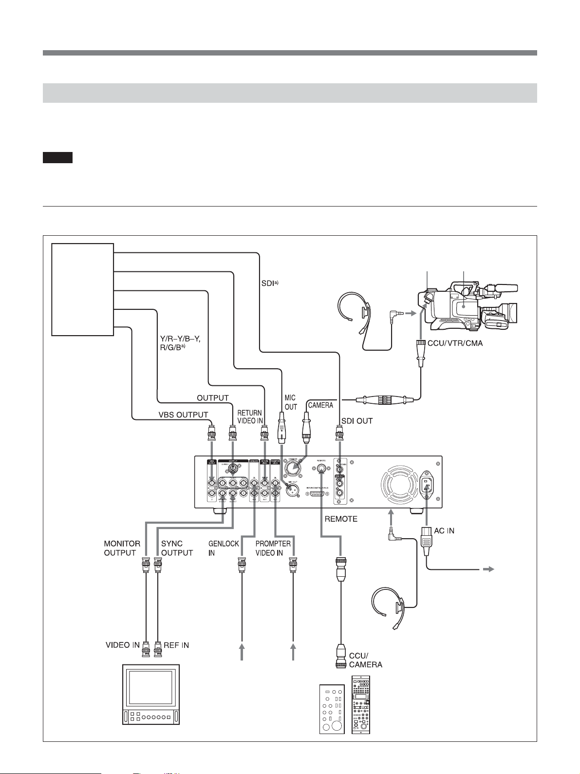
The following provides examples of how to connect
other devices to this unit.
Notes
•Be sure to power this unit off before connecting or
disconnecting camera cables.
When using one CCU-D50/D50P unit
Input
Input
Control console
a) SDI, Y/ R–Y/B–Y
and R/G/B are
enabled by system
setting DIP switches
on the front panel,
and by cabling
changes on the SDI
unit
(see pages 11
and 18)
b) The RCP-TX7 is not
.
available in EU
countries.
Output
Input
Input
•Some of the camera/camcorder’s switches and knobs
may not operate while this unit is connected to it.
For details, refer to the operation manual of the camera/
camcorder or camera adaptor.
CA-D50
Camera Adaptor
DR-100 headset
CCZZ-1E
extension connector
Camera
CCZ-An camera cable
CCU-D50/D50P Camera
Control Unit
Video monitor
Reference
sync signal
Prompter
signal
RM-M7G Remote
Control Unit
INTERCOM
(front panel)
CCA-7
connection
cable
DR-100 headset
Power cord (supplied)
RCP-TX7 Remote
Control Panel
b)
AC power
9
Page 10
Overview
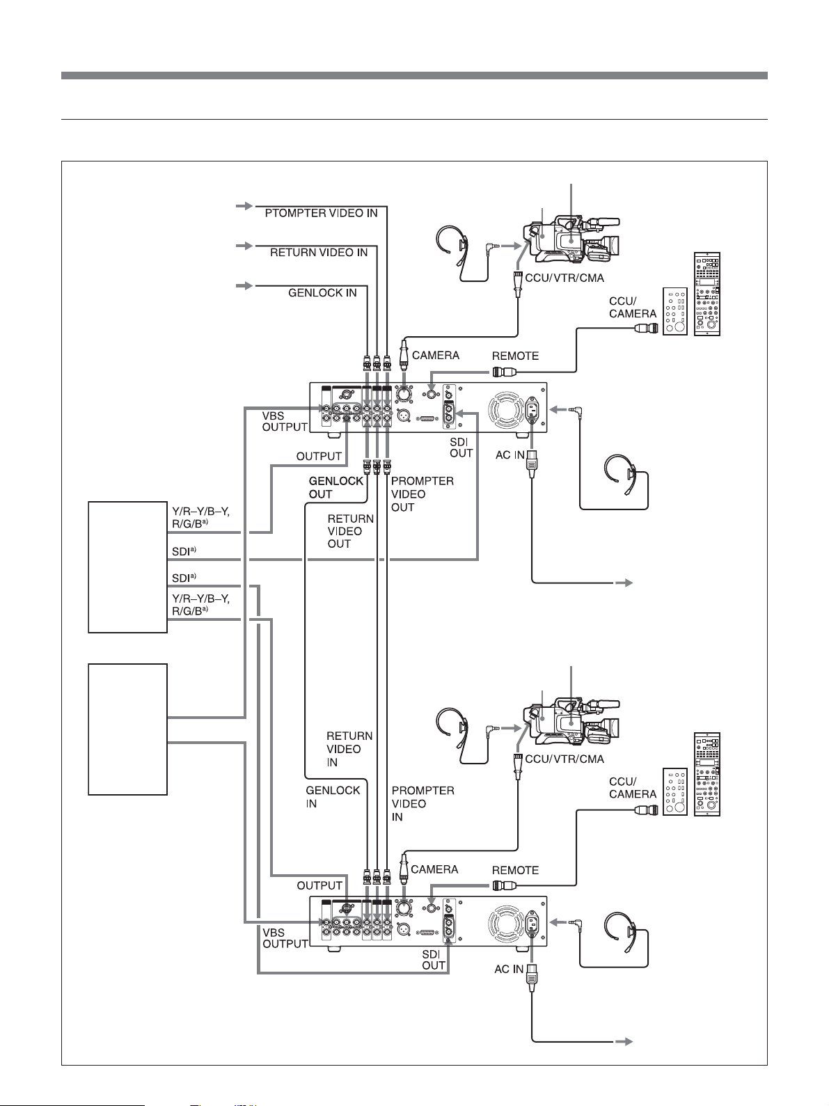
When using two CCU-D50/D50P units
Prompter signal
Return video signal
Reference sync signal
CA-D50 Camera Adaptor
DR-100
headset
Camera
RM-M7G
Remote
Control Unit
RCP-TX7
Remote
Control Panel
b)
VCR,
chroma
keyer, etc.
Switcher,
video
monitor, etc.
CCU-D50/D50P
Camera Control Unit
DR-100
headset
Power cord (supplied)
CA-D50 Camera
Adaptor
CCA-7
connection
cable
INTERCOM
(front panel)
Camera
DR-100
headset
AC IN AC power
RCP-TX7
Remote
Control Panel
RM-M7G
Remote
Control Unit
b)
a) SDI, Y/ R–Y/B–Y and R/G/B are enabled by system setting DIP
switches on the front panel, and by cabling changes on the SDI unit
(see pages 11 and 18)
b) The RCP-TX7 is not available in EU countries.
.
10
CCA-7
connection
cable
DR-100 headset
INTERCOM
(front panel)
AC power
Power cord (supplied)
Page 11

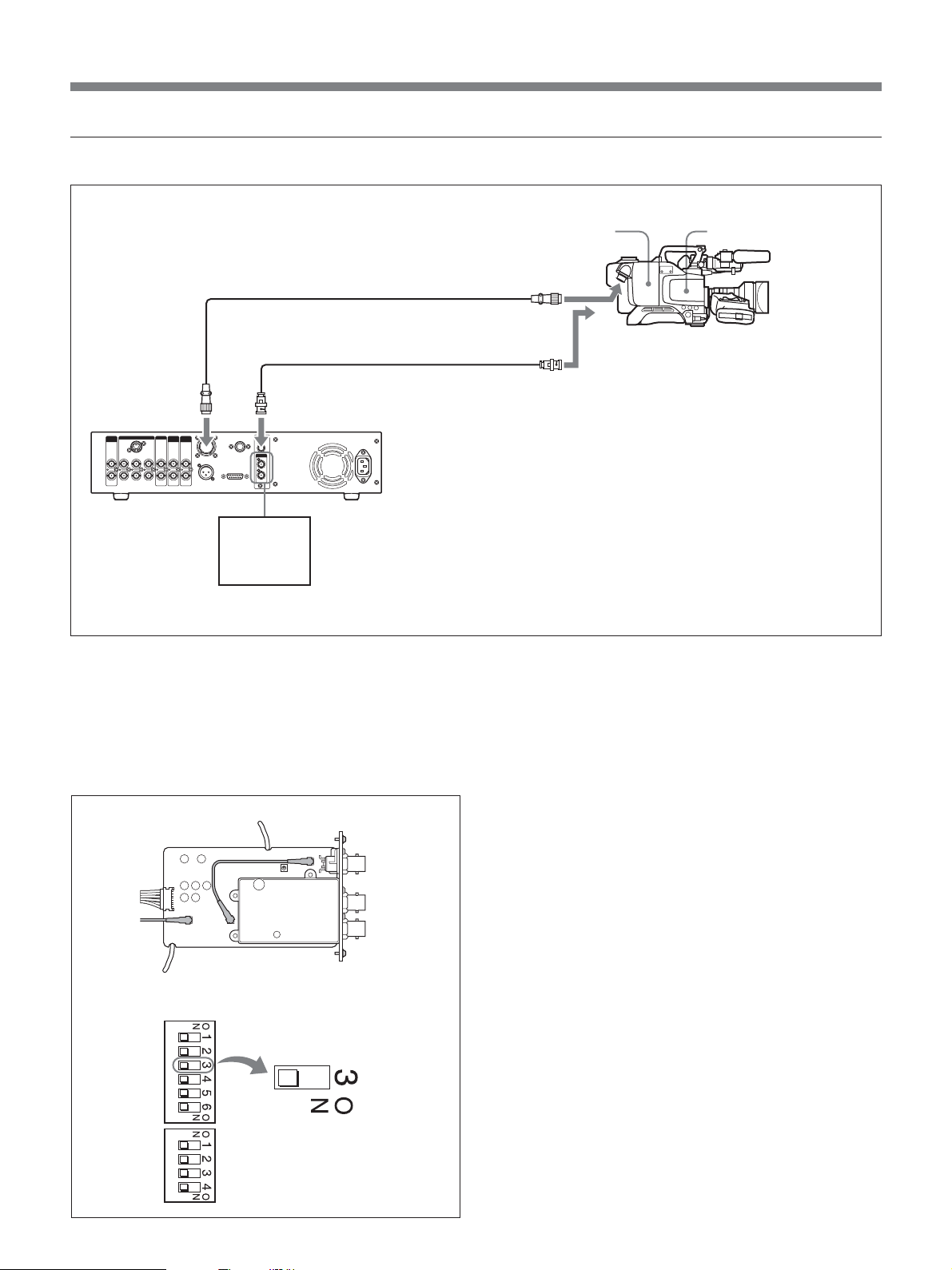
Connections for transmitting digital video (SDI) signals between this unit and a camera
In a system consisting of this unit, a DXC-D35/D35P/
D35WS/D35WSP camera, and CA-D50 Camera
Adaptor, digital video (SDI) signals can be transmitted
between this unit and the camera.
The maximum transmission distance over CCZ camera
cable is 75 m (246 feet). The maximum transmission
distance over coaxial cable is 200 m (656 feet). To
transmit over CCZ cable, you will need to change the
cabling in the SDI unit of this unit to SDI mode, and to
turn digital transmission on with the system setting
switches.
Connections for transmission over CCZ cable (max. length 75 m (246 feet))
CA-D50
Camera Adaptor
CCZ cable (max. length 75 m (246 feet))
CCU/VTR/CMA
Camera
CAMERA
CCU-D50/D50P
Camera Control Unit
SDI OUT
Switcher,
video
monitor,
VCR, etc.
Use the procedure described on the next page to
change the cabling in the SDI unit of this unit to SDI
mode, and turn digital transmission on with the system
setting switches.
Notes
•Set the system setting switches as soon as you change
the cabling.
•Y/R–Y/B–Y signals, RGB signals, and S-video
signals are not output when transmitting over CCZ
cable.
11
Page 12

Overview
1
2
S
D
I IN
Note
Be sure to power this unit off before proceeding to the
following operation.
1 Remove the two screws and gently pull the SDI
unit out.
Note
Be careful not to pull the SDI unit out too far.
Doing so may disconnect or damage the
connectors.
Screw
Screw
2 Open the cable holders of the SDI unit.
3 Change the connections for both cables as shown
below.
Before changed
(VBS mode)
After changed
(SDI mode)
4 Close the cable holders.
5 Repeat step 1 in reverse to return the SDI unit to
its original position.
6 Open the cover of the setting switches on the front
panel.
7 Set system setting switch 3 as shown below.
12
Page 13
Connections for transmission over RG cable (6/U or 6A/U) (max. length 200 m (656 feet))
CCZ-An camera cable
RG cable (6/U or 6A/U), max.
length 200 m (about 656 feet)
CAMERA
SDI IN
CCU-D50/D50P
Camera Control Unit
SDI OUT
Switcher,
video
monitor,
VCR, etc.
Check that the cabling in the SDI unit of this unit is set
to VBS mode, and that digital transmission is turned
off with the system setting switches. (See step 3 and 7
in “Connections for transmission over CCZ cable” on
page 11.)
CA-D50 Camera Adaptor
CCU/VTR/CMA
SDI OUT
Camera
SDI unit
Setting of system setting switch 3
VBS mode
13
Page 14

Overview
When Using the RM-M7G Remote Control Unit
The RM-M7G Remote Control Unit can be connected
directly to this unit. When this unit is powered on, it is
set up to control the camera/camcorder. If you have
connected an RM-M7G, do the following to set up this
unit and the RM-M7G for control from the RM-M7G.
1 Set the system setting switches (see “qh System
setting switches”on page 18) on the front panel of
this unit according to the connected device.
2 Do the following on the RM-M7G.
• Set the CAMERA SELECT switch to 1.
• Press the PANEL ACTIVE button.
To control the video camera from this unit
Press the PANEL ACTIVE button on the front panel.
Note
When the camera is being controlled from the front
panel of this unit or during automatic white/black
balance adjustment, the PANEL ACTIVE button on
the RM-M7G may not work. If this occurs, press the
RM-M7G PANEL ACTIVE button after completion of
the camera control operation from the front panel of
this unit or automatic white/black balance adjustment
operation.
14
Page 15

Location and Functions of Parts
Front Panel
1 TALLY/FAN ALARM indicator
2 LOCK switch
3 PANEL ACTIVE button
4 CALL button
5 GAIN switch
PANEL
TALLY/FAN ALARM
POWER
ACTIVE
LOCK
1
ON
OFF
INTERCOM
wa INTERCOM connector and volume knob
ws POWER switch
6 DETAIL knob
7 MASTER
CALL GAIN DETAIL KNEEMASTER
HIGH
LOW
OUTPUT SHUTTER
CAMERA
BARS
MID
CLEAR SCAN
GAMMA
SHUTTER SPEED/CABLE LENGTH
SHUTTER
OFF
ql SHUTTER adjustment section
w; Mode switch
GAMMA knob
8 KNEE
adjustment
section
AUTO
AUTO
PRESET
MANUAL
RBLACK B
9 WHITE/BLACK BALANCE adjustment section
q; PHASE adjustment section
qa CABLE COMP adjustment section
qs DIGITAL TRANSMISSION indicator
qd AUTO IRIS button
WHITE/BLACK BALANCE PHASE
BLACK WHITE ATW
RWHITE B
H
SC
I
CABLE COMP
DIGITAL
TRANSMISSION
SELECT FINE
Y
C
MENU
ENTER
SELECT
MENU
CANCEL
CAMERA CONTROL UNIT CCU-D50
AUTO
MASTER
BLACK
qh System setting switches
qj Intercom setting switches
Cover of the setting switches
qk MENU section
qf IRIS knob
IRIS
qg MASTER BLACK knob
1 TALLY/FAN ALARM indicator
Lights in red when a red tally signal is received, and
lights in green when a green tally signal is received.
Also lights when the CALL button of the camera/
camcorder or this unit is pressed.
This unit is equipped with a cooling fan. If the fan
should fail, this indicator flashes in red. Power the unit
off immediately and contact your Sony dealer or a
Sony service representative for repair. Continuing to
use the unit with a malfunctioning fan may shorten the
life of this unit.
You can attach the supplied camera number plates to
this indicator (see the following figure).
2 LOCK switch
Locks and unlocks the controls on this unit.
ON: Locks all controls on this unit except the CALL
button, the INTERCOM volume knob, and the
CABLE COMP buttons and CABLE COMP FINE
screws.
OFF: Unlocks the controls. Normally leave the
switch in this position.
15
Page 16

Location and Functions of Parts
3 PANEL ACTIVE button
When the camera/camcorder connected to this unit is
being controlled remotely by a remote control unit
such as the RM-M7G, pressing this button causes the
button to light up and assumes control of the camera/
camcorder from this unit. The controls on the front
panel are enabled while this button is lit. Pressing the
PANEL ACTIVE button on another device causes this
button to go off and transfers control of the camera/
camcorder away from this unit. This button flashes
while the camera/camcorder is powered off.
4 CALL button
Press to call the camera/camcorder operator over the
intercom. Pressing this button lights the tally indicators
in the camera’s viewfinder and on this unit.
5 GAIN switch
Selects one of three video amplifier gain levels (HIGH,
MID, LOW). The gain values corresponding to HIGH,
MID, and LOW are set by using the menu on the
camera/camcorder.
6 DETAIL knob
Rotate to adjust the contours of objects in the picture.
7 MASTER GAMMA knob
Adjusts the gamma curve. The central click position of
the KNEE/M.GAMMA/DETAIL knob corresponds to
the camera/camcorder preset value.
8 KNEE adjustment section
KNEE
AUTO
AUTO KNEE switch
KNEE knob
AUTO KNEE switch
Pressing this switch, lighting it, to activate the auto
knee circuits and adjust knee automatically.
9 WHITE/BLACK BALANCE adjustment section
WHITE/BLACK BALANCE switch
BLACK button
WHITE button
ATW button
WHITE/BLACK BALANCE
AUTO
PRESET
MANUAL
R BLACK B
Black balance
adjustment knobs
BLACK WHITE ATW
RWHITE B
White balance
adiustment knobs
WHITE/BLACK BALANCE switch
Selects the white and black balance adjustment mode.
AUTO: Selects auto adjustment mode, which allows
you to adjust the white or black balance by
pressing the WHITE or BLACK button. Adjusted
values are saved in camera/camcorder memory
and called up again when the switch is set to this
position again.
PRESET: The white balance value is returned to the
preset value. Black balance can be adjusted
automatically by pressing the BLACK button.
MANUAL: Selects manual mode, which allows you
to adjust the black and white balance with the
black balance and white balance adjustment
knobs.
BLACK (black balance automatic adjustment)
button
Adjusts the black balance automatically when the
WHITE/BLACK BALANCE switch is set to AUTO or
PRESET. This button lights when adjustment starts,
and goes off if adjustment is completed successfully. If
adjustment could not be completed successfully, this
button flashes for eight seconds at an intervals of about
0.5 seconds.
KNEE knob
Adjusts the knee point when the auto knee circuits are
off (when the AUTO KNEE switch is not lit).
16
Page 17

WHITE (white balance automatic adjustment)
button
Adjusts the white balance automatically when the
WHITE/BLACK BALANCE switch is set to AUTO or
PRESET. This button lights when adjustment starts,
and goes off if adjustment is completed successfully. If
adjustment could not be completed successfully, this
button flashes for eight seconds at an intervals of about
0.5 seconds.
ATW (auto tracking white balance) button
Press this button, lighting it, to adjust white balance
automatically according to changes in lighting
conditions.
SC (subcarrier phase adjustment) screw
After adjusting the subcarrier phase with the SC
switch, use a screwdriver or other tool to make fine
adjustments by rotating this screw.
qa CABLE COMP (cable compensation)
adjustment section
CABLE COMP
SELECT FINE
Y
C
CABLE COMP buttons
CABLE COMP FINE screws
Black balance adjustment knobs
Adjust the black level.
When the WHITE/BLACK BALANCE switch is set to
MANUAL, the R knob adjust red components and the
B knob adjusts blue components.
White balance adjustment knobs
Adjust the white level.
When the WHITE/BLACK BALANCE switch is set to
MANUAL, the R knob adjust red components and the
B knob adjusts blue components.
q; PHASE adjustment section
PHASE
H
H screw
SC switch
SC
I
SC screw
CABLE COMP (cable compensation) buttons
Use these button to adjust cable compensation for the
length of the cable you are using. The internal cable
compensation circuits prevent signal degradation by
adjusting for the length of the cable. Settings are
displayed in the SHUTTER SPEED/CABLE
LENGTH display window (see page 20).
To change a setting, press the upper or lower button
and keep it pressed for about one second. Then release
the button and press it again within two seconds. Press
and release the button quickly to display the current
setting for two seconds.
Set to “L 25” for a cable 10 m (about 33 feet) or less in
length.
CABLE COMP FINE (cable compensation fine
adjustment) screws
Makes fine compensation adjustments to the video
signal output from the VBS OUT connector. After
using the CABLE COMP buttons to adjust for cable
length, make fine adjustments by rotating these screws
with a screwdriver or other tool. The Y screw adjusts
the Y (luminance) signal, and the C screw adjusts the
C (chroma) signals.
H (horizontal phase adjustment) screw
Use a screwdriver or other tool to adjust the horizontal
phase difference between the output signal and an
external sync signal.
SC (subcarrier phase adjustment) switch
Adjust the subcarrier phase difference between the
output signal and an external sync signal.
qs DIGITAL TRANSMISSION indicator
Lit in green: Digital signals are being transmitted
from the camera/camcorder by CCZ cable or by
BNC cable connected to the SDI IN connector.
Lit in red: The unit is in digital transmission mode,
but there are no digital video signals being
transmitted from the camera/camcorder.
Flashing in red: The unit is in digital transmission
mode, but there are no digital or analog video
signals being transmitted from the camera/
camcorder because the cables are not connected or
because the camera/camcorder is powered off.
17
Page 18

Location and Functions of Parts
Not lit: The unit is not in digital transmission mode
(factory default setting).
qd AUTO IRIS button
Selects the iris adjustment mode. Before using this
button, set the IRIS switch on the camera/camcorder to
AUTO.
OFF (not lit): Manual adjustments can be made with
the IRIS knob.
ON (lit): The iris is adjusted automatically.
qf IRIS knob
When the AUTO IRIS button is off, adjust the camera/
camcorder lens iris by rotating this knob. When the
button is on, the iris is adjusted automatically.
qg MASTER BLACK knob
Adjusts the video signal black level.
qh System setting switches
Set the following items. Power this unit off before
setting switches.
Switch
Switch 1
Switch 2
Switch 3
Switch 4
Switch 5
Switch 6
Item
CCU command
mode
Return signal mode
Digital transmission
Output mode 1
Output mode 2
Remote/local
OFF (default)
M5A mode
Color
OFF
Y/R–Y/B–Y
Y/R–Y/B–Y
Remote
ON
TX7 mode
B/W
ON
R/G/B
Y/C
Local
Switch 1: CCU command mode
OFF: Use CCU-M5A system commands (M5A
mode). This unit can be used to carry out similar
control operations to those available with the
CCU-M5A/M5AP.
ON: Use CCU-TX7 system commands (TX7 mode).
Select ON (TX7 mode) when this unit is used with
CA-D50. The RCP-TX7 (not available in EU
countries) can be used in TX7 mode.
Set to off (M5A mode) when this unit is connected to a
DSR-370/370P/570WS/570WSP or when this unit is
connected to a camera via a CA-537/537P.
Switch 2: Return signal mode
OFF: Transmit color as the return signal.
ON: Transmit B/W as the return signal.
Prompter signals cannot be transmitted when color is
selected. Select B/W when using prompter signals.
Switch 3: Digital transmission
ON: Selects digital transmission between this unit
and the camera adaptor.
OFF: Selects analog transmission between this unit
and the camera adaptor.
For digital transmission, cabling must be changed in
the SDI unit of this unit.
Switches 4 and 5: Output mode 1 and output
mode 2
Select the type of analog signal output from this unit.
Y/R–Y/B–Y: Output Y, R–Y, and B–Y signals from
the Y/G/Y, R–Y/R/C, and B–Y/B OUTPUT
connectors. Set the switches as follows.
Switch 4 OFF
Switch 5 OFF
Nothing is output from the S VIDEO connector.
R/G/B: Output G, R, and B signals from the Y/G/Y,
R–Y/R/C, and B–Y/B OUTPUT connectors. Set
the switches as follows.
Switch 4 ON
Switch 5 – (ON/OFF both OK)
Nothing is output from the S VIDEO connector.
Y/C: Output S-video signals from the S VIDEO
OUTPUT connector. Set the switches as follows.
Switch 4 OFF
Switch 5 ON
Note
When switch 3 (digital transmission) is on, the settings
of switches 4 and 5 are ignored and no signals are
output from any of the Y/G/Y, R–Y/R/C, and S
VIDEO connectors.
18
Page 19

Switch 6: Remote/local
When switch 1 (CCU command mode) is set to on
(TX7 mode), selects whether to control the camera/
camcorder from a device connected to the REMOTE
connector on the rear panel of this unit or from the
front panel.
OFF: Operations on the device connected to the
REMOTE connector receive priority.
ON: Operations on the front panel of this unit receive
priority.
Note
This switch is disabled when an RM-M7G is
connected.
qj Intercom setting switches
Set the intercom mode using switches 1 to 3. Switch 4
is not used.
Power this unit off before setting switches.
qk MENU section
MENU button
ENTER button
MENU
ENTER
SELECT
MENU
CANCEL
SELECT up and
CANCEL button
down buttons
MENU button and indicator
When you press the MENU button, the indicator lights
and a menu is displayed on the monitor connected to
the MONITOR OUT connector.
On how to change system settings, see page 26.
Setting to 4W mode
Switch 1 INCOM mode 1 OFF
Switch 2 INCOM mode 2 OFF
Switch 3 INCOM mode 3 OFF
Setting to 2W mode
Switch 1 INCOM mode 1 ON
Switch 2 INCOM mode 2 – (ON/OFF both OK)
Switch 3 INCOM mode 3 – (ON/OFF both OK)
Setting to RTS mode
Switch 1 INCOM mode 1 OFF
Switch 2 INCOM mode 2 ON
Switch 3 INCOM mode 3 – (ON/OFF both OK)
Setting to CLEARCOM mode
Switch 1 INCOM mode 1 OFF
Switch 2 INCOM mode 2 OFF
Switch 3 INCOM mode 3 ON
SELECT up and down buttons
Use to switch between menu pages or settings display
pages, to move the arrow within a menu, and to change
menu item settings.
ENTER button
Confirms the settings made with the SELECT up and
down buttons.
CANCEL button
Cancels the currently selected state and returns the
item to its original state.
Note
Always set to 4W mode when there is nothing
connected to the INTERCOM/TALLY/AUX
connector on the rear panel of this unit. The intercom
system may not operate correctly if this switch is set to
another mode.
For more information about intercom system connections,
contact your Sony dealer or a Sony service representative.
19
Page 20

Location and Functions of Parts
ql SHUTTER adjustment section
SHUTTER SPEED/CABLE LENGTH display window
SHUTTER
SHUTTER SPEED/CABLE LENGTH
SHUTTER
OFF
CLEAR SCAN
SHUTTER buttons
SHUTTER switch
SHUTTER switch
Selects whether or not to use electronic shutter.
SHUTTER: Turns the normal shutter function on.
OFF: Do not use the shutter function.
CLEAR SCAN: Use the clear scan function.
SHUTTER buttons
When the SHUTTER switch is set to CLEAR SCAN
or SHUTTER, change the shutter speed or clear scan
frequency setting as follows.
When the SHUTTER switch is set to CLEAR
SCAN: Change the clear scan frequency while the
button is kept pressed. Press the
increase the frequency and the
button to
button to
decrease it. Presssing both buttons simultaneously
resets clear scan frequency to its factory default
value.
When the SHUTTER switch is set to SHUTTER:
Change the shutter speed in units of 1 while the
button is kept pressed. Press the
increase the speed and the
button to
button to decrease
it.
SHUTTER SPEED/CABLE LENGTH display
window
When the SHUTTER switch is set to CLEAR SCAN
or SHUTTER, displays the shutter speed or clear scan
frequency. When the SHUTTER switch is set to OFF,
displays “OFF”. When the CABLE COMP button (see
page 17) is pressed, displays the letter “L” followed by
the length of the cable (unit meters).
w; Mode switch
Selects the output signal from this unit.
CAMERA: Camera signal.
BARS: Color bars signal.
wa INTERCOM connector (minijack) and volume
knob
Connect a headset such as the DR-100. Adjust the
headset speaker volume with the volume knob.
ws POWER switch
Press the “
unit off, press the “
” side to power this unit on. To power the
” side of this switch.
Note
When EVS is set to ON, “EVS” is displayed. When
TLCS is set to ON, “----” is displayed. The shutter
speed and clear scan frequency cannot be changed in
these cases.
For more information about EVS and TLCS settings, see
“Changing Settings” on page 26.
20
Page 21

Rear Panel
1 VBS OUTPUT 1 and 2 connectors
2 S VIDEO connector
3 Y/G/Y, R–Y/R/C, B–Y/B connectors
4 RETURN VIDEO IN and OUT connectors
5 CAMERA connector
VBS
OUTPUT
12Y/G/Y
MONITOR
OUTPUT
S VIDEO
OUTPUT
R-Y/R/C
SYNC
OUTPUT
B-Y/B IN
GENLOCK
OUT
RETURN
VIDEO
IN
OUTINOUT
PROMPTER
VIDEO
CAMERA
MIC OUT
q; MIC OUT connector
qa PROMPTER VIDEO IN and OUT connectors
6 REMOTE connector
7 SDI IN and OUT connectors
REMOTE
INTERCOM/TALLY/AUX
SDI OUT
SDI IN
1
2
9 INTERCOM/TALLY/AUX connector
8 - AC IN connector
qs GENLOCK IN and OUT connectors
qd Spare connector
qf SYNC OUTPUT connector
qg MONITOR OUTPUT connector
1 VBS OUTPUT (composite video output) 1 and 2
connectors (BNC type)
Output composite video signals. Both connectors
output the same signal.
2 S VIDEO (S-video output) connector (Mini-DIN,
4-pin)
Outputs S-video signals.
3 Y/G/Y, R–Y/R/C, B–Y/B (video output)
connectors (BNC type)
Output R/G/B signals, Y, R–Y, B–Y component
signals, or YC signals.
4 RETURN VIDEO IN and OUT connectors
(BNC type)
During on-air transmission or recording, the IN
connector accepts signals from devices such as a
control console or special effect generator, and the
OUT connector supplies the same signal to the camera
viewfinder. These connectors have a loop-through
configuration, with the signal input to the IN connector
being directly output from the OUT connector. The
OUT connector is terminated automatically when
nothing is connected to it.
21
Page 22

Location and Functions of Parts
Note
When using B/W return mode (see “qh System setting
switches” on page 18) and inputting a return video
signal to the RETURN VIDEO IN connector, always
input a reference sync signal to the GENLOCK IN
connector to synchronize the return video signal with
the sync signal. Failure to synchronize the return video
signal with a sync signal can cause camera/camcorder
synchronization to become unstable.
5 CAMERA connector (Z-type, 26-pin)
Connect a CCZ-An camera cable (not supplied) here to
connect this unit to devices such as a CA-D50 camera
adaptor on the camera.
6 REMOTE connector (10-pin)
Using an CCA-7 connection cable (not supplied),
connect to an RM-M7G Remote Control Unit (not
supplied) or an RCP-TX7 (not supplied). The RCPTX7 is not available in EU countries.
7 SDI IN and OUT connectors
These are input and output connectors for digital video
(SDI) signals.
8 -AC IN connector
Connect to an AC power source using the supplied
power cord.
9 INTERCOM/TALLY/AUX connector (D-sub,
15-pin)
Inputs and outputs tally and intercom signals. Connect
to the tally/intercom connector of the intercom system.
INTERCOM/TALLY/AUX connector pin
assignment
No. Signal name Description
1 AUX-RX (X) Contact your Sony dealer or a
9 AUX-TX (X)
2 AUX/TALLY (G) Gnd (AUX, tally)
q; G TALLY IN ON: Gnd
3 R TALLY IN OFF: Open
qa 4W (G) IN
4 4W (X) IN 4-wire talk, 0 dBu a), balanced
qs 4W (Y) IN
5 2W (X) IN/OUT 2-wire, 0 dBu
qd 2W (G) IN/OUT
6 RTS (G) IN/OUT 2-wire 0 dBu
qf RTS (X) IN/OUT Termination required
7 4W (Y) OUT
qg 4W (G) OUT 4-wire receive, 0 dBu
8 4W (X) OUT
a) 0 dBu = 0.775 Vrms
Sony service representative.
a)
Termination required
(recommended termination
impedance: 600 ohms)
a)
(recommended termination
impedance: 200 ohms)
a)
, balanced
q; MIC OUT (microphone output) connector
(XLR, 3-pin)
Outputs microphone signals from the camera/
camcorder.
qa PROMPTER VIDEO IN and OUT connectors
(BNC type)
Input and output connectors for prompter signals. The
IN and OUT connectors have a loop-through
configuration, with the signal input to the IN connector
being directly output from the OUT connector. The
OUT connector is terminated automatically when
nothing is connected to it.
22
87654321
15 14 13 12 11 10 9
qs GENLOCK IN and OUT connectors (BNC type)
The IN connector accepts a reference video signal
(black burst or composite video) for external sync. The
IN and OUT connectors have a loop-through
configuration, with the signal input to the IN connector
being directly output from the OUT connector. The
OUT connector is terminated automatically when
nothing is connected to it.
qd Spare connector
This is a spare connector, not currently used.
Page 23

qf SYNC OUTPUT connector (BNC type)
Outputs a sync signal from the camera/camcorder.
qg MONITOR OUTPUT connector (BNC type)
Outputs composite video signals for a monitor. When
you press the MENU button and the SELECT up and
down buttons on the front panel of this unit,
information about system settings is superimposed
over the video signals output from this connector.
23
Page 24
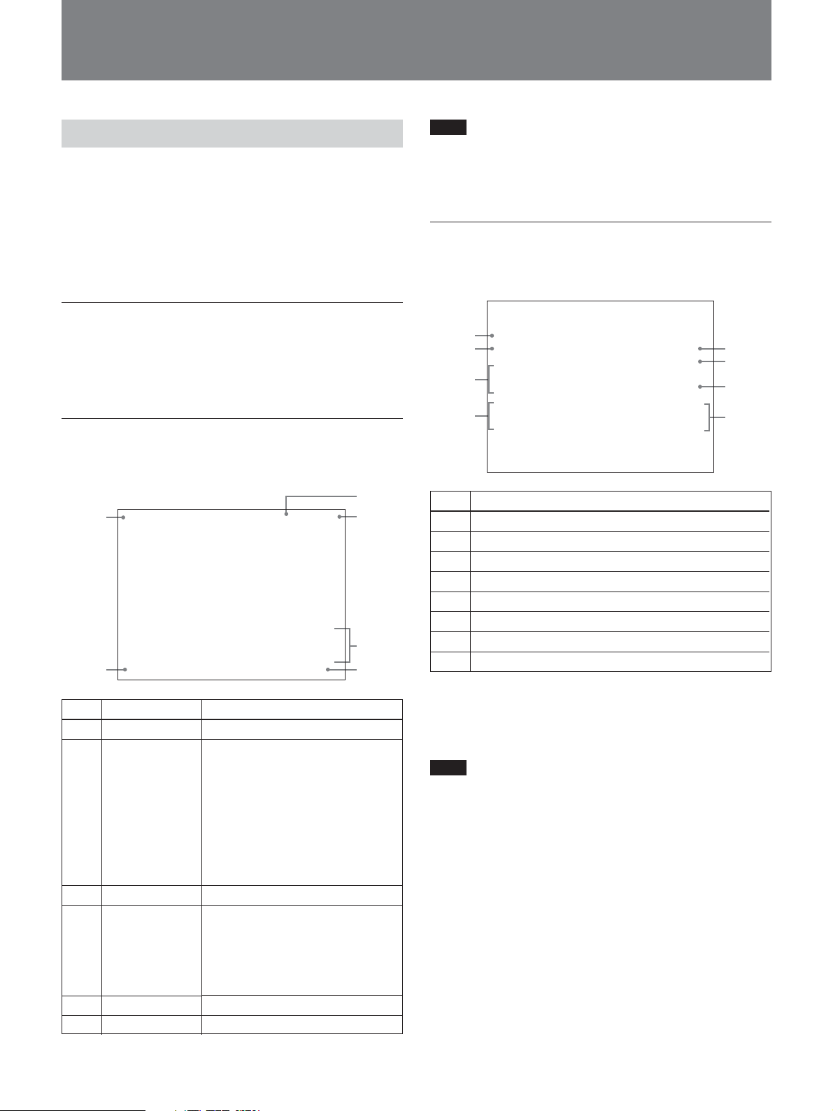
Displaying and Changing Settings
2
Displaying Settings
When the MENU button on the front panel is unlit, the
SELECT up and down buttons can be used to display
automatic adjustment items and the current state of the
CCU-D50/D50P on a monitor connected to the
MONITOR OUT connector. The SELECT up and
down buttons can also be used to change pages.
Initial page
The initial page appears immediately after the unit is
powered on.
Nothing is displayed on the initial page.
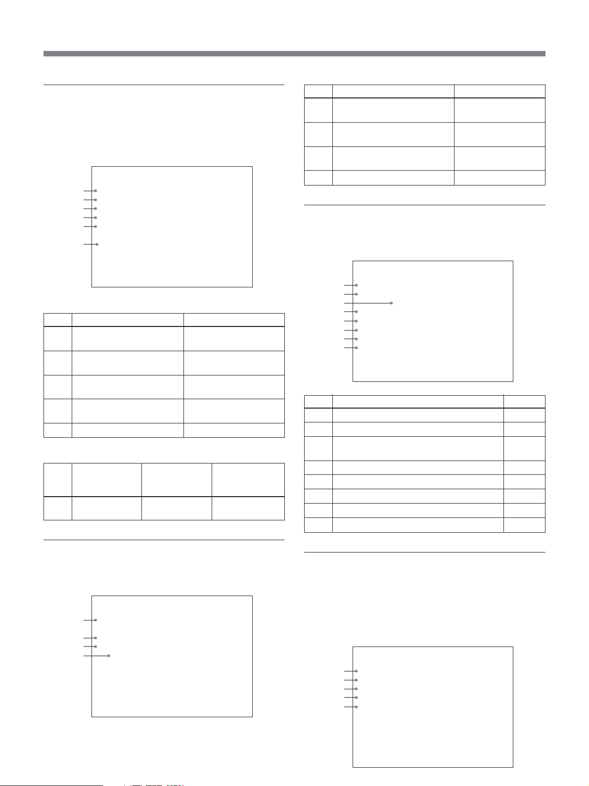
Page 1: Normal page
Page 1 displays the current settings of the camera/
camcorder.
LOW 1/2000
1
5
F: 16IRIS: AUTO
ON
3
4
6
Note
The F value does not appear when the CCU command
mode (see “qh System setting switches” on page 18) is
set to off (M5A mode).
Page 2: Control page
Page 2 displays the control settings made on this unit
or from the connected control device.
White
1
R: 22
B: -54
2
KNEE
3
-12
DTL
4
6
No.
Setting item
1
White balance - red
2
White balance - blue
3
Knee adjustment
4
Detail
5
Black balance - red
6
Black balance - blue
7
Master black
8
Master gamma
Black
R: 55
B: 44
M: -22
M. GAM
-10
5
6
7
8
No.
Item
1
Master gain
2
Shutter/clear
scan speed
3
Shutter on/off
4
AWB/ABB
progress and
result
5
Iris mode
6
F value
Value
LOW/MID/HIGH
When the SHUTTER switch is set
to SHUTTER:
1
/100 to 1/2000 (NTSC), 1/60 to 1/2000
(PAL)
When the SHUTTER Switch is set
to CLEAR SCAN:
60.4 Hz to 200.3 Hz (NTSC),
50.3 Hz to 201.4 Hz (PAL)
When EVS is set to ON: EVS
When TLCS is set to ON: TLCS
ON/OFF
1st line: AWB (automatic white
balance adjustment) or ABB
(automatic black balance
adjustment)
2nd line: Progress of adjustment
3rd line: Result of adjustment
AUTO/MANUAL
CLOSE, F:1.4 to F:16
a)
a) A GAIN value is displayed during operations on RCP-
TX7.
24
When the WHITE/BLACK BALANCE switch (see
page 16) is set to AUTO or PRESET, AUTO or
PRESET appears instead of a numeric value.
Note
The master gamma value does not appear when the
CCU command mode (see “qh System setting
switches” on page 18) is set to off (M5A mode).
Page 25
Displaying and Changing Settings
Page 3 System Setting page
Page 3 displays the current settings of the system
including this unit, made by the system setting
switches and intercom setting switches (see page 19)
on the front panel of this unit.
*System Setting*
1
COMMAND MODE
RETUREN
2
3
DIGITAL TRANS
OUTPUT
4
COMMAND
5
INCOM
6
Settings by system setting switches
No.
Description
1
CCU command mode
Value
M5A, TX7
(switch 1)
2
Return signal mode
COLOR, B/W
(switch 2)
3
Digital transmission
ON, OFF
(switch 3)
4
Output mode (switches 4
Y/C, R/G/B, Y/B–Y/R–Y
and 5)
5
Remote/local (switch 6)
REMOTE, LOCAL
Settings by intercom setting switches
No.
Description
6
Intercom mode
setting
Value
4W, 2W, RTS,
CLEARCOM
TX7
COLOR
OFF
R/G/B
LOCAL
4W
Intercom
setting switch
number
1, 2, 3
No.
Description
1
Cable compensation value
Value
25/50/75/100/150/
200/250/300 m
2
Horizontal phase adjustment
–99 to 99
value
3
Subcarrier phase fine
–99 to 99
adjustment value
4
Subcarrier phase adjustment
0/180
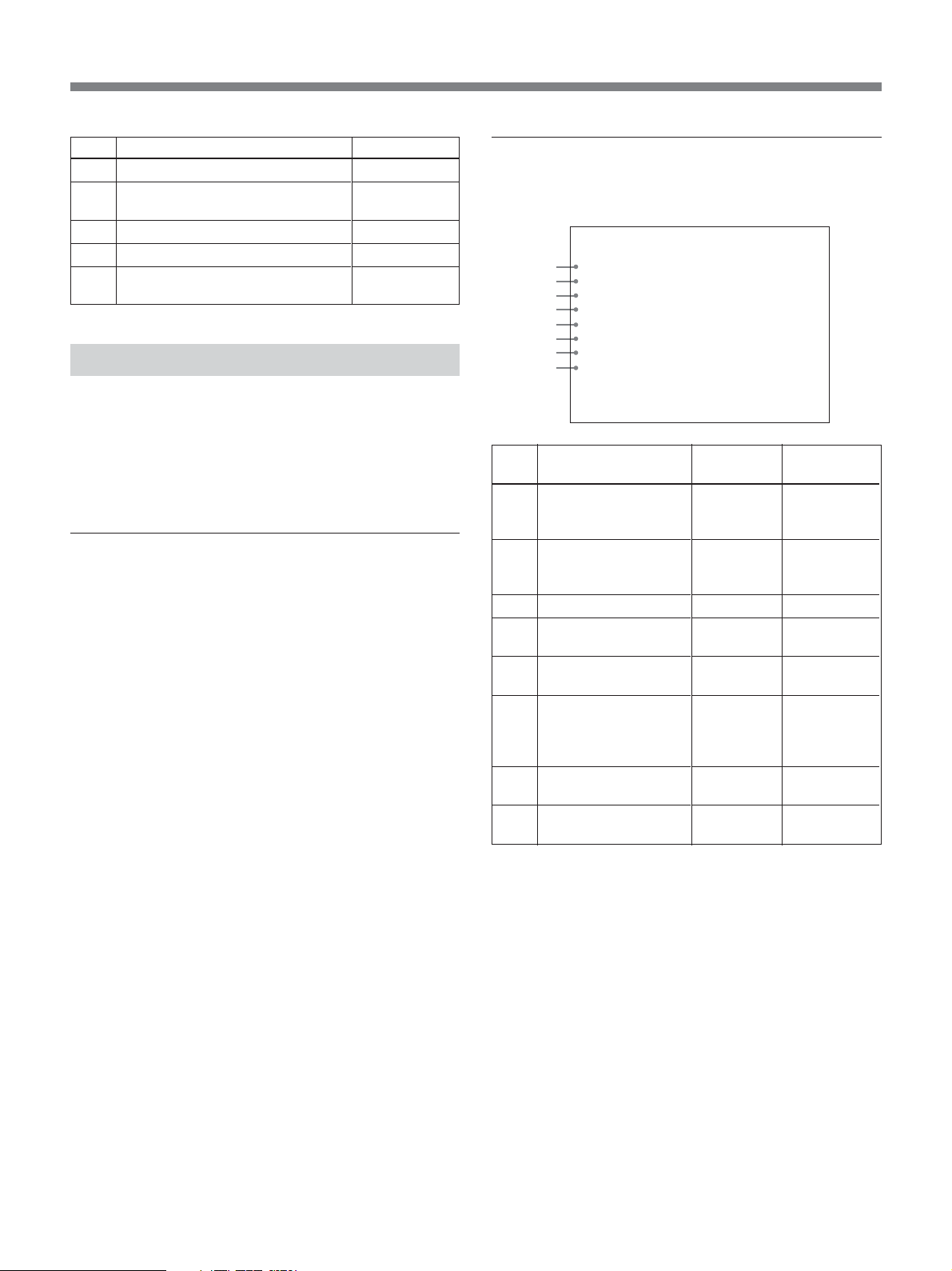
Page 5: Diagnosis page
Page 5 displays the results of CCU-D50/D50P selfdiagnostics.
*Diagnosis*
1
CAMERA Sync
COMMAND CAMERA
2
3
RCP
4
FAN
SYSTEM
5
MEMORY
6
PANEL
7
CCU SDI IN
8
No.
Description
1
Whether sync is being input from camera
2
Status of Command Link with camera
3
Status of Command Link with remote
control panel/unit
4
Status of power fan
5
Other CPU status
6
Status of front panel status memory
7
Status of connection with rear panel
8
Presence of SDI input from CCU
OK
OK
OK
OK
OK
OK
OK
IN
Value
OK, NO
OK, NO
OK, NO
OK, NG
OK, NG
OK, NG
OK, NG
IN, NO
Page 4: System Setting page
Page 4 displays the current settings of the system
including this unit, made on the front panel of this unit.
*System Setting*
1
2
3
4
Cable Comp
H-Phase
SC-Phase
0/180
100m
12
-22
0
Page 6: CA Setting (CA-D50 settings) page
Page 6 displays the current settings of CA-D50.
Nothing is displayed when a CA-D50 is not connected,
when a camcorder is in use, and when the CCU
command mode (see “qh System setting switches” on
page 18) is set to off (M5A mode).
*CA Setting*
1
2
3
4
5
SDI PLL
CABLE COMP
RETURN
SKIN GATE
OUTPUT
OK
ON
COLOR
ON
R/G/B
25
Page 26
No.
Description
1
CA SDI PLL status
2
200 m (656 feet) cable
compensation setting
3
Return signal mode
4
SKIN-GATE MIX function setting
5
Output mode setting
Value
OK, NG
ON, OFF
COLOR, B/W
ON, OFF
Y/C, R/G/B,
Y/B–Y/R–Y
Changing Settings
When the MENU button on the front panel is lit, a
menu appears on the monitor connected to the
MONITOR OUT connector, allowing you to change
the settings of the system including this unit.
To operate the menu
Proceed as follows.
1 Press the MENU button on the front panel, turning
it on.
A menu appears on the monitor connected to the
MONITOR OUT connector.
2 Press the SELECT up or down button to select a
page, and then press the ENTER button.
3 Press the SELECT up or down button to select a
menu item, and then press the ENTER button.
4 Press the SELECT up or down button to select a
setting for the item, and then press the ENTER
button.
Press the CANCEL button to return to the previous
state.
Page1: Setup Menu page
This page controls camera/camcorder and CCU
functions.
*Setup Menu*
1
MATRIX
IRIS
2
3
EVS
4
TITLE
CLOCK
5
6
RCP RATE
7
TLCS
SKIN DTL
8
No.
Function
1
Switch color matrix
function.
2
Switch AUTO IRIS
mode.
3
Turn EVS on and off.
4
Turn TITLE display on
and off.
5
Turn time display on
and off.
6
Set communications
speed for REMOTE
connector on the rear
panel.
7
Turn TLCS function on
and off.
8
Turn skin detail
function on and off.
a)
b)
c)
d)
a) This can also be set for the DXC-D35/D35WS series, but
the setting is ignored.
b) When the CCU command mode (see “qh System setting
switches” on page 18) is set to on (TX7 mode), the
selections for this item are CAM, BARS, and OFF.
When the CCU command mode is set to off (M5A
mode), the selections for this item are ON and OFF. For
details, refer to the operation manual of the camera/
camcorder.
c) Always select 38400 when a RCP-TX7 (not available in
EU countries) is connected. Selecting anything other than
38400 will prevent a connection from being made.
d) This item does not appear when the CCU command mode
is set to off (M5A mode).
: STANDARD
: STANDARD
: OFF
: OFF
: OFF
: 38400
: OFF
: OFF
Settings
STANDARD,
COLORFUL,
FL LIGHT
STANDARD,
SPOT 1.,
BACK 1.
ON, OFF
ON, OFF
CAM,
BARS, OFF
38400, 9600
ON, OFF
ON, OFF
d)
Factory
default setting
STANDARD
STANDARD
OFF
OFF
OFF
38400
OFF
OFF
26
Page 27

Displaying and Changing Settings
Page 2: Volume PRESET page
This page allows you to set the control values for the
center click positions of the knobs on the front panel of
this unit to 0 or to the factory default values.
*Volume PRESET*
1
ALL
RESET
2
3
DETAIL
4
M.GAMMA
KNEE
5
No.
Description
1
Sets the control values of all knobs to 0.
2
Returns all knobs to the factory default control
values.
3
Sets the control value of the DETAIL knob only to 0.
4
Sets the control value of the MASTER GAMMA
knob only to 0.
5
Sets the control value of the KNEE knob only to 0.
OK
OK
OK
OK
To set center values
Proceed as follows.
1 Press the SELECT up and down buttons to select
the menu item for the knob that you want to adjust.
2 Rotate the knob for the item selected in step 1 to
the center click position.
3 Press the ENTER button.
The control value for the center click position is set
to 0.
27
Page 28

Notes on Use
Use and storage locations
Avoid using or storing the unit in the following places:
•Where it is subject to extremes of temperature.
•Near a heat source, such as a radiator or an air duct,
or in a place subject to direct sunlight. (Note that in
summer the temperature in a car with the windows
closed can reach 50°C (122°F).)
•Very damp or dusty places.
•Where rain is likely to reach the unit.
•Places subject to severe vibration.
•Near strong magnetic fields.
•Near transmitting stations generating strong radio
waves.
Avoid violent impacts
Dropping the unit, or otherwise imparting a violent
shock to it, is likely to cause it to malfunction.
Do not cover with cloth
While the unit is in operation, do not cover it with a
cloth or other material. This can cause the temperature
to rise, leading to a malfunction.
After use
Turn the unit off.
Care
If the body of the unit is dirty, wipe it with a dry cloth.
For severe dirt, use a soft cloth steeped in a small
amount of neutral detergent, then wipe dry. Do not
use volatile solvents such as alcohol or thinners, as
these may damage the finish.
Regarding the transport of this unit
Keep the original carton and associated packing
material, and use them when transporting the unit.
During transport, do not subject the unit to strong
shocks.
28
Page 29

Specifications
General
Power requirements
CCU-D50: 100 to 120 V AC,
60 Hz
CCU-D50P: 220 to 240 V AC,
50 Hz
Power consumption
CCU-D50: 1.7 A (entire system
operating, 100 to 120 V AC)
CCU-D50P: 0.8 A (entire system
operating, 220 to 240 V AC)
Peak inrush current
(1) Power ON, current probe
method: 20A (240V), 6A (100 V)
(2) Hot switching inrush current,
mesured in accordance with
European standard EN 55103-1:
12A (230 V)
Rated maximum load to camera
4 A, 13 V (at receiving end)
Operating temperature
5°C to 40°C (41°F to 104°F)
Storage temperature
–20°C to +55°C (–4°F to +131°F)
Dimensions (w/h/d, excluding protrusions)
424 × 88 × 283 mm (16
1
/4 inches)
11
Mass Approx. 6.3 kg (13 lb 14 oz)
3
/4 × 3 1/2 ×
Output connectors
SYNC OUT BNC type (1)
0.3 Vp-p, negative-sync, 75 Ω,
unbalanced
MONITOR OUT BNC type (1)
VBS: 1.0 Vp-p, negative-sync,
75 Ω, unbalanced
MIC OUT XLR 3-pin (male) (1)
SDI OUT 1/2 BNC type (1 each)
0.8 Vp-p, 75 Ω, 270 Mbps
Input connectors
GENLOCK IN/OUT
BNC type (1 each)
VBS: 1.0 Vp-p or black burst (0.45
Vp-p), loop-through, 75 Ω
automatic termination
CAMERA Z type 26-pin (1)
TALLY/INTERCOM/AUX
D-sub 15-pin (1)
INTERCOM Minijack (1)
SDI IN BNC type (1)
0.8 Vp-p, 75 Ω, 270 Mbps
REMOTE 10-pin (1)
RETURN VIDEO IN/OUT
BNC type (1 each)
VBS (1.0 Vp-p), loop-through,
75 Ω automatic termination
PROMPTER VIDEO IN/OUT
BNC type (1 each)
VBS (1.0 Vp-p), loop-through,
75 Ω automatic termination
VBS OUT 1/2 BNC type (1 each)
VBS: 1.0 Vp-p, negative-sync,
75 Ω, unbalanced
S VIDEO Mini DIN 4-pin (1)
Y: 1.0 Vp-p, negative-sync, 75 Ω,
unbalanced
C: 0.286 Vp-p (burst), no sync
Y/G/Y, R–Y/R/C, B–Y/B
BNC type (1 each) (switchable)
R, G, B: 0.7 Vp-p, 75 Ω, no sync
Y: 1.0 Vp-p, negative-sync, 75 Ω,
unbalanced
R–Y, B–Y: 0.700 Vp-p (CCU-D50)
or 0.525 Vp-p (CCU-D50P), no
sync, 75 Ω, unbalanced
Y: 1.0 Vp-p, negative-sync, 75 Ω,
unbalanced
C: 0.286 Vp-p (burst), no sync
Adjustable items
Iris Automatic/manual
White balance Automatic/manual/preset
R, B output levels adjustable
Automatic tracking
Black balance Automatic/manual
R, B black levels adjustable
Video amplifier gain level
Master black level
Knee point Automatic/manual
Detail level
Gamma compensation
Electronic shutter speed
Clear Scan
29
Page 30

Specifications
Video output signal selection
Camera/color bars
Tally/intercom level
SC phase
H phase
Cable compensation
Accessories supplied
Rack mount brackets (2)
Screws for rack mounting (4)
AC power cord (1)
Camera number plates (1 set)
DIP switch label (1)
SDI switch label (1)
Operating Instructions (1)
CD-ROM Manual (1)
Warranty card (1)
Optional accessories
Design and specifications are subject to change
without notice.
If you wish to use the INTERCOM/TALLY/AUX
connector, be sure to consult your Sony dealer or a
Sony service representative.
Color video camera
DXC-D35/D35P, DXC-D35WS/
D35WSP
Camera adaptor CA-D50
DV camcorder DSR-370/370P, DSR-570WS/
570WSP
Studio system devices
Remote control unit
RCP-TX7 (not available in EU
countries), RM-M7G
Headset DR-100
Camera cable CCZ-A2 (2 meters, about 7 feet),
CCZ-A5 (5 meters, about 17
feet), CCZ-A10 (10 meters, about
33 feet), CCZ-A25 (25 meters,
about 83 feet), CCZ-A50 (50
meters, about 166 feet), CCZ-
A100 (100 meters, about 333
feet)
Extension connector for CCZ-A series camera cable
CCZZ-1B (fixed on wall), CCZZ-
1E
30
Page 31

Sony Corporation
 Loading...