

Page 1

CAMERA CONTROL UNIT
CCU-900/900P
DIGITAL INTERFACE UNIT
BKP-9330
OPERATION MANUAL
1st Edition (Revised 3)
[English]
Page 2

Page 3
WARNING
To prevent fire or shock hazard, do not
expose the unit to rain or moisture.
To avoid electrical shock, do not open
the cabinet. Refer servicing to qualified
personnel only.
AVERTISSEMENT
For customers in the USA (for CCU-900)
This equipment has been tested and found to comply with
the limits for a Class A digital device, pursuant to Part 15 of
the FCC Rules. These limits are designed to provide
reasonable protection against harmful interference when the
equipment is operated in a commercial environment. This
equipment generates, uses, and can radiate radio frequency
energy and, if not installed and used in accordance with the
instruction manual, may cause harmful interference to radio
communications. Operation of this equipment in a residential
area is likely to cause harmful interference in which case the
user will be required to correct the interference at his own
expense.
You are cautioned that any changes or modifications not
expressly approved in this manual could void your authority
to operate this equipment.
Afin d’éviter tout risque d’incendie ou
d’électrocution, ne pas exposer cet
appareil à la pluie ou à l’humidité.
Afin d’écarter tout risque
d’électrocution, garder le coffret fermé.
Ne confier l’entretien de l’appareil qu’à
un personnel qualifié.
VORSICHT
Um Feuergefahr und die Gefahr eines
elektrischen Schlages zu vermeiden,
darf das Gerät weder Regen noch
Feuchtigkeit ausgesetzt werden.
Um einen elektrischen Schlag zu
vermeiden, darf das Gehäuse nicht
geöffnet werden. Überlassen Sie
Wartungsarbeiten stets nur
qualifiziertem Fachpersonal.
The shielded interface cable recommended in this manual
must be used with this equipment in order to comply with the
limits for a digital device pursuant to Subpart B of Part 15 of
FCC Rules.
This symbol is intended to alert the user to the
presence of important operating and
maintenance (servicing) instructions in the
literature accompanying the appliance.
WARNING: THIS WARNING IS APPLICABLE FOR USA
ONLY.
If used in USA, use the UL LISTED power cord specified
below.
DO NOT USE ANY OTHER POWER CORD.
Plug Cap Parallel blade with ground pin
(NEMA 5-15P Configuration)
Cord Type SJT, three 16 or 18 AWG wires
Length Less than 2.5 m (8 ft. 3in.)
Rating Minimum 10 A, 125 V
Using this unit at a voltage other than 120 V may require the
use of a different line cord or attachment plug, or both. To
reduce the risk of fire or electric shock, refer servicing to
qualified service personnel.
WARNING
THIS APPARATUS MUST BE EARTHED.
AVERTISSEMENT
CET APPAREIL DOIT ÊTRE RELIÉ À LA TERRE.
WARNUNG
DIESES GERÄT MUSS GEERDET WERDEN.
1
Page 4

For the customers in Europe (for CCU-900P)
This product with the CE marking complies with both the
EMC Directive (89/336/EEC) and the Low Voltage Directive
(73/23/EEC) issued by the Commission of the European
Community.
Compliance with these directives implies conformity to the
following European standards:
• EN60950: Product Safety
• EN55103-1: Electromagnetic Interference (Emission)
• EN55103-2: Electromagnetic Susceptibility (Immunity)
This product is intended for use in the following
Electromagnetic Environment: E4 (controlled EMC
environment, ex. TV studio).
Pour les clients européens (pour le CCU-900P)
Ce produit portant la marque CE est conforme à la fois à la
Directive sur la compatibilité électromagnétique (EMC) (89/
336/CEE) et à la Directive sur les basses tensions (73/23/
CEE) émises par la Commission de la Communauté
Européenne.
La conformité à ces directives implique la conformité aux
normes européennes suivantes:
• EN60950: Sécurité des produits
• EN55103-1: Interférences électromagnétiques (émission)
• EN55103-2: Sensibilité électromagnétique (immunité)
Ce produit est prévu pour être utilisé dans l'environnement
électromagnétique suivant: E4 (environnement EMC
contrôlé ex. studio de télévision).
This camera control unit is classified as a CLASS 1 LASER
PRODUCT.
The CLASS 1 LASER PRODUCT Iabel is located on the rear
panel.
Diese Kamerasteuereinheit ist klassifiziert nach LASER
KLASSE 1 PRODUKT.
Das LASER KLASSE 1 PRODUKT-Label befindet sich auf
der Rückseite.
LUOKAN 1 LASERLAITE
KLASS 1 LASER APPARAT
CAUTION
Use of controls or adjustments or performance of procedures
other than those specified herein may result in hazardous
radiation exposure.
VORSICHT
Halten Sie sich bei der Bedienung, der Einstellung und beim
Verwendungszweck an die Angaben in der Anleitung, da
sonst Strahlungsgefahr besteht.
Für Kunden in Europa (für CCU-900P)
Dieses Produkt besitzt die CE-Kennzeichnung und erfüllt
sowohl die EMV-Direktive (89/336/EEC) als auch die
Direktive Niederspannung (73/23/EEC) der EG-Kommission.
Die Erfüllung dieser Direktiven bedeutet Konformität für die
folgenden Europäischen Normen:
• EN60950: Produktsicherheit
• EN55103-1: Elektromagnetische Interferenz (Emission)
• EN55103-2: Elektromagnetische Empfindlichkeit
(Immunität)
Dieses Produkt ist für den Einsatz unter die folgende
elektromagnetische Bedingung ausgelegt: E4 (kontrollierter
EMV-Bereich, z.B. Fernsehstudio).
Laser Diode Properties
Material: InGaAsP
Wave length: 1310 ±40 nm
Emission duration: Continuous
Laser output power: 141 mW
+37
–19
Daten der Laserdiode
Material: InGaAsP
Wellenlänge: 1310 ±40 nm
Emissionsdauer: Kontinuierlich
Laser-Ausgangsleistung: 141 mW
+37
–19
Laserdiode data
Materiale: InGaAsP
Bølgelængde: 1310 ±40 nm
Strålingsvarighed: Kontinuerlig
Lasereffekt: 141 mW
+37
–19
Laserdiodens egenskaper
Material: InGaAsP
Våglängd: 1310 ±40 nm
Strålningstid: utan avbrott
Laseruteffekt: 141 mW
+37
–19
Laserdiodens egenskaper
Materiale: InGaAsP
Bølgelengde: 1310 ±40 nm
Emisjonslengde: Kontinuerlig
Laser utgangseffekt: 141 mW
+37
–19
2
Page 5

Table of Contents
Overview....................................................................................................4
System Configuration Example...............................................................7
Location and Function of Parts ...............................................................8
Front Panel ........................................................................................8
Rear Panel .........................................................................................9
BKP-9330 (optional) .......................................................................14
Internal Board..................................................................................15
Connections .............................................................................................18
Digital Video Signal Connections ...................................................18
Video Signal Connections ...............................................................19
Connections for the Dual Camera Operation ..................................20
Connections for a Super-Motion Camera (with the BKP-9330) .....21
Connections for Control, Intercom, Tally, and Audio Signals........22
Self-Diagnosis .......................................................................................... 24
CCU-900/900P ................................................................................27
Specifications...........................................................................................27
BKP-9330 (optional) .......................................................................28
3
Page 6

Overview
The CCU-900/900P Camera Control Unit is connected to a CCD video
camera. It performs signal processing and provides an interface for
external equipment.
The CCU-900/900P may be combined with a BVP-9500WS/9500WSP
Super Motion Camera to establish a super motion camera system by
attaching an optional BKP-9330 board.
The CCU-900/900P may be combined with an MSU-700A/750 Master
Setup Unit (optional) or RCP-700-series Remote Control Panel (optional)
to form a camera control system. Further, a system capable of controlling
multiple video cameras may be made up by adding a CNU-500/700
Camera Command Network Unit.
The CCU-900/900P has the following features.
Multiple video inputs and outputs
The CCU-900/900P has three SDI (Serial Digital Interface) signal outputs,
an SDI picture monitor output, and four component SDI signal inputs.
The CCU-900/900P also has two analog waveform monitor outputs, two
picture monitor outputs, and four return video inputs. It also has SDI AUX
signal input and output, and analog video input and output for teleprompter.
External reference signals
Optical digital transmission
The input signal must be synchronized with the clock of the CCU-900/
900P.
Adding a BKP-9330 board (optional) enables SDI superslow output.
The CCU-900/900P can be locked with an external reference signal. Either
a sync signal or an SDI signal input to the SERIAL RET INPUT 1
connector may be used as the reference signal.
The CCU-900/900P can be connected to a camera using an optical-fiber
cable (two single-mode optical-fiber lines, two power lines, and two
control lines) for transmission of digitized video, audio, and control
signals. By connecting multiple 250-meter (820-foot) optical-fiber cables,
signals may be transmitted up to 3,000 meters (1.86 miles). The maximum
cable length for supplying power to the camera varies with the camera
system configuration and with the type of optical-fiber cable.
4
Page 7

Safety-oriented power supply
Wide range of audio functions
Remote control
The CCU-900/900P is designed for safety. When the power is turned on, a
low voltage is supplied at first. Only after it has been verified that an
appropriated camera is attached, the normal 240 V power supply is
activated. The power is not supplied unless a camera is connected via an
optoelectric cable.
Also, the CCU-900/900P is equipped with an alarm indicator to warn of
open or short circuits in the cable.
The CCU-900/900P has connectors for two-channel microphone output, a
digital audio output, and a program audio input. Further, the CCU-900/
900P can use an intercom system with two independent channels. An SDI
embedded audio signal can be used for the microphone output connectors,
and for the program audio input connector. For information on support for
RTS and CLEARCOM systems, contact a Sony service representative.
Microphone volume control
Red and green tally output
Character signal output
Rack mountable
The levels and phases of CCU-900/900P output signals can be controlled
remotely using an MSU-700A/750 Master Setup Unit.
The camera’s microphone volume can be controlled via the MIC
REMOTE or INCOM REMOTE connector.
Red tally and green tally signals can be output from the MIC REMOTE
connector.
The results of the CCU-900/900P self-diagnosis can be output as text
display.
The CCU-900/900P can be installed in a standard EIA 19-inch rack (three
units high).
5
Page 8

Overview
Plug-in unit configuration
Internal printed circuit boards are designed for easy plug-in and removal.
The power supply is also a plug-in type unit, for easy inspection and
maintenance.
Dual camera system configurable
Mutually connecting SDI AUX inputs and outputs of two cameras enables
establishing a dual camera system with an optical-fiber cable.
6
Page 9
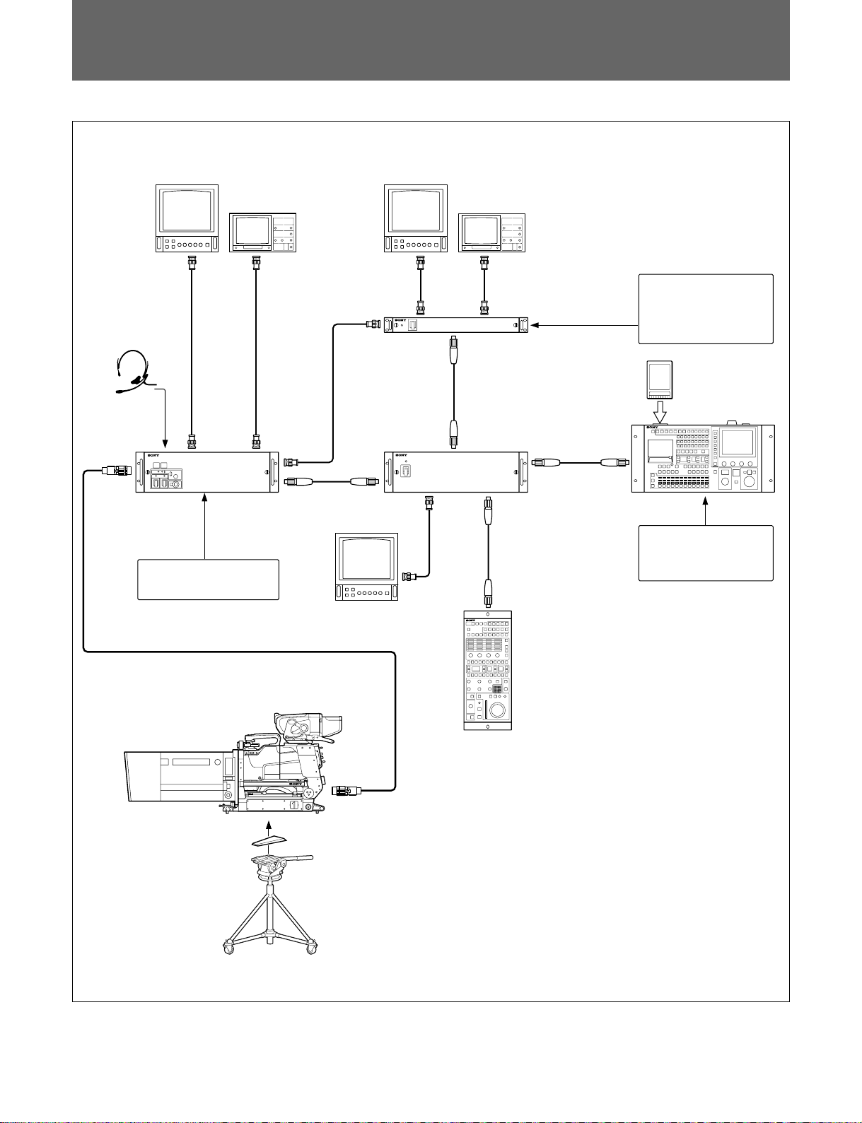
System Configuration Example
Headset
Picture monitor
1
CCU-900/900P
Camera control unit
BKP-9330
Waveform
monitor
Picture monitor
Waveform
monitor
VCS-700
Video selector
CNU-700/500
Camera command
network unit
External control
equipment
IC card
MSU-700A/750
Master setup unit
Switcher
Color video camera
BVP-9500WS/9500WSP/
950/950P
+ CA-950/950P
+ CA-905L
Character monitor
RCP-700-series
Remote control panel
V-wedge shoe
Tripod
7
Page 10
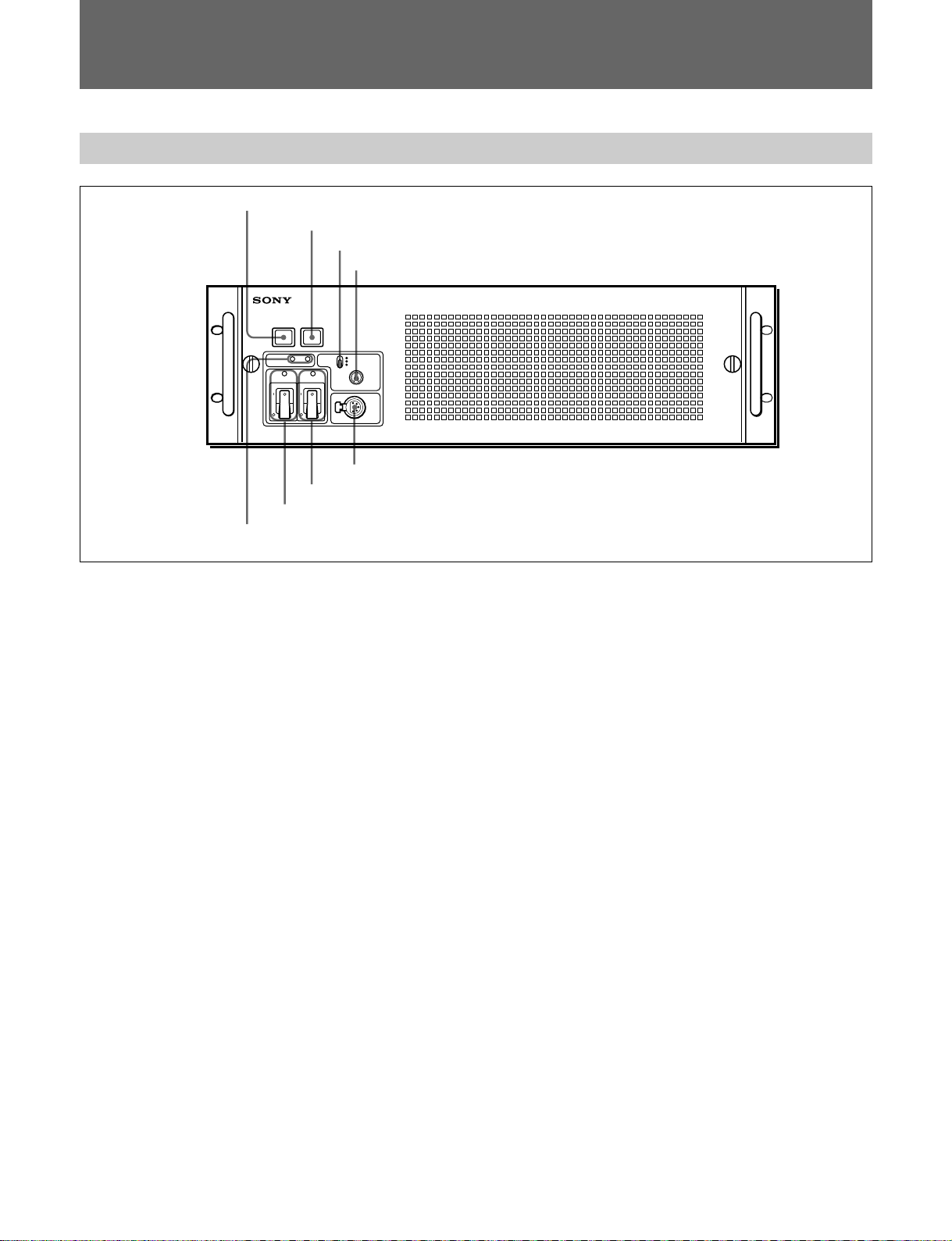
Location and Function of Parts
Front Panel
1 Red tally lamp
2 Green tally lamp
3 MIC switch
4 INTERCOM control
8 INTERCOM connector
7 CAMERA POWER switch and indicator
6 MAIN POWER switch and indicator
5 CABLE ALARM indicator
1 Red tally lamp
Lights when a red tally signal is received. When the
CALL button on the video camera, Master Setup Unit
MSU-700A/750, RCP-700-series Remote Control
Panel, etc. is pressed, this lamp will go out if
previously lit, and light up if previously off. A
supplied number plate can be mounted here.
2 Green tally lamp
Lights when a green tally signal is received. A
supplied number plate can be mounted here.
3 MIC (microphone selection) switch
Used to select the type of headset microphone being
used, or to turn microphone input off.
DYNAMIC: for a dynamic microphone
OFF: turns microphone input off
CARBON: for a carbon microphone
4 INTERCOM (intercom volume adjustment)
control
Adjusts the intercom input level.
5 CABLE ALARM indicator
SHORT: This indicator lights when there is a short
circuit between a power supply line and the sheath
of the optical-fiber cable, or when the two powersupply lines are shorted. When this indicator
lights, the power supply is shut off. (If the
optical-fiber cable is long, this indicator may light
for a few seconds after the main power is turned
on until the short-circuit detection circuitry begins
operating normally. This is not a malfunction.)
OPEN: Lights when there is no camera connected
via an optical-fiber cable to the CAMERA
connector on the rear panel.
The indicator blinks slowly when reception of
light is in WARNING status, and blinks fast when
it is in CARE status.
6 MAIN POWER switch and indicator
Turns on/off the power to the entire system, consisting
of the CCU-900/900P, a video camera, an RCP-700series Remote Control Panel connected via the
REMOTE connector, etc. Setting the switch to the ?
position turns the power on, and setting it to a turns it
off. The indicator is lit when the power supply is on.
7 CAMERA POWER switch and indicator
Turns on/off the power to the camera when the MAIN
POWER switch is on. Setting the switch to the ?
position turns the power on, and setting it to a turns it
off.
When a remote control panel is connected and the
power supply is turned off with the CAM PW button
on the remote control panel, this switch alone cannot
be used to turn on the power of the video camera.
8
Page 11

8 INTERCOM connector (XLR 5-pin)
For connecting a headset. To use a headset with a plug
other than an XLR 5-pin plug, consult a Sony service
representative.
Rear Panel
1 CAMERA connector
2 SDI signal input/output connectors
3 Analog signal input/output connectors
BKP-9330 (optional)
4 - AC IN connector
5 Remote control connectors
6 CHARACTER OUTPUT connector
7 DIGITAL AUDIO connector
8 AUDIO OUTPUT connectors
9 INCOM REMOTE connectors
0 INTERCOM/TALLY/PGM connector
1 CAMERA connector (optical-fiber connector)
For connecting a video camera, using an optical-fiber
cable such as the FC2-PD50/PD250. All video camera
signals, including power supply, control, video, and
audio, are sent and received with an optical-fiber cable.
Note
Dust on the connection surface of the optical-fiber
cable may result in transmission errors. When not
connected, always cover the end with the supplied cap.
9
Page 12

Location and Function of Parts
2 SDI signal input/output connectors
A SERIAL RET INPUT 1 to 4 connectors
B AUX IN connector
1234 1IN OUT 2 3 MONI
SERIAL RET INPUT AUX REFERENCE IN SERIAL OUTPUT
C AUX OUT connector
D REFERENCE IN connectors
E SERIAL OUTPUT 1 to 3 connectors
F SERIAL OUTPUT MONI
connector
A SERIAL RET INPUT 1 to 4 (SDI return video 1,
2, 3, and 4 input) connectors (BNC-type)
Four SDI return video signals are received
independently. The selection of RET 1, 2, 3, or 4 is
made using the return video switch on the camera.
The signals assigned to RET 1, 2, 3, and 4 are selected
using the setup menu of the CCU-900/900P, or using
the MSU-700A/750 Master Setup Unit, from among
the SDI, analog, SDI AUX, and PROMPTER.
B AUX IN (auxiliary input) connector (BNC-type)
For inputting an SDI video signal.
The input signal is output via the AUX OUT
connector. It is also possible to assign the signal to
RET 1, 2, 3, and 4 using the setup menu of the CCU900/900P.
For dual camera operation, the primary and secondary
CCUs are connected using the AUX IN/OUT
connectors mutually.
C AUX OUT (auxiliary output) connector (BNC-
type)
Outputs the signal that is input via the AUX IN
connector.
connector with a 75-ohm terminator.
E SERIAL OUTPUT 1 to 3 connectors (BNC-type)
The signal from the video camera is output as three
SDI signals.
If the BKP-9330 is installed, mixed signal of triplespeed signals sent from the BVP-9500WS/9500WSP
are output through these connectors. Mixing is set to
ON or OFF with the VPR-57 board of this unit or the
MSU-700A/750 Master Setup Unit.
F SERIAL OUTPUT MONI (SDI monitor output)
connector (BNC-type)
The signal from the video camera mixed with the
character signal, skin-tone gate signal, and 4:3 marker
signal is output as an SDI signal.
Mixing is set to ON or OFF with the RCP-700 series or
MSU-700A/750 Master Setup Unit.
D REFERENCE IN (reference input) connectors
(BNC-type)
Used to input a reference signal (sync or VS signal) for
an external sync operation. Terminate the unused
10
Page 13

3 Analog signal input/output connectors
A RET INPUT 1 to 4 connectors
1 2 3 4 IN OUT PIX1WF1 WF2 PIX2
B PROMPTER IN connectors
C PROMPTER OUT connector
D MONITOR OUT WF 1/WF 2 connectors
E MONITOR OUT PIX 1/PIX 2 connectors
F SYNC OUT connector
RET INPUT PROMPTER
A RET INPUT 1 to 4 (return video 1, 2, 3, and 4
input) connectors (BNC-type)
Four analog return video signals are received
independently. The selection of RET 1, 2, 3, or 4 is
made using the return video switch on the camera.
The signals assigned to RET 1, 2, 3, and 4 are selected
using the setup menu of the CCU-900/900P, or using
the MSU-700A/750 Master Setup Unit, from among
SDI, analog, SDI AUX, or PROMPTER.
B PROMPTER IN connectors (BNC-type)
Used for prompter signal input. Terminate the unused
connector with a 75-ohm terminator. An analog signal
of 1.0 Vp-p, 75-ohms is output via the PROMPTER
OUT connector of a video camera with a frequency
bandwidth of 5 MHz, regardless of signal format.
C PROMPTER OUT connector (BNC-type)
Outputs the signals that are input via the PROMPTER
IN connectors of the CCU-900/900P.
These are analog signals of 1.0 Vp-p, 75 ohms.
MONITOR OUT
SYNC OUT
D MONITOR OUT WF 1/WF 2 (waveform
monitor output 1/2) connectors (BNC-type)
Used for outputting a video signal for the waveform
monitor selected with the MONITOR SELECT button
on the RCP-700-series Remote Control Panel or the
WF MONITOR button on the MSU-700A/750 Master
Setup Unit.
For information about these operations, refer to the
Operation Manual supplied with the Master Setup Unit or
Remote Control Panel.
E MONITOR OUT PIX 1/PIX 2 (picture monitor
output 1/2) connectors (BNC-type)
Used for outputting a video signal for a picture
monitor selected with the MONITOR SELECT button
on the RCP-700-series Remote Control Panel, or the
PICTURE MONITOR button on the MSU-700A/750
Master Setup Unit.
For information about these operations, refer to the
Operation Manual supplied with the Master Setup Unit or
Remote Control Panel.
F SYNC OUT (sync signal output) connector
(BNC-type)
Used for outputting a composite sync signal from the
internal sync signal generator.
11
Page 14

Location and Function of Parts
4 -AC IN (AC power supply input) connector
Connect to an AC power supply using the supplied AC
power cord. The power cord is fixed to the CCU-900/
900P using the supplied plug holder.
5 Remote control connectors
A AUX 1/AUX 2 connectors
B MIC REMOTE connector
C WF MODE connector
D WF MODE connector
E RCP/CNU connector
F TRUNK LINE 1/TRUNK LINE 2 connectors
AUX 1 WF MODE
AUX 2 MIC REMOTE
A AUX 1/AUX 2 (auxiliary 1/auxiliary 2)
connectors (D-sub 9-pin, RS-422)
Used to connect the CCU-900/900P and external
equipment via an RS-422 interface.
B MIC REMOTE (microphone remote) connector
(D-sub 15-pin)
Using this connector, the video camera’s microphone
input level may be set from external equipment such as
an audio mixer in five steps (–60, –50, –40, –30, and
–20 dB). When recording, set the volume to an
appropriate level for the audio conditions.
Outputs red and green tally signals.
The microphone input level can be set using switches on an
internal board. For more information on setting the
switches, contact a Sony service representative.
C WF MODE (waveform monitor mode)
connector (D-sub 15-pin)
Used to connect a cable from the appropriate
connector on a waveform monitor when operating the
waveform monitor display using an MSU-700A/750
Master Setup Unit or RCP-700-series Remote Control
Panel. When using a recall-type monitor, preset a
display mode on the waveform monitor, and then
recall the mode externally.
12
TRUNK LINE 1
RCP/CNU
TRUNK LINE 2
D WF MODE (waveform monitor mode output)
connector (4-pin)
Used to connect a cable from the appropriate
connector on a waveform monitor when monitoring a
signal in sequential mode. A sequence signal will be
output when the SEQ button on the RCP-700-series
Remote Control Panel is pressed, allowing
simultaneous monitoring of the R, G, and B signals in
sequential mode.
For information about these operations, refer to the
Operation Manual supplied with the Remote Control Panel.
E RCP/CNU connector (8-pin)
Used to connect to an MSU-700A/750 Master Setup
Unit, CNU-500/700 Camera Command Network Unit,
or RCP-700-series Remote Control Panel using a
CCA-5 Connection Cable. Control signals are sent
and received via this connector. When using an RCP700-series unit, power is also supplied.
F TRUNK LINE 1/TRUNK LINE 2 connectors
(D-sub 9-pin, RS-232C)
Used to connect the CCU-900/900P to the TRACKER
connector (20-pin) on a CA-950/950P Camera Adaptor
via an RS-232C interface. Used mainly for
communication with equipment on the camera side.
The RXD, TXD, RTS, and CTS signals can be
transferred at up to 9600 bps using this connector.
The TRUNK LINE 2 connector is provided for
extension.
Page 15

6 CHARACTER OUTPUT (character signal
output) connector (BNC-type)
Used to output the results of the CCU-900/900P
diagnostic self-test and menu display in black-andwhite analog video format.
7 DIGITAL AUDIO (digital audio signal output)
connector (BNC-type)
Used to output a digital audio signal input to the
camera, or for output of the microphone signal
converted to an AES/EBU-format digital audio signal.
8 AUDIO OUTPUT (audio signal output)
connectors (XLR 3-pin)
Used to output the microphone signal or audio signal
input to the video camera.
9 INCOME REMOTE (intercom remote)
connector (D-sub 25-pin)
Enables remote operation such as muting the intercom,
break-in from the producer or from engineers by
sending signals through this connector from external
control equipments.
Outputs red tally signal, green tally signal, tally call
signal, and camera number signal.
0 INTERCOM/TALLY/PGM (program)
connector (D-sub 25-pin)
Used for input and output of intercom, tally, and
program audio signals. Connect the cable from the
intercom/tally/program connector of the intercom
system.
For information on using with an RTS intercom system,
contact a Sony service representative.
For information on installation, contact a Sony service
representative.
13
Page 16

Location and Function of Parts
BKP-9330 (optional)
A BKP-9330 board can be mounted in the extension
slot of the CCU-900/900P.
For information on installation, contact a Sony service
representative.
1 SERIAL OUTPUT connectors
SS-BSS-A SS-C
SERIAL OUTPUT
1 SERIAL OUTPUT (SS-A, SS-B, SS-C)
connectors (BNC-type)
Outputs a triple-speed signal from the BVP-9500WS/
9500WSP Super Motion Camera via the A, B, and C
connectors as an SDI signal.
For the super-slow output format, it is enabled to set
the output format for an MAV-555 with a BKMA520SS installed or for the SLMS of the EVS.
The output format is changed using switches on the
VPR board.
The rightmost connector is a supplementary connector.
14
Page 17

Internal Board
DPR-69 board
DPR
1 POWER indicator
2 SYSTEM POWER indicator
3 STAIR STEP controls
4 GENLOCK LOCK indicator
5 GENLOCK DIGITAL indicator
POWER
SYSTEM
POWER
STAIR
STEP
LEVEL POSITION
GENLOCK
LOCK
DIGITAL
CHU LOCK
1 POWER indicator
Lights when the board is supplied with proper power.
2 SYSTEM POWER indicator
Lights when the system is supplied with proper power.
3 STAIR STEP controls
For controlling the staircase signal to display the signal
on a waveform monitor in sequential mode.
4 GENLOCK LOCK indicator
Lights when the system is locked with an external sync
signal.
5 GENLOCK DIGITAL indicator
Lights when the sync signal is DIGITAL.
6 CHU LOCK (camera head unit lock) indicator
Lights when communication with the connected
camera is normal.
7 OPTICAL CONDITION (CCU) indicators
Indicate the light level received by the CCU-900/900P.
(0 dBm = 1 mW)
Green lit: normal (optical level not less than –17
dBm)
Yellow lit: normal (optical level between –17 dBm
and –20 dBm)
Red lit: not normal (optical level less than –20 dBm)
OPTICAL CONDITION DUAL MODE
CCU CHU
Note
PRIME SECOND
9 DUAL MODE indicators
8 OPTICAL CONDITION (CHU)
indicators
7 OPTICAL CONDITION (CCU)
indicators
6 CHU LOCK indicator
Clean the optical connector or optical cable if the red
indicator lights.
Cleaning is recommended if the yellow indicator
lights.
For method of cleaning, refer to the maintenance manual.
Reference
The signal level is reduced 0.5 dB for every 1 km of
optical cable.
It is reduced 0.5 dB for every cable connector.
8 OPTICAL CONDITION (CHU) indicators
Indicate the light level received by the Camera. (0
dBm = 1 mW)
Green lit: normal (optical level not less than –17
dBm)
Yellow lit: normal (optical level between –17 dBm
and –20 dBm)
Red lit: not normal (optical level less than –20 dBm)
All indicators off: abnormal communication with the
camera (CHU LOCK indicator also off)
Note
Clean the optical connector or optical cable if the red
indicator lights.
Cleaning is recommended if the yellow indicator
lights.
9 DUAL MODE indicator
Indicates the setting of the CCU when used in dual
camera mode.
15
Page 18

Location and Function of Parts
VPR-57 board
VPR
1 POWER indicator
2 ENABLE indicator
POWER
ENABLE
1 POWER indicator
Lights when the board is supplied with proper power
supply.
2 ENABLE indicator
Lights when the VPR board is in operation.
3 REMOTE/LOCAL switch
For setting the mode, normal (frame interporation) or
triple speed on the VPR board.
REMOTE enables setting from the MSU-700A/750.
LOCAL
REMOTE
3 REMOTE/LOCAL switch
16
Page 19

AT-122 board
AT
1 POWER indicator
2 MIC LEVEL CH1/CH2 controls
3 MENU ON/OFF switch
4 MENU ENTER/CANCEL control
5 ENTER/CANCEL switch
POWER
MIC LEVEL
NORM NORM
CH-1
MIN MIN
CH-2
MENU
ONOFF
ENTER
CANCEL
1 POWER indicator
Lights when the board is supplied with proper power
supply.
2 MIC LEVEL CH1/CH2 (CH1/CH2 microphone
level) controls
For controlling the input level of the MIC connector of
the camera in steps of 10 dBu between –60 dBu and –
20 dBu.
3 MENU ON/OFF switch
For switching ON/OFF the setup and engineering
menus of the CCU.
When the switch is set to ON with the MENU
ENTER/CANCEL control held pressed, the
engineering menu is displayed.
4 MENU ENTER/CANCEL control
For selecting menu items and changing the values.
When pressed, it functions as ENTER.
PGM
INCOM
SELECT
ENG
PRIVATE
PROD
SIDE
RTS
TONE
CANCEL
ENG PROD
0 RTS CANCEL (PROD) control
9 RTS CANCEL (ENG) control
8 SIDE TONE control
7 PGM MIX control
6 INCOM SELECT switch
MIX
7 PGM MIX (program signal mix) control
For controlling the volume of the program that is input
via the INTERCOM connector on the front panel.
8 SIDE TONE control
For controlling the volume of the side tone that is input
via the INTERCOME connector on the front panel.
9 RTS CANCEL (ENG) (engineer line RTS
cancel) control
For controlling the CANCEL level of the ENG line
when the RTS intercom system is used.
0 RTS CANCEL (PROD) (producer line RTS
cancel) control
For controlling the CANCEL level of the PROD line
when the RTS intercom system is used.
5 ENTER/CANCEL switch
For registering or cnaceling the selected item in a
menu operation. Turning the switch to ENTER
enables the same function as pressing the MENU
ENTER/CANCEL control.
6 INCOM SELECT (intercom select) switch
For selectding the intercom line.
ENG: engineer line
PRIVATE: private line
PROD: producer line
17
Page 20

Connections
Digital Video Signal Connections
Other than the optical-fiber cables and AC power cords, all cables are 75-ohm coaxial cables with BNC connectors.
BVP-9500WS/9500WSP/950/950P
+ CA-950/950P
+ CA-905L 1
CCU
Optical-fiber cable
CAMERA
SERIAL RET INPUT 1~4
PROMPTER IN
REFERENCE IN
75-ohm termination
SERIAL OUTPUT 1~3
SERIAL OUTPUT MONI
SYNC OUT
Return video signals
Reference signal
Prompter signal
Component SDI signals
Reference signal
CCU-900/900P 1
PROMPTER IN
BVP-9500WS/9500WSP/950/950P
+ CA-950/950P
+ CA-905L 2
Optical-fiber cable
PROMPTER
Component SDI
signals
75-ohm
termination
CAMERA
INPUT
CHARACTER OUTPUT
SERIAL RET INPUT 1~4
75-ohm
termination
CCU
IN
CHARACTER OUTPUT
Digital Video Routing Switcher
DVS-V1201
REFERENCE IN
75-ohm termination
SERIAL OUTPUT 1~3
SERIAL OUTPUT MONI
RCP/CNU
CCU
SYNC OUT
Camera Command Network
Unit CNU-700
-AC IN
AC power cord
(supplied)
Analog video signal
Return video signals
Reference signal
Component SDI signals
Reference signal
CCU-900/900P 2
-AC IN
AC power cord
(supplied)
Analog video signal
CHARACTER 2
AC power
supply
AC power
supply
Analog video
signal
18
OUTPUT
REF IN
Component SDI signals
Reference signal
REFERENCE
75-ohm termination
SD reference signal
Page 21

Video Signal Connections
Other than the optical-fiber cables and AC power cords, all cables are 75-ohm coaxial cables with BNC connectors.
BVP-9500WS/9500WSP/
950/950P
+ CA-950/950P
+ CA-905L
Optical-fiber cable
CAMERA
RET INPUT 1~4
CCU
SERIAL RET INPUT 1~4
REFERENCE IN
75-ohms termination
SERIAL OUTPUT
SYNC OUT
MONITOR OUT
PIX 1/PIX 2
MONITOR OUT
WF 1/WF 2
Component/composite SDI-RET
signals
Reference signal
Component/composite SDI
signals
Reference signal
CCU-900/900P
Picture monitor output
Waveform monitor output
Analog return video signals
Note
The input signal must be synchronized with the clock of the CCU-900/
900P.
19
Page 22

Connections
Connections for the Dual Camera Operation
Other than the optical-fiber cables, all cables are 75-ohm coaxial cables with BNC connectors.
Primary camera
BVP-9500WS/9500WSP/950/950P 1
Secondary CCU
CA-950/950P
Optical-fiber cable
CCU-900/900P 1
Serial
OUT
Video signal
Serial
Secondary camera
BVP-9500WS/9500WSP/
950/950P 2
Serial
IN
(Coaxial cable with
BNC connector)
IN
Serial
OUT
CA-950/950P
External power supply
SDI AUX OUT SDI AUX IN
Video signalReturn video signal
Return video signal
(Coaxial cable with
BNC connector)
REFERENCE
IN
••••
••
•
••
••
•
••••••
RCP-700-series
Remote Control
Panel
SDI AUX IN SDI AUX OUT
Secondary CCU
CCU-900/900P 2
REFERENCE
IN
Reference signal
••••
••
•
••
••
•
••••••
RCP-700-series
Remote Control
Panel
Notes
•The primary system and the secondary system must be gen-locked.
•If the BVP-9500WS/9500WSP is operated at triple speed, dual camera
operation is released, and the secondary system cannot be used.
20
Page 23

Connections for a Super-Motion Camera (with the BKP-9330)
Other than the optical-fiber cables, all cables are 75-ohm coaxial cables with BNC connectors.
BVP-9500WS/9500WSP
CA-950/950P
CCU-900/900P + BKP-9330
Optical-fiber cable
SS-A SS-B SS-C
MAV-555
+
BKMA-520SS
Operation mode of the BVP-9500WS/9500WSP, normal speed (×1) or
triple speed (×3), can be selected via the INCOM REMOTE connector on
the rear panel. To select the operation mode on the CCU-900/900P, set the
signal level at pin 23 of the INCOM REMOTE connector to L. Then the
operation mode, normal or triple, can be selected via pin 20 of the INCOM
REMOTE connector as shown in the table below. In this case, the
selection is enabled on the CCU only.
••••
••
•
••
••
•
••••••
RCP-700-series
Remote Control
Panel
INCOM REMOTE Operation mode of the
pin 20 (×1/×3) BVP-9500WS/9500WSP
H (open) ×1
L ×3
21
Page 24

Connections
Connections for Control, Intercom, Tally, and Audio Signals
An configuration example is shown in the figure on the next page.
Selecting a waveform monitor
The waveform monitor to be connected to the D-sub 15-pin WF MODE
connector of the CCU-900/900P or to the WF MODE connector on the
CNU-700 Camera Command Network Unit is a recall type monitor. With
a recall-type monitor, the desired display mode can first be set up on the
waveform monitor (preset), and the mode can then be selected externally
(recall) with the monitor select buttons on the MSU-700A/750 or on the
RCP-700-series unit.
The display mode and the monitor select button have the following
relations:
Display mode Monitor select buttons
PRESET 1 R
PRESET 2 G
PRESET 3 B
PRESET 4 SEQ or R + G + B
PRESET 5 ENC
PRESET 6 R + B
PRESET 7 R + G
PRESET 8 G + B
Using DVS-V1201 SD Digital Video Routing Switchers in a
cascade configuration
Set REMOTE 2 unit address switch “5” of the DVS-V1201 SD Digital
Video Routing Switcher to ON and all others to OFF. When connecting
DVS-V1201 SD Digital Video Routing Switchers in a cascade
configuration to be used with 13 or more cameras, set unit address switch
“6” of the second unit to ON and the others to OFF.
22
Page 25

The required cables are 1 audio cables with XLR 3-pin plugs, 2 D-sub 9-pin remote cables, 3 CCA-5 cables, and 4 75-ohm
coaxial cables with BNC connectors.
For details on cables without number labels, refer to the Service Manual or contact a Sony service representative.
CCU-900/900P 1
INTERCOM
/TALLY
Intercom/program audio/tally
Intercom control
/PGM
INCOM
REMOTE
Audio output
Digital audio output
Waveform monitor control
Microphone control and tally
Waveform monitor SEQ control
Intercom/program audio/tally
Audio output
Digital audio output
Waveform monitor control
Microphone control and tally
CCU1
CCU2 VCS
1
4
INTERCOM
/TALLY
/PGM
INCOM
REMOTE
1
4
CNU-700
AUDIO OUTPUT
DIGITAL AUDIO
AUDIO OUTPUT
DIGITAL AUDIO
3
WF MODE
MIC REMOTE
WF MODE
WF MODE
MIC REMOTE
VCS-700
RCP/CNU
RCP/CNU
3
3
CCU-900/900P 2
REMOTE
WF MODE
Waveform monitor control
CCU/CNU
Switcher
RCP-740/741 1
PREVIEW
RCP1 RCP2 RS-232C
33
CCU/CNU
RCP-740/741 2
2
MSU
MSU-700A/750
Remote2
Remote2
REMOTE1
2
3
CCU/CNU
MP-1007A
DVS-V1201
23
Page 26

Self-Diagnosis
With the RCP-700-series Remote Control Panel
connected, the results of system diagnosis of the
internal boards of the CCU-900/900P can be displayed
on the monitor.
Self-diagnosis of the camera system
System diagnosis display of the camera system
comprises three pages.
System Diag 1/3
*System Diag 1/3*
Optical RX condition
CAMERA OK
CCU OK
Optical TX condition
EMERGENCY
Fan Power OK
Timer 10H
Optical RX condition: condition of optical reception
CAMERA: condition of a camera
CCU: condition of a CCU
System Diag 2/3
*System Diag 2/3*
DUAL Mode OFF
CAMERA Cable Open
Data - Power OFF
Sense NG
RCP/CNU Cable Connect
Data OK
Power OK
DUAL Mode: Displays the setting of dual camera
mode
CAMERA Cable: Status of connection of the camera
cable
CAMERA Data: Existence of data from the camera
CAMERA Power: Status of power supply to the
camera
CAMERA Sense: Status of connection to the CHU
RCP/CNU Cable: Status of cable connection to the
RCP/CNU connector
RCP/CNU Data: Existence of data from the RCP/
CNU connector
RCP/CNU Power: Status of power supply to the RCP/
CNU connector
System Diag 3/3
The display shows the following levels of optical
reception.
Optical reception [dBm] LED display CHARA display
–7.5 Green OK
–10 Green OK
–15 Green OK
–17 Yellow CARE
–20 Red WARN
–25 Red WARN
SYNC ERR Red NG
Optical TX Condition: Condition of optical reception
Fan Power: Condition of fans of the power block and
rear panel
Timer: Duration of power supply to the AT board
*System Diag 3/3*
Intercom
CCU Private
CAMERA CH1 ENG
MIC ON
CH2 ENG
MIC ON
CAMERA MIC Gain
CH1 60dB Local
CH2 60dB Local
Intercom CCU: Setting of the CCU intercom
Intercom CAMERA CH1: Status of intercom 1 of the
camera
Intercom CAMERA CH1 MIC: Status of the
microphone of intercom 1 of the camera
Intercom CAMERA CH2: Status of intercom 2 of the
camera
Intercom CAMERA CH2 MIC: Status of the
microphone of intercom 2 of the camera
CAMERA MIC Gain: Status of gain and control of
the microphone circuit of the camera
24
Page 27

Self-diagnosis result for internal boards of
the CCU-900/900P
The self-diagnosis results for the internal boards of the
CCU-900/900P is displayed by pressing the
CHARACTER button of the RCP-700-series Remote
Control Panel when the third page of self-diagnosis
display of the camera system is on screen.
The diagnosis results for each board will be
successively displayed by further pressing the
CHARACTER button.
DPR Board
*DPR Diagnosis*
POWER OK
LSI Condition OK
Reference REF
Reference Phase Lock
CAMERA Phase Lock
CAMERA LINK LINK
POWER: Operational status of the board regulator
LSI Condition: Setting status of the LSI
Reference: Reference signal source
Reference Phase: State of lock to the reference signal
CAMERA Phase: State of lock phase of the camera
signals
CAMERA LINK: Linkage status of camera command
AT Board
*AT Diagnosis*
POWER OK
Command CAMERA OK
RCP/CNU OK
CAMERA CONNECT OK
CAMERA Power OK
Intercom Private
PGM Input Analog
MIC SERIAL
Gain CH1 60
CH2 60
dB Local
dB Local
Command RCP/CNU: Linkage status with the RCP-
700-series unit or the CNU-700/500
CAMERA CONNECT: Detection of connection with
the camera
CAMERA Power: Detection of power supply to the
camera
Intercom: Setting of the intercom switch
PGM Input: Input condition of the program
MIC Gain: Setting of microphone gain and control
SDI Board
*SDI Diagnosis*
POWER OK
LSI Condition OK
SERIAL OUT OK
SERIAL MONI OUT OK
SERIAL AUX OUT OK
SERIAL RET1 IN
SERIAL RET2 IN
SERIAL RET3 NO
SERIAL RET4 NO
SERIAL AUX IN
POWER: Operational status of the board regulator
LSI Condition: Setting status of the LSI
SERIAL OUT: PLL output status of the SDI signal
SERIAL MONI OUT: Output status of the SDI
picture monitor signal
SERIAL AUX OUT: Output statusn of the SDI AUX
signal
SERIAL RET1: Existence of input from the SDI
RET1 signal
SERIAL RET2: Existence of input from the SDI
RET2 signal
SERIAL RET3: Existence of input from the SDI
RET3 signal
SERIAL RET4: Existence of input from the SDI
RET4 signal
SERIAL AUX: Existence of input from the SDI AUX
signal
POWER: Operational status of the board regulator
Command CAMERA: Linkage status with the
camera
25
Page 28

Self-Diagnosis
IF Board
*IF Diagnosis*
POWER OK
LSI Condition OK
Active
RET A-RET1 IN
AUX AUX IN
PORMPT PORMPT
POWER: Operational status of the board regulator
LSI Condition: Setting status of the LSI
Active: Existence of an active input route
RET: Active RET signal route
AUX: Active AUX signal route
PROMPT: Active PROMPTER signal route
VPR Board
DIF Board
*DIF Diagnosis*
POWER OK
LSI Condition OK
SS-A OUT OK
SS-B OUT OK
SS-C OUT OK
POWER: Operational status of the board regulator
LSI Condition: Setting status of LSI
SS-A OUT: Output status of SDI-A signal
SS-B OUT: Output statusn of SDI-B signal
SS-C OUT: Output status of SDI-C signal
This display does not appear if no DIF-38 board is
installed.
CAMERA Diagnosis
*VPR Diagnosis*x1
POWER OK
LSI Condition OK
Frame Interpolation
DISC Mode MAV
POWER: Operational status of the board regulator
REMOTE:OFF
LSI Condition: Setting status of the LSI
Frame Interpolation: Setting status of output picture
composition on the VPR board
DISC Mode: Setting status of output format of the SS-
A/SS-B/SS-C connectors
This display does not appear if no VPR-57 board is
installed.
A maximum of 3 pages of self-diagnosis, depending
on the number of boards installed is displayed for the
boards not supplied.
*CAMERA Diagnosis*
ALL OK
The board DIAG display transmitted by the DIAG
command is displayed as is.
ROM Version
*ROM Version*
CAM 1.01
1999.09.10
CCU 1.01
1999.09.10
RCP 1.01
1999.09.10
26
CAM: Displays the ROM version of the camera head
CCU: Displays the ROM version of CCU
RCP: Displays the ROM version of RCP
Page 29

Specifications
CCU-900/900P
General
Power supply 100/110-120/220-240 V AC,
50/60 Hz
(To change to a different power
supply, contact a Sony service
representative.)
Current consumption
5 A (at 100 V AC, entire system
active)
Peak inrush current
(1) Power ON, current probe method: 80 A (240 V)
60 A (100 V)
(2) Hot switching inrush current, measured in
accordance with European standard
EN55103-1: 10 A (230 V)
Operating temperature
5°C to 40°C (41°F to 104°F)
Storage temperature
–20°C to +60°C (–4°F to +140°F)
Humidity no condensation
Dimensions (w/h/d)
Approx. 424 × 133 × 460 mm
3
(16
/4 in × 51/4 × 181/8 inches)
Mass Approx. 20 kg (44 lb 1 oz)
Dimensions
Environment for installing and using the
equipment
• Avoid rooms of high temperature or placing near a
heat source.
• Avoid a place with strong electric or magnetic field.
• Set in a cool, dry place.
• Keep out of direct sunlight or other strong light.
Input/Output connectors
CAMERA Optical-fiber connector (1)
1.08Gb/s SDI × 2, 240 V
AC power supply
INCOM/TALLY/PGM
D-sub 25-pin connector (1)
• INCOM-4W, 2 systems (PD/
ENG), 0 dB
• PGM, 2 systems, 0 dB/–20 dB
• TALLY (R, G), TALLY contact
INCOM REMOTE
D-sub 25-pin (1)
RCP/CNU 8-pin multiconnector (1)
TRUNK LINE 1/TRUNK LINE 2
D-sub 9-pin, female (1)
RS-232C, for CHU transmission
AUX 1/AUX 2 D-sub 9-pin, female (1)
RS-422, for CCU system expansion
424
465
481
133
57.2
(unit: mm)
Input connectors
AC IN 100 to 120, 220 to 240 V AC
switchable
PROMPTER IN BNC-type (1), with loop-through
output, SMPTE-292M analog
460
SERIAL RET INPUT
REFERENCE IN BNC-type (1), with loop-through
RET INPUT BNC-type (4), 1.0 Vp-p, 75 ohms,
AUX IN BNC-type (1)
signal,
1.0 Vp-p, 75-ohms
BNC-type (4), SMPTE-259M,
0.8 Vp-p, 75 ohms,
270Mb/s bit rate
output, composite SYNC/VS
analog signal
SDI video signal
0.8 Vp-p, 75 ohms,
270Mb/s bit rate
27
Page 30

Specifications
Output connectors
AUDIO OUT XLR 3-pin, male (2),
0 dBs/–20 dBs
CHARACTER BNC-type (1), 525 black and white
210 mVp-p (characters)
300 mVp-p (sync)
MIC REMOTE D-sub 15-pin, female (1)
WF MODE D-sub 15-pin, female (1)
SERIAL OUTPUT
BNC-type (4), SMPTE-259M,
0.8 Vp-p, 75 ohms,
270Mb/s bit rate
SYNC OUT BNC-type (1), composite sync,
0.286 Vp-p, 75 ohms
MONITOR OUT PIX 1/PIX 2
BNC-type (1), 1.0 Vp-p, 75 ohms,
R/G/B/ENC
MONITOR OUT WF 1/WF 2
BNC-type (1), 1.0 Vp-p, 75 ohms,
R/G/B/ENC/SEQ
WF MODE 4-pin multiconnector (1)
stairstep
AUX OUT BNC-type (1)
SDI signal, 0.8 Vp-p, 75 ohms,
270Mbps bit rate
PROMPTER OUT BNC-type (1)
1.0 Vp-p, 75 ohms
SERIAL OUTPUT MONI
BNC-type (1)
SDI signal, 0.8 Vp-p, 75 ohms,
270Mbps bit rate
DIGITAL AUDIO BNC-type (1)
AES/EBU format
CCA-5-10 Connection Cable (10 meter/33 feet)
BKP-7900 Expansion Board
BKP-9330 Optional Board
Connectors for optical/electric composite cables:
•LEMO(R) PUW.3K.93C.TLCC96
(to the “CAMERA” connector on CCU)
•LEMO(R) FUW.3K.93C.TLMC96
(to the “CCU” connector on CAMERA)
Caution on the optical/electric composite cable:
For connection between the camera control unit and a
camera, be sure to use an optical/electric signal
composite cable with the connectors specified in this
manual in order to comply with the limits for EMC
regulations.
Related equipment
BVP-9500WS/9500WSP Super Motion Camera
BVP-950/950P Color Video Camera
CA-950/950P Camera Adapter
CA-905L Studio Build-up Unit
RCP-700-series Remote Control Panel
MSU-700A/750 Master Setup Unit
VCS-700 Video Selector
CNU-700/500 Camera Command Network Unit
MAV-555 Multi Access Video Disk Recorder
BKMA-520SS Super Motion Input Board
Design and specifications are subject to change
without notice.
Supplied accessories
AC power cord (1)
Power cord plug holder (1)
4-pin connector (1)
Number plates (1 set)
Fuses (1 set)
Operation manual (1)
Maintenance manual (1)
Voltage indication label (1)
Optional accessories
FC2-PD50 Optical Fiber Cable (50 meter/164 feet)
FC2-PD250 Optical Fiber Cable (250 meter/820 feet)
CCA-5-3 Connection Cable (3 meter/10 feet)
28
BKP-9330 (optional)
Operating temperature
5°C to 40°C (41°F to 104°F)
Storage temperature
–20°C to +60°C (–4°F to +140°F)
Dimensions (w/h/d)
VPR-57 board: Approx. 230 × 17 × 309 mm
DIR-38 board: Approx. 213 × 28 × 94 mm
Mass Approx. 1.4 kg (2 lb 5 oz)
SERIAL OUT BNC-type, SMPTE-259M,
Design and specifications are subject to change
without notice.
1
/8 × 11/16 × 121/4 inches)
(9
1
/2 × 11/8 × 33/4 inches)
(8
270Mb/s bit rate
Page 31

The material contained in this manual consists of
information that is the property of Sony Corporation and is
intended solely for use by the purchasers of the equipment
described in this manual.
Sony Corporation expressly prohibits the duplication of any
portion of this manual or the use thereof for any purpose
other than the operation or maintenance of the equipment
described in this manual without the express written
permission of Sony Corporation.
Le matériel contenu dans ce manuel consiste en
informations qui sont la propriété de Sony Corporation et
sont destinées exclusivement à l’usage des acquéreurs de
l’équipement décrit dans ce manuel.
Sony Corporation interdit formellement la copie de quelque
partie que ce soit de ce manuel ou son emploi pour tout
autre but que des opérations ou entretiens de l’équipement
à moins d’une permission écrite de Sony Corporation.
Das in dieser Anleitung enthaltene Material besteht aus
Informationen, die Eigentum der Sony Corporation sind,
und ausschließlich zum Gebrauch durch den Käufer der in
dieser Anleitung beschriebenen Ausrüstung bestimmt sind.
Die Sony Corporation untersagt ausdrücklich die
Vervielfältigung jeglicher Teile dieser Anleitung oder den
Gebrauch derselben für irgendeinen anderen Zweck als die
Bedienung oder Wartung der in dieser Anleitung
beschriebenen Ausrüstung ohne ausdrückliche schriftliche
Erlaubnis der Sony Corporation.
Page 32

CCU-900/900P(UC)
3-204-460-04(1)
Sony Corporation
B&P Company
Printed in Belgium
2002.10.08
2000
 Loading...