

Sony CCD-TR416PK, CCD-TR416, CCD-TRV16, CCD-TRV16PK, CCD-TRV36 Service Manual
...
CCD-TR315/TR416/TR416PK/TR516/TR516PK/TR716
CCD-TRV16/TRV16PK/TRV36/TRV36PK/TRV43/
TRV46/TRV46PK
SERVICE MANUAL
MICROFILM
SPECIFICATIONS
US Model
Canadian Model
CCD-TR416/TR516/TR716
CCD-TRV16/TRV36/TRV43/TRV46
E Model
CCD-TR315/TR416PK/TR516PK
CCD-TRV16/TRV16PK/TRV36PK/
TRV46/TRV46PK
Hong Kong Model
CCD-TRV16/TRV46
Taiwan Model
CCD-TRV16
Brazilian Model
CCD-TR315/TR416
CCD-TRV16
h
VIDEO CAMERA RECORDER
— Continued on next page —
Video camera recorder
System
Video recording system
2 Rotary heads
Helical scanning FM system
Audio recording system
Rotary heads, FM system
Video signal
NTSC color, EIA standards
Usable cassette
8mm video format cassette
CCD-TR315/TR416/TR416PK
CCD-TRV16/TRV16PK
: standard 8
CCD-TR516/TR516PK/TR716
CCD-TRV36/TRV36PK/TRV43/TRV46/
TRV46PK : Hi8
Recording / Playback time
(using 120 min. cassette)
SP mode: 2 hours
LP mode: 4 hours
Fastforward/rewind time
(using 120 min. cassette)
Approx. 5 min.
Image device
1/4 inch CCD (Charge Coupled Device)
CCD-TR315/TR416/TR416PK/TR516/
TR516PK
CCD-TRV16/TRV16PK/TRV36/
TRV36PK : Approx. 270,000 pixels
(Effective : approx 250,000 pixels)
CCD-TR716
CCD-TRV34/TRV46/TRV46PK :
Approx. 320,000 pixels
(Effective : approx 200,000 pixels)
Viewfinder
Electronic viewfinder
CCD-TR315/TRV series : Monochrome
CCD-TR416/TR416PK/TR516/
TR516PK/TR716 : Color
Lens
Combined power zoom lens
Filter diameter 1 7/16 in. (37 mm)
CCD-TR315/TR416:US,CND
CCD-TRV16/TRV16PK
: 18 x (Optical), 180 x (Digital)
CCD-TR416:BR/TR416PK
: 18 x (Optical), 220 x (Digital)
CCD-TR516/TR516PK/TR716
CCD-TRV36/TRV36PK/TRV43/TRV46/
TRV46PK
: 18 x (Optical), 330 x (Digital)
Focal distance
3/16 - 8 in. (4.1 - 37.8 mm)
When converted to a 35 mm still camera
CCD-TR315/TR416/TR416PK/TR516/
TR516PK
CCD-TRV16/TRV16PK/TRV36/
TRV36PK
: 1 9/16 - 28 in. (39.4 - 709 mm)
CCD-TR715
CCD-TRV43/TRV46/TRV46PK
: 1 7/8 - 33 1/2 in. (47.2 - 850 mm)
RMT-708
Photo : CCD-TR516
Photo : CCD-TRV46
H
VIDEO CAMERA RECORDER
CCD-TR315/TR416/TR416PK
CCD-TRV16/TRV16PK
CCD-TR516/TR516PK/TR716
CCD-TRV36/TRV36PK/TRV43/TRV46/TRV46PK
Color temperature
Auto
Minimum illumination
0.4 lux at F 1.4
0 lux (in NightShot mode)*
Illumination range
0.4 lux to 100,000 lux
Recommended illumination
More than 100 lux
* Object invisible for the dark can be
shot with infrared lighting.
LCD screen (TRV series only)
Picture
2.5 inches measured diagonally
2 x 1 1/2 in.(50.3 x 37.4 mm)
On-screen display
TN LCD/TFT active matrix method
Total dot number
61,380 (279 x 220)
For MECHANISM ADJUSTMENTS, refer to
the “8mm Video MECHANICAL ADJUSTMENT
MANUAL VII” (9-973-801-11).
B MECHANISM
NTSC
Ver 1.0 1999.01

– 2 –
SAFETY-RELATED COMPONENT WARNING !!
COMPONENTS IDENTIFIED BY MARK ! OR DOTTED LINE WITH
MARK ! ON THE SCHEMATIC DIAGRAMS AND IN THE PARTS
LIST ARE CRITICAL TO SAFE OPERATION. REPLACE THESE
COMPONENTS WITH SONY PARTS WHOSE PART NUMBERS
APPEAR AS SHOWN IN THIS MANUAL OR IN SUPPLEMENTS
PUBLISHED BY SONY.
1. Check the area of your repair for unsoldered or poorly-soldered
connections. Check the entire board surface for solder splashes
and bridges.
2. Check the interboard wiring to ensure that no wires are “pinched”
or contact high-wattage resistors.
3. Look for unauthorized replacement parts, particularly transistors,
that were installed during a previous repair. Point them out to
the customer and recommend their replacement.
4. Look for parts which, though functioning, show obvious signs
of deterioration. Point them out to the customer and recommend
their replacement.
5. Check the B+ voltage to see it is at the values specified.
6. Flexible Circuit board Repairing
• Keep the temperature of the soldering iron around 270°C during
repairing.
• Do not touch the soldering iron on the same conductor of the
circuit board (within 3 times).
• Be careful not to apply force on the conductor when soldering
or unsoldering.
SAFETY CHECK-OUT
After correcting the original service problem, perform the following
safety checks before releasing the set to the customer:
ATTENTION AU COMPOSANT AYANT RAPPORT
À LA SÉCURITÉ!!
LES COMPOSANTS IDENTIFIÉS P AR UNE MARQUE ! SUR LES
DIAGRAMMES SCHÉMA TIQUES ET LA LISTE DES PIÉCES SONT
CRITIQUES POUR LA SÉCURITÉ DE FONCTIONNEMENT. NE
REMPLACER CES COMPOSANTS QUE PAR DES PIÉCES SONY
DONT LES NUMÉROS SONT DONNÉS DANS CE MANUEL OU
DANS LES SUPPLÉMENTS PUBLIÉS PAR SONY.
Input and output connectors
Video output
Phono jack, 1 Vp-p, 75 ohms, unbalanced
Audio output
Monaural, Phone jack, 327 mV
(at output impedance 47 kilohms)
impedance less than 2.2 kilohms
RFU DC OUT
Special minijack, DC 5V
Earphone jack (TRV series only)
Monaural minijack (ø 3.5 mm)
LANC control jack
Stereo mini-minijack (ø 2.5 mm)
MIC jack
Mini jack, 0.388mV low impedance with
2.5 to 3.0 V DC, output impedance 6.8
kilohms (ø 3.5 mm) : Monaural type
Speaker (TRV series only)
Dynamic speaker
General
Power requirements
7.2 V (battery pack)
8.4 V (AC power adaptor)
Averege power consumption(when
using the battery pack)
During camera recording
CCD-TR416/TR416PK/TR516/
TR516PK : 2.4 W
CCD-TR315/TR716 : 2.5 W
During camera recording using
LCD
CCD-TRV16/TRV16PK/TRV36/
TRV36PK : 3.1 W
CCD-TRV43/TRV46/TRV46PK : 3.2 W
Viewfinder
CCD-TRV16/TRV16PK/TRV36/
TRV36PK : 2.5 W
CCD-TRV43/TRV46/TRV46PK : 2.6 W
Operating temperature
32°FC to 104°F (C0°C to 40°C)
Storage temperature
-4°FC to 140°F (-20°C to +60°C)
Dimentions (Approx.)
4 1/4 x 4 1/4 x 7 5/8 in.
107 x 107 x 193 mm)(w/h/d)
Mass (Approx.)
CCD-TR315/TR716 : 1 lb 11 oz (790 g)
CCD-TR416/TR416PK/TR516/
TR516PK : 1 lb 11 oz (780 g)
CCD-TRV16/TRV16PK/TRV36/
TRV36PK : 1 lb 14 oz (870 g)
CCD-TRV43/TRV46/TRV46PK
: 1 lb 15 oz (880 g)
excluding the battery pack, lithium
battery, cassette and shoulder strap
2 lb 3 oz (1 kg)
including the battery pack NP-F330,
lithium battery CR2025, cassette and
shoulder strap
Microphone
Monaural type
Supplied accessories
See page 4.
AC power adaptor
Power requirements
100 -240 V AC, 50/60 Hz
Power consumption
23 W
Output voltage
DC OUT: 8.4 V, 1.5 A in operating mode
Operating temperature
32°F to 104°F(0°C to 40°C)
Storage temperature
-4°F to +140°F(-20°C to +60°C)
Dimentions (Approx.)
5 x 1 9/16 x 2 1/2 in. (125 x 39 x 62
mm)(w/h/d) excluding projecting parts
Mass (Approx.)
9.8 oz (280 g) excluding power cord
Design and specifications are subject to
change without notice.
• Abbreviation
Canadian model is abbreviated as CND.
Brazilian model is abbreviated as BR.
– 3 –
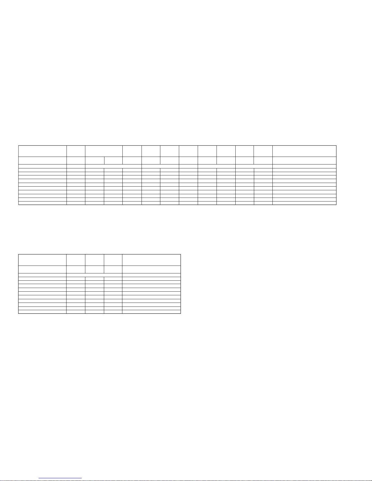
Table for difference of function
CCDTRV36PK
E
B/W
¬
¬
G
330X
¬
510
G
G
2.5 inch
CCDTRV16
US,CND,E,
HK,BR,TW
B/W
G
G
¬
180X
G
510
G
G
2.5 inch
CCDTR516PK
E
Color
¬
¬
G
330X
¬
510
G
G
G
CCDTR416
US,CND
Color
G
G
¬
180X
G
510
G
G
G
CCDTR315
E,BR
B/W
G
G
¬
180X
G
510
G
G
G
CCDTRV16PK
E
B/W
G
G
¬
180X
G
510
G
G
2.5 inch
CCDTR716
US,CND
Color
¬
¬
G
330X
¬
510P
¬
G
G
CCDTR516
US,CND
Color
¬
¬
G
330X
¬
510
G
G
G
Model
Destination
Classification
View finder
Remote commander (RMT-708)
Hi8
Standard 8
Lens (Digital ZOOM)
Video light
CCD
Steadyshot
Laser Link
LCD panel
BR
Color
G
G
¬
220X
G
510
G
G
G
CCDTR416PK
E
Color
G
G
¬
220X
G
510
G
G
G
Remark
¬ : with SE-80/81board SE451,452,IC451
¬ : with VC-215board IC751
2.5 inch : TRV series only
TYPE E TYPE G TYPE C TYPE D TYPE F TYPE A
CCDTRV36
US,CND
B/W
¬
¬
G
330X
¬
510
G
G
2.5 inch
CCDTRV46
US,CND,E,
HK
B/W
¬
¬
G
330x
¬
510P
¬
¬
2.5 inch
CCDTRV43
US,CND
B/W
¬
¬
G
330x
¬
510P
¬
¬
2.5 inch
Model
Destination
Classification
View finder
Remote commander (RMT-708)
Hi8
Standard 8
Lens (Digital ZOOM)
Video light
CCD
Steadyshot
Laser Link
LCD panel
CCDTRV46PK
E
B/W
¬
¬
G
330x
¬
510P
¬
¬
2.5 inch
Remark
¬ : with SE-80/81board SE451,452,IC451
¬ : with VC-215board IC751
2.5 inch : TRV series only
TYPE B
• Abbreviation
Canadian model is abbreviated as CND.
Brazilian model is abbreviated as BR.
Hong Kong model is abbreviated as HK.
Taiwan model is abbreviated as TW.
– 4 –
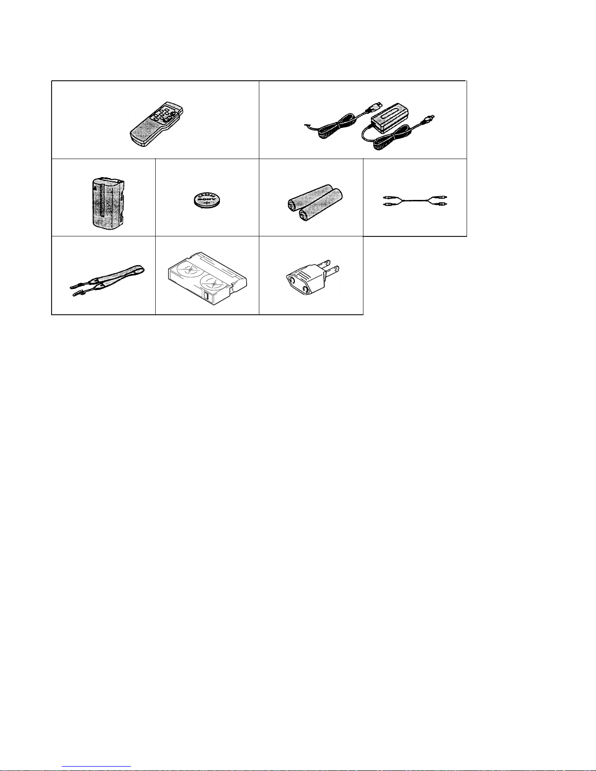
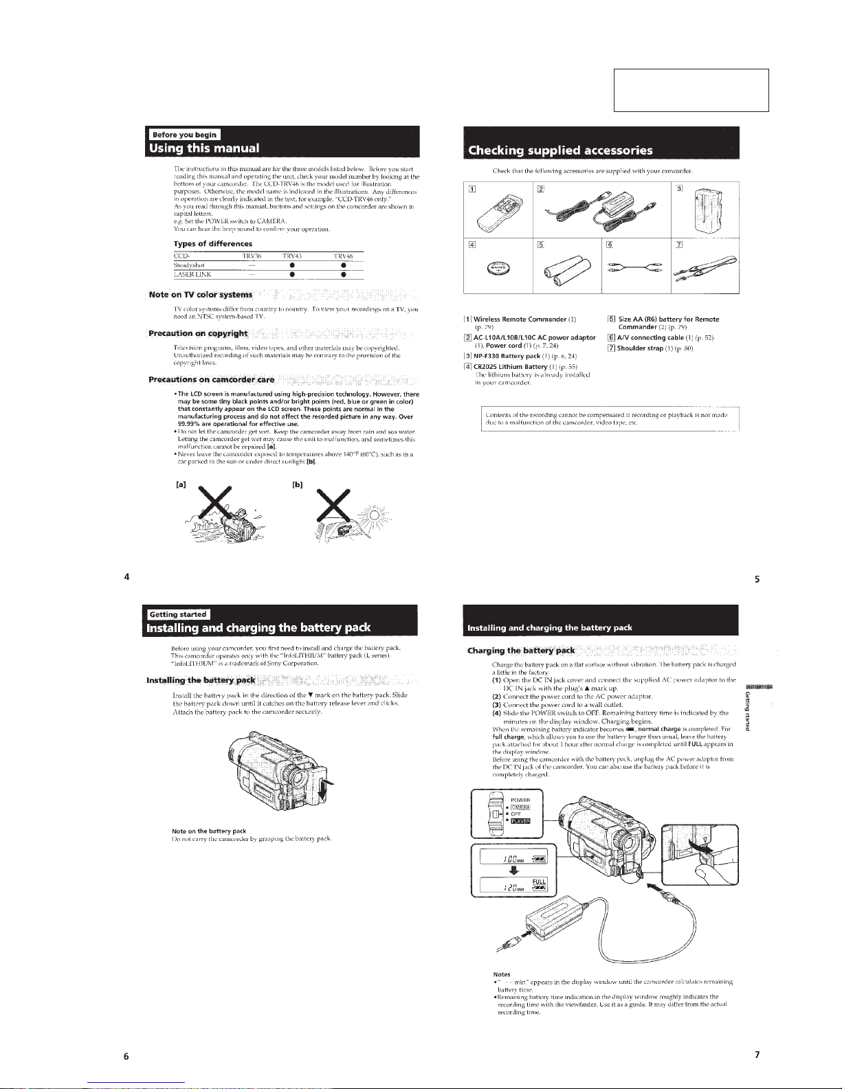
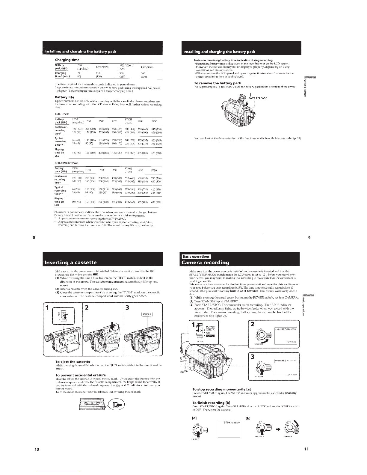
Supplied accessories
1 RMT-708 Wireless Remote Commander (1)
CCD-TR516/TR516PK/TR716
CCD-TRV36/TRV36PK/TRV43/TRV46/TRV46PK
2 AC-L10A/L10B/L10C AC power adaptor
3 NP-F330 Battery pack (1)
4 CR2025 Lithium Battery (1)
The lithium battery is already installed in your camcorder.
5 Size AA (R6) battery for Remote Commander
(2)
CCD-TR516/TR516PK/TR716
CCD-TRV36/TRV36PK/TRV43/TRV46/TRV46PK
6 A / V connecting cable (1)
1
4
8
7
3
2
5
• Abbreviation
Brazilian model is abbreviated as BR.
Hong Kong model is abbreviated as HK.
Taiwan model is abbreviated as TW.
6
7 Shoulder strap (1)
8 Video P6-15P HB tape
CCD-TR416: US/TR516: US/TR716:US
CCD-TRV16:US/TRV36:US/TRV43:US/TRV46:US
9 2 pin conversion adaptor (1)
CCD-TR315//TR416PK/TR516PK
CCD-TRV16:E,BR,HK,TW/TRV16PK/TRV36PK/
TRV46:E,HK/TRV46PK
9

– 5 –
Battery terminal
‘
DC IN terminal
Battery SIG terminal
Battery switch
Battery terminal
’
SERVICE NOTE
6
Pull the timing belt in the direction of arrow A
with a pinsette while pressing the cassette lid
(take care not to damage) to adjust the
bending of a tape.
7
Let go your hold the cassette
lid and rise the cassette
compartment to take out a cassette.
A
Pinsette
Timing belt
Press the cassette lid not to rise the
cassette compartment
+
–
[DC power supply]
(+5V)
Loading motor
Adjust the bending of a tape
Timing belt
1 Refer to 2-1. to remove the front panel block.
2 Refer to 2-4. to remove the cabinet (R) assembly.
3 Refer to 2-6. to remove the battery panel block.
4 Refer to 2-7. to remove the cabinet (L) block.
5 Add +5V from the DC POWER SUPPLY and unload with a
pressing the cassette lid.
2. TO TAKE OUT A CASSETTE WHEN NOT EJECT (FORCE EJECT)
1. POWER SUPPLY DURING REPAIRS
In this unit, about 10 seconds after power is supplied (8.4V) to the
battery terminal using the service power cord (J-6082-223-A), the
power is shut off so that the unit cannot operate.
This following three methods are available to prevent this. Take
note of which to use during repairs.
Method 1.
Connect the servicing remote commander RM-95 (J-6082-053-B)
to the LANC jack, and set the remote commander switch to the
“ADJ” side.
Method 2.
Press the battery switch of the battery terminal using adhesive tape,
etc.
Method 3.
Use the DC IN terminal. (Use the AC power adaptor.)
– 6 –
Note: The self-diagnosis display data will be bac k ed up b y the coin-type lithium battery. When this coin-type lithium battery is
disconnected, the self-diagnosis data will be lost by initialization.
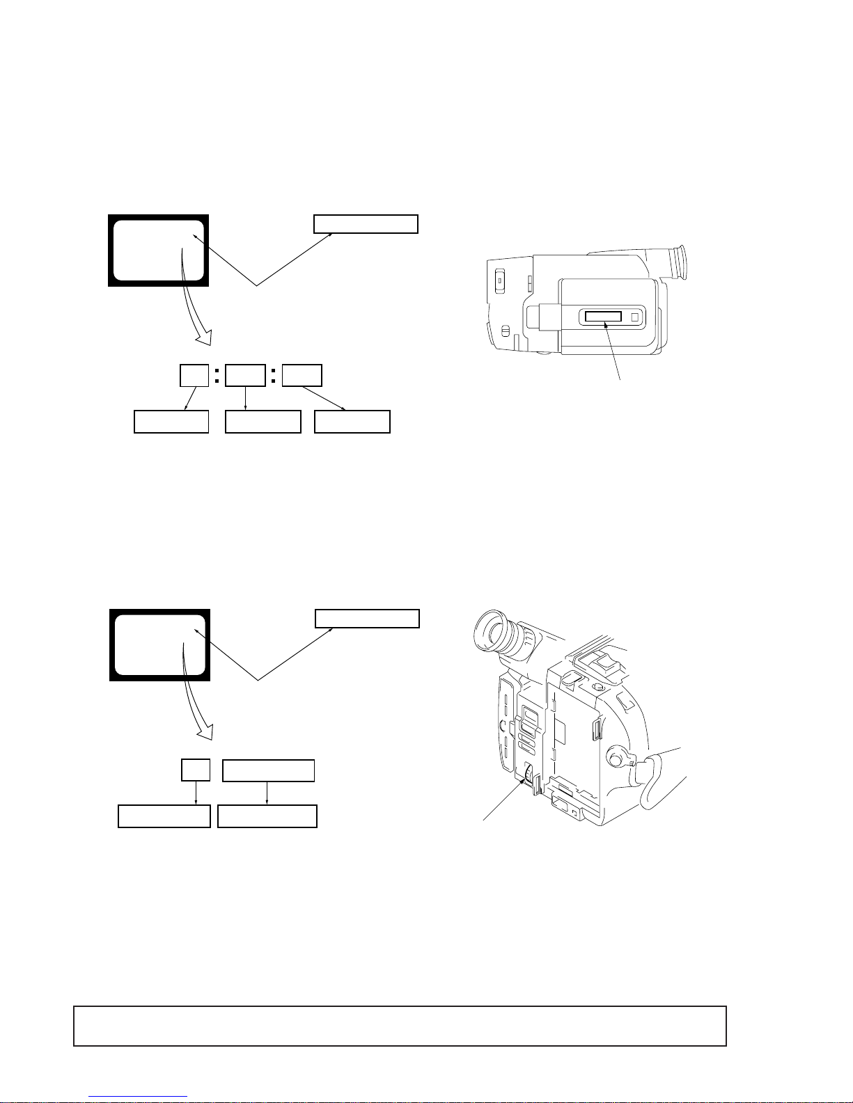
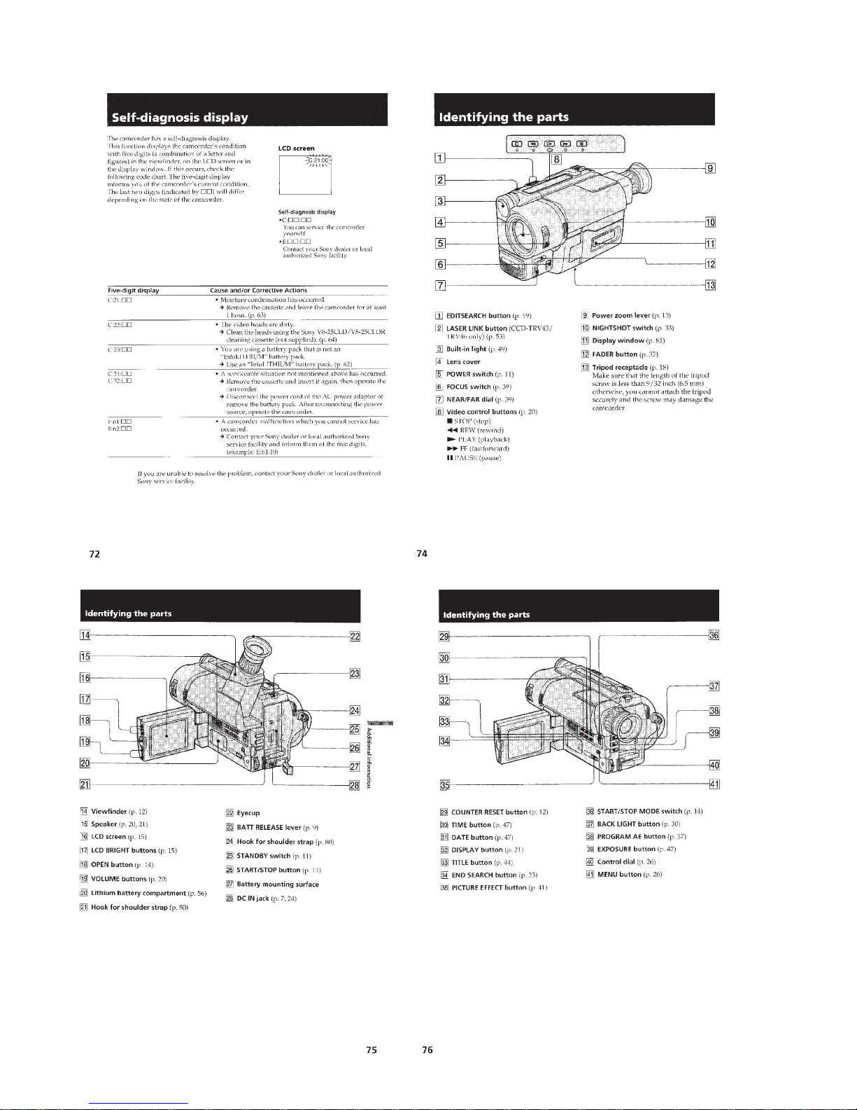
1. Self-diagnosis Function
When problems occur while the unit is operating, the self-diagnosis function starts working, and displays on the viewfinder or Display window what to do. This function consists of two display; selfdiagnosis display and service mode display.
Details of the self-diagnosis functions are provided in the Instruction manual.
SELF-DIAGNOSIS FUNCTION
2. Self-diagnosis display
When problems occur while the unit is operating, the counter of the
viewfinder or Display window shows a 4-digit display consisting
of an alphabet and numbers, which blinks at 3.2 Hz. This 5-character display indicates the “repaired by:”, “block” in which the problem occurred, and “detailed code” of the problem.
3. Service Mode Display
The service mode display shows up to six self-diagnosis codes shown in the past.
3-1. Display Method
While pressing the “STOP” key, set the switch from OFF to “VTR or PLAYER”, and continue pressing the “STOP” key for 5 seconds
continuously. The service mode will be displayed, and the counter will show the backup No. and the 5-character self-diagnosis codes.
3-2. Switching of Backup No.
By rotating the control dial, past self-diagnosis codes will be shown in order. The backup No. in the [] indicates the order in which the
problem occurred. (If the number of problems which occurred is less than 6, only the number of problems which occurred will be shown.)
[1] : Occurred first time [4] : Occurred fourth time
[2] : Occurred second time [5] : Occurred fifth time
[3] : Occurred third time [6] : Occurred the last time
3-3. End of Display
Turning OFF the power supply will end the service mode display.
Viewfinder
Display window
Blinks at 3.2 Hz
Refer to page7
Self-diagnosis Code table
C : Corrected by customer
H : Corrected by dealer
E : Corrected by service engineer
Repairede by :
Block
Detailed Code
Indicates the appropriate step to be taken
E. g.
31 ... Reload the tape.
32 ... Turn on power again.
C
3 1 1 1
C : 3 1 : 1 1
C : 3 1 : 1 1
Viewfinder
Display window
Lights up
Order of previous errors
Backup No.
Self-diagnosis codes
[3]
C : 3 1 : 1 1
3 C : 3 1 : 1 1
[3] C : 3 1 : 1 1
Display window
Control dial

– 7 –
Remove the cassette, and insert it again after one hour.
Clean with the optional cleaning cassette.
Use the InfoLITHIUM battery.
Load the tape again, and perform operations from the beginning.
Load the tape again, and perform operations from the beginning.
Load the tape again, and perform operations from the beginning.
Load the tape again, and perform operations from the beginning.
Load the tape again, and perform operations from the beginning.
Load the tape again, and perform operations from the beginning.
Load the tape again, and perform operations from the beginning.
Load the tape again, and perform operations from the beginning.
Load the tape again, and perform operations from the beginning.
Load the tape again, and perform operations from the beginning.
Load the tape again, and perform operations from the beginning.
Load the tape again, and perform operations from the beginning.
Load the tape again, and perform operations from the beginning.
Remove the battery or power cable, connect, and perform operations
from the beginning.
Remove the battery or power cable, connect, and perform operations
from the beginning.
Remove the battery or power cable, connect, and perform operations
from the beginning.
Remove the battery or power cable, connect, and perform operations
from the beginning.
Remove the battery or power cable, connect, and perform operations
from the beginning.
Remove the battery or power cable, connect, and perform operations
from the beginning.
Remove the battery or power cable, connect, and perform operations
from the beginning.
Remove the battery or power cable, connect, and perform operations
from the beginning.
Remove the battery or power cable, connect, and perform operations
from the beginning.
Remove the battery or power cable, connect, and perform operations
from the beginning.
Remove the battery or power cable, connect, and perform operations
from the beginning.
Remove the battery or power cable, connect, and perform operations
from the beginning.
Remove the battery or power cable, connect, and perform operations
from the beginning.
Inspect the lens block focus reset sensor (Pin !ª of CN551 of VC-215
board) when focusing is performed when the focus dial is rotated in the
focus manual mode and the focus motor drive circuit (IC552 of VC-215
board) when the focusing is not performed.
Note : Use the remote commander RM-95 only for the model without
the focus dial.
Inspect the lens block zoom reset sensor (Pin @¡ of CN551 of VC-215
board) when zooming is performed when the zoom lens is operated and
the zoom motor drive circuit (IC552 of VC215 boar d) when zooming is
not performed.
Inspect yaw angular velocity sensor (SE451 of SE-80/81 board)
peripheral circuits.
Inspect pitch angular velocity sensor (SE452 of SE-80/81 board)
peripheral circuits.
4. Self-diagnosis Code Table
Condensation.
Video head is dirty.
Non-standard battery is used.
LOAD direction. Loading does not
complete within specified time
UNLOAD direction. Loading does not
complete within specified time
T reel side tape slacking when unloading.
S reel side tape slacking when unloading.
T reel fault
S reel fault
FG fault when starting capstan
FG fault during normal capstan operations
FG fault when starting drum
PG fault when starting drum
FG fault during normal drum operations
PG fault during normal drum operations
Phase fault during normal drum operations
LOAD direction loading motor time-out
UNLOAD direction loading motor time-
out
T reel side tape slacking when unloading.
S reel side tape slacking when unloading.
T reel fault
S reel fault
FG fault when starting capstan
FG fault during normal capstan operations
FG fault when starting drum
PG fault when starting drum
FG fault during normal drum operations
PG fault during normal drum operations
Phase fault during normal drum operations
Difficult to adjust focus
(Cannot initialize focus.)
Zoom operations fault
(Cannot initialize zoom lens.)
Handshake correction function does not
work well.(With pitch angular velocity
sensor output stopped)
Handshake correction function does not
work well.(With yaw angular v elocity
sensor output stopped)
Self-diagnosis Code
Repaired by:
Block
Function
Detailed
Code
Symptom/State Correction
C
C
C
C
C
C
C
C
C
C
C
C
C
C
C
C
C
C
C
C
C
C
C
C
C
C
C
C
C
E
E
E
E
21
22
23
31
31
31
31
31
31
31
31
31
31
31
31
31
32
32
32
32
32
32
32
32
32
32
32
32
32
61
61
62
62
00
00
00
10
11
20
21
22
23
30
31
40
41
42
43
44
10
11
20
21
22
23
30
31
40
41
42
43
44
00
10
00
01

– 8 –
SERVICE NOTE
1. Power Supply During Repairs ................................................ 5
2. To Take out a Cassette when not Eject (Force Eject).............. 5
Self-Diagnosis Function
1. Self-diagnosis function ............................................................ 6
2. Self-diagnosis Display............................................................. 6
3. Service Mode Display ............................................................. 6
3-1. Display Method................................................................ 6
3-2. Switching of Backup No.................................................. 6
3-3. End of Display ................................................................. 6
4. Self-diagnosis Code Table ....................................................... 7
1. GENERAL
This section is extacked from instruction manual of
CCD-TRV36/TRV43/TRV46.
Using this manual ......................................................................1-1
Checking supplied accessories ..................................................1-1
Installing and Charging the battery pack...................................1-1
Inserting a cassette.....................................................................1-2
Camera recording ...................................................................... 1-2
Hints for better Shooting ...........................................................1-4
Checking the recorded picture...................................................1-4
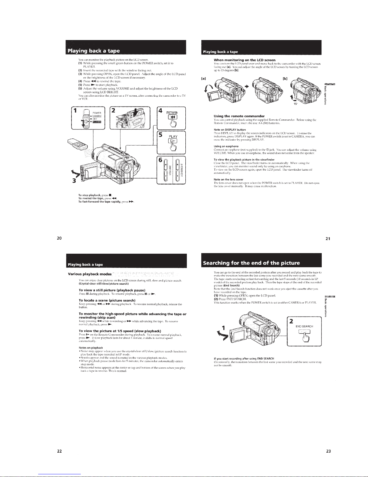
Playing back a tape .................................................................... 1-5
Searching for the end of the picture ..........................................1-5
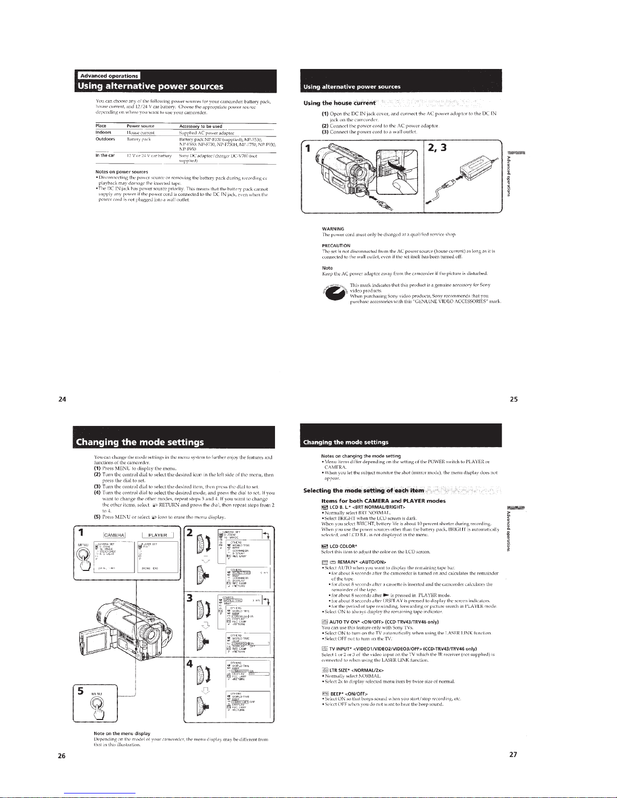
Using alternative power sources................................................1-6
Changing the mode settings ......................................................1-6
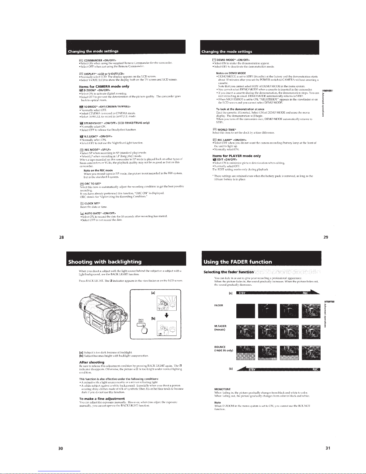
Shooting with backlighting .......................................................1-7
Using the F ADER function .......................................................1-7
Shooting in the dark (NightShot) ..............................................1-8
Using the wide mode function...................................................1-8
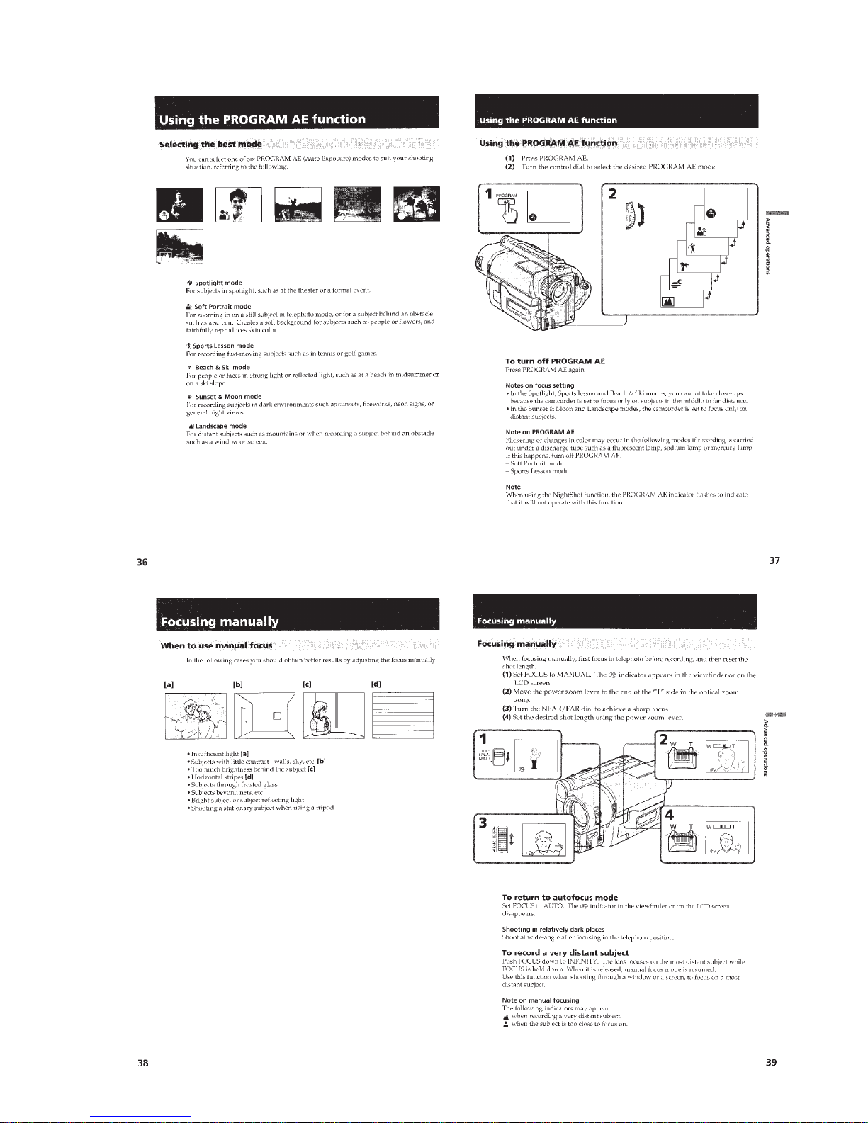
Using the PROGRAM AE function...........................................1-9
Focusing manually.....................................................................1-9
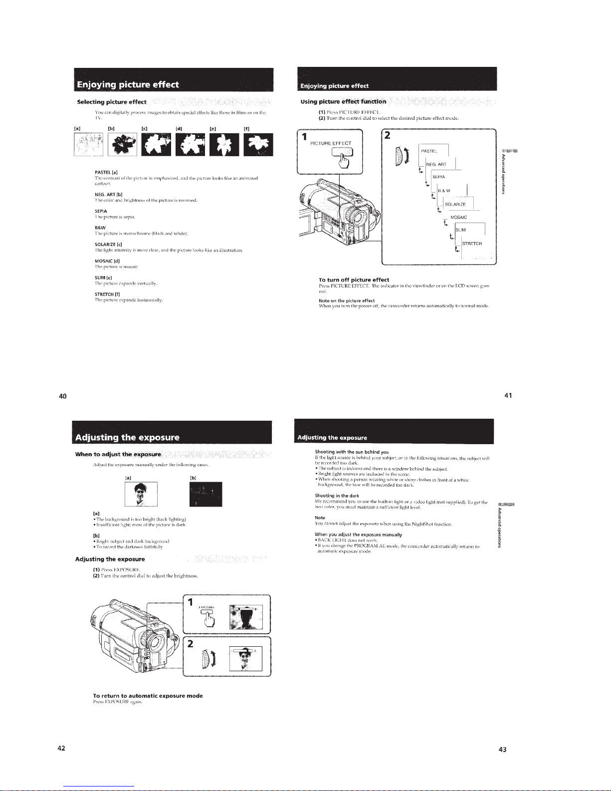
Enjoying picture effect ............................................................1-10
Adjusting the exposure ............................................................1-10
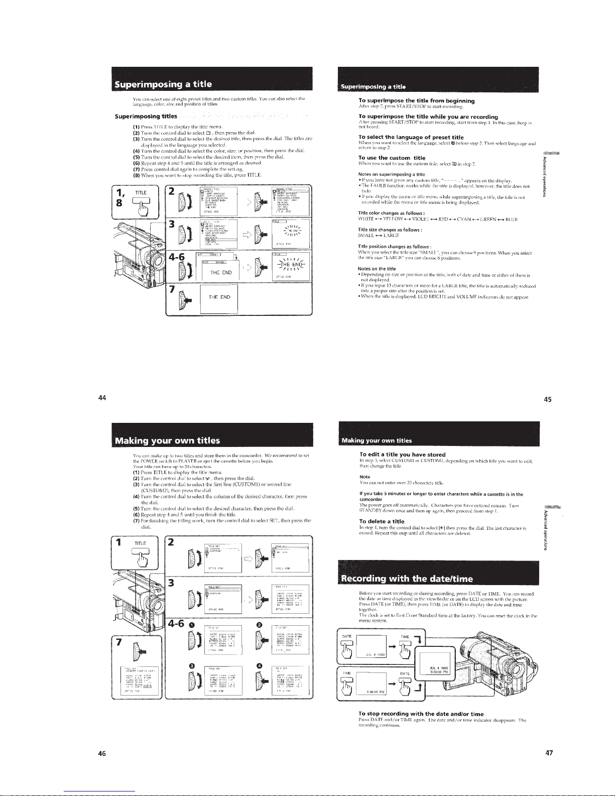
Superimposing a title ...............................................................1-11
Making your own titles............................................................1-11
Recording with the date/time...................................................1-11
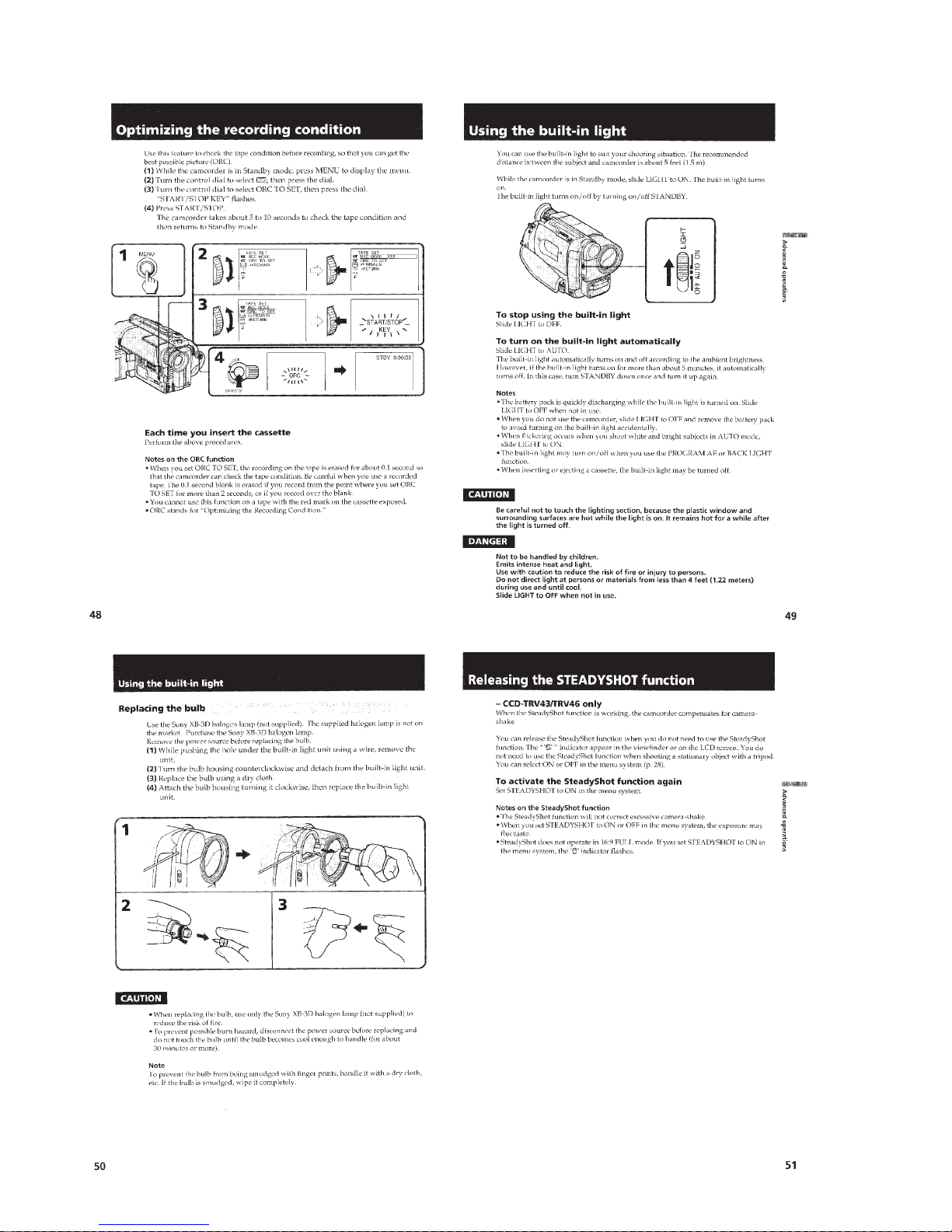
Optimizing the recording condition.........................................1-12
Using the built-in light.............................................................1-12
Releasing the STEADYSHOT function .................................. 1-12
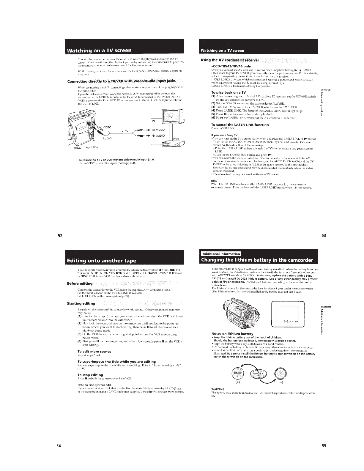
Watching on a TV screen.........................................................1-13
Editing onto another tape.........................................................1-13
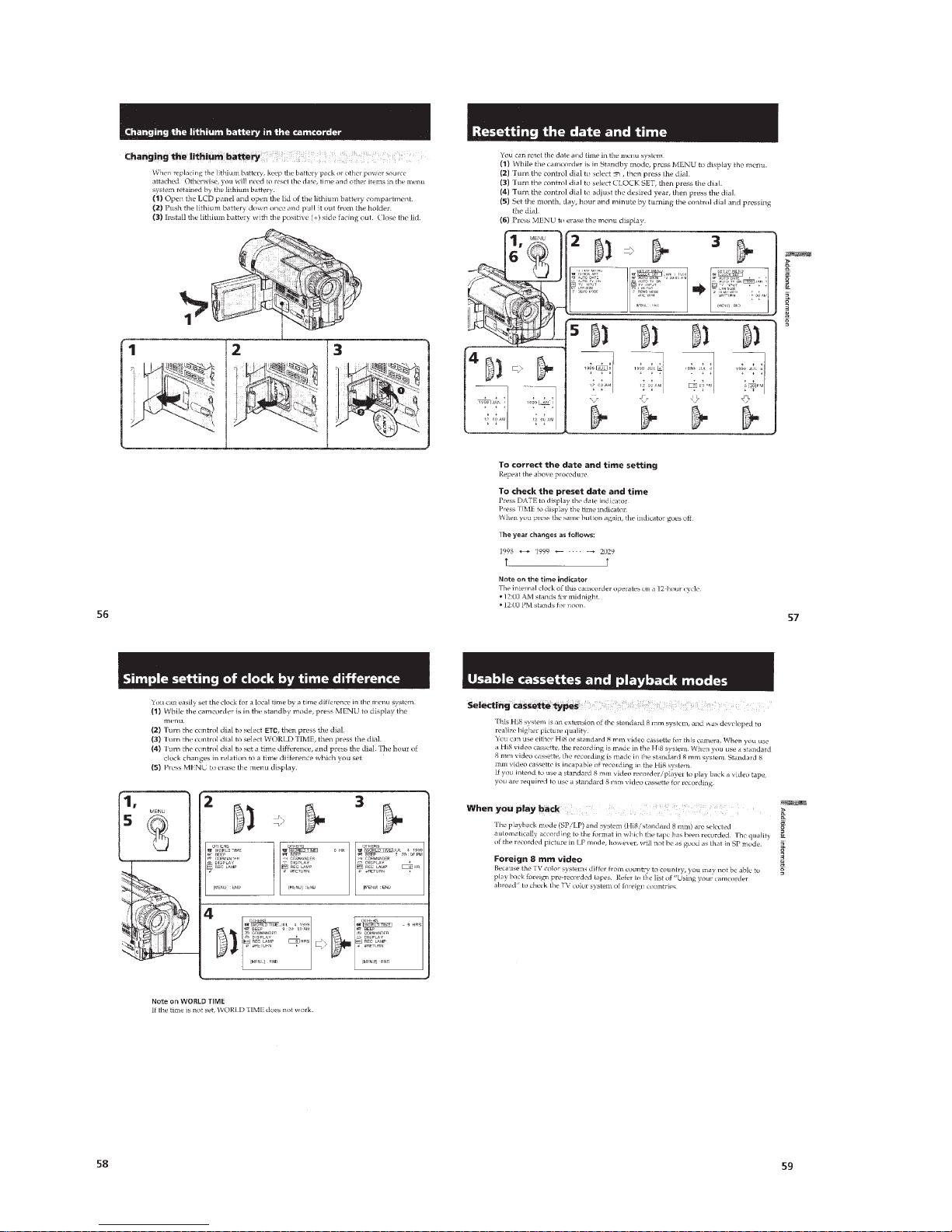
Changing the lithium battery in the camcoder ........................1-13
Resetting the date and time......................................................1-14
Simple setting of clock by time difference..............................1-14
Usable cassettes and playback modes ..................................... 1-14
Tips for using the battery pack ................................................1-15
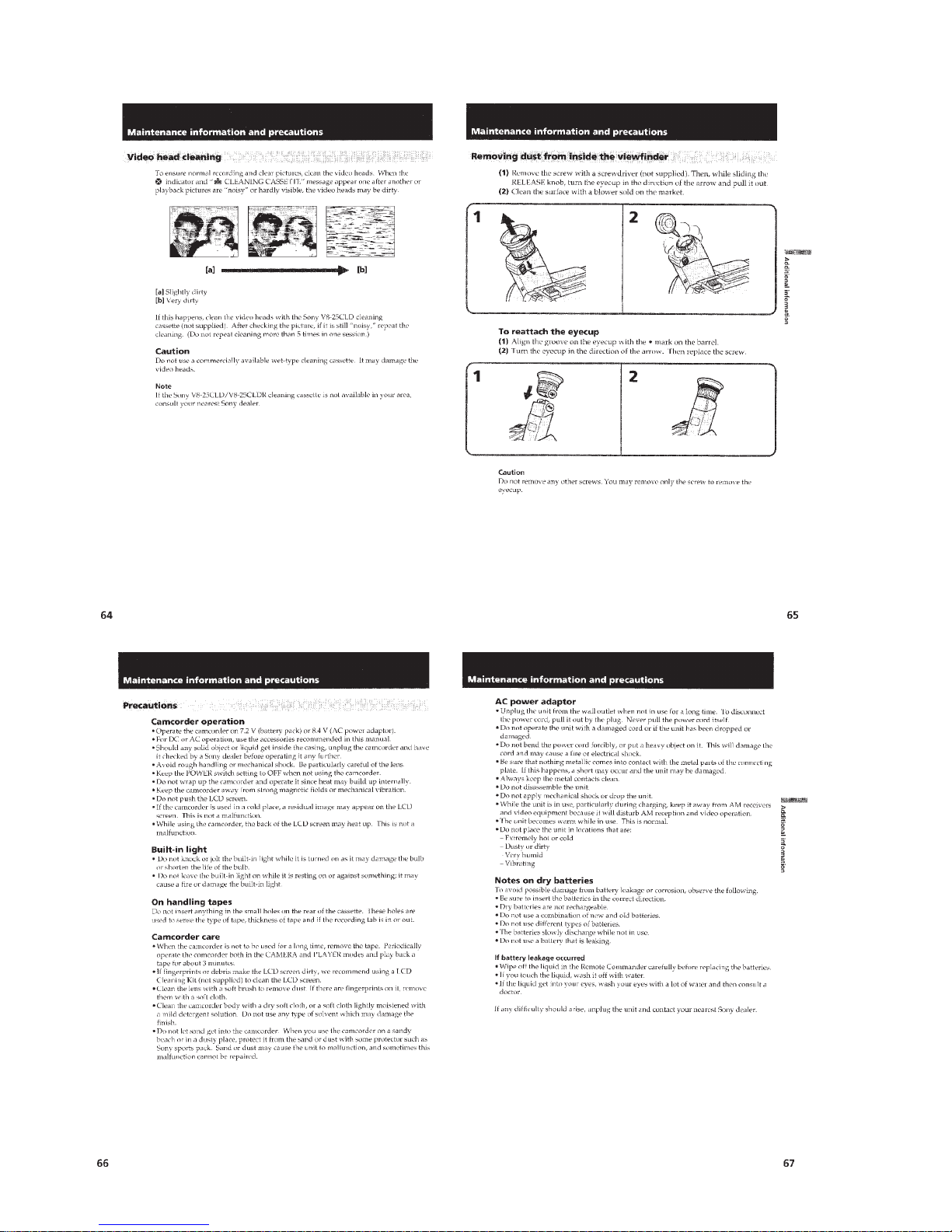
Maintenance information and precautions ..............................1-15
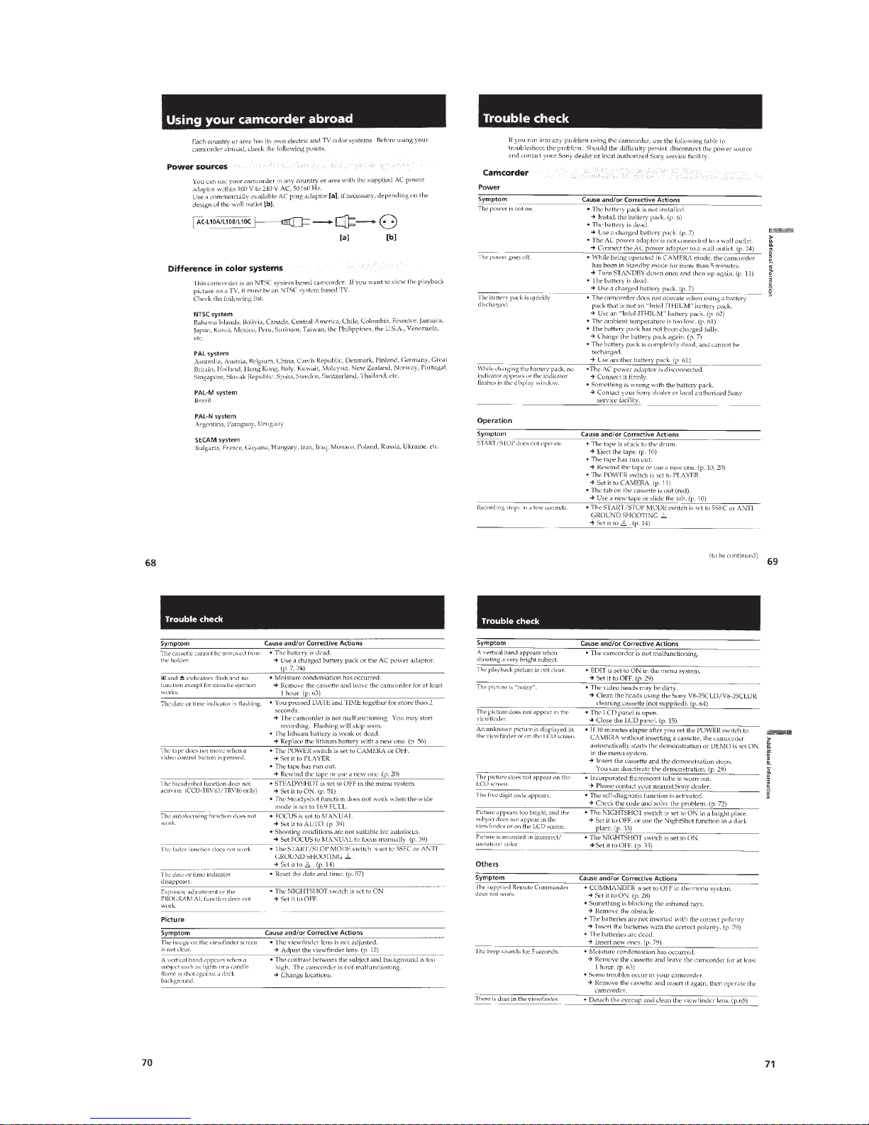
Using your camcorder abroad .................................................1-17
Truoble check ..........................................................................1-17
Self-diagnosis display..............................................................1-18
Identifying the parts.................................................................1-18
Warning Indicators ..................................................................1-20
TABLE OF CONTENTS
2. DISASSEMBLY
2-1. Removal of Front Panel Block and Video Light Block....2-1
2-2. Removal of LB-54, VF-119 and
VF-120 Boards (Color View Finder Models) ..................2-2
2-3. Removal of VF-99 Board and
CRT Assembly (B/W View Finder Models).....................2-2
2-4. Removal of Cabinet (R) Block.........................................2-3
2-5. Removal of Cassette Lid Assembly .................................2-3
2-6. Remov al of Battery P anel Block .......................................... 2-3
2-7. Removal of Cabinet (L) Block ......................................... 2-4
2-8. Removal of Control Switch Block (FK-8500) .................2-4
2-9. Removal of Zoom Lens Block and VL-20/21 Board.......2-4
2-10. Removal of DD-117 and PJ-90/91 Boards.......................2-4
2-11. Removal of VC-215 abd SE-80/81 Boards ......................2-5
2-12. Removal of View Finder Block........................................2-5
2-13. Removal of TR Cover, CF-60 Board and
Display Panel (TR series) ................................................2-6
2-14. Removal of IR Cover, CF-61 Board
and LCD Panel (TRV series)............................................2-6
2-15. Service Position ...............................................................2-7
2-16. Circuit Boards Location ...................................................2-8
2-17. Flexible Boards and Flat Cables Location ....................... 2-8
3. BLOCK DIAGRAMS
3-1. Overall Block Diagram ....................................................3-1
3-2. Camera/Video 1 Block Diagram ...................................... 3-5
3-3. VTR/Camera Control Block Diagram .............................3-9
3-4. Servo Block Diagram .....................................................3-12
3-5. Mode Control Block Diagram........................................3-15
3-6. Audio Block Diagram....................................................3-19
3-7. LCD Block Diagram (TRV model) ....................................3-23
3-8. Color EVF Block Diagram (Color EVF model)............3-26
3-9. B/W EVF Block Diagram (B/W EVF model) ............... 3-29
3-10. Power Block Diagram ....................................................3-33

– 9 –
4. PRINTED WIRING BOARDS AND SCHEMATIC
DIAGRAMS
4-1. Frame Schematic Diagram (1) ........................................... 4-1
• Frame Schematic Diagram (2) ........................................ 4-4
4-2. Printed Wiring Boards and Schematic Diagrams...............4-7
• CD-210/211 (CCD Imager) Board ..................................4-8
• VC-215 (Camera, Y/C Processor, IN/OUT,
REC/PB Head Amp, Servo/System Control, Servo,
Audio, IR Transmitter, Mode Control) Board ...............4-10
• VC-215 (Camera 1) Board ............................................4-17
• VC-215 (Camera 2) Board ............................................4-19
• VC-215 (Y/C Processor) Board ....................................4-23
• VC-215 (IN/OUT) Board ..............................................4-27
• VC-215 (REC/PB Head Amp) Board............................4-31
• VC-215 (Servo/System Control) Board ........................4-35
• VC-215 (Servo) Board ..................................................4-38
• VC-215 (Audio) Board .................................................. 4-41
• VL-20/21 (Video Light) Board (Video Light model)....4-45
• VC-215 (IR Transmitter) Board ....................................4-46
• VC-215 (Mode Control) Board .....................................4-49
• SE-80/81 (Steady Shot) Board ......................................4-52
• PJ-90/91 (AV OUT) Board ............................................4-55
• MA-345/346 (Mic, Laser Link) Board ..........................4-59
• CF-60 (Control (TR Series)) Board...............................4-65
• CF-61 (Control (TRV Series)) Board ............................ 4-72
• Control Switch Block (FK-8500/SS-8500) ................... 4-79
• PD-107 (RGB Decorder, LCD Drive,
Back Light, LCD (TRV Series)) Board .........................4-81
• PD-107 (RGB Decorder (TRV Series)) Board..............4-83
• PD-107 (LCD Drive (TRV Series)) Board....................4-86
• PD-107 (Back Light (TRV Series)) Board ....................4-89
• PD-107 (LCD (TRV Series)) Board .............................. 4-90
• VF-99 (B/W EVF (B/W EVF Model)) Board ...............4-92
• VF-119 (COLOR EVF (COLOR EVF Model)) Board ...... 4-95
• VF-120 (COLOR EVF (COLOR EVF Model)) Board .... 4-100
• LB-54 (Back Light (Color EVF model)) Board ..........4-102
• DD-117 (Power) Board ...............................................4-109
5. ADJUSTMENTS
5-1. CAMERA SECTION ADJUSTMENTS ..........................5-1
1-1. Preparations before Adjustment (Camera Section) ..........5-1
1-1-1. List of Service Tools .................................................5-1
1-1-2. Preparations...............................................................5-2
1-1-3. Precautions ................................................................5-5
1. Setting the Switch .....................................................5-5
2. Adjusting Procedure ..................................................5-5
3. Subject .......................................................................5-5
1-1-4. Adjusting Remote Commander .................................5-6
1. Using the adjusting remote commander....................5-6
2. Precautions upon using the adjusting
remote commander....................................................5-6
1-1-5. Data Processing .........................................................5-7
1-2. Initialization of D, E, F Page Data....................................5-8
1. Initialization the D, E, F Page Data...........................5-8
2. Modification of D, E, F Page Data...........................5-8
3. D Page Table .............................................................5-9
4. F Page Table............................................................5-10
5. E Page Table............................................................5-12
1-3. Camera System Adjustments ..........................................5-14
1. G-CAM flip Adjustment ......................................... 5-14
2. Hall Adjustment ......................................................5-15
3. Flange Back Adjustment .........................................5-16
3-1. Flange Back Adjustment (1) ...................................5-16
3-2. Flange Back Adjustment (2) ...................................5-16
4. Flange Back Check .................................................5-17
5. Picture Frame Setting ..............................................5-17
6. Color Reproduction Adjustment .............................5-18
7. IRIS IN/OUT Adjustment .......................................5-19
8. MAX GAIN Adjustment ......................................... 5-19
9. Auto White Balance Standard Data Input ...............5-20
10. Auto White Balance Adjustment.............................5-20
11. White Balance Check .............................................. 5-21
12. Angular Velocity Sensor Sensitivity Check ............5-22
1-4. Color Electronic Viewfinder System Adjustments
(CCD-TR416/TR416PK/TR516/TR516PK/TR716)......5-23
1. EVF Initial Data Input.............................................5-23
2. VCO Adjustment (VF-119 board)...........................5-24
3. Bright Adjustment (VF-119 board).........................5-24
4. Contrast Adjustment (VF-119 board) .....................5-25
5. Backlight Consumption Current Adjustment
(VF-120 board) .......................................................5-25
1-5. Monochrome Electronic Viewfinder
System Adjustments .......................................................5-26
1-5-1. Horizontal Slant Check ........................................... 5-26
1-5-2. Centering Adjustment .............................................5-26
1-5-3. Focus Adjustment ....................................................5-26
1-5-4. Aberration Adjustment ............................................5-27
1-5-5. Horizontal Amplitude Adjustment (VF-99 board) ..5-27
1-5-6. Vertical Amplitude Adjustment (VF-99 board).......5-28
1-5-7. Brightness Adjustments (VF-99 board) .................. 5-28
1-5-8. Horizontal Amplitude, V ertical Amplitude,
Focus Check ............................................................5-28
1-6. LCD System Adjustment (TRV Series) ..........................5-29
1. LCD initial data input ............................................. 5-29
2. VCO adjustment (PD-107 board) ........................... 5-30
3. D range adjustment (PD-107 board) .......................5-30
4. Bright adjustment (PD-107 board) .......................... 5-31
5. Contrast adjustment (PD-107 board) ......................5-31
6. V-COM adjustment (PD-107 board).......................5-32
7. Color adjustment (PD-107 board) ...........................5-32
8. V-COM adjustment (PD-107 board).......................5-33
9. White balance adjustment (PD-107 board) .............5-33

– 10 –
5-2. MECHANICAL SECTION ADJUSTMENT.................5-34
2-1. Operating without a Cassette..........................................5-34
2-2. Tape path Adjustment .....................................................5-34
1. Preparations for adjustments ...................................5-34
5-3. VIDEO SECTION ADJUSTMENTS.............................5-35
3-1. Preparations before Adjustment......................................5-35
3-1-1. Equipments to be Used ...........................................5-35
3-1-2. Precautions on Adjusting ........................................5-36
3-1-3. Adjusting Connectors ..............................................5-36
3-1-4. Connecting the Equipments ....................................5-37
3-1-5. Alignment Tape .......................................................5-37
3-1-6. Output Level and Impedance ..................................5-39
3-1-7. Recording Mode (Standard 8/Hi8) switching
(Hi8 model) .............................................................5-39
3-1-8. Service Mode ..........................................................5-39
1. Test mode setting.....................................................5-39
2. Emergency memory address ...................................5-40
2-1. EMG CODE (Emergency Code).............................5-40
2-2. MSW Codes ............................................................5-41
3. Bit value discrimination ..........................................5-42
4. Switch check (1) ......................................................5-42
5. Switch check (2) ......................................................5-43
6. Headphone jack check ............................................ 5-43
7. Input/output selection check ...................................5-43
8. LED, LCD (display window) check........................5-44
9. Record of use check ................................................5-44
3-2. System Control System Adjustment ...............................5-45
1. Initialization of D, E, F Page Data ..........................5-45
2. Battery End Adjustment (VC-215 board) ...............5-45
3-3. Servo System Adjustments .............................................5-46
1. CAP FG Offset Adjustment (VC-215 board)..........5-46
2. Switching Position Adjustment (VC-215 board) ....5-46
3-4. Video System Adjustments ..............................................5-47
1. 28 MHz Origin Oscillation Adjustment
(VC-215 board) .......................................................5-47
2. AFC f0 Adjustment (VC-215 board) ...................... 5-48
3. Filter f0 Adjustment (VC-215 board)...................... 5-48
4. Y OUT Level Adjustment (VC-215 board).............5-49
5. C OUT Level Adjustment (VC-215 board).............5-49
6. RP Filter f0 Adjustment (VC-215 board)................5-50
7. Hi8 REC Y Current Adjustment (VC-215 board)
(CCD-TR516/TR516PK/TR716 CCD-TRV36/
TRV36PK/TRV43/TRV46/TRV46PK) ...................5-51
8. Standerd8 REC Y Current Adjustment
(VC-215 board) (CCD-TR315/TR416/TR416PK
CCD-TRV16/TRV16PK) ........................................5-52
9. Hi8 REC L Level Adjustment (VC-215 board)
(CCD-TR516/TR516PK/TR716 CCD-TRV36/
TRV36PK/TRV43/TRV46/TRV46PK) ...................5-53
10. Standerd8 REC L Level Adjustment
(VC-215 board) (CCD-TR315/TR416/TR416PK
CCD-TRV16/TRV16PK) ........................................5-54
11. REC C Current Adjustment (VC-215 board)..........5-55
3-5. IR Transmitter Adjustments
(CCD-TR V43/TRV46/TRV46PK) ..........................5-56
1. IR Video Carrier Frequency Adjustment
(VC-215 board) .......................................................5-56
2. IR Video Deviation Adjustment (VC-215 board)....5-56
3. IR Audio Deviation Adjustment (VC-215 board) ...5-57
3-6. Monaural Audio System Adjustment ...............................5-58
1. 1.5 MHz Deviation Adjustment (VC-215 board)....5-59
2. BPF Adjustment (VC-215 board) ...........................5-59
3-7. Arrangement Diagram for Adjustment Parts ...................5-60
6. REPAIR PARTS LIST
6-1. Exploded Views .................................................................6-1
6-1-1. Remote Commander and Cassette Lid Assembly....6-1
6-1-2. Cabinet (L) and Battery Panel Assembly.................6-2
6-1-3. Front Panel Block Assembly....................................6-3
6-1-4. Cabinet (R) Block Assembly (TR series) ................6-4
6-1-5. Cabinet (R) Block Assembly (TRV series)..............6-5
6-1-6. Main Boards Block Assembly .................................6-6
6-1-7. Clolor EVF Block Assembly
(CCD-TR416/TR416PK/TR516/TR516PK/TR716) ..... 6-7
6-1-8. B/W EVF Block Assembly
(CCD-TR315 and TRV series).................................6-8
6-1-9. LCD Block Assembly (TRV series) .........................6-9
6-1-10. Zoom Lens Block Assembly..................................6-10
6-1-11. Cassette Compartment Assembly ..........................6-11
6-1-12. LS Chassis Assembly.............................................6-12
6-1-13. Mechanism Chassis Assembly...............................6-13
6-2. Electrical Parts List..........................................................6-14
1-1
SECTION 1
GENERAL
CCD-TR315/TR416/TR416PK/TR516/TR516PK/TR716
CCD-TRV16/TRV16PK/TRV36/TRV36PK/TRV43/TRV46/TRV46PK
This section is extracted
from instruction manual of
CCD-TRV36/TRV43/TRV46.
1-2
1-3
1-4
1-5
1-6
1-7

1-8
1-9
1-10
1-11
1-12
1-13
1-14
1-15
1-16
1-17
1-18
1-19
1-20
E
 Loading...