

Page 1

C-455-100-11(1)
Color Video Camera
Operating Instructions
Software Version 1.0
Before operating the unit, please read this manual thoroughly
and retain it for future reference.
BRC-X1000/H800
© 2016 Sony Corporation
Page 2

Table of Contents
Overview
Using This Manual ................................................ 4
Precautions for Preventing Access to the
Camera by an Unintended Third Party .............. 5
Features .................................................................. 6
Location and Function of Parts ........................... 7
Camera ............................................................ 7
Remote commander (supplied) ..................... 10
System Configuration ......................................... 13
Operating the camera using the supplied
remote commander ....................................... 13
Operating the camera using the remote
controller (not supplied) ............................... 13
Connecting multiple cameras to the remote
controller (not supplied) ............................... 14
Installation and Connection
Installing the Camera ......................................... 15
Installing the camera on a desk ..................... 15
Installing the camera at a high spot .............. 16
Connecting the Camera ...................................... 23
Connecting an AC power supply .................. 23
Connecting the camera to a PoE+ (Power over
Ethernet Plus) power supply device .............. 24
Connecting a single camera to a switcher,
recorder and monitor .................................... 25
Connecting a single camera to a single
remote controller (not supplied) ................... 26
Connecting a single camera to a single
remote controller (not supplied) ................... 26
Connecting multiple cameras to a single
remote controller (not supplied) ................... 27
Connecting a commercially available video
switcher ......................................................... 28
Externally synchronizing a single camera .... 29
Adjusting and Configuring through
On-Screen Menus
About On-Screen Menus .....................................30
Main menu ....................................................30
Setting menu .................................................30
How to Use Menus ...............................................31
Using the supplied remote commander .........31
EXPOSURE Menu ..............................................32
COLOR Menu .....................................................34
DETAIL Menu .....................................................35
KNEE Menu .........................................................36
GAMMA/VISIBILITY ENHANCER Menu ....36
GAMMA .......................................................36
VISIBILITY ENHANCER ...........................37
FOCUS Menu ......................................................37
PICTURE/OPTICAL FILTER Menu ...............38
PAN TILT/ZOOM Menu ....................................39
VIDEO OUT Menu .............................................39
SYSTEM Menu ....................................................40
NETWORK Menu ...............................................41
Operations Using the Supplied
Remote Commander
Before Starting Operations .................................42
Turning on the Power ..........................................42
Pan/Tilt and Zoom Operations ...........................42
Panning and Tilting .......................................42
Zooming ........................................................43
Operating multiple cameras with the remote
commander ....................................................44
Adjusting the Camera .........................................44
Focusing on a subject ....................................44
Shooting with back lighting ..........................44
Storing the Camera Settings in Memory
– Presetting Feature .............................................45
Upgrading the firmware
Before starting the operation ..............................46
Setting-up the PC ..........................................46
Accessing the camera using the Web
browser ..........................................................46
Operation .............................................................47
Firmware update tab ......................................47
Password tab ..................................................47
2
Page 3

Appendix
Message List ........................................................ 48
Troubleshooting ................................................... 49
Menu Configuration ........................................... 50
Preset Items .........................................................53
Specifications ....................................................... 55
Dimensions ................................................... 57
SYSTEM SELECT switch settings .............. 58
Pin array of the VISCA RS-422 terminal and
how to use it .................................................. 58
3
Page 4

Overview
NOTICE TO USERS
Safety Regulations (Supplied)
Describes the important points for safe use of the
camera.
Be sure to read it.
Operating Instructions (This document/
Web)
These operating instructions describe the names of the
various parts of camera and installation, connection, and
operation methods.
Using This Manual
The Operating Instructions is designed to be read on a
computer display.
The content you need to know in order to use the camera
is described here.
Read it before you operate the camera.
© 2016 Sony Corporation. All rights reserved. This
manual or the software described herein, in whole or
in part, may not be reproduced, translated or reduced
to any machine readable form without prior written
approval from Sony Corporation.
SONY CORPORATION PROVIDES NO
WARRANTY WITH REGARD TO THIS
MANUAL, THE SOFTWARE OR OTHER
INFORMATION CONTAINED HEREIN AND
HEREBY EXPRESSLY DISCLAIMS ANY
IMPLIED WARRANTIES OF
MERCHANTABILITY OR FITNESS FOR ANY
PARTICULAR PURPOSE WITH REGARD TO
THIS MANUAL, THE SOFTWARE OR SUCH
OTHER INFORMATION. IN NO EVENT SHALL
SONY CORPORATION BE LIABLE FOR ANY
INCIDENTAL, CONSEQUENTIAL OR SPECIAL
DAMAGES, WHETHER BASED ON TORT,
CONTRACT, OR OTHERWISE, ARISING OUT
OF OR IN CONNECTION WITH THIS MANUAL,
THE SOFTWARE OR OTHER INFORMATION
CONTAINED HEREIN OR THE USE THEREOF.
Jumping to a related page
When you read the instructions on a computer display
and click on the related part of the relevant page that is
being displayed, you jump to the related page. Relevant
pages can be searched easily.
Software display examples
The software displays described in this manual are
explanatory examples. Note that some displays may be
different from the ones that actually appear.
The illustrations of the camera and menu display in the
instructions show the BRC-X1000 as an example.
Printing the Operating Instructions
Depending on your system, certain displays or
illustrations in the Operating Instructions, when printed
out, may differ from those that appear on your screen.
Sony Corporation reserves the right to make any
modification to this manual or the information
contained herein at any time without notice.
The software described herein may also be governed
by the terms of a separate user license agreement.
• is trademark of Sony Corporation.
• “Exmor R” and are trademarks of
Sony Corporation.
• HDMI, HDMI High-Definition Multimedia
Interface, and HDMI logo is a trademark of HDMI
Licensing LLC and is registered trademark in
United States and/or other countries.
• Microsoft, Windows, and Internet Explorer are
registered trademarks of United States Microsoft
Corporation in the United States and/or other
countries.
• Java Script is a trademark of Sun Microsystems,
Inc.
• Adobe, Adobe Reader and Adobe Flash are
trademarks of Adobe Systems Incorporated.
Other system names, product names appearing in this
document are trademarks or registered trademarks of
their respective manufacturers. However,
in this document are not explicit.
®
, TM marks
4
Page 5

Precautions for Preventing Access to the Camera by an Unintended Third Party
The camera settings may be changed by an unintended
third party on the network, depending on the usage
environment.
The camera can be fraudulently accessed in a network
environment where a device is connected or connectable
to the network without the administrator's permission, or
where a PC or other network device connected to the
network can be used without any permission.
Connect to these environments at your own risk.
After configuring the camera, immediately change the
password you use for upgrading the firmware on the
camera with a Web browser on your PC. For how to
change password, refer to “Password tab” (page 47) in
“Updating the System”.
5
Page 6

Features
Pan/Tilt/Zoom CMOS video camera
equipped with a small built-in pan-tilt
head
• The camera unit is equipped with a 1.0-type Exmor R® CMOS
sensor and an optical 12× zoom lens with pan/tilt/zoom
features integrated into a small built-in pan-tilt head. This
versatile camera can be used for various applications.
• The pan-tilt head can pan to the right or left by ±170 degrees
and tilt upward to 90 degrees and downward to 30 degrees,
which allows the camera to remotely shoot wide areas.
• The camera pans and tilts smoothly, even at low movement
speed.
• The camera pans and tilts quietly, even at its maximum speed of
60 degrees per second.
High sensitivity and high resolution from
built-in 1.0-type CMOS image sensor
With the built-in highly photosensitive 1.0-type Exmor
®
R
CMOS sensor, high resolution shooting with less
noise can be achieved. Highly sensitive shooting unique
to the large sensor can be achieved. In addition, the
camera is equipped with a ZEISS Vario-Sonnar T* builtin lens.
Supports multi-format
3840 × 2160/29.97p (2SI)*
1920 × 1080/59.94p, 1920 × 1080/59.94i, 1280 × 720/
59.94p
3840 × 2160/25p (2SI)*
1920 × 1080/50p, 1920 × 1080/50i, 1280 × 720/50p
Switching possible with the SYSTEM SELECT switch
1
Compatible only with the BRC-X1000
*
1
1
Equipped with 3G-SDI and HDMI output
The camera can deliver 4K output for both Dual Link
3G-SDI × 2 (2SI) and HDMI.
Various installation environments are available in order
to establish a connection with HDMI, in addition to the
coaxial cable.
Equipped with PoE+ (Power Over
Ethernet Plus)
The camera is compatible with PoE+ (Power Over
Ethernet Plus), so a single LAN cable can be used for
power provision and control.
Adopting VISCA Camera Protocol
• The camera is equipped with a RS-422 communication
interface. The camera supports the industry-standard VISCA
camera protocol. Hence, a maximum of seven cameras can be
connected and remotely operated with high communication
speed (38,400 bps).
• Remote controller (not supplied) allows easy camera
operations.
Compatible with VISCA over IP protocol
An IP connection can be established between the camera
and the remote controller.
Equipped with External Video Sync Function
The camera is equipped with an external video sync
function to synchronize the camera images on multiple
cameras.
Equipped with Tally Lamp Function
The camera is equipped with a Tally lamp that quickly
distinguishes when the camera is in use.
The front Tally lamp is a large Tally lamp used for
improving visibility. The camera is also equipped with a
Tally lamp behind the camera block, in order to improve
visibility from the rear side.
6
Page 7
Location and Function
67
5
of Parts
Camera
Front (BRC-X1000)
1
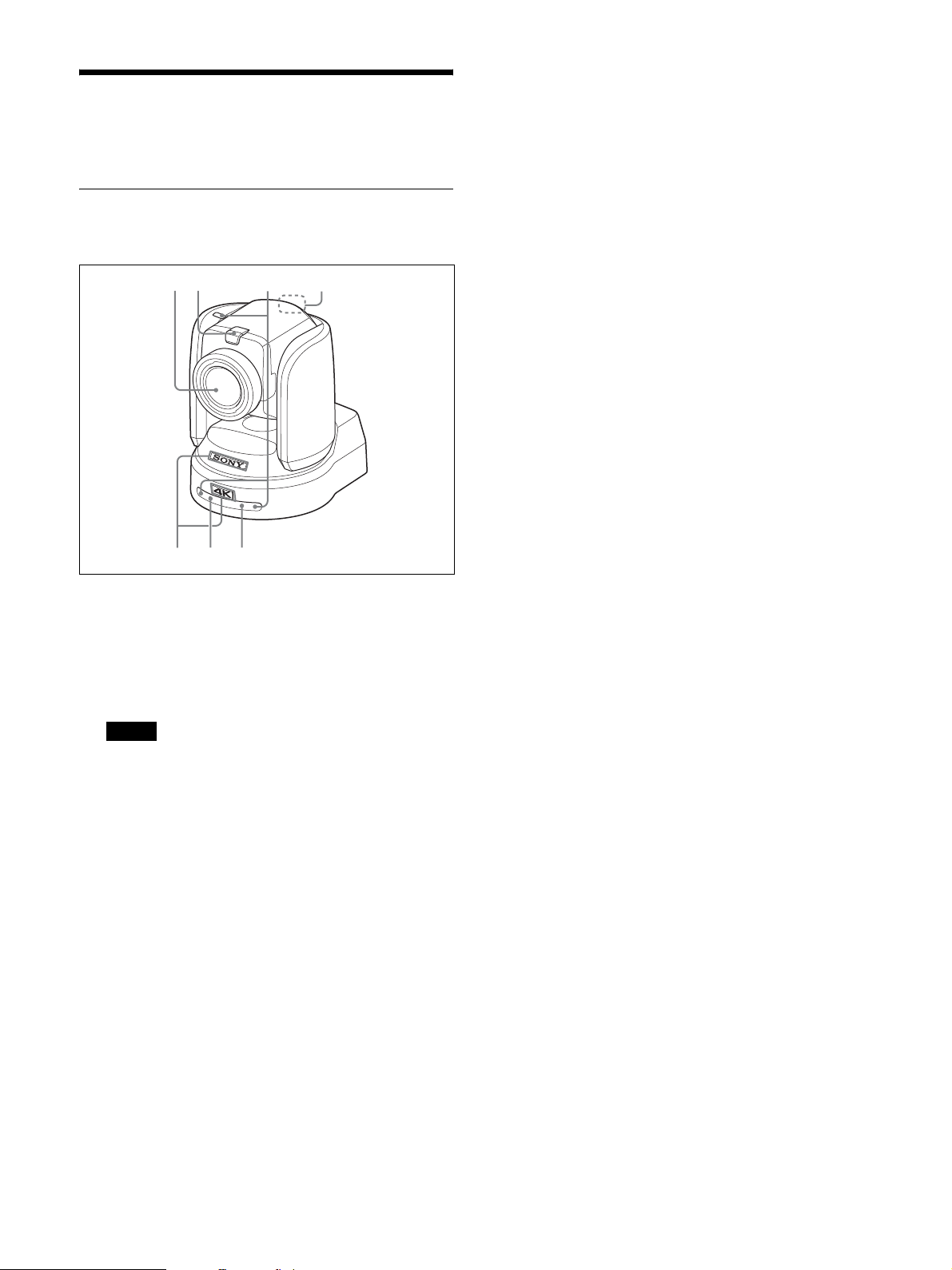
A Lens
This is a 12× magnification optical zoom lens.
When CLEAR IMAGE ZOOM in the PAN TILT
ZOOM menu is turned on, the camera can zoom up
to 18× for 4K and 24× for HD.
Note
Do not touch the part around the lens or the ring
outside the lens when energized. It may cause a
malfunction.
B Tally lamp
Lights up in red when a VISCA Tally command is
received or the camera is selected by the remote
controller (not supplied) (depending on the setting
mode). Brightness can be selected from HIGH,
LOW, and OFF (the lights are turned off) in TALLY
MODE in the SYSTEM menu.
C Remote commander sensors
These are sensors for the supplied remote
commander.
3
42
D Back Tally lamp
Lights up in red when a VISCA Tally command is
received or the camera is selected by the remote
controller (not supplied) (depending on the setting
mode). The back Tally lamp does not light up when
TALLY MODE in the SYSTEM menu (page 41) is
set to OFF.
If a fault inside the camera is detected, the lamp
flashes at approximately 0.7 second intervals
irrespective of the on/off status of the back Tally
lamp. When a fault is detected, its content will be
displayed in the menu (see page 48). If, however,
“CAMERA FAULT” is shown, the back Tally lamp
may not flash.
E SONY nameplate, 4K or HD nameplate
Pull them out to turn them over and attach upside
down if required.
4K: BRC-X1000
HD: BRC-H800
F POWER lamp
Flashes in green when the camera is connected to an
outlet using an AC adapter and power cord (not
supplied), or when power is being supplied by
connecting the camera and PoE+ Hub using a LAN
cable. The green lamp stops flashing and lights up
when start-up is complete.
The green lamp flashes when the camera receives an
operation command from the supplied remote
commander.
The orange lamp comes on when the POWER
button on the supplied remote commander is
pressed.
The yellow lamp flashes while upgrading the
firmware.
The yellow lamp flashes during a user version
upgrade.
The orange lamp flashes when there are defects in
the camera (for instance, when rotations of fan
motor slow down or stop etc.).
G Network lamp
Lamp flashes during initialization when it is
connected to a PoE+ Hub using a LAN cable and
power is being supplied from the PoE+ Hub. The
lamp lights up when it is connected to the network
once start-up is complete.
Lights up after start-up is complete if network is
connected, when power is supplied to the camera
from outlet using AC adapter and power cord. The
lamp is unlit when not connected to the network.
The lamp turns off while upgrading the firmware.
The lamp flashes when there are defects in the
camera (for example, when the fan motor stops).
7
Page 8
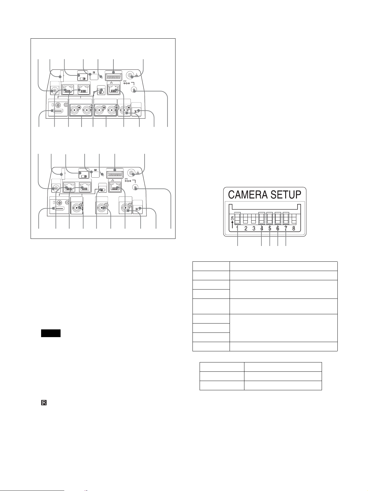
Back
q
qhq
w;wawswdw
q
q
1456 7
BRC-X1000
98 0 qa qs
SYSTEM
VISCA RS - 422 OUT
IN
SELECT
qg qh qj w; wa ws wd wfqlqk
BRC-H800
98 0 qa qs
SYSTEM
VISCA RS - 422 OUT
IN
SELECT
HDMI OUT
IR SELECT
123
MONITOR OUTHDMI OUT
SDI 1 SDI 2
IR SELECT
123
MONITOR
OUT
qd qf
CAMERA SETUP
ON
23456781
LAN
OSD
ON
OFF
LINE OUT
SDI 1
SDI 2
qd qf
CAMERA SETUP
ON
23456781
LAN
OSD
ON
OFF
LINE OUT
EXT SYNC IN
EXT SYNC IN
12V
12V
TERMI NATION
ON OFF
TERMI NATION
ON OFF
L Network reset switch
This switch is for initializing network settings such
as the IP address.
Press the switch for 5 seconds or longer with a pen
point, etc., to initialize the network settings.
The camera will reboot, and the network settings
will return to the factory default.
Factory settings for network
IP address: 192.168.0.100
Subnet mask: 255.255.255.0
Default gateway: 0.0.0.0
Name: CAM1
Password: Admin_1234
M CAMERA SETUP switches
SDI format/level settings
The baud rate settings and camera address settings
of RS-422 are set for VISCA communication.
CAMERA SETUP switch settings
g
j
l
k
H SYSTEM SELECT switch
Used for selecting the video format of the signal to
be output from the HDMI OUT, MONITOR OUT,
and LINE OUT terminals.
For details, see “SYSTEM SELECT switch
settings” (page 58).
I AC adapter cord clamper
Fix the cord of an AC adapter with the cord clamper
so that it does not come out.
Note
Do not use any AC adapter other than the specified
optional one. Otherwise, a fire or malfunction may
occur.
J IR SELECT switch
Select the camera number when you operate
multiple cameras with the same remote commander.
K Remote commander sensors
This is sensor for the supplied remote commander.
f
Switch No. Setting items
1 Setting up 3G-SDI level
2 System reserve
3
4 Baud Rate settings of RS-422 for VISCA
communication
5 VISCA Address settings for VISCA
6
communication
7
8 System reserve
1 SDI format/level settings
Switch state SDI format/level
ON Level-B
OFF Level-A
* Turn the power off or to standby, then turn the power
on to reflect the changes after setting
8
Page 9

4 Baud Rate settings of RS-422 for VISCA
communication
Switch state Baud Rate
ON 38,400 bps
OFF 9,600 bps
* Turn the power off and on to reflect the changes
after setting
567 Camera address settings
Sets camera address.
It is normally set to “Auto”. When “Auto” is
selected, an address is automatically assigned to the
camera.
To set the address manually, set a value between “1”
to “7” for this switch as indicated below.
Switch No.
56 7
OFF OFF OFF Auto
ON OFF OFF 1
OFF ON OFF 2
ON ON OFF 3
OFF OFF ON 4
ON OFF ON 5
OFF ON ON 6
ON ON ON 7
Camera
address
* Turn the power off and on to reflect the changes
after setting
N
U (earth) terminal
O HDMI OUT terminal
Supplies the images as an HDMI video signal.
* The contents of the menu screen, such as text, can
be displayed in the output signal when the OSD
switch is turned ON.
Notes
• When either 0 or 8 is selected for SYSTEM
SELECT, 2K output from the HDMI output
terminal results in lower quality images.
• When 7 is selected for SYSTEM SELECT, VGA
output from the HDMI output terminal results in
lower quality images.
P VISCA RS-422 IN terminal
Connect with an remote controller (not supplied).
When you connect multiple cameras, connect it to
the VISCA RS-422 OUT terminal of the previous
camera in the daisy chain connection.
Q VISCA RS-422 OUT terminal
When you connect multiple cameras, connect it to
the VISCA RS-422 IN terminal of the next camera
in the daisy chain connection.
R MONITOR OUT
Outputs the image from the camera as a 4K or HD
signal.
4K output:
Connect the SDI 1 (3G-SDI) output to the SDI 1
input and the SDI 2 (3G-SDI) output to the SDI 2
input respectively.
HD output:
Connect to SDI 1 (3G-SDI) or SDI 2 (3G-SDI).
* The contents of the menu screen, such as text, can
be displayed in the output signal when the OSD
switch is turned ON.
* For the BRC-H800, only HD output is available.
S OSD (On Screen Display) switch
The contents of the menu screen, such as text, can be
superimposed onto the video signal output to
MONITOR OUT & HDMI OUT when the switch is
turned ON.
T LINE OUT
Outputs the image from the camera as a 4K or HD
signal. OSD (screen display) is not superimposed,
irrespective of the OSD switch setting.
Equivalent signals are delivered to both SDI 1 and
SDI 2.
4K output:
Connect the SDI 1 (3G-SDI) output to the SDI 1
input and the SDI 2 (3G-SDI) output to the SDI 2
input respectively.
HD output:
Connect to SDI 1 (3G-SDI) or SDI 2 (3G-SDI).
* For the BRC-H800, only HD output is available.
U LAN (network) terminal (RJ-45)
Network communication and PoE+* power supply
are provided using the network cable (category 5e or
higher, shielded twist pair).
For more information on the connection, refer to the
instruction manual of the power supply system.
(*PoE+: an abbreviation of Power over Ethernet
Plus, which complies with IEEE802.3at)
The indicator lights up or flashes when the camera
is connected to the network.
The indicator is off when the camera is not
connected to the network.
V EXT SYNC IN
Accepts external video sync signals.
9
Page 10
W TERMINATION switch
Remote commander (supplied)
X 12 V
! (DC power input) terminal
Connect the AC adapter (not supplied).
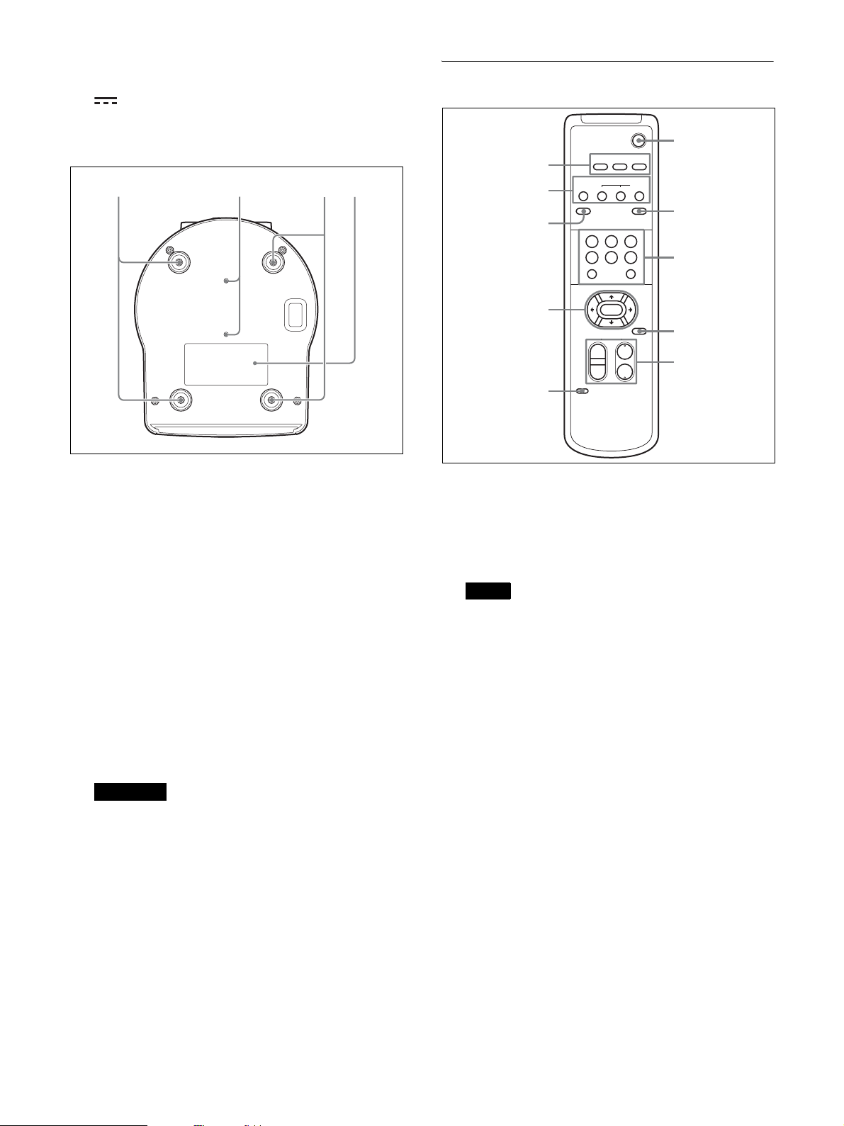
Bottom
whwg wg wj
wg Ceiling bracket mounting screw holes
When you install the camera to the ceiling, on a
shelf, or in another high spot, secure the supplied
ceiling bracket to these holes using four of the
supplied screws.
The four feet are attached to the holes at the factory.
POWER
6
CAMERA SELECT
23
1
2
3
4
5
1
AUTO
FAR
DATA SCREEN
STD REV
123
456
PRESET
SLOW FAST
T
W
L/R
DIRECTION SET
FOCUS
POSITION
PAN -T I LT
HOME
ZOOM
NEAR
RESET
T
W
MANUAL
BACK LIGHT
PAN -T I LT
RESET
7
8
9
q;
A CAMERA SELECT buttons
Press the button corresponding to the camera you
want to operate with the remote commander. The
camera number can be set using the IR SELECT
switch on the rear of the camera.
For installation, see “Installing the camera at a high
spot” (page 16).
wh Tripod screw holes (1/4-20UNC)
Used to fix the camera to the camera tripod or
something similar.
wj Rating label
This label shows the name of device and its electric
rating.
Important
The product name and electric rating are located at
the bottom of the unit.
Note
If two or more cameras are adjacent and have the
same camera number, they are operated
simultaneously with the supplied remote
commander. When you install the cameras close to
each other, set different camera numbers.
For setting of camera No., see “Operating multiple
cameras with the remote commander” (page 44).
B FOCUS buttons
Used for focus adjustment.
Press the AUTO button to adjust the focus
automatically. To adjust the focus manually, press
the MANUAL button, and adjust it with the FAR
and NEAR buttons.
10
Page 11

Notes
Press the MANUAL button and adjust the focus
manually when shooting the following objects.
• White walls and other objects without contrast
• Objects behind glass
• Objects with horizontal stripes
• Objects on which bright lights are cast or reflected
• Nightscapes and other dark objects with blinking
lights
• Lit objects shot with darkened exposure
adjustment or exposure compensation settings
C DATA SCREEN button
Press this button to display the main menu PAGE.
Press it again to close the menu. If you press the
button when a lower-level menu is selected, the
display goes back to a higher-level menu.
Notes
• You cannot perform pan/tilt/zoom operations
while the menu is displayed.
• The menus are output through MONITOR OUT
and HDMI OUT.
When you want to display the menus, turn on the
OSD switch on the back of the camera.
Note
The BACK LIGHT button is enabled when MODE
in the EXPOSURE menu is FULL AUTO,
SHUTTER Pri, IRIS Pri, or GAIN Pri.
H POSITION buttons
Hold down the PRESET button and press button 1 to
6 to store the current camera direction, zoom, focus
adjustment and backlight compensation in the
memory of the pressed number button.
To erase the memory contents, hold down the
RESET button and press button 1 to 6.
Notes
• These buttons do not function when the menu is
displayed.
• Some memory contents may not be erased even if
you use the RESET button.
For details on items that can be stored by the
PRESET button and erased by the RESET button,
see “Preset Items” (page 53).
I PAN-TILT RESET button
Press this button to reset the pan/tilt position.
D PAN-TILT button
Press the arrow buttons to pan or tilt the camera.
Press the HOME button to face the camera back to
the front.
When the menu is displayed, use
menu items and
B or b to change the set values.
V or v to select the
Display the menu of selected items with the HOME
button.
The selected setting menu is displayed by pressing
the HOME button when the main menu is displayed.
E L/R DIRECTION SET button
Hold down this button and press the REV button to
change the direction of the camera movement to be
opposite the direction of the arrows on the
buttons. To reset the direction of the camera
movement, press the STD button while holding
down this button.
F POWER button
Press this button to turn on power or to put the
camera in the standby mode.
J ZOOM buttons
Use the SLOW button to zoom slowly, and the
FAST button to zoom quickly.
Press the T (telephoto) side of the button to zoom in,
and the W (wide angle) side to zoom out.
B and b
G BACK LIGHT button
Press this button to enable backlight compensation.
Press it again to disable backlight compensation.
11
Page 12
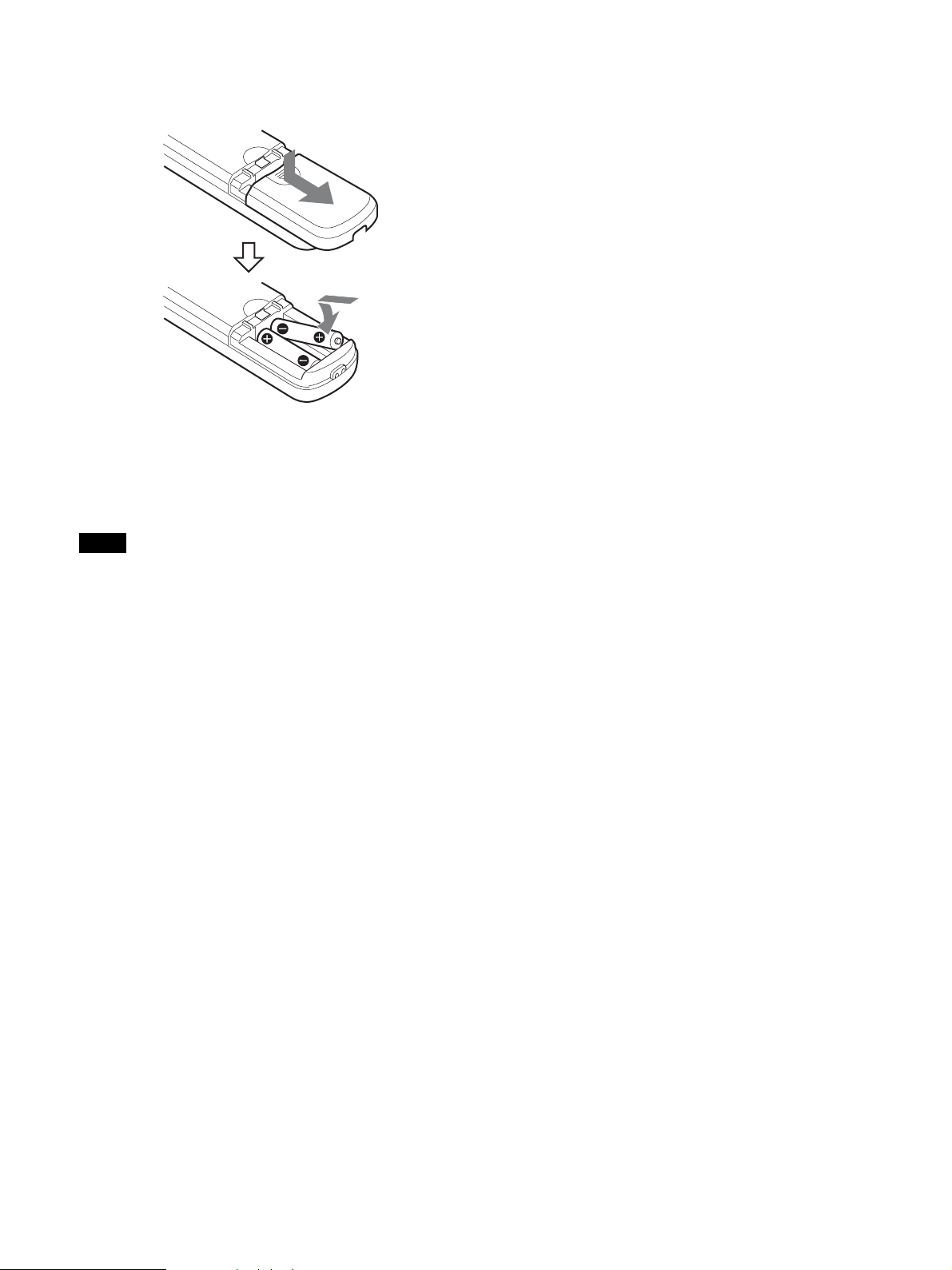
Installing Batteries in the remote
commander
Two R6 (size AA) batteries
(not supplied)
Installing batteries
Two R6 (size AA) batteries are required for the remote
commander. To avoid the risk of explosion, use R6 (size
AA) manganese or alkaline batteries.
Note
Danger of explosion if the batteries are incorrectly
replaced. Replace only with the same or equivalent type
recommended by the manufacturer. When you dispose
of the batteries, you must obey the laws of your area or
country.
R6 (size AA) batteries are not supplied.
12
Page 13
System Configuration
This camera can be arranged into various system configurations with other products (not supplied). This section
describes typical system examples, with the required components and the main usage of each system.
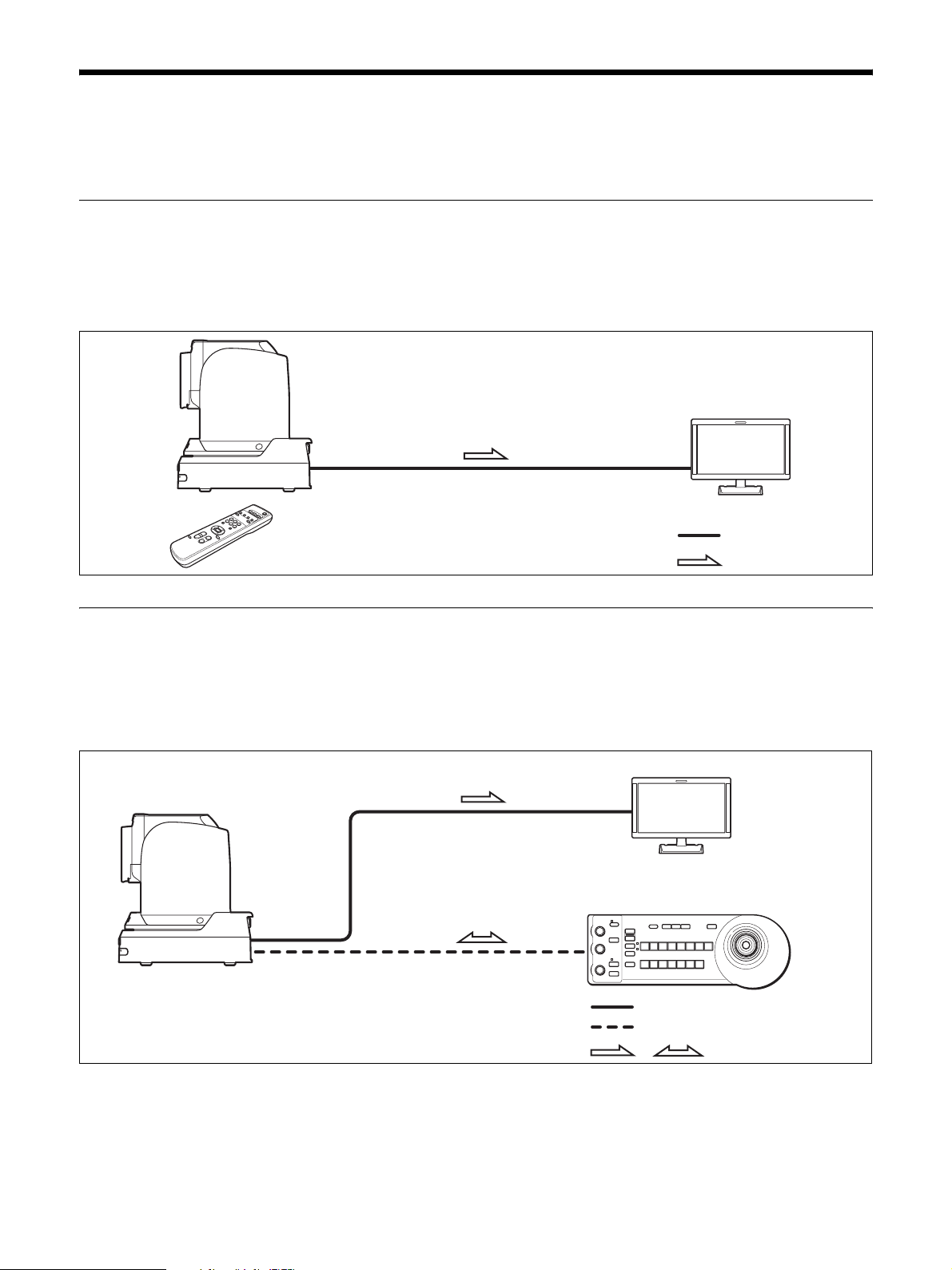
Operating the camera using the supplied remote commander
What you can do with this system
Operate the camera readily from a short distance.
System Configuration
Video monitor
Video signal
Remote commander (supplied)
Signal flow
Operating the camera using the remote controller (not supplied)
What you can do with this system
Perform pan/tilt and zoom operations using the joystick of the remote controller.
System Configuration
Video monitor
Remote controller
Video signal
Remote Control (VISCA) signal
,
Signal flow
13
Page 14
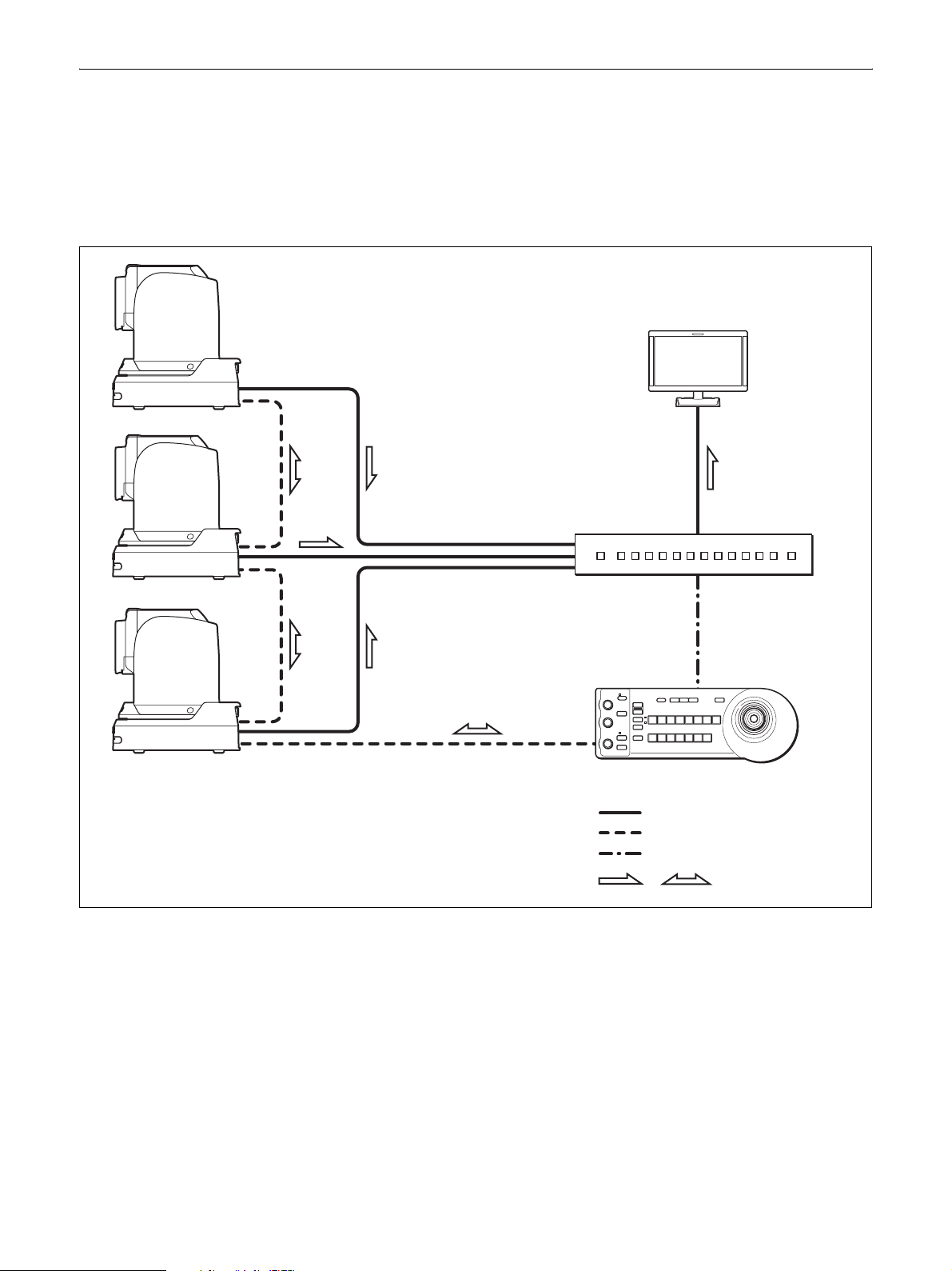
Connecting multiple cameras to the remote controller (not supplied)
What you can do with this system
• Operate up to seven cameras remotely using a single remote controller.
• Perform pan/tilt and zoom operations using the joystick.
System Configuration
Video monitor
Video switcher
14
Remote controller
Video signal
Remote Control (VISCA) signal
Tally/contact signal
,
Signal flow
Page 15
Installation and Connection
Installing the Camera
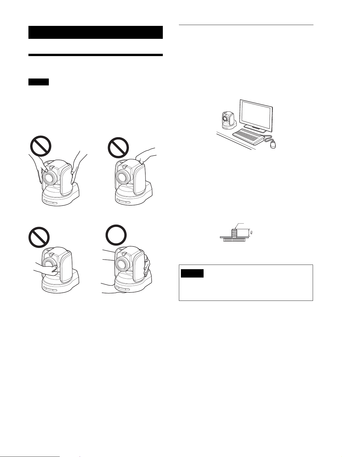
Notes
• Be sure to provide safety measures against falling
when you mount the camera.
• Do not grasp the camera head when carrying the
camera.
• Do not turn the camera head by hand. Doing so may
result in a camera malfunction.
Installing the camera on a desk
Installing the camera on a desk
Place the camera on a flat surface.
If you have to place the camera on an inclined surface,
make sure that the inclination is less than ±15 degrees to
guarantee pan/tilt performance, and take measures to
prevent it from falling.
Attaching the camera to a tripod
Screw the tripod screw into a tripod screw hole on the
bottom of the camera.
The tripod should be placed on a level surface, and
tighten the screw firmly by hand.
The tripod screw should be compliant with the following
standards.
1
/4 -20UNC
4 = 4.5 - 7 mm
4 = 0.18 - 0.27 inches
Caution
Installation of the camera using the tripod screws and
screw holes should not be done for installation on a
ceiling, shelf, or other high spot.
15
Page 16
Installing the camera at a high spot
The camera can be mounted on a ceiling or on a shelf or
stand located at a high spot using the supplied ceiling
bracket.
The surface on which the camera will be mounted
should be level. If you have to mount the camera on a
tilted surface, make sure that the angle is less than 15
degrees to ensure the camera can pan/tilt properly.
Caution
• When you want the camera to be mounted at a high
spot, such as on a ceiling, have a professional
contractor do the job.
• When you mount the camera at a high spot, make
sure the attachment materials to which the camera
will be mounted and the fittings (except for
accessories) are capable of supporting a weight of
60 kg or greater and that the installation is done
properly. If the installation is not strong enough, the
camera may fall, resulting in a serious injury.
• As a fall prevention measure, be sure to attach the
supplied wire rope to the camera securely.
• When you mount the camera at a high spot, inspect
the installation once a year for any loosened parts.
Depending on the operation conditions, inspect
more frequently.
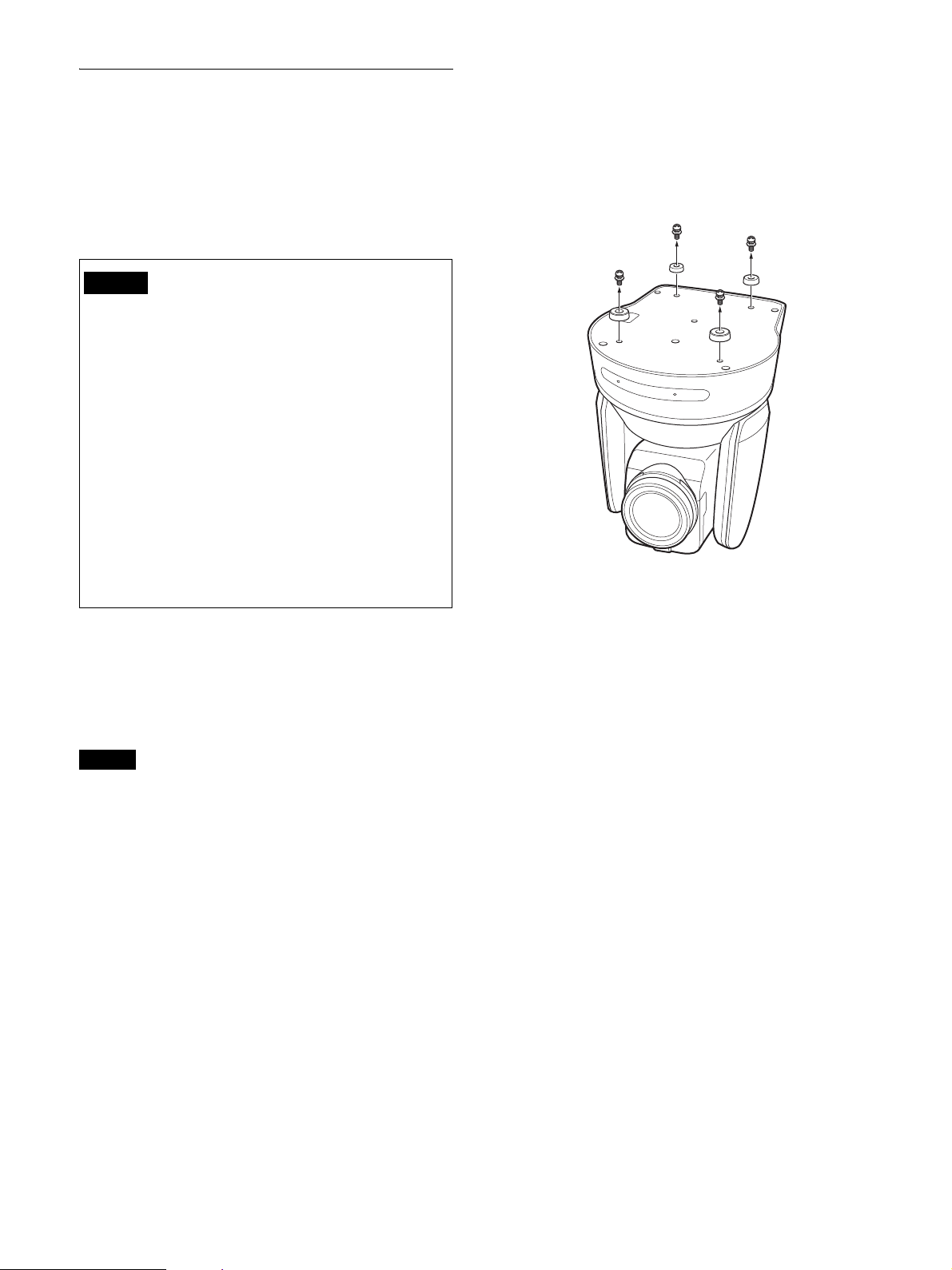
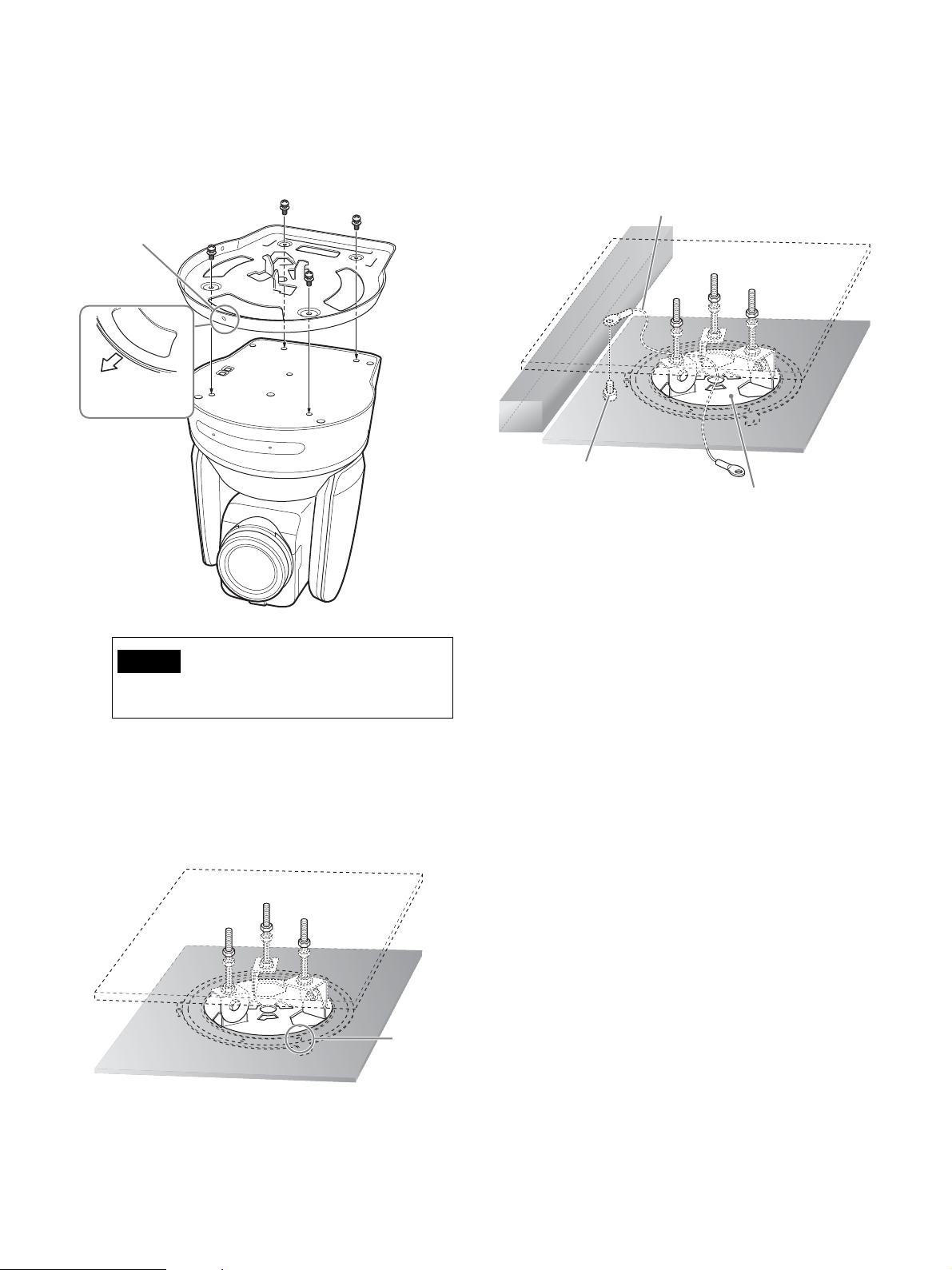
Installing the camera on the ceiling
(example)
1
Turn on IMG FLIP in the SYSTEM menu.
2
Loosen the four screws at the bottom of the camera
to remove the four feet.
Before installing the camera
Decide which way the camera will shoot, and drill holes
for the ceiling bracket (B) and the connecting cable in
the ceiling or the shelf. For the dimensions of the ceiling
bracket (B), refer to page 57.
Notes
• Connection cables cannot be routed through the
ceiling bracket (A). A hole to route wires through is
needed in the ceiling or the shelf at the back of the
camera.
• Do not mount anything other than the camera onto the
ceiling bracket.
• The ceiling bracket cannot be mounted on a junction
box.
16
Page 17
3
Attach the ceiling bracket (A) to the bottom of the
camera by using supplied four screws (3 M3 × 8).
Align the a mark of the bracket (A) with the front
of the camera as illustrated, with the screw holes of
the bracket aligned to the screw holes of the camera.
3 M3 × 8 (supplied)
Ceiling
bracket (A)
a mark
Front of the
camera
5
Attach the wire rope for fall prevention to the
ceiling.
Using an M5 (3/16 inches) socket cap screw (not
supplied), attach it to the attachment materials
different from the one to which the ceiling bracket
(B) is attached.
Wire rope (supplied)
Attachment
materials
Ceiling
M5 (3/16 inch) socket
cap bolt
Ceiling bracket (B)
Caution
Use the supplied screws. Otherwise, you may
break the internal parts of the camera.
4
Attach the ceiling bracket (B) to the attachment
materials (not supplied) to mount the camera on the
ceiling.
Be sure to attach it so that the f hole of the ceiling
bracket (B) is placed where the front of the camera
will face.
Attachment materials
Ceiling bracket (B)
Ceiling
f hole
17
Page 18
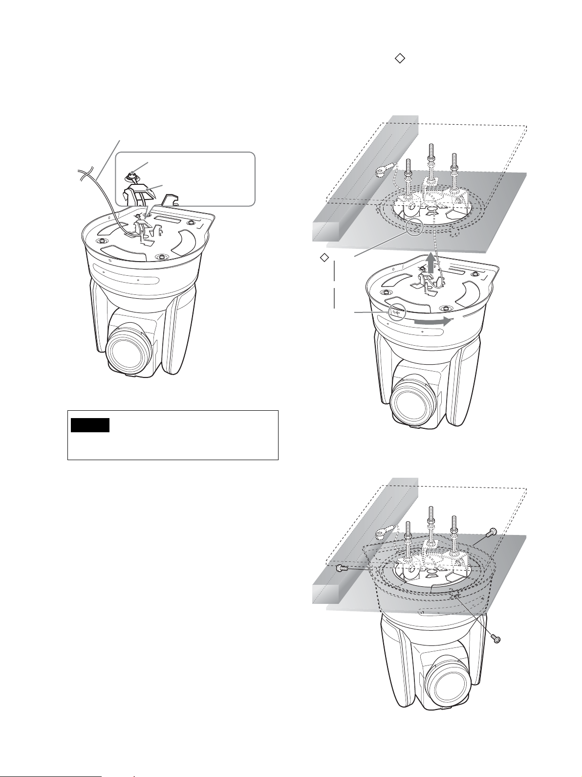
6
Attach the wire rope for fall prevention to the ceiling
bracket (A).
Put the wire rope through the fitting for wire rope of
the ceiling bracket (A) and securely attach it to the
bracket using the supplied stainless steel screw
(3 M4 × 8).
Wire rope (supplied)
3M4 × 8 (supplied)
Fitting for wire rope
7
Aligning the a hole in the front of the ceiling
bracket (A) to the hole of the ceiling bracket (B),
push in the camera unit, and turn the camera with the
ceiling bracket (A) clockwise to temporarily secure
the camera.
Ceiling
bracket (A)
Caution
Use the supplied screw. Otherwise, the wire rope
may not function properly.
Ceiling
mark
1
Align
a mark
2
8
Secure the ceiling brackets (A) and (B) using
supplied three screws (3 M3 × 8).
3M3 × 8
(supplied)
Ceiling
bracket (B)
Ceiling
bracket (A)
18
Ceiling
Page 19

9-1
Connect the cables to the terminals at the back of
the camera.
Ceiling
Notes
• Make sure no load is applied to connectors of the
cables.
• For measures that prevent the cord of the AC
adapter (not supplied) from being pulled out,
refer to “Connecting the Camera” (page 23).
• For measures that prevent the HDMI cable from
being pulled out, proceed to “9-2” after
connecting the HDMI cable. Then, connect all
the other cables.
9-2
To help prevent the HDMI cable from being pulled
out, remove the HDMI cable locking screw
(M2.6 × 6, black), and use it to attach the supplied
HDMI cable fixing plate to the back of the camera.
Secure the HDMI cable with a commercially
available tie-wrap.
HDMI cable locking screw (M2.6 × 6, black)
Tie-wrap (commercially
HDMI cable fixing plate (supplied)
Note
Do not leave the HDMI cable attached to the camera
if you do not use it.
10
Flip the SONY nameplate and 4K or HD nameplate
around as necessary.
available)
How to remove the camera
1
Remove the three screws which secured the camera
in Step 8 of “Installing the camera on the ceiling
(example)”.
2
Turn the camera unit counter-clockwise to remove
it.
19
Page 20

Installing the camera on a shelf located
at a high spot (example)
1
Loosen the four screws at the bottom of the camera
to remove the four feet.
Note
Use the supplied screws. Otherwise, you may break
the internal parts of the camera.
3
Attach the wire rope for fall prevention to the ceiling
bracket (A).
Put the wire rope through the fitting for wire rope of
the ceiling bracket (A) and securely attach it to the
bracket using the supplied stainless steel screw (3
M4 × 8).
Wire rope (supplied)
3M4 × 8 (supplied)
Fitting for wire rope
Ceiling
bracket (A)
2
Attach the ceiling bracket (A) to the bottom of the
camera by using supplied four screws (3 M3 × 8).
Align the a mark of the bracket (A) with the front
of the camera as illustrated, with the screw holes of
the bracket aligned with the screw holes of the
camera.
3M3 × 8 (supplied)
a mark
Front of the
camera
Caution
Use the supplied screw. Otherwise, the wire rope
may not function properly.
Ceiling
bracket (A)
20
Page 21

4
Mount the ceiling bracket (B) onto the shelf where
the camera will be mounted.
Use four screws (not supplied). Choose the right
type of screws for the material of the shelf.
Be sure attach it so that the f hole of the ceiling
bracket (B) is placed where the front of the camera
will face.
Wall
Screws (4)
Ceiling
f hole
bracket (B)
5
Attach the wire rope for fall prevention to the
attachment materials on the shelf side.
Using an M5 (3/16 inches) socket cap screw (not
supplied), attach it to the attachment materials
different from the one to which the shelf containing
the ceiling bracket (B) is attached.
Shelf
Hole for
connecting cable
Wire rope
(supplied)
M5 socket cap bolt
21
Page 22

6
Aligning the a hole in the front of the ceiling
bracket (A) to the
hole of the ceiling bracket (B),
push in the camera unit, and turn the camera with the
ceiling bracket (A) clockwise to temporarily secure
the camera.
Ceiling
bracket (A)
3M3 × 8 (supplied)
a mark
Ceiling
bracket (B)
7
Secure the ceiling brackets (A) and (B) using
supplied three screws (3 M3 × 8).
Align
mark
8
Connect the cables to the terminals at the back of the
camera.
22
Page 23

Notes
• Make sure no load is applied to the connectors of
the cables.
• For measures that prevent the cord of the AC
adapter (not supplied) or HDMI cable from being
pulled out, refer to “Connecting the Camera”
(page 23).
• For measures that prevent the HDMI cable from
being pulled out, follow the steps in “9-2” of
“Installing the camera to the ceiling (example)”
after connecting the HDMI cable. Then, connect
all the other cables.
How to remove the camera
1
Remove the three screws which secured the camera
in Step 7 of “Installing the camera on the shelf at a
high spot (example)”.
2
Turn the camera unit counterclockwise to remove it.
Connecting the Camera
Connecting an AC power supply
Connect the AC adapter (not supplied) to the AC power
supply using a power supply cord.
IR SELECT
CAMERA SETUP
123
ON
23456781
SYSTEM
IN
VISCA RS - 422 OUT
SELECT
MONITOR OUTHDMI OUT
SDI 1 SDI 2
12V
LAN
OSD
OFF
ON
LINE OUT
EXT SYNC IN
SDI 1
SDI 2
TERMI NATION
ON OFF
AC adapter
(not supplied)
To power supply
1
Connect the AC adapter (not supplied) and a power
supply cord.
23
Page 24

2
To prevent the cord of the AC adapter (not supplied)
from being pulled out, use the cord clamper to
secure it.
Unlock the cord clamper and put the cord through it.
Lock the cord clamper.
AC adapter cord clamper
Cord clamper lock
1 Unlock the cord clamper lock.
AC adapter cord
Connecting the camera to a PoE+ (Power over Ethernet Plus) power supply device
A PoE+ (IEEE802.3at compliant) power supply device
supplies power through a commercially available
network cable. For details, see the operating instructions
of the power supply device.
IR SELECT
CAMERA SETUP
123
ON
23456781
SYSTEM
IN
VISCA RS - 422 OUT
SELECT
MONITOR OUTHDMI OUT
SDI 1 SDI 2
12V
LAN
OSD
ON
OFF
LINE OUT
EXT SYNC IN
SDI 1
SDI 2
TERMI NATION
ON OFF
2 Put the AC adapter cord through the cord clamper and
lock the cord clamper.
Note
Do not use any cord other than the specified AC adapter
(not supplied). Otherwise, a fire or malfunction may
occur.
Network cable
(commercially
available)
Hub with PoE+
power supply
feature
Notes
• When you supply power from a PoE+ power source,
use a network cable of Category 5e or higher.
• When both the AC adapter and PoE+ power supply
are connected, power is supplied through the AC
adapter.
• When power is supplied from PoE+, both the POWER
lamp (green) and NETWORK lamp (green) flash until
the initial verification process is complete
(approximately one minute, depending on the power
supply device).
• When the network camera is powered by a PoE+
power supply, do not route the wiring outdoors.
When you use PoE+ for the power supply, connect the
ground wire.
24
Page 25

• If a non PoE+ compatible device is connected, both
the POWER lamp (green) and NETWORK lamp
(green) flash, and the camera won’t start.
• When you turn the power off, wait at least 10 seconds
before you turn it on again.
• Use an STP (shielded) network cable.
Connecting a single camera to a switcher, recorder and monitor
Devices equipped with an SDI input terminal
(4K output): BRC-X1000
IR SELECT
CAMERA SETUP
123
ON
23456781
SYSTEM
IN
VISCA RS - 422 OUT
SELECT
MONITOR OUTHDMI OUT
SDI 1 SDI 2
12V
LAN
OSD
OFF
ON
LINE OUT
EXT SYNC IN
SDI 1
SDI 2
SDI OUT
TERMI NATION
ON OFF
Devices equipped with an HDMI input terminal
IR SELECT
CAMERA SETUP
123
ON
23456781
SYSTEM
IN
VISCA RS - 422 OUT
SELECT
HDMI cable
(not supplied)
Video monitor
MONITOR OUTHDMI OUT
SDI 1 SDI 2
12V
LAN
OSD
OFF
ON
LINE OUT
EXT SYNC IN
SDI 1
SDI 2
TERMI NATION
ON OFF
To HDMI input
terminal
Connecting cable with BNC
connector
To SDI input terminal
Recorder or monitor equipped with SDI input terminal
The image size (resolution and frame rate) of the signals
delivered through the SDI OUTPUT terminal can be
changed with the SYSTEM SELECT switch.
For details, see “SYSTEM SELECT switch settings”
(page 58).
Devices equipped with an SDI input terminal
(HD output): BRC-X1000
IR SELECT
CAMERA SETUP
123
ON
23456781
SYSTEM
VISCA RS - 422 OUT
IN
SELECT
MONITOR OUTHDMI OUT
SDI 1 SDI 2
12V
LAN
OSD
OFF
ON
LINE OUT
EXT SYNC IN
SDI 1
SDI 2
TERMI NATION
ON OFF
SDI OUT
Equipped with BNC connector
Connecting cable
To SDI input terminal
Recorder or monitor equipped with SDI input terminal
* Equivalent signals are delivered to both SDI 1 and SDI 2.
25
Page 26

Devices equipped with an SDI input terminal
(HD output): BRC-H800
IR SELECT
CAMERA SETUP
123
ON
23456781
LINE OUT
12V
LAN
OSD
ON
OFF
EXT SYNC IN
TERMI NATION
ON OFF
SYSTEM
IN
VISCA RS - 422 OUT
SELECT
HDMI OUT
MONITOR
OUT
SDI OUT
Connecting cable with BNC
connector
To SDI input terminal
Connecting a single camera to a single remote controller (not supplied)
Using the VISCA RS-422 terminal
A remote controller can be connected via the VISCA
RS-422 terminal. The VISCA RS-422 allows
connections of up to 1.2 km in length.
Using supplied RS-422 terminal board connectors and
the remote controller, make a connecting cable.
When you make the connecting cable, refer to the pin
layout of the VISCA RS-422 terminal (page 58) and the
VISCA RS-422 connection diagram (page 58).
Check the setting of each switch of the remote
controller. For details, see the operating instructions of
the remote controller.
Recorder or monitor equipped with SDI input terminal
Connecting a single camera to a single remote controller (not supplied)
Using VISCA Over IP (LAN terminal)
IR SELECT
CAMERA SETUP
123
ON
2 3 456781
SYSTEM
VISCA RS - 422 OUT
IN
SELECT
MONITOR OUTHDMI OUT
SDI 1 SDI 2
12V
LAN
OSD
OFF
ON
LINE OUT
EXT SYNC IN
SDI 1
SDI 2
TERMI NATION
ON OFF
To LAN terminal
Network cable
(commercially available)
IR SELECT
CAMERA SETUP
123
ON
2 3 456781
SYSTEM
VISCA RS - 422 OUT
IN
SELECT
MONITOR OUTHDMI OUT
SDI 1 SDI 2
12V
LAN
OSD
OFF
ON
LINE OUT
EXT SYNC IN
SDI 2
SDI 1
TERMI NATION
ON OFF
RS-422 conversion cable
LAN
MODE
RS-422
RS-232C
VISCA
1919
TALLY/ CO NTACT
!
DC 12V
LAN
MODE
RS-42 2
RS-232C
VISCA
1919
TALLY/ CO NTACT
!
DC 12V
When you connect multiple cameras to a single remote
controller or when you connect multiple cameras to
multiple remote controllers with a PC, use a switching
hub for the connection. When you directly connect
them, use a cross network cable.
For details, see the operating instructions of the remote
controller.
26
Page 27

Connecting multiple cameras to a single remote controller (not supplied)
Using the VISCA RS-422 terminal
Multiple cameras can be connected via the VISCA RS422 terminal. VISCA RS-422 allows connections of up
to 1.2 km in length.
Using supplied RS-422 terminal board connectors and
the remote controller, make a connecting cable.
When you make a connecting cable, refer to the pin
layout of the VISCA RS-422 terminal (page 58) and the
VISCA RS-422 connection diagram (page 58).
Check the setting of each switch of the remote
controller. For details, see the operating instructions of
the remote controller.
MODE
RS-422 conversion cable
IR SELECT
123
SYSTEM
VISCA RS - 422 OUT
IN
SELECT
MONITOR OUTHDMI OUT
SDI 1 SDI 2
Network cable
(commercially
available)
LAN
RS-232C
OSD
ON
SDI 1
RS-42 2
TALLY/ CO NTACT
VISCA
1919
CAMERA SETUP
ON
2 3 456781
12V
LAN
OFF
LINE OUT
EXT SYNC IN
SDI 2
TERMI NATION
ON OFF
!
DC 12V
IR SELECT
123
SYSTEM
IN
VISCA RS - 422 OUT
SELECT
MONITOR OUTHDMI OUT
SDI 1 SDI 2
Network cable
(commercially
available)
IR SELECT
123
SYSTEM
IN
VISCA RS - 422 OUT
SELECT
MONITOR OUTHDMI OUT
SDI 1 SDI 2
Use straight network cables.
CAMERA SETUP
ON
2 3 456781
12V
LAN
OSD
OFF
ON
LINE OUT
EXT SYNC IN
SDI 1
SDI 2
TERMI NATION
ON OFF
CAMERA SETUP
ON
2 3 456781
12V
LAN
OSD
OFF
ON
LINE OUT
EXT SYNC IN
SDI 1
SDI 2
TERMI NATION
ON OFF
27
Page 28

Connecting a commercially available video switcher
For 4K output
When you want to switch cameras, connect a
commercially available video switcher.
For the connection to the video switcher, refer to the
operating instructions of the switcher.
* LINE OUT menu display is not output.
* You can switch the MONITOR OUT menu display by
turning the OSD switch on/off.
Depending on the application, you can choose the one
you want.
Network cable
(commercially
available)
IR SELECT
CAMERA SETUP
123
ON
2 3 456781
SYSTEM
IN
VISCA RS - 422 OUT
SELECT
MONITOR OUTHDMI OUT
SDI 1 SDI 2
12V
LAN
OSD
OFF
ON
LINE OUT
EXT SYNC IN
SDI 1
SDI 2
TERMI NATION
ON OFF
Connecting cable with
BNC connector
(commercially available)
IR SELECT
CAMERA SETUP
123
ON
2 3 456781
SYSTEM
IN
VISCA RS - 422 OUT
SELECT
MONITOR OUTHDMI OUT
SDI 1 SDI 2
12V
LAN
OSD
OFF
ON
LINE OUT
EXT SYNC IN
SDI 1
SDI 2
TERMI NATION
ON OFF
Video monitor
Network cable
(commercially
available)
SYSTEM
SELECT
RS-422 conversion
cable
LAN
MODE
RS-232C
VISCA
1919
Connecting control signals
Connecting cable
with BNC connector
(commercially
available)
IR SELECT
CAMERA SETUP
123
ON
2 3 456781
IN
VISCA RS - 422 OUT
MONITOR OUTHDMI OUT
SDI 1 SDI 2
12V
LAN
OSD
OFF
ON
LINE OUT
EXT SYNC IN
SDI 1
SDI 2
TERMI NATION
Connecting cable
with BNC connector
(commercially
available)
RS-42 2
TALLY/ CO NTACT
!
DC 12V
ON OFF
Video switcher
* The BRC-H800 does not have MONITOR OUT SDI
2 LINE OUT SDI 2 terminal.
* Use straight network cables.
28
Page 29

For HD output
When you want to switch cameras, connect a
commercially available video switcher.
For the connection to the video switcher, refer to the
operating instructions of the switcher.
IR SELECT
CAMERA SETUP
123
ON
2 3 456781
SYSTEM
SELECT
Network cable
(commercially
available)
SYSTEM
SELECT
Video monitor
Network cable
(commercially
available)
SYSTEM
SELECT
RS-422 conversion
cable
LAN
MODE
RS-232C
VISCA
1919
Connecting control signals
IN
VISCA RS - 422 OUT
MONITOR OUTHDMI OUT
SDI 1 SDI 2
Connecting cable with
BNC connector
(commercially available)
IR SELECT
123
IN
VISCA RS - 422 OUT
MONITOR OUTHDMI OUT
SDI 1 SDI 2
IR SELECT
123
IN
VISCA RS - 422 OUT
MONITOR OUTHDMI OUT
SDI 1 SDI 2
RS-42 2
TALLY/ CO NTACT
12V
LAN
OSD
OFF
ON
LINE OUT
EXT SYNC IN
SDI 1
SDI 2
TERMI NATION
ON OFF
CAMERA SETUP
ON
2 3 456781
12V
LAN
OSD
OFF
ON
LINE OUT
EXT SYNC IN
SDI 1
SDI 2
TERMI NATION
ON OFF
Connecting cable
with BNC connector
(commercially
available)
CAMERA SETUP
ON
2 3 456781
12V
LAN
OSD
OFF
ON
LINE OUT
EXT SYNC IN
SDI 1
SDI 2
TERMI NATION
ON OFF
Connecting
cable with BNC
connector
(commercially
available)
!
DC 12V
Externally synchronizing a single camera
IR SELECT
CAMERA SETUP
123
ON
2 3 456781
SYSTEM
VISCA RS - 422 OUT
IN
SELECT
MONITOR OUTHDMI OUT
SDI 1 SDI 2
Synchronizing signal generator
External synchronization
Multiple cameras can be synchronized to a specific
reference signal.
Providing a reference signal to the EXT SYNC IN
terminal (page 9) allows the camera to be externally
synchronized. Depending on the system frequency, the
compatible reference signal varies.
System select Compatible reference
0: 3840 × 2160/29.97p
1: 1920 × 1080/59.94p
2: 1920 × 1080/59.94i
4,7: 1280 × 720/59.94p 1920 × 1080/59.94i
8: 3840 × 2160/25p
9:1920 × 1080/50p
A:1920 × 1080/50i
C:1280 × 720/50p 1920 × 1080/50i
12V
LAN
OSD
OFF
ON
LINE OUT
EXT SYNC IN
SDI 1
SDI 2
TERMI NATION
ON OFF
TERMINATION
switch: On
Connecting cable with
BNC connector
(commercially available)
To SYNC OUT terminal
signals
1920 × 1080/59.94i
720 × 486/59.94i (NTSC)
1280 × 720/59.94p
720 × 486/59.94i (NTSC)
1920 × 1080/50i
720 × 576/50i (PAL)
1280 × 720/50p
720 × 576/50i (PAL)
Video switcher
* The BRC-H800 does not have MONITOR OUT SDI
2 LINE OUT SDI 2 terminal.
* Use straight network cables.
* Equivalent signals are delivered to both SDI 1 and
SDI 2.
Notes
• When the reference signal is unstable, the camera
cannot be externally synchronized.
• Sub-carriers cannot be synchronized.
29
Page 30

Adjusting and Configuring through On-Screen Menus
2 Menu items
Press the
remote controller forward or backward to select a
setting menu. Press the HOME button or the top
button of the joystick to display the selected setting
menu.
V or v button or move the joystick of the
About On-Screen Menus
You can configure the shooting conditions and system
setup of the camera from the menus displayed on an
external monitor. The setting menu only displays items
available for set up.
This section explains how to read the on-screen menus
before starting menu operations.
For the overall menu configurations, see page 50.
Notes
• You cannot perform pan/tilt/zoom operations while
the menu is displayed.
• The menus are output through MONITORING OUT
and HDMI OUT.
When you want to display the menus, turn on the OSD
switch on the back of the camera.
Main menu
Press the DATA SCREEN button on the remote
commander or MENU button on the remote controller
(not supplied) to display the main menu.
Setting menu
The setting menu selected on the main menu is
displayed.
1 Setting menu
The name of the setting menu currently selected is
displayed.
2 Cursor
The cursor selects a setting item.
Press the
remote controller forward or backward to move the
cursor up or down.
V or v button or move the joystick of the
1 Cursor
The cursor selects a setting menu.
Press the
remote controller forward or backward to move the
cursor up or down.
V or v button or move the joystick of the
3 Setting items
The setting items for this setting menu are
displayed.
Press the V or v button or move the joystick of the
remote controller forward or backward to select a
setting item. Press the
controller or move the joystick right or left to change
the set value.
4 Set value
The current set values are displayed.
Press the
left to change the set value.
For the default value of each setting item, refer to
“Menu Configuration” (page 50).
B or b button or move the joystick right or
B or b button of the remote
30
Page 31

How to Use Menus
This section explains how to configure the camera using
the supplied remote commander.
For details on the menu items, refer to page 32 through
page 41.
Using the supplied remote commander
3
Press the HOME button.
The selected menu is displayed.
POWER
3
MANUAL
CAMERA SELECT
12
NEAR
FOCUS
BACK LIGHT
FAR
AUTO
DATA SCREEN
1
STD
REV
21
456
PRESET
3
RESET
POSITION
PAN-TILT
2, 4
5
1
Press the DATA SCREEN button.
The main menu is displayed.
4
Use the V or v button to move the cursor to the
setting item you want to change.
5
Use the B or b button to change the set value.
3
PAN- TI LT
RESET
HOME
FAST
T
ZOOM
SLOW
W
T
W
L/R
DIRECTION SET
Note
You cannot turn off IR RECEIVE in the SYSTEM menu
with the supplied remote commander. To turn off IR
RECEIVE, use the remote controller (not supplied) or
VISCA command.
2
Use the V or v button to move the cursor to the
menu item you want to change.
To go back to the Main menu
Press the DATA SCREEN button.
To clo se th e m enu
When the main menu is displayed, press the DATA
SCREEN button once. When a setting menu is
displayed, press the DATA SCREEN button twice.
31
Page 32

EXPOSURE Menu
The EXPOSURE menu is used to set the items regarding
the exposure.
MODE (Exposure mode)
FULL AUTO: The exposure is adjusted automatically
using the sensitivity, electronic shutter speed, and
aperture setting.
MANUAL: You can manually adjust the sensitivity,
electronic shutter speed, and aperture setting
individually.
SHUTTER Pri: The exposure is adjusted automatically
using the sensitivity and aperture setting. You can
adjust the electronic shutter speed manually.
IRIS Pri: The exposure is adjusted automatically using
the sensitivity and electronic shutter speed. You
can adjust the aperture setting manually.
GAIN Pri: The exposure is adjusted automatically
using the electronic shutter speed and aperture
setting. You can adjust the sensitivity manually.
When you select any of the above modes, you will see
available options for the selected mode among the
following setting items.
GAIN: Select the gain.
When EXPOSURE MODE is either MANUAL
or GAIN Pri, you can choose a value from –3 to
33 dB in 3 dB increments.
SPEED: When EXPOSURE MODE is either
MANUAL or SHUTTER Pri, select the
electronic shutter speed.
When the signal format is 2160/29.97p
(the BRC-X1000 only), 1080/59.94p, 1080/
59.94i, or 720/59.94p,
1/8, 1/15, 1/30, 1/60, 1/90, 1/100, 1/125,
1/180, 1/250, 1/350, 1/500, 1/725, 1/1000,
1/1500, 1/2000, 1/3000, 1/4000, 1/6000,
1/10000
When the signal format is 2160/25p
(the BRC-X1000 only), 1080/50p, 1080/50i,
or 720/50p,
1/6, 1/12, 1/25, 1/50, 1/75, 1/100, 1/120,
1/150, 1/215, 1/300, 1/425, 1/600, 1/1000,
1/1250, 1/1750, 1/2500, 1/3500, 1/6000,
1/10000
IRIS: When EXPOSURE MODE is either MANUAL
or IRIS Pri, you can choose aperture setting.
You can choose a value from F2.8/F3.1/F3.4/
F3.7/F4.0/F4.4/F4.8/F5.2/F5.6/F6.2/F6.8/F7.3/
F8.0/F8.7/F9.6/F10/F11.
AE SPEED: Select the adjustment speed for exposure
adjustment.
You can adjust the speed at which the camera
reaches the optimum exposure setting from 1
(Standard) to 48 (Slow). Adjust this when the
brightness of the object changes instantaneously.
You can choose this when MODE is FULL
AUTO, SHUTTER Pri, IRIS Pri, or GAIN Pri.
EX-COMP: Turn this ON when you want to correct
brightness of a picture whose exposure is already
automatically adjusted. This setting is enabled
when MODE is FULL AUTO, SHUTTER Pri,
IRIS Pri, or GAIN Pri. The LEVEL setting is
displayed when this is turned ON.
LEVEL: Choose a level to adjust the brightness of a
picture whose exposure is already automatically
adjusted. Choose a value from –7 to +7 for the
level.
This is not displayed when EX-COMP is turned
OFF.
GAIN LIMIT: Set the maximum sensitivity when
exposure is automatically adjusted using
sensitivity. Choose a value from 9 dB to 24 dB (in
3 dB increments) or you can turn this OFF. When
turned off, the maximum is not limited. This
setting is enabled when MODE is FULL AUTO,
SHUTTER Pri, or IRIS Pri. You cannot choose a
value smaller than the POINT POSITION setting.
32
Page 33

GAIN POINT: When you set MIN SPEED to be
slower than the output image frame rate, the
shutter speed controls exposure based on the
GAIN POINT setting. Normally, when exposure
is controlled with sensitivity, noise becomes
prominent if sensitivity is increased to make the
image brighter. You can decrease noise by
adjusting the exposure through lower shutter
speeds to cancel sensitivity adjustments. When
you do this, turn on GAIN POINT and set the
POINT POSITION to the sensitivity at which you
want the shutter speed to change. When the
shutter speed reaches MIN SPEED for exposure
adjustment, increase sensitivity to adjust
exposure. This setting is enabled when MODE is
either FULL AUTO or IRIS Pri.
POINT POSITION: This becomes enabled when
GAIN POINT is turned ON. When sensitivity
during exposure adjustment reaches the value for
POINT POSITION, exposure is adjusted through
a slower shutter speed. This setting is enabled
when MODE is either FULL AUTO or IRIS Pri.
You cannot choose a value smaller than the GAIN
setting.
MAX SPEED: This sets the maximum (fastest)
shutter speed when exposure is adjusted with the
electronic shutter.
When the signal format is 2160/29.97p
(the BRC-X1000 only), 1080/59.94p,
1080/59.94i, or 720/59.94p,
1/30, 1/60, 1/90, 1/100, 1/125, 1/180, 1/250,
1/350, 1/500, 1/725, 1/1000, 1/1500, 1/2000,
1/3000, 1/4000, 1/6000, and 1/10000.
When the signal format is 2160/25p
(the BRC-X1000 only), 1080/50p,
1080/50i, or 720/50p,
1/25, 1/50, 1/75, 1/100, 1/120, 1/150, 1/215,
1/300, 1/425, 1/600, 1/1000, 1/1250, 1/1750,
1/2500, 1/3500, 1/6000, and 1/10000.
This setting is enabled when MODE is FULL
AUTO, IRIS Pri, or GAIN Pri. You cannot choose
a value slower than MIN SPEED.
MIN SPEED: This sets the minimum (slowest)
shutter speed when exposure is adjusted with the
electronic shutter.
When the signal format is 2160/29.97p
(the BRC-X1000 only), 1080/59.94p,
1080/59.94i, or 720/59.94p,
1/8, 1/15, 1/30, 1/60, 1/90, 1/100, 1/125, 1/180,
1/250, 1/350, 1/500, 1/725, 1/1000, 1/1500,
1/2000, 1/3000, 1/4000, 1/6000, and 1/10000.
When the signal format is 2160/25p
(the BRC-X1000 only), 1080/50p,
1080/50i, or 720/50p,
1/6, 1/12, 1/25, 1/50, 1/75, 1/100, 1/120, 1/150,
1/215, 1/300, 1/425, 1/600, 1/1000, 1/1250,
1/1750, 1/2500, 1/3500, 1/6000, and 1/10000.
This setting is enabled when MODE is FULL
AUTO, IRIS Pri, or GAIN Pri. You cannot choose
a value faster than MAX SPEED.
BACK LIGHT: This menu allows you to enable/
disable backlight compensation so that exposure
is optimized for backlight. You can choose either
ON or OFF. This setting is enabled when MODE
is FULL AUTO, SHUTTER Pri, IRIS Pri, or
GAIN Pri.
SPOT LIGHT: This menu allows you to enable/
disable spotlight compensation by adjusting the
exposure darker when a part of the object is
bright, such as a person’s face in spotlight. You
can choose either ON or OFF. The menu is
enabled when MODE is FULL AUTO,
SHUTTER Pri, IRIS Pri, or GAIN Pri. SPOT
LIGHT becomes disabled when BACK LIGHT is
ON.
33
Page 34

COLOR Menu
The COLOR menu is used to adjust the white balance
and the color.
WHITE BALANCE MODE
This setting allows you to select a white balance mode.
You can choose from AUTO1, AUTO2, INDOOR,
OUTDOOR, ONE PUSH, and MANUAL.
AUTO1: Automatically adjusts the color to be closest to
the image you are viewing.
AUTO2: Automatically adjusts the white balance to
reproduce the original colors of the objects,
eliminating the influences of ambient
illumination.
INDOOR: Fixes R/B GAIN when the color temperature
is 3200 K.
OUTDOOR: Fixes R/B GAIN when the color
temperature is 5800 K.
ONE PUSH: White balance is adjusted when you press
the HOME button of the supplied remote
commander or the top button or ONE PUSH
AWB button on the joystick of an remote
controller, while shooting a large white object.
MANUAL: Allows you to manually adjust the white
balance.
OFFSET: The white convergence point can be shifted
when WHITE BALANCE mode is AUTO1,
AUTO2, or ONE PUSH. The range is from –7 to
0 to +7. White balance is shifted toward blue
when a negative value is chosen, and it is shifted
toward red when a positive value is chosen.
R. GAIN and B. GAIN: Displayed when MANUAL
is chosen. White balance can be manually
adjusted within the range from –128 to +127.
MATRIX
You can emphasize or weaken a specific color region
while keeping the white convergence point unchanged.
When you turn this ON, the following items are
displayed for adjustment.
SELECT: You can choose an internal preset matrix
for matrix calculation. You can choose from
STD, HIGH SAT, and FL LIGHT. This becomes
disabled when MATRIX is turned OFF.
LEVEL (color level): You can adjust the color density
of the picture. Choose a value in the range from 0
to 14. The greater the number, the denser the
colors, and vice versa. This becomes disabled
when MATRIX is turned OFF.
PHASE: You can adjust the color tone of the entire
picture. Choose a value from –7 to 0 to +7. This
becomes disabled when MATRIX is turned OFF.
R-G, R-B, G-R, G-B, B-R, B-G: You can set a
coefficient for each combination of RGB
individually, to adjust the hue of the entire
picture.
Choose a value from –99 to 0 to +99. This
becomes disabled when MATRIX is turned OFF.
When you select any of the above modes, you will see
available options for the selected mode among the
following setting items.
SPEED (white balance speed): You can adjust the
speed at which the camera reaches the white
convergence point when AUTO1 or AUTO2 is
chosen. Choose a value from 1, 2, 3, 4, and 5. 5 is
the fastest and 1 is the slowest.
34
Page 35

DETAIL Menu
The DETAIL menu is used to adjust the image enhancer
function.
MODE
When you choose AUTO, contour correction signal is
automatically added.
When you want to make adjustment by yourself, choose
MANUAL.
Only LEVEL will be displayed when you choose
AUTO.
LEVEL: You can set the volume of the contour
correction signal. Choose a value from -7 to 0 to
+8. The greater the value, the stronger the contour
correction signal.
BAND WIDTH: You can set the bandwidth for
signals undergoing contour emphasis. You can
choose from DEFAULT, LOW, MIDDLE, HIGH,
and WIDE. For example, when you choose
MIDDLE, the middle range of the signals is
elevated, and contours in that middle range are
emphasized.
CRISPENING: You can choose the fineness of the
objects subject to contour correction with contour
correction signals.
Choose a value from 0 to 7. When you choose a
higher value, minute contour correction signal
elements are removed, and only the high level
contour correction signals are left, which reduces
noise. When you choose a lower value, minute
contour correction signal elements are added to
the picture, increasing noise.
H/V BALANCE: You can choose the ratio for
horizontal and vertical contour correction signal
elements. Choose a value from –2 to 0 to +2.
When you choose a higher value, the horizontal
contour correction elements become greater
compared to the vertical elements.
B/W BALANCE: You can adjust the balance between
contours in black on the low brightness side of the
spectrum and contours in white on the high
brightness side. Choose from TYPE1 to TYPE5.
The ratio of contours in black is higher for
TYPE1 while the ratio of contours in white is
higher for TYPE5.
LIMIT: You can set the maximum value for the
amount of contour emphasis in black on the low
brightness side of the spectrum and in white on
the high brightness side. Choose a value from 0 to
7.
HIGHLIGHT DETAIL: You can adjust the level of
contour added to brightly-lit objects. Choose a
value from 0 and 4. Adjust this when you want to
emphasize the contour of a brightly-lit object in a
bright background.
SUPER LOW: Emphasizes contours in the super low
range. Choose a value from 0 to 7. The greater the
value, the greater the contour emphasis. Contrast
and resolution increase.
35
Page 36

KNEE Menu
The KNEE menu is used to adjust the KNEE.
SETTING
When you turn this ON, the following KNEE MODE
setting items are displayed for adjustment.
KNEE MODE: When you choose AUTO, the KNEE
level is automatically calculated based on the
brightness level of the picture being shot. When
you choose MANUAL, you can manually adjust
the KNEE level irrespective of the brightness
level of the picture.
KNEE SLOPE: When KNEE MODE is
MANUAL, you can adjust the gradient of
KNEE (compression rate).
Choose a value from –7 to 0 to +7. This is
disabled when KNEE MODE is AUTO.
KNEE POINT: When KNEE MODE is
MANUAL, you can adjust the knee point.
Choose a value from 0 to 12. This is disabled
when KNEE MODE is AUTO.
GAMMA/VISIBILITY ENHANCER Menu
The GAMMA/VISIBILITY ENHANCER menu is used
to adjust GAMMA correction and VISIBILITY
ENHANCER features.
GAMMA
SELECT
You can choose the type of basic curve for GAMMA
correction.
STD: This is the standard setting.
STRAIGHT: This selects a straight GAMMA curve.
PATTERN: You can choose a gamma curve from 512
patterns stored in the camera. You can specify the
pattern out of 512 patterns using PATTERN and
PATTERN FINE. PATTERN defines the upper
two digits of the pattern, and PATTERN FINE
defines the last digit.
PATTERN: Choose a value from 0 to 51. This
can be chosen when SELECT is PATTERN.
PATTERN FINE: Choose a value from 0 to 9.
When PATTERN is 0, 0 cannot be chosen for
PATTERN FINE. When PATTERN is 51, a
value larger than 2 cannot be chosen for
PATTERN FINE. This can be chosen when
SELECT is PATTERN.
OFFSET: You can choose the offset of the output level
of gamma curves.
Choose a value from –64 to 0 to +64.
LEVEL: You can adjust the correction level of the
GAMMA curve. Choose a value from –7 to 0 to
+7.
36
Page 37

BLACK GAMMA: You can adjust the black gamma
level to recreate gradation in the dark areas of the
picture or to suppress noise with black-out.
Choose a value between –7 to +7.
BLACK GAMMA RANGE: You can adjust the
brightness range for which BLACK GAMMA
becomes effective. Choose from LOW,
MIDDLE, and HIGH. The range becomes small
when LOW is chosen, and it becomes large when
HIGH is chosen.
BLACK LEVEL: You can adjust the master BLACK
LEVEL. Choose a value from –48 to +48.
VISIBILITY ENHANCER
SETTING
When this is turned ON, gradation correction is
adaptively performed according to the scene being shot.
EFFECT
You can adjust the brightness of the shadows on the
screen. Choose a value from –3 to 0 to +3.
FOCUS Menu
The FOCUS menu is used to select the focus mode.
MODE (Focus mode)
Select the focus mode.
AUTO: The camera focuses automatically.
MANUAL: You can focus manually. Press the FAR/
NEAR buttons of the remote commander to
focus.
Notes
Press the MANUAL button and adjust the focus
manually when shooting the following objects.
• White walls and other objects without contrast
• Objects behind glass
• Objects with horizontal stripes
• Objects on which bright lights are cast or reflected
• Nightscapes and other dark objects with blinking
lights
• Lit objects shot with darkened exposure adjustment or
exposure compensation settings
37
Page 38

PICTURE/OPTICAL FILTER Menu
The PICTURE/OPTICAL FILTER menu is used to
adjust picture quality improvement features and optical
filters.
NOISE REDUCTION
You can obtain clearer images by removing unnecessary
noise (fixed pattern and randomized noise) with NOISE
REDUCTION. Choose from OFF or LEVEL 1 through
LEVEL 5. When you select ADVANCED, you can set
up 2D NR LEVEL and 3D NR LEVEL independently.
Note
Depending on conditions such as the type of
illumination and shutter speed, the flicker correction
feature may not be effective.
If the frame rate is close to the power supply frequency,
the flicker correction feature may not be able to fully
remove flickers, even if it is enabled. If this happens, use
the electronic shutter.
We recommend turning OFF, FLICKER CANCEL
under lights where no flicker is generated, such as
outdoors.
IR CUT FILTER
You can choose either to enable or disable the IR CUT
FILTER feature.
By disabling the IR CUT FILTER, the gain in the IR
region is increased allowing the camera to capture
images in shadow.
Day: IR CUT FILTER is enabled to remove
unnecessary IR.
Night: IR CUT FILTER is disabled. The picture
becomes monochrome.
2D NR LEVEL
This is enabled when NOISE REDUCTION is
ADVANCED. Choose from OFF or LEVEL 1 through
LEVEL 5 for noise reduction.
3D NR LEVEL
This is enabled when NOISE REDUCTION is
ADVANCED. Choose from OFF or LEVEL 1 through
LEVEL 5 for noise reduction.
FLICKER CANCEL
When this is turned ON, the flicker correction feature
becomes enabled.
When this is turned OFF, the flicker correction feature
becomes disabled.
38
Page 39

PAN TILT/ZOOM Menu
The PAN TILT/ZOOM menu is used to select the pan/
tilt/zoom mode.
RAMP CURVE (acceleration/deceleration
curve)
You can set the acceleration/deceleration curve for pan
and tilt.
MODE1: The camera accelerates/decelerates quicker
than MODE2.
MODE2: This is the standard acceleration/deceleration
curve.
MODE3: The camera accelerates/decelerates slower
than MODE2.
PAN TILT SLOW (slow pan/tilt)
You can select slow speed panning/tilting.
OFF: The camera pans/tilts at the standard speed.
ON: The camera pans/tilts slower if the supplied remote
commander is used.
The minimum speed is the same when the remote
controller (not supplied) or VISCA command is
used. However, the faster the speed, the greater
the difference between ON and OFF.
CLEAR IMAGE ZOOM
You can set the range of zooming.
OFF: This restricts zooming only to optical zooming.
ON: This allows zooming within the range of optical
zooming and clear image zooming.
VIDEO OUT Menu
VIDEO MODE
This is the screen size for HDMI output. When the
signal format is 3840 × 2160, you can choose either
3840 × 2160 or 1920 × 1080.
COLOR SPACE
You can set the color space of HDMI output.
H PHASE (horizontal phase adjustment)
This feature allows you to regulate phase differences in
image signals from the external synchronizing signal as
opposed to the image signal of the camera when a device
which generates the synchronizing signal is connected.
The adjustment range is from 0 to 1919 STEP.
When the video signal and the external video sync signal
are not synchronized, the video signal can be advanced
with + and delayed with –.
You can make adjustments with the following
H PHASE and H PHASE FINE settings.
H PHASE
This allows you to adjust by 10 STEP increments.
Choose a value from 00 to 03 to 191.
H PHASE FINE
This allows you to adjust by 1 STEP increments.
Choose a value from 0 to 9.
If you increase the value beyond 9, the tens digit
automatically increases (+1 to H PHASE).
If you decrease the value beyond 0, the tens digit
automatically decreases (–1 to H PHASE).
39
Page 40

Time adjustment of 1 STEP for H PHASE:
Signal format of
the camera
3840 × 2160/29.97p
3840 × 2160/25p
1920 × 1080/59.94p
1920 × 1080/50p
1920 × 1080/59.94i
1920 × 1080/50i
1280 × 720/59.94p
1280 × 720/50p
Note:
H PHASE H PHASE
FINE
Approximately
0.067
microsecond
Approximately
0.135
microsecond
Approximately
0.0067
microsecond
Approximately
0.0135
microsecond
SYSTEM Menu
IMG FLIP (vertical flipping of the image)
When IMG FLIP is turned ON, the picture from the SDI
and HDMI outputs is flipped. The directions of pan and
tilt are also reversed.
If you change the IMG FLIP setting, turn off the camera
and turn it on again to activate the change.
Notes
• When you turn off the camera and turn it on again with
IMG FLIP turned ON, PAN REVERSE and TILT
REVERSE are turned ON. When you turn off the
camera and turn it on again with IMG FLIP turned
OFF, PAN REVERSE and TILT REVERSE are
turned off.
• If the IMG FLIP setting is changed, the coordinates
for pan and tilt are flipped and all preset values are
reset.
PAN REVERSE
When this is turned ON, the PAN direction is reversed.
TILT REVERSE
When this is turned ON, the TILT direction is reversed.
IR RECEIVE
If this is turned OFF, the camera does not receive signals
from the supplied remote commander.
Be sure to turn this ON when you use the supplied
remote commander.
Note
You cannot turn OFF, IR RECEIVE when using the
supplied remote commander. To turn off IR RECEIVE,
use the remote controller (not supplied) or VISCA
command.
40
Page 41

TALLY MO DE
This allows you to set up the Tally lamps on the front
and back of the camera. Choose from HIGH, LOW, and
OFF.
HIGH: When the Tally lamp is turned on, the one on the
front of the camera comes on bright.
LOW: When the Tally lamp is turned on, the one on the
front of the camera comes on dim.
OFF: When the Tally-lamp-on command is issued, the
Tally lamps on the front and back of the camera
do not come on.
Note
When TALLY MODE is turned off, both the front and
back Tally lamps do not come on.
The brightness of the Tally lamp on the back of the
camera cannot be adjusted. It comes on at the same
brightness for LOW and HIGH.
NETWORK Menu
The NETWORK menu is used to configure Network
settings.
VERSION
This indicates the version of the firmware installed on
the camera.
IPv4 ADDRESS: Displays the IP address set up on the
camera.
SUBNET MASK: Displays the subnet mask currently
set up for the camera.
GATEWAY: Displays the default gateway address
currently set up for the camera.
MAC ADDRESS: Displays the MAC address of the
camera.
NAME: Displays the name currently set up for the
camera.
Note
You should set up the IP address, subnet mask, and
default gateway before you first use the Network
features. Configure these settings using the setup
application “RM-IP10 Setup Tool” on your PC. For
details on the settings, refer to “RM-IP10 Setup Tool
Guide”.
41
Page 42

Operations Using the Supplied Remote Commander
Before Starting
Pan/Tilt and Zoom Operations
Panning and Tilting
Operations
Before operating, check that the camera and peripheral
devices are properly installed and connected.
For details, refer to “Installing the Camera” (page 15)
and “Connecting the Camera” (page 23).
Turning on the Power
IR SELECT
CAMERA SETUP
123
ON
23 456781
IN
VISCARS - 422 OUT
SDI 1 SDI 2
12V
LAN
OSD
OFF
ON
LINE OUT
MONITOR OUTHDMI OUT
EXT SYNC IN
SDI 1
SDI 2
TERMI NATION
ONOFF
POWER lights
SYSTEM
SELECT
to the AC adapter (not
supplied)
1
Connect the camera to an AC outlet using the AC
adapter (not supplied) and power cord.
Or, connect the powered PoE+ Hub and the camera
using a LAN cable.
The power is turned on and the POWER lamp turns
green.
The camera will automatically pan and tilt and be
reset to the position stored as POSITION 1.
2
Turn on the peripheral devices.
If the POWER button on the remote commander is
pressed while the camera is turned on, the camera
goes into the standby mode. The POWER lamp
turns from green to orange.
1
STD
POWER
CAMERA SELECT
12
FOCUS
FAR
AUTO
DATA SCREEN
HOME
CAMERA SELECT
3
MANUAL
NEAR
BACK LIGHT
3
REV
21
RESET
STD
456
POSITION
PRESET
PAN-TILT
REV
2
PAN-TILT
PAN- TI LT
RESET
ZOOM
RESET
FAST
T
W
T
W
L/R
DIRECTION SET
HOME
SLOW
L/R DIRECTION
SET
1
Press the POWER button.
The camera will turn on and perform the pan/tilt
reset action automatically.
2
Press the arrow button to pan or tilt the camera.
While checking the picture on the screen, press the
appropriate arrow button.
To move the camera little by little, press the
button just for a moment.
To move the camera in a wide range, press and
hold the button.
To move the camera diagonally, press the V or v
button while holding down the B or b button.
To face the camera back to the front
Press the HOME button.
If you accidentally move the camera with
your hand
Press the PAN-TILT RESET button to perform the pan/
tilt reset action.
Note
Wait at least 10 seconds if you want to turn on the
camera again after putting it in the standby mode.
42
Page 43

If the camera moves in a different
direction from what you intended
The camera is preset to face toward the right whenever
the
b button is pressed. You might wish to reverse the
direction in which the camera moves, for example, when
you change the direction of the camera while checking
the picture on the screen. In such cases, press the 2
(REV) button while holding down the L/R DIRECTION
SET button. To reset the setting, press the 1 (STD)
button while holding down the L/R DIRECTION SET
button.
If the POWER lamp and NETWORK lamp
of the camera flash simultaneously, and
PAN-TILT ERROR! is displayed on the
menu screen
When the camera is moved or turned by hand or by
external shock, the microcomputer inside the camera
may not be able to recall the pan/tilt position properly,
in which case the camera automatically stops.
To reset the pan/tilt position, press the PAN-TILT
RESET button or turn off the camera and turn it on
again.
Arrow button Movement of the
Setting
camera
L/R
DIRECTION SET
While holding down
STD
1
Press
L/R
DIRECTION SET
While holding down
REV
2
Press
Note
The above setting changes only the signal emitted from
the remote commander, and does not change the setting
of the camera itself. Therefore, repeat the setting process
for each remote commander if you are using more than
one remote commander.
Zooming
Press either of the ZOOM buttons.
PAN -T I LT
ZOOM
RESET
Subject appears
TT
WW
closer. (Telephoto)
Zooms in or out
quickly (FAST side)
SLOW FAST
Subject appears
farther away. (Wide
angle)
Zooms in or out
slowly (SLOW side)
L/R
DIRECTION SET
Note
When you perform pan/tilt operations while the camera
is in telephoto mode, the moving speed of the image on
the screen may be a little jerky.
43
Page 44

Operating multiple cameras with the remote commander
1
Set the IR SELECT switch on the rear of the camera
you want to operate to 1, 2 or 3.
1 2 3
IR SELECT
2
Press the CAMERA SELECT button on the remote
commander that corresponds to the number set in
step 1.
Adjusting the Camera
AUTO
FAR
POWER
CAMERA SELECT
12
FOCUS
AUTO
DATA SCREEN
NEAR
3
MANUAL
NEAR
BACK LIGHT
FAR
STD REV
123
456
POSITION
MANUAL
RESETPRESET
PAN-TILT
HOME
SLOW FAST
BACK LIGHT
PAN- TI LT
RESET
T
ZOOM
W
T
W
L/R
DIRECTION SET
POWER
AUTO
DATA SCREEN
CAMERA SELECT
1
FOCUS
FAR
NEAR
2 3
BACK LIGHT
MANUAL
CAMERA
SELECT
You can then operate the specified camera(s).
Every time you operate the camera(s) using the remote
commander, the CAMERA SELECT button pressed in
step 2 lights up.
Focusing on a subject
To focus the camera on a subject
automatically
Press the AUTO button.
The camera focuses on the subject in the center of the
screen automatically.
To focus the camera on a subject
manually
After pressing the MANUAL button, press either the
FAR or the NEAR button to adjust the focus.
Focusing on a far
off subject
Focusing on a
nearby subject
CAMERA SELECT
123
FOCUS
AUTO
DATA SCREEN BACK LIGHT
MANUAL
NEARFAR
Shooting with back lighting
When you shoot a subject with a light source behind it,
the subject becomes dark. In such cases, press the
BACK LIGHT button.
To cancel the function, press the BACK LIGHT button
again.
FOCUS
AUTO
DATA SCREEN
NEARFAR
STD REV
123
MANUAL
BACK LIGHT
Subject appears
brighter.
Note
The BACK LIGHT button is enabled when MODE in
the EXPOSURE menu is FULL AUTO, SHUTTER Pri,
IRIS Pri, or GAIN Pri.
44
Page 45

Storing the Camera
Settings in Memory
– Presetting Feature
Note
When you store the position, zoom, focus, etc. of the
camera, make sure to install and secure the camera in
place to use it properly. If you change the installation of
the camera after storing the settings, differences may
occur in the settings.
Up to six combinations of settings (six positions)
including camera position, zoom, focus, and
backlighting, can be preset.
Note
The camera can store up to sixteen combinations of
settings (sixteen positions) in the memory, but the
supplied remote commander supports presetting of only
six positions (POSITION 1 to 6). Use the remote
controller (not supplied) to store the settings in
POSITION 7 to 16.
For details on the camera settings that can be preset, see
“Preset Items” (page 53).
POWER
3
2
MANUAL
CAMERA SELECT
1
NEAR
FOCUS
FAR
AUTO
DATA SCREEN
3 PRESET
1
Press the PAN-TILT RESET button to reset the pan/
BACK LIGHT
STD REV
123
456
PRESET
2
2
3 POSITION 1~6
RESET
POSITION
PAN-TILT
PAN-TILT
RESET
HOME
FAST
T
ZOOM
SLOW
T
W
L/R
DIRECTION SET
RESET
1
W
tilt position.
To recall the stored settings
Press any of the POSITION 1 to 6 buttons in which you
have stored the settings.
To clear the preset memory
Hold down the RESET button and press the desired
POSITION button from buttons 1 to 6 for which you
want to clear the settings.
DATA SCREEN
While holding down
Notes
• When the power is turned on, the camera starts with
the settings stored in POSITION 1.
• If you want to retain the previous pan and tilt positions
when the power is turned off and turned on again,
store those positions in POSITION 1.
• Storing or clearing the settings in POSITION 1 takes
about two seconds longer than for other positions.
• When you are storing or clearing the settings in one
POSITION, you cannot restore, store or clear the
settings in another POSITION.
• For details on the items that can be cleared from the
memory, see “Preset Items” (page 53).
BACK LIGHT
STD REV
123
456
RESETPRESET
POSITION
Press the
POSITION button
you want to clear.
2
Adjust the position, zoom, focus, and backlighting
of the camera. (See pages 43, 44.)
3
Hold down the PRESET button and press any of the
POSITION buttons, 1 to 6, in which you want to
store the settings.
DATA SCREEN
While holding down
BACK LIGHT
STD REV
123
456
RESETPRESET
POSITION
Press the
POSITION button
you want to set.
45
Page 46

Upgrading the firmware
An IP address must be set for the camera to upgrade the
firmware. For how to set an IP address of the camera,
refer to “RM-IP10 Setup Tool Guide.”
You will also need a PC as you use a Web browser to
upgrade the firmware.
Accessing the camera using the Web browser
Start the Web browser on the computer and type the IP
address of the camera in the address bar.
Notes
• Do not turn off the camera while you are upgrading the
firmware.
• It takes approximately 10 minutes to upgrade the
firmware. You cannot access the camera while the
upgrading is in progress. You also will not see any
image while the upgrading is in progress.
Before starting the operation
Setting-up the PC
One of the following system configurations is required
for the PC:
OS
Windows 8.1 Pro (32-bit version, 64-bit version)
Windows 10 Pro (32-bit version, 64-bit version)
A user ID and password authentication is required to
access the camera. The user ID and factory-set password
of the camera are as follows:
User name: admin
Password: Admin_1234
Web browser
Windows Internet Explorer Ver. 11.0
Notes
• In the case of Windows 8.1, use the Internet Explorer
desktop user interface (desktop UI) version.
• Turn off tablet mode when using Windows 10.
• Every page is optimized for Internet Explorer in
Medium font size.
• The Web page displayed when you log in to the
camera is made using JavaScript. The Web page may
not display correctly if your computer uses certain
software, such as anti-virus software.
46
Page 47

Operation
Firmware update tab
You can upgrade the firmware from this tab. The Model
name of the camera, Camera name, and Software
version are displayed.
Note
The password change screen is displayed when the
camera is accessed using the factory-set password. You
can view the Firmware update tab after changing the
password.
Display sample: If the OS language is English
Password tab
This tab is for changing the password. The length of the
password should be between 8 to 32 characters.
Alphanumeric characters, hyphens “-”, and underscores
“_” can be used in the password. The password must
contain both letters and numbers.
The password can be changed as follows:
1
Enter your current password in the “Current
password” field.
2
Enter your new password in the “New password”
and “Re-type new password” fields.
3
Press the OK button.
Upgrading the firmware
You can upgrade the firmware as follows:
1
Click the Browse... button to select the firmware
file.
2
Click the Send button.
3
Click the OK button when the “Start update?”
message is displayed.
The message is closed and “Upgrading firmware”
is shown instead. You cannot access the camera
while the upgrading is in progress.
Checking the version after the update
It takes approximately 10 minutes to upgrade the
firmware.
When the upgrading is completed, the camera
automatically starts in the new upgraded version. Click
the Reload button after the reboot. The firmware version
after the update will be displayed in Software version on
the screen.
Note
The user name cannot be changed.
47
Page 48

Appendix
Message List
The following messages and indications may appear on this camera. Perform the following as necessary.
Camera BRC-X1000/H800 Lamp Display
Lamp Meaning and solution
Flashing of POWER lamp (orange) and
NETWORK lamp (green)
Flashing of back Tally lamp Turn off the device as it may malfunction if used in this state. Contact the inquiry
Camera BRC-X1000/H800 Screen Display (flashing in Main menu)
Message Meaning and solution
FAN STOP! (BASE) Turn off the device as it may malfunction if used in this state. Contact the Sony
PAN-TILT ERROR! The movement of the camera has stopped due to an error in the pan-tilt driving unit.
PAN-TILT FAULT! Turn off the device as it may malfunction if used in this state. Contact the Sony
FPGA FAULT! Turn off the device as it may malfunction if used in this state. Contact the Sony
CAMERA FAULT! Turn off the device as it may malfunction if used in this state. Contact the Sony
An error has occurred in the camera. Details of the error are displayed in the camera
menu. Deal with the error after confirming the details.
counter of your Sony Service Center or your licensed Sony dealer.
Service Center or your licensed Sony dealer.
Reset the pan/tilt position. Or, restart the camera.
Service Center or your licensed Sony dealer.
Service Center or your licensed Sony dealer.
Service Center or your licensed Sony dealer.
48
Page 49

Troubleshooting
Before bringing in your camera for service, check the following as a guide to troubleshooting the problem. If the
problem cannot be corrected, consult your Sony dealer.
Symptom Cause Remedy
The power of the camera is not
turned on.
The camera does not work,
even when buttons on the
remote commander are pressed.
The picture is not displayed on
the connected video monitor.
Pan, tilt, or zoom cannot be
operated.
The camera does not operate
from the remote controller
RM-IP10.
VISCA is not available, even
when a computer is connected
to the camera.
The camera cannot be operated
at all.
The AC adapter (not supplied) is not firmly
connected to the DC IN 12 V terminal.
The power cord is not firmly connected to
the AC adapter or the power outlet.
The connection cable with the PoE+ Hub is
not firmly connected.
A power supply device that is not compliant
with PoE+ is connected.
IR RECEIVE on the SYSTEM menu is
turned OFF.
The remote commander’s CAMERA
SELECT button number and the camera’s IR
SELECT switch settings are different.
The video cable is not connected properly. Check the connection between the camera and
The exposure is not set correctly on the
camera.
The camera menu is displayed. Close the menu by pressing the RM-IP10 MENU
The VISCA RS-422 connection is incorrect. Check the connections to the VISCA RS-422
The camera address on the CAMERA
SETUP switch at the back side of the camera
is not set to 0 (AUTO).
The communication baud rate settings are
different.
The computer is not correctly connected to
the camera.
- Remove the plug of the power cord from the AC
Insert the power cord firmly as far as it will go.
Insert the power cord firmly as far as it will go.
Insert the connection cable firmly as far as it will
go.
Connect a PoE+ compliant power supply device.
Operate the menu using remote controller
RM-IP10, and turn on IR RECEIVE (page 10).
Press the CAMERA SELECT button that
matches the IR SELECT switch setting (page 10).
video monitor.
Check the exposure settings in the EXPOSURE
menu.
button on the remote controller or the DATA
SCREEN button on the supplied remote
commander.
terminal, and the wiring of the RS-422 cable.
Check the camera address, and select the same
camera number with the CAMERA button on the
remote controller.
Set the same baud rate (9,600 bps or 38,400 bps)
with the DIP switch at the bottom of the remote
controller and the CAMERA SETUP switch
(page 8) at the back of the camera.
Make sure the connection between the computer
and camera is made correctly.
Confirm that the baud rate (9,600 bps or 38,400
bps) is correctly set on the CAMERA SETUP
switch at the back of the camera (page 8) and in
the PC settings.
Check that the camera is not damaged by
connecting the camera to the remote controller
RM-IP10.
outlet, then reinsert it into the AC outlet after
waiting a while.
49
Page 50

Menu Configuration
The camera menu is configured as described below. For more details, refer to the pages in parentheses.
The initial settings of each item are in bold.
EXPOSURE MODE FULL AUTO, MANUAL, SHUTTER Pri, IRIS Pri, GAIN Pri
(page 32)
GAIN –3dB, 0dB, 3dB, 6dB, 9dB, 12dB, 15dB, 18dB, 24dB, 27dB, 30dB, 33dB
(Adjustable only when MODE in the EXPOSURE menu is set to FULL AUTO or GAIN Pri.)
SPEED For the 59.94 frame rate of video output: 1/8, 1/15, 1/30, 1/60, 1/90, 1/100, 1/125,
1/180, 1/250, 1/350, 1/500, 1/725, 1/1000, 1/1500, 1/2000, 1/3000, 1/4000, 1/6000, 1/10000
For the 29.97 frame rate of video output: 1/8, 1/15, 1/30, 1/60, 1/90, 1/100, 1/125,
1/180, 1/250, 1/350, 1/500, 1/725, 1/1000, 1/1500, 1/2000, 1/3000, 1/4000, 1/6000, 1/10000
For the 50 frame rate of video output: 1/6, 1/12, 1/25, 1/50, 1/75, 1/100, 1/120, 1/150,
1/215, 1/300, 1/425, 1/600, 1/1000, 1/1250, 1/1750, 1/2500, 1/3500, 1/6000, 1/10000
For the 25 frame rate of video output: 1/6, 1/12, 1/25, 1/50, 1/75, 1/100, 1/120, 1/150,
1/215, 1/300, 1/425, 1/600, 1/1000, 1/1250, 1/1750, 1/2500, 1/3500, 1/6000, 1/10000
(Adjustable only when MODE in the EXPOSURE menu is set to FULL AUTO or IRIS Pri.)
IRIS F2.8/F3.1/F3.4/F3.7/F4.0/F4.4/F4.8/F5.2/F5.6/F6.2/F6.8/F7.3/F8.0/F8.7/F9.6/F10/F11
(Adjustable only when MODE in the EXPOSURE menu is set to MANUAL or IRIS Pri.)
AE SPEED 1 ~ 48 (Adjustable only when MODE in the EXPOSURE menu is set to FULL AUTO,
GAIN Pri or IRIS Pri.)
EX-COMP OFF, ON (Adjustable only when MODE in the EXPOSURE menu is set to FULL AUTO,
GAIN Pri, SHUTTER Pri or IRIS Pri.)
LEVEL -7, -6, -5, -4, -3, -2, -1, 0, +1, +2, +3, +4, +5, +6, +7
(Adjustable only when MODE in the EX-COMP menu is set to ON.)
GAIN LIMIT 9dB, 12dB, 15dB, 18dB, 21dB, 24dB, OFF
(Adjustable only when MODE in the EXPOSURE menu is set to FULL AUTO,
SHUTTER Pri or IRIS Pri.)
GAIN POINT OFF, ON (Adjustable only when MODE in the EXPOSURE menu is set to FULL AUTO or IRIS Pri.)
POINT POSITION 0dB, 3dB, 6dB, 9dB, 12dB, 15dB, 18dB, 21dB, 24dB
(Adjustable only when MODE in the EXPOSURE menu is set to FULL AUTO or IRIS Pri.)
MAX SPEED For the 59.94 frame rate of video output: 1/30, 1/60, 1/90, 1/100, 1/125, 1/180, 1/250,
1/350, 1/500, 1/725, 1/1000, 1/1500, 1/2000, 1/3000, 1/4000, 1/6000, 1/10000
For the 29.97 frame rate of video output: 1/30, 1/60, 1/90, 1/100, 1/125, 1/180, 1/250,
1/350, 1/500, 1/725, 1/1000, 1/1500, 1/2000, 1/3000, 1/4000, 1/6000, 1/10000
For the 50 frame rate of video output: 1/25, 1/50, 1/75, 1/100, 1/120, 1/150, 1/215, 1/300,
1/425, 1/600, 1/1000, 1/1250, 1/1750, 1/2500, 1/3500, 1/6000, 1/10000
For the 25 frame rate of video output: 1/25, 1/50, 1/75, 1/100, 1/120, 1/150, 1/215, 1/300,
1/425, 1/600, 1/1000, 1/1250, 1/1750, 1/2500, 1/3500, 1/6000, 1/10000
(Adjustable only when MODE in the EXPOSURE menu is set to FULL AUTO, GAIN Pri or IRIS Pri.)
MIN SPEED For the 59.94 frame rate of video output: 1/8, 1/15, 1/30, 1/60, 1/90, 1/100, 1/125, 1/180,
1/250, 1/350, 1/500, 1/725, 1/1000, 1/1500, 1/2000, 1/3000, 1/4000, 1/6000, 1/10000
For the 29.97 frame rate of video output: 1/8, 1/15, 1/30, 1/60, 1/90, 1/100, 1/125, 1/180,
1/250, 1/350, 1/500, 1/725, 1/1000, 1/1500, 1/2000, 1/3000, 1/4000, 1/6000, 1/10000
For the 50 frame rate of video output: 1/6, 1/12, 1/25, 1/50, 1/75, 1/100, 1/120, 1/150,
1/215, 1/300, 1/425, 1/600, 1/1000, 1/1250, 1/1750, 1/2500, 1/3500, 1/6000, 1/10000
For the 25 frame rate of video output: 1/6, 1/12, 1/25, 1/50, 1/75, 1/100, 1/120, 1/150,
1/215, 1/300, 1/425, 1/600, 1/1000, 1/1250, 1/1750, 1/2500, 1/3500, 1/6000, 1/10000
(Adjustable only when MODE in the EXPOSURE menu is set to FULL AUTO, GAIN Pri or IRIS Pri.)
BACK LIGHT OFF, ON (Adjustable only when MODE in the EXPOSURE menu is set to FULL AUTO,
GAIN Pri, SHUTTER Pri or IRIS Pri.)
SPOT LIGHT OFF, ON (Adjustable only when MODE in the EXPOSURE menu is set to FULL AUTO,
GAIN Pri, SHUTTER Pri or IRIS Pri.)
50
Page 51

COLOR WHITE BALANCE MODE AUTO1, AUTO2, INDOOR, OUTDOOR, ONE PUSH, MANUAL
(page 34)
DETAIL MODE AUTO, MANUAL
(page 35)
KNEE SETTING ON, OFF
(page 36)
SPEED 1, 2, 3, 4, 5 (Adjustable only when COLOR MODE in the WHITE BALANCE menu is set to
OFFSET –7, –6, –5, –4, –3, –2, –1, 0, +1, +2, +3, +4, +5, +6, +7
R.GAIN –128〜0〜+127 (Adjustable only when COLOR MODE in the WHITE BALANCE menu is
B.GAIN
MATRIX OFF, ON
SELECT STD, HIGH SAT, FL LIGHT (Adjustable only when COLOR MODE in the MATRIX menu is
LEVEL
PHASE
R-G –99〜0〜+99 (Adjustable only when MODE in the MATRIX menu is set to ON.)
R-B –99〜0〜+99 (Adjustable only when MODE in the MATRIX menu is set to ON.)
G-R –99〜0〜+99 (Adjustable only when MODE in the MATRIX menu is set to ON.)
G-B –99〜0〜+99 (Adjustable only when MODE in the MATRIX menu is set to ON.)
B-R –99〜0〜+99 (Adjustable only when MODE in the MATRIX menu is set to ON.)
B-G –99〜0〜+99 (Adjustable only when MODE in the MATRIX menu is set to ON.)
LEVEL –7, –6, –5, –4, –3, –2, –1, 0, +1, +2, +3, +4, +5, +6, +7, +8
BAND WIDTH DEFAULT, LOW, MIDDLE, HIGH, WIDE (Adjustable only when MODE in the DETAIL menu is
CRISPENING 0, 1, 2, 3, 4, 5, 6, 7 (Adjustable only when MODE in the DETAIL menu is set to MANUAL.)
H/V BALANCE –2, –1, 0, +1, +2 (Adjustable only when MODE in the DETAIL menu is set to MANUAL.)
B/W BALANCE TYPE1, TYPE2, TYPE3, TYPE4, TYPE5 (Adjustable only when MODE in the DETAIL menu is
LIMIT
HIGHLIGHT DETAIL 0, 1, 2, 3, 4 (Adjustable only when MODE in the DETAIL menu is set to MANUAL.)
SUPER LOW
KNEE MODE AUTO, MANUAL (Adjustable only when setting in the KNEE is set to ON.)
KNEE SLOPE –7, –6, –5, –4, –3, –2, –1, 0, +1, +2, +3, +4, +5, +6, +7
KNEE POINT 0, 1, 2, 3, 4, 5, 6, 7, 8, 9, 10, 11, 12 (Adjustable only when MODE in the KNEE is set to MANUAL.)
AUTO1 or AUTO2.)
(Adjustable only when COLOR MODE in the WHITE BALANCE menu is set to AUTO1,
AUTO2 or ONE PUSH.)
set to MANUAL.)
–128〜0〜+127 (Adjustable only when COLOR MODE in the WHITE BALANCE menu is
set to MANUAL.)
set to ON.)
0, 1, 2, 3, 4, 5, 6, 7, 8, 9, 10, 11, 12, 13, 14 (Adjustable only when COLOR MODE in
the MATRIX menu is set to ON.)
–7, –6, –5, –4, –3, –2, –1, 0, +1, +2, +3, +4, +5, +6, +7 (Adjustable only when COLOR MODE in
the MATRIX menu is set to ON.)
set to MANUAL.)
set to MANUAL.)
0, 1, 2, 3, 4, 5, 6, 7 (Adjustable only when MODE in the DETAIL menu is set to MANUAL.)
0, 1, 2, 3, 4, 5, 6, 7 (Adjustable only when MODE in the DETAIL menu is set to MANUAL.)
(Adjustable only when setting in the KNEE is set to MANUAL.)
GAMMA /
VISIBILITY
ENHANCER
(page 36)
FOCUS MODE AUTO, MANUAL
GAMMA
SELECT
PATTERN 0〜25〜51 (Adjustable only when the SELECT is set to PATTERN.)
PATTERN FINE 0〜6〜9 (Adjustable only when the SELECT is set to PATTERN.)
OFFSET –64〜0〜+64
LEVEL –7〜0〜+7
BLACK GAMMA –7〜0〜+7
BLACK GAMMA RANGE LOW, MIDDLE, HIGH
BLACK LEVEL
VISIBILITY ENHANCER
SETTING OFF, ON
EFFECT –3, –2, –1, 0, +1, +2, +3
STD, STRAIGHT, PATTERN
–48〜0〜+48
(page 37)
PICTURE /
PICTURE
OPTICAL FILTER
(page 38)
NOISE REDUCTION OFF, 1, 2, 3, 4, 5, ADVANCED
2D NR LEVEL OFF, 1, 2, 3, 4, 5 (Adjustable only when the NOISE REDUCTION is set to ADVANCED.)
3D NR LEVEL OFF, 1, 2, 3, 4, 5 (Adjustable only when the NOISE REDUCTION is set to ADVANCED.)
FLICKER CANCEL OFF, ON
OPTICAL FILTER
IR CUT FILTER NIGHT, DAY
51
Page 52

PAN TILT ZOOM
(page 39)
VIDEO OUT HDMI
(page 39)
SYSTEM IMG FLIP ON, OFF
(page 40)
NETWORK IPv4 ADDRESS
(page 41)
PAN TILT
RAMP CURVE
PAN TILT SLOW OFF, ON
ZOOM
CLEAR IMAGE ZOOM OFF, ON
VIDEO MODE 3840×2160, 1920×1080
COLOR SPACE YCbCr, RGB
H PHASE
H PHASE 0〜3〜191
H PHASE FINE 0〜9
PAN REVERSE ON, OFF
TILT REVERSE ON, OFF
IR RECEIVE ON, OFF
TALLY MODE OFF, LOW, HIGH
VERSION
SUBNET MASK
GATEWAY
MAC ADDRESS
NAME
MODE1, MODE2, MODE3
1920×1080 (Adjustable only when the VIDEO MODE is set to SYSTEM SELECT 1, 2, 9 or A.)
1280×720 (Adjustable only when the VIDEO MODE is set to SYSTEM SELECT 4 or C.)
640×480 (Adjustable only when the VIDEO MODE is set to SYSTEM SELECT 7.)
(Adjustable only when the VIDEO MODE is set to SYSTEM SELECT 0 or 8.)
52
Page 53

Preset Items
The following items are stored in the memory of the
camera.
General Items
Items that can be stored Preset position
number
12~16
PAN TILT Position za
ZOOM Position za
FOCUS Position (Only when
manual)
Menu Items Which Can Be Preset
Items that can be stored Preset position
EXPOSURE MODE za
GAIN za
GAIN LIMIT za
GAIN POINT za
POINT POSITION za
SPEED za
MAX SPEED za
MIN SPEED za
IRIS za
AE SPEED za
EX-COMP za
LEVEL za
BACK LIGHT za
SPOT LIGHT za
WHITE BALANCE MODE za
SPEED za
OFFSET za
R.GAIN za
B.GAIN za
MATRIX SELECT za
LEVEL za
PHASE za
R-G za
R-B za
G-R za
G-B za
B-R za
B-G za
DETAIL MODE za
za
number
12~16
Items that can be stored Preset position
number
12~16
LEVEL za
BAND WIDTH za
CRISPENING za
H/V BALANCE za
B/W BALANCE za
LIMIT za
HIGHLIGHT DETAIL za
SUPER LOW za
KNEE SETTING za
KNEE MODE za
KNEE SLOPE za
KNEE POINT za
GAMMA SELECT za
PATTERN za
PATTERN FINE za
OFFSET za
LEVEL za
BLACK GAMMA za
BLACK GAMMA RANGE za
BLACK LEVEL za
VE SETTING za
VE EFFECT za
FOCUS MODE za
NOISE REDUCTION za
2D NR LEVEL za
3D NR LEVEL za
FLICKER CANCEL za
IR CUT FILTER za
RAMP CURVE f ×
PAN TILT SLOW × ×
CLEAR IMAGE ZOOM za
HDMI VIDEO MODE f ×
COLOR SPACE f ×
H PHASE f ×
H PHASE FINE f ×
IMG FLIP
PAN REVERSE f ×
TILT REVERSE f ×
IR RECEIVE f ×
TALLY MODE f ×
VERSION ×
IPv4 ADDRESS ×
SUBNET MASK ×
GATEWAY ×
NAME ×
1)
××
53
Page 54

1)
IMG FLIP and PAN TILT SLOW is enabled in the current setting
irrespective of the preset settings.
z Can be stored. During power-up, the camera boots-up with the
settings stored in this preset number.
a Can be stored. After power-up, the stored setting value is applied by
recalling the relevant preset number.
f Can be stored. During power-up, the camera boots-up with the setting
stored in this preset number. The setting value is not initialized by a
reset. The settings do not change even if the preset is recalled after the
corresponding setting values have been changed.
× Cannot be stored.
54
Page 55

Specifications
System
Video signal 3840 × 2160/29.97p (2SI)*
1920 × 1080/59.94p,
1920 × 1080/59.94i,
1280 × 720/59.94p
3840 × 2160/25p (2SI)*
1920 × 1080/50p,
1920 × 1080/50i,
1280 × 720/50p
(switched with the SYSTEM
SELECT switch)
1
*
Compatible only with the
BRC-X1000
Synchronization
Internal synchronization/External
synchronization, Automatic
switching
Image device 1.0-type, CMOS image sensor
Effective pixel number:
Approx. 14.2 Megapixels
Camera
Lens Optical, 12×
Filter Diameter M62 mm (wide
angle/tele-conversion lenses cannot
be used)
f = 9.3 mm to 111.6 mm, F2.8 to F4.5
f = 29.0 mm to 348.0 mm (35 mm
camera conversion)
Minimum object distance
80 mm (wide)
1,000 mm (tele)
Minimum illumination
1.7 lux 4K/HD output, 50IRE, F2.8,
1/30s, Max.Gain (WIDE end)
Shutter speed 1/10000s to 1/8 (59.94/29.97)
1/10000s to 1/6 (50/25)
Pan/tilt action Horizontal ± 170°
Maximum speed: 60°/second
Minimum speed: 0.3°/second
Vertical +90°, –30°
Maximum speed: 60°/second
Minimum speed: 0.3°/second
1
1
Input and Output terminals
HDMI OUT terminal
HDMI connector (Type A)
MONITOR OUT terminal
BNC connector (3G-SDI)
(BRC-X1000)
BNC connector (3G-SDI)
(BRC-H800)
LINE OUT terminal
BNC connector (3G-SDI)
(BRC-X1000)
BNC connector (3G-SDI)
(BRC-H800)
EXT SYNC IN terminal
BNC connector
VISCA RS-422 terminal
RJ-45
× 2
LAN terminal RJ-45 (IEEE802.3at compatible)
Power terminal
IEC60130-10 (JEITA standard
RC-5320A) TYPE 4
× 1
× 2
× 1
× 2
× 1
General
Input voltage DC 12 V ±10% (Use the recommended
AC adapter (not supplied))
PoE+ (IEEE802.3at compatible)
Power consumption
BRC-X1000
For DC 12 V: 21.5 W
For PoE+: 25.5 W
BRC-H800
For DC 12 V: 19.0 W
For PoE+: 23.0 W
Operation temperature
0 °C to 40 °C (32 °F to 104 °F)
Storage temperature:
–20 °C to +60 °C (–4 °F to +140 °F)
External dimensions (dimensions P. 57)
Main unit: 198
(width/height/depth) (without
protrusions)
Remote commander: 56 mm × 26 mm ×
210 mm (width/height/depth)
Mass Unit: Approx. 4.3 kg
Remote commander: 110 g
Installation angle
Less than ±15 degrees to the horizontal
surface
× 260 × 238 mm
55
Page 56

Supplied Accessories
Remote commander (1)
Ceiling bracket (A) (1)
Ceiling bracket (B) (1)
Wire rope (1)
Mounting screws (3 M3 × 8) (7)
Stainless steel screw (3 M4 × 8) (1)
HDMI cable fixing plate (1)
Optional accessories
Remote controller (RM-IP10)
AC adapter (AC-UES1230/AC-UES1230M)
For recommended AC adapters, contact SONY
Customer Service.
Design and specifications are subject to change without
notice.
56
Page 57

Dimensions
Camera BRC-X1000/H800
Top
Side
Front
Bottom
58
/4)5 (
1
260 (10
/32)
7
/8)
3
(2
102 (4
1
/8)
Tripod screw
/8)
1
51
(2
/8)
7
/8)
7
149 (5
98 (3
Ceiling bracket (B)
Top
˚
20
ø161
99 (4)
˚
90
20
20
238 (9 3/8)
˚
3 0
50
3 0
˚
50
50
ø18 6
4-ø4.2
20
Hole
Side
98 (3 7/8)
30 (1 3/16)
Hole
23.1 (
ø8.2
15
/
16
)
Unit: mm (inches)
57
Page 58

SYSTEM SELECT switch settings
Pin array of the VISCA RS-422
The image output method (video format) for the HDMI
OUT/SDI OUT terminals can be set with this switch.
IR SELECT
CAMERA SETUP
123
ON
23456781
SYSTEM
IN
VISCA RS - 422 OUT
SELECT
MONITOR OUTHDMI OUT
SDI 1 SDI 2
12V
LAN
OSD
ON
OFF
LINE OUT
EXT SYNC IN
SDI 1
SDI 2
TERMI NATION
ON OFF
Select your desired
video output format
No. Image size/Frame rate
BRC-X1000 BRC-H800
0 3840 × 2160/29.97p No output
1 1920 × 1080/59.94p 1920 × 1080/59.94p
2 1920 × 1080/59.94i 1920 × 1080/59.94i
3 No output No output
4 1280 × 720/59.94p 1280 × 720/59.94p
5 No output No output
6 No output No output
7 HDMI: 640 × 480/59.94p
SDI: 1280 × 720/59.94p
HDMI: 640 × 480/59.94p
SDI: 1280 × 720/59.94p
8 3840 × 2160/25p No output
9 1920 × 1080/50p 1920 × 1080/50p
A 1920 × 1080/50i 1920 × 1080/50i
B No output No output
C 1280 × 720/50p 1280 × 720/50p
D No output No output
E No output No output
F No output No output
Notes
• Be sure to set this switch before you turn on the
camera.
Turn on the power after you set the switch.
• Be sure to use a Phillips-head screwdriver when
changing the switch position. If you use a tool other
than the designated screwdriver, the crossed groove
may be damaged.
terminal and how to use it
Pin array of VISCA RS-422 terminal
1 8
IN
Pin No. Function
1TX–
2TX+
3RX–
4 GND
5 GND
6RX+
7N.C.
8N.C.
Connection diagram with remote control
unit RM-IP10
1 8
19
RM-IP10
1N.C.
2N.C.
Shield
3N.C.
4N.C.
5 GND
6RX–
7RX+
8TX–
9TX+
Notes
• Connect the GNDs of both devices together to
stabilize the voltage level of the signal.
• When preparing cables, use network cables of
category 5e or more. Use cables equivalent to or
higher than shielded twisted pair cables.
BRC-X1000/H800
1TX–
2TX+
3RX–
4GND
5GND
6RX+
7N.C.
8N.C.
58
Page 59

Sony Corporation
 Loading...