

Sony BRC Series, BRC-H900, BRC-H700, BRC-Z700, BRC-Z330 System Manual
...
BRC Series System Guide

2

Table of contents
1
What is the BRC Series? ................................4
Product Lineup .................................................7
2
3
Key Features ......................................................8
4
System Configuration ...................................12
5
Location and Function of Parts ................14
5.1 BRC Series of Cameras ................................14
5.1.1 BRC-H900 ..............................................14
5.1.2 BRC-H700 ..............................................16
5.1.3 BRC-Z700 .............................................. 17
5.1.4 BRC-Z330 ................................................ 19
5.1.5 BRC-300/300P ........................................ 20
5.2 Optical Multiplex Units .................................21
5.2.1 BRU-SF10 HD Optical Multiplex Unit for
use with the BRC-H900 and BRC-Z330 ... 21
5.2.2 BRU-H700 HD Optical Multiplex Unit
for use with the BRC-H700 and BRC-
Z700 .........................................................23
5.2.3 BRU-300/300P SD Optical Multiplex
Unit for use with the BRC-300/300P .....24
5.3 Optical Multiplex Cards and Optional Video
Cards .............................................................24
5.3.1
BRBK-H700 HD Optical Multiplex Card
5.3.2 HFBK-HD1 HD Interface Board .............. 25
5.3.3 HFBK-SD1 SD Interface Board ............... 25
5.3.4 HFBK-XG1 XGA Interface Board ...........25
5.3.5 HFBK-TS1 HDV Interface Board .............25
5.3.6 BRBK-MF1 HD Optical Multiplex Card ..26
5.3.7 BRBK-HSD1 HD/SD-SDI Output Card ....26
5.3.8 BRBK-HD2 HD-SDI Output Card ............26
5.3.9 BRBK-303 Optical Multiplex Card .........26
5.3.10 BRBK-301 Analog RGB Component
Card ....................................................26
5.3.11 BRBK-302 SDI Card .............................26
5.3.12 BRBK-304 DV Card .............................27
5.3.13 BRBK-HSD2 HD/SD-SDI Output Card ...27
5.3.14 BRBK-SA1 Analog SD Output Card .....27
5.3.15 BRBK-SF1 HD Optical Multiplex Card ..28
5.4 IP Control Cards ............................................28
5.4.1 BRBK-IP10 for use with the BRC-H900
and BRC-Z330 ........................................ 28
5.4.2 BRBK-IP7Z for use with the BRC-Z700 ..... 28
6
Basic Set-up and Operation ......................30
6.1 Connections .................................................30
6.2 Monitor Set-up ...............................................30
7
Remote Operation.........................................31
7.1 IR Remote Commander Unit ........................31
7.2 RM-BR300 Remote Control Unit ....................32
7.2.1
Features ......................................................... 32
7.2.2
Operation ...................................................... 33
..24
Operation with the RM-IP10 IP Remote
8
Controller
8.1 Required Equipment .....................................43
8.2 System Configuration ...................................44
Operation with the BRS-200 Remote
9
Camera Operating Switcher
9.1 System Configuration ...................................45
9.2 CAM mode/Switcher mode ........................45
9.3 Connecting the BRC Series with the BRS-200
(RS-422) .........................................................46
Operation with the AWS-G500 Series
10
Anycast Station
10.1 Controlling cameras with the AWS-G500
Series Anycast Station ................................ 47
10.2 Controlling the camera with VISCA
support ........................................................ 48
10.3 Operating the PGM and NEXT Selection
buttons from the RM-BR300 ........................49
11
Using the BRC Series Cameras as a
.......................................................... 43
..................... 45
..............................................47
Second Camera for the Sony Video
Conferencing Systems
Specifications .................................................51
12
13
Dimensions.......................................................52
14
Techinical Appendix ....................................59
14.1 Color Adjustment .......................................59
14.2 Color Detail ................................................59
14.3 Color AE ...................................................... 59
14.4 KNEE/GAMMA Adjustment ........................59
14.5 Sync Lock Setting ........................................60
14.6 Audio Configuration ...................................60
14.7 Function priority .......................................... 61
14.8 Using the VISCA RS-422 Connector Plug ...61
14. 9 Wiring Diagram ..........................................62
14.9.1 Wiring Diagram of VISCA RS-422
Connection for the RM-BR300 and
RM-IP10 ................................................62
14.9.2 Wiring Diagram of VISCA RS-422
Connection for the BRS-200 ...............63
15
Installing the Camera in a High Position ... 64
................................. 50
3
1
What is the BRC Series?
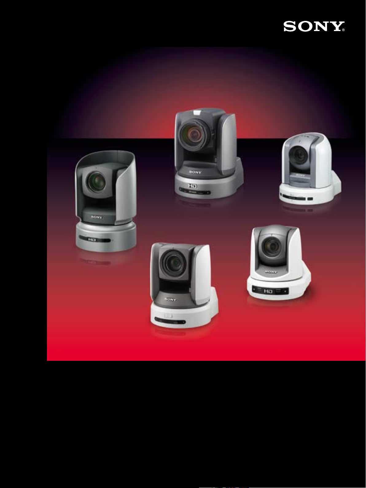
The BRC Series consists of five Pan/Tilt/Zoom (P/T/Z) cameras – the BRC-H900, BRC-H700, BRC-Z700,
BRC-Z330, and BRC-300/300P. They offer wide and smooth pan/tilt/zoom capabilities together with
exceptional picture quality from SD to Full HD images. You can remotely control these cameras using the
RM-BR300 Remote Control Unit. As a flagship model, the BRC-H900 delivers greatest sensitivity (F10) and
horizontal resolution (more than 1,000 TV lines in HD-SDI output) to meet the needs of highly qualityconscious applications. The BRC Series is perfect for a variety of remote video shooting applications, and
each camera integrates easily into a wide range of indoor and outdoor systems.
These features enable more and more users to enjoy the benefits of BRC Series cameras, particularly in
education, broadcast, bridal, and corporate applications. And with their advanced remote capabilities,
these cameras also enable a reduction in manned operation.
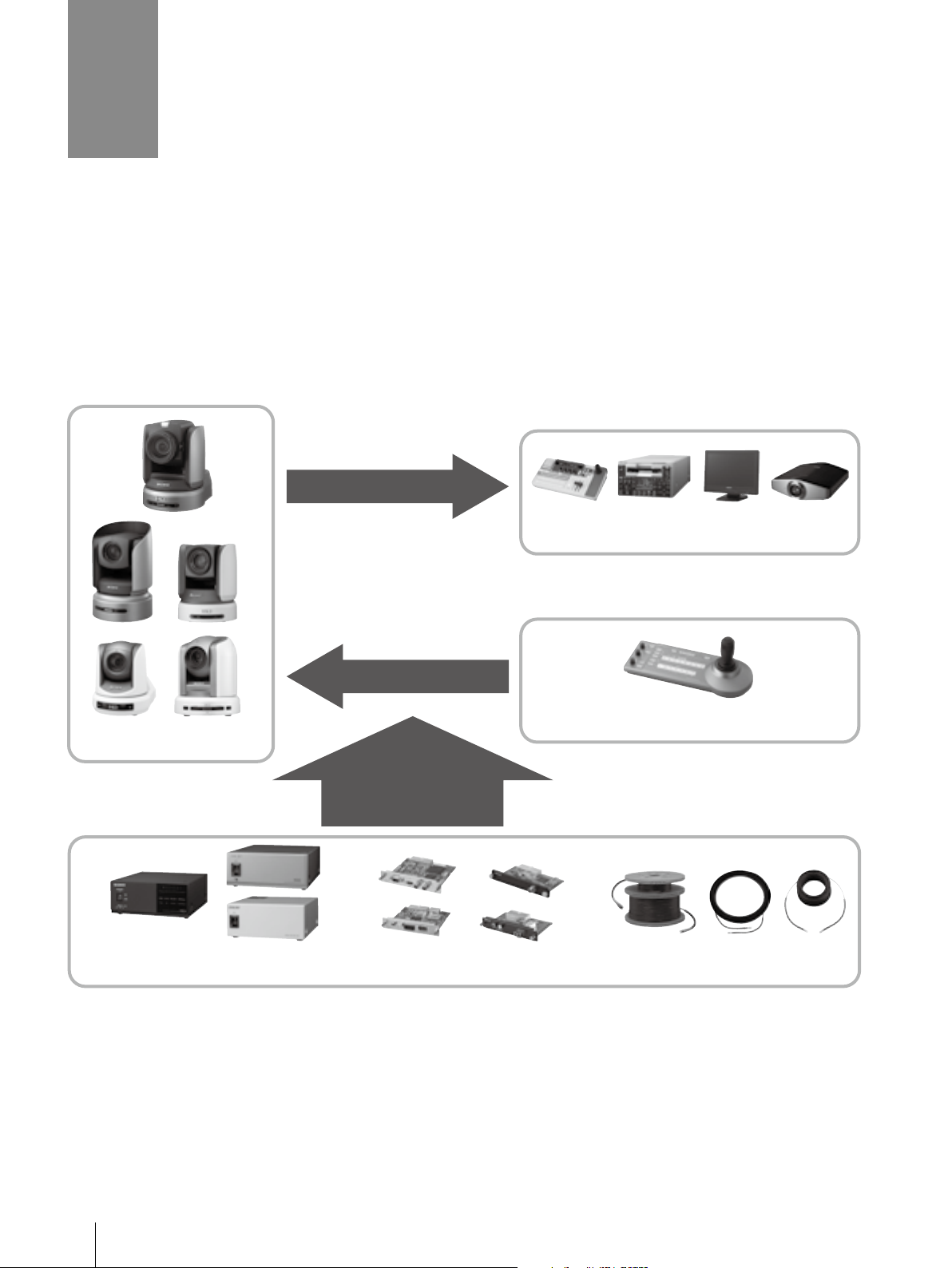
Video Out
Switcher, Recorder, Monitor, Projector, etc.
P/T/Z Color Video Cameras
Optical Multiplex Units Optional Video Cards Optical Fiber Cables
Control
Remote Control Unit
Added Functionality
with
Optional Accessories
*The RM-IP10 is compatible with the BRC-H900, BRC-Z700, and BRC-Z330 only.
4
What is the BRC Series?
Applications
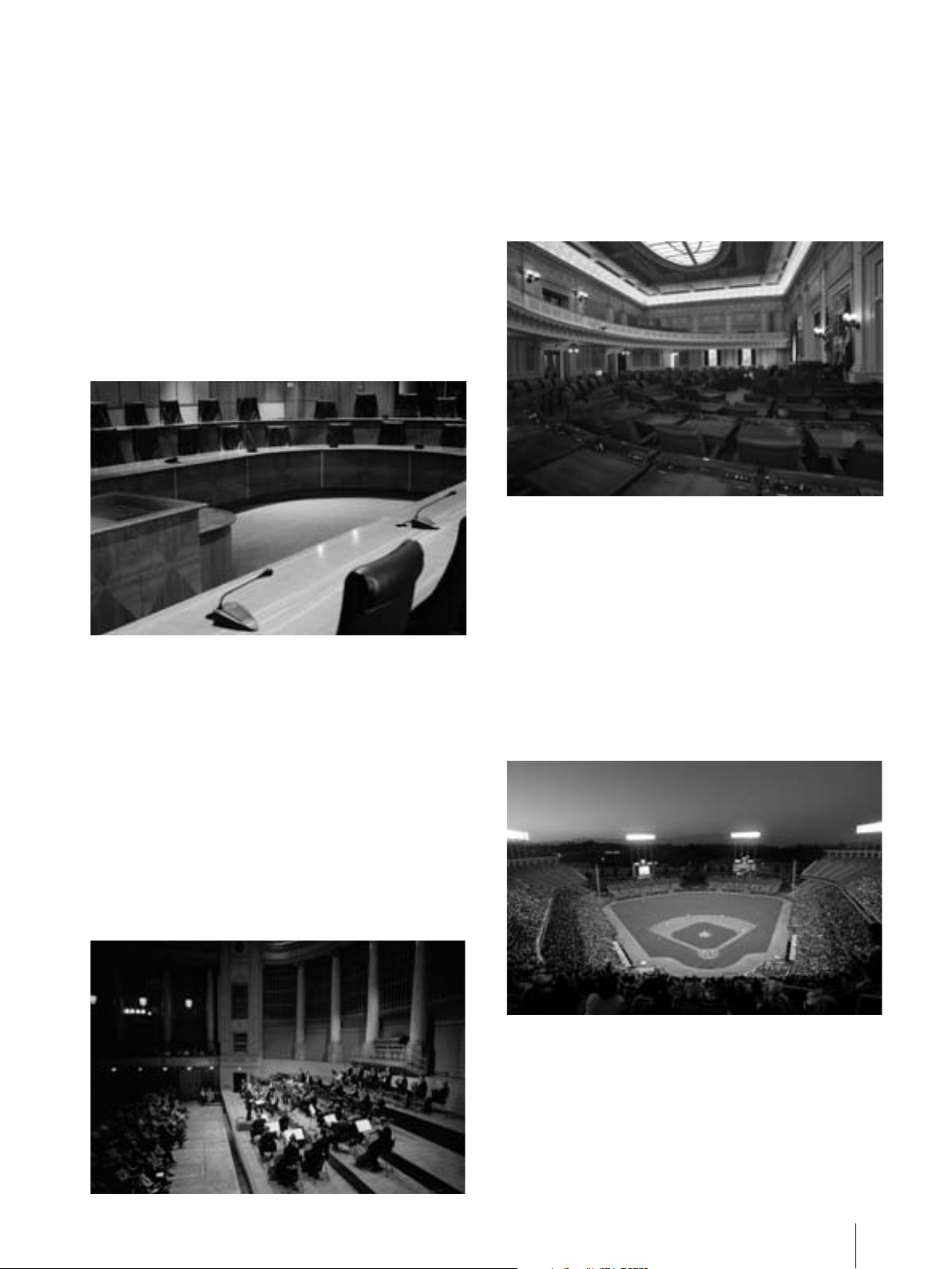
Corporate/Boardroom
BRC Series cameras are excellent for various
business communication applications, such as
videoconferencing, corporate training, and
transmission of managers’ regular speeches. Each
of the cameras in this series offers particular
features and advantages, providing a variety of
cameras for any application. The cameras are
easy to operate and can be quickly reset after
each use simply by touching a button on the
supplied controller – which recalls pre-specified
positions for capturing speech and switching
scenes.
Auditorium/Concert Hall
With its pan/tilt/zoom (P/T/Z) capability, a single
camera can capture a wide shooting range
during an entire live performance, including
audience shots. Therefore, with the BRC Series,
fewer cameras and camera operators are
required, resulting in huge cost savings. These
cameras make it easy to get close-ups of
performers from locations that are typically difficult
for a camera operator to reach. Additionally, each
camera’s compact size and quiet movement
doesn’t distract the audience from the
performance.
City Council
Remotely controlled by the RM-BR300, BRC Series
cameras quickly capture all of the actions at
council meetings or trials. Each camera provides
simple, streamlined operation by offering multiple
presets which pre-define P/T/Z positions.
Sports Events
With high-speed and extremely smooth pan/tilt
movement, BRC Series cameras can follow the
quick, spontaneous flow of sports action. With
cameras installed in high positions, operators can
obtain extensive views of each event, and capture
shots at unique angles, typically very difficult to
achieve with conventional shooting. Also, optical
fiber connection (max. 2,000 m) achieves longdistance data transfer and enables single-operator
broadcasting.
What is the BRC Series?
5
Studio
The BRC Series is also ideal for use in the
broadcast industry. The BRC-H900, BRC-H700,
BRC-Z700, and BRC-Z330 can output HD-SDI
signals*
broadcasters who seek uncompromising picture
quality. With flexible installation, these cameras
can be easily integrated into a working studio with
tripods or ceiling brackets. For the wide angles
required in studio shooting, wide conversion lenses
are available*
benefits, including quiet and smooth P/T/Z
movement, a tally indicator, cost-efficiency, and
more.
*1 The BRC-H700, BRC-Z700, and BRC-Z330 require optional
*2 Wide conversion lenses are available for the BRC-Z700
1
– a necessity for highly demanding
2
. And there are numerous other
video cards.
and BRC-300.
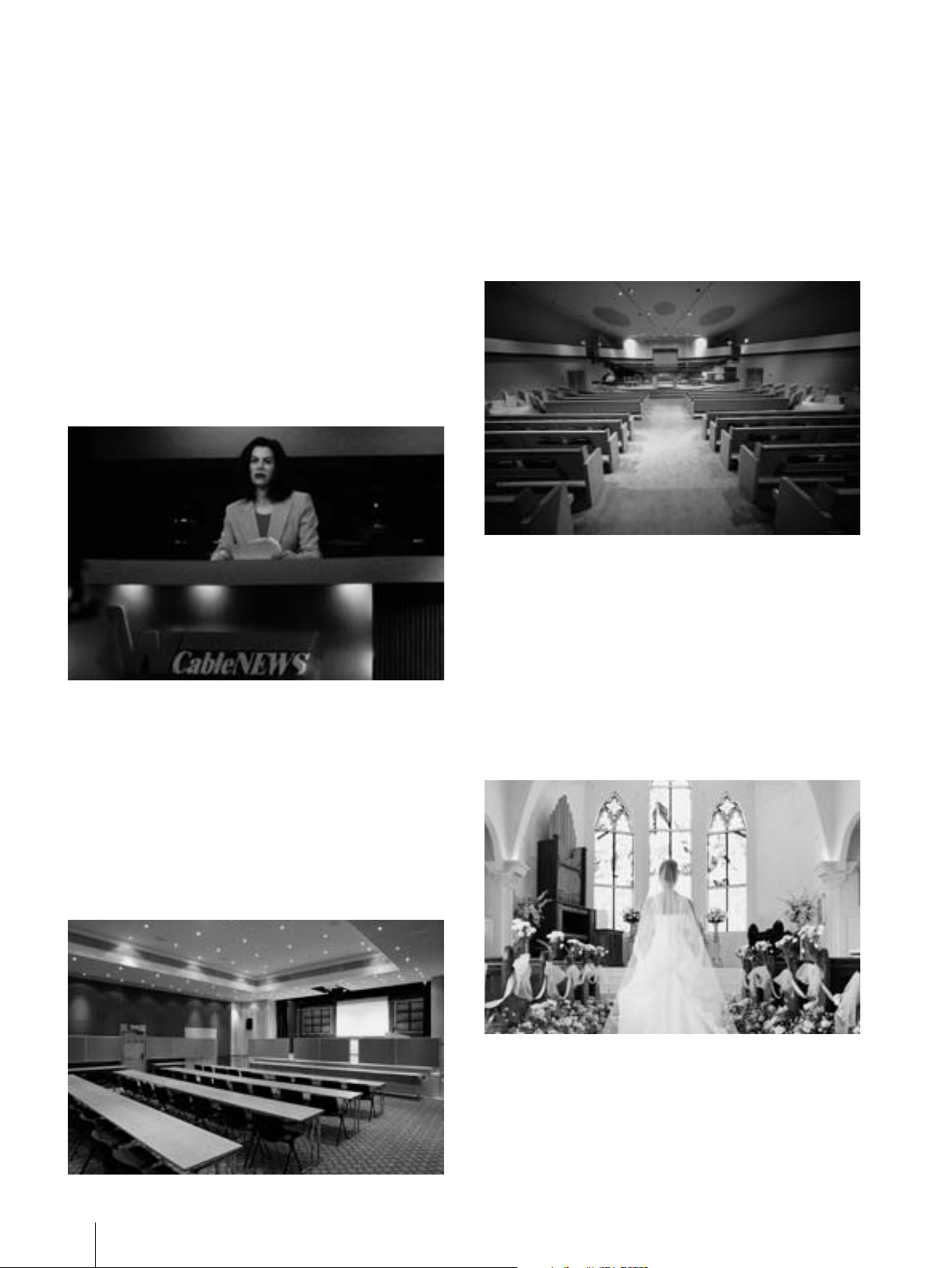
Houses of Worship
By using large screens in combination with highly
sensitive BRC Series cameras, clear video images
can be delivered with accurate color
reproduction. Attendees can become more
involved in the service and follow ongoing events
better than ever before. With a variety of
peripheral components, a range of user-friendly
systems can be designed to suit the size and
budget of every organization.
Education
By deploying BRC Series cameras, teachers can
offer students new educational opportunities
anytime and anywhere. With the real-time
distribution of lectures and other educational
content, academic institutions can deliver
e-learning classes, and professors can efficiently
share their opinions and collaborate via networked
communication.
Weddings
Pre-installed BRC Series cameras are ideal for
capturing wedding ceremonies since their silent
movement will not disturb the ceremony. With
high picture performance and zooming
capabilities, these cameras can capture natural
facial expressions and, for example, the graceful
movements of the bride. Also, due to their
compact and sleek design, these cameras blend
easily into the surrounding environment.
6
What is the BRC Series?
2
Product Lineup
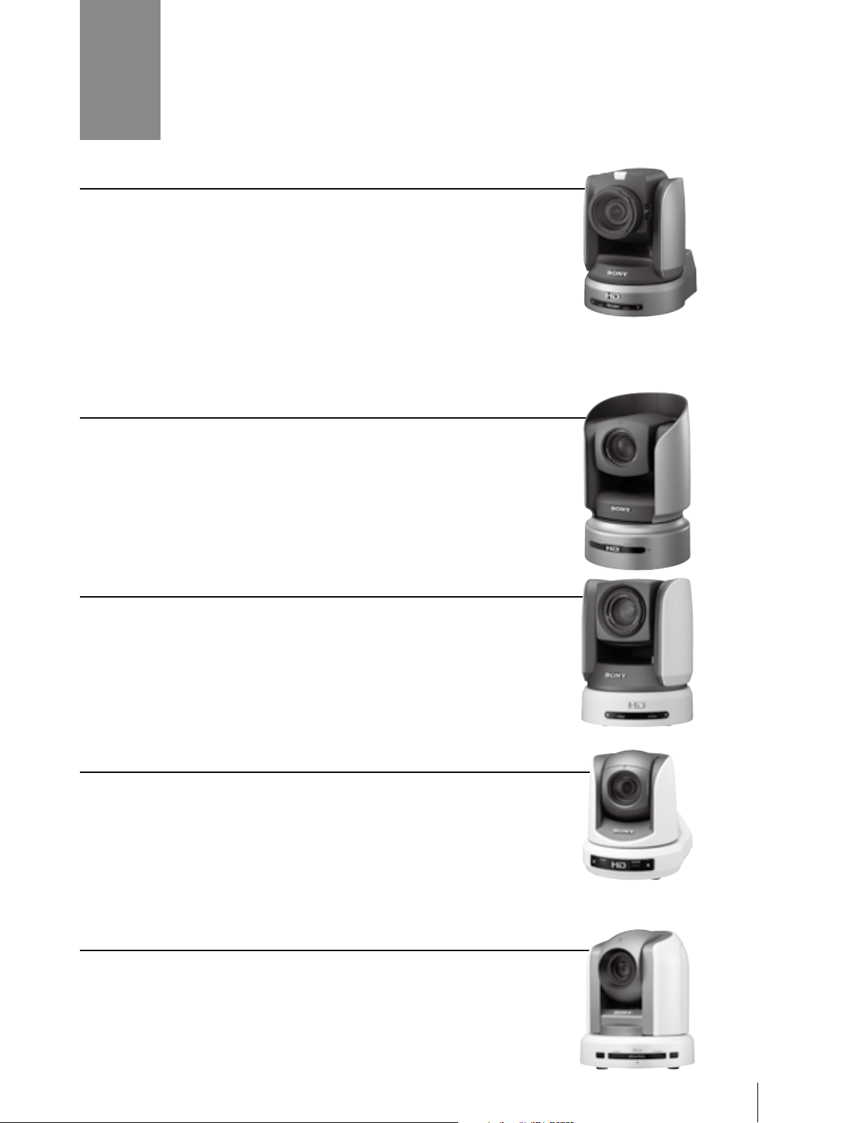
BRC-H900
The BRC-H900 is a flagship model, equipped with three 1/2-type
“Exmor” 3CMOS sensor. This camera offers greatest performance of
minimum illumination, as low as four lux, among BRC series cameras.*
Therefore it delivers excellent quality HD and SD picture even in dark
environment. Furthermore, with the use of RM-IP10 Remote Controller
and BRBK-IP10 IP Control Card, the camera can be controlled through
IP network. This flexibility of installation enables to install up to 112 units
of cameras and up to five units of RM-IP10 controller depending on
customer’s requirements.
* At 50IRE, F1.9, +24 dB.
BRC-H700
Equipped with three 1/3-type HD CCDs, the BRC-H700 offers excellent
picture quality with high sensitivity and a high resolution of 1,070,000
effective pixels. This camera has the best sensitivity of the BRC Series; it
therefore delivers superior performance in dimly lit environments, such
as concert or wedding halls. Moreover, the camera offers the widest
viewing angle of the BRC Series, delivering wider images of each
scene and providing a complete picture of ongoing events.
BRC-Z700
The BRC-Z700 offers a resolution of 1,040,000 effective pixels by
deploying three 1/4-type ClearVid™ CMOS image sensors in
combination with Sony-developed DSP technology. This camera
includes a 20x optical auto-focus zoom lens with an optical image
stabilizer. The perfect choice for long-distance-shooting applications,
such as sporting coverage, this camera provides dual SD/HD outputs,
enabling users to smoothly shift towards adopting a total HD system.
BRC-Z330
Equipped with single 1/3-type 2-megapixel CMOS image sensor, the
BRC-Z330 delivers stunning HD images and SD images. This camera
enables 1080i and 720p to be integrated in various HD systems. It also
outputs SD signals simultaneously for further system flexibility; this is
particularly useful when instigating a system upgrade. Added to this,
the camera’s quiet movement, compact size, light weight, and stylish
design broaden the options when developing ideal applications.
BRC-300/300P
The standard-definition BRC-300 comes equipped with three 1/4.7type Advanced HAD™ CCD sensors. This camera delivers dependable
picture quality and is the best for costefficient SD applications. It can
capture images in 4:3 and 16:9 aspect ratios, the latter providing a
wider viewing angle.
Product Lineup
7
3
The BRC-H900
The BRC-H700
The BRC-Z700
The BRC-Z330
The BRC-300/300P
Optical multiplex card
Optical fiber cable
RM-BR300 Remote Control Unit
Optical Multiplex Unit
(BRU-SF10, BRU-H700, BRU-300/300P)
Video out
Max. 2km
(BRC-H900/BRC-Z330)
Max. 1km
(BRC-H700/BRC-Z700)
Max. 500 m
(BRC-300/300P)
Key Features
All-in-one P/T/Z Design
Stylish design suitable for most
environments
The sleek design can complement almost any
environment, including the interior décor of
houses of worship, wedding halls, public
spaces, and more.
Unobtrusive design ideal for reality
shows and live events
The unobtrusive design of the BRC Series allows
speakers and audiences to concentrate on
discussions and lectures without being
distracted. These inconspicuous cameras help
to capture natural expressions and behavior.
Long-distance Operation Using an Optical Fiber Cable
Cost Efficiency
While each camera in the BRC Series
incorporates CCD or CMOS image sensor, 12x
to 20x zoom lenses, and P/T/Z movements, they
are also reasonably priced, and are ideal for
remote video shooting
applications.
With outstanding functionality and a large number
of peripheral components to choose from, you
can design a variety of user-friendly systems.
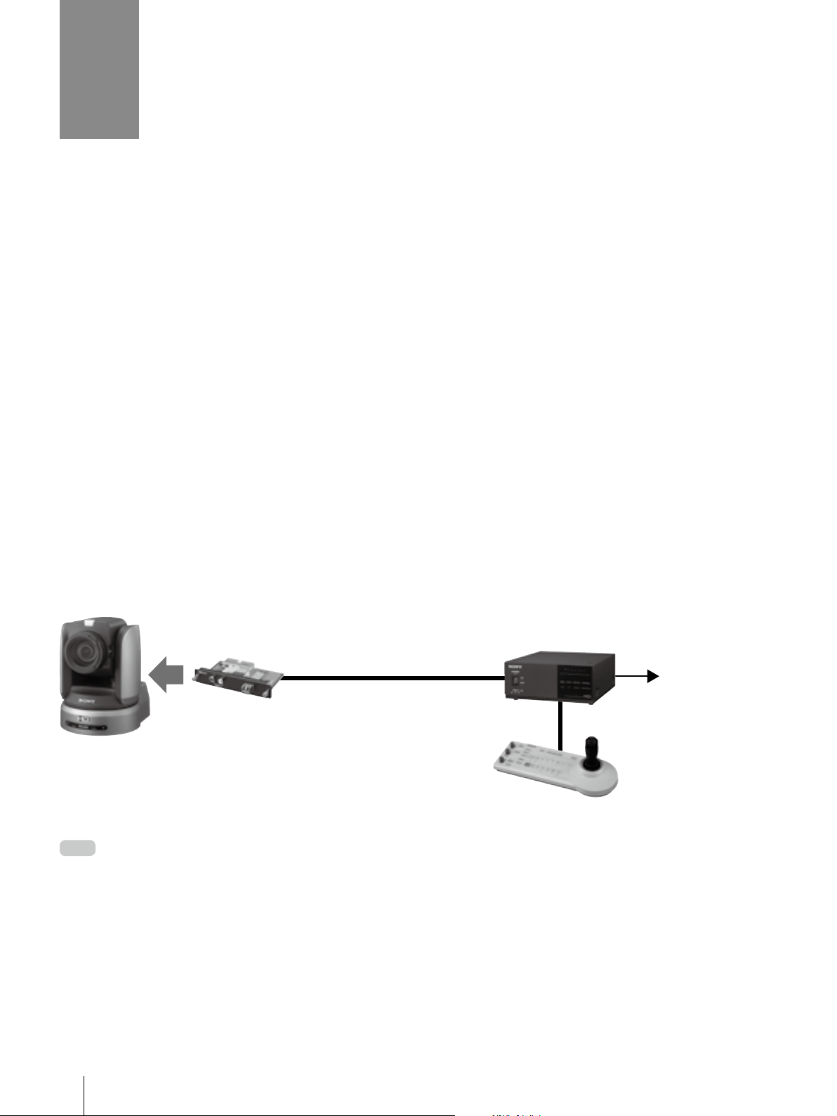
Uncompressed digital data – including video,
external sync, and camera control signals – can
be transmitted over a long distance using an
optical multiplex unit, an optical multiplex card,
and an optical fiber cable. The maximum distance
When using an optical fiber connection, optional video cards are used with the optical multiplex unit to provide a variety
Note
of video signals. In this configuration, camera video outputs are also available from the camera unit itself. When you use
an optional multiplex card inserted into the camera, you cannot control the camera directly by the RM-BR300. You can
control the camera only from the RM-BR300 through the BRU-SF10, BRU-H700 or BRU-300/300P.
between the optical multiplex unit and the
camera is 2000 m for the BRC-H900 and BRC-Z330,
1000 m for the BRC-H700 and BRC-Z700, and 500 m
for the BRC-300/300P.
8
Key Features
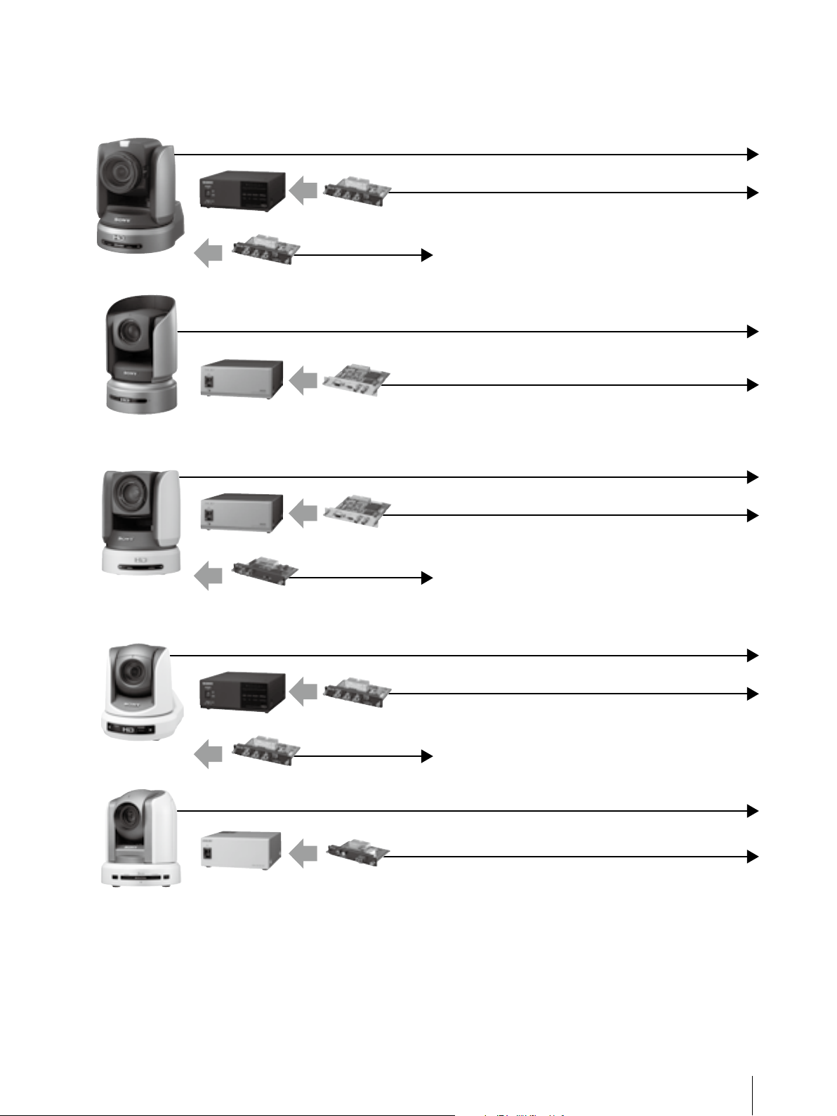
Versatile Video Outputs
By using optional video cards with the BRC Series, a variety of video signals can be output, enabling a wide
range of system configurations.
HD/SD-SDI, HD Component (Y/Pb/Pr), RGB, Composite, Y/C
The BRC-H900
The BRC-H700
The BRC-Z700
BRU-SF10
BRBK-HSD2
BRU-H700
BRU-H700
BRBK-HSD1
BRBK Series
HD/SD-SDI
HFBK Series
HFBK Series
HD/SD-SDI
HD/SD-SDI,
Down Converted SD
HD Component (Y/Pb/Pr), RGB
HD-SDI, i.LINK (HDV), WXGA, XGA, VGA, Down Converted SD
HD Component (Y/Pb/Pr), RGB, Composite, Y/C
HD-SDI, i. LINK (HDV), WXGA, XGA, VGA, Down Converted SD
BRC-Z330
The BRC-300/300P
BRU-SF10
BRBK-HSD2
BRU-300/300P
BRBK Series
HD/SD-SDI
BRBK Series
HD Component (Y/Pb/Pr), RGB, Composite, Y/C
HD/SD-SDI,
Down Converted SD
Composite, Y/C
RGB, SD Component (Y/Cb/Cr), SD-SDI, i. LINK (DV)
Key Features
9
Simultaneous Control of Multiple Cameras
The RM-IP10 Remote Control Unit can operate up to 112 units of BRC cameras (BRC-H900, BRC-Z700, and
BRC-Z330) though an IP network. The BRS-200 Remote Camera Operating Switcher and the RM-BR300
Remote Control Unit can be used to operate up to seven cameras.
RM-IP10
Remote Control Unit (IP)
RM-BR300
Remote Control Unit (VISCA)
BRS-200
Remote Camera
Operating Switcher
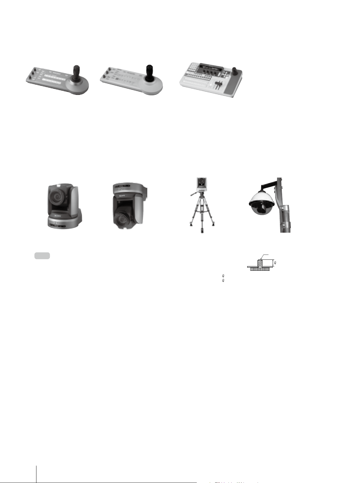
Other Features
Flexible installation
The BRC Series can be placed on a desktop, mounted on the ceiling, used with a tripod, or
installed in an outdoor housing kit, depending on your applications.
Flat surface Ceiling Mount Placed on a tripod Outdoor Housing Kit
BRC Series cameras can be ceiling-mounted with a supplied ceiling
Note
bracket and screws. For use with a tripod, the camera has a standard
¼-20 UNC receptor. For the tripod and the outdoor housing kit, please
contact to the regional headquarters.
= 4.5 – 7 mm
= 0.18 – 0.27 inches
1
/ 4 -20UNC
Multiple presets
The BRC-H900, BRC-H700, BRC-Z700, and, the BRC-Z330 each have sixteen presets and the BRC-300/300P
has six presets to which pre-defined pan/tilt/zoom positions and other parameters can be allocated.
These presets can be recalled at the touch of a button of the BRS-200, the RM-BR300, or the IR remote
commander unit to easily capture video from pre-specified areas.
10
Key Features
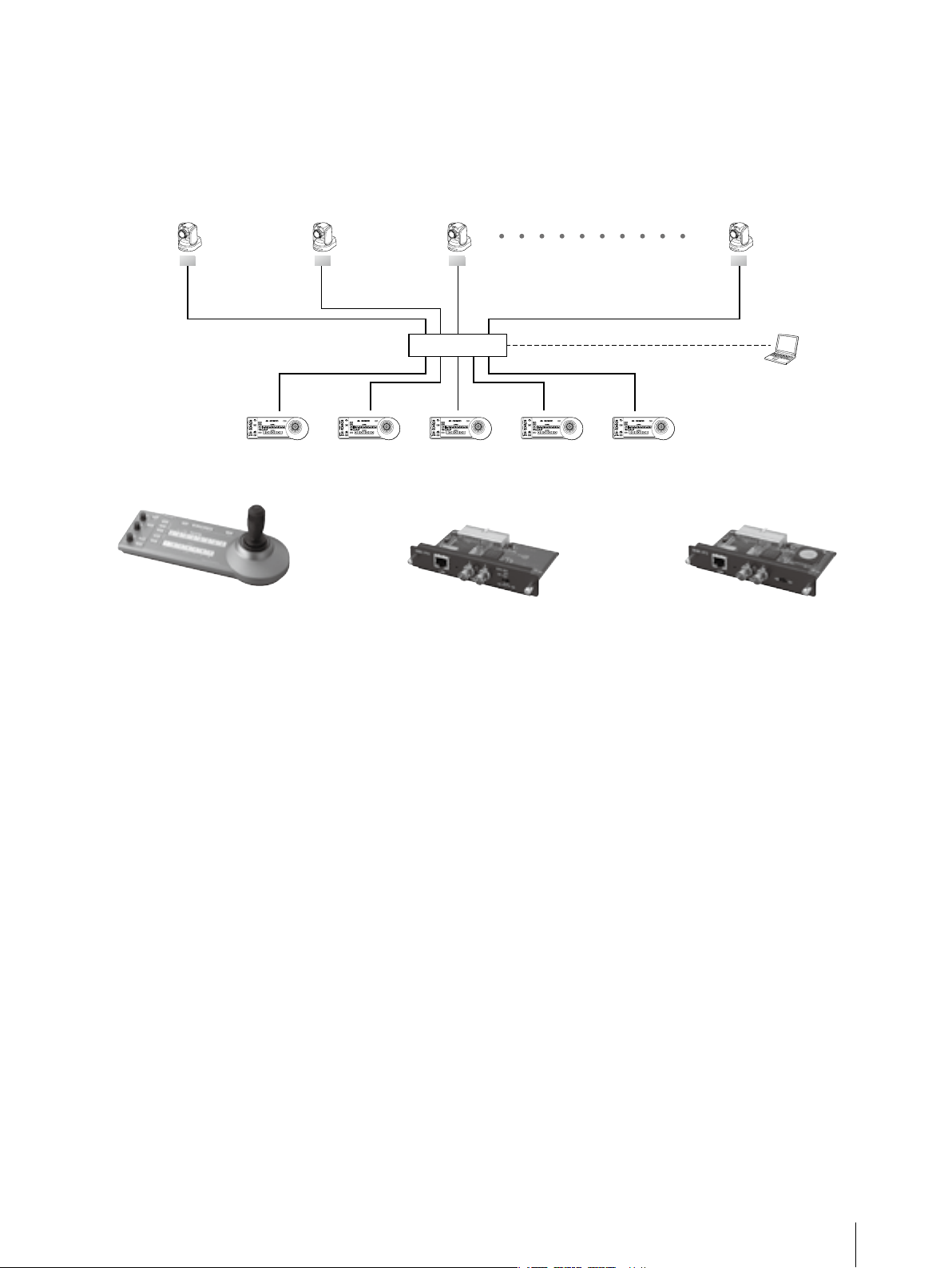
IP Control
The BRC-H900, BRC-Z700, and BRC-Z330 can be controlled though an IP network with the use of an RM-IP10
IP Remote Controller and BRBK-IP10 or BRBK-IP7Z IP Control Card. This functionality allows for flexible
configurations, and enables the installation of up to 112 units of BRC cameras and up to five units of RMIP10 controller depending on customer requirements.
BRC-H900, Z330, Z700
BRBK-IP10 or IP7Z
RM-IP10*
(No. 1)
1
BRC-H900, Z330, Z700
BRBK-IP10 or IP7Z
RM-IP10
(No. 1)
IP Remote Controller
•ComfortableP/T/Zoperationwith
the optical three-axis joystick.
•Versatilecameraadjustmentby
simple panel operation.
•TheuseofIPtechnologyallows
flexible installation and easy
operation.
•Presetfeaturesavescamera
settings (up to 16 positions).
*1: The RM-IP10 is compatible with the
BRC-H900, BRC-Z700, and BRC-Z330 only.
(No. 2)
BRC-H900, Z330, Z700
(No. 3)
BRBK-IP10 or IP7Z
Switching HUB
RM-IP10
(No. 2)
BRBK-IP10*
RM-IP10
(No. 3)
2
RM-IP10
(No. 4)
IP Control Card
•ThecameracanbecontrolledbyIP
connection using the RM-IP10 IP
Remote Controller.
•Outputofimagesshotbythe
camera as HD-SDI signals that
conform to the SMPTE292M serial
digital interface standards or as
down-converted SD-SDI signals that
conform to the SMPTE259M serial
digital interface standards.
*2: The BRBK-IP10 is compatible with the
BRC-H900 and BRC-Z330 only.
BRC-H900, Z330, Z700
(No. 112)
BRBK-IP10 or IP7Z
PC (for System Setting)
RM-IP10
(No. 5)
BRBK-IP7Z*
3
IP Control Card
•ThecameracanbecontrolledbyIP
connection using the RM-IP10 IP
Remote Controller.
•Outputofimagesshotbythe
camera as HD-SDI signals that
conform to the SMPTE292M serial
digital interface standards or as
down-converted SD-SDI signals that
conform to the SMPTE259M serial
digital interface standards.
*3: The BRBK-IP7Z is compatible with the
BRC-Z700 only.
Key Features
11
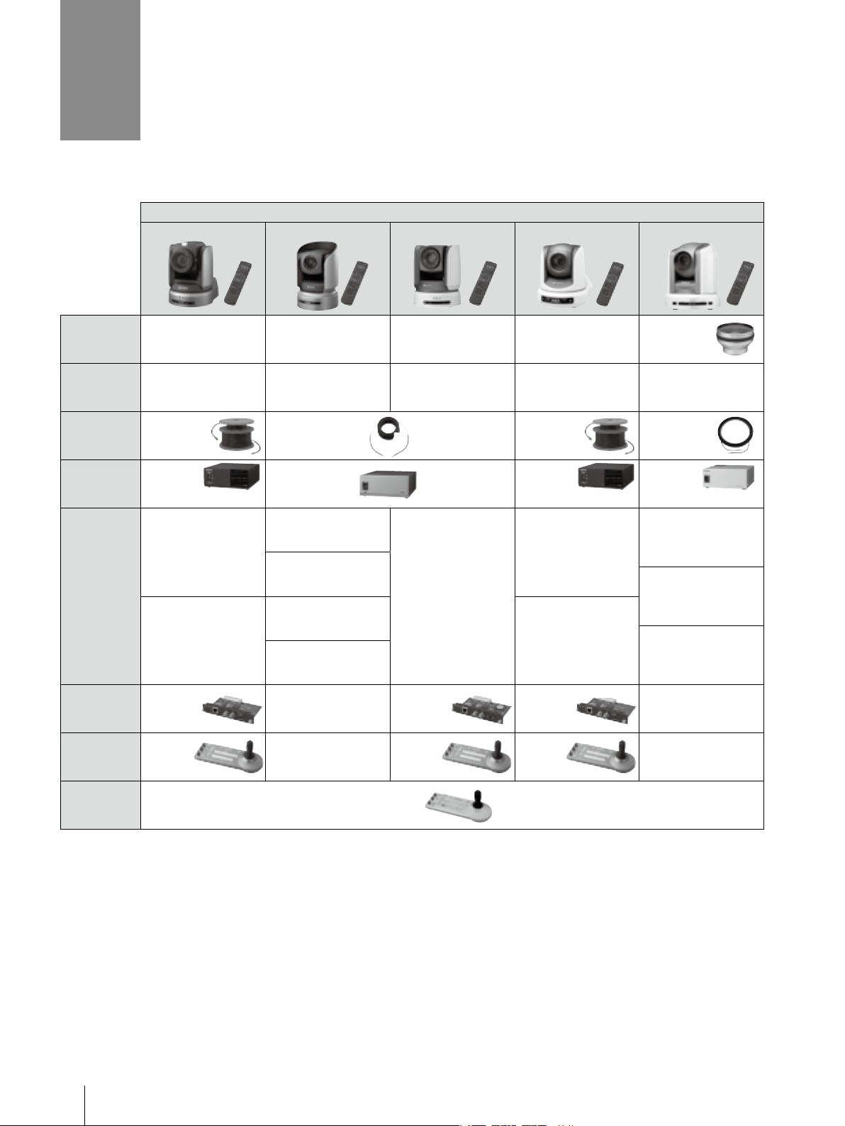
4
System Configuration
You can configure a variety of systems to meet your application needs by choosing HD and/or SD components.
Users can choose either HD or SD system components.
BRC and BRU System
BRC-H900 BRC-H700 BRC-Z700 BRC-Z330 BRC-300/300P
Wide
Conversion
Lens
Optical Multiplex
Card (inserted to
the BRC Series)
BRBK-SF1 BRBK-H700 BRBK-MF1 BRBK-SF1 BRBK-303
— — — — VCL-0737W
Optical Fiber
Cable
Optical
Multiplex
Unit
Optional
Video Card
(inserted to
the BRC
Series)
IP Control
Card
Remote
Control Unit
(IP)
Remote
Control Unit
(VISCA)
CCFC-S200
(Single-mode)
BRU-SF10
(Supports
Single-mode optical fiber)
BRBK-HSD2
HD/SD-SDI
BRBK-SA1
Analog SD Output
BRBK-IP10 — BRBK-IP7Z BRBK-IP10 —
RM-IP10 — RM-IP10 RM-IP10 —
CCFC-M100HG
(Multi-mode)
BRU-H700
(Supports
Multi-mode optical fiber)
HFBK-HD1
HD-SDI, HD Component
(Y/Pb/Pr), RGB
HFBK-SD1
SD-SDI, Composite, Y/C,
SD Component (Y/Cb/Cr), RGB
HFBK-TS1
i.LINK (HDV)
HFBK-XG1
WXGA, XGA, VGA
RM-BR300
BRBK-HSD1
HD-SDI, SD-SDI
CCFC-S200
(Single-mode)
BRU-SF10
(Supports
Single-mode optical fiber)
BRBK-HSD2
HD/SD-SDI
BRBK-SA1
Analog SD Output
CCFC--M100
(Multi-mode)
BRU-300/
300P
(Supports Multi-mode optical fiber)
BRBK-301
Composite, Y/C, SD Component
(Y/Cb/Cr), RGB
BRBK-302
SD-SDI
BRBK-304
i.LINK (DV)
12
System Configuration
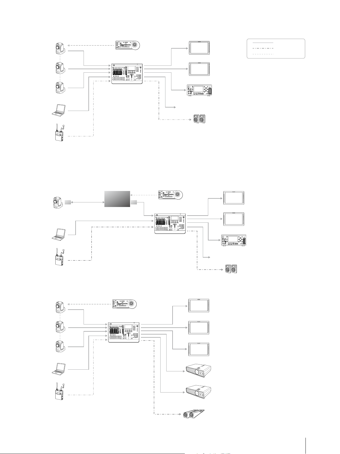
Live Broadcast_01
BRC Cameras
Presentation Material (PC)
Audio Source
RM-BR300
Video Switcher with
Audio Mixer
Monitor (PGM)
Monitor (MV)
Recorder
Broadcast/Streaming
PA
Live Broadcast_02
* There are two types of optical fiber cable (single-mode/Multi-mode). Please refer to the specifications.
Optical
multiplex card
BRC Cameras
Optical fiber
cable*
Optical
Multiplex
Unit
Optional
video card
RM-BR300
Monitor (PGM)
Video
Audio
Control (VISCA)
Presentation Material (PC)
Audio Source
Presentation_01
BRC Cameras
Presentation Material (PC)
RM-BR300
Video Switcher with
Audio Mixer
Monitor (MV)
Video Switcher with
Audio Mixer
Recorder
Broadcast/Streaming
PA
Monitor (PGM)
Monitor (AUX1)
Monitor (MV)
Projector (PGM)
Audio Source
Projector (PGM)
PA
System Configuration
13
5
Location and Function of Parts
5.1 BRC Series of Cameras
The following is a summary of the location and function of BRC-H900, BRC-H700, BRC-Z700, BRC-Z330, and
BRC-300/300P parts.
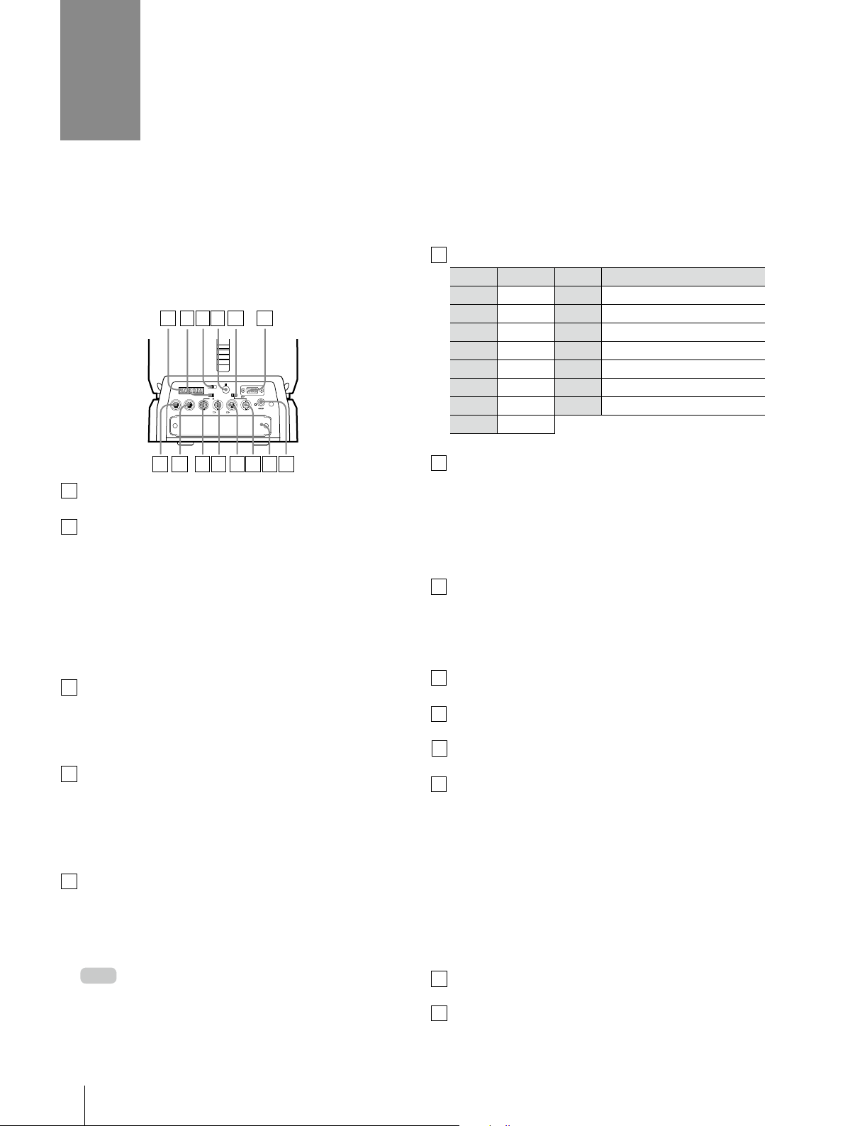
6
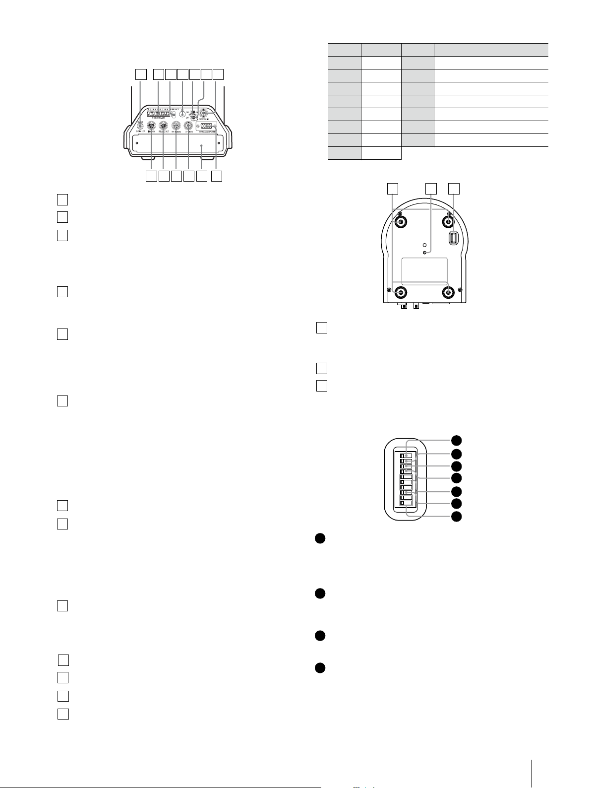
5.1.1 BRC-H900
Rear
1 2 3 4 5 6
1 2 3
1 2 3 4 5 6 7 8 9
IR SELECT
VISCA RS-422
OFF ON HD SD
75
EXT SYNC IN
IN VISCA RS-232 OUT SDI OUT
R
VIDEO S VIDEO
RGB/COMPONENT
DC IN 12V
RGB/COMPONENT connector
Pin No. Signal Pin No. Signal
1 Pr/R 9 NC
2 Y/G 10 GND
3 Pb/B 11 GND
4 GND 12 NC
5 GND 13 HD-OUT
6 GND 14 Tri-level Sync/Bi-level VD
7 GND 15 NC
8 GND
7 8 9 10 11 12 13 14
1
VISCA RS-422 connector
2
75 Ω termination switch
This switch is used when an external sync signal
is used. Set it to OFF when this camera is in the
middle of a daisy-chain connection of multiple
cameras. Set it to ON when the camera is at the
end of a daisy-chain connection or when
nothing is connected to the EXT SYNC IN
connector on the camera.
3
IR SELECT switch
Select the camera number when you operate
multiple cameras with the same Remote
Commander.
4
Remote sensor
This is the sensor for the supplied Remote
Commander.
This remote sensor does not function when IMG
FLIP is set to ON in the SYSTEM menu.
5
HD/SD select switch
Outputs an SD-SDI signal from the SDI
connector when the switch is set to SD, or an
HD-SDI signal from the SDI connector when the
switch is set to HD.
Set the switch before turning the camera on.
Note
7
VISCA RS-232C IN connector
Connect to the RM-BR300 Remote Control Unit
(not supplied). When you connect multiple
cameras, connect it to the VISCA RS-232C OUT
connector of the previous camera in a daisychain connection.
8
VISCA RS-232C OUT connector
When you connect multiple cameras, connect
it to the VISCA RS-232C IN connector of the next
camera in a daisy-chain connection.
9
EXT SYNC IN connector
10
VIDEO connector
11
S VIDEO connector
12
SDI connector
Outputs the video signal from the camera as
an HD/SD-SDI signal.
Supplies down-converted SD-SDI signals that
conform to the SMPTE 259M serial digital
interface standards, or HD-SDI signals that
conform to the SMPTE 292 serial digital interface
standards. Select HD-SDI or SD-SDI signals with
the HD/SD select switch.
13
Card slot
14
Location and Function of Parts
14
DC IN 12V connector
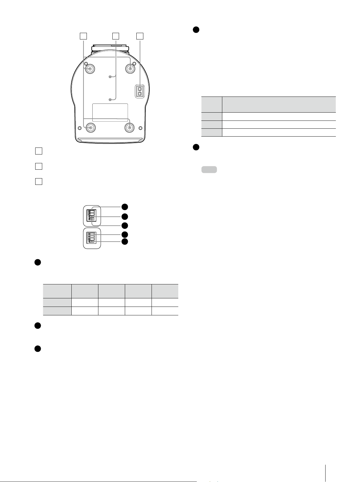
Bottom
15 16 17
15
Ceiling bracket mounting screw holes
16
Tripod screw holes (1/4-20UNC)
17
BOTTOM switches
Setting of the BOTTOM switches
O
1
N
2
3
4
O
1
N
2
3
4
1
2
3
4
5
4
Switch 1, 2, 3 (Camera address selectors)
Set the address of the camera.
Normally set to “0”. With this setting, addresses
are assigned to the cameras automatically in
the connected order by pressing the POWER
button while holding down the RESET button on
the RM-BR300 Remote Control Unit.
You can assign the camera address “1” to “7”
manually by setting these selectors as follows:
Camera
address
Switch 1
Switch 2
Switch 3
5
Switch 4 (Infrared signal output switch)
0 1 2 3 4 5 6 7
OFF ON OFF ON OFF ON OFF ON
OFF OFF ON ON OFF OFF ON ON
OFF OFF OFF OFF ON ON ON ON
Set to ON to enable an infrared signal output,
or OFF to disable the output.
Please note that the same camera address
Note
cannot be assigned to two or more different
cameras. Furthermore, you must set the switches
before you turn on camera power.
1
Switch 1, 2 (signal format selector)
Depending on the setting of the Switch 1, 2, the
signal format is changed as follows:
Signal
format
Switch 1 OFF ON OFF ON
Switch 2 OFF OFF ON ON
2
Switch 3 (RS-232C/RS-422 selector)
1080/
59.94i
1080/50i
720/
59.94p
720/50p
Set to ON for RS-422, or OFF for RS-232C.
3
Switch 4 (Communication baud rate
selector)
Set to ON for 38,400 bps, or OFF for 9,600 bps.
Location and Function of Parts
15
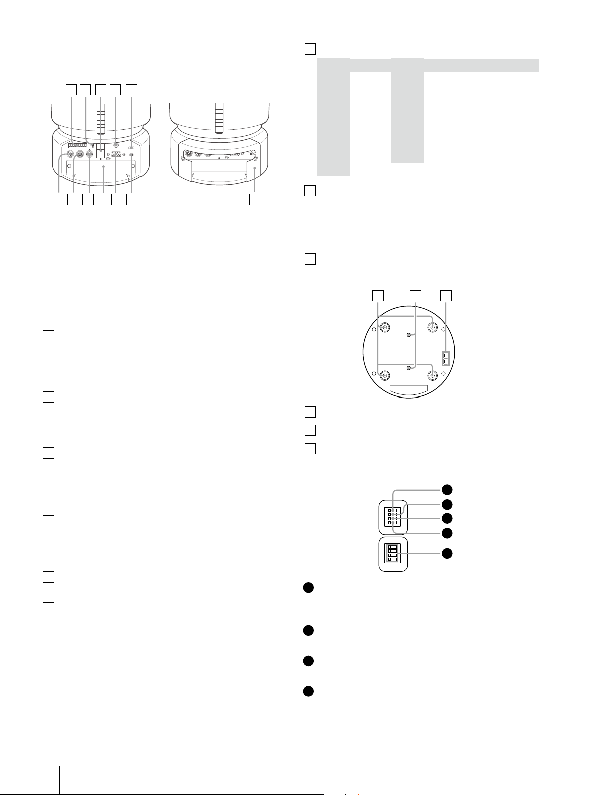
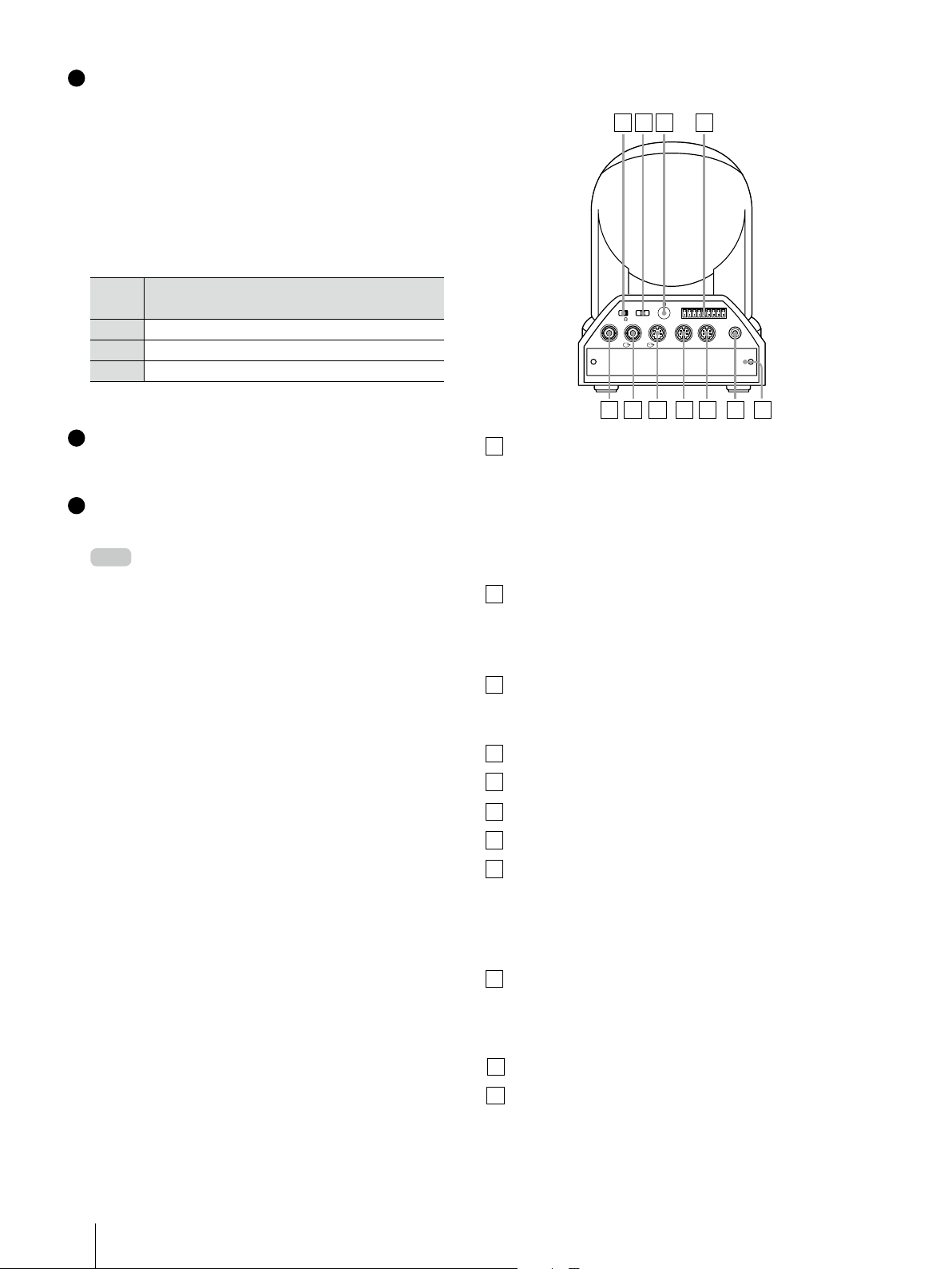
5.1.2 BRC-H700
Rear
1 2 3 4 5
1 2 3 4 5 6 7 8 9
VISCA RS-422
IN VISCA RS-232C OUT
EXT SYNC IN
OFF ON
75
1 2 3
DC IN 12V
IR SELECT
OFF ON
DATA MIX
RGB/COMPONENT
R
6 7 8 9 10 11 12
1
VISCA RS-422 connector
2
75 Ω termination switch
This switch is used when an external sync signal
is utilized. Set it to OFF when the camera is in
the middle of a daisy-chain connection of
multiple cameras. Set it to ON when the
camera is at the end of a daisy-chain
connection.
3
Remote sensor
This is the sensor for the supplied IR Remote
Commander Unit.
With the cable cover attached
1 2 3 4 5 6 7 8 9
OFF ON
75
EXT SYNC IN
DC IN 12V
RGB/COMPONENT
R
VISCA RS-422
IN VISCA RS-232C OUT
OFF ON
10
RGB/COMPONENT connector
Pin No. Signal Pin No. Signal
1 Pr/R 9 NC
2 Y/G 10 GND
3 Pb/B 11 GND
4 GND 12 NC
5 GND 13 HD-OUT
1 2 3
IR SELECT
DATA MIX
6 GND 14 Tri-level Sync/Bi-level VD
7 GND 15 NC
8 GND
11
DATA MIX switch
Set the switch to ON to overlap the menu with
the video signal output from the installed
interface board. Set it to OFF not to overlap the
menu.
12
Cable cover
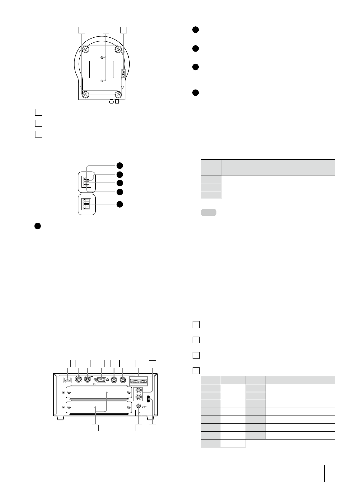
Bottom
13 14 15
4
DC IN 12V connector
5
IR SELECT switch
Selects the camera number when you operate
multiple cameras with the same IR Remote
Commander Unit.
6
VISCA RS-232C IN connector
Connects to the RM-BR300 Remote Control Unit.
When you join multiple cameras, connect it to
the VISCA RS-232C OUT connector of the
previous camera in the daisy chain.
7
VISCA RS-232C OUT connector
When you join multiple cameras, connect it to
the VISCA RS-232C IN connector of the next
camera in the daisy chain.
8
EXT SYNC IN connector
Card slot
9
13
Ceiling bracket mounting screw holes
14
Tripod screw holes
15
BOTTOM switches
(1/4-20UNC)
Setting of the BOTTOM switches
1
O
1
N
2
3
4
O
1
N
2
3
4
Switch 1 (59.94i/50i signal format selector)
1
Set to ON for output of 50i signal format, or OFF
for output of 59.94i signal format.
Switch 2 (RS-232C/RS-422 selector)
2
Set to ON for RS-422, or OFF for RS-232C.
Switch 3 (
3
Communication baud rate selector
Set to ON for 38400 bps, or OFF for 9600 bps.
2
3
4
5
)
16
Location and Function of Parts
4
Switch 4 (Infrared signal output switch)
Set to ON to enable an infrared signal output,
or OFF to disable the output.
Camera address selectors
5
Set the address of the camera. Normally set to
0. With this setting, addresses are assigned to
the cameras automatically in the connected
order by pressing the POWER button while
holding down the RESET button on the
RM-BR300 Remote Control Unit. You can assign
the camera address, 1 to 7, manually by setting
these selectors as follows:
Camera
address
Switch 1
Switch 2
Switch 3
Note
0 1 2 3 4 5 6 7
OFF ON OFF ON OFF ON OFF ON
OFF OFF ON ON OFF OFF ON ON
OFF OFF OFF OFF ON ON ON ON
Switch 4 is not used.
Please note that the same camera address
cannot be assigned to two or more different
cameras. Furthermore, you must set the switches
before you turn on camera power.
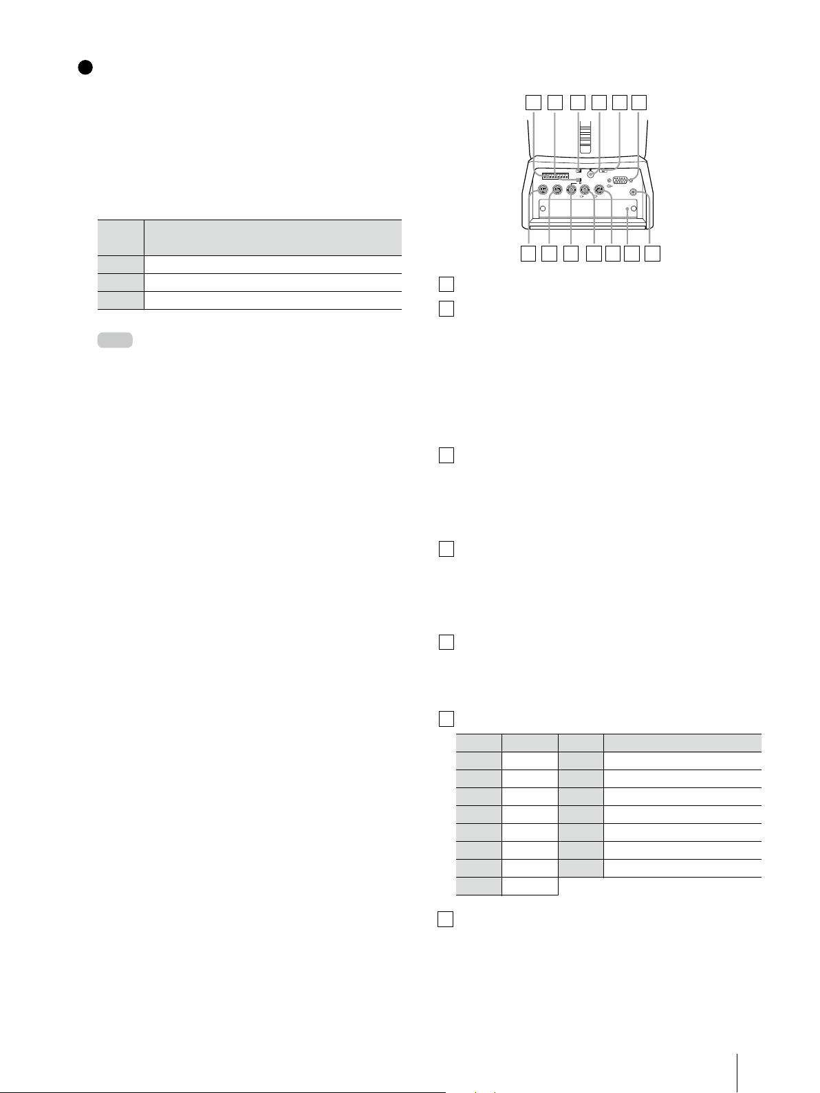
5.1.3 BRC-Z700
Rear
1
VISCA RS-422 connector
2
75 Ω termination switch
This switch is used when an external sync signal
is utilized. Set it to OFF when this camera is in
the middle of a daisy-chain connection of
multiple cameras. Set it to ON when the
camera is at the end of a daisy-chain
connection or when nothing is connected to
the EXT SYNC IN connector on the camera.
3
DATA MIX switch
Set the switch to ON to overlap the menu with
the video signal output from the installed
interface board. Set it to OFF not to overlap the
menu.
1 2 3 4 5 6
R
OFF ON
OFF ON
DATA MIX
IR SELECT
1 2 3
75
RGB/COMPONENT
DC IN 12V
1 2 3 4 5 6 7 8 9
VISCA RS-422
IN VISCA RS-232C OUT S VIDEO
EXT SYNC IN VIDEO
7 8 9 10 11 12 13
4
Remote sensor
This is the sensor for the supplied IR Remote
Commander Unit. This remote sensor does not
function when IMGFLIP is set to ON in the
SYSTEM menu.
5
IR SELECT switch
Selects the camera number when you operate
multiple cameras with the same IR Remote
Commander Unit.
6
RGB/COMPONENT connector
Pin No. Signal Pin No. Signal
1 Pr/R 9 NC
2 Y/G 10 GND
3 Pb/B 11 GND
4 GND 12 NC
5 GND 13 HD-OUT
6 GND 14 Tri-level Sync/Bi-level VD
7 GND 15 NC
8 GND
7
VISCA RS-232C IN connector
Connects to the RM-BR300 Remote Control Unit.
When you join multiple cameras, connect it to
the VISCA RS-232C OUT connector of the
previous camera in the daisy chain.
Location and Function of Parts
17
8
15
VISCA RS-232C OUT connector
When you join multiple cameras, connect it to
the VISCA RS-232C IN connector of the next
camera in the daisy chain.
9
EXT SYNC IN connector
10
VIDEO connector
11
S-VIDEO connector
12
Card slot
13
DC IN 12V connector
Bottom
14 15 16
(Composite out)
5
Camera address selectors
Set the address of the camera. Normally set to
0. With this setting, addresses are assigned to
the cameras automatically in the connected
order by pressing the POWER button while
holding down the RESET button on the
RM-BR300 Remote Control Unit. You can assign
the camera address, 1 to 7, manually by setting
these selectors as follows:
Camera
address
Switch 1
Switch 2
Switch 3
Note
0 1 2 3 4 5 6 7
OFF ON OFF ON OFF ON OFF ON
OFF OFF ON ON OFF OFF ON ON
OFF OFF OFF OFF ON ON ON ON
Switch 4 is not used.
Please note that the same camera address
cannot be assigned to two or more different
cameras. Furthermore, you must set the switches
before you turn on camera power.
14
Ceiling bracket mounting screw holes
Tripod screw holes
16
BOTTOM switches
(1/4-20UNC)
Setting of the BOTTOM switches
1
O
1
N
2
3
4
O
1
N
2
3
4
1
Switch 1 (59.94i/50i signal format selector)
Set to ON for output of 50i signal format, or OFF
for output of 59.94i signal format.
2
Switch 2 (RS-232C/RS-422 selector)
Set to ON for RS-422, or OFF for RS-232C.
3
Switch 3 (
Communication baud rate selector
Set to ON for 38400 bps, or OFF for 9600 bps.
4
Switch 4 (Infrared signal output switch)
Set to ON to enable an infrared signal output,
or OFF to disable the output.
2
3
4
5
)
18
Location and Function of Parts
5.1.4 BRC-Z330
15
Rear
1
DC IN 12V connector
2
VISCA RS-422 connector
3
IR SELECT switch
Select the camera number when you operate
multiple cameras with the same Remote
Commander Unit.
4
Remote sensor
This is the sensor for the supplied Remote
Commander Unit.
5
DATA MIX switch
Set the switch to ON to overlap the menu with
the video signal output from the installed
interface board. Set it to OFF not to overlap the
menu.
6
75 Ω termination switch
This switch is used when an external sync signal
is used. Set it to OFF when this camera is in the
middle of a daisy chain connection of multiple
cameras. Set it to ON when the camera is at the
end of a daisy chain connection or when
nothing is connected to the EXT SYNC IN
connector on the camera.
7
EXT SYNC IN connector
8
VISCA RS-232C IN connector
Connect to the RM-BR300 Remote Control Unit.
When you connect multiple cameras, connect
it to the VISCA RS-232C OUT connector of the
previous camera in the daisy chain
connection.
VISCA RS-232C OUT connector
9
When you connect multiple cameras, connect
it to the VISCA RS-232C IN connector of the next
camera in the daisy chain connection.
10
S VIDEO connector
11
T VIDEO connector
1 2 3 4 5 6 7
8 9 10 11 12 13
Pin No. Signal Pin No. Signal
1 Pr/R 9 NC
2 Y/G 10 GND
3 Pb/B 11 GND
4 GND 12 NC
5 GND 13 HD-OUT
6 GND 14 Tri-level Sync/Bi-level VD
7 GND 15 NC
8 GND
Bottom
14
Ceiling bracket mounting screw holes
* The BRC-Z330 has one Tripod screw hole unlike other
BRC cameras.
14 15 16
Tripod screw hole (1/4-20UNC)
16
BOTTOM switches
Setting of the BOTTOM switches
1
O
1
N
2
3
4
5
6
7
8
9101
B
1
Switch 1 (59.94/50 signal format selector)
Set to ON for output in 1080/50i (720/50P)
signal format, OFF for output in 1080/59.94i
(720/ 59.94P) signal format.
2
Switch 2 (1080i/720p signal format selector)
Set to ON for output in 720p signal format, OFF
for output in 1080i signal format.
3
Switch 3 (
RS-232C/RS-422 selector
Set to ON for RS-422, or OFF for RS-232C.
Switch 4 (Communication baud rate selector)
4
Set to ON for 38400 bps, or OFF for 9600 bps.
2
3
4
5
6
7
)
12
Card slot
13
RGB/COMPONENT connector
Location and Function of Parts
19
5
Switches 5-7 (
Camera address selector
)
Set the address of the camera. Normally set to
“0”. With this setting, addresses are assigned to
the cameras automatically in the connected
order by pressing the POWER button while
holding down the RESET button on the
RM-BR300 Remote Control Unit. You can assign
the camera address “1” to “7” manually by
setting these selectors as follows:
Camera
address
Switch 5
Switch 6
Switch 7
6
Switch 8 (Infrared signal output switch)
0 1 2 3 4 5 6 7
OFF ON OFF ON OFF ON OFF ON
OFF OFF ON ON OFF OFF ON ON
OFF OFF OFF OFF ON ON ON ON
Switch 4 is not used.
Set to ON to enable an infrared signal output,
or OFF to disable the output.
7
Switches 9, 10
These switches are not used.
Please note that the same camera address
Note
cannot be assigned to two or more different
cameras. Furthermore, you must set the switches
before you turn on camera power.
5.1.5 BRC-300/300P
Rear
1
75 Ω termination switch
This switch is used when an external sync signal
is utilized. Set it to OFF when this camera is in
the middle of a daisy-chain connection of
multiple cameras. Set it to ON when the
camera is at the end of a daisy-chain
connection.
2
IR SELECT switch
Selects the camera number when you operate
multiple cameras with the same IR Remote
Commander Unit.
1 2 3 4
1 2 3
OFF ON
IR SELECT
75
EXT SYNC IN
VIDEO S VIDEO
7 8 9 10 11 5 6
R
1 2 3 4 5 6 7 8 9
IN VISCA RS-232C OUT
VISCA RS-422
!
DC IN
12V
3
Remote sensor
This is the sensor for the supplied IR Remote
Commander Unit.
4
VISCA RS-422 connector
5
EXT SYNC IN connector
6
VIDEO connector
7
S-VIDEO connector
8
VISCA RS-232C IN connector
(Composite out)
Connects to the RM-BR300 Remote Control Unit.
When you join multiple cameras, connect it to
the VISCA RS-232C OUT connector of the
previous camera in the daisy chain.
9
VISCA RS-232C OUT connector
When you join multiple cameras, connect it to
the VISCA RS-232C IN connector of the next
camera in the daisy chain.
10
DC IN 12V connector
11
Card slot
20
Location and Function of Parts
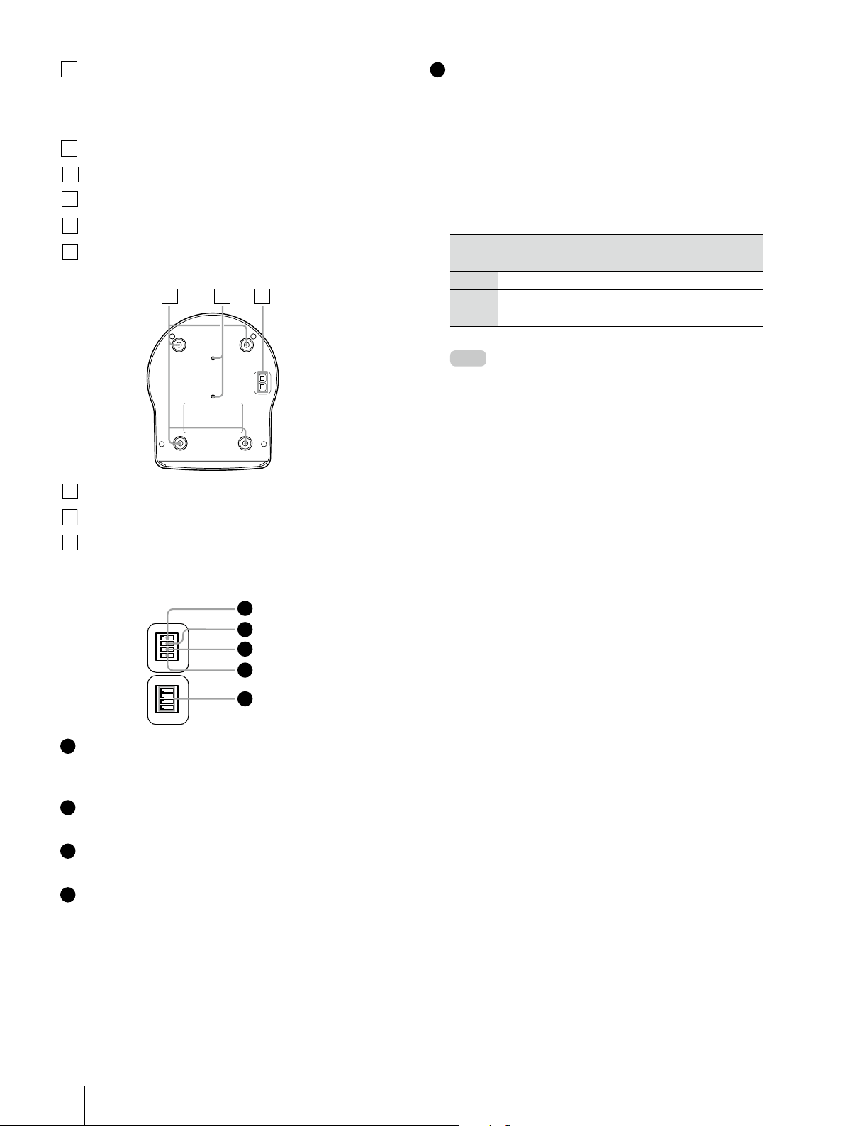
Bottom
12 13 14
Switch 2 (RS-232C/RS-422 selector)
2
Set to ON for RS-422, or OFF for RS-232C.
12
Ceiling bracket mounting screw holes
13
Tripod screw holes
14
BOTTOM switches
(1/4-20UNC)
Setting of the BOTTOM switches
1
O
1
N
2
3
4
O
1
N
2
3
4
1
Switch 1 (No connection)
Always keep it OFF.
2
3
4
5
Switch 3 (
3
Communication baud rate selector
Set to ON for 38400 bps, or OFF for 9600 bps.
Switch 4 (Infrared signal output switch)
4
Set to ON to enable an infrared signal output,
or OFF to disable the output.
Camera address selectors
5
Set the address of the camera. Normally set to
0. With this setting, addresses are assigned to
the cameras automatically in the connected
order by pressing the POWER button while
holding down the RESET button on the
RM-BR300 Remote Control Unit. You can assign
the camera address, 1 to 7, manually by setting
these selectors as follows:
Camera
address
Switch 1
Switch 2
Switch 3
Note
0 1 2 3 4 5 6 7
OFF ON OFF ON OFF ON OFF ON
OFF OFF ON ON OFF OFF ON ON
OFF OFF OFF OFF ON ON ON ON
Switch 4 is not used.
Please note that the same camera address
cannot be assigned to two or more different
cameras. Furthermore, you must set the switches
before you turn on camera power.
)
5.2 Optical Multiplex Units
The following provides information on the location and function of BRU-SF10, BRU-H700 and BRU-300/300P
parts.
With these optical multiplex units, you can transmit uncompressed digital data including video, external
sync, and camera control signals.
1
5.2.1
Rear
BRU-SF10 HD Optical Multiplex
Unit for use with the BRC-H900
and BRC-Z330
1 2 3 4 5 6 7
IN OUT IN OUT
EXT SYNC
CAMERA
RGB/COMPONENT
11 10 9
VISCA
123456789
RS232C
VISCA RS422
L
R
AUDIO OUT
DC 12V
FUNCTION
10
8
1
CAMERA connector
2
EXT SYNC IN connector
3
EXT SYNC OUT connector
4
RGB/COMPONENT connector
Pin No. Signal Pin No. Signal
1 Pr/R 9 NC
2 Y/G 10 GND
3 Pb/B 11 GND
4 GND 12 NC
5 GND 13 HD-OUT
6 GND 14 Tri-level Sync/Bi-level VD
7 GND 15 NC
8 GND
Location and Function of Parts
21
 Loading...