

Page 1

C-456-100-13 (1)
Color Video Camera
Command List
BRC-X1000/H800/H780
© 2016 Sony Corporation
Page 2

Table of Contents
VISCA Commands ................................................3
Overview of VISCA ...........................................3
VISCA Communication Specifications ..............4
VISCA Device Setting Command ......................6
VISCA Command/ACK Protocol ......................7
VISCA Camera-Issued Messages .......................8
VISCA over IP ........................................................9
Overview of VISCA over IP ...............................9
Communication method of VISCA over IP ......10
BRC-X1000/H800/H780 Commands ..................14
Command List (1/5) ..........................................14
Command List (2/5) ..........................................15
Command List (3/5) ..........................................16
Command List (4/5) ..........................................17
Command List (5/5) ..........................................18
Inquiry Command List (1/4) .............................19
Inquiry Command List (2/4) .............................20
Inquiry Command List (3/4) .............................21
Inquiry Command List (4/4) .............................22
Block Inquiry Command List ...........................23
VISCA Command Setting Values ....................29
Pan/Tilt Status Code List ..................................31
Memory Function (Inquiry Commands) ...........32
PTZ TRACE function Record status bulk
inquiry .............................................................32
PRESET MODE settings and PRESET command
behaviors .........................................................33
Camera IP Setting Command .............................34
Revision History ...................................................35
2
Page 3
VISCA1) Commands
Use of control software based upon this command list
may cause malfunction or damage to hardware and
software. We are not liable for any such damage.
Overview of VISCA
In VISCA, the side outputting commands, for example,
a computer, is called the controller, while the side
receiving the commands, such as a BRC-X1000/H800/
2)
H780
seven peripheral devices including this unit can be
connected to a single controller using communication
conforming to the RS-422 standard. The parameters of
RS-422 are as follows.
• Communication speed: 9600 bps/38400 bps
• Data bits : 8
• Start bit : 1
• Stop bit : 1
• Non parity
Flow control using XON/XOFF and RTS/CTS, etc., is
not supported.
, is called the peripheral device. In VISCA, up to
Note
In the same network, all the camera address selectors
should be set to “0” (automatic setting) or all the
selectors should be manually set to “1” to “7”. Do not
mix the automatic and manual settings.
Each VISCA equipment has VISCA IN and VISCA
OUT connectors.
Set the DTR input (the S output of the controller) of
VISCA IN to H when controlling VISCA equipment
from the controller.
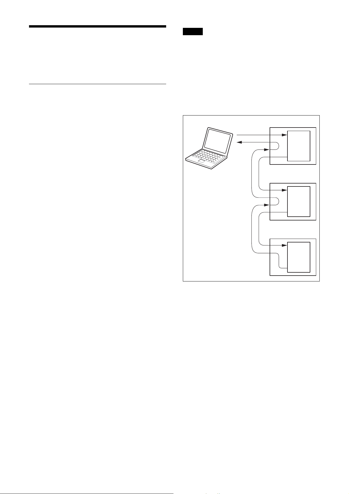
Fig. 1 VISCA network configuration
VISCA Controller
VISCA Equipment
IN
OUT
IN
Peripheral devices are connected in a daisy chain. As
shown in Fig. 1, the actual internal connection is a onedirection ring, so that messages return to the controller
via the peripheral devices. The devices on the network
are assigned addresses.
The address of the controller is fixed at 0.
The addresses of peripheral devices are as follows.
When the camera address selector is set to 0
(automatic setting mode)
The peripheral devices are assigned to the addresses, 1,
2, 3… in the connected order, starting from the one
connected nearest to the controller. These addresses are
set when the controller sends address commands during
initialization of the network.
When the camera address selector is set to 1
through 7 (manual setting mode)
The addresses of the peripheral devices will be set to the
pre-selected numbers. Within a single system, the same
number can be used only once. If an address switch is
used in a setting other than 0, set the address switch on
this connected unit to different numbers.
OUT
IN
OUT
............................................................................................................................................................................................................................
1) VISCA is a protocol developed by Sony for controlling a consumer’s camcorder. “VISCA” is a trademark of Sony Corporation.
2) The product name of this unit, “Color video camera BRC-X1000/H800/H780” is referred to as “the unit” or “color video camera” in
this document. BRC-H780 is the model on sale in China.
3
Page 4
VISCA Communication Specifications
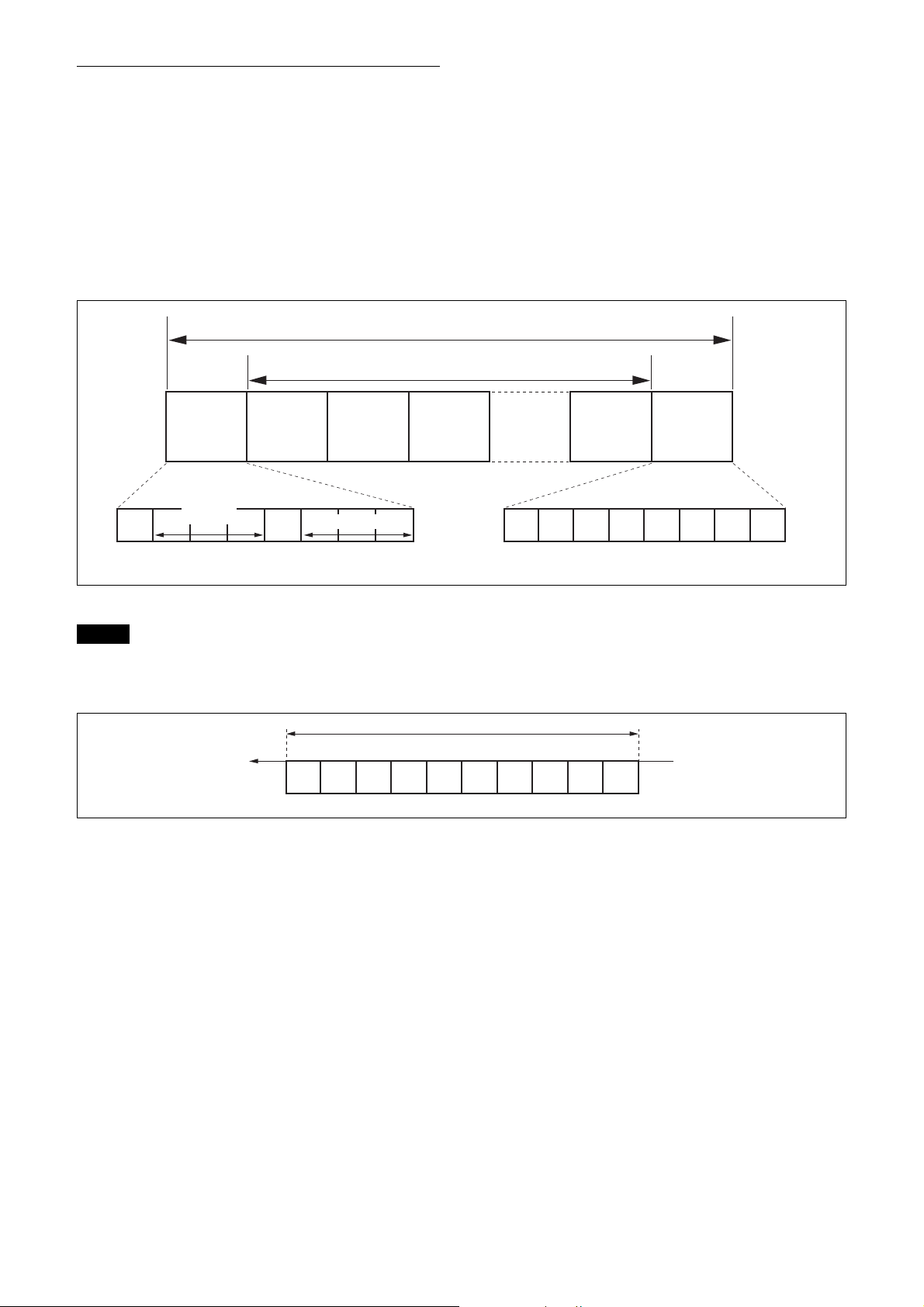
VISCA packet structure
The basic unit of VISCA communication is called a
packet (Fig. 2). The first byte of the packet is called the
header and comprises the sender’s and receiver’s
addresses. For example, the header of the packet sent to
the unit (address 1) from the controller (address 0) is
81H in hexadecimals. Packet sent to the unit (address 2)
Packet (3 to 16 bytes)
is 82H. In the command list, as the header is 8X, input
the address of the unit to X. The header of the reply
packet from the unit assigned address 1 is 90H. The
packet from the unit assigned address 2 is A0H.
Some of the setting commands can be sent to all devices
at one time (broadcast) *.
In the case of broadcast, the header should be 88H in
hexadecimal.
When the terminator is FFH, it signifies the end of the
packet.
* The broadcast function is not available for VISCA over IP.
Header Terminator
Byte 1 Byte 2 Byte 3
Sender’s
10
Bit 7
(MSB)
Note
address
Bit 6 Bit 5 Bit 4 Bit 3 Bit 2 Bit 1 Bit 0
Receiver’s address
Message (1 to 14 bytes)
(LSB)
Fig. 2 Packet structure
Fig. 2 shows the packet structure, while Fig. 3 shows the
actual waveform. Data flow will take place with the LSB
first.
Start
Bit 0 Bit 1 Bit 2 Bit 3 Bit 4 Bit 5
bit
(LSB) (MSB)
1 byte
FF
11111111
Bit 7
Bit 6 Bit 5 Bit 4 Bit 3 Bit 2 Bit 1 Bit 0
(MSB)
Bit 6 Bit 7
Stop
bit.
(LSB)
Fig. 3 Actual waveform for 1 byte.
4
Page 5
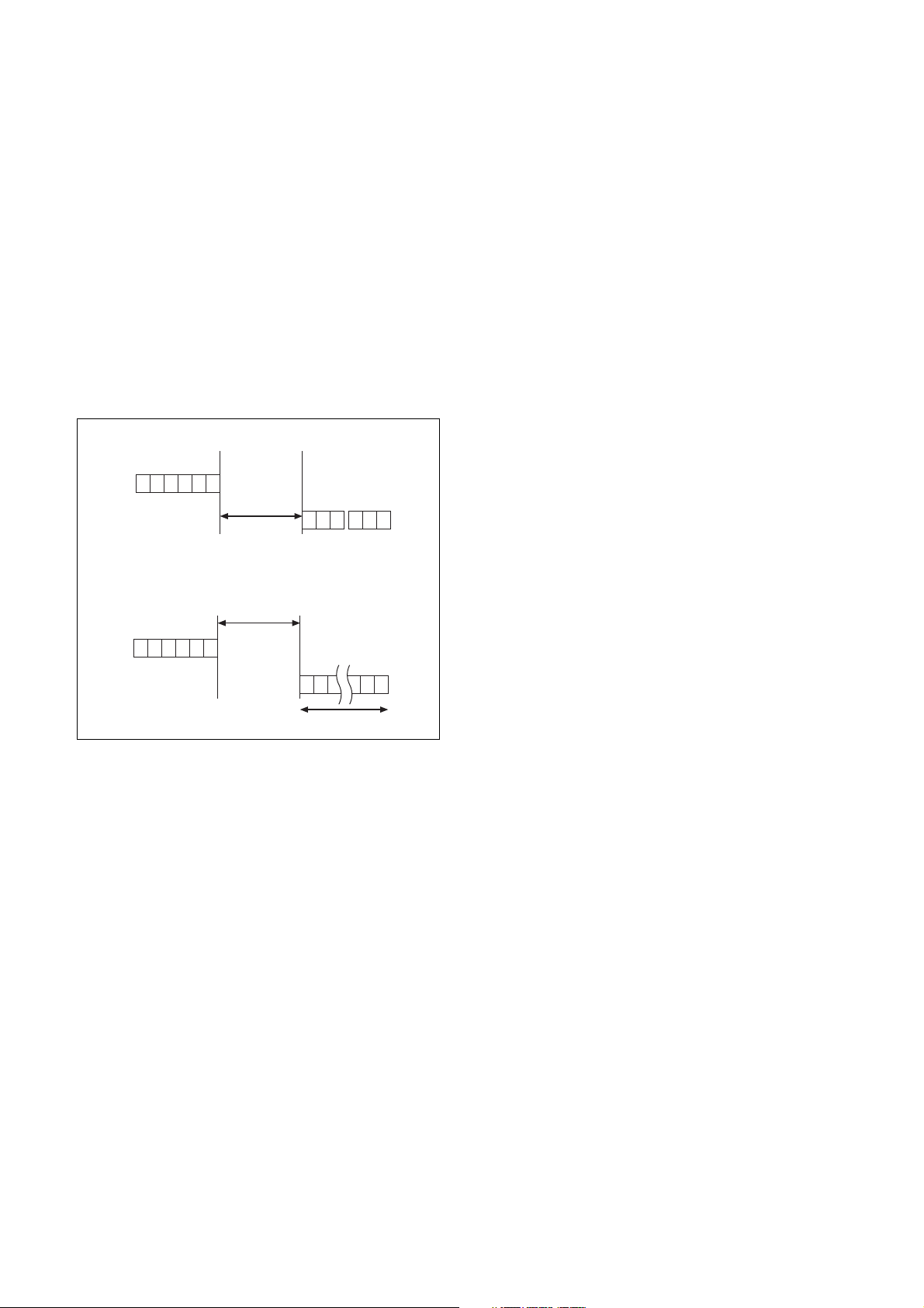
Timing Chart
As VISCA command processing can only be carried out
a maximum of one time in a Vertical (V) cycle, it takes
maximum 4V-cycle time for an ACK/Completion to be
returned.
If the Command and ACK/Completion communication
time is shorter than 1V-cycle time, a command can be
received at every 1V cycle. From this point, if two or
more commands are to be sent successively, wait for a
reply command (an ACK or error message for a general
command, and an inquiry packet for an inquiry
command) of the previous command to be received
before sending the next command.
1V= 16.7 msec (1080/59.94p, 1080/59.94i, 720/59.94p),
20 msec (1080/50p, 1080/50i, 720/50p),
33.4 msec (2160/29.97p (BRC-X1000 only)),
40 msec (2160/25p (BRC-X1000 only)),
41.7 msec (1080/23.98p
*1
This function is not available for BRC-H780.
*1
, 2160/23.98p (BRC-X1000 only))
Responses for commands and inquiries
• ACK message
Returned by the unit when it receives a command. No
ACK message is returned for an inquiry.
• Completion message
Returned by the unit when execution of commands or
inquiries is completed. In the case of inquiry
commands, reply data for the inquiry is contained
after the 3rd byte of the packet. If the ACK message is
omitted, the socket number will contain 0.
Reply Packet Note
Ack X0 4Y FF Y = socket number
Completion (Commands) X0 5Y FF Y = socket number
Completion (Inquiries) X0 5Y ... FF Y = socket number
X = 9 to F: Address of the unit + 8
* Locked to “X = 9” for VISCA over IP.
*
General commands
Command
RxD
TxD
Within 4V
ACK Completion
Inquiry commands
Within 4V
Command
RxD
TxD
Inquiry Packet
16 Bytes
Command and inquiry
• Command
Sends operational commands to the unit.
• Inquiry
Used for inquiring about the current state of the unit.
Command Packet Note
Inquiry 8X QQ RR ... FF QQ1) = Command/Inquiry,
1)
QQ = 01 (Command), 09 (Inquiry)
2)
RR = 00 (Interface), 04 (camera 1), 06 (Pan/Tilter)
X = 1 to 7: Address of the unit*
* Locked to “X = 1” for VISCA over IP.
For actual values to be sent, see Command Lists or
Inquiry Command Lists.
2)
= category code
RR
• Error message
When a command or inquiry command could not be
executed or failed, an error message is returned
instead of a completion message.
Error Packet Description
X0 6Y 01 FF Message length error
X0 6Y 02 FF Syntax Error
X0 6Y 03 FF Command buffer full
X0 6Y 04 FF Command canceled
X0 6Y 05 FF No socket (to be canceled)
X0 6Y 41 FF Command not executable
X = 9 to F: Address of the unit + 8, Y = socket number
* Locked to “X = 9” for VISCA over IP.
Socket number
When command messages are sent to the unit, it is
normal to send the next command message after
receiving the completion message or error message.
However, to deal with advanced uses, the unit has two
sets of buffers (memories) for commands, so that up to
two commands including the commands currently being
executed can be received. (There is a wait longer than a
1V cycle between commands.) However, depending on
the command, it may be necessary to wait until the first
command is completed due to system reasons. When the
unit receives commands, it notifies which command
buffer was used using the socket number of ACK
message.
As the completion message or error message also has a
socket number, it indicates which command has ended.
Even when two command buffers are being used, the
unit management command and some inquiry messages
can be executed.
The ACK message is not returned for these commands
and inquiries, and only the completion message of
socket number 0 is returned.
*
5
Page 6

Command execution cancel
To cancel a command which has already been sent, send
a Cancel command as the next command. To cancel one
of two commands which have been sent, use the cancel
message.
VISCA interface command
• IF_Clear
Clears the command buffer in the unit. When cleared,
the operation currently being executed is not
guaranteed.
Cancel Packet Note
Cancel 8X 2Y FF Y = socket number
X = 1 to 7: Address of the unit, Y = socket number
* Locked to “X = 1” for VISCA over IP.
*
Error message “Command cancelled” will be returned
for this command, but this is not a fault. It indicates that
the command has been cancelled.
Note
To cancel a command when VISCA PAN-TILT Drive
(page 17) is being executed, wait at least 200 msec after
executing. Then send a cancel command to ensure that
PAN-TILT Drive stops effectively.
To execute a PAN-TILT Drive command again, wait at
least 200 msec after the message “Command cancelled”
has appeared.
VISCA Device Setting Command
Before starting control of the unit, make sure to send the
Address command and IF_Clear command using the
broadcast.
For VISCA network administration
• Address*
Sets an address of a peripheral device. Use when
initializing the network, and receiving the following
network change message.
* Not available for VISCA over IP.
Command Packet Reply Packet Note
IF_Clear 8X 01 00 01 FF X0 50 FF
IF_Clear (broadcast)
X = 1 to 7: Address of the unit (For inquiry packet)
X = 9 to F: Address of the unit +8 (For reply packet)
*1 The broadcast function is not available for VISCA over IP.
*2 Locked to “X = 1” for VISCA over IP.
*3 Locked to “X = 9” for VISCA over IP.
*
1
88 01 00 01 FF 88 01 00 01 FF
*2
*3
VISCA interface and inquiry
• CAM_VersionInq
Returns information on the VISCA interface.
Inquiry Inquiry Packet Reply Packet Description
CAM_VersionInq 8X 09 00 02 FF Y0 50 GG GG HH HH JJ JJ KK FF GGGG = Vender ID
0001: Sony
HHHH = Model ID
0519: BRC-X1000
051A: BRC-H800
051B: BRC-H780
JJJJ = ROM revision
KK = Maximum socket # (02)
X = 1 to 7: Address of the unit (For inquiry packet)
X = 9 to F: Address of the unit +8 (For reply packet)
*1 Locked to “X = 1” for VISCA over IP.
*2 Locked to “X = 9” for VISCA over IP.
*1
*2
• Network Change*
Sent from the peripheral device to the controller when
a device is removed from or added to the network. The
address must be re-set when this message is received.
* Not available for VISCA over IP.
Packet Note
Address 88 30 01 FF Always broadcasted.
Network Change X0 38 FF
X = 9 to F: Address of the unit + 8
6
Page 7

VISCA Command/ACK Protocol
Command Command Message Reply Message Comments
General Command 81 01 04 38 02 FF
(Example)
81 01 04 38 FF
(Example)
81 01 04 38 02 FF
(Example)
81 01 04 08 02 FF
(Example)
Inquiry Command 81 09 04 38 FF
(Example)
81 09 05 38 FF
(Example)
Address Set
IF_Clear
(Broadcast)
*1
*1
88 30 01 FF 88 30 02 FF The device address number plus 1 is returned.
88 01 00 01 FF 88 01 00 01 FF The same command is returned.
IF_Clear (For x) 8x 01 00 01 FF y0 50 FF (Completion) ACK is not returned for this command.
Command Cancel 8x 2p FF y0 6p 04 FF
*1 Not available for VISCA over IP.
*2 When the camera address selector is set to an address other than 0, the value x in 88 30 0x FF will be variable.
90 41 FF (ACK)+90 51 FF
(Completion)
Returns ACK when a command has been accepted, or
Completion when a command has been executed.
90 42 FF 90 52 FF
90 60 02 FF
(Syntax Error)
90 60 03 FF
(Command Buffer Full)
90 61 41 FF
(Command Not Executable)
Accepted a command which is not supported or a command
lacking parameters.
Could not accept the command as there are two commands
currently being executed.
Could not execute the command in the current mode.
90 62 41 FF
90 50 02 FF (Completion) Does not return ACK.
90 60 02 FF
Accepted an incompatible command.
(Syntax Error)
Returned when the command of the socket specified is
(Command Cancelled)
cancelled. Completion for the command cancelled is not
returned.
y0 6p 04 FF
(No Socket)
Returned when the command of the specified socket has
already been completed or when the socket number specified
is wrong.
*2
Do not transmit the command (except Address Set, IF_Clear, Command Cancel) when any menu is displayed on the
screen. If displayed, clear the menu first using MENU Display OFF (page 18) Command, and then proceed.
7
Page 8

VISCA Camera-Issued Messages
ACK/Completion Messages
Command Command Message Comments
ACK z0 4y FF
(y: Socket No.)
Completion z0 5y FF
(y: Socket No.)
z = Device address + 8 (Locked to “z = 9” for VISCA over IP.)
Error Messages
Command Command Message Comments
Syntax Error z0 60 02 FF Returned when the command format is different or when a command with
Command Buffer Full z0 60 03 FF Could not accept a command that is received while two commands are
Command Cancelled z0 6y 04 FF
(y: Socket No.)
No Socket z0 6y 05 FF
(y: Socket No.)
Command Not Executable z0 6y 41 FF
(y: Socket No.)
z = Device address + 8 (Locked to “z = 9” for VISCA over IP.)
Returned when the command is accepted.
Returned when the command has been executed.
illegal command parameters is accepted.
currently being executed (two sockets have been used).
Returned when a command which is being executed in a socket specified by
the cancel command is cancelled. The completion message for the command
is not returned.
Returned when no command is executed in a socket specified by the cancel
command, or when an invalid socket number is specified.
Returned when a command cannot be executed due to current conditions.
For example, when a command for controlling the manual focus is received
during the auto focus mode.
Network Change Message*
Command Command Message Comments
Network Change z0 38 FF Issued when power is supplied to the camera.
* Not available for VISCA over IP.
8
Page 9
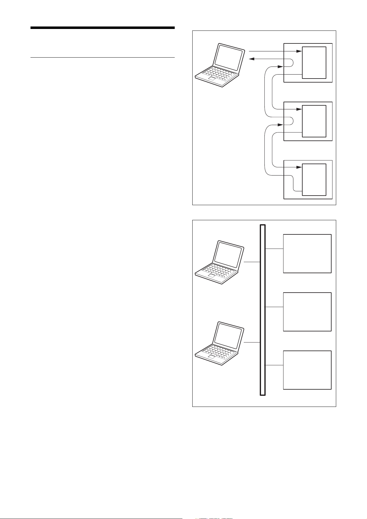
VISCA over IP
Overview of VISCA over IP
With VISCA over IP function, you can control the
camera using VISCA on a controller equipped with IP
communication capabilities via LAN. You can connect
up to 5 controllers simultaneously on the network.
VISCA Controller
VISCA Equipment
IN
OUT
The communication specifications of VISCA over IP are
as follows:
• Interface
RJ-45 10Base-T/100Base-TX (automatically
identifying)
• Internet protocol
IPv4
• Transport protocol
UDP
•IP address
Set by the IP card setting command (page 34)
• Port address
52381
• Delivery confirmation/Retransmission control
Depends on the application
In these instructions, the device outputting commands,
for example, a computer, is called the controller, and the
device receiving the command, such as a BRC series
camera, is called a peripheral device.
The controllers and peripheral devices are connected to
a one-direction ring conforming to RS-422 standards.
On the IP communication connection, the controllers
and peripheral devices are connected by bus through a
LAN.
IN
OUT
IN
OUT
RS422 connection
VISCA Equipment
VISCA Controller
VISCA Equipment
VISCA Controller
VISCA Equipment
Network
IP communication connection
While the IP communication connection, the address of
each device cannot be set in the VISCA message as it is
because the controllers and peripheral devices that are
connected simultaneously are increased. In this case,
addresses of the controllers and peripheral devices that
are set in the VISCA message are locked to 0 (for the
controller) or 1 (for the peripheral device).
9
Page 10
Due to the nature of the IP communication, the use of
some VISCA functions are limited. For details, see
“Camera IP Setting Command” on page 34.
For how to set an IP address of the camera, refer to
“Camera IP Setting Command” on page 34.
Communication method of VISCA over IP
Communication method
VISCA over IP can process the VISCA communication
between the controllers and peripheral devices using the
messages that can be identified on the LAN, and sends/
receives them. Because of this, VISCA over IP is not
concerned about the contents of the communication
between the controllers and peripheral devices.
However, the VISCA communication sequence is
different, depending on the types, as follows.
VISCA device setting command
This is the device setting command from the controller
to the peripheral device as follows.
• Address
Sets the address of the peripheral device, and does not
return a reply to the controller. While using VISCA
over IP, the address command is not sent from the
controller because a Network Change command from
the peripheral device that triggers sending command is
not issued.
•IF_Clear
Sends the reply message to the controller after
clearing, without using VISCA socket.
• CAM_VersionInq
Sends the reply message to the controller, without
using VISCA socket.
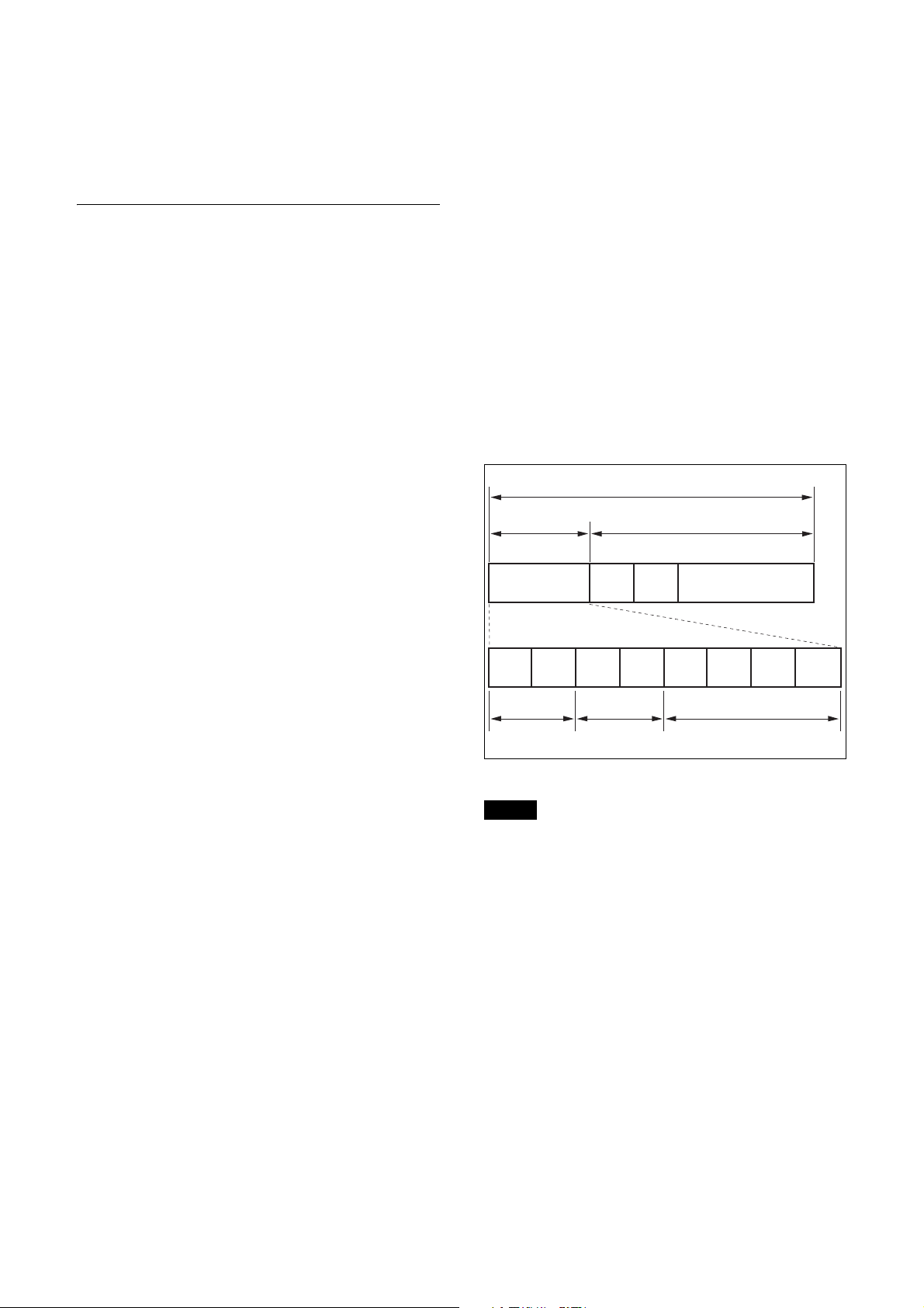
Format
These are the specifications of the message header (8
bytes) and payload (1 to 16 bytes).
VISCA command
This is a command from the controller to the peripheral
device.
When the peripheral device receives this command,
ACK is returned. After completing command
processing, a completion notice is returned. This
command uses the socket of VISCA. The order of
completion notices may be changed if the multiple
commands are sent to the same peripheral device.
VISCA inquiry
This is an inquiry from the controller to the peripheral
device.
When the peripheral device receives this type of
command, the reply for the inquiry is returned. This
command does not use the socket of VISCA. The order
of the replies is not changed if a multiple commands are
sent.
VISCA reply
This is an ACK, completion notice, reply, or error reply
from the peripheral device to the controller.
The classification for sending messages from the
peripheral device to the controller is common.
Message (9 to 24 bytes)
Message header
Byte 0 Byte 1 Byte 2 Byte 3
Payload type
Note
Payload length
Payload (1 to 16 bytes)
Byte 8 Byte 9
Byte 4 Byte 5 Byte 6 Byte 7
Sequence number
Message structure
The actual LAN out method is big-endian, LSB first.
10
Page 11

Payload type
Stores the value (Byte 0 and Byte 1) of the following table on the payload division.
Name Value (Byte 0) Value (Byte 1) Description
VISCA command 0x01 0x00 Stores the VISCA command.
VISCA inquiry 0x01 0x10 Stores the VISCA inquiry.
VISCA reply 0x01 0x11 Stores the reply for the VISCA command and VISCA
inquiry, or VISCA device setting command.
VISCA device
setting command
Control command 0x02 0x00 Stores the control command.
Control reply 0x02 0x01 Stores the reply for the control command.
0x01 0x20 Stores the VISCA device setting command.
Payload length
Stores the number of bytes (1 to 16) of data is stored on
the payload.
Example: When the payload length is 16 bytes.
Byte 2: 0x00
Byte 3: 0x10
Sequence number
The controller stores the sequence number that is added
every time a message is sent. If the sequence number
reaches the limit, next value will be 0. The peripheral
device saves the sequence number in the message from
the controller, and stores the sequence number of the
received message corresponding to the message sent to
the controller.
Payload
Depending on the payload type, the following are stored.
• VISCA command
Stores the packet of the VISCA command.
• VISCA inquiry
Stores the packet of VISCA message.
• VISCA reply
Stores the reply for the command or inquiry (ACK
message, completion message, or error message).
• VISCA device setting command
Stores the packet of the VISCA device setting
command.
• Control command
The following are stored on the payload division of the
control command.
Name Value Description
RESET 0x01 Resets the sequence number
to 0. The value that was set as
the sequence number is
ignored.
ERROR 0x0Fyy yy=01: Abnormality in the
sequence number.
yy=02: Abnormality in the
message (message type)
• Controlled reply
The following are stored on the payload division of the
reply for the control command.
Message Value Description
ACK 0x01 Reply for RESET.
11
Page 12

Delivery confirmation
VISCA over IP uses UDP as a communications protocol of the transport layer. Delivery of messages is not guaranteed
for the UDP communication. Delivery confirmation and retransmission should be performed on the application.
Normally, when the controller sends a message to the peripheral device, the controller sends the new message after
receiving the reply for the last message. You can confirm delivery of messages by managing the time-out waiting for a
reply message sent.
If time out occurs on the controller, loss of one of the following messages is considered:
• Command
• ACK message
• Completion message for the command
• Inquiry
• Reply message for the inquiry
• Error message
• Inquiry of the VISCA device setting command
• Reply message of the VISCA device setting command
If time out occurs on the controller, you can infer the lost message and state of the peripheral device by retransmitting
the message using the same sequence number. The following table shows the received message and status by
retransmission of the lost message, and the reference of correspondence after retransmission for each case. (Except for
the case that a time out occurs for reasons other than loss of message.)
Lost message Received message for
retransmission
Command ACK message Command is performed by
ACK message ERROR (Abnormality in
Completion message
for the command
Inquiry Reply message Inquiry is performed by
Reply message for the
inquiry
Error message Error message Command is not performed.
Inquiry of the VISCA
device setting
command
Reply message of the
VISCA device setting
command
the sequence number.)
ERROR (Abnormality in
the sequence number.)
ERROR (Abnormality in
the sequence number.)
Reply message of the
VISCA device setting
command
ERROR (Abnormality in
the sequence number.)
Status after
retransmission
retransmission.
Command has been
performed.
If only the ACK message is
lost, the completion message
returns.
Command has been
performed.
retransmission.
Inquiry has been performed. If the result by the reply message is needed,
If the error cause eliminates,
normal reply is returns (ACK,
reply message).
Inquiry has been performed
by retransmission.
Inquiry has been performed. If the result by the reply message is needed,
Correspondence after retransmission
Continue processing.
If the result by the completion message is needed,
retransmit by updating the sequence number.
If the result by the completion message is needed,
retransmit by updating the sequence number.
Continue processing.
retransmit by updating the sequence number.
Eliminate the error cause. If normal reply returns,
continue processing.
Continue processing.
retransmit by updating the sequence number.
The BRC series camera has 2 buffers (memories) for the command to deal with advanced uses. When using VISCA
over IP, up to 2 commands (including the current command) can be received. Depending on the message from the
controller to the peripheral device, there are some messages that do not need to guarantee delivery. However, the
peripheral device receives commands from multiple controllers while connected to VISCA over IP. If the multiple
commands are send without waiting for the reply, the possibility of non-execution of the command and errors due to
buffer overflow become high, because of limitations of order to receive commands or execution interval of command.
It may cause efficiency to be reduced substantially.
12
Page 13

Timing chart
Controller Peripheral device
Time out
Timing chart (loss of command)
Controller Peripheral device
Time out
Command seq=100
Command seq=100
Completion seq=100
Command seq=100
Completion seq=100
ACK seq=100
ACK seq=100
Locking the controller’s address of the VISCA
message to 0.
For the same reason as the peripheral device’s address,
the controller’s address of VISCA command is locked to
0. If the controller’s address is set to other than 0, the
peripheral device works without hindrance, and the
reply address from the peripheral device is always set to
0.
Prohibition of specifying the broadcast address
for the VISCA message
Do not use the broadcast address because it requires the
serial communication. Operations under the broadcast
address is set to the command are not guaranteed.
Prohibition of the address for VISCA device
setting command
Do not use this command because it requires the serial
communication. Operations under the address command
is sent are not guaranteed.
VISCA Network Change command is not
supported
This cannot be issued because it requires the serial
communication.
Command seq=100
ERROR
(abnormality in the sequence number)
Command seq=101
Completion seq=101
Timing chart (loss of ACK or completion message)
seq=100
ACK seq=101
Limitation
The following are limitations for VISCA over IP as
compared with the VISCA specifications.
Locking the peripheral device’s address of the
VISCA message to 1
VISCA over IP cannot reflect each address to the
address of the VISCA message because up to 112
peripheral devices and 5 controllers are connected.
Because of this, the peripheral device’s address of
VISCA command is locked to 1 when using VISCA
over IP. If the peripheral device’s address is set to other
than 1 for the VISCA command, the peripheral device
works without hindrance since the peripheral device
recognizes that its address is set to 1.
Expiration time for an on status of the tally lamp
The tally lamp is turned off if not receiving an on
command from any controller for 15 seconds after
receiving an on command of Cmd_Tally.
13
Page 14

BRC-X1000/H800/H780 Commands
Command List (1/5)
Command Set Command Command Packet Comments
EXPOSURE MODE FULL AUTO 8x 01 04 39 00 FF Automatic Exposure mode
MANUAL 8x 01 04 39 03 FF Manual Control mode
SHUTTER Pri 8x 01 04 39 0A FF Shutter Priority Automatic Exposure mode
IRIS Pri 8x 01 04 39 0B FF Iris Priority Automatic Exposure mode
Gain Pri 8x 01 04 39 0E FF
IRIS Reset 8x 01 04 0B 00 FF To return to F2.8 value
Up (Open) 8x 01 04 0B 02 FF
Down (Close) 8x 01 04 0B 03 FF
Direct 8x 01 04 4B 00 00 0p 0p FF pp: Iris Position 05 - 15
GAIN Reset 8x 01 04 0C 00 FF To return to 0 dB
Up 8x 01 04 0C 02 FF
Down 8x 01 04 0C 03 FF
Direct 8x 01 04 4C 00 00 0p 0p FF pp: 00 (–3dB) - 0C (33 dB)
GAIN LIMIT Direct
GAIN POINT On/Off 8x 01 05 0C 0p FF p: 2=On, 3=Off
GAIN POINT
POSITION
SHUTTER Reset 8x 01 04 0A 00 FF Return to the default value depending on the
MAX SHUTTER Direct 8x 01 05 2A 00 0p 0p FF pp: 03 - 15
MIN SHUTTER Direct 8x 01 05 2A 01 0p 0p FF pp: 03 - 15
AE SPEED Direct 8x 01 04 5D pp FF pp: 01 - 30
EXP COMP On/Off 8x 01 04 3E 0p FF p: 2=On, 3=Off
BACK LIGHT On/Off 8x 01 04 33 0p FF p: 2=On, 3=Off
SPOT LIGHT On/Off 8x 01 04 3A 0p FF p: 2=On, 3=Off
VISIBILITY
ENHANCER
IR CUT
*1
FILTER
LOW LIGHT
BASIS
BRIGHTNESS
ND FILTER - 8x 01 7E 01 53 0p FF p: 0=Off, 1=1/4, 2=1/16, 3=1/64
*
Number in ( ) is MENU display values.
*1
This function is not available for BRC-H780.
Direct 8x 01 05 4C 0p 0p FF pp: 01 (0dB) - 09 (24dB)
Up (Fast) 8x 01 04 0A 02 FF
Down (Slow) 8x 01 04 0A 03 FF
Direct 8x 01 04 4A 00 00 0p 0p FF pp: Shutter Position (01 - 15)
Reset 8x 01 04 0E 00 FF To return to 0 value
Up 8x 01 04 0E 02 FF
Down 8x 01 04 0E 03 FF
Direct 8x 01 04 4E 00 00 0p 0p FF pp: 00 - 0E
On/Off 8x 01 04 3D 03 FF Off
Direct 8x 01 04 2D 00 0p 0q 0r 00
On/Off 8x 01 04 01 0p FF p: 2=On (Night), 3=Off (Day)
On/Off 8x 01 05 39 0p FF p: 2=On, 3=Off
Direct 8x 01 05 49 0p FF p: 4 - A
8x 01 04 2C 0p FF
8x 01 04 3D 06 FF On
00 00 00 FF
p: 4 (9dB) - 9 (24dB), F (Off)
frame rate of video output
p: Effect level 0 (Dark) - 6 (Bright)
q: Brightness compensation selection 0 (Very
dark), 1 (Dark),2 (Standard), 3 (Bright)
r: Compensation level 0 (Low), 1 (Mid), 2 (High)
14
Page 15

Command List (2/5)
Command Set Command Command Packet Comments
COLOR WHITE
DETAIL LEVEL Reset 8x 01 04 02 00 FF To return to 7 (0) value
*
Number in ( ) is MENU display values.
BALANCE
ONE PUSH
TRIGGER
R.GAIN Reset 8x 01 04 03 00 FF To return to 80 (0) value
B.GAIN Reset 8x 01 04 04 00 FF To return to 80 (0) value
SPEED 8x 01 04 56 0p FF p: speed 1 (Slow) - 5 (Fast)
OFFSET Reset 8x 01 7E 01 2E 00 00 FF To return to 7 (0) value
CHROMA
SUPPRESS
MATRIX Select 8x 01 7E 01 3D 0p FF p: Matrix Setting (2=STD, 3=OFF, 4=HIGH SAT,
LEVEL Reset 8x 01 04 09 00 FF To return to 4 value
PHASE Reset 8x 01 04 0F 00 FF To return to 7 (0) value
R-G Direct 8x 01 7E 01 7A 0p 0p FF pp: 00 (–99) - 63 (00) - C6 (+99)
R-B Direct 8x 01 7E 01 7B 0p 0p FF pp: 00 (–99) - 63 (00) - C6 (+99)
G-R Direct 8x 01 7E 01 7C 0p 0p FF pp: 00 (–99) - 63 (00) - C6 (+99)
G-B Direct 8x 01 7E 01 7D 0p 0p FF pp: 00 (–99) - 63 (00) - C6 (+99)
B-R Direct 8x 01 7E 01 7E 0p 0p FF pp: 00 (–99) - 63 (00) - C6 (+99)
B-G Direct 8x 01 7E 01 7F 0p 0p FF pp: 00 (–99) - 63 (00) - C6 (+99)
MODE Direct 8x 01 05 42 01 0p FF p: Auto=0, Manual=1
BANDWIDTH Direct 8x 01 05 42 02 0p FF p: Band width 0 - 4
CRISPENING Direct 8x 01 05 42 03 0p FF p: Crispening 0 - 7
H/V BALANCE Direct 8x 01 05 42 04 0p FF p: 5 - 9
B/W BALANCE Direct 8x 01 05 42 05 0p FF p: 0 - 4
LIMIT Direct 8x 01 05 42 06 0p FF p: 0 - 7
HIGHLIGHTDE
TAIL
SUPERLOW Direct 8x 01 05 42 08 0p FF p: 0 - 7
Auto1 8x 01 04 35 00 FF
Indoor 8x 01 04 35 01 FF
Outdoor 8x 01 04 35 02 FF
One Push WB 8x 01 04 35 03 FF
Auto2 8x 01 04 35 04 FF
Manual 8x 01 04 35 05 FF
One Push
Trigger
Up 8x 01 04 03 02 FF
Down 8x 01 04 03 03 FF
Direct 8x 01 04 43 00 00 0p 0p FF pp: 00 (–128) - 80 (0) - FF (128)
Up 8x 01 04 04 02 FF
Down 8x 01 04 04 03 FF
Direct 8x 01 04 44 00 00 0p 0p FF pp: 00 (–128) - 80 (0) - FF (128)
Up 8x 01 7E 01 2E 00 02 FF
Down 8x 01 7E 01 2E 00 03 FF
Direct 8x 01 7E 01 2E 01 0p FF p: 0 (–7) - 7 (0) - E (+7)
- 8x 01 04 5F 0p FF p: 0 (Off), 1 (Weak) - 3 (Strong)
Up 8x 01 04 09 02 FF
Down 8x 01 04 09 03 FF
Direct 8x 01 04 49 00 00 00 0p FF p: 0 (0) - E (14)
Up 8x 01 04 0F 02 FF
Down 8x 01 04 0F 03 FF
Direct 8x 01 04 4F 00 00 00 0p FF p: 0 (–14 degrees) - E (+14 degrees)
Up 8x 01 04 02 02 FF
Down 8x 01 04 02 03 FF
Direct 8x 01 04 42 00 00 0p 0p FF pp: Aperture Gain 00 - 0F
Direct 8x 01 05 42 07 0p FF p: 0 - 4
8x 01 04 10 05 FF One Push WB Trigger
5=FL LIGHT, 6=MOVIE, 7=STILL,
8=CINEMA, 9=PRO, A=ITU709, B=B/W)
15
Page 16

Command List (3/5)
Command Set Command Command Packet Comments
KNEE KNEE SETTING On/Off 8x 01 7E 01 6D 0p FF p: 2=On, 3=Off
KNEE MODE - 8x 01 7E 01 54 0p FF p: 0=Auto, 4=Manual
KNEE SLOPE Direct 8x 01 7E 01 6F 0p 0p FF pp: Knee Slope 00 - 0E
KNEE POINT Direct 8x 01 7E 01 6E 0p 0p FF pp: Knee Point 00 - 0C
GAMMA MODE - 8x 01 04 5B 0p FF p: GAMMA Setting (0=STD, 1=STRAIGHT,
2=PATTERN, 8=MOVIE, 9=STILL, A=CINE1,
B=CINE2, C=CINE3, D=CINE4, E=ITU709)
PATTERN Direct 8x 01 05 5B 0p 0p 0p FF ppp: 001 - 200
OFFSET Direct 8x 01 04 1E 00 00 00 0p 0q
0q FF
LEVEL Direct 8x 01 7E 01 71 0p 0p FF pp: 00 - 0E
BLACK
Direct 8x 01 7E 01 72 0p 0p FF pp: 00 - 0E
GAMMA LEVEL
BLACK
Direct 8x 01 05 5C 0p FF p: Correction range 0 (Low), 1 (Mid), 2 (High)
GAMMA
RANGE
BLACK LEVEL Reset 8x 01 7E 04 15 00 FF To return to 30 (0) value
Up 8x 01 7E 04 15 02 FF
Down 8x 01 7E 04 15 03 FF
Direct 8x 01 7E 04 45 0p 0p FF pp: 00 (–48) - 60 (48)
PICTURE
MODE - 8x 01 7E 04 5F 0p FF p: Picture profile setting (0=PP1, 1=PP2,
PROFILE
FLICKER
MODE On 8x 01 04 32 0p FF p:2=On, 3=Off
REDUCTION
NOISE
MODE LEVEL - 8x 01 04 53 pp FF pp: NR Setting 00 (Off), 01 (Weak) - 05 (Strong),
REDUCTION
2D NR/3D NR
Direct 8x 01 05 53 0p 0q FF p: 2D NR Level 0 (Off), 1 (Weak) - 5 (Strong)
MANUAL
SETTING
ZOOM STOP - 8x 01 04 07 00 FF
TELE
- 8x 01 04 07 02 FF
(STANDARD)
WIDE
- 8x 01 04 07 03 FF
(STANDARD)
TELE
- 8x 01 04 07 2p FF p: 0 (Low) - 7 (High)
(VARIABLE)
WIDE
- 8x 01 04 07 3p FF p: 0 (Low) - 7 (High)
(VARIABLE)
DIRECT - 8x 01 04 47 0z 0z 0z 0z FF zzzz:
p: Offset polarity 0 (+), 1 (–)
qq: Offset width 00 - 40
2=PP3, 3=PP4, 4=PP5, 5=PP6)
7F (Advanced)
q: 3D NR Level 0 (Off), 1 (Weak) - 5 (Strong)
0000 (wide) to 4000 (optical tele) to 5580 (Clear
Image Zoom tele 4K)
CLEAR IMAGE
ZOOM
TELE CONVERT
- 8x 01 04 06 03 FF OFF
8x 01 04 06 04 FF ON
- 8x 01 7E 04 36 0p FF p: 2=Double, 3=Off
MODE
*
Number in ( ) is MENU display values.
*1
Cannot be used when the signal format is other than 1080/29.97p, 1080/25p, or 1080/23.98p.
16
0000 (wide) to 4000 (optical tele) to 6000 (Clear
Image Zoom tele FHD)
*1
Page 17

Command List (4/5)
Command Set Command Command Packet Comments
FOCUS MODE - 8x 01 04 38 02 FF Auto Focus
MANUAL
FOCUS
AUTO/
MANUAL
TOGGLE
STOP - 8x 01 04 08 00 FF
FAR
(STANDARD
SPEED)
NEAR
(STANDARD
SPEED)
FAR
(VARIABLE
SPEED)
NEAR
(VARIABLE
SPEED)
DIRECT Direct 8x 01 04 48 0p 0p 0p 0p FF pppp: F000 (Near) - 0000 (Far)
ONE PUSH
TRIGGER
FOCUS ∞ - 8x 01 04 18 02 FF
NEAR LIMIT Direct 8x 01 04 28 0p 0p 0p 0p FF pppp: 1000 - F000
AF
SENSITIVITY
IR
CORRECTION
PAN TILT
DRIVE
*
Number in ( ) is MENU display values.
UP - 8x 01 06 01 vv ww 03 01 FF vv: Pan speed 01 (Slow) - 18 (Fast)
DOWN - 8x 01 06 01 vv ww 03 02 FF vv: Pan speed 01 (Slow) - 18 (Fast)
LEFT - 8x 01 06 01 vv ww 01 03 FF vv: Pan speed 01 (Slow) - 18 (Fast)
RIGHT - 8x 01 06 01 vv ww 02 03 FF vv: Pan speed 01 (Slow) - 18 (Fast)
UPLEFT - 8x 01 06 01 vv ww 01 01 FF vv: Pan speed 01 (Slow) - 18 (Fast)
UPRIGHT - 8x 01 06 01 vv ww 02 01 FF vv: Pan speed 01 (Slow) - 18 (Fast)
DOWNLEFT - 8x 01 06 01 vv ww 01 02 FF vv: Pan speed 01 (Slow) - 18 (Fast)
DOWNRIGHT - 8x 01 06 01 vv ww 02 02 FF vv: Pan speed 01 (Slow) - 18 (Fast)
STOP - 8x 01 06 01 vv ww 03 03 FF vv: Pan speed 01 (Slow) - 18 (Fast)
ABS
(ABSOLUTE
POSITION)
REL (RELATIVE
POSITION)
HOME - 8x 01 06 04 FF
RESET - 8x 01 06 05 FF
- 8x 01 04 38 03 FF Manual Focus
- 8x 01 04 38 10 FF
- 8x 01 04 08 02 FF
- 8x 01 04 08 03 FF
- 8x 01 04 08 2p FF p: 0 (Low) - 7 (High)
- 8x 01 04 08 3p FF p: 0 (Low) - 7 (High)
- 8x 01 04 18 01 FF One Push AF Trigger
- 8x 01 04 58 0p FF p: 2 (Normal), 3 (Low)
- 8x 01 04 11 0p FF p: 0 (Standard), 1 (IR Light)
ww: Tilt speed 01 (Slow) - 18 (Fast)
ww: Tilt speed 01 (Slow) - 18 (Fast)
ww: Tilt speed 01 (Slow) - 18 (Fast)
ww: Tilt speed 01 (Slow) - 18 (Fast)
ww: Tilt speed 01 (Slow) - 18 (Fast)
ww: Tilt speed 01 (Slow) - 18 (Fast)
ww: Tilt speed 01 (Slow) - 18 (Fast)
ww: Tilt speed 01 (Slow) - 18 (Fast)
ww: Tilt speed 01 (Slow) - 18 (Fast)
- 8x 01 06 02 vv 00 0p 0p 0p
0p 0p 0t 0t 0t 0t FF
- 8x 01 06 03 vv 00 0p 0p 0p
0p 0p 0t 0t 0t 0t FF
vv: Speed 01 (Slow) - 18 (Fast)
For ppppp and tttt, refer to the section of the PanTilt position of VISCA command set value
(reference value)
vv: Speed 01 (Slow) - 18 (Fast)
For ppppp and tttt, refer to the section of the PanTilt position of VISCA command set value
(reference value)
17
Page 18

Command List (5/5)
Command Set Command Command Packet Comments
PAN TILT RAMP CURVE - 8x 01 06 31 0p FF p: 1 (Sharpness), 2 (Standard), 3 (Gentle)
PAN-TILT
SLOW MODE
PAN TILT LIMIT Limit Set 8x 01 06 07 00 0w 0p 0p 0p
PRESET RESET Reset 8x 01 04 3F 00 pp FF pp: PRESET No. to reset - 1 (00 to 63)
SET Set 8x 01 04 3F 01 pp FF pp: PRESET No. to set - 1 (00 to 63)
RECALL Recall 8x 01 04 3F 02 pp FF pp: PRESET No. to recall - 1 (00 to 63)
PRESET DRIVE
SPEED
PRESET MODE - 8x 01 7E 04 3D pp FF pp: 00=MODE1, 01=MODE2, 10=TRACE
*1
PTZ TRACE
REC START 8x 01 7E 04 20 00 0p 02 FF p: 0 - F (PTZ Trace number to record 1 - 16)
PLAY PREPARE 8x 01 7E 04 20 01 0p 01 FF p: 0 - F (PTZ Trace number to reproduce 1 - 16)
DELETE DELETE 8x 01 7E 04 20 02 0p 00 FF p: 0 - F (PTZ Trace number to delete 1 - 16)
SYSTEM IR RECEIVE 8x 01 06 08 pp FF p: 02=On, 03=Off, 10=toggle
HPHASE Up 8x 01 7E 01 3E 00 02 FF
IMG FLIP On/Off 8x 01 04 66 0p FF p: 2=On, 3=Off
PAN REVERSE On/Off 8x 01 7E 01 06 00 0p FF p: 1=ON, 0=OFF
TILT REVERSE On/Off 8x 01 7E 01 09 00 0p FF p: 1=ON, 0=OFF
MENU Display
- - 8x 01 06 06 03 FF
OFF
TARRY ON/OFF On/Off 8x 01 7E 01 0A 00 0p FF p: 2=On, 3=Off
TALLY MODE - 8x 01 7E 01 0A 01 0p FF p: 0=OFF, 4=ON (LOW), 5=ON (HIGH)
HDMI HDMI VIDEO
FORMAT
CHANGE
HDMI COLOR
SPACE
*
Number in ( ) is MENU display values.
*1
This function is not available for BRC-H780.
On/Off 8x 01 06 44 0p FF p: 2=On, 3=Off
w: Position (1=UpRight, 0=DownLeft)
0p 0p 0t 0t 0t 0t FF
ppppp: Pan position
tttt: Tilt position
Limit Clear 8x 01 06 07 01 0w 07 0F 0F
w: Position (1=UpRight, 0=DownLeft)
0F 0F 07 0F 0F 0F FF
- 8x 01 7E 01 0B pp qq FF pp: Preset number of speed setting –1 (00 - 63)
qq: pp position direction speed 01 - 18
Refer to the section on PRESET MODE settings
and PRESET command behaviors.
STOP 8x 01 7E 04 20 00 00 03 FF
START 8x 01 7E 04 20 01 00 02 FF
Down 8x 01 7E 01 3E 00 03 FF
Direct
Designation
8x 01 7E 01 5B 00 0p 0p 0p
FF
ppp: 000 - 3BF
- 8x 01 7E 01 1E 0p 0p FF pp: 00=1920×1080/59.94P
02=1920×1080/29.97P
03=1920×1080/59.94I
04=1280×720/59.94P
08=1920×1080/50P
0A=1920×1080/25P
0B=1920×1080/50I
0C=1280×720/50P
18=640×480/59.94P
22=3840×2160/29.97P (BRC-X1000 only)
26=3840×2160/25P (BRC-X1000 only)
28=1920×1080/23.98P
*1
2A=3840×2160/23.98P (BRC-X1000 only)
- 8x 01 7E 01 03 00 0p FF p: 0=YCbCr, 1=RGB
*1
18
Page 19

Inquiry Command List (1/4)
Inquiry Command Inquiry Packet Reply Packet Comments
EXPOSURE MODE Mode Inquiry 8x 09 04 39 FF y0 50 00 FF Full Auto
y0 50 03 FF Manual
y0 50 0A FF Shutter Priority
y0 50 0B FF Iris Priority
y0 50 0E FF Gain Priority
IRIS - 8x 09 04 4B FF y0 50 00 00 0p 0p FF pp: See the VISCA Command
Setting Values (IRIS) section
GAIN - 8x 09 04 4C FF y0 50 00 00 0p 0p FF pp: See the VISCA Command
GAIN LIMIT - 8x 09 04 2C FF y0 50 0p FF p: Gain Limit
GAIN POINT On/Off Inquiry 8x 09 05 0C FF y0 50 0p FF p: 2=On, 3=Off
GAIN POINT
POSITION
SHUTTER - 8x 09 04 4A FF y0 50 00 00 0p 0p FF pp: See the VISCA Command
MAX
SHUTTER
MIN
SHUTTER
AE SPEED - 8x 09 04 5D FF y0 50 pp FF pp: 01 - 30
EX COMP On/Off Inquiry 8x 09 04 3E FF y0 50 0p FF p: 2=On, 3=Off
BACK LIGHT - 8x 09 04 33 FF y0 50 0p FF p: 2=On, 3=Off
SPOT LIGHT - 8x 09 04 3A FF y0 50 0p FF p: 2=On, 3=Off
VISIBILITY
ENHANCER
LOW LIGHT
BASIS
BRIGHTNESS
ND FILTER ND FILTER 8x 01 7E 01 53 0p y0 50 0p FF p: 0=Off, 1=1/4, 2=1/16, 3=1/64
*
Number in ( ) is MENU display values.
- 8x 09 05 4C FF y0 50 0p 0p FF pp: See the VISCA Command
- 8x 09 05 2A 00 FF y0 50 0p 0p FF pp: See the VISCA Command
- 8x 09 05 2A 01 FF y0 50 0p 0p FF pp: See the VISCA Command
LEVEL 8x 09 04 4E FF y0 50 00 00 0p 0p FF pp: 00 - 0E
On/Off Inquiry 8x 09 04 3D FF y0 50 03 FF Off
y0 50 06 FF On
- 8x 09 04 2D FF y0 50 00 0p 0q 0r 00
00 00 00 FF
On/Off Inquiry 8x 09 05 39 FF y0 50 0p FF p: 2=On, 3=Off
8x 09 05 49 FF y0 50 0p FF p: 4 - A
Setting Values (GAIN) section
Setting Values (GAIN) section
Setting Values (SHUTTER) section
Setting Values (SHUTTER) section
Setting Values (SHUTTER) section
p: Effect level 0 (Dark) - 6 (Bright)
q: Brightness compensation
selection 0 (Very dark), 1 (Dark),
2 (Standard), 3 (Bright)
r: Compensation level 0 (Low),
1 (Mid), 2 (High)
19
Page 20

Inquiry Command List (2/4)
Inquiry Command Inquiry Packet Reply Packet Comments
COLOR AUTO1 WHITE BALANCE
INDOOR y0 50 01 FF In Door
OUTDOOR y0 50 02 FF Out Door
ONE PUSH
WB
AUTO2 y0 50 04 FF Auto2
MANUAL y0 50 05 FF Manual
R.GAIN - 8x 09 04 43 FF y0 50 00 00 0p 0p FF pp: 00 (–128) - 80 (0) - FF (128)
B.GAIN - 8x 09 04 44 FF y0 50 00 00 0p 0p FF pp: 00 (–128) - 80 (0) - FF (128)
SPEED - 8x 09 04 56 FF y0 50 0p FF p: speed 1 (Slow) - 5 (Fast)
OFFSET - 8x 09 7E 01 2E FF y0 50 00 00 00 0p FF p: 0 (–7) - 7 (0) - E (+7)
CHROMA
SUPPRESS
MATRIX - 8x 09 7E 01 3D FF y0 50 0p FF p: Matrix Setting (2=STD, 3=OFF,
LEVEL - 8x 09 04 49 FF y0 50 00 00 00 0p FF p: 0 (0) - E (15)
PHASE - 8x 09 04 4F FF y0 50 00 00 00 0p FF p: 0 (–7) - E (+7)
R-G - 8x 09 7E 01 7A FF y0 50 00 00 0p 0p FF pp: 00 (–99) - 63 (00) - C6 (+99)
R-B - 8x 09 7E 01 7B FF y0 50 00 00 0p 0p FF pp: 00 (–99) - 63 (00) - C6 (+99)
G-R - 8x 09 7E 01 7C FF y0 50 00 00 0p 0p FF pp: 00 (–99) - 63 (00) - C6 (+99)
G-B - 8x 09 7E 01 7D FF y0 50 00 00 0p 0p FF pp: 00 (–99) - 63 (00) - C6 (+99)
B-R - 8x 09 7E 01 7E FF y0 50 00 00 0p 0p FF pp: 00 (–99) - 63 (00) - C6 (+99)
B-G - 8x 09 7E 01 7F FF y0 50 00 00 0p 0p FF pp: 00 (–99) - 63 (00) - C6 (+99)
DETAIL LEVEL - 8x 09 04 42 FF y0 50 00 00 0p 0p FF pp: Aperture Gain 00 - 0F
MODE - 8x 09 05 42 01 FF y0 50 0p FF p: Auto=0, Manual=1
BANDWIDTH - 8x 09 05 42 02 FF y0 50 0p FF p: Band width 0 - 4
CRISPENING - 8x 09 05 42 03 FF y0 50 0p FF p: Crispening 0 - 7
H/V
BALANCE
B/W
BALANCE
LIMIT - 8x 09 05 42 06 FF y0 50 0p FF p: 0 - 7
HIGHLIGHTDETAIL
SUPERLOW - 8x 09 05 42 08 FF y0 50 0p FF p: 0 - 7
KNEE KNEE
*
Number in ( ) is MENU display values.
SETTING
KNEE MODE - 8x 09 7E 01 54 FF y0 50 0p FF p: 0=Auto, 4=Manual
KNEE SLOPE - 8x 09 7E 01 6F FF y0 50 00 00 0p 0p FF pp: Knee Slope 00 - 0E
KNEE POINT - 8x 09 7E 01 6E FF y0 50 00 00 0p 0p FF pp: Knee Point 00 - 0C
MODE Inquiry
- 8x 09 04 5F FF y0 50 0p FF p: 0 (Off), 1 (Weak) - 3 (Strong)
- 8x 09 05 42 04 FF y0 50 0p FF p: 5 - 9
- 8x 09 05 42 05 FF y0 50 0p FF p: 0 - 4
- 8x 09 05 42 07 FF y0 50 0p FF p: 0 - 4
- 8x 09 7E 01 6D FF y0 50 0p FF p: 2=On, 3=Off
8x 09 04 35 FF y0 50 00 FF Auto1
y0 50 03 FF One Push WB
4=HIGH SAT, 5=FL LIGHT,
6=MOVIE, 7=STILL, 8=CINEMA,
9=PRO, A=ITU709, B=B/W)
20
Page 21

Inquiry Command List (3/4)
Inquiry Command Inquiry Packet Reply Packet Comments
GAMMA MODE - 8x 09 04 5B FF y0 50 0p FF p: GAMMA Setting (0=STD,
1=STRAIGHT, 2=PATTERN,
8=MOVIE, 9=STILL, A=CINE1,
B=CINE2, C=CINE3, D=CINE4,
E=ITU709)
PATTERN - 8x 09 05 5B FF y0 50 0p 0p 0p FF ppp: 001 - 200
OFFSET - 8x 09 04 1E FF y0 50 00 00 00 0p 0q
LEVEL - 8x 09 7E 01 71 FF y0 50 00 00 0p 0p FF pp: 00 - 0E
BLACK
GAMMA
LEVEL
BLACK
GAMMA
RANGE
BLACK
LEVEL
FLICKER
REDUCTION
NOISE
REDUCTION
ZOOM CLEAR
FOCUS FOCUS
PAN TILT POSITION - 8x 09 06 12 FF y0 50 0p 0p 0p 0p 0p
*
Number in ( ) is MENU display values.
MODE
LEVEL
2D NR/3D NR
MANUAL
SETTING
IMAGE
ZOOM
ZOOM
POSITION
MODE
FOCUS
POSITION
FOCUS
SENSITIVITY
FOCUS
NEAR LIMIT
FOCUS IR
CORRENCTI
ON
STATUS - 8x 09 06 10 FF y0 50 pp pp FF Refer to the section of the Pan/Tilt
RAMP
CURVE
PAN-TILT
SLOW MODE
PAN TILT
LIMIT
- 8x 09 7E 01 72 FF y0 50 00 00 0p 0p FF pp: 00 - 0E
- 8x 09 05 5C FF y0 50 0p FF p: Correction range 0 (Low), 1
- 8x 09 7E 04 45 FF y0 50 0p 0p FF pp: 00 (–48) - 60 (48)
On/Off Inquiry 8x 09 04 32 FF y0 50 0p FF p: 2=On, 3=Off
- 8x 09 04 53 FF y0 50 pp FF pp: NR Setting 00 (Off), 01 (Weak)
- 8x 09 05 53 FF y0 50 0p 0q FF p: 2D NR Level 0 (Off), 1 (Weak) -
- y0 50 03 FF Off
- 8x 09 04 47 FF y0 50 0z 0z 0z 0z FF zzzz: See the VISCA Command
- 8x 09 04 38 FF y0 50 02 FF Auto Focus
- 8x 09 04 48 FF y0 50 0p 0p 0p 0p FF pppp: See the VISCA Command
- 8x 09 04 58 FF y0 50 02 FF AF Sensitivity Normal
- 8x 09 04 28 FF y0 50 0p 0p 0p 0p FF pppp: See the VISCA Command
- 8x 09 04 11 FF y0 50 00 FF Standard
- 8x 09 06 31 FF y0 50 0p FF p: 1 (Sharpness), 2 (Standard),
- 8x 09 06 44 FF y0 50 0p FF p: 2=On, 3=Off
- 8x 01 06 07 00 0w
0p 0p 0p 0p 0p 0t 0t
0t 0t FF
0q FF
y0 50 04 FF On
y0 50 03 FF Manual Focus
y0 50 03 FF AF Sensitivity Low
y0 50 01 FF IR Light
0t 0t 0t 0t FF
y0 50 0p 0p 0p 0p 0p
0t 0t 0t 0t FF
p: Offset polarity 0 (+), 1 (–)
qq: Offset width 00 - 40
(Mid), 2 (High)
- 05 (Strong), 7F (Advanced)
5(Strong)
q: 3D NR Level 0 (Off), 1 (Weak) 5(Strong)
Setting Values (ZOOM) section
Setting Values (FOCUS) section
Setting Values (FOCUS) section
Refer to the section of the Pan/Tilt
position of VISCA command set
value (reference value) for ppppp
and tttt
status code list for pppp
3 (Gentle)
q: Position (1=UpRight,
0=DownLeft)
ppppp: Pan position
tttt: Tilt position
21
Page 22

Inquiry Command List (4/4)
Inquiry Command Command Packet Inquiry Packet Comments
PRESET PRESET
driven speed
PRESET - 8x 09 04 3F FF y0 50 pp FF pp: PRESET No. last recalled - 1
PRESET
MODE
PTZ
TRACE
Status inquiry - 8x 09 7E 04 20 03 FFy0 50 0p FF p: Returns PTZ TRACE status,
*1
Record status
bulk inquiry
Record status
individual
inquiry
Playback
preparation
status inquiry
*1
IR CUT
FILTER
IR CUT
FILTER
TALLY On/Off Inquiry 8x 09 7E 01 0A FF y0 50 0p FF p: 2=On, 3=Off
SYSTEM HPHASE - 8x 09 7E 01 3E FF y0 50 00 0p 0p 0p FF ppp: 000 - 3BF
IR RECEIVE - 8x 09 06 08 FF y0 50 0p FF p: 2=On, 3=Off
IMG FLIP - 8x 09 04 66 FF y0 50 0p FF p: 2=On, 3=Off
PAN
REVERSE
TILT
REVERSE
HDMI HDMI VIDEO
FORMAT
HDMI COLOR
SPACE
MENU
Display
Status
POWER
Status
SOFTWARE
ON/OFF
INQUIRY
- - 8x 09 00 02 FF y0 50 pp pp qq qq rr
VERSION
*
Number in ( ) is MENU display values.
*1
This function is not available for BRC-H780.
- 8x 09 7E 01 0B pp FFy0 50 qq FF pp: PRESET No. to confirm the
speed - 1 (00 to 63)
qq: p position direction speed 01-18
(01 - 63, 7F)
Mode inquiry 8x 01 7E 04 3D pp FFy0 50 pp FF pp: 00=MODE1, 01=MODE2,
10=TRACE
Refer to the sections about PRESET
MODE settings and PRESET
command behaviors
0=normal, 1=recording,
2=preparing for playback,
3=playback preparation completed,
4= playing, 5= deleting
- 8x 09 7E 04 20 10
00 00 FF
y0 50 0p 0q 0r 0s FF pqrs: recorded PTZ TRACE
number
PTZ TRACE function Refer to the
section on Record status bulk
inquiry
- 8x 09 7E 04 20 10
01 0p FF
- 8x 09 7E 04 20 01
00 00 FF
y0 50 0p FF p: PTZ TRACE number
q: 0=not recorded, 1=recorded
y0 50 pp FF pp: number of PTZ TRACE 00 to
0F whose playback preparation is
completed. 7F if number is not
prepared
On/Off Inquiry 8x 09 04 01 FF y0 50 0p FF p: 2=On (Night), 3=Off (Day)
- 8x 09 7E 01 06 FF y0 50 0p FF p: 1=On, 0=Off
- 8x 09 7E 01 09 FF y0 50 0p FF p: 1=On, 0=Off
- 8x 09 06 23 FF y0 50 pp FF pp: Video Format (Refer to HDMI
VIDEO FORMAT CHANGE on
Command sheet)
- 8x 09 7E 01 03 FF y0 50 0p FF p: 0=YCbCr, 1=RGB
- 8x 09 06 06 FF y0 50 0p FF p: 2=On, 3=Off
8x 09 04 00 FF y0 50 0p FF p: 2=On, 3=Off (Standby)
pppp: Vendor ID
rr 0s FF
qqqq: Model Code
rrrr: ROM version
s: Socket Number
*1
22
Page 23

Block Inquiry Command List
Lens control system inquiry commands.....................Command Packet 8x 09 7E 7E 01 FF
Byte Bit Comments
7
6
5
4
0
3
2
1
0
70
61
50
41
1
30
20
10
00
70
60
50
40
2
3
2
1
0
70
60
50
40
3
3
2
1
0
70
60
50
40
4
3
2
1
0
70
60
50
40
5
3
2
1
0
Destination Address
Source Address
Zoom Position (HH)
Zoom Position (HL)
Zoom Position (LH)
Zoom Position (LL)
Byte Bit Comments
70
60
50
40
6
3
2
1
0
70
60
50
40
7
3
2
1
0
70
60
50
40
8
3
2
1
0
70
60
50
40
9
3
2
1
0
70
60
50
40
10
3
2
1
0
70
60
50
40
11
3
2
1
0
Focus Near Limit (H)
Focus Near Limit (L)
Focus Position (HH)
Focus Position (HL)
Focus Position (LH)
Focus Position (LL)
Byte Bit Comments
70
60
50
40
12
30
20
10
0 Base Block Fan
70
6 Digital Zoom
50
40
13
30
2 AF Sensitivity
10
0 Focus Mode
70
60
50
40
14
30
2 Camera Memory Recall
1 Focus Command Executing
0 Zoom Command Executing
71
61
51
41 Terminator
15
31
21
11
01
23
Page 24

Camera control system inquiry commands…..Command Packet 8x 09 7E 7E 01 FF
Byte Bit Comments
7
6
5
4
0
3
2
1
0
70
61
50
41
1
30
20
10
00
70
60
50
40
2
3
2
1
0
70
60
50
40
3
3
2
1
0
70
60
50
40
4
3
2
1
0
70
60
50
40
5
3
2
1
0
Destination Address
Source Address
R Gain (H)
R Gain (L)
B Gain (H)
B Gain (L)
Byte Bit Comments
70
60
50
40
6
3
2
1
0
70
6
4
7
3
2
1
0
70
6
5
40
8
3
2
1
0
70
60
50
4 Wide Dynamic
9
30
2 Backlight Compensation
1 Exposure Compensation
00
70
60
50
4
10
3
2
1
0
70
60
50
4
11
3
2
1
0
White Balance Mode
White Balance Speed5
Aperture Gain
Color Matrix (L)
Exposure Mode
Shutter Position
Iris Position
Byte Bit Comments
70
60
50
4
12
3
2
1
0
70
60
50
40
13
30
20
10
00
70
6
4
14
3
2
1
0
71
61
51
41 Terminator
15
31
21
11
01
Gain Position
Color Matrix (H)5
Exposure Correction Level
24
Page 25

Other block inquiry commands…..Command Packet 8x 09 7E 7E 02 FF
Byte Bit Comments
7
0
1
2
3
4
5
*1
0 for BRC-H780
6
5
4
3
2
1
0
70
61
50
41
30
20
10
00
70
60
5 Spotlight Correction
4 Flicker Cancel
30
20
10
0Power
70
60
50
4ICR
30
20
10
00
70
60
50
40
30
20
10
00
70
60
50
40
3
2
1
0
Destination Address
Source Address
*1
Picture Effect
Byte Bit Comments
7
60
50
4
6
30
20
1
00
70
6
50
40
7
3
2
1
0
70
60
5
40
8
30
2
10
00
7
60
50
4
9
30
20
1
00
70
6
50
40
10
3
20
10
0
70
60
5
40
11
30
2
10
00
White Balance Offset
0
0
0
0
0
0
0
0
0
0
0
0
0
0
Byte Bit Comments
70
60
50
4 Memory
12
30
2ICR
1 Stabilizer
0 System
70
60
50
4 Knee Mode
13
3
2
1
0
70
60
50
4 Knee Setting
14
3
2
1
0
71
61
51
41 Terminator
15
31
21
11
01
*1
Knee Slope
Knee Point
25
Page 26

Other enlargement inquiry commands (1/3) .......... Command Packet 8x 09 7E 7E 03 FF
Byte Bit Comments
7
6
5
4
0
3
2
1
0
70
61
50
41
1
30
20
10
00
70
60
50
40
2
30
20
10
00
70
60
50
40
3
30
20
10
00
70
60
50
40
4
30
20
10
00
70
60
50
40
5
30
20
10
00
Destination Address
Source Address
Byte Bit Comments
70
60
50
40
6
30
20
10
00
70
60
50
40
7
30
20
10
00
70
6
2D NR Level5
4
8
30
20
10
00
70
6
3D NR Level5
4
9
30
20
10
00
70
6
5
4
10
3
20
10
0 Picture Flip Status
70
6
5
4
11
3
20
10
0 Picture Flip
Gamma (H)
Color Gain
Byte Bit Comments
70
60
5
4
12
3
2
1
0
70
6
4
13
30
2
0
70
6
4
14
3
2
1
0
71
61
51
41 Terminator
15
31
21
11
01
AE Response
Gamma (L)5
NR Level1
Chroma Suppress5
Gain Limit
26
Page 27

Other enlargement inquiry commands (2/3) .......... Command Packet 8x 09 7E 7E 04 FF
Byte Bit Comments
7
6
5
4
0
3
2
1
0
70
61
50
41
1
30
20
10
00
70
60
50
40
2
30
20
1
0
70
60
50
40
3
3
2
1
0
70
6
5
4
4
3
2
0
70
60
5
4
5
3
2
1
0
Destination Address
Source Address
WD
Black Level (H)
Black Level (L)
WD display brightness1
Black Gamma Level
WD correction brightness
selection
Byte Bit Comments
70
60
5
4
6
3
2
1
0
70
6
5
4
7
3
2
1
00
70
60
5
4
8
3
2
10
00
70
60
50
4
9
3
2
1
0
70
60
50
4
10
3
2
1
0
70
60
5
11
3
2
0
Gamma Level
WD correction strength
Black Gamma Range
Gamma Offset (H)
Gamma Offset (L)
Slow Shutter Limit
Fast Shutter Limit
Detail H/V Balance4
Detail Crispening1
Byte Bit Comments
70
60
5
12
3
2
0
70
60
5
13
3
2
0
70
60
50
40
14
3 Detail Mode
2
0
71
61
51
41 Terminator
15
31
21
11
01
Detail Limit4
Detail B/W Balance1
Detail High Light Detail4
Detail Super Low1
Detail Band Width1
27
Page 28

Other enlargement inquiry commands (3/3) .......... Command Packet 8x 09 7E 7E 05 FF
Byte Bit Comments
7
6
5
4
0
3
2
1
0
70
61
50
41
1
30
20
10
00
70
60
50
40
2
3
2
1
0
70
60
50
40
3
3
2
1
0
70
60
50
40
4
3
2
1
0
70
60
50
40
5
3
2
1
0
Destination Address
Source Address
Color Hue
R-G (H)
R-G (L)
R-B (H)
Byte Bit Comments
70
60
50
40
6
3
2
1
0
70
60
50
40
7
3
2
1
0
70
60
50
40
8
3
2
1
0
70
60
50
40
9
3
2
1
0
70
60
50
40
10
3
2
1
0
70
60
50
40
11
3
2
1
0
R-B (L)
G-R (H)
G-R (L)
G-B (H)
G-B (L)
B-R (H)
Byte Bit Comments
70
60
50
40
12
3
2
1
0
70
60
50
40
13
3
2
1
0
70
60
50
40
14
3
2
1
0
71
61
51
41 Terminator
15
31
21
11
01
B-R (L)
B-G (H)
B-G (L)
28
Page 29

VISCA Command Setting Values
IRIS
Parameter F No.
15 F2.8 (Open)
14 F3.1
13 F3.4
12 F3.7
11 F4.0
10 F4.4
0F F4.8
0E F5.2
0D F5.6
0C F6.2
0B F6.8
0A F7.3
09 F8.0
08 F8.7
07 F9.6
06 F10
05 F11
GAIN
Parameter Gain (dB)
0C 33
0B 30
0A 27
09 24
08 21
07 18
06 15
05 12
04 9
03 6
02 3
01 0
00 –3
Signal format
2160/29.97p (only BRC-X1000),
1080/59.94p, 1080/59.94i,
Parameter
15 1/10000 1/10000 1/10000
14 1/6000 1/6000 1/4800
13 1/4000 1/3500 1/2400
12 1/3000 1/2500 1/1200
11 1/2000 1/1750 1/576
10 1/1500 1/1250 1/400
0F 1/1000 1/1000 1/288
0E 1/725 1/600 1/200
0D 1/500 1/425 1/192
0C 1/350 1/300 1/144
0B 1/250 1/215 1/120
0A 1/180 1/150 1/100
09 1/125 1/120 1/96
08 1/100 1/100 1/60
07 1/90 1/60 1/50
06 1/60 1/50 1/48
05 1/50 1/30 1/40
04 1/30 1/25 1/25
03 1/15 1/12 1/24
02 1/8 1/6 1/12
01 - - 1/6
*1
This function is not available for BRC-H780.
720/59.94p
SHUTTER
2160/25p (only BRC-X1000),
1080/50p, 1080/50i, 720/50p
Shutter Speed (sec)
2160/23.98p (only BRC-X1000),
1080/23.98p
*1
29
Page 30

Pan/Tilt Position (for reference)
Pan
Angle (degrees)
0 00000 00000
10 00937 FF6C9
20 0126E FED92
30 01BA5 FE45B
40 024DC FDB24
50 02E13 FD1ED
60 0374A FC8B6
70 04081 FBF7F
80 049B8 FB648
90 052EF FAD11
100 05C26 FA3DA
110 0655D F9AA3
120 06E94 F916C
130 077CB F8835
140 08102 F7EFE
150 08A39 F75C7
160 09370 F6C90
169 09BBB F6445
170 09CA7 F6359
Tilt
Angle (degrees)
000000000
10 0937 F6C9
20 126E ED92
30 1BA5 E45B
40 24DC -
50 2E13 -
60 374A -
70 4081 -
80 49B8 -
90 52EF -
Left Right
ppppp values ppppp values
Up Down
tttt values tttt values
Focus Ratio and Focus Distance
(for reference)
Focus Ratio
pppp value
1000 ∞
2000 5 m
3000 3 m
4000 2 m
5000 1.5 m
6000 1.2 m
7000 1.0 m
8000 0.8 m
9000 0.55 m
A000 0.35 m
B000 0.25 m
C000 0.18 m
D000 0.14 m
E000 0.1 m
F000 0.08 m
Zoom Position and Zoom Ratio (for reference)
Zoom Position
zzzz value
0000 ×1
1800 ×2
2340 ×3
2A40 ×4
2F00 ×5
3300 ×6
3600 ×7
3880 ×8
3AC0 ×9
3CC0 ×10
3E80 ×11
4000 ×12
5580 ×18 (While using Clear Image
6000 ×24 (While using Clear Image
*1
For BRC-X1000, this cannot be used when the signal format is a
format other than 2160/29.97p, 2160/25p, or 2160/23.98p.
Focus Distance
Zoom Ratio
Zoom)
*1
Zoom)
30
Page 31

Pan/Tilt Status Code List
pppp Status
–––– –––– 0––– ––– 1 Panning reaches the end of the left.
–––– –––– 0––– –– 1– Panning reaches the end of the right.
– – – – – – – – 0 – – – – 1 – – Tilting reaches the upper limit.
– – – – – – – – 0 – – – 1 – – – Tilting reaches the lower limit.
–––– –––– –– 0 0 –––– Pan functions normally.
– – – – – – – – – – 0 1 – – – – Pan/tilt position cannot be detected.
–––– –––– –– 1 0 –––– Pan mechanism is defective.
– – – – – – 0 0 0 – – – – – – – Tilt functions normally.
– – – – – – 0 1 0 – – – – – – – Tilt position cannot be detected.
– – – – – – 1 0 0 – – – – – – – Tilt mechanism is defective.
–––– 0 0–– 0––– –––– No movement instruction
– – – – 0 1 – – 0 – – – – – – – Pan/Tilt operating
– – – – 1 0 – – 0 – – – – – – – Pan/Tilt operations complete.
– – – – 1 1 – – 0 – – – – – – – Pan/Tilt operating failed.
– – 0 0 – – – – 0 – – – – – – – Not initialized
– – 0 1 – – – – 0 – – – – – – – Initializing
– – 1 0 – – – – 0 – – – – – – – Initialization completes.
– – 1 1 – – – – 0 – – – – – – – Initialization failed.
( – : optional)
31
Page 32

Memory Function (Inquiry Commands)
Preset No.
last
operated
1 7F* 17 10 33 20 49 30
2 01 1811 3421 5031
3 02 1912 3522 5132
4 03 2013 3623 5233
5 04 2114 3724 5334
6 05 2215 3825 5435
7 06 2316 3926 5536
8 07 2417 4027 5637
9 08 2518 4128 5738
10 09 26 19 42 29 58 39
11 0A 27 1A 43 2A 59 3A
12 0B 28 1B 44 2B 60 3B
13 0C 29 1C 45 2C 61 3C
14 0D 30 1D 46 2D 62 3D
15 0E 31 1E 47 2E 63 3E
16 0F 32 1F 48 2F 64 3F
Preset No.
last
operated
65 40 81 50 97 60
66 41 82 51 98 61
67 42 83 52 99 62
68 43 84 53 100 63
69 44 85 54
70 45 86 55
71 46 87 56
72 47 88 57
73 48 89 58
74 49 90 59
75 4A 91 5A
76 4B 92 5B
77 4C 93 5C
78 4D 94 5D
79 4E 95 5E
80 4F 96 5F
* The value of pp becomes 7F if PRESET Recall has never been executed.
pp: Memory
number
last
operated
pp: Memory
number
last
operated
Preset No.
last
operated
Preset No.
last
operated
pp: Memory
number
last
operated
pp: Memory
number
last
operated
Preset No.
last
operated
Preset No.
last
operated
pp: Memory
number
last
operated
pp: Memory
number
last
operated
Preset No.
last
operated
pp: Memory
number
operated
last
PTZ TRACE*1 function Record status bulk inquiry
pqr s
Bit
PTZ Trace
number
*1
This function is not available for BRC-H780.
1514131211109876543210
16151413121110987654321
32
Page 33

PRESET MODE settings and PRESET command behaviors
PRESET
MODE
SET Reset Recall
MODE1 Saves PAN, TILT, ZOOM, and
FOCUS positions and the camera
settings in PRESET.
MODE2 Saves PAN, TILT, ZOOM, and
FOCUS positions and the camera
settings in PRESET.
TRACE
*1
Starts recording of PTZ TRACE.
During PTZ TRACE recording, stops
the recording.
*1
This function is not available for BRC-H780.
PRESET Command
Returns the settings saved in
PRESET to the initial value.
Returns the settings saved in
PRESET to the initial value.
Deletes the settings saved in PTZ
TRACE.
Calls PAN, TILT, ZOOM, and
FOCUS positions and the camera
settings in PRESET.
Calls PAN, TILT, ZOOM, and
FOCUS positions in PRESET.
Prepares for the playback of PTZ
TRACE recording. While preparing
for playback, starts playback.
33
Page 34

Camera IP Setting Command
The following commands are provided for setting an IP
address and a camera name for BRC series cameras.
No. Name Description
1 Setting Protocol:
Inquiry
2 Setting Protocol:
Inquiry reply
3 Setting Protocol:
Network setting
4 Setting Protocol:
Network setting
reply
The network setting of the camera is performed as
communication sequence in the following.
Connect the computer that configures the settings to the
same segment as the camera.
1
Inquiry
The controller sends the inquiry packet to the
broadcast address (255.255.255.255), specified
port number (52380) of UDP. The camera replies as
the inquiry reply packet.
2
Network setting
The controller sends the network setting packet to
the broadcast address (255.255.255.255), specified
port number (52380) of UDP. The receiving side
sees the MAC address unit in the packet, and
returns ACK as the network setting reply if it is the
request for the receiving side.
If the receiving side fails to set, it returns NACK as
the network setting reply.
The controller inquires the
network setting for the camera.
The camera replies according to
the inquiry from the controller.
The controller sets the network
setting of the camera.
The camera replies according to
the network setting of the
controller.
Command Data
Inquiry
UDP
Broadcast address
(255.255.255.255)
Specified port number
(52380)
Inquiry reply
UDP
Broadcast address
(255.255.255.255)
Specified port number
(52380)
Network setting
UDP
Broadcast address
(255.255.255.255)
Specified port number
(52380)
Network setting reply
UDP
Broadcast address
(255.255.255.255)
Specified port number
(52380)
*1
Uses the ASCII code.
*2
Uses the ASCII code. Returns as “NAK:**-**-**-**-**-**” for NAK.
*3
Uses the ASCII code. Returns by adding the detail message, if
necessary.
02
ENQ:network
FF
03
02
MAC:**-**-**-**-**-**
FF
MODEL:IPCARD
FF
SOFTVERSION:**.**.**
FF
IPADR:***.***.***.***
FF
MASK:***.***.***.***
FF
GATEWAY:***.***.***.***
FF
NAME:xxxxxxxx
FF
WRITE:on
FF
03
02
MAC:**-**-**-**-**-**
FF
IPADR:***.***.***.***
FF
MASK:***.***.***.***
FF
GATEWAY:***.***.***.***
FF
NAME:xxxxxxxx
FF
03
02
ACK:**-**-**-**-**-**
“xxxx”
FF
03
*1
*1
*1
*1
*1
*1
*1
*1
*1
*1
*1
*1
*1
*1
*2
*3
Note
The camera name is up to 8 characters of alphanumeric
characters and blank.
34
Page 35

Revision History
Revision Item Description
1.00 New edition
2.00 Added information about changed or added functions in BRC-X1000/H800/H780
2.01 Revised description of preset command
Ver.2.00
35
 Loading...