

Sony BKDS9470 INSTALLATION MANUAL

SWITCHER PROCESSOR PACK
DVS-9000-C
DVS9000SF-C
PRODUCTION SWITCHER PROCESSOR
DVS-9000
DVS-9000SF
HK-PSU04
BKDS-9160
BKDS-9161
BKDS-9162
BKDS-9210
BKDS-9470
MKS-8110SD
MKS-8111SD
BZS-9250
BZS-9420
INSTALLATION MANUAL
1st Edition (Revised 2)

! WARNING
This manual is intended for qualified service personnel only.
To reduce the risk of electric shock, fire or injury, do not perform any servicing other than that
contained in the operating instructions unless you are qualified to do so. Refer all servicing to
qualified service personnel.
! WARNUNG
Die Anleitung ist nur für qualifiziertes Fachpersonal bestimmt.
Alle Wartungsarbeiten dürfen nur von qualifiziertem Fachpersonal ausgeführt werden. Um die
Gefahr eines elektrischen Schlages, Feuergefahr und Verletzungen zu vermeiden, sind bei
Wartungsarbeiten strikt die Angaben in der Anleitung zu befolgen. Andere als die angegeben
Wartungsarbeiten dürfen nur von Personen ausgeführt werden, die eine spezielle Befähigung
dazu besitzen.
! AVERTISSEMENT
Ce manual est destiné uniquement aux personnes compétentes en charge de l’entretien. Afin
de réduire les risques de décharge électrique, d’incendie ou de blessure n’effectuer que les
réparations indiquées dans le mode d’emploi à moins d’être qualifié pour en effectuer d’autres.
Pour toute réparation faire appel à une personne compétente uniquement.
DVS-9000 Serial No. 10001 and Higher
DVS-9000SF Serial No. 10001 and Higher
BKDS-9160 Serial No. 10001 and Higher
BKDS-9161 Serial No. 10001 and Higher
BKDS-9162 Serial No. 10001 and Higher
BKDS-9210 Serial No. 10001 and Higher
BKDS-9470 Serial No. 10001 and Higher
MKS-8110SD Serial No. 10001 and Higher
MKS-8111SD Serial No. 10001 and Higher
HK-PSU04 Serial No. 10001 and Higher
BZS-9250
BZS-9420
DVS-9000/9000SF

Attention-when the product is installed in Rack:
1. Prevention against overloading of branch circuit
When this product is installed in a rack and is
supplied power from an outlet on the rack, please
make sure that the rack does not overload the supply
circuit.
2. Providing protective earth
When this product is installed in a rack and is
supplied power from an outlet on the rack, please
confirm that the outlet is provided with a suitable
protective earth connection.
3. Internal air ambient temperature of the rack
When this product is installed in a rack, please make
sure that the internal air ambient temperature of the
rack is within the specified limit of this product.
4. Prevention against achieving hazardous
condition due to uneven mechanical loading
When this product is installed in a rack, please make
sure that the rack does not achieve hazardous
condition due to uneven mechanical loading.
5. Install the equipment while taking the operating
temperature of the equipment into consideration
For the operating temperature of the equipment, refer
to the specifications of the Operation Manual.
6. When performing the installation, keep the rear of
the unit 10 cm (4 inches) or more away from walls
in order to obtain proper exhaust and radiation of
heat.
When using a LAN cable:
For safety,do not connect to the connector for
peripheral device wiring that might have excessive
voltage.
DVS-9000/9000SF
1 (P)


Table of Contents
Manual Structure
Purpose of this manual .............................................................................................. 3
Related manuals......................................................................................................... 3
Contents ..................................................................................................................... 3
1. Installation
1-1. Operating Environment ...............................................................................1-1
1-2. Power Supply .............................................................................................. 1-1
1-2-1. Power Specifications ..................................................................1-1
1-2-2. Recommended Power Cord ........................................................ 1-1
1-3. Installation Space (External dimensions) .................................................... 1-2
1-3-1. DVS-9000 .................................................................................. 1-2
1-3-2. DVS-9000SF .............................................................................. 1-3
1-4. Installing the Options .................................................................................. 1-4
1-4-1. Installing the Plug-in Boards ...................................................... 1-4
1-4-2. Installing the Connector Board ..................................................1-6
1-4-3. Installing the HK-PSU04 ...........................................................1-7
1-4-4. Installing the BZS-9250/9420 .................................................... 1-8
1-5. Rack Mounting ............................................................................................ 1-9
1-6. Matching Connectors ................................................................................ 1-11
1-7. Input/Output Signals of Connectors .......................................................... 1-12
1-8. Checks on Completion of Installation ....................................................... 1-14
1-8-1. Description of On-board Switches and LEDs ..........................1-14
1-8-2. Checks on the Switch Setting the Number of Power Supply
Units ......................................................................................... 1-33
1-9. System Connection.................................................................................... 1-34
DVS-9000/9000SF
2. Service Overview
2-1. Troubleshooting .......................................................................................... 2-1
2-2. Periodic Inspection and Maintenance ......................................................... 2-2
2-2-1. Cleaning .....................................................................................2-2
2-3. About the Data Backup Capacitor ............................................................... 2-3
1


Purpose of this manual
Related manuals
Manual Structure
This manual is the installation manual of Switcher Processor Pack DVS-9000-C/
DVS9000SF-C and their optional boards and units.
This manual is intended for use by trained system and service engineers, and
describes the information on installing the DVS-9000-C/DVS9000SF-C system.
The following manuals are prepared for DVS-9000-C/DVS9000SF-C and their
optional boards and units.
..
. Operation Manual (Supplied with DVS-9000-C/DVS9000SF-C)
..
This manual describes the application and operation of DVS-9000-C/
DVS9000SF-C system.
..
. Maintenance Manual (Available on request)
..
This manual describes the detailed service information.
If this manual is required, please contact your local Sony Sales Office/Service
Center.
Contents
..
. User’s Guide (Supplied with CCP-8000/9000)
..
This manual is required for detailed application and operation of the DVS-9000-C/
DVS9000SF-C system.
For the installation procedure of the software options BZS-9250/9420, refer to this
manual.
..
. “Semiconductor Pin Assignments” CD-ROM (Available on request)
..
This “Semiconductor Pin Assignments” CD-ROM allows you to search for
semiconductors used in B&P Company equipment.
Semiconductors that cannot be searched for on this CD-ROM are listed in the
maintenance manual for the corresponding unit. The maintenance manual contains
a complete list of all semiconductors and their ID Nos., and thus should be used
together with the CD-ROM.
Part number: 9-968-546-XX
This manual is organized by following sections.
Section 1 Installation
This section describes the operating environment, power supply, installation space,
installation of optional boards and units, rack mounting, connectors, input and
output signals of connectors, checking upon completion of installation, and system
configuration.
DVS-9000/9000SF
Section 2 Service Overview
This section describes the troubleshooting and periodic inspection and maintenance.
3

Section 1
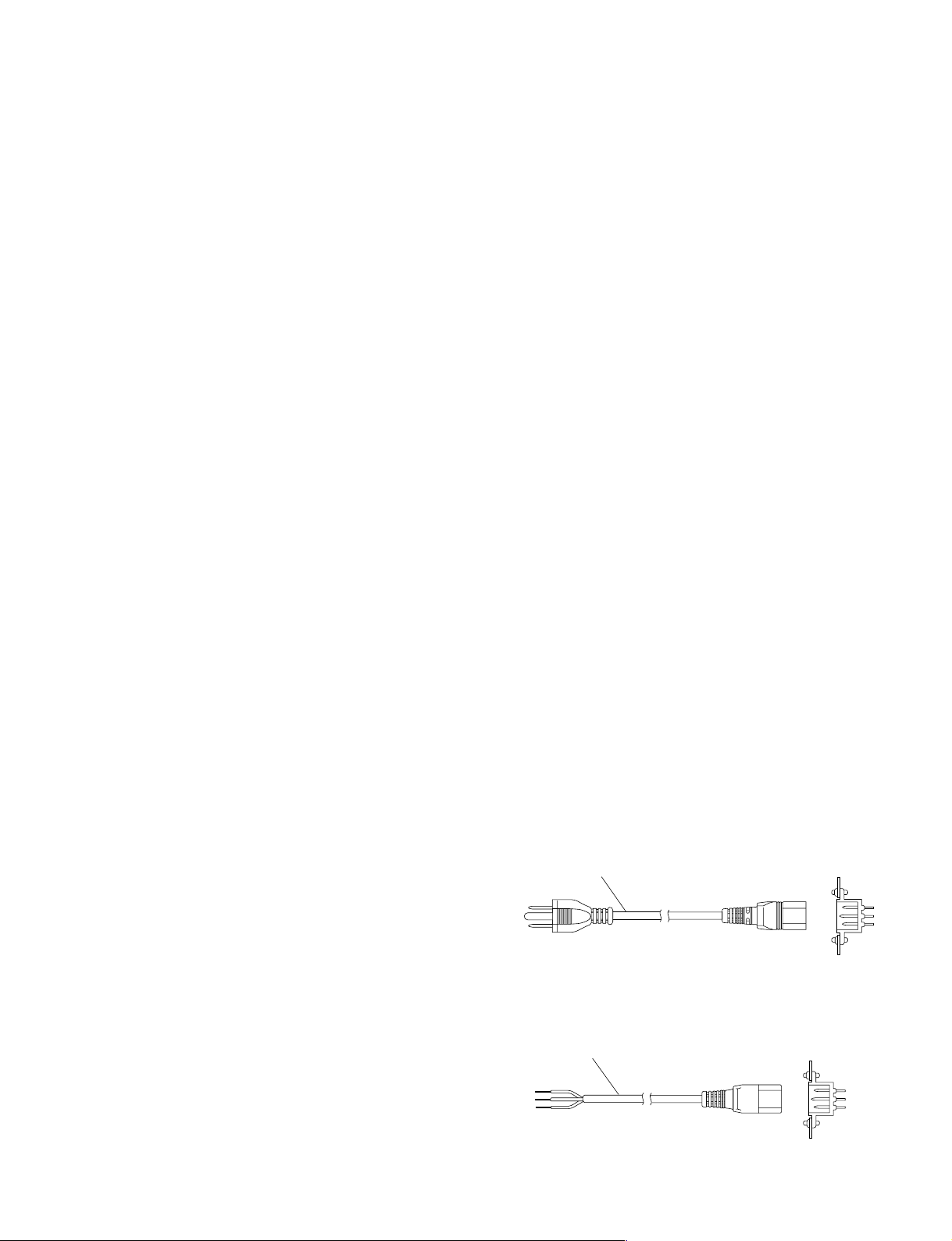
For customers in the U.S.A. and Canada
1 Power cord, 125 V 10 A (2.4 m) : ! 1-557-377-11
AC inlet
1
Installation
1-1. Operating Environment
Operating guaranteed temperature : +5 dC to +40 dC
Performance guaranteed temperature : +10 dC to +35 dC
Operating humidity : 10 % to 90 %
(relative humidity)
Storage temperature : _20 dC to +60 dC
Mass (when all options are installed) :
DVS-9000 : Approx. 43 kg
DVS-9000SF : Approx. 25 kg
Prohibited locations for installation
. Areas where the unit will be exposed do direct sunlight
or any other strong lights.
. Dusty areas
. Areas subject to vibration.
. Areas with strong electric or magnetic fields.
. Areas near heat sources.
. Areas subject to electrical noise.
. Areas subject where is subjected to static electricity.
Ventilation
The inside of the DVS-9000-C/DVS9000SF-C (DVS-9000
series hereafter) is cooled by a fan (both sides).
The power supply can be damaged if the exhaust vent
(both sides) and air intake (front panel) are blocked or the
fan is stopped.
Therefore, leave a blank space of more than 10 cm in the
front and both sides of the DVS-9000 series).
m
. As the inrush current at turn-on is a maximum 60 A (at
100 V)/110 A (at 230 V), the capacity of the AC power
source must be commensurate with this load.
If the capacity of the AC power is not adequately large,
the AC power source braker will operate or the unit will
abnormally operate.
. The DVS-9000 contains the two power supply units as
the standard configuration. A maximum of four power
supply units may be installed. When starting up the
DVS-9000, be sure to turn on the power of two or more
power supply units.
. The DVS-9000SF contains the single power supply unit
as the standard configuration. A maximum of two power
supply units may be installed. When starting up the
DVS-9000, be sure to turn on the power of one or more
power supply units.
1-2-2. Recommended Power Cord
w
. The power cord is not supplied with the DVS-9000
series.
Be sure to use the power cord that is applicable to places
in the area.
To avoid a fire or an electric shock, be sure to use the
designated power cord.
. Do not damage the power cord otherwise a fire or
electric shock may result.
1-2. Power Supply
1-2-1. Power Specifications
A switching regulator is used for the power supply of this
unit. The voltage within the range of 100 V to 240 V can
be used without changing the supply voltage.
Power requirements : AC 100 to 240 V ± 10 %
Power frequency : 50/60 Hz
Current consumption (when all options are installed) :
DVS-9000 : 8.6 to 4.2 A
DVS-9000SF : 5.5 to 2.5 A
DVS-9000/9000SF
For customers in the all European countries
1 Power cord, 250 V 10 A (2.4 m) : ! 1-782-929-21
1
AC inlet
1-1
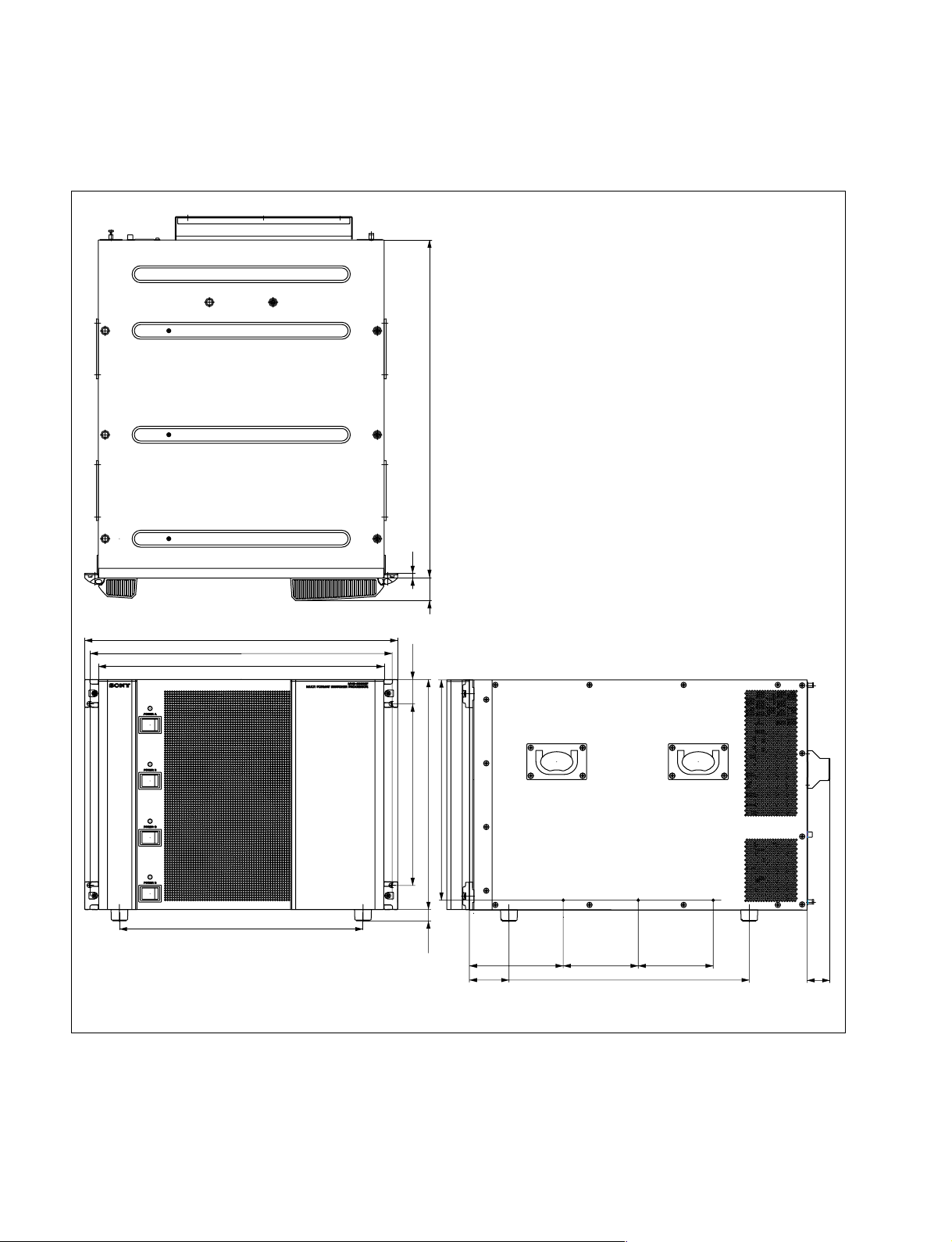
1-3. Installation Space (External dimensions)
1-3. Installation Space (External dimensions)
1-3-1. DVS-9000
520
482
465
440
375
7
35
37.6
279.4
354(8U)
17.5
339
144.5 115.5 115.5
61
370
35
1-2
Unit : mm
DVS-9000/9000SF
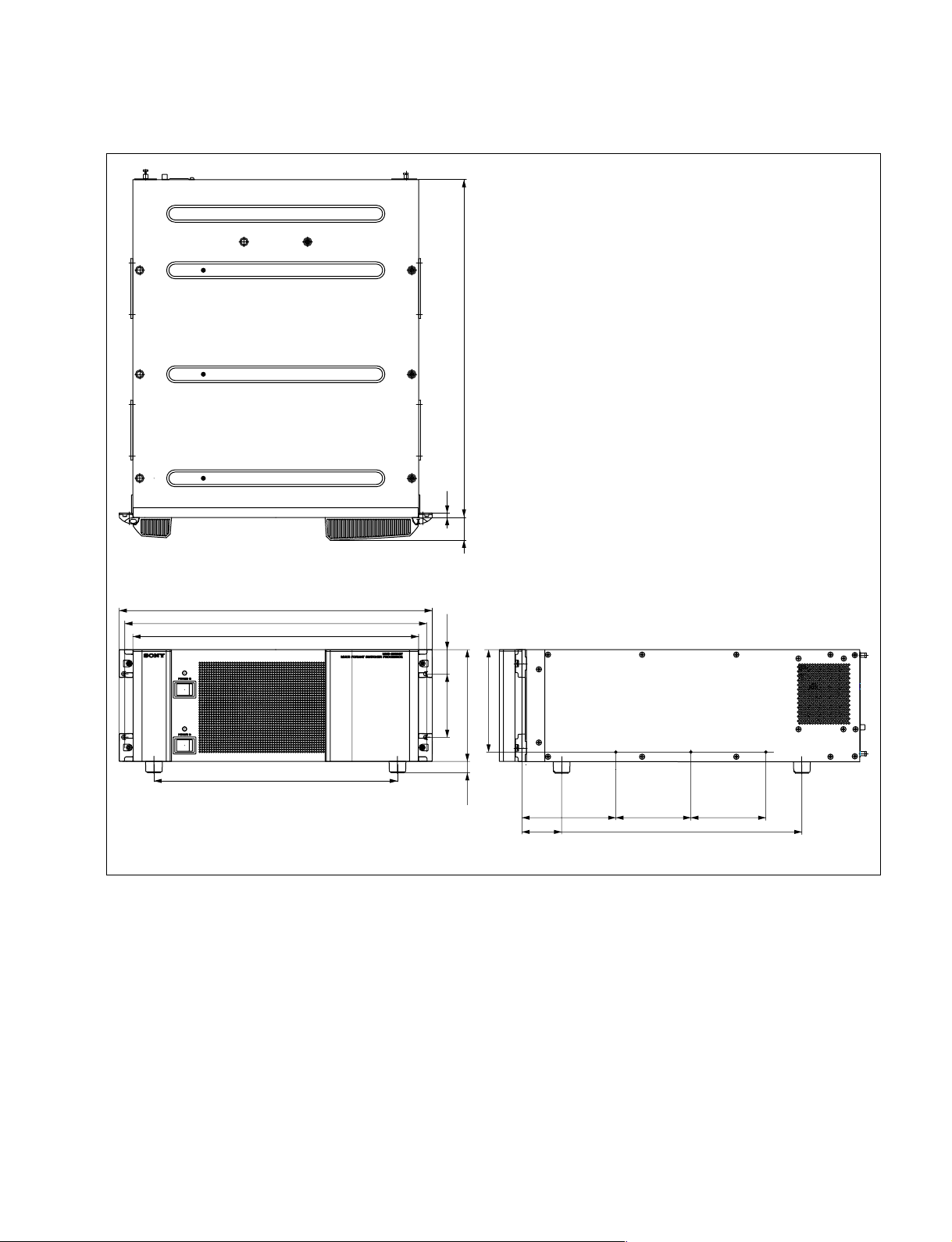
1-3-2. DVS-9000SF
1-3. Installation Space (External dimensions)
520
7
482
465
440
375
35
37.2
101.6
176(4U)
17.5
161
144.5 115.5 115.5
61
380
Unit : mm
DVS-9000/9000SF
1-3

1-4. Installing the Options
1-4. Installing the Options
The DVS-9000-C/DVS9000SF-C is shipped from the
factory with the necessary option boards (refer to the
following table) already installed in accordance with the
specified system configuration.
The following options are available for the DVS-9000/
9000SF.
DVS-9000/9000SF Option List
Model name
Plug-in board
BKDS-9160 (DVS-9000 only) OUT-26 board CNO-19 board
24 Output Board Set
BKDS-9161 (DVS-9000 only) _ CNO-20 board
8 Monitor Output Board
BKDS-9162 (DVS-9000SF only) _ CNO-19 board
12 Output Board
BKDS-9210 MIX-46 board _
Mix/Effect Board
BKDS-9470 DVP-24 board CN-2354 board
DME Board Set CA-54 board
MKS-8110SD _ CNI-10 board
17 Input Board
MKS-8111SD (DVS-9000 only) _ CNI-17 board
Additional 12 Input Board
HK-PSU04 __
Power Supply Unit
BZS-9250
Simple P/P Software
BZS-9420
Color Corrector Software
* : BZS-9250 and BZS-9420 are the software options.
*
*
__
__
Connector board
CN-2132C board
1-4-1. Installing the Plug-in Boards
Each plug-in board of the Production Switcher Processor
DVS-9000/9000SF is allocated to a specific slot into which
they must be installed. Check to see that the respective
plug-in boards are installed in their respective slots.
The name of the board is shown near the eject lever at the
left-most end of each plug-in board.
Names of the plug-in boards and the slot numbers, to
which the plug-in boards are allocated, are shown on the
Extract PWB stopper assembly inside the front panel of the
DVS-9000/9000SF. Install the respective plug-in boards
according to this instruction.
n
Check to see that connectors of the plug-in boards are
securely inserted into the mother board (DVS-9000 : MB985 board, DVS-9000SF : MB-986 board) without loose
contact.
If any plug-in board is inserted into the incorrect slot, it
causes a system error and the system will not work correctly.
c
Be sure to turn off the POWER switch before starting
installation work.
If installation work is started with the POWER switch left
on, it may cause electrical shock or damage to printed
circuit boards.
1-4
DVS-9000/9000SF
1-4. Installing the Options
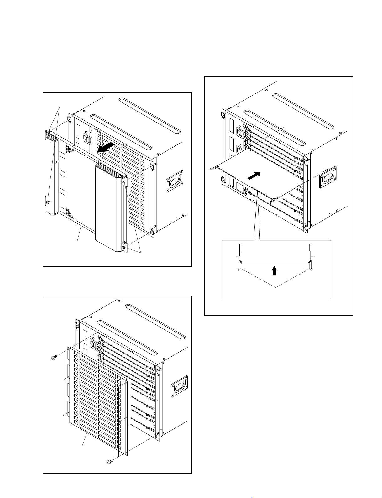
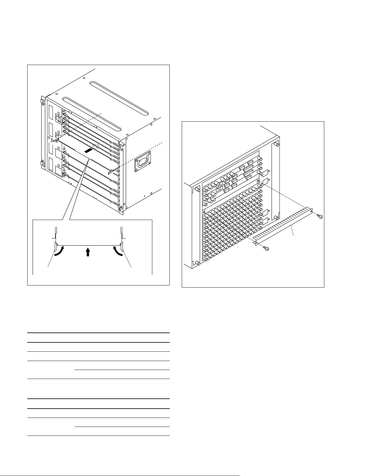
Installation Procedure
1. Turn off the main power of the DVS-9000/9000SF and
disconnect the AC power cord from the wall outlet.
2. Loosen the four screws (with drop-safe) and remove
the front panel to the arrow.
Screws
(with drop-safe)
4. While the eject levers are opened as shown in the
illustration, insert the plug-in board into the board
guide rail.
Front panel
Screws (with drop-safe)
(The illustration shows the DVS-9000.)
3. Remove the screws (DVS-9000: 6 screws, DVS-9000SF:
4 screws) and remove the Extract PWB stopper assembly.
B3 x 5
Eject levers
(The illustration shows the DVS-9000.)
Extract PWB stopper
assembly
DVS-9000/9000SF
B3 x 5
(The illustration shows
the DVS-9000.)
1-5
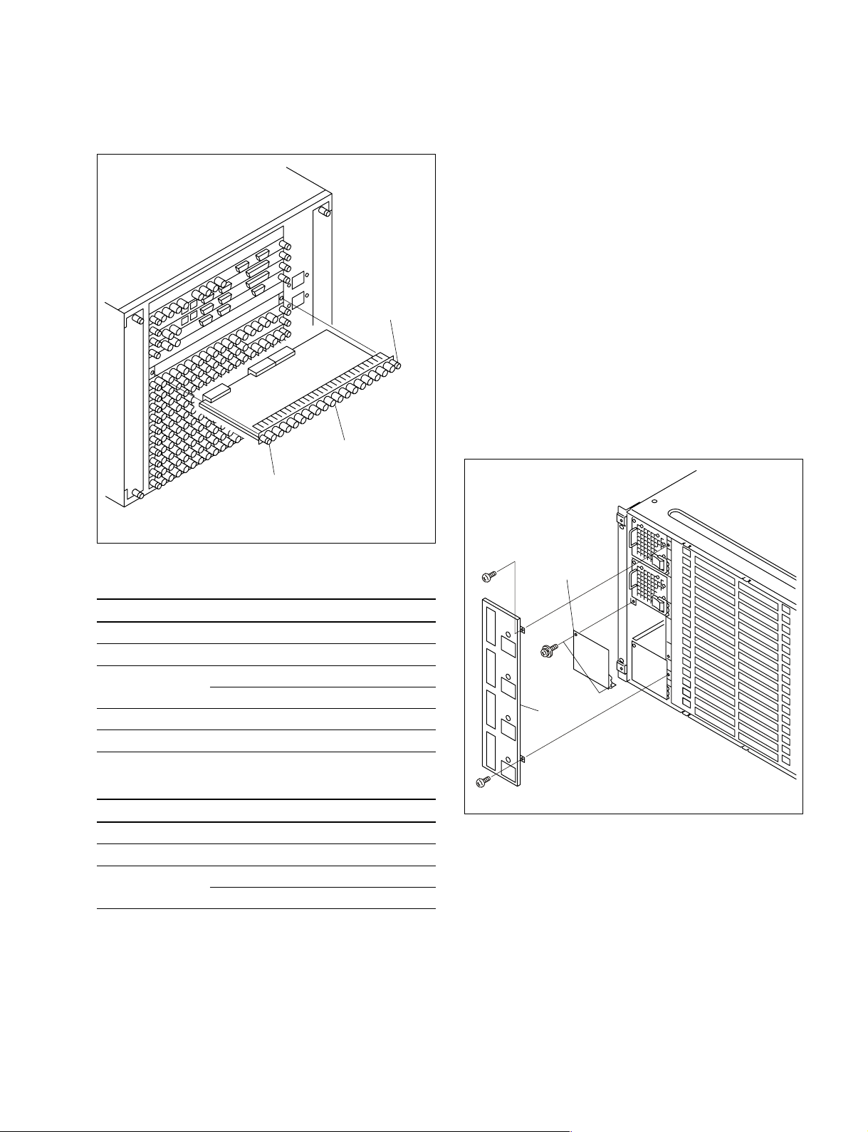
1-4. Installing the Options
5. While closing the eject levers in the direction of arrow
1, push in the plug-in board.
1-4-2. Installing the Connector Board
1. Remove the two screws and remove the blank panel.
m
. To install the connector board into the slot in which
the other board is installed already, loosen the two
fixing screws and remove the connector board that is
installed already.
. Store the removed blank panel in a safe place.
B3 x 5
1
Eject lever Eject lever
(The illustration shows the DVS-9000.)
1
6. Attach the plug-in board loose-proof assembly and the
front panel by reversing the installation steps of 2, 3.
DVS-9000 option
Name of option Name of board
BKDS-9160 OUT-26 board 16
BKDS-9210 MIX-46 board 6, 7
BKDS-9470 DVP-24 board 2
CA-54 board 3
Slot on the front side
DVS-9000SF option
Name of option Name of board
BKDS-9210 MIX-46 board 6
BKDS-9470 DVP-24 board 1
CA-54 board 2
Slot on the front side
Blank panel
B3 x 5
(The illustration shows the DVS-9000.)
1-6
DVS-9000/9000SF
1-4. Installing the Options
2. Insert the connector board horizontally level and
secure it with the two fixing screws.
Screws
(with drop-safe)
Connector board
Screws
(with drop-safe)
(The illustration shows the DVS-9000.)
1-4-3. Installing the HK-PSU04
The HK-PSU04 is used after it is installed in the DVS9000/9000SF.
n
Before installing the HK-PSU04, be sure to turn off the
main power. If the HK-PSU04 is installed while the main
power is turned on, it can result in electrical shock or
damage to printed circuit boards.
Installation procedure
1. Remove the front panel of the DVS-9000/9000SF.
(Refer to Section 1-4-1.)
2. Remove the two screws (B3 x 5) fixing the PS cover,
and remove the PS cover.
3. Remove the two screws (PSW3 x 6) fixing the blank
panel to the location where the HK-PSU04 is going to
be installed. Then remove the blank panel.
DVS-9000 option
Name of option Name of board
BKDS-9160 CNO-19 board 16, 17
BKDS-9161 CNO-20 board 8
BKDS-9470 CN-2354 board 2
CN-2132C board 3
MKS-8110SD CNI-10 board 11, 12, 13
MKS-8111SD CNI-17 board 9
Slot on the rear side
DVS-9000SF option
Name of option Name of board
MKS-8110SD CNI-10 board 8
BKDS-9162 CNO-19 board 6
BKDS-9470 CN-2354 board 1
CN-2132C board 2
Slot on the rear side
Blank panel
B3 x 5
PSW
3 x 6
PS cover
B3 x 5
(The illustration shows the DVS-9000.)
n
Store the removed blank panel in a safe place.
DVS-9000/9000SF
1-7
 Loading...