

Page 1

INSTRUCTION MANUAL
Sonics & Materials, Inc.
Models
1595 Press /
1596 Actuator
Page 2

W A R N I N G
Go To Top Of Document
SAFETY PRECAUTIONS
READ BEFORE INSTALLING OR USING THE EQUIPMENT
This system has been designed to assure maximum operator safety.
However, no design can completely protect against improper usage. For
maximum safety and equipment protection, observe the following warnings at
all times and read the instruction manual carefully before you attempt to
operate the equipment.
– The equipment has safety devices that require both hands to be on the
palm buttons until the horn contacts the work piece. Do not defeat or
modify these safety devices.
– Do not use with foot switch unless alternate means of pinch-point
protection is provided.
– High voltage is present in the equipment. Disconnect plug before removing
cover or servicing.
– Make sure equipment is properly grounded with a 3-prong plug. Before
plugging in equipment, test outlet for proper earth grounding.
– High voltage potential may be present in the converter as a result of
temperature changes. Do not touch the converter contact unless you first
short both pins or the button to the converter case with an insulated tool.
– Never squeeze or grab a vibrating horn.
– Do not modify horn configurations.
– Ultrasonic welders operate above normal audibility for most people. Ear
protection is recommended.
– Do not affix any device to any portion of the horn.
Sonics & Materials, Inc.
Corporate Headquarters European Office
53 Church Hill Road • Newtown, CT 06470 USA 13, Rue Pre-de-la-Fontaine • CH - 1217 Meryin/Satigny, Switzerland
203.270.4600 • 800.745.1105 • 203.270.4610 fax (41) (0) 22/364 1520 • (41) (0) 22/364 2161 fax
www.sonics.biz • [email protected] [email protected]
Information contained in this manual is subject to change without notice. Sonics & Materials, Inc. is not responsible for any typographic errors.
© Sonics & Materials, Inc. 2007 Printed in U.S.A. Part No. 381-0036
Rev 5/07
• • • • • • • • • • • • • • • • • • • • • • • • • • • • • • • • • • • • • • • • • • • • • • • • • • • • • • • • • • • • • • • • • • • • • • • • • • • • • • • • • • • • • • • • • • • • • • • • • • • • • • • • • • • •
I NS T R U C T I O N M A N U A L • M O D E L 1 5 9 5 / 1 5 9 6
1
Page 3

• • • • • • • • • • • • • • • • • • • • • • • • • • • • • • • • • • • • • • • • • • • • • • • • • • • • • • • • • • • • • • • • • • • • • • • • • • • • • • • • • • • • • • • • • • • • • • • • • • • • • • • • • • • •
Go To Top Of Document
2
I N S T R U C T I O N M A N U A L • M O D E L 1 5 9 5 / 1 5 9 6
Page 4

T A B L E O F C O N T E N T S
Go To Top Of Document
IMPORTANT SERVICE LITERATURE . . . . . . . . . . . . . . . . . . . . . . . . . . . .4
Manual Change Information . . . . . . . . . . . . . . . . . . . . . . . . . . . . . .4
UNPACKING AND INSPECTION . . . . . . . . . . . . . . . . . . . . . . . . . . . . . . . .5
Visible Loss or Damage . . . . . . . . . . . . . . . . . . . . . . . . . . . . . . . . .5
Concealed Loss or Damage . . . . . . . . . . . . . . . . . . . . . . . . . . . . . .5
INTRODUCTION . . . . . . . . . . . . . . . . . . . . . . . . . . . . . . . . . . . . . . . . . . . . .6
OVERVIEW OF ULTRASONIC PLASTICS ASSEMBLY . . . . . . . . . . . . . .6
What is Ultrasonics? . . . . . . . . . . . . . . . . . . . . . . . . . . . . . . . . . . . .6
Principal of Ultrasonic Assembly . . . . . . . . . . . . . . . . . . . . . . . . . . .6
Ultrasonic Assembly Systems . . . . . . . . . . . . . . . . . . . . . . . . . . . . .6
GLOSSARY OF ULTRASONIC TERMS . . . . . . . . . . . . . . . . . . . . . . . . . . .8
INSTALLATION . . . . . . . . . . . . . . . . . . . . . . . . . . . . . . . . . . . . . . . . . . . . . .9
Electrical Power . . . . . . . . . . . . . . . . . . . . . . . . . . . . . . . . . . . . . . .9
Air Supply . . . . . . . . . . . . . . . . . . . . . . . . . . . . . . . . . . . . . . . . . . . .9
Setting Up . . . . . . . . . . . . . . . . . . . . . . . . . . . . . . . . . . . . . . . . . . . .9
Key Components . . . . . . . . . . . . . . . . . . . . . . . . . . . . . . . . . . . . . . .9
Connections . . . . . . . . . . . . . . . . . . . . . . . . . . . . . . . . . . . . . . . . .10
Options . . . . . . . . . . . . . . . . . . . . . . . . . . . . . . . . . . . . . . . . . . . . .10
OPERATING PROCEDURES . . . . . . . . . . . . . . . . . . . . . . . . . . . . . . . . . .11
Control Panel . . . . . . . . . . . . . . . . . . . . . . . . . . . . . . . . . . . . . . . . .11
INITIAL EQUIPMENT SETUP . . . . . . . . . . . . . . . . . . . . . . . . . . . . . . . . . .12
Assembling and Mounting Converter, Booster and Horn . . . . . . .12
Horn and Fixture Alignment . . . . . . . . . . . . . . . . . . . . . . . . . . . . .14
Positive Stop Adjustment . . . . . . . . . . . . . . . . . . . . . . . . . . . . . . . .15
OPERATION . . . . . . . . . . . . . . . . . . . . . . . . . . . . . . . . . . . . . . . . . . . . . . .16
Actuation . . . . . . . . . . . . . . . . . . . . . . . . . . . . . . . . . . . . . . . . . . . .16
Emergency Stop . . . . . . . . . . . . . . . . . . . . . . . . . . . . . . . . . . . . . .16
FINE ADJUSTMENTS . . . . . . . . . . . . . . . . . . . . . . . . . . . . . . . . . . . . . . . .17
Pressure Switch Adjustment . . . . . . . . . . . . . . . . . . . . . . . . . . . . .17
Upper Limit Switch . . . . . . . . . . . . . . . . . . . . . . . . . . . . . . . . . . . .18
Booster Selection . . . . . . . . . . . . . . . . . . . . . . . . . . . . . . . . . . . . .18
Pressure . . . . . . . . . . . . . . . . . . . . . . . . . . . . . . . . . . . . . . . . . . . .19
Re-Establishing Proper Booster/Horn Interfaces . . . . . . . . . . . . .19
MAINTENANCE . . . . . . . . . . . . . . . . . . . . . . . . . . . . . . . . . . . . . . . . . . . . .21
Repairs / Service . . . . . . . . . . . . . . . . . . . . . . . . . . . . . . . . . . . . . .21
WARRANTY . . . . . . . . . . . . . . . . . . . . . . . . . . . . . . . . . . . . . . . . . . . . . . . .22
Limitation of Warranty . . . . . . . . . . . . . . . . . . . . . . . . . . . . . . . . . .22
• • • • • • • • • • • • • • • • • • • • • • • • • • • • • • • • • • • • • • • • • • • • • • • • • • • • • • • • • • • • • • • • • • • • • • • • • • • • • • • • • • • • • • • • • • • • • • • • • • • • • • • • • • • •
I N S T R U C T I O N M A N U A L • M O D E L 1 5 9 5 / 1 5 9 6
3
Page 5

I M P O R T A N T S E R V I C E L I T E R A T U R E
Go To Top Of Document
The system supplied with this instruction manual is constructed of the finest
material and the workmanship meets the highest manufacturing standards. It
has been thoroughly tested and inspected before leaving the factory and
when used in accordance with the procedures outlined in this manual, will
provide you with many years of safe and dependable service.
NOTE: Please read
carefully before
operating the
equipment, then
forward to your service
department.
MANUAL CHANGE INFORMATION
We continually strive to be at the forefront of the latest electronic
developments by adding circuit and component improvements to our
equipment as soon as they are developed and tested.
Sometimes, due to printing and shipping requirements, we cannot incorporate
these changes immediately into printed manuals. Hence, your manual may
contain new change information. Change information, if any, is located in the
Appendix.
We reserve the right to make any changes in the design or construction of our
equipment at any time, without incurring any obligation to make any change
whatsoever in units previously delivered.
The technical data and schematics in the manual are for informational
purposes only and may not reflect the current configuration being shipped
from our factory. Upon formal request, complete and up-to-date information
can be provided from the factory free of charge.
• • • • • • • • • • • • • • • • • • • • • • • • • • • • • • • • • • • • • • • • • • • • • • • • • • • • • • • • • • • • • • • • • • • • • • • • • • • • • • • • • • • • • • • • • • • • • • • • • • • • • • • • • • • •
4
I N S T R U C T I O N M A N U A L • M O D E L 1 5 9 5 / 1 5 9 6
Page 6

U N P A C K I N G A N D I N S P E C T I O N
Go To Top Of Document
Before unpacking the equipment, check the shipping carton for any visible
damage. If you see any, be sure to follow the procedures described below
under “Visible Loss or Damage.” Otherwise, proceed to remove the equipment
from the carton. Before disposing of any packing material, check it carefully
for small parts. Then perform a visual inspection of the equipment to detect
NOTE: We recommend
keeping all carton(s)
and packing material in
case it might be
necessary to move the
equipment, or to ship it
for repair.
any evidence of damage which might have occurred during shipment. Check
the following:
1. all components against the enclosed packing list,
2. all module plug-in units,
3. all wire plug-in connections.
The equipment was carefully packed and thoroughly inspected before leaving
our factory. All units are tested and checked for problems prior to shipping. It
is asked that when a problem does occur that all parts and components be
inspected for damage (especially when the unit is not in working order when
received). Responsibility for safe delivery was assumed by the carrier upon
acceptance of the shipment. Claims for loss of damage sustained in transit
must therefore be made upon the carrier, as follows:
VISIBLE LOSS OR DAMAGE
Any external evidence of loss or damage must be noted on the freight bill or
express receipt, and signed by the carrier’s agent. Failure to adequately
describe such external evidence of loss or damage may result in the carrier’s
refusal to honor a damage claim. The form required to file such a claim will
be supplied by the carrier.
CONCEALED LOSS OR DAMAGE
Concealed loss or damage means loss or damage which does not become
apparent until the merchandise has been unpacked. The contents might have
been damaged in transit due to rough handling even though the container
may not show external damage. When the damage is discovered upon
unpacking, make a written request for inspection by the carrier’s agent within
48 hours of the delivery date. Then file a claim with the carrier since such
damage is the carrier’s responsibility. The form required to file such a claim
will be supplied by the carrier. Do not destroy packing materials, or move
material from one location to another before the carrier makes their
inspection.
If the system or any unit is damaged, notify “Sonics.” “Sonics” will arrange for
repair or replacement of damaged equipment without waiting for the claim
against the carrier to be settled, provided a new purchase order is issued to
cover the repair or replacement costs. Should any damage, shortage or
discrepancy exist, please notify us immediately.
• • • • • • • • • • • • • • • • • • • • • • • • • • • • • • • • • • • • • • • • • • • • • • • • • • • • • • • • • • • • • • • • • • • • • • • • • • • • • • • • • • • • • • • • • • • • • • • • • • • • • • • • • • • •
I N S T R U C T I O N M A N U A L • M O D E L 1 5 9 5 / 1 5 9 6
5
Page 7

I N T R O D U C T I O N
Go To Top Of Document
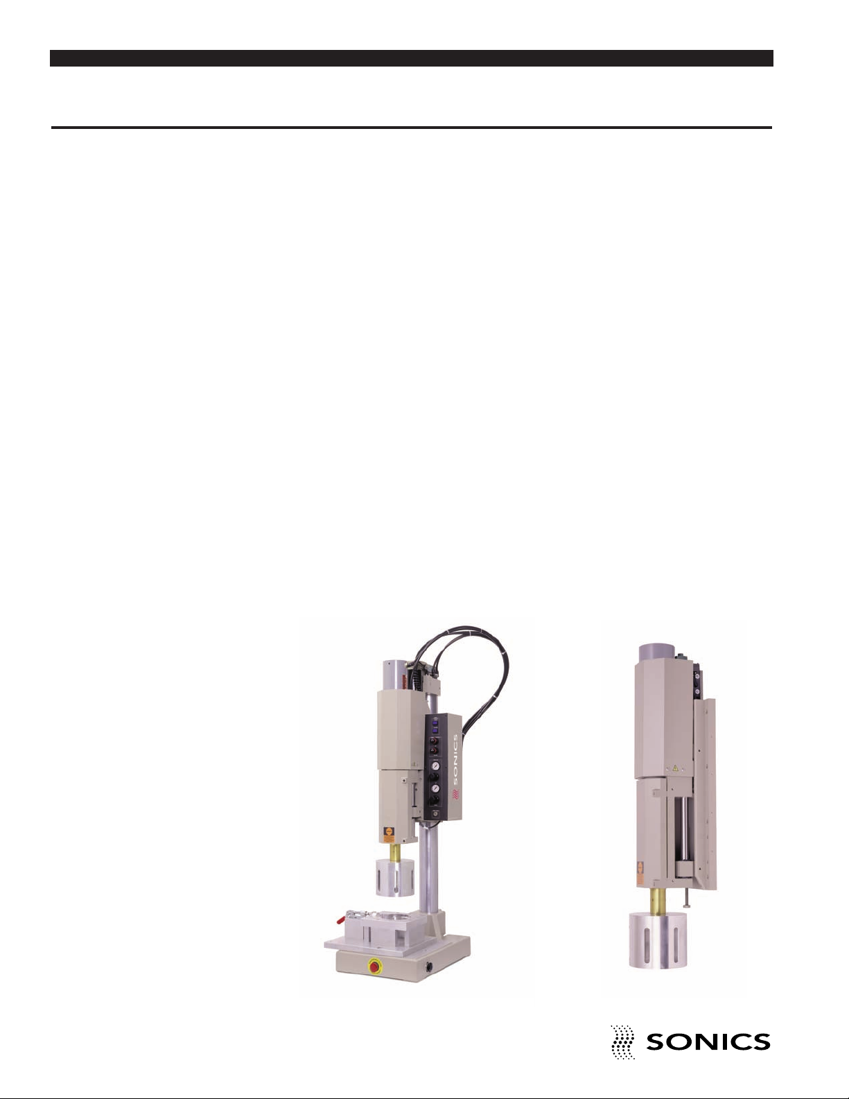
The models 1595 and 1596 are 15 kHz pneumatic actuators used for
ultrasonic plastics assembly. The 1595 is a tabletop version, whereas the
1596 can be mounted on a bridge or rigid structural member for use with
automated systems. Both models can be supplied with the following GXSeries power supplies:
■ GXT . . . . . . .Weld by digital time
■ GXE . . . . . .Weld by digital time and/or constant energy
■ GXL . . . . . . .Weld by digital time, constant energy and/or distance*
*Requires optional linear encoder.
Both actuators are also compatible with E-Series power supplies.
O V E R V I E W O F U L T R A S O N I C P L A S T I C S A S S E M B L Y
WHAT IS ULTRASONICS?
Ultrasonics refers to vibrational waves with a frequency above the human
audible range which is usually above 18,000 cycles per second (Hz).
PRINCIPLE OF ULTRASONIC ASSEMBLY
The basic principle of ultrasonic assembly involves conversion of high
frequency electrical energy to high frequency mechanical energy in the form
of reciprocating vertical motion which, when applied to a thermoplastic,
generates frictional heat at the plastic/plastic or plastic/metal interface. In
ultrasonic welding, this frictional heat melts the plastic, allowing the two
surfaces to fuse together; in ultrasonic staking or insertion, the controlled flow
of molten plastic is used to capture or lock another material in place (staking)
or encapsulate a metal insert (insertion).
ULTRASONIC ASSEMBLY SYSTEMS
“Sonics” ultrasonic assembly systems are generally composed of the
following major elements: a power supply, converter, booster, horn, pneumatic
press and holding fixture, as detailed in the diagram on the next page. A
review of this diagram will help you understand the basic elements involved in
the assembly process and their relation to each other.
• • • • • • • • • • • • • • • • • • • • • • • • • • • • • • • • • • • • • • • • • • • • • • • • • • • • • • • • • • • • • • • • • • • • • • • • • • • • • • • • • • • • • • • • • • • • • • • • • • • • • • • • • • • •
6
I N S T R U C T I O N M A N U A L • M O D E L 1 5 9 5 / 1 5 9 6
Page 8
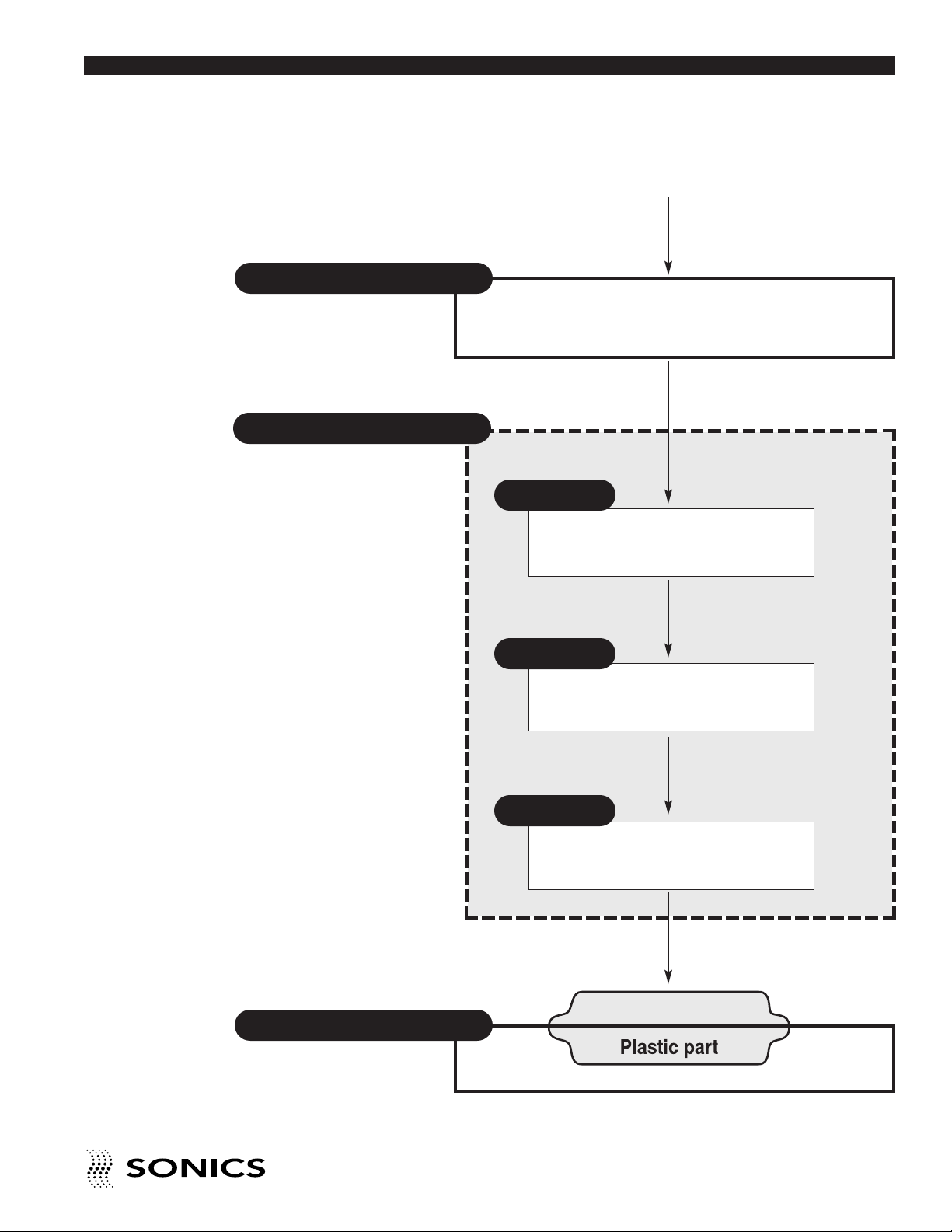
“SONICS” ULTRASONIC ASSEMBLY SYSTEMS
Go To Top Of Document
Power Supply/Generator
Actuator/Press
Provides compressive force
and mounting for Converter,
Booster, Horn assembly
50/60Hz
Electrical power
Generates ultrasonic electrical energy
(15/20/40 kHz)
Ultrasonic
electrical energy
Converter
Transforms ultrasonic electrical energy
to ultrasonic mechanical vibrations
Ultrasonic Vibrations
Holding Fixture
Aligns and supports part
Booster
Increases or decreases amplitude
Ultrasonic Vibrations
Horn
Contacts and transfers vibrational
energy to plastic part
Ultrasonic Vibrations
• • • • • • • • • • • • • • • • • • • • • • • • • • • • • • • • • • • • • • • • • • • • • • • • • • • • • • • • • • • • • • • • • • • • • • • • • • • • • • • • • • • • • • • • • • • • • • • • • • • • • • • • • • • •
I N S T R U C T I O N M A N U A L • M O D E L 1 5 9 5 / 1 5 9 6
7
Page 9
G L O S S A R Y O F U L T R A S O N I C T E R M S
Go To Top Of Document
POWER SUPPLY/GENERATOR – The solid state power supply converts
standard 50/60 Hz electrical power to 15,000 Hz, 20,000 Hz, and 40,000 Hz
(15/20/40 kHz) electrical energy.
ACTUATOR/PRESS – The pneumatic actuator provides compressive force
and mounting for the converter, booster, and horn assembly. The tabletop
press consists of a base assembly, column and actuator (head).
CONVERTER – The converter changes the high frequency electrical energy
supplied by the power supply to high frequency mechanical vibrations.
BOOSTER – Successful ultrasonic welding often depends on having the right
amplitude at the horn face. Often it is not possible to design a horn which has
both the necessary shape and required gain (ratios of input amplitude to
output amplitude). In such cases, a booster is placed between the converter
and the horn to either increase or decrease the amplitude of the horn. In
addition to changing/maintaining the amplitude, the booster provides support
and alignment in the welding system. (See page 18 for booster selection.)
HORN – The horn is a tuned component of the system which comes in
contact with the parts to be assembled. The horn 1) transfers the ultrasonic
vibrations produced from the converter to the parts being welded, and 2)
applies necessary force to the assembly while the material resolidifies.
HOLDING FIXTURE – The holding fixture or nest assures proper alignment
and support of the parts being assembled.
1595 1596
• • • • • • • • • • • • • • • • • • • • • • • • • • • • • • • • • • • • • • • • • • • • • • • • • • • • • • • • • • • • • • • • • • • • • • • • • • • • • • • • • • • • • • • • • • • • • • • • • • • • • • • • • • • •
8
I N S T R U C T I O N M A N U A L • M O D E L 1 5 9 5 / 1 5 9 6
Page 10
I N S T A L L A T I O N
Go To Top Of Document
ELECTRICAL POWER
The press is powered by the power supply. Consult your power supply
instruction manual to determine power specifications.
AIR SUPPLY
The press requires a source of dry, filtered (5 micron), oil-free, compressed
air capable of supplying a constant line pressure of 100 psig. (690 kPa / 7 bar)
at a minimum capacity of 4 CFM (.1 cubic meters).
Do not connect the press
to an air source supplied
by a compressor lubricated
with synthetic oils or oils
containing phosphate
esters or chlorinated
hydrocarbons. This type of
lubricant may cause the air
filter to malfunction, and
the plastic bowl to rupture.
NOTE: If the power supply
is to be run continuously,
air cooling of the converter
and horn is required. Use
clean, dry compressed air
filtered down to 5 microns
(supplied to converter
fitting).
SETTING UP
The press should be installed in a clear, uncluttered location that is free from
excessive dirt, dust, corrosive fumes, and temperature and humidity
extremes. The selected installation site should be near the electrical power
and air supply sources and away from any equipment that generates
abnormally high electrical transients. Observe the following additional
instructions when installing the press:
a. The press should be placed on a sturdy, level table or bench capable of
supporting a minimum of 500 pounds (227 kg).
b. Allow at least 6 inches (152.4mm) at the rear of the press for cable
connections.
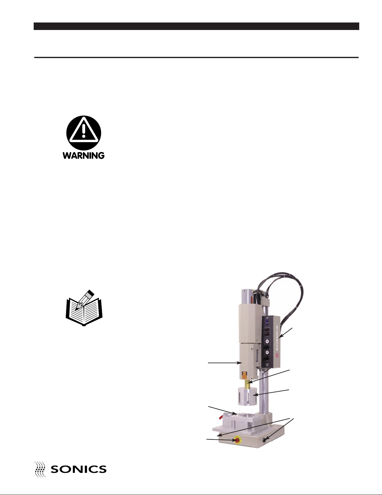
KEY COMPONENTS
PNEUMATIC
CONTROL PANEL
CONVERTER
HOUSING DOOR
HOLDING FIXTURE
BOOSTER
HORN
PALM ACTIVATION
BUTTONS
EMERGENCY STOP
BUTTON
• • • • • • • • • • • • • • • • • • • • • • • • • • • • • • • • • • • • • • • • • • • • • • • • • • • • • • • • • • • • • • • • • • • • • • • • • • • • • • • • • • • • • • • • • • • • • • • • • • • • • • • • • • • •
I N S T R U C T I O N M A N U A L • M O D E L 1 5 9 5 / 1 5 9 6
9
Page 11
NOTE: Do not strain or
Go To Top Of Document
kink the cables. When
going around corners,
allow as wide a bend as
possible. Do not run the
cables parallel to any
power line within a
distance of less than 1
foot (304.8mm).
CONNECTIONS
When making the initial connections, make sure all power is disconnected.
1. Connect the air supply source to the press air filter located at the bottom
rear of the control panel, using a hose having a minimum inside diameter
of 1/4 inch (6.4 mm).
2. Connect the RF and base (actuating) cables of the (table top only) press to
the power supply. (Consult your power supply instruction manual for
details.)
3. Check with your electrician if you have any wiring questions.
OPTIONS
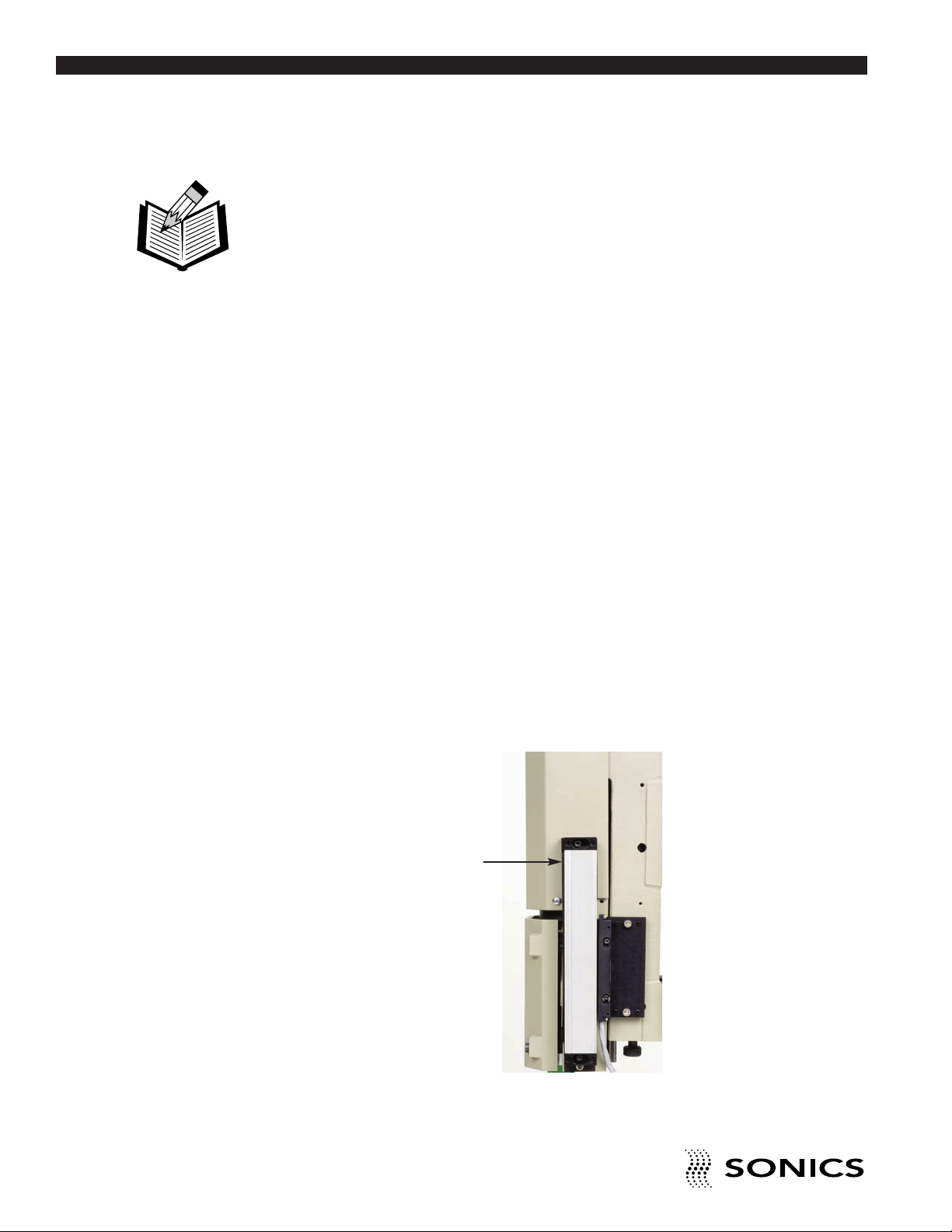
A Linear Encoder is available as an option for the 1595 and 1596 models.The
Linear Encoder allows distance-controlled welding in both incremental and
absolute modes.
The Linear Encoder is supplied with a 9-pin male connector that connects to
a matching 9-pin female connector on the power supply (factory installed).
LINEAR ENCODER
• • • • • • • • • • • • • • • • • • • • • • • • • • • • • • • • • • • • • • • • • • • • • • • • • • • • • • • • • • • • • • • • • • • • • • • • • • • • • • • • • • • • • • • • • • • • • • • • • • • • • • • • • • • •
10
I N S T R U C T I O N M A N U A L • M O D E L 1 5 9 5 / 1 5 9 6
Page 12
O P E R A T I N G P R O C E D U R E S
Go To Top Of Document
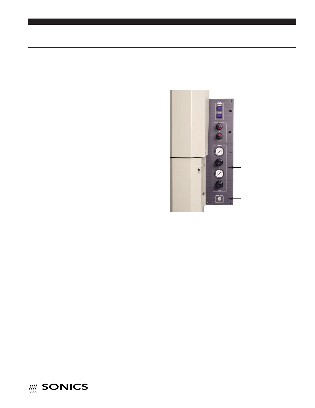
CONTROL PANEL
Located to the right of the converter housing is a control panel with the
following features:
❶
❷
❸
❹
1. Blue HEAD POSITION buttons (labeled “RAISE” and “LOWER”) which
move the head up or down on the column when depressed.
2. Black and red SPEED CONTROL knobs which allow regulation of the
speed at which the horn descends and returns (stroke speed).
These controls are factory adjusted for average operating conditions. When
minor adjustments are necessary, be sure to adjust in small degrees.
The upper knob, labeled “UP,” controls the return speed – turn it clockwise
to slow the speed, counterclockwise to increase speed.
The lower knob, labeled “DOWN,” controls the extend speed – turn it
clockwise to slow the speed, counterclockwise to increase the speed.
3. Black PRESSURE REGULATORS with corresponding gauges that
allow regulation of the pressure with which the horn contacts the part and
returns to the home position. Pull the knobs to make adjustments, and then
push in to lock settings when desired pressure is displayed. Once pulled,
turning the knobs clockwise increases pressure, and turning them
counterclockwise decreases pressure.
4. The HORN DOWN key switch which when turned clockwise moves the
converter housing to the extended position (this action does not cause
ultrasonics to be activated).
• • • • • • • • • • • • • • • • • • • • • • • • • • • • • • • • • • • • • • • • • • • • • • • • • • • • • • • • • • • • • • • • • • • • • • • • • • • • • • • • • • • • • • • • • • • • • • • • • • • • • • • • • • • •
I N S T R U C T I O N M A N U A L • M O D E L 1 5 9 5 / 1 5 9 6
11
Page 13

I N I T I A L E Q U I P M E N T S E T U P
Go To Top Of Document
ASSEMBLING AND MOUNTING CONVERTER, BOOSTER,
AND HORN
If the converter, booster, and horn are not already assembled, follow these
instructions:
1. Clean the mating surfaces of the converter and booster, as well as the
Never tighten the horn to
the booster using the
housing door as the upper
wrench as this may cause
damage to the booster
and/or converter.
threaded stud and hole. Check that the stud is tight (see recommended
torque requirements on page 13).
2. Hand assemble the converter and booster together. Using spanner
wrenches as shown below, tighten to 50-55 foot-lbs. (68-75 newtonmeters). Do not force or overtighten.
CONVERTER/BOOSTER
3. Clean the mating surfaces of the booster and horn, as well as the threaded
stud and hole. Check that the stud is tight. (See recommended torque
requirements on next page.)
4. Hand assemble the horn to the booster. Using spanner wrenches as shown
below, tighten to 50-55 foot-lbs. (68-75 newton-meters). Do not
overtighten.
CONVERTER/BOOSTER/HORN
• • • • • • • • • • • • • • • • • • • • • • • • • • • • • • • • • • • • • • • • • • • • • • • • • • • • • • • • • • • • • • • • • • • • • • • • • • • • • • • • • • • • • • • • • • • • • • • • • • • • • • • • • • • •
12
I N S T R U C T I O N M A N U A L • M O D E L 1 5 9 5 / 1 5 9 6
Page 14
NOTE: When performing
Go To Top Of Document
any of the operations
described on this page and
pages 14 and 15, DO NOT
turn on the power supply.
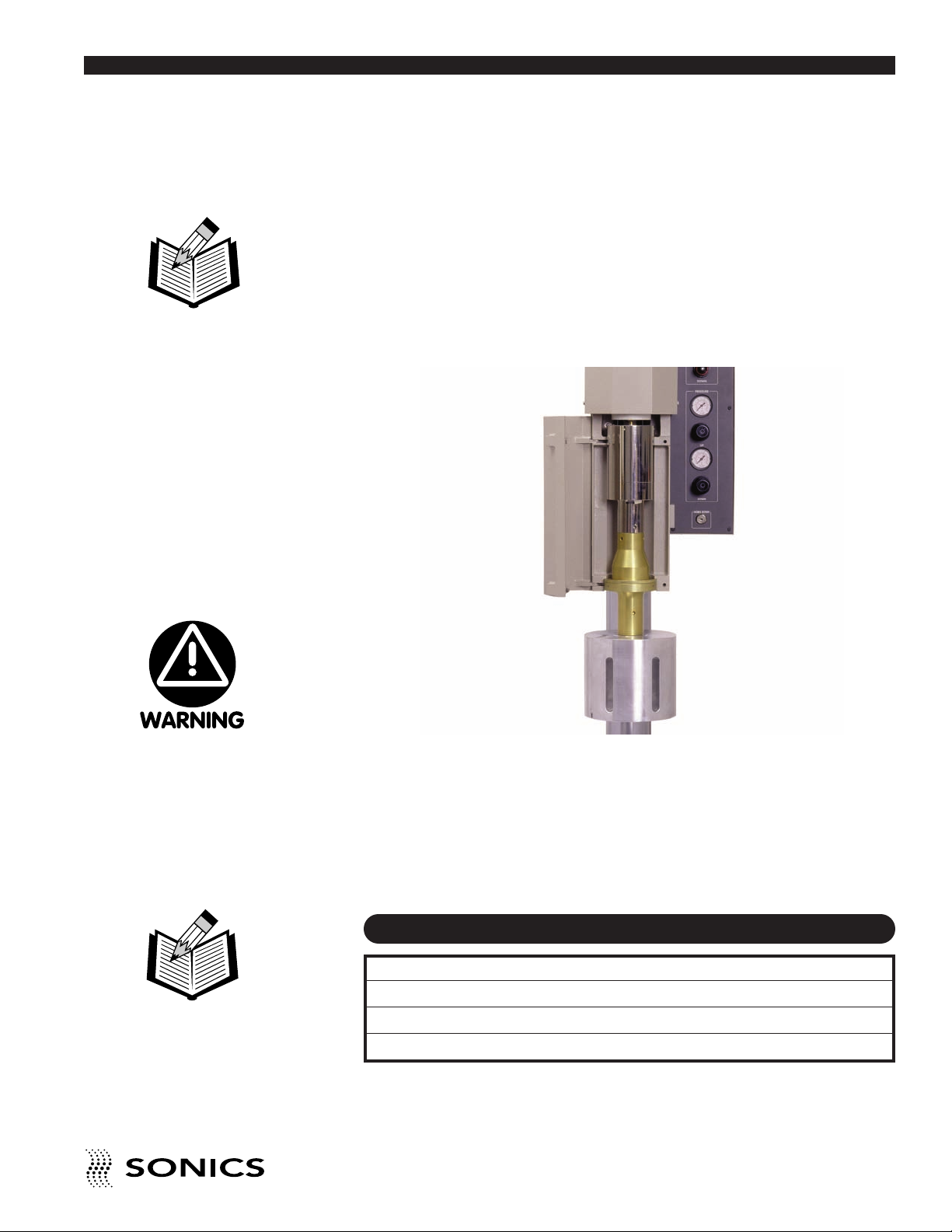
5. Using the 3/16” (4.7 mm) T-handle wrench provided, loosen (turn
counterclockwise) the two cap screws screws on the hinged converter
housing and open the door.
6. Place the converter / booster / horn assembly in the housing with the horn
facing down. Fit the male brass button connector on the top of converter
into the brass grooved ridge connector in the bottom of the interior housing,
and gently push the assembly up and in so that the booster mounting ring
rests on the lower support ridge.
CONVERTER / BOOSTER /
HORN ASSEMBLY
Never tighten the horn to
the booster using the
housing door as the upper
wrench as this may cause
damage to the booster
and/or converter.
NOTE: If you do not close
the housing door once the
assembly is in place, the
assembly can fall out.
• • • • • • • • • • • • • • • • • • • • • • • • • • • • • • • • • • • • • • • • • • • • • • • • • • • • • • • • • • • • • • • • • • • • • • • • • • • • • • • • • • • • • • • • • • • • • • • • • • • • • • • • • • • •
7. Close the converter housing door and tighten (turn clockwise) the two
socket head cap screws just until they are snug. Do not tighten the horn to
the booster using the door as the upper wrench. Hand-forcing the horn on
and off in this manner can twist the converter wires and cause a failure. If
the horn is not in the correct position to make contact with your material,
loosen the cap screws re-open the converter housing door, and re-position
the converter / booster / horn assembly.
RECOMMENDED TORQUE REQUIREMENTS
Component Foot-Lbs. Newton-Meters
Converter / Booster 50 - 55 68-75
Booster / Horn 50 - 55 68-75
Stud 55 75
I N S T R U C T I O N M A N U A L • M O D E L 1 5 9 5 / 1 5 9 6
13
Page 15

HORN AND FIXTURE ALIGNMENT
Go To Top Of Document
For maximum productivity, the clearance between the horn and the part
should be at a minimum. However, adequate clearance should be provided to
enable easy loading and unloading of the part from the holding fixture. The
maximum stroke distance is 4" (optional 6" stroke available). Ensure that the
head is not too close to the limit of its down travel distance. Otherwise, the
horn may not have sufficient distance to travel downwards to achieve a full
depth of weld. Set welding height as described below:
HEAD
ASSEMBLY
When the air pressure
is decreased, the
converter housing can
drop down to its limit,
so be sure to either
support it or remove
anything in its path.
COLUMN CLAMPS
1. Position the holding fixture loosely on the base plate using 3/8-16 screws.
2. Place the part to be welded in the fixture.
3. Set the air pressure to zero by turning the UP PRESSURE regulator knob
fully counterclockwise.
4. To get the head into the position desired, use one or both of the methods
described below to make adjustments as needed:
a. Loosen the two column clamps (counterclockwise) and use the HEAD
POSITION buttons to move the head up or down.The head can also be
manually rotated slightly (from side to side).Once the head is in the
desired position, tighten the column clamps.
b. With the column clamps locked (tightened) in place, the HORN DOWN
Key switch (which activates the air cylinder) can be used to advance the
horn.
5. Loosen the cap screws on the converter housing door and gently rotate the
converter/booster/horn assembly as required to ensure proper horn-to-part
alignment.
• • • • • • • • • • • • • • • • • • • • • • • • • • • • • • • • • • • • • • • • • • • • • • • • • • • • • • • • • • • • • • • • • • • • • • • • • • • • • • • • • • • • • • • • • • • • • • • • • • • • • • • • • • • •
14
I N S T R U C T I O N M A N U A L • M O D E L 1 5 9 5 / 1 5 9 6
Page 16
NOTE: For maximum
Go To Top Of Document
safety and productivity,
adjust the clearance
between the horn and
the part to a minimum
that will still allow ease
of loading and
unloading.
6. Tighten the converter housing door screws, and then tighten the fixture on
the base plate.
7. Check for proper mating of fixture, parts, and horn. If the horn and parts
are not in parallel contact, shim the fixture or adjust leveling screws as
required. Adjust the positive stop knob for proper weld depth (see below).
8. Set the UP PRESSURE regulator to a reading of 20 psig (140 kPa/1.4 bar)
on the pressure gauge. (Turn the PRESSURE knob clockwise.) This 20
psig reading is the initial pressure and may later change according to
application requirements.
The UP PRESSURE, used to raise the horn, should be regulated
according to the size of the horn you are using. The larger the horn, the
more UP PRESSURE required.
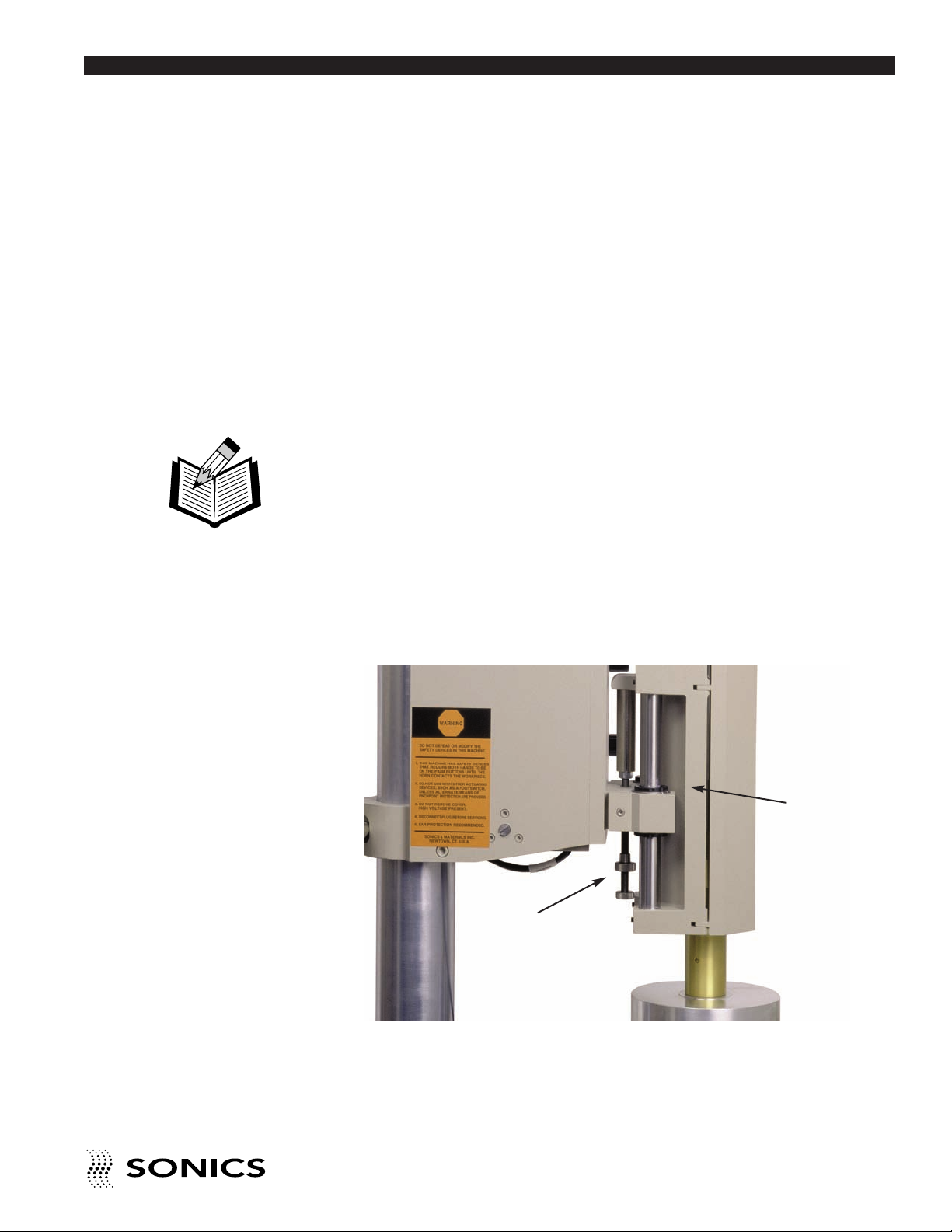
POSITIVE STOP ADJUSTMENT
The positive stop is set to limit the downward travel of the horn to
approximately 75%. Readjustments may be required. Coarse adjustment of
the clearance between the face of the horn and part should be made using
the elevation control. Fine adjustment should be made using the positive stop.
The positive stop can adjust vertical positioning with a 4" stroke (or optional
6" stroke).
CONVERTER
HOUSING
POSITIVE STOP
ADJUSTMENT KNOB
The positive stop adjustment knob is located behind the converter housing.
Turning the knob clockwise will decrease downward travel distance. Turning
the knob counterclockwise will increase the downward travel distance. When
making any adjustments be aware of the necessary clearances required.
• • • • • • • • • • • • • • • • • • • • • • • • • • • • • • • • • • • • • • • • • • • • • • • • • • • • • • • • • • • • • • • • • • • • • • • • • • • • • • • • • • • • • • • • • • • • • • • • • • • • • • • • • • • •
I N S T R U C T I O N M A N U A L • M O D E L 1 5 9 5 / 1 5 9 6
15
Page 17

O P E R A T I O N
Go To Top Of Document
ACTUATION
The 1595 press is equipped with two maintained anti-repeat (non-tie-down)
palm buttons, one located on the left and one on the right side of the base of
the press. Both palm buttons must be pressed simultaneously to activate the
press to cycle the welder. To operate the press, follow these simple steps:
The equipment has
safety devices that
require both hands to
be on the palm buttons
until the horn contacts
the workpiece. Do not
defeat or modify
these safety devices.
NOTE: Power supply
cannot be shut off once
the weld cycle has
started. Termination of
cycle can only be
achieved by using the
EMERGENCY STOP
button.
1. Make sure the column clamps are locked.
2. Depress both black palm buttons simultaneously.
3. Once the horn comes in contact with the part and the ultrasonics are
activated, release the palm buttons. If you release the buttons before
contact is made, the head will immediately return to its “home” position.
The operation of the 1596 actuator is controlled by the automated system. A
four-wire actuation cable is provided which ties into the output side of a PLC,
or other system controlling device. Momentary two wire closure from a dry
source will initiate the welder’s cycle. For more information, refer to the power
supply manual and the included wiring diagrams.
EMERGENCY STOP
To abort the 1595 press during welding, simply press the red EMERGENCY
STOP button located at the front center of the press base.
Once the EMERGENCY STOP button has been depressed, the head will
retract and return to its “home” position, remaining there until the button is
released. Simply rotate the EMERGENCY STOP button to the right 1/4 turn
to release the press for further operation.
For the 1596 actuator, a four-wire actuation cable contains two normally
closed wires which control the emergency stop function. For more
information, refer to the power supply manual and the included wiring
diagrams.
Do not use with a
footswitch unless
alternate means of
pinch-point protection is
provided.
• • • • • • • • • • • • • • • • • • • • • • • • • • • • • • • • • • • • • • • • • • • • • • • • • • • • • • • • • • • • • • • • • • • • • • • • • • • • • • • • • • • • • • • • • • • • • • • • • • • • • • • • • • • •
16
I N S T R U C T I O N M A N U A L • M O D E L 1 5 9 5 / 1 5 9 6
Page 18
F I N E A D J U S T M E N T S
Go To Top Of Document
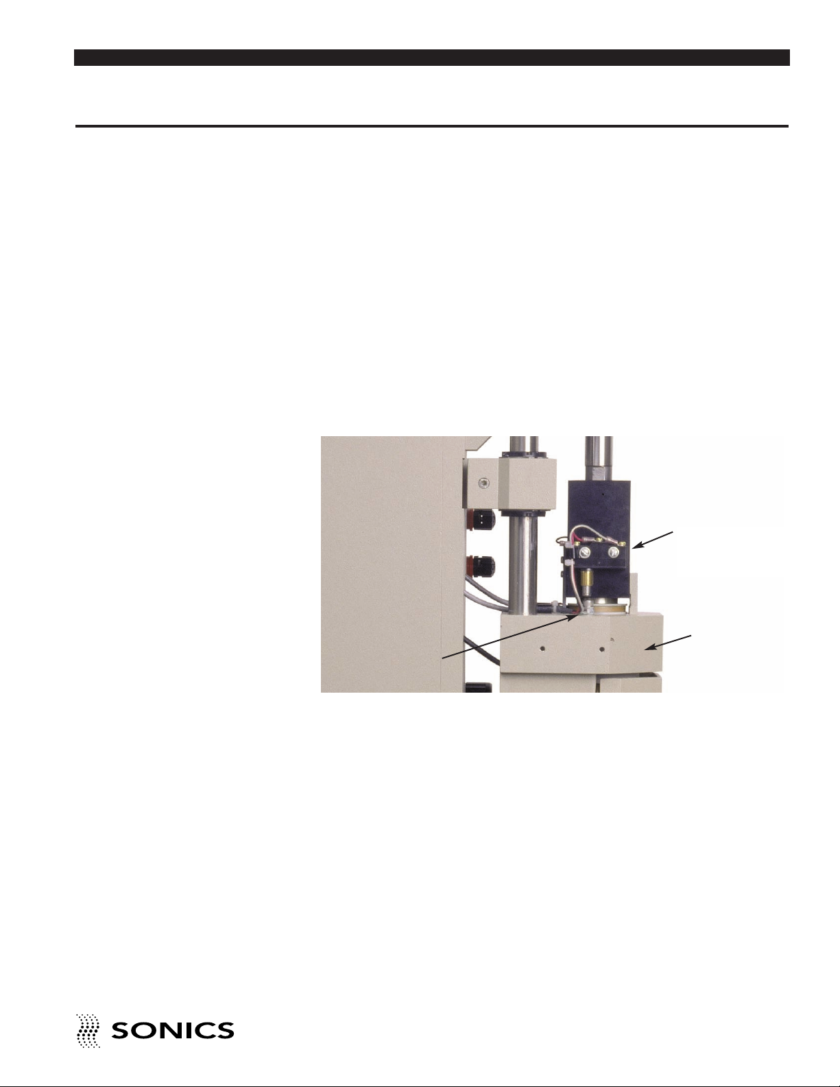
PRESSURE SWITCH ADJUSTMENT
For systems mounted in the normal vertical position with downward travel, no
adjustment should be necessary. The minimum trigger pressure is factory set
to approximately 10-12 psig (69 kPa/.7 bar - 83 kPa/.8 bar).
However, if the minimum trigger pressure requires recalibration or readjustment, observe the following procedure:
1. Maintain air pressure and unplug the power supply from the electrical
source.
2. Remove the four screws holding the five-sided cover.
3. Loosen the jam nut holding the 8-32 cap screw in place.
4. Rotate the cap screw counter-clockwise (up) until the Pressure Switch
closes.
PRESSURE
SWITCH
TOP OF
CAP SCREW
5. Next rotate the cap screw clockwise (down) until the Pressure Switch
opens.
6. Rotate cap screw clockwise (down) 1/4 turn past the Pressure Switch
open position.
7. Tighten the jam nut to lock cap screw in position.
8. Replace the cover and four screws.
9. Plug the power supply into the electrical source.
10. Cycle the welder.
A press actuating in an upward direction should be set to trigger at a minimum
of 14-16 psig (a value which is nominally factory set only if “Sonics” is notified
prior to purchase that the press will be used for vertical welding). Lower
values may affect trigger performance where false triggering may be
observed.
CONVERTER
HOUSING
• • • • • • • • • • • • • • • • • • • • • • • • • • • • • • • • • • • • • • • • • • • • • • • • • • • • • • • • • • • • • • • • • • • • • • • • • • • • • • • • • • • • • • • • • • • • • • • • • • • • • • • • • • • •
I N S T R U C T I O N M A N U A L • M O D E L 1 5 9 5 / 1 5 9 6
17
Page 19

NOTE: Consult the
Go To Top Of Document
Applications Manual or
call our Applications
Lab for proper booster
selection.
UPPER LIMIT SWITCH
The optional Upper Limit Switch may be used as a safety interlock in
automation to prevent the movement of material handling equipment
(indexing) when the horn is down. It also may be used to initiate the
movement of material handling equipment when the horn is up. The Upper
Limit Switch is located opposite the Pressure Switch.
The Upper Limit Switch is factory set and should be suitable for all
applications.
BOOSTER SELECTION
The first step in optimizing welding conditions is to select a booster which will
provide the necessary amplitude. For parts 2" (50.8mm) in diameter or
greater, start with a moderate amplitude booster such as a green. Determine
optimum amplitude by welding a few parts, and repeat the procedure with
boosters giving higher or lower amplitude. If there appears to be little or no
difference, use the booster giving the highest amplitude.
Six standard boosters, color coded or engraved for ease of identification, are
available either to increase or decrease the amplitude.
High gain boosters,
such as silver and black
in combination with
high gain horns can
result in the horn
cracking or failing. See
note above.
BOOSTERS
Color Part No. Gain Amplitude Effect
Black BHN16TBK 2.50 Increase
Silver BHN16TSI 2.00 Increase
Gold BHN16GD 1.50 Increase
Brown BHN16BR 1.25 Increase
Green BHN16GR 0 No Change
Purple BHN23PU 0.75 Decrease
• • • • • • • • • • • • • • • • • • • • • • • • • • • • • • • • • • • • • • • • • • • • • • • • • • • • • • • • • • • • • • • • • • • • • • • • • • • • • • • • • • • • • • • • • • • • • • • • • • • • • • • • • • • •
18
I N S T R U C T I O N M A N U A L • M O D E L 1 5 9 5 / 1 5 9 6
Page 20

NOTE: Contact
Go To Top Of Document
between the booster
and horn should be
parallel. When
encountering symptoms
such as loud noises or
tuning difficulties,
examine the booster /
horn interfaces for
parallelism, corrosion,
galling or foreign
deposits. Also check
the tightness of the
stud.
PRESSURE
During the welding process, sufficient pressure should be applied to the part
so that the mating surfaces contact each other. If the pressure is too low, the
process will run inefficiently causing unnecessarily long weld time cycles,
marking of the parts or poor welding. If the pressure is too high, the horn may
stop vibrating, the part(s) might fracture, or the power supply might overload.
Refer to the Applications manual for additional information on pressure
settings. In general, a starting setting of between 25-30 psig (172 kPa/1.7 207 kPa/2 bar) can be used as a guideline, but you will need to adjust the air
pressure to a desired setting based upon the application results.
RE-ESTABLISHING PROPER BOOSTER / HORN INTERFACES
To re-establish proper interfaces, follow these instructions:
1. Using open-ended wrenches, separate the booster from the horn. Clean
each item and then examine interfaces for irregularities (scoring).
2. If irregularities are present, remove the stud.
3. Tape a sheet of 400 grit emery cloth to a smooth, flat surface. (Do not use
coarser than 400 grit.)
4. Grasp the lower portion of the booster or horn and move it across the
emery cloth. To ensure proper lapping, a) hold the part straight, b) apply
light downward pressure, and c) move in one direction only in a figure 8
pattern.
Repeat the figure 8 pattern once more.
DO NOT use anything
coarser than 400 grit
emery cloth.
• • • • • • • • • • • • • • • • • • • • • • • • • • • • • • • • • • • • • • • • • • • • • • • • • • • • • • • • • • • • • • • • • • • • • • • • • • • • • • • • • • • • • • • • • • • • • • • • • • • • • • • • • • • •
I N S T R U C T I O N M A N U A L • M O D E L 1 5 9 5 / 1 5 9 6
19
Page 21

NOTE: Machining of
Go To Top Of Document
booster / horn may
alter the ability to tune
the component to the
system. System
inoperation may occur.
5. Then, rotate the booster or horn 1/3 of a turn in a clockwise direction and
then repeat step 4.
6. Repeat step 5.
7. Using wire brush, clean stud, then replace securely. Tighten new stud to
the recommended torque specifications on page 13.
• • • • • • • • • • • • • • • • • • • • • • • • • • • • • • • • • • • • • • • • • • • • • • • • • • • • • • • • • • • • • • • • • • • • • • • • • • • • • • • • • • • • • • • • • • • • • • • • • • • • • • • • • • • •
20
I N S T R U C T I O N M A N U A L • M O D E L 1 5 9 5 / 1 5 9 6
Page 22

M A I N T E N A N C E
Go To Top Of Document
REPAIRS / SERVICE
If problems are encountered, contact our Service Department as follows:
Phone: 1-800-745-1105 • 1-203-270-4600
Fax: 1-203-270-4610
NOTE: If packing unit
for return shipment,
DO NOT use
styrofoam “peanuts.”
E-Mail: [email protected]
It is suggested that a system in need of repair be sent back to the factory, with
a written description pertaining to the nature of the problem.
Always contact the factory for return authorization before shipping any
instrument. Include date of purchase, model number, and serial number. For
units not covered by the warranty, a purchase order should be forwarded to
avoid unnecessary delay. Care should be exercised to provide adequate
packing to insure against possible damage in shipment. The system should
be sent with all transportation charges prepaid and return method of shipment
indicated.
• • • • • • • • • • • • • • • • • • • • • • • • • • • • • • • • • • • • • • • • • • • • • • • • • • • • • • • • • • • • • • • • • • • • • • • • • • • • • • • • • • • • • • • • • • • • • • • • • • • • • • • • • • • •
I N S T R U C T I O N M A N U A L • M O D E L 1 5 9 5 / 1 5 9 6
21
Page 23

W A R R A N T Y
Go To Top Of Document
Sonics & Materials, Inc., hereinafter referred to as “Sonics,” warrants its
products for a period of one year from the date of shipment against defect in
material and workmanship under normal installation, use, and maintenance
as described in the operating instructions which accompany such equipment.
During the warranty period, “Sonics” will, at its option, as the exclusive
remedy, either repair or replace without charge for material and labor, the
part(s) which prove upon our examination to be defective, provided the
defective unit is returned to us properly packed with all transportation charges
prepaid.
Ultrasonic welding horns constructed of titanium or aluminum are guaranteed
against defects for a period of one year from date of shipment. “Sonics” will
repair or replace a cracked or defective horn once without charge, if failure
occurs within the warranty period.
Ultrasonic welding horns constructed of steel are guaranteed against defects
for a period of ninety days from date of shipment. “Sonics” will repair or
replace a cracked or defective steel horn once at a charge of 50% of the
original purchase price, if failure occurs within the warranty period.
LIMITATION OF WARRANTY
This warranty is in lieu of any other warranties, either express, implied, or
statutory. “Sonics” neither assumes nor authorizes any person to assume for
it any other obligation or liability in connection with the sale of its products.
“Sonics” hereby disclaims any warranty or merchantability or fitness for a
particular purpose. No person or company is authorized to change, modify,
or amend the terms of this warranty in any manner or fashion whatsoever.
Under no circumstances shall “Sonics” be liable to the purchaser or to any
other person for any incidental or consequential damages or loss of profit or
product resulting from any malfunction or failure of this “Sonics” product.
This warranty does not apply to equipment which has been subject to
unauthorized repair, misuse, abuse, negligence or accident. Equipment
which, in our judgment, shows evidence of having been used in violation of
operating instructions, or which has had the serial number altered or
removed, will be ineligible for service under this warranty.
No liability is assumed for expenses or damages resulting from interruptions
in operation of the product or damages to material in process.
“Sonics” equipment is designed for maximum operator safety and
incorporates built-in safety devices. Any modifications to these safety features
will void the warranty. “Sonics” assumes no responsibilities for consequential
damages incurred due to modifications to the said equipment.
• • • • • • • • • • • • • • • • • • • • • • • • • • • • • • • • • • • • • • • • • • • • • • • • • • • • • • • • • • • • • • • • • • • • • • • • • • • • • • • • • • • • • • • • • • • • • • • • • • • • • • • • • • • •
22
I N S T R U C T I O N M A N U A L • M O D E L 1 5 9 5 / 1 5 9 6
Page 24

“Sonics” reserves the right not to warrant horns of unusual or experimental
Go To Top Of Document
design which in our judgment are more likely to fail in use.
This warranty does not cover equipment used for applications requiring metalto-metal contact with weld time in excess of 1 second.
Data supplied in the instruction manual has been verified and validated and
is believed adequate for the intended use of the equipment. If the equipment
or procedures are used for purposes other than those specified herein,
confirmation of their validity and suitability should be obtained in writing from
“Sonics.”
• • • • • • • • • • • • • • • • • • • • • • • • • • • • • • • • • • • • • • • • • • • • • • • • • • • • • • • • • • • • • • • • • • • • • • • • • • • • • • • • • • • • • • • • • • • • • • • • • • • • • • • • • • • •
I N S T R U C T I O N M A N U A L • M O D E L 1 5 9 5 / 1 5 9 6
23
Page 25

Sonics & Materials, Inc.
Corporate Headquarters European Office
53 Church Hill Road • Newtown, CT 06470 USA 22 ch du Vernay • CH - 1196 Gland, Switzerland
203.270.4600 • 800.745.1105 • 203.270.4610 fax (41) (0) 22/364 1520 • (41) (0) 22/364 2161 fax
Go To Top Of Document
 Loading...