


Model GXE
Power Supply
I N S T R U C T I O N M A N U A L
Sonics & Materials, Inc.

WARNING
SAFETY PRECAUTIONS
READ BEFORE INSTALLING OR USING THE EQUIPMENT
This system has been designed to assure maximum operator safety. However, no design can completely protect against improper usage. For maximum safety and equipment protection, observe the following warnings at all times and read the instruction manual carefully before you attempt to operate the equipment.
–High voltage is present in the equipment. Disconnect plug before removing cover or servicing.
–Make sure equipment is properly grounded with a 3-prong plug. Before plugging in equipment, test outlet for proper earth grounding.
–Ultrasonic welders operate above normal audibility for most people. Ear protection is recommended.
Sonics & Materials, Inc.
Corporate Headquarters |
European Office |
53 Church Hill Road • Newtown, CT 06470 USA |
13, Rue Pre-de-la-Fontaine • CH - 1217 Meyrin/Satigny, Switzerland |
203.270.4600 • 800.745.1105 • 203.270.4610 fax |
(41) (0) 22/364 1520 • (41) (0) 22/364 2161 fax |
www.sonics.com • info@sonics.com |
europe@sonicsandmaterials.ch |
Information contained in this manual is subject to change without notice. Sonics & Materials, Inc. is not responsible for any typographic errors.
© Sonics & Materials, Inc. 2010 |
Printed in U.S |
Rev 01, 9/10 |
|
• • • • • • • • • • • • • • • • • • • • • • • • • • • • • • • • • • • • • • • • • • • • • • • • • • • • • • • • • • • • • • • • • • • • • • • • • • • • • • • • • • • • • • • • • • • • • • • • • • • • • • • • • • • • |
|
|
I N S T R U C T I O N M A N U A L • M O D E L G XE P O W E R S U P P LY |
1 |
Go To Topop OfOfDocuDocumente t

TABLE OF CONTENTS
IMPORTANT SERVICE LITERATURE . . . . . . . . . . . . . . . . . . . . . . . . . . . .4
Manual Change Information . . . . . . . . . . . . . . . . . . . . . . . . . . . . . .4
UNPACKING AND INSPECTION . . . . . . . . . . . . . . . . . . . . . . . . . . . . . . . .5
Visible Loss or Damage . . . . . . . . . . . . . . . . . . . . . . . . . . . . . . . . .5
Concealed Loss or Damage . . . . . . . . . . . . . . . . . . . . . . . . . . . . . .5
INTRODUCTION . . . . . . . . . . . . . . . . . . . . . . . . . . . . . . . . . . . . . . . . . . . . .6
OVERVIEW OF ULTRASONIC PLASTICS ASSEMBLY . . . . . . . . . . . . . . .6
What is Ultrasonics? . . . . . . . . . . . . . . . . . . . . . . . . . . . . . . . . . . . .6
Principal of Ultrasonic Assembly . . . . . . . . . . . . . . . . . . . . . . . . . .6
Ultrasonic Assembly Systems . . . . . . . . . . . . . . . . . . . . . . . . . . . .6
GLOSSARY OF ULTRASONIC TERMS . . . . . . . . . . . . . . . . . . . . . . . . . . .8
INSTALLATION . . . . . . . . . . . . . . . . . . . . . . . . . . . . . . . . . . . . . . . . . . . . . .9
Electrical Power Requirements . . . . . . . . . . . . . . . . . . . . . . . . . . . .9
Setting Up . . . . . . . . . . . . . . . . . . . . . . . . . . . . . . . . . . . . . . . . . . . .9
Electrical Connections . . . . . . . . . . . . . . . . . . . . . . . . . . . . . . . . .10
Cable Connections – For Models with 700 to 2200 Watts Power . . .11
Cable Connections – For Models with 3000 or 4000 Watts Power . .12
Available Converters . . . . . . . . . . . . . . . . . . . . . . . . . . . . . . . . . . .13
OPERATING PROCEDURES . . . . . . . . . . . . . . . . . . . . . . . . . . . . . . . . . .14
Front Panel Controls and Indicators . . . . . . . . . . . . . . . . . . . . . . .14
Keying in Parameters . . . . . . . . . . . . . . . . . . . . . . . . . . . . . . . . . .16
Operational Features . . . . . . . . . . . . . . . . . . . . . . . . . . . . . . . . . . .17
Starting up the Power Supply . . . . . . . . . . . . . . . . . . . . . . . . . . . .17
Initial Operation . . . . . . . . . . . . . . . . . . . . . . . . . . . . . . . . . . . . . . .18
Ready Screens . . . . . . . . . . . . . . . . . . . . . . . . . . . . . . . . . . . . . . .18
Relationship of Time and Energy Settings . . . . . . . . . . . . . . . . . .19
Time Settings . . . . . . . . . . . . . . . . . . . . . . . . . . . . . . . . . . . . . . . .20
Energy Settings . . . . . . . . . . . . . . . . . . . . . . . . . . . . . . . . . . . . . . .21
Amplitude/Pressure . . . . . . . . . . . . . . . . . . . . . . . . . . . . . . . . . . . .22
Trigger . . . . . . . . . . . . . . . . . . . . . . . . . . . . . . . . . . . . . . . . . . . . . .22
ADDITIONAL FEATURES AND FUNCTIONS . . . . . . . . . . . . . . . . . . . . .23
Job Storage . . . . . . . . . . . . . . . . . . . . . . . . . . . . . . . . . . . . . . . . . .23
Frequency Display . . . . . . . . . . . . . . . . . . . . . . . . . . . . . . . . . . . . .24
Overload Protection . . . . . . . . . . . . . . . . . . . . . . . . . . . . . . . . . . .24
KEYPAD SECURITY . . . . . . . . . . . . . . . . . . . . . . . . . . . . . . . . . . . . . . . . .25
PRINT LINE OUTPUT . . . . . . . . . . . . . . . . . . . . . . . . . . . . . . . . . . . . . . . .26
• • • • • • • • • • • • • • • • • • • • • • • • • • • • • • • • • • • • • • • • • • • • • • • • • • • • • • • • • • • • • • • • • • • • • • • • • • • • • • • • • • • • • • • • • • • • • • • • • • • • • • • • • • • •
I N S T R U C T I O N M A N U A L • M O D E L G X E P O W E R S U P P LY |
2 |
Go To Top Of Document

AUTOMATION INTERFACE & I/O CONTROLS . . . . . . . . . . . . . . . . . . . .28
External Job Address Lines . . . . . . . . . . . . . . . . . . . . . . . . . . . . .30
MAINTENANCE . . . . . . . . . . . . . . . . . . . . . . . . . . . . . . . . . . . . . . . . . . . . .31
General . . . . . . . . . . . . . . . . . . . . . . . . . . . . . . . . . . . . . . . . . . . . .31
Repairs / Service . . . . . . . . . . . . . . . . . . . . . . . . . . . . . . . . . . . . . .31
WARRANTY . . . . . . . . . . . . . . . . . . . . . . . . . . . . . . . . . . . . . . . . . . . . . . . .32
Limitation of Warranty . . . . . . . . . . . . . . . . . . . . . . . . . . . . . . . . . .32
APPENDIX . . . . . . . . . . . . . . . . . . . . . . . . . . . . . . . . . . . . . . . . . . . . . . . . .33
Print Line Output Data Items . . . . . . . . . . . . . . . . . . . . . . . . . . . .33
Automation Interface & I/O Controls . . . . . . . . . . . . . . . . . . . . . . .36
Source/Sink Inputs and Outputs . . . . . . . . . . . . . . . . . . . . . . . . . .36
Source/Sink Digital I/O Configuration . . . . . . . . . . . . . . . . . . . . . .37
Sinking Output to PLC Input Diagram . . . . . . . . . . . . . . . . . . . . .38
PLC Output to Sinking Input Diagram . . . . . . . . . . . . . . . . . . . . .38
PLC Output to Sourcing Input Diagram . . . . . . . . . . . . . . . . . . . .38
Two Isolated Loop Supplies . . . . . . . . . . . . . . . . . . . . . . . . . . . . .39
I/O Timing Diagram – Automated Controls . . . . . . . . . . . . . . . . . .39
PLC Sample Code . . . . . . . . . . . . . . . . . . . . . . . . . . . . . . . . . . . .40
Drawings . . . . . . . . . . . . . . . . . . . . . . . . . . . . . . . . . . . . . . . . . . . .42
G-Series Switches . . . . . . . . . . . . . . . . . . . . . . . . . . . . . . . . . . . . .50
• • • • • • • • • • • • • • • • • • • • • • • • • • • • • • • • • • • • • • • • • • • • • • • • • • • • • • • • • • • • • • • • • • • • • • • • • • • • • • • • • • • • • • • • • • • • • • • • • • • • • • • • • • • •
I N S T R U C T I O N M A N U A L • M O D E L G X E P O W E R S U P P LY |
3 |
Go To Top Of Document

IMPORTANT SERVICE LITERATURE
The system supplied with this instruction manual is constructed of the finest material and the workmanship meets the highest manufacturing standards. It has been thoroughly tested and inspected before leaving the factory and when used in accordance with the procedures outlined in this manual, will provide you with many years of safe and dependable service.
NOTE: Please read
carefully before |
MANUAL CHANGE INFORMATION |
|
||||
operating the |
We continually strive to |
be at |
the |
forefront of |
the latest electronic |
|
equipment, then forward |
||||||
developments by adding |
circuit |
and |
component |
improvements to our |
||
to your service |
||||||
|
|
|
|
|
||
equipment as soon as they are developed and tested.
department.
Sometimes, due to printing and shipping requirements, we cannot incorporate these changes immediately into printed manuals. Hence, your manual may contain new change information. Change information, if any, is located in the Appendix.
We reserve the right to make any changes in the design or construction of our equipment at any time, without incurring any obligation to make any change whatsoever in units previously delivered.
The technical data and schematics in the manual are for informational purposes only and may not reflect the current configuration being shipped from our factory. Upon formal request, complete and up-to-date information can be provided from the factory free of charge.
• • • • • • • • • • • • • • • • • • • • • • • • • • • • • • • • • • • • • • • • • • • • • • • • • • • • • • • • • • • • • • • • • • • • • • • • • • • • • • • • • • • • • • • • • • • • • • • • • • • • • • • • • • • •
I N S T R U C T I O N M A N U A L • M O D E L G X E P O W E R S U P P LY |
4 |
Go To Top Of Document

UNPACKING AND INSPECTION
NOTE: We recommend keeping all carton(s) and packing material in case it might be necessary to move the equipment, or to ship it for repair.
Before unpacking the equipment, check the shipping carton for any visible damage. If you see any, be sure to follow the procedures described below under “Visible Loss or Damage.” Otherwise, proceed to remove the equipment from the carton. Before storing any packing material, check it carefully for small parts. Then perform a visual inspection of the equipment to detect any evidence of damage which might have occurred during shipment. Check the following:
1.all components against the enclosed packing list,
2.all module plug-in units,
3.all wire plug-in connections.
The equipment was carefully packed and thoroughly inspected before leaving our factory. All units are tested and checked for problems prior to shipping. It is asked that when a problem does occur that all parts and components be inspected for damage (especially when the unit is not in working order when received). Responsibility for safe delivery was assumed by the carrier upon acceptance of the shipment. Claims for loss of damage sustained in transit must therefore be made upon the carrier, as follows:
VISIBLE LOSS OR DAMAGE
Any external evidence of loss or damage must be noted on the freight bill or express receipt, and signed by the carrier’s agent. Failure to adequately describe such external evidence of loss or damage may result in the carrier’s refusal to honor a damage claim. The form required to file such a claim will be supplied by the carrier.
CONCEALED LOSS OR DAMAGE
Concealed loss or damage means loss or damage which does not become apparent until the merchandise has been unpacked. The contents might have been damaged in transit due to rough handling even though the container may not show external damage. When the damage is discovered upon unpacking, make a written request for inspection by the carrier’s agent within 48 hours of the delivery date. Then file a claim with the carrier since such damage is the carrier’s responsibility. The form required to file such a claim will be supplied by the carrier. Do not destroy packing materials, or move material from one location to another before the carrier makes their inspection.
If the system or any unit is damaged, notify Sonics. Sonics will arrange for repair or replacement of damaged equipment without waiting for the claim against the carrier to be settled, provided a new purchase order is issued to cover the repair or replacement costs. Should any damage, shortage or discrepancy exist, please notify us immediately.
• • • • • • • • • • • • • • • • • • • • • • • • • • • • • • • • • • • • • • • • • • • • • • • • • • • • • • • • • • • • • • • • • • • • • • • • • • • • • • • • • • • • • • • • • • • • • • • • • • • • • • • • • • • •
I N S T R U C T I O N M A N U A L • M O D E L G X E P O W E R S U P P LY |
5 |
Go To Top Of Document

INTRODUCTION
The GXE power supply is an ultrasonic generator with automatic frequency tuning and a built-in Microprocessor that features time and energy controls. The Microprocessor is programmed with a multi-function keypad and information is displayed on the back-lit liquid crystal display (LCD). This power supply can be used with a pneumatic press or actuator, or with a stand-alone converter.
OVERVIEW OF ULTRASONIC PLASTICS ASSEMBLY
WHAT IS ULTRASONICS?
Ultrasonics refers to vibrational waves with a frequency above the human audible range which is usually above 18,000 cycles per second (Hz).
PRINCIPLE OF ULTRASONIC ASSEMBLY
The basic principle of ultrasonic assembly involves conversion of high frequency electrical energy to high frequency mechanical energy in the form of reciprocating vertical motion which, when applied to a thermoplastic, generates frictional heat at the plastic/plastic or plastic/metal interface. In ultrasonic welding, this frictional heat melts the plastic, allowing the two surfaces to fuse together; in ultrasonic staking or insertion, the controlled flow of molten plastic is used to capture or lock another material in place (staking) or encapsulate a metal insert (insertion).
ULTRASONIC ASSEMBLY SYSTEMS
Sonics ultrasonic assembly systems are generally composed of the following major elements: a power supply, converter, booster, horn, pneumatic press and holding fixture, as detailed in the diagram on the next page. A review of this diagram will help you understand the basic elements involved in the assembly process and their relation to each other.
• • • • • • • • • • • • • • • • • • • • • • • • • • • • • • • • • • • • • • • • • • • • • • • • • • • • • • • • • • • • • • • • • • • • • • • • • • • • • • • • • • • • • • • • • • • • • • • • • • • • • • • • • • • •
I N S T R U C T I O N M A N U A L • M O D E L G X E P O W E R S U P P LY |
6 |
Go To Top Of Document

SONICS ULTRASONIC ASSEMBLY SYSTEMS
Power Supply/Generator
Actuator/Press
Provides compressive force and mounting for Converter, Booster, Horn assembly
50/60 Hz
Electrical power
Generates ultrasonic electrical energy (15/20/40 kHz)
Ultrasonic
electrical energy
Converter
Transforms ultrasonic electrical energy to ultrasonic mechanical vibrations
Ultrasonic Vibrations
Booster
Increases or decreases amplitude
Ultrasonic Vibrations
Horn
Contacts and transfers vibrational energy to plastic part
Holding Fixture
Aligns and supports part
Ultrasonic Vibrations
Plastic part
• • • • • • • • • • • • • • • • • • • • • • • • • • • • • • • • • • • • • • • • • • • • • • • • • • • • • • • • • • • • • • • • • • • • • • • • • • • • • • • • • • • • • • • • • • • • • • • • • • • • • • • • • • • •
I N S T R U C T I O N M A N U A L • M O D E L G X E P O W E R S U P P LY |
7 |
Go To Top Of Document

GLOSSARY OF ULTRASONIC TERMS
POWER SUPPLY/GENERATOR – The solid state power supply converts standard 50/60 Hz electrical energy to 15,000 Hz, 20,000 Hz or 40,000 Hz (15/20/40 kHz) electrical energy.
ACTUATOR/WELDING PRESS – The pneumatic actuator provides compressive force and mounting for the converter, booster and horn assembly. The tabletop press consists of a base assembly, column and actuator (head).
CONVERTER – The converter changes the high frequency electrical energy supplied by the power supply to high frequency mechanical vibrations.
BOOSTER – Successful ultrasonic welding often depends on having the right amplitude at the horn face. Often it is not possible to design a horn which has both the necessary shape and required gain (ratios of input amplitude to output amplitude). In such cases, a booster is placed between the converter and the horn to either increase or decrease the amplitude of the horn. In addition to changing/maintaining the amplitude, the booster provides support and alignment in the welding system.
HORN – The horn is a tuned component of the system which comes in contact with the parts to be assembled. The horn 1) transfers the ultrasonic vibrations produced from the converter to the parts being welded, and 2) applies necessary force to the assembly while the material resolidifies.
HOLDING FIXTURE – The holding fixture or nest assures proper alignment and support of the parts being assembled.
• • • • • • • • • • • • • • • • • • • • • • • • • • • • • • • • • • • • • • • • • • • • • • • • • • • • • • • • • • • • • • • • • • • • • • • • • • • • • • • • • • • • • • • • • • • • • • • • • • • • • • • • • • • •
I N S T R U C T I O N M A N U A L • M O D E L G X E P O W E R S U P P LY |
8 |
Go To Top Of Document

INSTALLATION
The line cord of the controller/power supply is equipped with a 3- prong, grounding plug. Do not, under any circumstances, remove the ground prong. The plug must be plugged into a mating 3-prong, grounding type outlet.
NOTE: If power supply is to be run continuously, air cooling of the converter and horn is required. Use clean, dry compressed air filtered down to 5 microns (supplied to converter fitting – see page 13).
ELECTRICAL POWER REQUIREMENTS
The power supply requires a fused, single-phase, standard 3-terminal grounding type receptacle capable of supplying the requisite voltage and current. Refer to the table below for power specification.
POWER SPECIFICATIONS
|
|
|
|
|
|
|
Power Rating/ |
|
Fuse Ratings |
|
|
Model |
Frequency |
115 |
vac |
230 vac |
|
GXE400-40 |
400w - 40 kHz |
15 amps |
10 amps |
||
|
|
|
|
|
|
GXE800-40 |
800w - 40 kHz |
15 amps |
10 amps |
||
|
|
|
|
|
|
GXE1200-20 |
1200w - 20 kHz |
15 amps |
10 amps |
||
|
|
|
|
|
|
GXE1700-20 |
1700w - 20 kHz |
N/A |
20 amps |
||
|
|
|
|
|
|
GXE2200-20 |
2200w - 20 kHz |
N/A |
20 amps |
||
|
|
|
|
|
|
GXE3500-20 |
3500w - 20 kHz |
N/A |
30 amps |
||
|
|
|
|
|
|
GXE2200-15 |
2200w - 15 kHz |
N/A |
20 amps |
||
|
|
|
|
|
|
GXE3500-15 |
3500w - 15 kHz |
N/A |
30 amps |
||
|
|
|
|
|
|
GXE4500-15 |
4500w - 15 kHz |
N/A |
30 amps |
||
|
|
|
|
|
|
|
|
|
|
|
|
SETTING UP
The power supply is a free-standing assembly. It should be installed in a clear, uncluttered location that is free from excessive dirt, dust, corrosive fumes, and temperature and humidity extremes. The selected installation site should be near the electrical power source and away from equipment that generates abnormally high electrical transients. Observe the following additional instructions when installing the equipment:
a.Allow at least 6 inches (152.4mm) at the rear of the power supply for cable connections.
b.Position the power supply so that the front panel controls are visible and readily accessible.
c.The power supply is air cooled; allow sufficient space around the assembly to ensure adequate ventilation. If the power supply must be housed in a confined space, forced air cooling may be necessary to keep surrounding air within acceptable ambient temperature limits. Periodically check the ventilation grille and clean as necessary.
• • • • • • • • • • • • • • • • • • • • • • • • • • • • • • • • • • • • • • • • • • • • • • • • • • • • • • • • • • • • • • • • • • • • • • • • • • • • • • • • • • • • • • • • • • • • • • • • • • • • • • • • • • • •
I N S T R U C T I O N M A N U A L • M O D E L G X E P O W E R S U P P LY |
9 |
Go To Top Of Document
NOTE: Do not plug the power supply into an electrical outlet until all other connections have been made.
ELECTRICAL CONNECTIONS
The standard cable supplied with a Sonics press is 10 feet. Optional extension cables are available up to 15 feet without modification.
When making the initial electrical connections, make sure the power is disconnected and follow these precautions.
1.Do not strain or kink the cables. When going around corners, allow as wide a bend as possible. Do not run the cables parallel to any power line within a distance of less than 1 foot (305 mm).
2.To prevent the possibility of an electrical shock, ensure that the power supply line cord is properly grounded. Also make sure that the voltage rating of the electrical power source matches the power supply requirement (refer to the “Power Specifications” table on preceding page).
3.Check with your electrician if you have any wiring questions.
• • • • • • • • • • • • • • • • • • • • • • • • • • • • • • • • • • • • • • • • • • • • • • • • • • • • • • • • • • • • • • • • • • • • • • • • • • • • • • • • • • • • • • • • • • • • • • • • • • • • • • • • • • • •
I N S T R U C T I O N M A N U A L • M O D E L G X E P O W E R S U P P LY |
10 |
Go To Top Of Document

NOTE: Detailed wiring diagrams are supplied in the Appendix at the back of this manual.
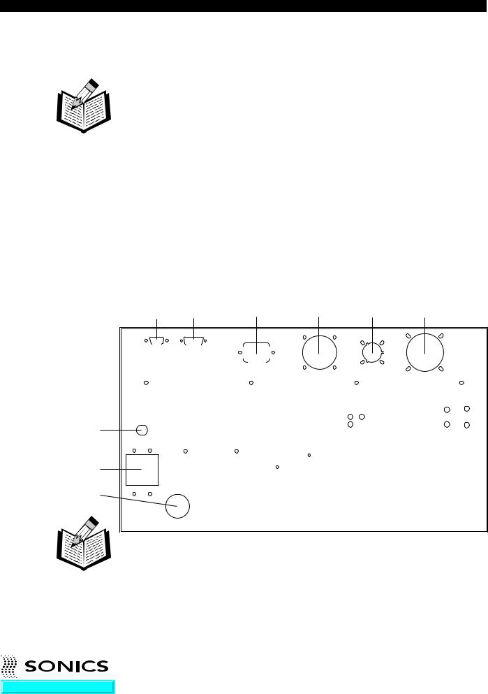
CABLE CONNECTIONS – For Models with 700 to 2200 Watts Power:
Located at the rear of the power supply are the cable connections as illustrated below. (The interconnecting cables will be supplied with your system.)
J1, a round, 12-pin RF cable that connects the welding press or converter to the power supply.
J2, an actuation cable that connects the power supply to a trigger source (press cable or external trigger source.) Refer to wiring diagrams in
Appendix.
The power line cord that plugs into the appropriate electrical outlet.
Once these connections have been made, the power supply is ready for operation. If applicable, be sure to consult your welding press instruction manual to insure that all connections on the press side are correct, and that the press is ready for operation.
NOTE: To see a list of converters that can be connected to the power supply, see the table on the following page.
|
|
|
|
|
|
|
|
|
|
|
|
|
|
|
|
|
|
|
|
|
|
|
|
|
|
|
|
|
|
|
|
|
|
|
|
|
|
|
|
|
|
|
|
||||
Fan |
|||||
|
|
|
|
|
|
Also located at the rear of the power supply are the following:
J5 External I/O
Fuse (0.5 amp - internal low voltage)
Line fuse (based on requirements listed in “Power Specifications” table, page 9),
Line fuse (based on requirements listed in “Power Specifications” table, page 9),
J4 Serial Output
• • • • • • • • • • • • • • • • • • • • • • • • • • • • • • • • • • • • • • • • • • • • • • • • • • • • • • • • • • • • • • • • • • • • • • • • • • • • • • • • • • • • • • • • • • • • • • • • • • • • • • • • • • • •
I N S T R U C T I O N M A N U A L • M O D E L G X E P O W E R S U P P LY |
11 |
Go To Top Of Document
NOTE: Detailed wiring diagrams are supplied in the Appendix at the back of this manual.
CABLE CONNECTIONS – For Models with 3000 or 4000 Watts Power:
Located at the rear of the power supply are the cable connections as illustrated below. (The interconnecting cables will be supplied with your system.)
J1, a round, 12-pin RF cable that connects the welding press or converter to the power supply.
J2, an actuation cable that connects the power supply to a trigger source (press cable or external trigger source.) Refer to wiring diagrams in
Appendix.
The power line cord that plugs into the appropriate electrical outlet.
Once these connections have been made, the power supply is ready for operation. If applicable, be sure to consult your welding press instruction manual to insure that all connections on the press side are correct, and that the press is ready for operation.
NOTE: To see a list of converters that can be connected to the power supply, see the table on the following page.
|
|
|
|
|
|
|
|
||
|
|
|
|
|
|
|
|
|
|
|
|
|
|
|
|
|
|
|
|
|
|
|
|
|
|
|
|
|
|
|
|
|
|
|
|
|
|
|
|
Also located at the rear of the power supply are the following:
J5 External I/O |
J4 |
Serial Output |
|
Fuse (0.5 amp - internal low |
|
J3 |
Linear Encoder |
voltage) |
|
J6 on 15 kHz models only. |
|
|
|||
Circuit breaker |
|
Press motor connector. |
|
• • • • • • • • • • • • • • • • • • • • • • • • • • • • • • • • • • • • • • • • • • • • • • • • • • • • • • • • • • • • • • • • • • • • • • • • • • • • • • • • • • • • • • • • • • • • • • • • • • • • • • • • • • • •
I N S T R U C T I O N M A N U A L • M O D E L G X E P O W E R S U P P LY |
12 |
Go To Top Of Document

AVAILABLE CONVERTERS FOR POWER SUPPLIES
Item No. |
Description |
|
|
CV00016 15 kHz with Button connector (O-ring mount)
CV00161 15 kHz with Lemo connector (O-ring mount)
CV00034 15 kHz with Button connector (O-ring mount) rated up to 4500 watts
CV00341 15 kHz with Lemo connector (O-ring mount) rated up to 4500 watts
CV00015 20 kHz with Button connector (O-ring mount)
CVR0015 20 kHz with Button connector (rigid mount)
CV00151 20 kHz with Lemo connector (O-ring mount)
CVR0151 20 kHz with Lemo connector (rigid mount)
CV00154 20 kHz with Lemo connector and fitting for air cooling (O-ring mount)
CVR0154 20 kHz with Lemo connector and fitting for air cooling (rigid mount)
CV00157 20 kHz with Button connector and fitting for air cooling (O-ring mount)
CVR0157 20 kHz with Button connector and fitting for air cooling (rigid mount)
CV00158 20 kHz Hand Gun with handles and cables (O-ring mount)
CVR0158 20 kHz Hand Gun with handles and cables (rigid mount)
CV00331 20 kHz with Fischer connector
CV00334 20 kHz with Fischer connector and fitting for air cooling
CVR0023 40 kHz with Button connector (rigid mount)
CVR0231 40 kHz with Lemo connector (rigid mount)
CVR0233 40 kHz with SHV connector side mounted (rigid mount)
CVR0234 40 kHz with Lemo connector and fitting for air cooling (rigid mount)
• • • • • • • • • • • • • • • • • • • • • • • • • • • • • • • • • • • • • • • • • • • • • • • • • • • • • • • • • • • • • • • • • • • • • • • • • • • • • • • • • • • • • • • • • • • • • • • • • • • • • • • • • • • •
Go To Top Of Document
I N S T R U C T I O N M A N U A L • M O D E L G X E P O W E R S U P P LY 13

OPERATING PROCEDURES
FRONT PANEL CONTROLS AND INDICATORS
Located on the front panel of the power supply are the following controls and indicators:
1.ON/OFF keys which turn the unit on and off.
2.LCD SCREEN which displays various settings, parameters and prompts as detailed in the following pages. In addition, during the weld process it displays a load meter indicator showing the power level of ultrasonics that is being delivered to the welding press (see #3 below).
3.LOAD METER SCALE from 0 to 100% which (in conjunction with vertical line indicators on LCD display) shows the running power (bar graph at bottom of display) and peak power (single vertical line at top of display) during the weld. Peak power is reported as %Pmax after the cycle (see page 17).
4.TIME key which allows selection and display of time settings and permits adjustment of time duration in .01 second increments (from 00.00 to 99.99 seconds) for five time parameters as follows:
a.Weld time
b.Hold Time
c.Delay time
d.Afterburst Time
e.Time Limit Low
f.Time Limit High
For a complete explanation of these parameters, refer to page 20.
• • • • • • • • • • • • • • • • • • • • • • • • • • • • • • • • • • • • • • • • • • • • • • • • • • • • • • • • • • • • • • • • • • • • • • • • • • • • • • • • • • • • • • • • • • • • • • • • • • • • • • • • • • • •
I N S T R U C T I O N M A N U A L • M O D E L G X E P O W E R S U P P LY |
14 |
Go To Top Of Document

5.DISTANCE key. Option not available with Model GXE.
6.ENERGY key which allows selection and display of the following energy settings and permits adjustment of the energy parameters a. through c. below in 1 joule increments (from 0 to 999,999 joules):
a.Energy Setting
b.Energy Limit Low
c.Energy Limit High
d.Calibration Pulse (on/off)
For a complete explanation of these parameters, refer to page 21.
7.AMPLITUDE/PRESSURE key which controls adjustment of the following amplitude and pressure settings of the system’s high-frequency vibrations over the full operating range. (Major adjustments of amplitude can be made through the use of different boosters – consult your press manual for further information.)
a.Amplitude Setting
b.Amplitude Ramp (only on systems configured for more than 2200 watts)
c.Trigger Force (Press)
8.TRIGGER key which displays and permits selection of the trigger mode from the following options –
a.Delay Timer
b Force/Pressure
c. Pretrigger - Top
9.RECALL/SAVE key which allows up to 15 different jobs to be stored (saved) and recalled or changed upon demand.
10.ARROW keys (Up/Down) which allow scrolling through some menus and also serve as a toggle for displayed parameter options in some menus.
11.TEST key which can be used to test ultrasonic operation and displays idle losses of converter/booster/horn as a percentage of maximum power when key is depressed. Also functions as a frequency display.
12.O.L. RESET key which resets the power supply following an overload condition. Red LED in upper left corner indicates an overload condition exists.
13.0-9 NUMERIC KEY PAD which allows input of numeric data or numeric selection options by pressing the keys.
•• • • • • • • • • • • • • • • • • • • • • • • • • • • • • • • • • • • • • • • • • • • • • • • • • • • • • • • • • • • • • • • • • • • • • • • • • • • • • • • • • • • • • • • • • • • • • • • • • • • • • • • • • • •
I N S T R U C T I O N M A N U A L • M O D E L G X E P O W E R S U P P LY |
15 |
Go To Top Of Document
 Loading...