

Page 1
Page 1 of 8
Architectural Series
™
Introduction
Congratulations on your purchase of the Sonance
®
Architectural Series™ BPS-1 Bandpass Subwoofer
System. The BPS-1 system will add deep, powerful
bass impact to any audio system that includes
Sonance Architectural Series speakers. The BPS-1
cabinet remains completely hidden from view,
delivering its bass energy through a Sonance
Architectural Series Panel Bracket and Architectural
Finish Component that is a discreet complement to the
surrounding architectural space.
The complete BPS-1 Bandpass Subwoofer System is
comprised of a BPS-1 bandpass subwoofer cabinet,
an Adaptor Baffle, a dedicated Sonamp
®
A150 power amplifier, an Architectural Series Panel Bracket and
an Architectural Finish Component, all of which are available separately.
Design and Features
• Delivers powerful, room-filling bass through a small grille that complements the room’s architectural
design.
• Trimless and truly flush-mount installation — the plane of the subwoofer grille is perfectly aligned with
the plane of the ceiling.
• Available Adaptor Baffles allow the BPS-1 to be used with any size round or square Architectural Series
Panel Bracket (even 4”) to match other Architectural Series speakers in the audio system.
• The 8”
woofer driver features a felted paper cone with a rubber surround that should provide years of
reliable high-power operation. This allows the BPS-1 to be installed in a location that will have limited
or no access.
• The very efficient 4th-order bandpass enclosure produces high output over the subwoofer’s entire
frequency range.
• Adaptor Baffles are heavily flared to minimize port noise during high-volume passages.
• The BPS-1 can be used with any separately available Architectural Series Finish Component:
metal (with or without trim) or cloth (with or without trim).
• Sonamp A150 power amplifier (required, available separately) delivers 150 watts of power and
provides flexible connections that integrate the BPS-1 system into any audio system.
A built-in limiter
prevents overdriving the BPS-1’s woofer driver, even when using a single A150 to drive two BPS-1 subwoofer
cabinets.
• Front-panel amplifier controls (volume, crossover frequency, phase) let you fine-tune the woofer’s
performance to match a variety of listening environments and personal preferences.
Box Contents
• (1) BPS-1 Subwoofer Cabinet (with vent tube attached)
• (8)
5
/
16“ x 2” Lag Screws (for attachment to I-joists)
• (8)
5
/
16“ x 3” Lag Screws (for attachment to standard joists)
• (2) Temporary Installation Brackets
• (1) Mounting Hole Drilling Template
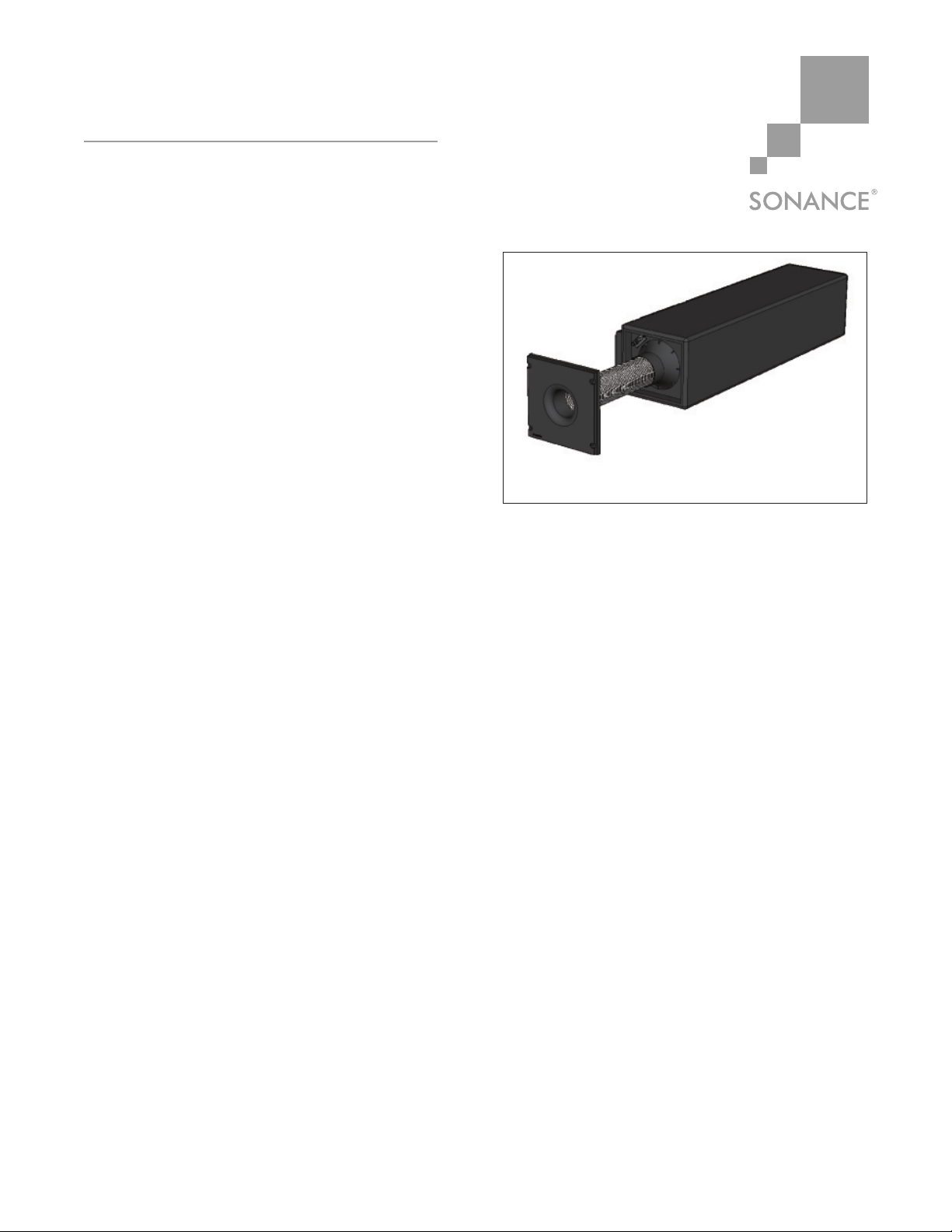
BPS-1 IN-CEILING
SUBWOOFER
I NSTALLATION M ANUAL
Figure 1: BPS-1 Subwoofer (shown with Adaptor Baffle)
Page 2
Page 2 of 8
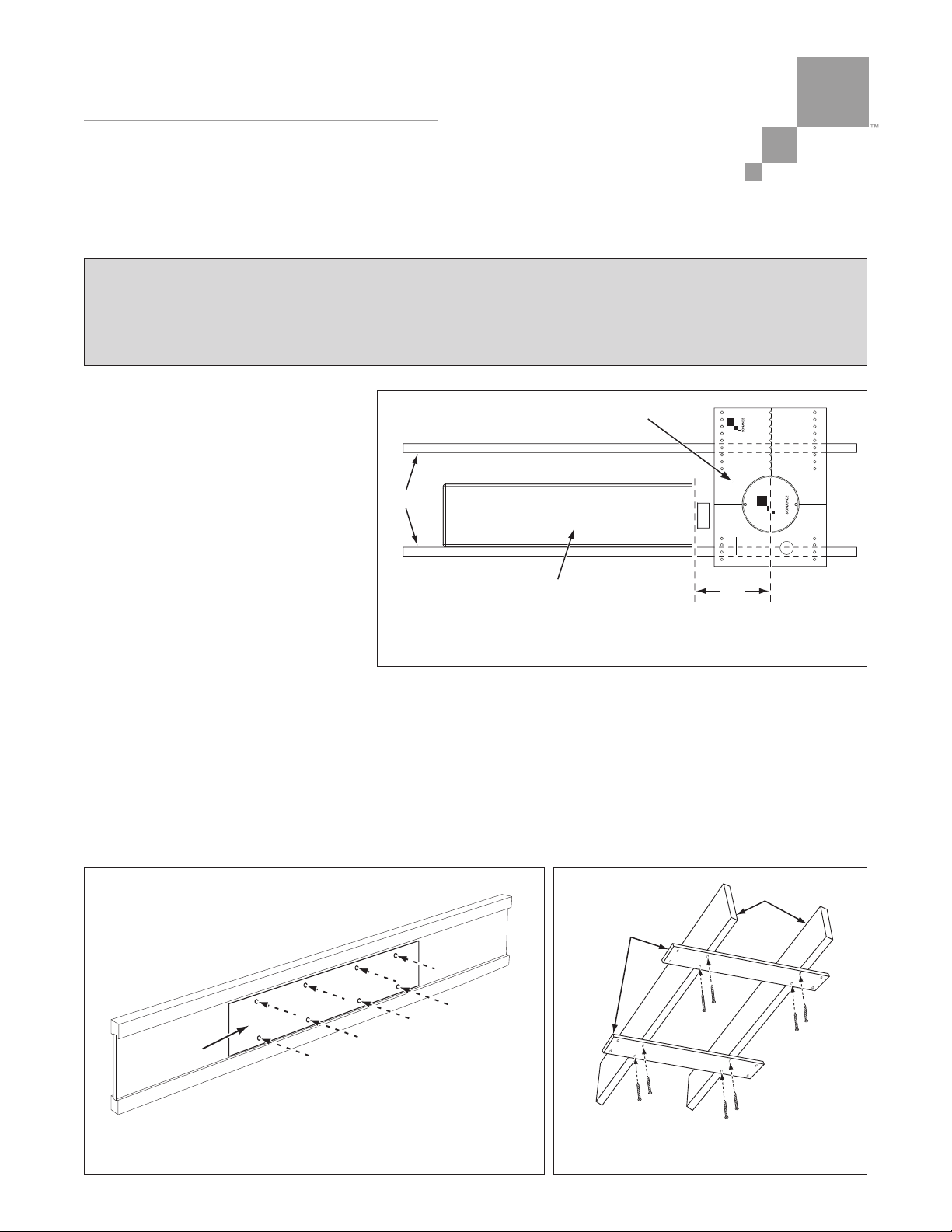
Installing the BPS-1 Cabinet In New Construction
1. Determine the location for the
Architectural Series Panel
Bracket/Grille and install it
according to its instruction manual.
2. Determine the location for the
BPS-1 cabinet.
IMPORTANT: THE CENTER OF
PANEL BRACKET’S SPEAKER OPEN-
ING SHOULD BE APPROXIMATELY
12” FROM VENT TUBE END OF BPS-1
ENCLOSURE (SEE
FIGURE 2
).
MAINTAINING THE VENT TUBE’ S
PROPER LENGTH IS INTEGRAL TO THE
BPS-1’S ACOUSTIC PERFORMANCE.
LENGTHENING OR SHORTENING
THE VENT TUBE TO FIT A DIFFERENT
DISTANCE WILL ADVERSELY AFFECT THE BPS-1’S PERFORMANCE.
2. Attach the included Mounting Hole Drilling Template to the ceiling joist at the BPS-1 mounting location
(see
Figure 3
). Make sure that the template is placed high enough so the BPS-1 cabinet will not
contact the ceiling material after installation. (Contact can cause buzzing during operation.)
3. Drill eight
5
/
16" holes through the joist at the locations indicated on the Drilling Template (see
Figure 3)
.
4. Screw the two Temporary Installation Brackets across the underside of the joist bay at the locations
indicated on the Drilling Template (see
Figure 4
). The Temporary Brackets have two sets of pre-drilled
holes: One for 24” center-to-center joist spacing, and another for 16” center-to-center joist spacing.
Architectural Series
™
BPS-1 IN-CEILING SUBWOOFER
I NSTALLATION M ANUAL
B6R
Sonance Architectural Series
5/8”
DRYWALL
WWW.SONANCE.COM
800.582.7777
12”
Joists
BPS-1 Cabinet
Panel Bracket
Figure 2: Positioning the BPS-1 Relative to the Panel Bracket
(Note: Vent tube not shown for clarity)
WARNING
DO NOT ATTACH THE BPS-1 TO AN I-JOIST THAT HAS NOT BEEN ADEQUATELY BRACED.
DOING SO CAN CAUSE COLLAPSE, RESULTING IN INJURY OR DEATH. CONSULT WITH THE
JOB’S GENERAL CONTRACTOR BEFORE ATTACHING THE BPS-1 TO AN I-JOIST.
Temporary
Brackets
Joists
Figure 4: Attaching the Temporary Brackets
to the Joists (16” spacing shown)
Drill Holes for
5/16” Lag Screws
Drilling
Template
Figure 3: Drilling Holes For the Lag Screws
Page 3
Page 3 of 8
NOTE: DO NOT USE NAILS TO ATTACH THE TEMPORARY BRACKETS — THEY WILL BE REMOVED AFTER THE
BPS-1 CABINET IS ATTACHED TO THE JOIST.
5. Remove the Drilling Template from the joist.
6. Place the BPS-1 cabinet on the temporary brackets, aligning its mounting holes with the holes drilled
through the joist. (Insert shims underneath the cabinet as necessary to bring its mounting holes in
alignment with the holes
drilled in the joist.)
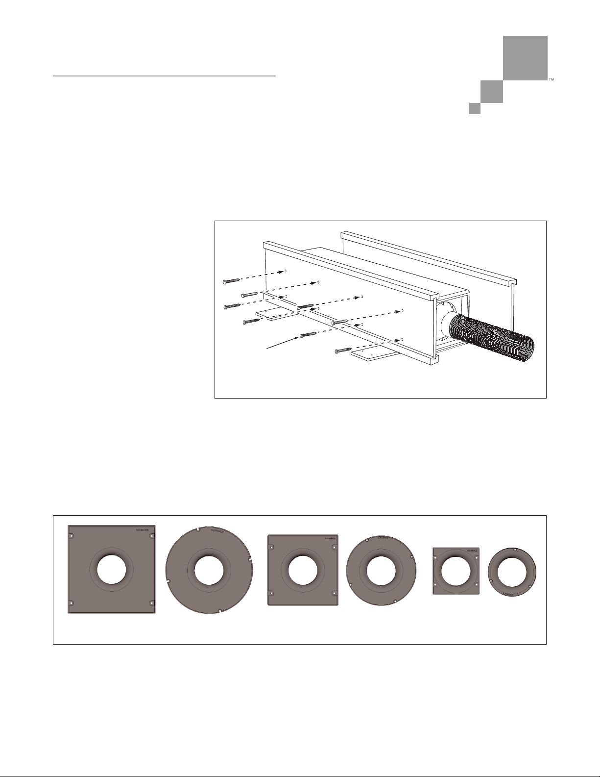
7. Screw the eight included lag
screws through the holes in
the joist and into the holes in
the side of the BPS-1 cabinet,
as shown in
Figure 5
. Use the
shorter lag screws for I-joist
construction; use the longer
lag screws for standard joist
construction.
8. After confirming that the
BPS-1 cabinet is securely
attached to the joist, remove
the temporary brackets from
the underside of the joists.
Selecting the Proper Adaptor Baffle
Sonance has BPS-1 Adaptor Baffles available that mate the BPS-1 to every size round and square
Architectural Series panel bracket. The Adaptor Baffles provide proper acoustic performance without
creating port noise or buzzing during operation.
Select the Adaptor Baffle that fits the particular size and shape Architectural Series Panel Bracket you
installed. BPC8R/S fit 8” Panel Brackets, BPC6R/S fit 6” Panel Brackets, BPS4R/S fit 4” Panel Brackets
(see
Figure 6
).
The Adaptor Baffles include Allen screws, an Allen wrench and Locktite.
Architectural Series
™
BPS-1 IN-CEILING SUBWOOFER
I NSTALLATION M ANUAL
5/16”
Lag Screws
Figure 5: Using the Included Lag Screws to Attach the BPS-1 to the Joist
Figure 6: BPS-1 Adaptor Baffles (left to right): BPC8S, BPC8R, BPC6S, BPC6R, BPC4S, BPC4R
Page 4

Architectural Series
™
BPS-1 IN-CEILING SUBWOOFER
I NSTALLATION M ANUAL
Connecting the Vent Tube and Adaptor Baffle
1. Use a Phillips screwdriver to remove the four screws that attach the paint shield to the Architectural
Series Panel Bracket (see
Figure 7)
.
2. Feed several inches of the Vent Tube through the Panel Bracket’s speaker opening (see
Figure 8
).
3. Fit the Vent Tube Clamp (included with the Adaptor Baffle) loosely around the vent tube (see
Figure 9
).
4. Insert the Adaptor Baffle’s neck into the Vent Tube opening (see
Figure 10
).
Insert Adaptor
Baffle Neck
Into Vent Tube
Fit Clamp
Onto
Vent Tube
Figure 9: Fit the Clamp Onto the Vent Tube
Figure 10: Fit the Adaptor Baffle Neck Into the Vent Tube
Page 4 of 8
B6R
Sonance Architectural Series
5/8”
DRYWALL
WWW.SONANCE.COM
800.582.7777
Remove
Screws
Figure 7: Remove Panel Bracket
Paint Shield
Figure 8: Pull End of Vent Tube
Through Opening in Panel Bracket
Page 5

Architectural Series
™
BPS-1 IN-CEILING SUBWOOFER
I NSTALLATION M ANUAL
5. Make sure the Vent Tube Clamp is positioned
around the neck of the Adaptor Baffle and tighten
the clamp to secure the Vent Tube around the neck
of the Adaptor Baffle.
6. After confirming that the Vent Tube is securely
fastened around the neck of the Adaptor Baffle,
push the Adaptor Baffle into the Panel Bracket
speaker opening.
7. Use the hardware included with the Adaptor
Baffle to attach it to the Panel Bracket (see
Figure 11
):
a) Apply a drop of Locktite to each hex screw.
b) Use the hex wrench included with the Adaptor
Baffle to hand-tighten the hex screws and
secure the Adaptor Baffle to the Panel Bracket.
NOTE : THE INCLUDED LOCKTITE IS REQUIRED TO
PREVENT THE HEX SCREWS FROM COMING LOOSE
DURING OPERATION
Speaker Connections
IMPORTANT: T
HE BPS-1 IS SPECIFICALLY DESIGNED
FOR USE WITH THE SONAMP A150 AMPLIFIER, WHICH
HAS LIMITER CIRCUITRY THAT PREVENTS THE BPS-1’S
WOOFER DRIVER FROM BEING DAMAGED BY AMPLIFIER
CLIPPING. USE OF ANY OTHER POWER AMPLIFIER WITH
THE BPS-1 COULD RESULT IN DAMAGE TO THE
WOOFER AND WILL VOID THE BPS-1’S WARRANTY.
1. Run the speaker wire from the A150 amplifier to
the BPS-1 cabinet.
N OTE : REFER TO THE A150 INSTRUCTION
MANUAL FOR INFORMATION ABOUT AMPLIFIER
CONNECTIONS.
2. Pass the speaker wire through the BPS-1’s built-
in wire tie, and route the wire’s end to the
speaker connector panel (see
Figure 12
).
1. Apply Locktite
to Screws
2. Tighten Screws
with
Hex Wrench
Figure 11: Attach the Adaptor Baffle to the Panel Bracket
VERY IMPORTANT
U
SE ONLY THE SUPPLIED HAND
-
HELD HEX WRENCH TO ATTACH THE ADAPTOR BAFFLE.
DO NOT USE AN ELECTRIC SCREWDRIVER OR DRILL.
NEVER
OVER-TIGHTEN THE ADAPTOR B AFFLE MOUNTING SCREWS. OVER-TIGHTENING THE SCREWS CAN
FRACTURE THE BRACKET ASSEMBLY. THIS TYPE OF DAMAGE IS NOT COVERED BY THE ARCHITECTURAL S ERIES
PANEL BRACKET WARRANTY.
Page 5 of 8
Figure 12: BPS-1 Wire Management
and Speaker Connection
Page 6

Page 6 of 8
Architectural Series
™
BPS-1 IN-CEILING SUBWOOFER
I NSTALLATION M ANUAL
3. Strip ¼” – ½” of insulation from each lead of the speaker wire.
Twist the strands or tin the exposed wire with solder to ensure
that there are no stray strands. (Stray strands that touch each
other can cause a short-circuit that can damage the amplifier.)
4. The speaker’s positive connector post is labeled with a red dot;
the negative post is labeled with a black dot (see
Figure 13
).
Push the top of each connector post down to open the connector
and insert the exposed wires into the holes in the posts. Doublecheck that you connected amplifier “+” to speaker “+” and
amplifier “–” to speaker “–”.
5. Once you have verified that the connections are correct, tighten
the wire tie to secure the speaker cable to the BPS-1 cabinet. This
will help prevent the speaker from being accidentally disconnected
in the future.
Installing the Architectural Finish Component
The Architectural Finish Component is installed after the
ceiling is drywalled, finished and painted.
N
OTE : F
OR PAINTING INFORMATION
, REFER TO THE
INSTRUCTION MANUAL INCLUDED WITH THEARCHITECTURAL
F
INISH C OMPONENT
.
1. The foam-tape covered rim on the back of the Finish
Component inserts into the groove around the outer edge
of the Adaptor Baffle. See
Figure 14
.
2. Insert about half of the Architectural Finish Component
rim into the groove on the Adaptor Baffle. Gently fit the
remaining half of the rim by working around the Baffle,
fitting the rim into the groove as you go.
N OTE : FOR A PROPER INSTALLATION THE F OAM TAPE
SHOULD FIT SECURELY AND CONSISTENTLY INTO THE
GROOVE IN THE B AFFLE WITHOUT BINDING. IF NECESSARY,
LIGHTLY LUBRICATE THE F OAM TAPE WITH WATER TO EASE
INSERTION.
Figure 14: Attaching the Architectural Finish
Component To The Adaptor Baffle
Insert Finish Component Rim
Into Groove Around Baffle
Figure 13: BPS-1 Connection Terminals
Page 7

Page 7 of 8
Architectural Series
™
BPS-1 IN-CEILING SUBWOOFER
I NSTALLATION M ANUAL
Installing the Woofer Cabinet: Retrofit
The BPS-1 can be retrofit installed into a ceiling that has an attic or adequate crawlspace above it.
Due to the variety of possible installation situations, it is not possible to recommend a single retrofit
installation procedure. However, in any retrofit situation you should observe the following points to
achieve a safe and noise-free installation:
• Before installing the BPS-1 in any retrofit situation: Review the section
Installing The BPS-1 Cabinet In
New Construction
on pages 2 – 3 to become familiar with the installation procedure for new
construction.
• Determine the location for the Architectural Series Panel Bracket and install it first (its location may
be influenced by the locations of other AS speakers in the room). Then establish the location for the
BPS-1 cabinet relative to the Panel Bracket. The vent end of the BPS-1 cabinet should be located 12"
from the center of the Panel Bracket's speaker opening (see
Figure 2
, on page 2).
• When temporarily placing the BPS-1 cabinet in the ceiling bay before attaching it to the joist, take care
to support it so that it does not break-through the ceiling material (The BPS-1 cabinet weighs 46 lbs.)
• Use the supplied drilling template to determine the locations of the mounting holes on the joist.
NOTE : MAKE SURE THE HOLES ARE HIGH ENOUGH ON THE JOIST SO THAT THE WOOFER CABINET WILL NOT
CONTACT THE CEILING MATERIAL. (CONTACT WITH THE CEILING MATERIAL CAN CAUSE BUZZING DURING
OPERATION.) THE ONLY CONTACT SHOULD BE BETWEEN THE CABINET’S GASKETED MOUNTING SURFACE AND
THE MOUNTING JOIST.
• Once the BPS-1 cabinet is attached to the joist, complete the installation by following the instructions in
the
Selecting The Proper Adaptor Baffle, Connecting The Vent Tube And Adaptor Baffle, Speaker
Connections
and
Installing The Architectural Finish Component
sections on pages 3 – 6.
Specifications
Woofer: 8" (203mm) Long-throw felted paper cone with a rubber surround
Frequency Response: 35Hz – 150Hz ±3dB
Dimensions (W x H x D): 9" x 11" x 50½" (229mm x 279mm x 1283mm) Note: Depth includes port tube
Shipping Weight: 46 lbs (20.9kg) each
Page 8

SONANCE • 212 Avenida Fabricante • San Clemente, CA 92672-7531 • USA
800.582.7777 or 949.492.7777 • FAX: 949.361.5151 • Technical Support: 800.582.0772
www.sonance.com
©2008 Sonance. All rights reserved.
Sonance and Architectural Series are trademarks or registered trademarks of Dana Innovations.
Due to continuous product improvement, all specifications are subject to change without notice.
For the latest Sonance product specification information visit our website: www.sonance.com
33-4751 03/08
Architectural Series Speaker Limited Lifetime Warranty Coverage
(U.S.A. Only)
Sonance warrants to the original retail purchaser only that this Sonance product will be free from defects in materials and
workmanship, provided the speaker was purchased from a Sonance Authorized Dealer.
Defective products must be shipped, together with proof of purchase, prepaid insured to the Authorized Sonance Dealer from
whom they were purchased, or to the Sonance factory at the address listed on this instruction manual. Freight collect shipments will be refused. It is preferable to ship this product in the original shipping container to lessen the chance of transit
damage. In any case, the risk or loss or damage in transit is to be borne by the purchaser. If upon examination at the factory or Authorized Sonance Dealer it is determined that the unit was defective in materials or workmanship at any time during
this warranty period, Sonance or the Authorized Sonance Dealer will, at its option, repair or replace this product at no additional charge, except as set forth below. If this model is no longer available and can not be repaired effectively, Sonance, at
is sole option, may replace the unit with a current model of equal or grater value. In some cases where a new model is substituted, a modification to the mounting surface may be required. If mounting surface modification is required, Sonance
assumes no responsibility or liability for such modification. All replaced parts and product become the property of Sonance.
Products replaced or repaired under this warranty will be returned to the original retail purchaser, within a reasonable time,
freight prepaid.
This Warranty does not include service or parts to repair damage caused by accident, disaster, misuse, abuse, negligence,
inadequate packing or shipping procedures, commercial use, voltage inputs in excess of the rated maximum of the unit, or
service, repair or modification of the product which has not been authorized or approved by Sonance. This Warranty also
excludes normal cosmetic deterioration caused by environmental conditions. This Warranty will be void if the Serial Number
on the product has been removed, tampered-with or defaced. This Warranty is in lieu of all other expressed warranties. If the
product is defective in materials or workmanship as warranted above, the purchaser’s sole remedy shall be repair or replacement as provided above. In no event will Sonance be liable for any incidental or consequential damages arising out of the
use or inability to use the product, even if Sonance or an Authorized Sonance Dealer has been advised of the possibility of
such damages, or for any claim by any other party.
Some states do not allow the exclusion or limitation of consequential damages, so the above limitation and exclusion may not
apply. All implied warranties on the product are limited to the duration of this expressed Warranty. Some states do not allow
limitation on the length of an implied warranty. If the original retail purchaser resides in such a state, this limitation does not
apply.
EXCLUSIONS
AND L
IMITATIONS
The warranty set forth above is in lieu of all other warranties, express or implied, of merchantability, fitness for a particular
purpose, or otherwise. The warranty is limited to Sonance products registered herein and specifically excludes any damage
to loudspeakers and other allied or associated equipment which may result for any reason from use with this product. Sonance
shall, in no event, be liable for incidental or consequential damages arising from any breach of this warranty or otherwise.
This warranty gives you specific legal rights, and you may have other rights which vary from state to state.
 Loading...