


INTRODUCTION
Thank you for purchasing the AL2 — AL2/S Automatic Source Selector. The AL2 and AL2/S automatically switch between two line-level stereo sources: a main source connected to the Input A jacks and a remote source connected to the Input B jacks.
When the AL2 senses a remote source signal present at the Input B jacks, that source signal is automatically switched-through to the output jacks. When the remote source signal is no longer present on Input B, after a short (installeradjustable) time delay the AL2 and AL2/S automatically switch the outputs to the main source connected to the Input A jacks.
The time it takes the AL2 and AL2/S to switch back to Input A from Input B can be adjusted to suit the different types of audio sources being used, or the preferences of the listeners. The sensitivity of the detection/switching circuitry is also adjustable to work with a variety of audio source equipment.
I N S T R U C T I O N M A N U A L
A L 2 a n d A L 2 / S I N D U S T R Y U P G R A D E AUTOMATIC SECONDARY SOURCE SELECTOR
AL2 and AL2/S NEW FEATURES
The AL2 and AL2/S incorporate several new features that improve their performance and installability:
•The AL2 operates on a single-output 12V DC power supply, and can also be powered directly by 12V sources in cars, boats or RV installations. The AL2 power inputs have reverse polarity protection.
•The AL2 features DC In and DC Out connections that allow multiple Industry Upgrade units to share a single power supply.
•The AL2 Control Out and AL2/S Control In connectors are removable quick-toggle RIA connectors.
•The AL2 and AL2/S chassis have recessed mounting holes that allow them to easily be wall-mounted using two screws.
•TheAL2andAL2/Schassis’arecompatiblewith3”TK-seriesSnapTrack® fromAugat.
APPLICATIONS |
Sonamp will revert to its Standby mode and no sound will be heard.When the |
|
|
When the iPod is paused or not docked and the CD changer is not playing, the |
|
Here are three examples of how the AL2 and AL2/S can be used in different |
system is playing, volume is controlled by the in-wall volume controls. |
|
system configurations: |
Combining Two Separate Systems (see Illustration 2) |
|
Basic Music System (see Illustration 1) |
||
Two separate systems in a home (such as the preamp/controller for a whole- |
||
A basic music system consisting of two music sources (such as an iPort™ |
||
home audio system and a master bedroom system with a small receiver) could |
||
docking station and a CD changer), an AL2, a Sonance Sonamp® 275 SE |
be connected to the AL2’s A and B inputs. |
|
amplifier and speakers with in-wall volume controls would offer automatic |
Connecting the AL2’s outputs to the Bus inputs of a multi-zone amplifier like |
|
selection of the source and automatic turn-on of the Sonamp (using its Auto- |
||
the Sonamp 875 SE creates an elegant selector for the two systems. |
||
On feature). |
||
|
||
With the CD changer connected to the AL2’s Input A and the iPort connected |
With the whole-home system preamp connected to the AL2’s Input A and the |
|
bedroom system’s Tape Monitor output connected to the AL2’s Input B, the |
||
to it’s Input B, the CD changer would be the system’s main source and would |
||
bedroom system is now the remote source. Whenever it presents a signal to |
||
remain automatically selected by the AL2 whenever the iPod® was paused, or |
||
the AL2 the whole-home system preamp is overridden and the bedroom |
||
was not docked in the iPort. When the iPort/iPod sends an audio signal to the |
||
system will be heard throughout the house. As with the first example, the |
||
AL2 it would automatically be selected and its signal sent to the amplifier. |
||
whole-home system’s in-wall volume controls would control the volume in |
||
|
||
A system like this does not require a preamp or other source selecting device. |
each individual zone. |
|
Illustration 1: Basic Music System |
Illustration 2: Combining Two Separate Systems |
iPort |
iPort |
Zone 1 |
Volume |
Bedroom |
Zone 1 |
Volume |
Speakers |
||||||
with |
Wallplate |
Speakers |
Control |
Bedroom |
Speakers |
Control |
iPod |
|
|
|
|
|
|
|
|
|
System |
|
|
|
|
CAT-5 |
|
|
Receiver |
|
|
|
Cable |
|
|
From |
|
|
|
|
|
|
Tape Record |
|
|
|
|
|
|
Outputs |
|
|
CD Changer |
|
Zone 2 |
Volume |
|
Zone 2 |
Volume |
|
|
Speakers |
Control |
Main System Preamp |
Speakers |
Control |
|
|
|
|
|
|
|
|
|
|
|
From |
|
|
|
|
|
|
Main |
|
|
|
|
|
|
Outputs |
|
|
Zone 3 |
Volume |
Zone 3 |
Volume |
Speakers |
Control |
Speakers |
Control |
|
|
|
|
|
275 SE |
|
|
|
|
|
|
875D SE |
|
|
|
|
|
|
|
|
|
+ |
– |
|
Amplifier |
|
INPUT A |
CONTROL OUTPUT |
INPUT B |
|
Amplifier |
|
|
|
|
|
|
|
|
|
|
|
|
|
|
|
|
+ |
– |
|
|
|
|
|
|
|
|
|
|
|
INPUT A |
CONTROL OUTPUT |
INPUT B |
|
|
|
12VDC 100mA |
|
|
|
|
|
|
|
|
|
|
||
|
|
12VDC 100mA |
|
|
|
|
|
|
|
|
|
|
|
|
|
|
|
|
|
|
|
|
|
|
|
|
|
|
|
AL2 |
|
1–2 |
|
3–4 |
|
5–6 |
|
7–8 |
|
|
|
L |
R |
AL2 |
|
|
L |
R |
L |
R |
L |
R |
L |
R |
L |
R |
|||
|
|
|
|
|
|
|
|
|
|
|
|
SONAMP 875D SE |
|
|
|
|
|
|
|
|
|
|
|
|
|
|
IN |
|
|
|
|
|
|
|
|
|
|
|
|
|
IN |
|
|
|
|
|
12VDC |
|
|
|
|
|
|
|
|
|
|
|
|
|
12VDC |
|
|
|
|
|
150mA |
|
|
|
|
|
|
|
|
|
|
|
|
|
150mA |
|
|
|
|
|
OUT |
|
|
TRIGGER |
B TO A |
|
|
|
|
|
|
|
|
|
|
|
|
|
AL2 |
|
|
SENSITIVITY |
DELAY |
|
|
|
|
|
|
|
|
||
|
OUT |
|
|
TRIGGER |
B TO A |
AUTO SWITCH, LINE LEVEL |
|
|
|
|
|
|
|
|
|
||||
AL2 |
|
|
SENSITIVITY |
DELAY |
|
To BUS Inputs |
|
|
|
|
|
|
|
||||||
AUTO SWITCH, LINE LEVEL |
|
|
|
|
|
|
|
|
|
|
|
|
|
||||||
|
|
|
|
|
Selector |
|
|
|
|
|
|
|
|
|
|
|
|
|
|
Selector |
|
|
|
|
|
|
|
|
|
|
|
|
|
|
|
|
|
|
|
1
I N S T R U C T I O N M A N U A L
A L 2 a n d A L 2 / S I N D U S T R Y U P G R A D E
AUTOMATIC SECONDARY SOURCE SELECTOR
In a Home Theater System (see Illustration 3)
The AL2 and AL2/S can be used to automatically select between a VCR and a cable TV tuner in a home theater system. The AL2 would switch the stereo audio signal feeding the surround sound receiver/processor, while the AL2/S would switch the composite video signal feeding the TV.
With the cable TV tuner connected to Input A and the VCR connected to Input B of the AL2 and AL2/S, the cable tuner would be the system’s main source and would remain automatically selected by the AL2 whenever the VCR was not playing. When the VCR sends an audio signal to the AL2 and a video signal to the AL2/S, it would automatically be selected and its signal sent to the surround receiver/processor and TV.
Illustration 3: Home Theater System
TV/Monitor |
Left Speaker |
Center Speaker |
Right Speaker |
|
From |
|
From |
Cable TV Tuner |
Composite |
VCR |
Composite |
Video Output |
Video Output |
From |
From |
L/R Audio |
|
Outputs |
L/R Audio |
|
Outputs |
 To Composite
Video Input
L |
R |
|
|
L |
R |
L |
R |
|
|
L |
R |
|
|
|
|
|
|
|
|
|
|
|
|
|
Surround Sound |
INPUT A |
12VDC 100mA |
INPUT B |
INPUT A |
12VDC 100mA |
INPUT B |
Receiver/Processor |
||||||
|
|
+ |
– |
|
|
|
|
+ |
– |
|
|
|
|
|
CONTROL OUTPUT |
|
|
|
|
CONTROL INPUT |
|
|
|
||
|
|
L |
R |
|
AL2 |
|
L |
R |
AL2/S |
|
||
|
IN |
|
|
|
|
|
|
|
|
|
|
|
|
12VDC |
OUTPUT |
|
|
|
|
OUTPUT |
|
|
|
||
|
150mA |
|
|
|
|
|
|
|
||||
|
OUT |
|
|
|
TRIGGER |
B TO A |
|
|
|
|
|
|
AL2 |
|
|
SENSITIVITY |
DELAY |
|
|
|
|
AL2/S |
|
||
AUTO SWITCH, LINE LEVEL |
|
|
SLAVE, LINE LEVEL |
|
||||||||
|
|
|
|
|
|
|
|
|
|
To Audio |
||
Selector |
|
|
|
|
|
|
|
|
|
|
Selector |
|
|
|
|
|
|
From Control Output |
|
|
|
|
Source Inputs |
||
|
|
|
|
|
|
To Control Input |
|
|
|
|
|
|
Powered Subwoofer
|
|
|
|
|
|
Left Surround |
|
|
Right Surround |
|
|
|
||
|
Speaker |
|
|
Speaker |
|
|
|
|
|
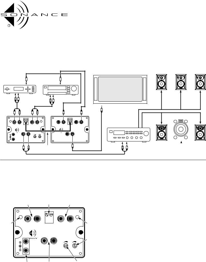
CONNECTING THE AL2 (see Illustration 4)
IMPORTANT: Make sure all source components and power amplifiers are turned OFF before making any connections.
Do not plug the AL2 power supply into a wall outlet until all connections have been made.
Illustration 4: AL2 Connections and Controls
Main |
Control |
Remote |
Input |
Output |
Input |
|
L |
R |
|
|
L |
R |
|
Input A |
|
|
|
|
|
|
Input B |
Active |
INPUT A |
+ |
– |
INPUT B |
Active |
||
Indicator |
CONTROL OUTPUT |
Indicator |
|||||
|
|
|
12VDC 100mA |
|
|
||
|
|
|
L |
R |
|
AL2 |
Switching |
|
|
|
|
|
|
|
|
|
|
|
|
|
|
|
Delay Time |
|
IN |
|
|
|
|
|
Adjustment |
|
12VDC |
|
OUTPUT |
|
|
|
|
|
150mA |
|
|
|
|
||
|
OUT |
|
|
|
|
B TO A |
|
|
|
|
|
SENSITIVITY DELAY |
|
||
|
AUTO SWITCH, LINE LEVEL |
|
|||||
|
Power |
|
Output |
|
Trigger |
|
|
|
Supply |
|
|
|
|
Sensitivity |
|
|
Connections |
|
|
|
|
Adjustment |
|
1.Determine which component will be the main (default) source and which is the remote (sensing/switching) source. In most cases the Main source will be the one with program that is continuous or active most of the time, such as a satellite radio or cable TV tuner, or a CD changer in the Continuous Repeat or Random Play mode. The Remote source will be something with program material the user will be watching or listening to for a relatively short time, such as a an iPort/iPod, CD player, or VCR.
2.Connect the left & right line outputs of the main source to the AL2’s Input A jacks; connect the left & right line outputs of the remote source to the AL2’s
Input B jacks.
3.Connect the AL2’s left & right Outputs to the inputs of the system’s amplifier, preamp/controller or receiver.
4.Connect the included PS-1 power supply to the AL2’s 12V DC jack and plug it into a non-switched AC outlet that supplies continuous current.
•If you’re using more than one Sonance Industry Upgrade component you can power it from the AL2’s power supply by connecting a cable with standard 2.1mm internal diameter connectors between the AL2’s Loop jack and the other component’s 12V DC jack.
5.The amount of time it takes for the AL2 to revert back to Input A after the signal to Input B has stopped is user-adjustable by the B To A Delay Adjust control. Turning the control clockwise increases the delay time.
•The minimum delay time is 3 seconds; the maximum is 3 minutes.
6.The amount of Input B voltage required to switch the AL2 from Input A to Input B is user-adjustable by the Trigger Sensitivity control. Turning the control clockwise increases the trigger sensitivity (requires less voltage to trigger the inputs to change).
• The minimum voltage required for triggering is 5mV; the maximum is 4.5V.
2
 Loading...