


875D SE

INSTRUCTION MANUAL
S
ONAMP
®
875D SE
8-C
HANNEL
A
MPLIFIER

3
IMPORTANT: Read all of these instructions before you
install or operate your 875D SE, and save these
instructions for later use.
11.. RReeaadd IInnssttrruuccttiioonnss
— All these safety and operating
instructions should be read before you operate the unit.
22.. RReett aaii nn II nnsstt rruucc tt iioo nnss
— These safety and operating
instructions should be retained for future reference.
33.. HHee ee dd WWaarr nnii nnggss
— All warnings on the unit and in the
operating instructions should be adhered to.
44.. FF oolllloo ww II nnsstt rruucc ttii oonn ss
— All operating and use instructions
should be followed.
55.. WWaatt ee rr aa nndd MMoo iisstt uu rr ee
— The unit should not be used
near water — for example, near a bathtub, washbowl,
kitchen sink, laundry tub, in a wet basement, or near a
swimming pool, and the like.
66.. CC aa rrttss aa nndd SStt aann dd ss
— The unit should
be used only with a cart or stand that is
recommended by the manufacturer.
• A unit and cart combination should be
moved with care. Quick stops, excessive
force, and uneven surfaces may cause
the unit and cart combination to overturn.
77.. CCAA UUTT IIOONN:: TToo pprr ee vveenn tt eellee ccttrr iicc sshh oocckk ,, dd oo nnoo tt uu ssee tthhee
aammppll iiffii ee rr ’’ss ppoo llaa rr iizzeedd ppll uugg wwii tthh aann eexxtteennssi
ioonn ccoorrdd,,
rreecceepptt aaccllee,, oorr ootthheerr oouuttlleett ss uu nnlleessss tthh ee bbllaaddeess ccaann bbee
ffuullll yy iinnsseerrtteedd ttoo pp rreevveenntt bbllaaddee eexxppoo s
suu rr ee ..
88.. VVee nnttii ll aatt iioo nn
— The unit should be situated so that its
location or position does not interfere with its proper
ventilation. For example, the unit should not be situated
on a bed, sofa, rug, or similar surface that may block
the ventilation openings; or be placed in a built-in
installation, such as a bookcase or cabinet, that may
impede the flow of air through the ventilation openings.
99.. HH eeaatt
— The unit should be situated away from heat
sources such as radiators, heat registers, stoves, or other
appliances (including other audio components) that
produce heat.
1100.. PP oo wweerr SS oouu rrcc ee ss
— The unit should be connected to a
power supply only of the type described in the operating
instructions or as marked on the unit.
1111.. GGrroouunn dd ii nngg oorr PPoo ll aa rrii zz aatt ii oo nn
— Precautions should be
taken so that the grounding or polarization means of the
unit is not defeated.
1122.. PP oo wweerr CCoo rr dd PPrr oott ee cctt ii oo nn
— Power supply cords should
be routed so that they are not likely to be walked on or
pinched by items placed upon or against them, paying
particular attention to cords at plugs, convenience receptacles, and the point where they exit from the controller.
1133.. CCll eeaa nn ii nngg
— The unit should be cleaned only as
recommended by the manufacturer.
1144.. NNoonn -- UU ssee PPeerr iioo dd ss
— The power cord of the unit should
be unplugged from the outlet when left unused for a long
period of time.
1155.. OObbjj ee cctt aa nndd LLii qq uu iidd EE nntt rryy
— Care should be taken so
that objects do not fall and liquids are not spilled into the
enclosure through openings.
1166.. DDaammaa gg ee RReeqq uuii rrii nngg SSeerr vv ii ccee
— The unit should be
serviced by qualified service personnel when:
a. The power-supply cord or the plug has been damaged; or
b. Objects have fallen or liquid has been spilled into the
unit; or
c. The unit has been exposed to rain; or
d. The unit does not appear to operate normally or exhibits
a marked change in performance; or
e. The unit has been dropped or the enclosure damaged.
1177.. SSeerrvviicciinngg
— The user should not attempt to service the unit
beyond that described in the operating instructions.
All other servicing should be referred to qualified service
personnel.
Important Safety Information
The lightning flash with arrowhead
symbol, within an equilateral
triangle, is intended to alert the
user to the presence of uninsulated
dangerous voltage within the
product’s enclosure that may be of
sufficient magnitude to constitute a
risk of electric shock to persons.
The exclamation point within
an equilateral triangle is
intended to alert the user to the
presence of important operating and maintenance
(servicing) instructions in the
literature accompanying the
appliance.
TO PREVENT FIRE OR SHOCK
HAZARD, DO NOT EXPOSE THIS APPLIANCE TO RAIN OR MOISTURE. THE
APPLIANCE WHALL NOT BE EXPOSED
TO DRIPPING OR SPLASHING. NO
OBJECTS FILLED WITH LIQUIDS SHALL
BE PLACED ON THE APPLIANCE.
TO REDUCE THE RISK OF ELECTRIC
SHOCK, DO NOT REMOVE COVER OR
BACK. NO USER-SERVICEABLE PARTS
INSIDE. REFER SERVICING TO AUTHORIZED SERVICE PERSONNEL.
CAUTION:
4
SONAMP®875D SE 8-CHANNEL AMPLIFIER
Introduction
Thank you for purchasing the Sonance Sonamp®875D SE power amplifier. The 875D SE will provide you with many years
of home entertainment enjoyment. This manual will teach you all about your new amplifier’s many innovative features and
will show you how to get the very best performance from your amplifier. Please read it thoroughly.
Design and Features
Power
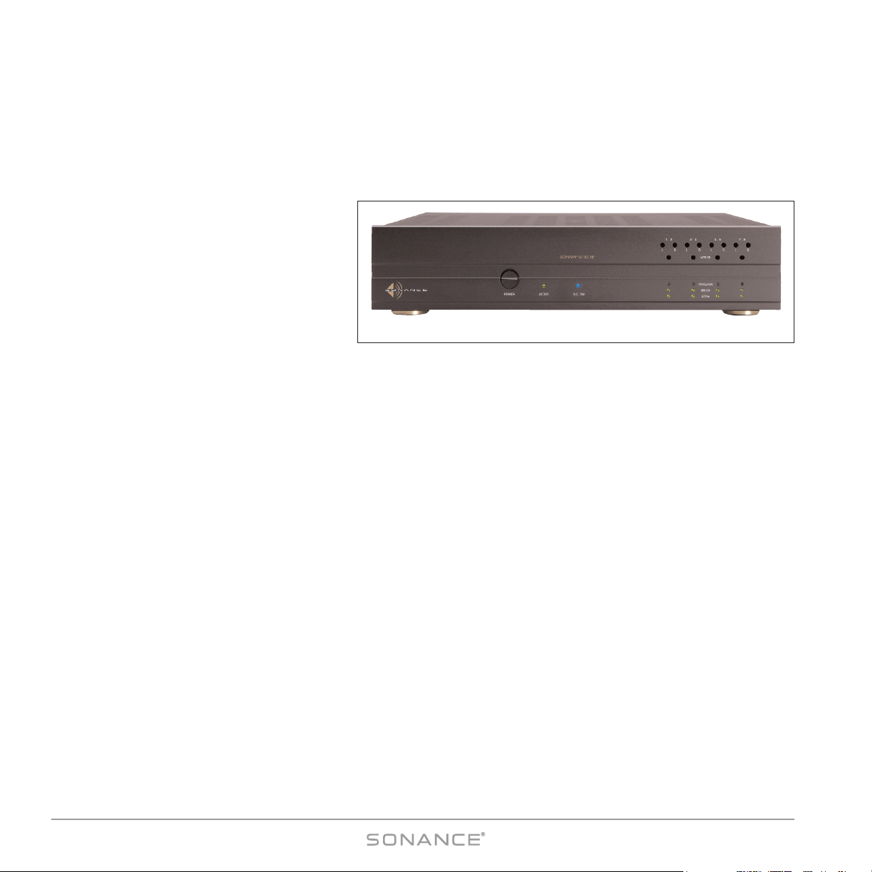
The Sonamp®875D SE is a hybrid amplifier that
combines digital amplification with analog
power supplies. Its Class T amplifier with Digital
Power Processing™ technology delivers the
high efficiency of digital (Class D) amplification
with the superior sound quality of analog (Class
AB) amplifiers. This allows the 875D SE to deliver high power (75 watts RMS per channel @ 8 ohms x 8 Channels) in an
exceptionally small (2U rack height) package. And unlike conventional digital amplifiers which cannot operate in bridged
configuration, the 875D SE’s Class T circuitry allows you to operate it with any of its four pairs of channels in a bridged
mode, providing 300 watts x 4 channels into an 8-ohm load. Four independent power supplies (one for each zone) supply
plenty of current, so each zone can maintain full performance regardless of how hard any other zones are being driven.
BBE®Sound Enhancement
The Sonamp 875D SE incorporates BBE®Sound Enhancement. The BBE process improves the presence and detail of speakers,
especially at lower listening volumes, improving the sound quality of your music — especially distributed audio systems
playing background music. BBE also restores clarity and definition (or focus) to spoken voices, which makes paging
systems easier to understand without having to run them at high volumes. Each zone in the 875D SE has individual
controls that let you set the BBE enhancement for that zone to +9dB, +6dB or OFF. The factory default setting is +6dB.
Inputs and Triggers
Multiple audio input connections (DIRECT, L/R & AUX) and buffered line outputs make your 875D SE extremely flexible, so
you can connect the amplifier in a variety of ways depending on your particular system’s configuration. The Illustrations on
pages 15 – 20 show the 875D SE being used in several different possible system configurations. Each zone has its own 12V
input and output triggers and defeatable auto-on signal sensing that can automatically turn the amplifier ON. Recessed
front-panel controls are tamper-resistant, and let you adjust each channel’s input level and each zone’s auto-on sensitivity.
Front-panel LEDs tell you if the 875D SE’s power is on or off, if each Zone is on or off, and the BBE status and fault status
for each zone.
Serial Control Capability
The 875D SE’s RS-232 connection lets you use a variety of 3rd-party serial control systems to control the amplifier.
The serial control provision lets you control almost all of the 875D SE’s functions, and also lets you monitor the amplifier’s
operation from a remote location.
Figure 1: Sonamp®875D SE
SONAMP®875D SE 8-CHANNEL AMPLIFIER
5
ON
ON
ON
ON
OFF
OFF
OFF
OFF
ON
ON
ON
ON
OFF
OFF
OFF
OFF
ON
ON
ON
ON
OFF
OFF
OFF
OFF
ON
ON
ON
ON
OFF
OFF
OFF
OFF
ON
ON
ON
ON
OFF
OFF
OFF
OFF
ON
ON
ON
ON
OFF
OFF
OFF
OFF
ON
ON
ON
ON
OFF
OFF
OFF
OFF
ON
ON
ON
ON
OFF
OFF
OFF
OFF
L
R
A
A.C. ON
AUTO ON
LRLRLRLR
1 – 2 3 – 4 5 – 6 7 – 8
PROTECTION
BBE ON
ACTIVE
ACTIVEPOWER
BBE CONTROL
BUS
INPUT
OUTPUT
BUFFERED
DIRECT
LEFT
RIGHT
AUX
DIRECT
LEFT
RIGHT
AUX
DIRECT
LEFT
RIGHT
AUX
DIRECT
LEFT
RIGHT
AUX
DIRECT
LEFT
RIGHT
AUX
AUTO
VOLT
AUTO
VOLT
AUTO
VOLT
AUTO
VOLT
TRIGGER MODE
DIRECT
LEFT
RIGHT
AUX
DIRECT
LEFT
RIGHT
AUX
DIRECT
LEFT
RIGHT
AUX
BBE CONTROL
INPUTS 5 – 24V AC–DC
EXTERNAL TRIGGER
INPUTS 5 – 24V AC–DC
TRIGGER OUTPUTS
12VDC
OFF
LOW
OFF
LOW
OFF
LOW
OFF
LOW
ON
HIGHONHIGHONHIGHONHIGH
1/2 3/4 5/6 7/8
+ 1 – – 2 + + 3 – – 4 + + 5 – – 6 + + 7 – – 8 +
CH
CH1 CH2
NORMAL BRIDGED NORMAL BRIDGED
ALL CH
CH
RS-232
1/2 3/4 5/6 7/8
CH 1/2
CH 3/4
CH 5/6
CH 7/8
OFF ON
ALL
S/N
1/2 3/4 5/6 7/8
+ – + – + – + – + –
BRIDGED
8Ω MIN
BRIDGED
8Ω MIN
BRIDGED
8Ω MIN
BRIDGED
8Ω MIN
NORMAL BRIDGED NORMAL BRIDGED
+ – + – + – + –
(BRIDGED)
CH3 CH4
(BRIDGED)
CH5 CH6
(BRIDGED)
CH7 CH8
(BRIDGED)
CAUTION: REPLACE WITH THE
SAME TYPE AND RATING FUSE
SONAMP® 875D SE
120V–60Hz 1200W
–FUSE T10AL 250V
RS-232
RS-232
RS-232
RS-232
1243
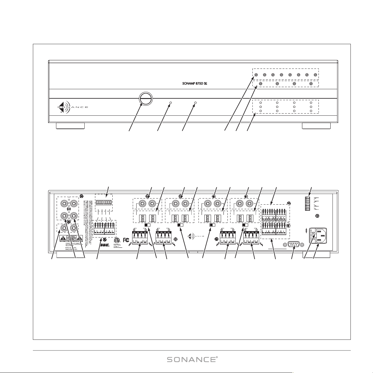
1. Power Button
2. Active LED
3. AC On LED
7. Aux Input & Buffered Output
8. Left & Right Bus Inputs
9. Left & Right Buffered Outputs
10. BBE External Control Input Connections
(Zones 1 – 4)
11. BBE Control Setting DIP Switches
(Zones 1 – 4)
12. Speaker Connectors (Zones 1 – 4)
13. Bridging Switches (Zones 1 – 4)
14. Direct Input Connections (Ch. 1 – 8)
15. Input Assignment DIP Switches (Ch. 1 – 8)
16. External Control Input Connections
(Zones 1 – 4 & ALL)
17. 12V Trigger Outputs (Zones 1 – 4 & ALL)
18. RS-232 Control Input
19. AC Fuse Holder
20. Power Cord Connection
21. Trigger Mode Switches (Zones 1 – 4)
4. Input Level Adjustments (Ch 1 – 8)
5. Auto-On Sensitivity Adjustments (Zones 1 – 4)
6. Protection, BBE On & Status Indicators (Zones 1 –4)
910
14
7 19 20
FRONT PANEL
REAR PANEL
5 6
15 15 15 1514 14 14 2116
138
11
12 12 13 13 13 12 1712 18
Figure 2: 875D SE Front and Rear Panels
6
SONAMP®875D SE 8-CHANNEL AMPLIFIER
Box Contents
Your Sonamp 875D SE box should contain the following items:
(1) Sonamp 875D SE amplifier
(2) Rack ears
(6) Removable control connectors — connected to the amplifier’s rear panel
(4) Removable speaker connectors — connected to the amplifier’s rear panel
(1) IEC Power cable
Unpacking
Save the shipping carton and polystyrene inserts so you can safely transport your amplifier in the future. Before you install
the amplifier, locate the serial number on the rear panel and note it here for future reference:
S/N: __________________
Placement
IIMMPPOORRTTAANNTT:: TToo aavvooiidd ddaammaaggee,, tthhee aammpplliiffiieerr mmuusstt aallwwaayyss rreesstt oonn iittss ffoouurr ffeeeett
ttoo aallllooww ssuuffffiicciieenntt
cclleeaarraannccee ffoorr pprrooppeerr vveennttiillaattiioonn..
Place the Sonamp 875D SE on a level surface, in an upright position, out of direct sunlight and away from windows
through which rain may enter.
Situate the amplifier away from heat sources such as hot air ducts or radiators. Be sure that the amplifier is adequately
ventilated by convection cooling or suitable cabinet fans.
IIMMPPOORRTTAANNTT :: TThhee 887755DD SSEE rreeqquuiirreess ffoouurr iinncchheess ooff cclleeaarraannccee oonn tthhee ttoopp aanndd aal
lll ssiiddeess..
• Never place any object on or against the amplifier.
• Never operate the amplifier on a carpeted surface as this will compromise ventilation.
• When the amplifier is installed in any cabinet, the front or back must be open during operation. Alternately, install fans
in the cabinet to assure continuous ventilation.
• When rack-mounting, use nylon washers on both sides of the ears to isolate the amplifier from the rack and prevent
ground loops and hum problems.
• Very sensitive low-level sources might pick up some hum radiated from the 875D SE’s power supply. If this occurs, move the unit
away from the other components.
7
SONAMP®875D SE 8-CHANNEL AMPLIFIER
Protection Circuits
Thermal Protection
If the amplifier’s cooling vents are blocked, or it is installed with inadequate ventilation the amplifier may
exceed its safe operating temperature. If the amplifier’s internal temperature exceeds 154°F (68°C) it
will self-protect, and the following will occur:
• The audio output to all connected zones will shut OFF.
• The front-panel P
ROTECTION LEDs (see
Figure 3
) will illuminate
yellow
.
• An over-temp message will be sent via RS-232.
Once a safe temperature (<67°C) is reached, the Protection LEDs will all extinguish. You can then
re-activate the amplifier, either by switching the front-panel Power button OFF and ON or by a ‘Power’
command if the amplifier is being serial controlled.
IIMMPPOORRTTAANNTT:: BBeeffoorree rree-aaccttiivvaattiinngg tthhee aammpplliiffiieerr,, ccoorrrreecctt tthhee pprroobblleemm tthhaatt ccaauusseedd tthhee
oovveerr-tteemmppeerraattuurree ccoonnddiittiioonn ((vvoolluummee sseett ttoooo hhiigghh,, iinnaaddeeqquuaattee vveennttiillaattiioonn,, eettcc..))
NOTE: If you’re serial-controlling the 875D SE you can poll the amplifier at any time and its internal
temperature will be reported to the control device.
Over-Current Protection
If an over-current condition occurs in a zone, that zone will shut OFF for 5 seconds and its PROTECTION LEDs will flash ON
and OFF. The zone will then turn back ON. If the over-current condition continues the zone will shut OFF for 6 seconds,
its P
ROTECTION LEDs will flash, then it will turn back ON. If the over-current condition continues this process will repeat,
with the wait time increasing by 1 second each time. When the wait time reaches 10 seconds the zone will LOCK, the
zone’s P
ROTECTION LEDs will continually illuminate and the amplifier must be powered OFF using the front-panel POWER
button (or a serial command, if the amp is being controlled via RS-232).
BB ee ff oorr ee ttuurrnn ii nngg tthh ee aa mm ppllii ffii ee rr OO NN aa gg aa ii nn,,
cc oorrrr ee cctt ww hhaa tteevv ee rr iiss cc aauu ss iinngg tthh ee oovv ee rr-- ccuu rrrr ee nntt cc oonn ddii tt iioo nn ii nn t
thh ee zz oonn ee ((ssppeeaa kk ee rr ii mmpp ee ddaann ccee ttoo oo lloo ww,, vvooll uummee ttoo oo
hh iigg hh,, ss hhoo rrtt -- cciirr ccuu iitt,, ee tt cc..))..
PROTECTION
BBE ON
ACTIVE
Figure 3:
F
RONT-PANEL
STATUS LEDs
8
SONAMP®875D SE 8-CHANNEL AMPLIFIER
Powering the Amplifier
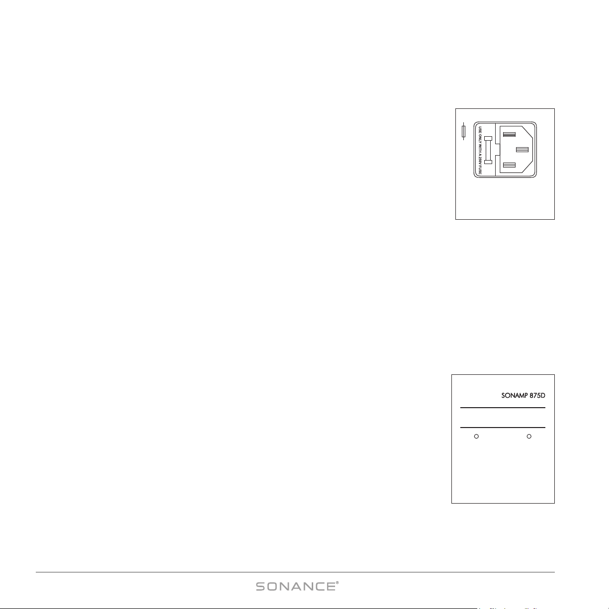
Power Cord (see Figure 4)
The Sonamp 875D SE features a removable IEC power cord. Plug the female end of the power
cord into the Power Cord Connector on the amplifier’s rear panel and plug the male end into a
20-amp grounded wall socket. DO NOT plug the power cord into an AC outlet on your
preamplifier/receiver.
CCAAUUTTIIOONN :: TToo pprreevveenntt eelleeccttrriicc sshhoocckk,, ddoo nnoott ddeeffeeaatt tthhee ggrroouunndd pprroonngg ooff tthhee
ppo
owweerr ccoorrdd pplluugg..
NOTE: If you need to use an extension cord, use only a heavy-duty (14-gauge or
larger) extension cord to avoid starving the amplifier of all the current
necessary for full-power operation.
Replacing the Fuse
(see Figure 4)
CCAAUUTTIIOONN:: FFoorr ccoonnttiinnuueedd pprrootteeccttiioonn aaggaaiinnsstt ffiirree,, rreeppllaaccee tthhee ffuussee wwiitthh oonnllyy tthhee
ssaammee ttyyppee aanndd rraattiinngg..
1. Remove the power cord from the wall outlet and from the amplifier’s Power Cord Connector.
2. Insert a flat-blade screwdriver or similar tool into the empty Power Cord Connector socket and gently pry the fuse holder out
of its socket.
3. Install the proper fuse in the fuse holder and replace the fuse holder back into its socket next to the power cord connection.
When the amplifier is operating, the fuse will blow to protect it from possible internal parts failure. NEVER replace the fuse
with any size other than that indicated on the rear panel to avoid more serious damage and the risk of fire. Substitution
of a larger fuse may create serious damage to internal parts and will void your Sonance warranty.
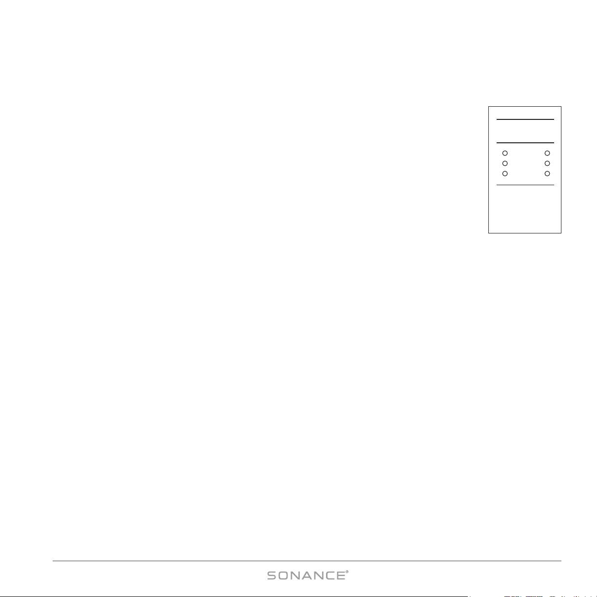
A.C. ON LED (see Figure 5)
The AC ON LED indicates that the amplifier’s power cord is plugged-into a live AC outlet and
its P
OWER button is ON. If the amplifier’s AC fuse ever opens, this LED will go out. To use the
A
UTO-ON feature (see page 12), this LED must remain ON at all times.
ACTIVE LED (see Figure 5)
The amplifier’s ACTIVE LED will illuminate whenever any zone is active. Each zone’s STATUS
INDICATORS (see
Figure 3
) also contain an ACTIVE LED that will illuminate whenever that particular
zone is ON.
A.C. ONACTIVE
Figure 5:
AC O
N and
A
CTIVE LEDs
CAUTION: REPLACE WITH THE
SAME TYPE AND RATING FUSE
120V–60Hz 1200W
–FUSE T10AL 250V
Figure 4:
Power Connector
and Fuse Holder
9
SONAMP®875D SE 8-CHANNEL AMPLIFIER
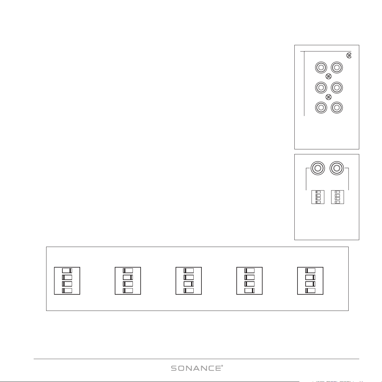
Source Connections (see
Figures 6 & 7
)
Always use quality high-fidelity interconnect cables such as Sonance MediaLinQ®Bronze
Interconnects. If source components are more than 20 feet from the amplifier, use the Sonance LS2
and LR2 Balanced Line-Level Sender and Receiver (sold separately) to avoid signal degradation.
NOTE: Always check local building codes before installing wire in walls or ceilings.
• Connect stereo source components (receiver, preamp, page signal, etc.) that will feed all 8
channels to the B
US
LEFT & RIGHT inputs (see
Figure 6
).
• Connect a mono auxiliary source (page signal, electronic doorbell, etc.) that will feed all 8
channels to the B
US
AUX input (see
Figure 6
).
• Connect zone-specific sources (audio control system zone output, video game, etc.) into the
individual channel D
IRECT inputs (see
Figure 7
).
• Connect additional amplifiers to the buffered
Bus Outputs
(see
Figure 6
). The source connect-
ed to the B
US LEFT & RIGHT Inputs appears at the L and R OUTPUTS, and the source connected
to the B
US AUX input appears at the AUX OUTPUT.
Input Assignment DIP Switches (see Figure 8)
The Sonamp 875D SE’s Input Assignment DIP switches provide the most flexible configuration
options of any multichannel amplifier. Settings are changed by setting the switches either OFF
(left) or ON (right):
DIRECT: Assign channel to the channel D
IRECT
input source.
LEFT: Assign channel to the Bus L
EFT input source (default for odd-numbered channels)
RIGHT: Assign channel to the Bus R
IGHT input source (default for even-numbered channels)
AUX: Assign channel to the Bus Aux input source
NOTE: All inputs selected by the DIP switches are summed-together. For example, for mono (L+R)
operation, activate both the Bus L and Bus R switches. Take care when setting volume levels, since
summed L&R inputs can increase signal gain by up to +6dB.
See pages 18 – 23 for illustrations of different system configurations.
ON
ON
ON
ON
OFF
OFF
OFF
OFF
ON
ON
ON
ON
OFF
OFF
OFF
OFF
DIRECT
LEFT
RIGHT
AUX
DIRECT
LEFT
RIGHT
AUX
CH1 CH2
(BRIDGED)
Figure 7:
Direct Inputs and
Input Assignment
DIP Switches
L
R
A
BUS
INPUT
OUTPUT
BUFFERED
Figure 6:
BUS Inputs &
Outputs; AUX Input
& Output
ON
ON
ON
ON
OFF
OFF
OFF
OFF
DIRECT
LEFT
RIGHT
AUX
ON
ON
ON
ON
OFF
OFF
OFF
OFF
DIRECT
LEFT
RIGHT
AUX
ON
ON
ON
ON
OFF
OFF
OFF
OFF
DIRECT
LEFT
RIGHT
AUX
ON
ON
ON
ON
OFF
OFF
OFF
OFF
DIRECT
LEFT
RIGHT
AUX
ON
ON
ON
ON
OFF
OFF
OFF
OFF
DIRECT
LEFT
RIGHT
AUX
DIRECT
INPUT
LEFT BUS
INPUT
RIGHT BUS
INPUT
AUX BUS
INPUT
MONO
OPERATION
Figure 8: Input Assignment DIP Switch Settings
 Loading...