

Page 1
INTRODUCTION
Thank you for purchasing the Sonance Smart Amplifier Technology® BBE® Sound Enhancement Module. This module can be used in any Sonamp® equipped
with our Smart Amplifier Technology (SAT).
BBE is a sound enhancement process used by hundreds of professional musicians and in recording studios and concert sound systems worldwide. Primarily
developed to compensate for the bass-through-treble timing errors that limit loudspeaker clarity and focus, the BBE process improves presence and detail of
speakers, especially at lower listening volumes. This makes it particularly effective at improving the sound quality of distributed audio systems playing background music. BBE restores clarity and definition (or focus) to spoken voices, making paging systems easier to understand without having to run them at high
volumes. The BBE process is so effective that it can even compensate for inferior sound from poor quality source material or compressed sources like MP3, etc.
For more information on the BBE process, go to www.bbesound.com.
INSTALLING THE BBE SAT MODULE IN AN AMPLIFIER
(See illustrations below)
Sonamps with Smart Amplifier Technology feature a rear-panel module bay. Replace the amplifier’s existing SAT module with the BBE SAT module.
IMPORTANT: Before installing the SAT module, make sure the amplifier’s power switch is OFF and its power cord is disconnected.
1
INSTRUCTION MANUAL
SMART AMPLIFIER TECHNOLOGY
®
BBE®SOUND ENHANCEMENT MODULE
1&7
2&6
3
&
5
1
&
7
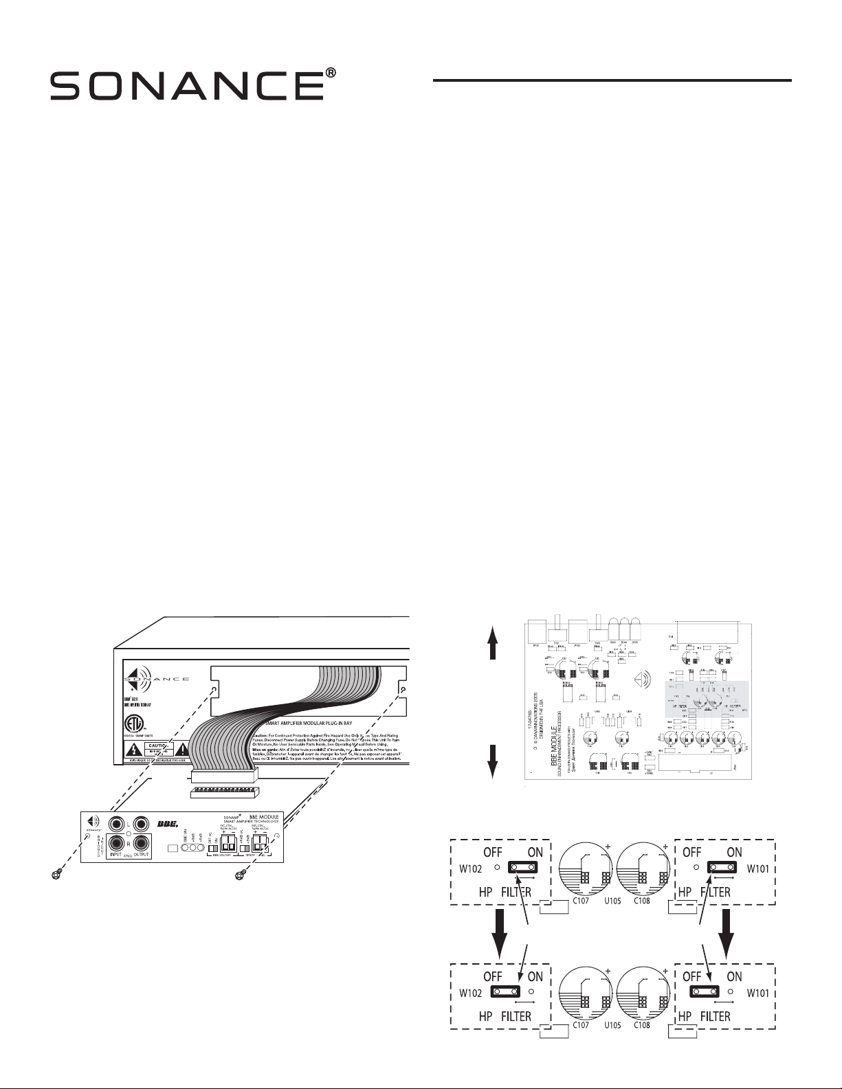
Replacing the SAT Module
TOWARDS
RIBBON
CONNECTOR
TOWARDS
INPUT/OUTPUT
CONNECTORS
Bypassing the Hi-Pass Filters on the BBE SAT Module
1. Remove and save the two screws holding the current SAT module in place.
2. Gently pull the existing SAT module out of the SAT module bay.
3. Flip the tabs on the ends of the ribbon connector socket outwards to release
it and disconnect the cable. (Note the alignment of the connector.)
4. Select the desired position of the high-pass filter jumpers on the BBE SAT
module.
Note: These jumpers are set at the factory in the high-pass filter
ON
position. Sonance
highly recommends
that these jumpers remain in
the
ON
position if the amplifier will be used in a system that includes
in-wall volume controls for the speakers.
If you wish to bypass the high-
pass filter, set the jumpers to the OFF position:
4a. The jumper pins are located in the shaded area of the illustration below.
4b. As shown in the illustration, remove the shorting sleeves from their
factory-set (ON) position on the jumper pins and replace them in the
OFF positions. Make sure you insert the shorting sleeves all the way
onto the jumper pins.
5. Re-connect the ribbon cable to the ribbon cable connector on the BBE SAT
module so that it clicks into place. Make sure the connector is aligned properly.
6. Slide the BBE SAT module into the SAT module bay.
7. Replace the two mounting screws.
HI-PASS FILTER ON
(FACTORY DEFAULT)
HI-PASS FILTER OFF
Jumper
Sleeve
Jumper
Sleeve
Page 2
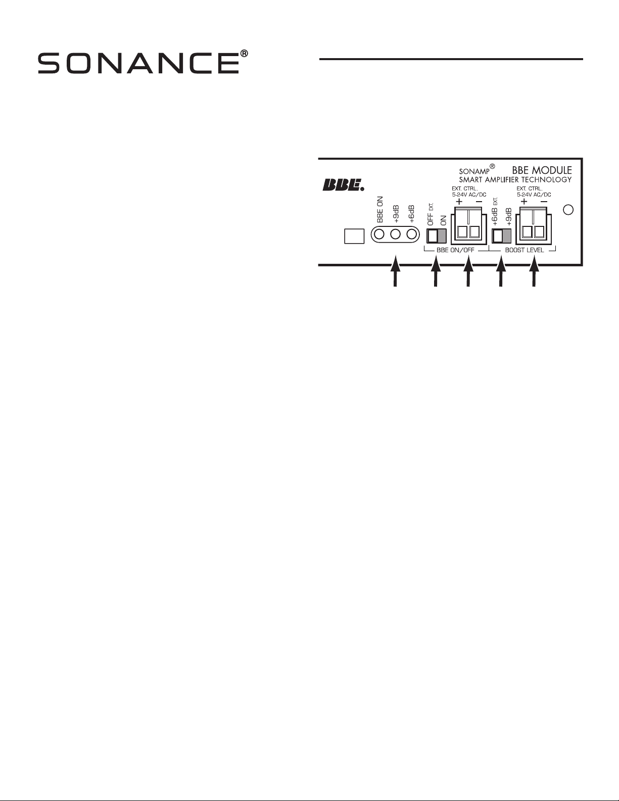
CONTROLS AND INDICATORS
(see illustration to the right)
1. Status LEDs: Illuminate to show if the BBE process is ON, and how
much processing (+6dB or +9dB) is being applied.
2. BBE ON/OFF switch: In the OFF
EXT. position, BBE processing is
bypassed; in the ON position BBE processing is applied.
• When this switch is in the OFF
EXT
. position BBE processing can be
automatically activated when an external control voltage is applied to
the BBE ON/OFF EXT. CTRL. connector.
3. BBE ON/OFF EXT. CTRL. connector: When a control voltage appears at this
connection and the BBE ON/OFF switch is in the OFF
EXT. position,
BBE processing is automatically activated.
• The connection accepts AC or DC control voltages between 5V and 24V.
4. BOOST LEVEL +6dB EXT./+9dB switch: Sets the amount of BBE processing
being applied to either +6dB or +9dB.
• When this switch is in the +6dB
EXT. position the amount of BBE processing being applied can be automatically changed to +9dB when an external control
voltage is applied to the BOOST LEVEL EXT. CTRL. connector.
5. BOOST LEVEL EXT. CTRL. connector: When a control voltage appears at this connection,and the BOOST LEVEL switch is in the +6dB
EXT. position,the amount
of BBE processing being applied is automatically changed to +9dB.
• The connection accepts AC or DC control voltages between 5V and 24V.
CONNECTIONS
(see illustrations on page 3)
Systems With No External Control Capability
1. Connect the BBE module’s Input jacks to the stereo line-level source.
• If you’re operating the Sonamp in the bridged mode, use the R input only.
2. Connect the Sonamp’s speaker outputs to the speakers.
3. If you wish to feed the source’s signal to additional amplifiers, connect them to the BBE module’s Output jacks.
Note: The signal sent through the module’s Output jacks is
not
BBE processed.
Systems With External Control Capability
The BBE sound enhancement process can be activated and the amount of BBE processing changed by an external control voltage. This allows an audio system
with two different sources to employ BBE processing for only one source, or to employ different amounts of BBE processing for the different sources.
The example on page 3 shows a system with two sources: a CD player playing uncompressed audio that doesn’t require BBE processing, and an iPod® playing
compressed audio files that could benefit from BBE enhancement. Both sources are connected to a Sonance AL1 Line-Level Switcher that automatically
switches to the iPod connections whenever it senses an audio signal from the iPod. Whenever AL1 selects the iPod input it also sends a +12V control voltage to
the BBE module’s BBE ON/OFF EXT. CTRL. connector, which activates the BBE processing.
When the AL1 no longer detects an audio signal from the iPod it automatically switches to the CD player input and removes the +12V control voltage.
When the control voltage is removed the BBE module switches the BBE processing off.
The BBE module has a second control voltage input (the BOOST LEVEL EXT. CTRL. connector) that operates in the same way, but changes the amount of BBE
processing from +6dB to +9dB. This connector can be employed when different amounts of BBE processing are desired for two different sources.
Note: The BBE module’s
External Control
inputs can also be triggered by voltage from a Crestron or similar control system.
1. Connect the BBE module’s Input jacks to the AL1 switcher’s Outputs.
• If you’re operating the Sonamp in the bridged mode, use the R input only.
2. Connect the outputs of the two sources to the AL1’s A and B inputs.
• Connect the source that you want BBE processed to the B inputs.
3. Connect the AL1’s Control Output to the BBE module’s BBE ON/OFF EXT. CTRL. input.
• Make sure that the module’s BBE ON/OFF switch is in the OFF
EXT. position.
4. Connect the Sonamp’s speaker outputs to the speakers.
5. If you wish to feed the AL1’s signal to additional amplifiers, connect them to the BBE module’s Output jacks. (The signal through the jacks is not BBE
processed).
• If the additional amplifiers are equipped with BBE module, run parallel control voltage connections to the other BBE modules.
2
INSTRUCTION MANUAL
SMART AMPLIFIER TECHNOLOGY
®
BBE®SOUND ENHANCEMENT MODULE
12345
Page 3

3
INSTRUCTION MANUAL
SMART AMPLIFIER TECHNOLOGY
®
BBE®SOUND ENHANCEMENT MODULE
B
R
I
D
G
E
D
I
N
/
O
U
T
Sonamp with
BBE SAT Module
Line-Level Stereo Source Component
(CD player, satellite radio tuner, etc.)
LINE OUT
L
R
Optional Second Zone
Amplifier and Speakers
* Buffered output signal is not BBE-processed
Sonamp with
BBE SAT Module
AL1
Automatic
Source
Selector
iPort
Wallplate
CD Player
LINE OUT
L
R
Cat5 Wire
*A trigger voltage can also be generated
by a control system such as a Crestron
or AMX
AL1
12VDC
Control
Output*
iPort
with
iPod
Connections in a System with No External Control Capability
Connections in a System with External Control Capability
(When the iPod is played the BBE processing will automatically be
engaged by the AL1 control voltage trigger.)
Page 4

Sonance • 212 Avenida Fabricante • San Clemente, CA 92672-7531, USA • (800) 582-7777 or (949) 492-7777 • FAX: (949) 361-5151 • Technical Support: (800) 582-0772
www.sonance.com
33-3864 07/05
©2005 Sonance. All rights reserved.
Sonance and Sonamp are registered trademarks of Dana Innovations, Inc.“BBE” and its designs are the registered trademarks of BBE Sound, Inc.
iPod is a registered trademark of Apple Computer, Inc.
INSTRUCTION MANUAL
SMART AMPLIFIER TECHNOLOGY
®
BBE®SOUND ENHANCEMENT MODULE
TECHNICAL ASSISTANCE AND SERVICE
If you any have questions about the operation or installation of this
product, please call our Technical Assistance Department on any business day at (800) 582-0772 or (949) 492-7777; from 7 a.m. to 5 p.m.,
Pacific Time.
If your product should need repair or service, contact your Sonance
Authorized Dealer for help, or use the following procedure:
1. Prior to calling Sonance, note the product’s model number, serial number, purchase date, and the name and address of the dealer where you
purchased the product.
2. Contact our Technical Assistance Department at the above
number(s) and describe the problem the unit is experiencing. If they
determine that the product requires service, they will transfer you to
our Customer Service Department, who will issue you a Return
Authorization (RA) Number.
IMPORTANT: YOU MUST HAVE PRIOR AUTHORIZATION TO
RETURN YOUR PRODUCT TO SONANCE!
3. If you’re directed to return the unit to Sonance for repair, pack the unit
in its original shipping carton. If needed, you can obtain replacement
packaging from us for a small charge. Note: it is best if you place the
box into an additional outer “overcarton”before shipment to minimize
a chance of theft in shipment. Please include a copy of the original bill
of sale inside the package.
4. Contact a package delivery service such as United Parcel Service or
Federal Express to arrange prepaid (not collect) shipping. Do not use
the U.S. Postal Service.
IMPORTANT: FREIGHT COLLECT SHIPMENTS WILL BE REFUSED.
5. Write the RA Number on the outside of the shipping carton.
6. Ship the packaged unit to:
Quality Assurance Department
Sonance
212 Avenida Fabricante
San Clemente, CA 92672-7531
LIMITED WARRANTY COVERAGE (U.S. ONLY)
Sonance warrants to the original retail purchaser only that this
Sonance product will be free from defects in materials and workmanship for a period of five (5) years, provided the product was purchased
from a Sonance Authorized Dealer.
Defective products must be shipped, together with proof of
purchase, prepaid insured to the Authorized Sonance Dealer
from whom they were purchased, or to the Sonance factory at the address
listed on this instruction manual. Freight collect shipments will
be refused. It is preferable to ship this product in the original shipping
container to lessen the chance of transit damage. In any case, the risk or
loss or damage in transit is to be borne by the purchaser. If, upon
examination at the factory or Authorized Sonance Dealer, it is
determined that the unit was defective in materials or workmanship at
any time during this warranty period, Sonance or the Authorized
Sonance Dealer will, at its option, repair or replace this product at no
additional charge, except as set forth below. If this model is no longer
available and can not be repaired effectively, Sonance, at is sole option,
may replace the unit with a current model of equal or grater value. In
some cases where a new model is substituted, a modification to the
mounting surface may be required. If mounting surface modification is
required, Sonance assumes no responsibility or liability for such modification. All replaced parts and product become the property of Sonance.
Products replaced or repaired under this warranty will be returned to the
original retail purchaser, within a reasonable time, freight prepaid.
This Warranty does not include service or parts to repair damage caused
by accident, disaster, misuse, abuse, negligence, inadequate packing or
shipping procedures, commercial use, voltage inputs in excess of the
rated maximum of the unit, or service, repair or modification of the
product which has not been authorized or approved by Sonance. This
Warranty also excludes normal cosmetic deterioration caused by
environmental conditions. This Warranty will be void if the Serial
Number on the product has been removed, tampered-with or defaced.
This Warranty is in lieu of all other expressed warranties. If the product
is defective in materials or workmanship as warranted above, the
purchaser’s sole remedy shall be repair or replacement as provided above.
In no event will Sonance be liable for any incidental or consequential
damages arising out of the use or inability to use the product, even
if Sonance or a Authorized Sonance Dealer has been advised of the
possibility of such damages, or for any claim by any other party.
Some states do not allow the exclusion or limitation of consequential
damages, so the above limitation and exclusion may not apply.All implied
warranties on the product are limited to the duration of this expressed
Warranty. Some states do not allow limitation on the length of an implied
warranty. If the original retail purchaser resides in such a state, this
limitation does not apply.
EXCLUSIONS AND LIMITATIONS
The warranty set forth above is in lieu of all other warranties, express or
implied, of merchantability, fitness for a particular purpose, or otherwise.
The warranty is limited to Sonance products registered herein and
specifically excludes any damage to loudspeakers and other allied or
associated equipment which may result for any reason from use with this
product. Sonance shall, in no event, be liable for incidental or consequential
damages arising from any breach of this warranty or otherwise. This
warranty gives you specific legal rights, and you may have other rights
which vary from state to state.
 Loading...