

Page 1

SONAMP
®
ASAP3D SE
S
TEREO POWER AMPLIFIER
INSTRUCTION MANUAL
Page 2
SONAMP®ASAP3D SE STEREO POWER AMPLIFIER
2
Important Safety Instructions
Basic safety precautions should always be followed when
using your ASAP3D SE amplifier, to reduce risk of fire,
electric shock, and injury to persons:
1. Read and understand all instructions.
2. Retain these instructions for future reference.
3. Follow all warnings and instructions in this manual and
marked on the product.
4. Any service or repair required must be performed by
qualified factory-authorized personnel.
5. Do not use the amplifier in a high-humidity environment or
near water — for example in a wet basement, or near a
wet bar or swimming pool.
6. Always provide adequate ventilation for the amplifier.
Allow a minimum of two (2) inches on all sides of the
amplifier. Do not block the cooling vents on the amplifier
case.
7. The amplifier should be situated away from heat sources
such as heat registers, radiators, stoves, or other
appliances that produce heat.
8. The amplifier should only be connected to a power supply
of the type marked on its back panel. The power supply
cord should be routed to avoid damage from contact with
sharp objects or being stepped on.
9. Unplug the amplifier during thunderstorms or when it will
be unused for extended periods of time.
10. Exercise care to avoid spilling liquids on or in the amplifier.
11. Do not place the amplifier on an
unstable table, stand, or cart.
Improper placement of the
amplifier may cause it to fall on
an adult or child causing serious
injury, as well as damage to the
amplifier.
12. Do not expose the amplifier to
dripping or splashing. Do not place objects filled with
liquids, such as vases, on the amplifier.
13. Cleaning: To clean the amplifier, wipe it with a soft cloth.
Do not use solvents, as they may damage the amplifier.
14. Non-Use Periods: Unplug the amplifier’s power cord from
the electrical outlet when the amplifier will be unused for
a long period of time.
15. Damage Requiring Service: The amplifier should be
serviced by qualified service personnel when:
A. The power cord or plug has been damaged
B. Objects have fallen, or liquids have been spilled into
the amplifier
C. The amplifier has been exposed to rain.
D. The amplifier does not appear to be operating properly
or exhibits a marked change in performance.
E. The amplifier has been dropped or appears to have
been damaged.
16. Servicing: The user should not attempt to service the
amplifier beyond that described in these instructions. All
other servicing should be referred to qualified service
personnel.
17. Storms: To prevent damage to components, unplug all
electronic equipment during thunderstorms.
Page 3
3
SONAMP®ASAP3D SE STEREO POWER AMPLIFIER
Introduction
Thank you for purchasing the Sonance ASAP3D SE amplifier.
When properly installed, this amplifier will give you many
years of entertainment pleasure. To get the most out of your
new amplifier, please read this manual thoroughly before you
begin installation.
To achieve the best performance, Sonance recommends that
this amplifier be installed by a Sonance Authorized
Dealer/Installer.
Design and Features
Automatic House/Local Source Switching
The ASAP3D SE will automatically switch a pair of speakers
between two different input sources. Typically, the
House
source will be a whole-home audio system that normally
plays in the area, and the
Local
source will be a nearby
source, such as a TV set. The ASAP3D SE can be set up so
that any one of several different triggers will cause it to automatically switch from the House source to the Local source.
A typical application would be to use the ASAP3D SE to
power and automatically switch a pair of speakers in a
bedroom from playing background music sent by a wholehome audio system to playing the sound of the bedroom TV
whenever the TV is switched ON. With the amplifier’s Mono
Variable Output feeding a local-zone powered subwoofer,
this installation would provide much better sound quality
than the TV could supply on its own.
Flexible Triggering
Switching from the House to the Local source can be
triggered in four different ways:
• By the presence of an audio signal at the L
OCAL LINE inputs
or L
OCAL SPEAKER inputs;
• When a TV set that is connected to the ASAP3D SE’s AC
Outlet is turned ON;
• By an external control voltage connected to the V
OLTAGE
T
RIGGER input;
• By an IR controller connected to the IR Input.
IR Control
The ASAP3D SE has IR Input connections that allow its
automatic input switching, volume, muting and BBE to be
controlled by an IR keypad controller. IR Output connections
allow the connection of Sonance OptiLinQ
®
IR emitters so that
3rd-party control signals can be passed-through to their
intended components, and an IR Bus connection allows IR
signals from multiple ASAP3D SEs to be passed-through to a
single set of IR emitters.
BBE®Sound Enhancement
The ASAP3D SE incorporates BBE®Sound Enhancement. The
BBE process improves the presence and detail of speakers,
especially at lower listening volumes, so distributed audio
systems playing background music sound better at quiet
volume levels. BBE also restores clarity and definition
(or focus) to spoken voices, making paging systems easier to
understand without having to run them at high volumes.
The ASAP3D SE has controls that let you set the BBE
enhancement to HI, LOW or OFF.
Digital Amplification
The ASAP3D SE utilizes a highly-efficient ICEpower®digital
amplifier that provides 50 watts RMS per channel in stereo.
The ICEpower’s high efficiency produces high power in a 1U
high/½ rack width package, with very little heat generation.
This expands installation options, improves long-term
reliability and provides significant energy savings over
conventional amplifier designs.
Box Contents
Your ASAP3D SE amplifier box should contain the following:
(1) ASAP3D SE Power amplifier
(1) Joining Plate
(4) Rack-mount screws and (4) nylon washers
(1) IEC Power cord (120V version only)
(1) AC Trigger Outlet cable (120V version only)
(4) Stick-on rubber feet
Unpacking
Save the shipping carton and polystyrene inserts so you can
safely transport your amplifier in the future. Before you install
the amplifier, locate the serial number on its rear panel and
note it here for future reference:
S/N:
ASAP3D SE STEREO POWER AMPLIFIER
Page 4
SONAMP®ASAP3D SE STEREO POWER AMPLIFIER
4
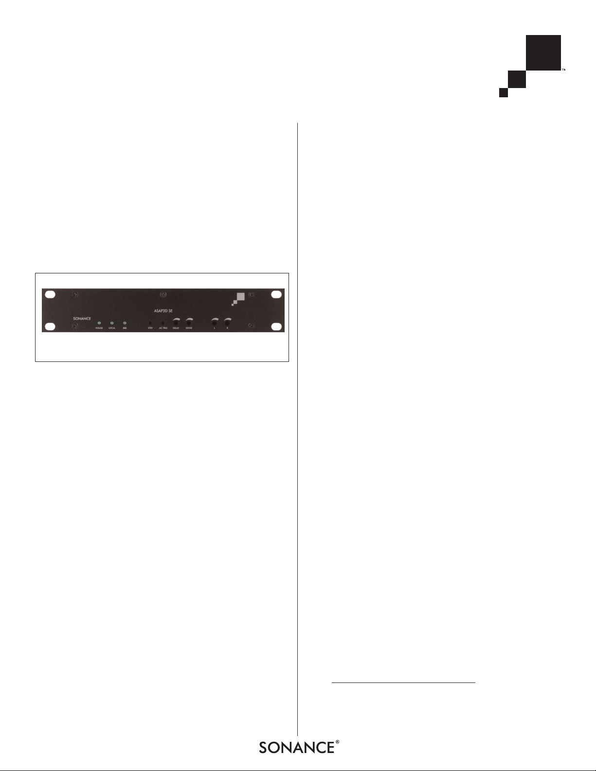
Placement/Installation
The Sonamp ASAP3D SE is designed to operate automatically
and is housed in a compact chassis that can be conveniently
mounted out of sight. The amplifier can be placed
horizontally on the supplied rubber feet, or it can be hung on
a wall — hidden behind a wall-mounted flat-panel TV — using
the keyhole-shaped hole on its bottom panel.
The ASAP3D SE includes a joining plate that allows it to be
rack-mounted in a single 1U space side-by-side with another
ASAP3D SE. An optional Rack-Mount Filler Panel is available
(Sonance part #92729) that allows a single ASAP3D SE to be
mounted in a 1U rack space.
Stand-Alone Placement
I
MPORTANT: T
O AVOID DAMAGE, THE AMPLIFIER MUST
ALWAYS REST ON ITS FOUR FEET TO ALLOW SUFFICIENT
CLEARANCE FOR PROPER VENTILATION.
Apply the four supplied stick-on feet to the amplifier’s bottom
panel and place the ASAP3D SE on a level surface, in an
upright position, out of direct sunlight and away from
windows through which rain may enter.
Situate the amplifier away from heat sources such as hot air
ducts or radiators. Be sure that the amplifier is adequately
ventilated by convection cooling or suitable cabinet fans.
When using the ASAP3D SE with a TV set, it may be
convenient to hide the amplifier inside of the TV cabinet or
bookshelf (but not on the TV itself).
IMPORTANT: THE ASAP3D SE REQUIRES TWO INCHES OF
CLEARANCE ON THE TOP AND ALL SIDES.
• Never place any object on or against the amplifier
• Never operate the amplifier on a carpeted surface, as this
will compromise ventilation.
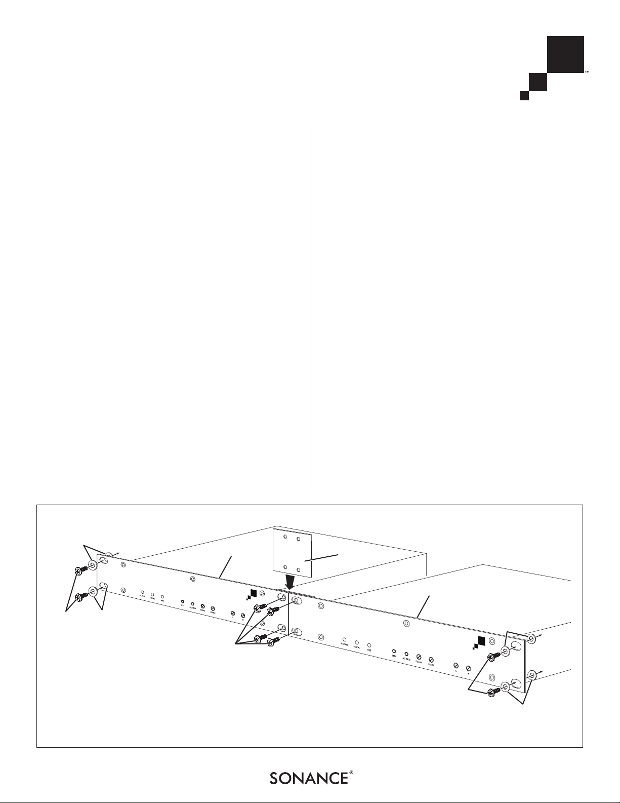
Rack-Mounting
Two ASAP3D SE amplifiers can be rack-mounted side-by-side
using the included joining plate.
• If they’ve already been installed, remove the amplifier’s
stick-on feet before using the included rack-mount
accessories.
• Use nylon washers on rack-mount screws to isolate the
amplifiers from the rack rails (see
Figure 1
). This will help
prevent ground loops and hum problems.
• Very sensitive low-level components might pick up some
hum radiated from the ASAP3D SE’s power supply. If this
occurs, move the amplifier to another rack position, away
from the other components.
To rack-mount the ASAP3D SE (see Figure 1):
1. Place the amplifier with its front panel touching the
other amplifier or rack-mount filler panel.
2. Slip the Joining Plate behind the rack holes and attach
it using 4 rack screws.
3. Attach the assembled unit to the rack using 4 more
rack screws. Use nylon washers on the rack screws in
front of and behind the face plates to isolate them from
the rack rails, to help prevent ground loops and hum.
Joining
Plate
ASAP3D SE
ASAP3D SE
To Rack
Rail
To Rack
Rail
To Rack Rail
Rack-Mount
Screws
Rack-Mount
Screws
Rack-Mount
Screws
Nylon
Washers
Nylon
Washers
Nylon
Washers
Nylon
Washers
FIGURE 1: RACK-MOUNTING THE ASAP3D SE
Page 5
Powering the Amplifier
Power Cord Connection
The ASAP3D SE features an IEC power
connector (see
Figure 3
). Plug the
female end of the power cord into the
Power Cord Connector on the amplifier’s rear panel and plug the male end
into a grounded wall socket. Do NOT
plug the amplifier’s power cord into a
convenience outlet on any other audio
or video component. (Note: A power
cord is included only with the 120V
version of the amplifier.)
I
MPORTANT: DO NOT PLUG THE
POWER CORD INTO THE WALL OUTLET
UNTIL ALL SYSTEM CONNECTIONS HAVE BEEN MADE AND
VERIFIED.
N
OTE: IF YOU NEED TO USE AN EXTENSION CORD, USE ONLY A
HEAVY
-DUTY (16-GAUGE OR LARGER) EXTENSION CORD TO AVOID
STARVING THE AMPLIFIER OF ALL THE CURRENT NECESSARY FOR
FULL
-POWER OPERATION.
A.C. Fuse Holder
120V versions of the Sonamp ASAP3D
SE are shipped with a 2 amp AC fuse
installed. 230V versions have a 1.25
amp AC fuse installed. The fuse protects
the amplifier circuitry;
THE AC TRIGGER
OUTLET IS NOT PROTECTED BY THE FUSE.
To replace the fuse, unplug the power
cord from the Power Cord Connector
and use a screwdriver to remove the
fuse holder (see
Figure 4
).
CAUTION: FOR CONTINUED PROTECTION AGAINST
FIRE, REPLACE THE FUSE WITH ONLY THE SAME TYPE AND
RATING.
SONAMP®ASAP3D SE STEREO POWER AMPLIFIER
5
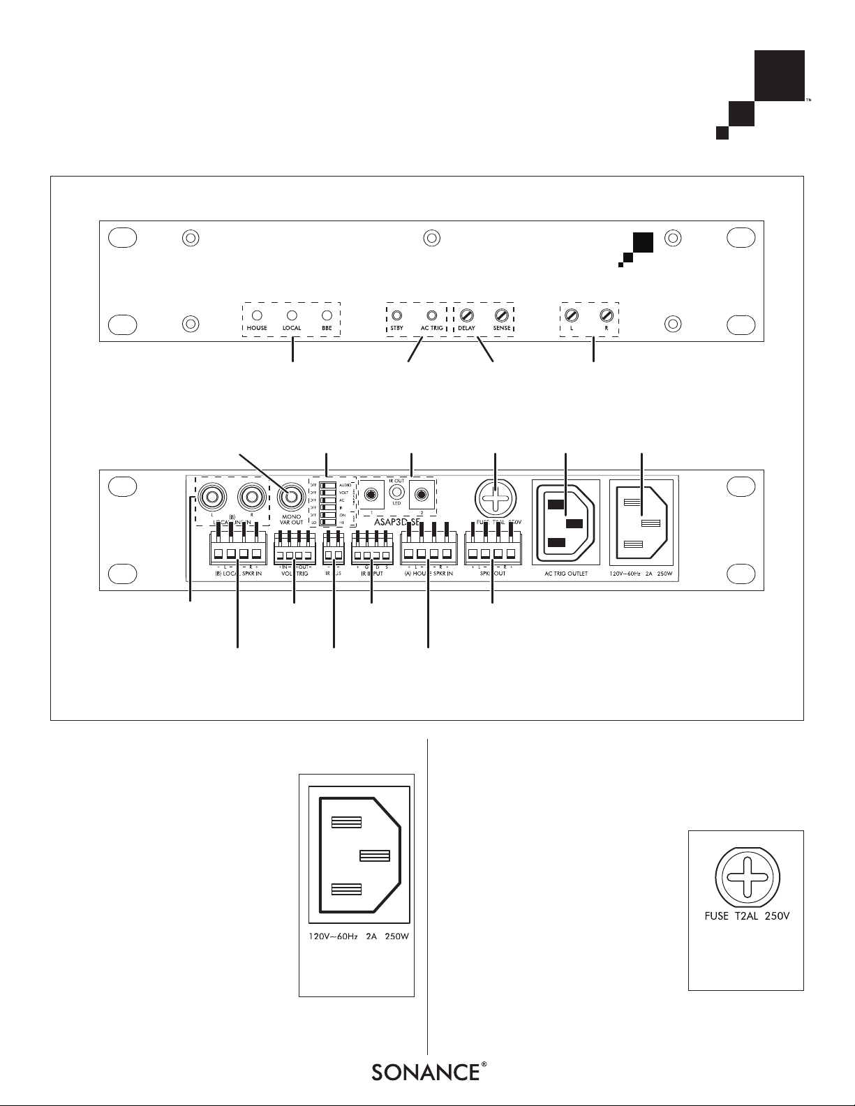
F
RONT PANEL
Status
LEDs
Local Source
Speaker-Level
Inputs
Voltage
Trigger
Connections
IR Bus
Connections
House
Speaker Input
Connections
IR Input
Connections
Speaker Output
Connections
Local Source
Line-Level
Inputs
Mono
Fixed/Variable
Output
Trigger and BBE
Mode Switches
IR Pass-Thru
Outputs
AC Fuse
Holder
Power Cord
Connection
AC
Trigger
Outlet
Standby and
AC Trigger
Pinhole Switches
R
EAR PANEL
Input
Level Controls
Switching Delay and
Trigger Level Sense
Adjustments
FIGURE 2: ASAP3D SE FRONT AND REAR PANELS
FIGURE 3:
P
OWER CORD
C
ONNECTION
FIGURE 4:
A.C. F
USE
HOLDER
Page 6
SONAMP®ASAP3D SE STEREO POWER AMPLIFIER
6
Audio Input Connections
IMPORTANT
: ALWAYS UNPLUG THE AMPLIFIER
’S POWER
CORD FROM THE WALL OUTLET BEFORE MAKING AUDIO
,
CONTROL OR SPEAKER CONNECTIONS
.
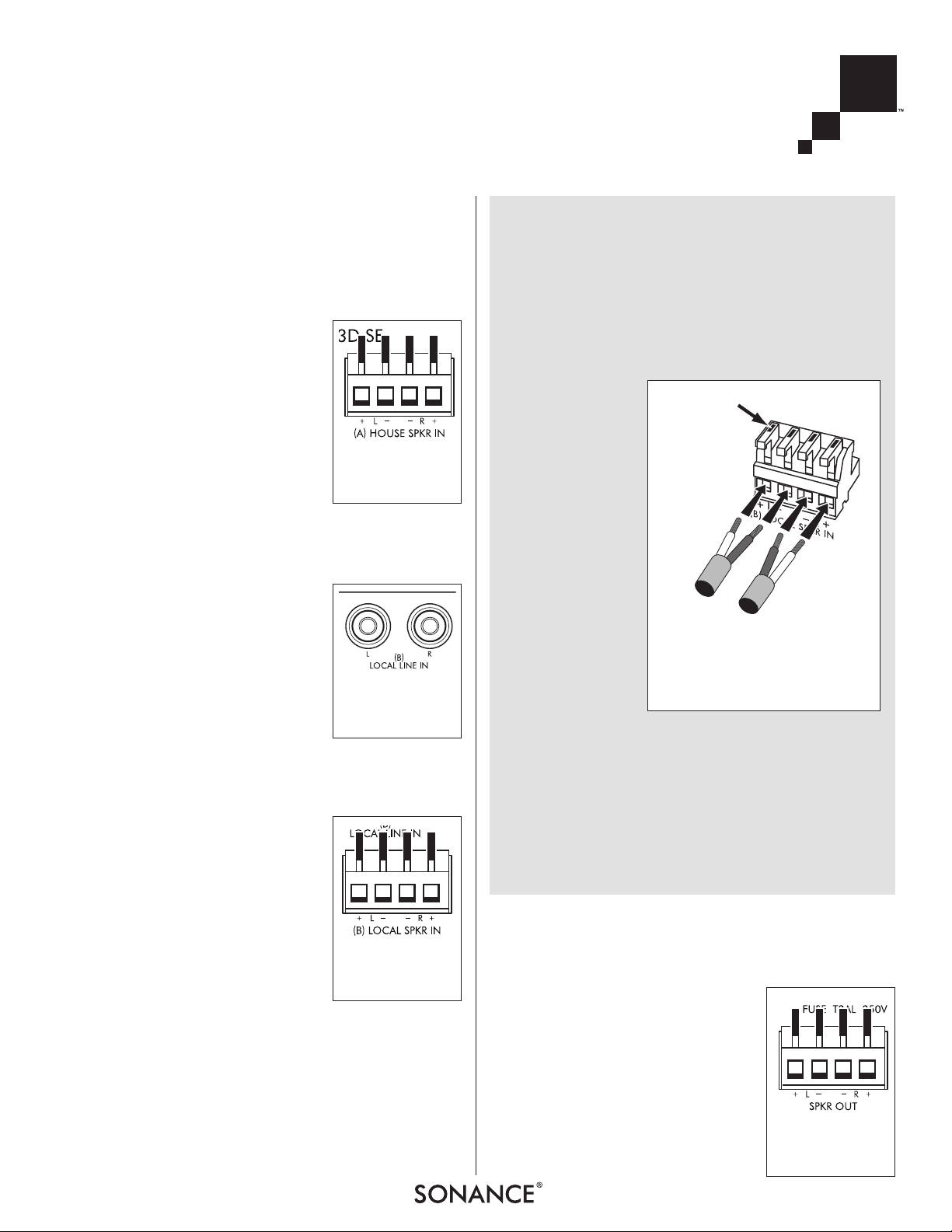
HOUSE SPEAKER IN Connector
The component connected to the HOUSE
SPEAKER IN connector (see
Figure 5
) is
the amplifier’s default input signal that
is passed (unamplified) to the speakers
when no control trigger stimulus is
applied. Typically, this is the room’s
speaker output from a whole-house
audio system.
The H
OUSE SPEAKER IN connector uses a
removable 4-wire quick connector that
accepts bare wire up to 14AWG. To
wire the connector see the sidebar in the next column.
LOCAL LINE IN Jacks
If the local source component has a set
of Line Output jacks, use a stereo RCA
cable to connect them to the ASAP3D
SE’s L
OCAL LINE IN jacks (see
Figure 6
).
The signal at the Local Line In jacks will
be amplified and sent to the ASAP3D
SE’s S
PEAKER OUTPUT connector whenev-
er the amplifier’s automatic switching
is triggered (see
Control Inputs/
Outputs
, on page 7).
LOCAL SPEAKER IN Connector
If the local source component does not
have a set of Line Output jacks, use
speaker wire to connect its Speaker
Outputs to the ASAP3D SE’s L
OCAL
SPEAKER IN connector (see
Figure 7
).
The signal at the L
OCAL SPEAKER IN con-
nector will be amplified and sent to the
ASAP3D SE’s S
PEAKER OUTPUT connector
whenever the amplifier’s automatic
switching is triggered (see
Control
Inputs/Outputs
, on page 7).
The L
OCAL SPEAKER IN connector uses a removable 4-wire
quick connector that accepts bare wire up to 14AWG. To wire
the connector see the sidebar in the next column.
NOTE: THE
L
OCALSPEAKERIN
CIRCUIT IS COMPLETELY ISOLATED
FROM GROUND AND IS COMPATIBLE WITH FLOATING GROUND OR
BRIDGED AMPLIFIER OUTPUT SIGNALS
.
Audio Output Connections
I
MPORTANT: ALWAYS UNPLUG THE AMPLIFIER’ S POWER
CORD FROM THE WALL OUTLET BEFORE MAKING AUDIO,
CONTROL OR SPEAKER CONNEC
-
TIONS
.
SPEAKER OUTPUT Connector
Connect the speakers in the local area
to the ASAP3D SE’s Speaker Output
connector (see
Figure 9
). These speakers will play whichever input source
the ASAP3D SE has switched ON (see
Control Inputs/Outputs
, on page 7).
FIGURE 7:
L
OCAL SPEAKER IN
CONNECTOR
Wiring the Removable Quick Connectors
1. Mark each wire’s positive (“+”) and negative (“–”)
leads and its channel (left or right).
2. Strip no more than
1
/8” of insulation from each wire.
Twist the strands to ensure that there are no stray
strands. (Stray strands that touch other or touch the
amplifier chassis can cause a short-circuit that can
damage the amplifier.)
3. Insert a small
screwdriver into
the slot on each
lever to open
the connector
terminals (see
Figure 8
).
4. Insert the
exposed portions of the
wires into the
terminal openings. Make sure
to insert the ‘+’
and ’–’ leads
into the correct
openings as
indicated in the
chassis markings below the connector.
5. After making sure that there are no stray wire strands
touching each other, flip the levers down to lock the wires
in the terminals.
6. Press the removable connector into the rear-panel
connector until it locks into place.
• The removable connectors will only fit one way on
the amplifier.
+
+
–
–
L Speaker
R S
p
eaker
Insert Small
Screwdriver
into Slots to
Flip Levers
Open
F
IGURE 8:
M
AKING CONNECTIONS TO THE
REMOVABLE QUICK CONNECTORS
F
IGURE 5:
H
OUSE SPEAKER IN
CONNECTOR
F
IGURE 6:
L
OCAL LINE IN
JACKS
FIGURE 9:
S
PEAKER OUTPUT
CONNECTOR
Page 7
7
SONAMP®ASAP3D SE STEREO POWER AMPLIFIER
The SPEAKER OUTPUT connector uses a removable 4-wire quick
connector that accepts bare wire up to 14AWG. To wire the
quick connector see the sidebar on page 6.
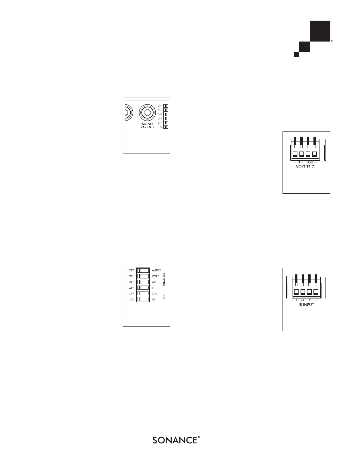
Mono Fixed/Variable Output
The MONO VAR OUTPUT jack (see
Figure
10
) supplies a sum of the left & right
channel signals from the L
OCAL LINE IN
or LOCAL SPEAKER IN connections.
The signal from the M
ONO VAR OUTPUT
jack is ideal for driving a powered
subwoofer, enabling the local system to
deliver improved bass performance that will greatly enhance
the listening experience when playing film soundtracks or
musical performance videos.
Volume changes made with the front-panel I
NPUT SENSITIVITY
adjustments or via IR commands will also effect the level of
the M
ONO V
AR OUTPUT, so the subwoofer will track volume
adjustments made to the local main speakers.
NOTE: YOU CAN CHANGE THE M ONO VAR OUT TO A FIXED-
LEVEL OUTPUT BY SWITCHING AN INTERNAL JUMPER. FOR DETAILS
SEE
A
PPENDIX
1
,
ON PAGE
13.
Control Inputs/Outputs
IMPORTANT: ALWAYS UNPLUG THE AMPLIFIER’S POWER
CORD FROM THE WALL OUTLET BEFORE MAKING CONTROL
CONNECTIONS.
The ASAP3D SE has a set of rear-panel
DIP switches (see
Figure 11
) that lets
you select the different methods for
triggering the switch from the House
source to the Local source.
A
UDIO: The presence of a 10mV or
higher audio signal at the L
OCAL LINE IN
or LOCAL SPEAKER IN inputs will switch
the ASAP3D SE to the Local source.
V
OLT: The presence of a 5 ~ 24V AC or DC external control
voltage at the V
OLTAGE TRIGGER input will switch the ASAP3D
SE to the Local source. See
Voltage Trigger Connections
, next
column.
AC: The ASAP3D SE will switch to the Local source when a TV
set that is connected to the ASAP3D SE’s AC Trigger Outlet is
turned ON. See
AC Trigger Outlet
, on page 8.
IMPORTANT: YOU CAN ONLY USE ONE OF THE ABOVE
TRIGGERING METHODS AT A TIME. IF MORE THAN ONE
METHOD IS SELECTED THE ASAP3D SE WILL ENTER A PRO-
TECT CONDITION AND WILL NOT SWITCH TO THE LOCAL
SOURCE (SEE
STATUS LEDS ,
ON PAGE 9). IF NO TRIGGER IS
SELECTED THE AMPLIFIER WILL PASS THE H OUSE SOURCE TO
THE SPEAKERS BUT WILL NOT SWITCH TO THE LOCAL SOURCE.
IR: The ASAP3D SE will switch to the Local source when it
receives an amplifier ON command from a connected IR control device.
NOTE: THE IR TRIGGER CAN BE SELECTED ALONG WITH THE
AUDIO, VOLTAGE OR
AC TRIGGER
, TO ALLOW IR CONTROL OF
VOLUME
, MUTE AND
BBE ON/OFF IN THESE CONTROL MODES
.
IR
Z
ONE
ON
AND
Z
ONE
OFF
COMMANDS ARE IGNORED.
Voltage Trigger Connections
When the ASAP3D SE’s VOLT
trigger
mode switch is set to the ON position,
the source can be switched from House
to Local by an external trigger voltage
appearing at the V
OLTAGE TRIGGER IN
connections (see
Figure 12)
. The trigger voltage must be between 5V and
24V, either AC or DC, usually supplied
by the
Status
output from an IR control
system.
The V
OLTAGE
TRIGGER OUT connection (see
Figure 12
) supplies
a 12V DC trigger signal whenever the Local source is ON.
This trigger can be used to control other devices, such as
Sonance AL2/AS2 automatic secondary switches, other
Sonamps or 12V DC relays.
The V
OLTAGE
TRIGGER connections feature a removable 4-wire
quick connector similar to the ones used for the speaker
connections. To wire the connector see the sidebar on page 6.
IR Input
The IR I
NPUT connection (see
Figure 13
)
allows the ASAP3D SE’s Local/House
source switching to be triggered by an
IR signal from a keypad controller or
other IR control device.
The IR I
NPUT connections feature a
removable 16AWG 4-wire quick
connector similar to the ones used for
the speaker connections. To wire the
connector see the sidebar on page 6.
The connections are as follows:
+ = +12V DC D = Data
GND = Ground S = Status
IR control codes for the ASAP3D SE can be downloaded from
the Sonance website: www.sonance.com.
FIGURE 10:
M
ONO VAR OUT
JACK
FIGURE 11:
T
RIGGER MODE
DIP SWITCHES
FIGURE 12:
V
OLTAGE TRIGGER
CONNECTIONS
FIGURE 13:
IR I
NPUT
CONNECTIONS
Page 8

SONAMP®ASAP3D SE STEREO POWER AMPLIFIER
8
IR Pass-Thru Outputs
The IR PASS-T
HRU OUTPUT connectors
(see
Figure 14
) pass IR signals
received at the IR I
NPUT connector (see
above) and IR Bus input. They are
designed for connection of IR emitters
like the Sonance E1, E2, VE1 and VE2.
The connectors accept 3.5mm mono
male plugs. A red LED located between
the connectors flashes to indicate IR activity.
IR Bus Connection
The IR Bus connection (see
Figure 15
)
links IR P
ASS THRU OUTPUT signals
between multiple ASAP3D SE
amplifiers, so that a single set of IR
emitters can respond to commands
from multiple IR controllers. This is
useful if a single set of source components is being shared by different
amplifiers for different zones.
AC Trigger Outlet
The ASAP3D SE will sense when a TV
connected to the AC T
RIGGER OUTLET
(see
Figure 16
) is turned ON and will
switch to the Local source as long as
the AC T
RIGGER OUTLET is supplying
current to the TV. When the current
draw ceases the amplifier will switch
back to the House source.
The 120V version of the ASAP3D SE
includes an IEC power cable with one
end designed to connect to a TV’s power cable. The other
end has a male IEC power connector that is designed to connect to the amplifier’s AC T
RIGGER OUTLET.
To maximize the ASAP3D SE’s compatibility with a variety of
TVs, the trigger sensitivity of the AC T
RIGGER OUTLET is user-
adjustable. See
AC Trigger Button
, next column.
NOTE: THE AC TRIGGER O UTLET IS NOT FUSED. THE REAR- PANEL
AC FUSE PROTECTS THE ASAP3D SE CIRCUITRY ONLY.
Front Panel Indicators and Controls
Level Control Adjustment
IN ALL TRIGGER MODES EXCEPT FOR IR: The
front-panel Level Control [L, R] potentiometers (see
Figure 17
) control the
volume of the source connected to the
L
OCAL LINE IN or LOCAL SPEAKER IN jacks.
These can be used to balance the
volume of the Local source against the volume of the House
source (the volume of which is determined by the source component feeding the H
OUSE SPEAKER IN connections). Use a
small screwdriver or similar tool to adjust the potentiometers.
I
N THE IR TRIGGER MODE: The L [left] Level Control potentiometer
sets the maximum volume level that both amplifier channels
will achieve when responding to IR volume commands.
Volume commands above that level will be ignored.
N
OTE: AMPLIFIER VOLUME, MUTING AND BBE ON/OFF
CAN BE
CONTROLLED VIA
IR REGARDLESS OF WHICH TRIGGER MODE IS
SELECTED
.
SENSE [Audio Trigger Sensitivity] Adjustment
The amount of Local source audio input
voltage required to switch the ASAP3D
SE from the House source to the Local
source can be adjusted with the frontpanel S
ENSE potentiometer (see
Figure
18
). Turning the control clockwise
decreases the trigger sensitivity
(requires more signal to trigger the
input change).
• The minimum signal required for
triggering is 5mV; the maximum is 4.5V. The factory
setting is 5mV.
Audio Switching Delay Adjustment
When the AUDIO trigger mode is active,
the amount of time it takes for the
ASAP3D SE to revert back to the House
source after the L
OCAL input audio sig-
nal has ceased can be adjusted with
the front-panel D
ELAY potentiometer
(see
Figure 19
). Turning the control
clockwise increases the delay time.
• The minimum delay time is 3
seconds; the maximum is 2 minutes. The factory setting is
3 seconds.
NOTE: IN THE
V
OLTAGE
AND
AC
TRIGGER MODES, REVERSION
BACK TO THE
HOUSE SOURCE IS INSTANTANEOUS AFTER THE
TRIGGERING EVENT CEASES
.
STBY [Standby] Pinhole Switch
Pushing the STBY pinhole switch (see
Figure 20
) disables the automatic input
triggering and passes the House source
through to the speaker outputs. The
H
OUSE LED (see
Status LEDs
, on page 9)
will flash once every 5 seconds to indicate the standby condition.
Pushing the S
TBY button again will
restore normal operation.
FIGURE 16:
AC T
RIGGER
OUTLET
FIGURE 17:
L
EVEL CONTROL
ADJUSTMENTS
FIGURE 19:
S
WITCHING DELAY
ADJUSTMENT
FIGURE 20:
S
TBY [STANDBY]
B
UTTON
FIGURE 18:
A
UDIO TRIGGER
S
ENSITIVITY
ADJUSTMENT
FIGURE 15:
IR B
US
CONNECTIONS
FIGURE 14:
IR P
ASS-THRU
OUTPUT
CONNECTORS
Page 9

9
SONAMP®ASAP3D SE STEREO POWER AMPLIFIER
AC TRIG [AC Trigger] Pinhole Switch
The AC TRIG pinhole switch (see
Figure
21
) lets the ASAP3D SE determine the
precise voltage appearing at its AC
T
RIGGER OUTLET
that will trigger the
amplifier to switch from the House to
the Local source:
1. Place the TV that is connected to the
AC T
RIGGER OUTLET
in the
Standby
or
OFF
mode.
2. Push the AC T
RIG button.
• The H
OUSE AND BBE LEDs on the ASAP3D SE’s front panel
will flash and the amplifier’s microprocessor records the
(minimum) voltage level at the AC T
RIGGER OUTLET.
3. Turn the TV’s power ON.
4. Push the AC T
RIG button again.
• The ASAP3D SE’s microprocessor records the (maximum)
voltage level at the AC Trigger Outlet,
5. The ASAP3D SE calculates an AC trigger voltage that is
between the maximum and the minimum voltage levels that
will appear at the AC T
RIGGER OUTLET. (This allows the
amplifier to switch sources when the TV turns ON.)
• When this process is completed the H
OUSE AND BBE LEDs
will stop flashing.
NOTE: THE ASAP3D SE WILL STAY IN THE H OUSE SOURCE
MODE FOR APPROXIMATELY
2 SECONDS AFTER THE TV SWITCHES
ON. THIS PREVENTS ANY ANNOYING TV SWITCHING NOISES
FROM BEING AMPLIFIED THROUGH THE SYSTEM
’S SPEAKERS.
To reset the AC Trigger Voltage to its factory level, unplug the
amplifier’s AC cord and plug it back in while holding-in the
AC T
RIG pinhole switch.
Status LEDs
The ASAP3D SE front
panel has three LEDs (see
Figure 22
) that provide
the amplifier’s normal
operating status:
H
OUSE: Illuminates when
the House source is active.
L
OCAL: Illuminates when the Local source is active.
BBE: Illuminates when BBE Sound Enhancement is active.
The H
OUSE LED also flashes to indicate various protection and
operational error conditions (see table in
Appendix 3
, on
page 14).
BBE®Sound Enhancement
The Sonamp ASAP3D SE incorporates
BBE
®
Sound Enhancement. The BBE
process improves music’s presence and
detail, especially at lower listening volumes. This improves the sound of your
audio system, particularly distributed
audio systems playing background
music. BBE also restores clarity and
definition (or focus) to spoken voices,
which makes paging systems easier to
understand without having to run them
at high volumes.
The ASAP3D SE has 2 individual switches to set the BBE
enhancement (see
Figure 23
):
• If the BBE ON/OFF switch is set to OFF, BBE enhancement
is not applied.
• If the BBE ON/OFF switch is set to ON, BBE enhancement
is applied according to the setting of the
LO/HI switch: LO = +3dB of BBE enhancement; HI = +6dB
of BBE enhancement.
Specifications
Number of Channels: 2 (one stereo pair)
Output Power (Stereo): 25 watts RMS per channel, 0.25% THD,
20Hz – 20kHz, @ 8 ohms
50 watts per channel, 0.25% THD,
1kHz, @ 4 ohms
Frequency Response: 20Hz – 20kHz ±2dB
Total Harmonic Distortion: 0.10% (1kHz, 8 ohms);
0.25% (1kHz, 4 ohms)
Signal to Noise Ratio: -94dB (w/22kHz filter, A-WTD);
-88dB (with AC-sensing trigger)
Input Sensitivity: 0.9V for 25W RMS output
0.7V w/BBE ON (+3dB)
0.5V w/BBE ON (+6dB)
Input Impedance: 13k ohms
Maximum Source Input: 2.3VAC RMS
Voltage 1.3VAC RMS w/BBE ON
Power Consumption: 200 Watts
Heat Output: 187 BTU/hr
AC Fuse: 2A (T2AL ~ 250V)
Dimensions (W x H x D): 9½” x 1¾” x 12½”
(241mm x 45mm x 318mm)
Rack Space Requirements: 1U (½-rack width)
Weight: 7.0 lbs (3.2kg)
FIGURE 21:
AC T
RIGGER
[AC TRIG
] BUTTON
FIGURE 22:
F
RONT-PANEL STATUS LEDS
FIGURE 23:
BBE M
ODE DIP
S
WITCHES
Page 10

SONAMP®ASAP3D SE STEREO POWER AMPLIFIER
10
Installation Examples
The illustrations on these pages show the wide variety of audio and audio/video systems that can be assembled using one or
more Sonamp ASAP3D SE amplifiers. Your local Authorized Sonance Dealer is an expert in audio/video system planning and
installation. Sonance strongly recommends that you work with your dealer to ensure that your system is properly planned,
assembled and installed.
ASAP3D SE System with AC Triggering
Figure 24
shows the typical system connections when triggering the ASAP3D SE via AC. The L
OCAL LINE IN and LOCAL SPEAKER
IN
connections are both shown for illustrative purposes. Although they both can be used simultaneously, normally only one
would be used.
min
Level
max
Phase
0
180
on
off
Bypass
50 250
Xover
S
PEAKER OUTPUT
From
L
INE OUT
TV
Power
Cord
To L
INE IN
F
ROM
S
PEAKER
O
UT
F
ROM SPEAKER OUT
Whole-Home Audio System
Bedroom
Speaker
Bedroom
Subwoofer
Bedroom
Speaker
Bedroom TV
ASAP3D SE
IEC Adapter Cable
(Supplied w/120V
version)
OR
FIGURE 24: TYPICAL CONNECTIONS WHEN USING AC TRIGGERING
Page 11

11
SONAMP®ASAP3D SE STEREO POWER AMPLIFIER
ASAP3D SE System with IR Triggering
Figure 25
shows the typical system connections when triggering the ASAP3D SE via IR from a keypad controller or other IR
control device. If multiple ASAP3D SEs are being used their IR BUS connections can be linked, allowing each of their IR
control devices to send signals to a single set of IR emitters on a set of source components being shared by all the systems.
min
Level
max
Phase
0
180
on
off
Bypass
50 250
Xover
S
PEAKER OUTPUT
K
EYPAD CONTROLLER
O
UTPUT
From
L
INE OUT
VE1
IR Emitter
To IR I
NPUT
TV
Power
Cord
To L
INE IN
F
ROM
S
PEAKER
O
UT
F
ROM SPEAKER OUT
W
ALL
O
UTLET
Whole-Home Audio System
Bedroom
Speaker
Bedroom
Subwoofer
Bedroom
Speaker
IR Keypad
Controller
Bedroom TV
ASAP3D SE
OR
TO IR BUS
OF SECOND
ASAP3D SE
F
IGURE 25: TYPICAL CONNECTIONS WHEN USING IR TRIGGERING
Page 12

ASAP3D SE System with Individual Zone IR Controller
Figure 26
shows the typical system connections when using the ASAP3D SE as a sub-zone amplifier, being driven by the audio
signal from one zone of a multi-zone controller.
SONAMP®ASAP3D SE STEREO POWER AMPLIFIER
12
Master Bedroom
Speakers
Master Bedroom
Keypad Controller
Master Bathroom
Ke
yp
ad Controller
Master Bathroom
Speakers
ASAP3D SE
DAB1 Mu
l
ti-Zone Controller
Set
Zone Line Output
to F
IXED
2/1
Adapter
FIGURE 26: TYPICAL CONNECTIONS WHEN USING AN INDIVIDUAL Z ONE IR CONTROLLER
Page 13

13
SONAMP®ASAP3D SE STEREO POWER AMPLIFIER
Appendix 1: Changing the Mono Variable Output to a Fixed Output Level
The M
ONO VAR OUT is factory-set to
Variable
via a jumper on the amplifier PCB. To change the output to a fixed level (which
is not affected by the front-panel L and R Input Level Controls or by IR volume commands):
1. Unplug the amplifier’s power cord from the Power Cord Connection on the back of the amplifier.
2. Remove the 8 screws (4 on top and 2 on each side) that secure the amp’s chassis cover.
3. Locate the M
ONO OUT section on the circuit board (see
Figure 27
).
4. Remove the jumper from the center pin and the “V” (variable) pin and re-insert it between the center pin and the “F” (fixed)
pin (see
Figure 28
).
5. Replace the amplifier’s chassis cover and screws, and plug the power cord back into the Power Cord Connection.
Appendix 2: IR Command List
The following ASAP3D SE functions can be controlled via IR:
Variable
Jumper Jumper
Fixed
Front
Panel
M
ONO OUT
Jumper
FIGURE 27: MONO OUT JUMPER LOCATION
FIGURE 28: CHANGING THE JUMPER FROM
F
IXED
TO
V
ARIABLE
• Amplifier ON (Local source active)
• Amplifier OFF (House source active)
• Mute ON
• Mute OFF
• Mute Toggle ON/OFF
• Volume –1 (Down one step)
• Volume +1 (Up one step)
• Volume –3 (Down three steps)
• Volume +3 (Up three steps)
• Volume –5 (Down five steps)
• Volume +5 (Up five steps)
• Volume 0 (Jump to 0)
• Volume 20 (Jump to 20)
• Volume 40 (Jump to 40)
• Volume 60 (Jump to 60)
• Volume 80 (Jump to 80)
• Volume 100 (Jump to 100)
• BBE ON
• BBE OFF
• BBE Toggle ON/OFF
Page 14

SONAMP®ASAP3D SE STEREO POWER AMPLIFIER
14
Appendix 3: Front-Panel LED Fault Indications
Technical Assistance and Service
If you have any questions about the operation or installation of this product, please call our Technical Assistance Department
on any business day at (800) 582-0772 or (949) 492-7777; from 7 a.m. to 5 p.m., PST.
If your amplifier should need repair or service, contact your Sonance Authorized Dealer for help, or use the following procedure:
1. Prior to calling note the product’s model number, serial number, purchase date, and the name and address of the dealer
where you purchased the product.
2. Contact our Technical Assistance Department at the above number(s) and describe the problem the unit is experiencing. If
applicable, they will issue a Return Authorization Number.
IMPORTANT: You must have prior authorization to return your amplifier to Sonance!
3. If you’re directed to return the unit to Sonance for repair, pack the unit in its original shipping carton. If needed, you can
obtain replacement packaging from us for a small charge. It is best if you place the box into an additional outer “overcarton” before shipment to minimize a chance of theft in shipment. Please include a copy of the original bill of sale inside the
package.
4. Contact a package delivery service such as United Parcel Service or Federal Express to arrange prepaid (not collect) ship-
ping. Do not use the U.S. Postal Service.
IMPORTANT: Freight collect shipments will be refused.
5. Write the Return Authorization Number on the outside of the shipping carton.
6. Ship the packaged unit to:
Quality Assurance Department
Sonance
212 Avenida Fabricante
San Clemente, CA 92672-7531
1 Flash every 2 seconds
More than 1 Trigger Mode switch
(A
UDIO
, V
OLT
, AC) is set to ON
Amplifier output muted
Amplifier output muted
Amplifier output mutes for
5 seconds, then turns back ON
Set only 1 A
UDIO
, V
OLT
or AC Trigger Mode
switch to ON
1 Flash every 5 seconds
Amplifier is in S
TANDBY
mode
Amplifier will not switch to
L
OCAL
source
Press front-panel STBY button
2 Flashes every 2 seconds
3 Flashes every 2 seconds
Over-Temperature
Over-Current; Short-circuit in
speaker output
H
OUSE
LED Action Cause Condition Remedy
Unplug the AC cord, wait 30 seconds,
then plug the AC cord back in
No action necessary if the amplifier remains
ON*
*If the amplifier goes into Over-Current or Short-Circuit protection 5 times in 1 minute it will shut-down. After correcting the over-current
condition (speaker impedance too low, volume too high, short-circuit, etc), unplug the AC co
rd, wait 10 seconds, then plug the AC cord back in.
Page 15

15
SONAMP®ASAP3D SE STEREO POWER AMPLIFIER
Limited Warranty Coverage (U.S. Only)
Sonance warrants to the original retail purchaser only that this Sonance product will be free from defects in materials and
workmanship for a period of five (5) years, provided the product was purchased from a Sonance Authorized Dealer.
Defective products must be shipped, together with proof of purchase, prepaid insured to the Authorized Sonance Dealer from
whom they were purchased, or to the Sonance factory at the address listed on this instruction manual. Freight collect shipments
will be refused. It is preferable to ship this product in the original shipping container to lessen the chance of transit damage.
In any case, the risk or loss or damage in transit is to be borne by the purchaser. If upon examination at the factory or
Authorized Sonance Dealer it is determined that the unit was defective in materials or workmanship at any time during
this warranty period, Sonance or the Authorized Sonance Dealer will, at its option, repair or replace this product at no
additional charge, except as set forth below. If this model is no longer available and cannot be repaired effectively, Sonance,
at is sole option, may replace the unit with a current model of equal or greater value. In some cases where a new model is
substituted, a modification to the mounting surface may be required. If mounting surface modification is required, Sonance
assumes no responsibility or liability for such modification. All replaced parts and product become the property of Sonance.
Products replaced or repaired under this warranty will be returned to the original retail purchaser, within a reasonable time,
freight prepaid.
This Warranty does not include service or parts to repair damage caused by accident, disaster, misuse, abuse, negligence,
inadequate packing or shipping procedures, commercial use, voltage inputs in excess of the rated maximum of the unit, or
service, repair or modification of the product which has not been authorized or approved by Sonance. This Warranty also
excludes normal cosmetic deterioration caused by environmental conditions. This Warranty will be void if the Serial Number
on the product has been removed, tampered-with or defaced. This Warranty is in lieu of all other expressed warranties. If the
product is defective in materials or workmanship as warranted above, the purchaser’s sole remedy shall be repair or
replacement as provided above. In no event will Sonance be liable for any incidental or consequential damages arising out of
the use or inability to use the product, even if Sonance or an Authorized Sonance Dealer has been advised of the possibility
of such damages, or for any claim by any other party.
Some states do not allow the exclusion or limitation of consequential damages, so the above limitation and exclusion may not
apply. All implied warranties on the product are limited to the duration of this expressed Warranty. Some states do not allow
limitation on the length of an implied warranty. If the original retail purchaser resides in such a state, this limitation does not
apply.
Exclusions and Limitations
The warranty set forth above is in lieu of all other warranties, express or implied, of merchantability, fitness for a particular
purpose, or otherwise. The warranty is limited to Sonance products registered herein and specifically excludes any damage to
loudspeakers and other allied or associated equipment which may result for any reason from use with this product. Sonance
shall, in no event, be liable for incidental or consequential damages arising from any breach of this warranty or otherwise.
This warranty gives you specific legal rights, and you may have other rights which vary from state to state.
Page 16

33-4815 01/08
©2008 Sonance. All rights reserved. Sonance, Sonamp and OptiLinQ are registered trademarks of Dana Innovations.
“BBE” and its designs are the registered trademarks of BBE Sound, Inc. ICEpower is a registered trademark of Bang & Olufsen ICEpower.
Due to continuous product improvement, all features and specifications are subject to change without notice.
For the latest Sonance product specification information visit our website: www.sonance.com
SONANCE • 212 Avenida Fabricante • San Clemente, CA 92672-7531 USA • (800) 582-7777 or (949) 492-7777
FAX: (949) 361-5151 • Technical Support: (800) 582-0772
www.sonance.com
 Loading...