

SOMFY IXENGO S Installation Manual
EN
Installation manual
ES
Manual de instalación
PT
Manual de instalação
EL
Εγχειρίδιο εγκατάστασης
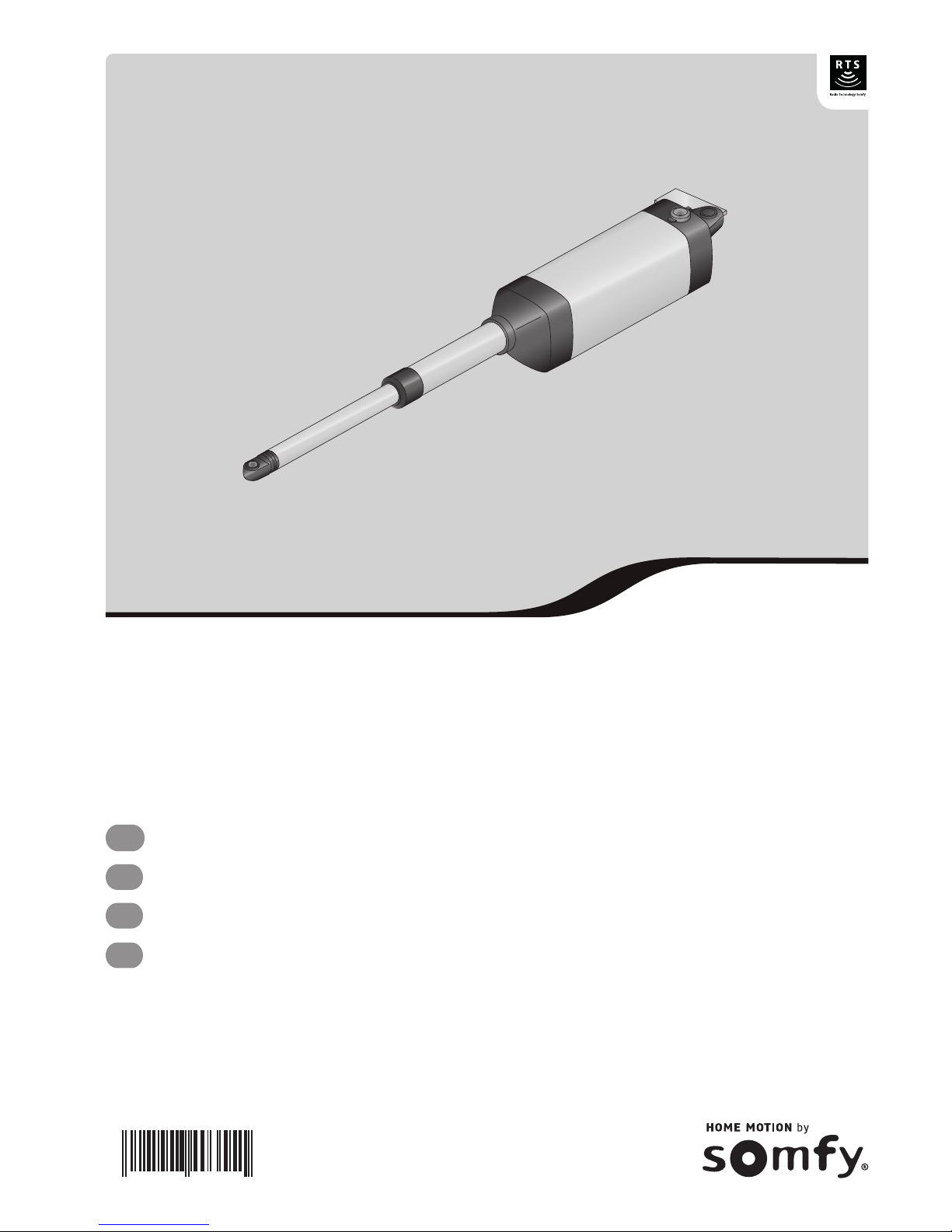
IXENGO S
D811858
8
027908 403551


1
Copyright © 2008 Somfy SAS. All rights reserved.
EN
cONtENtS
GENERAL __________________________________________________________________________________________________________2
SAFEtY INStRUctIONS
_____________________________________________________________________________________2
Warning 2
Safety instructions 2
PRODUct DEScRIPtION ____________________________________________________________________________________3
Components 3
Dimensions 3
Application 4
POINtS tO cHEcK PRIOR tO INStALLAtION ______________________________________________________4
Preliminary checks 4
Safety instructions 4
INStALLAtION ___________________________________________________________________________________________________5
Fitting the post mounting bracket 5
Fitting the gate section mounting bracket 6
Specic installations 7
Gate section limit stops on the ground 7
Electrical connections 7
ADJUStING tHE LIMIt StOPS - IXENGO S 24 v ____________________________________________________8
Adjusting the FC1 closing limit stop 8
Adjusting the FC2 closing limit stop 8
OPERAtING tESt _______________________________________________________________________________________________9
Opening the gate by hand 9
Checking operation 9
What do I do if the motor drive unit fails? 9
SPEcIFIcAtIONS ________________________________________________________________________________________________9
NOtES
_____________________________________________________________________________________________________________ 10

2
Copyright © 2008 Somfy SAS. All rights reserved.
EN
GENERAL
SAFEtY INStRUctIONS
This product, installed in accordance with this guide, complies with EN 12453 and EN 13241-1 standards.
The instructions referred to in the product Installation and Operating manuals are intended to meet the requirements of
property safety, personal safety and the above-mentioned standards.
Failure to comply with these instructions releases Somfy from any liability for damage that may be entailed.
We, Somfy, declare that this product is compliant with the essential requirements and other relevant stipulations of
directive 1999/5/EC. A compliance declaration is available from the following address www.somfy.com/ce. (Ixengo_S)
This product can be used in the European Union and in Switzerland.
Warning
Important: Please comply with all instructions, for incorrect installation may cause serious injury.
Safety instructions
Before installing the motor drive system, make sure that the driven part is in good working order, that it is correctly
balanced and that it opens and closes correctly.
Ensure that danger areas (where pinching, cutting, trapping may occur) between the driven parts and xed surrounding
parts due to the opening motion of the driven part are avoided.
Retain a clear 500 mm space behind each gate section when the gate is fully opened.
Any switch that does not lock into position (interphone, key switch, etc.) must be located in plain view of the driven part
but away from the moving parts.
Any switch installed must be at a minimum height of 1.5 meters and not be accessible to the public, except if it works
with a key.
Ensure that the motor drive system cannot be used with gate section including a wicket gate inhibiting motion
(unless the motor drive cannot operate with the wicket gate open).
After installation, make sure that the mechanism is correctly adjusted and that the protection system and any manual
release mechanism operate correctly.
Permanently afx the label describing the manual release mechanism close to its operating mechanism.
Wear protective glasses while performing drilling work.
To operate, the Ixengo S system requires a 230 V - 50 Hz mains supply. The electric power line:
• must be solely reserved for use by the Ixengo S,
• must have a minimum wire cross section of 1.5 mm
2
,
• must be provided with protection (a 10 A fuse or circuit breaker) and a residual current device (30 mA),
• must be tted with an omnipolar disconnection mechanism,
• must be installed in line with applicable electrical safety standards.
We recommend providing the installation with a surge arrester (in compliance with standard NF C 61740, with a
maximum residual voltage of 2 kV).
3
Copyright © 2008 Somfy SAS. All rights reserved.
EN
PRODUct DEScRIPtION
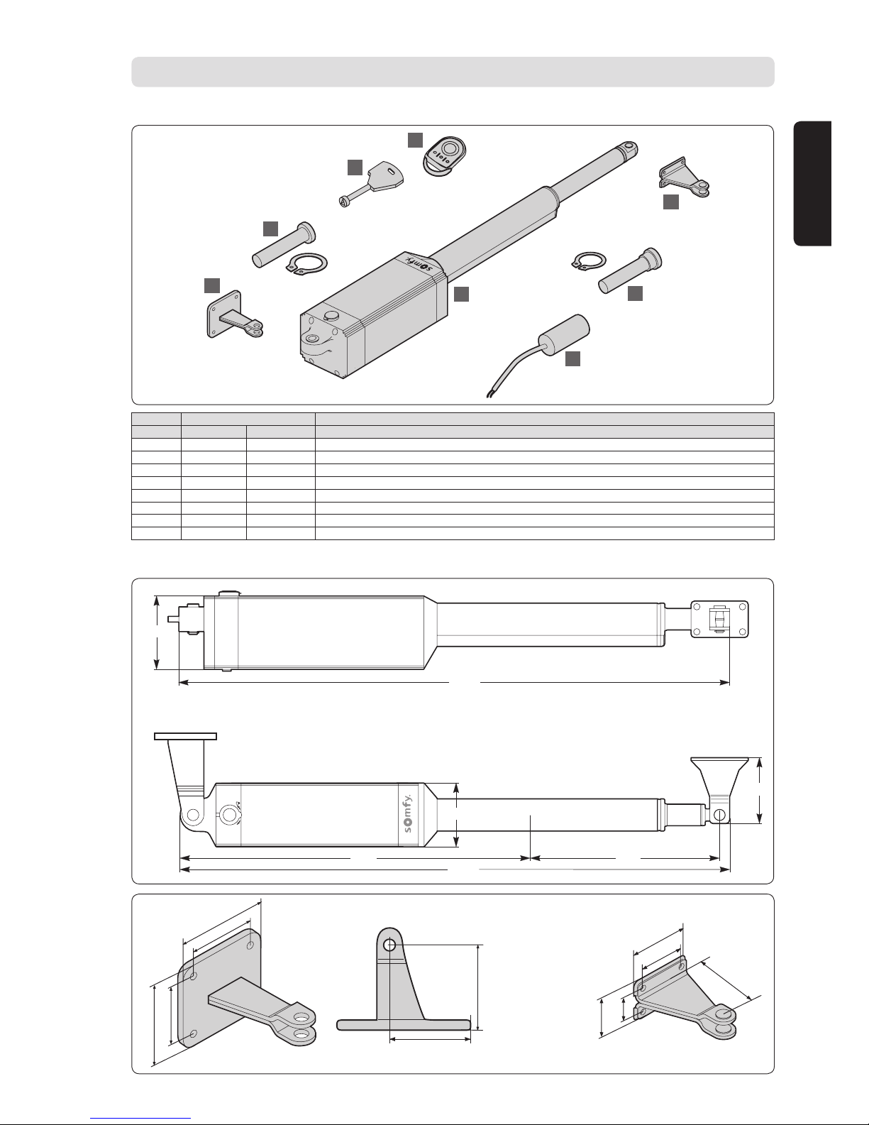
components
8
7
6
5
1
3
4
2
Dimensions
102
1027
1027
80
80
713
280
Key Number Description
Kit Motor only
1 2 1 Ixengo_S motor unit
2 2 1 Gate mounting bracket
3 2 1 Motor/gate mounting bracket hinge pin + circlips
4 2 1 Capacitor (Ixengo S 230 V only)
5 2 1 Gate post mounting bracket
6 2 1 Motor/gate post mounting bracket hinge pin
7 1 1 Unlocking key
8 2 0 Keygo RTS remote control
80
77
65
50
35
120
90
79
110
50
72,5
4
Copyright © 2008 Somfy SAS. All rights reserved.
EN
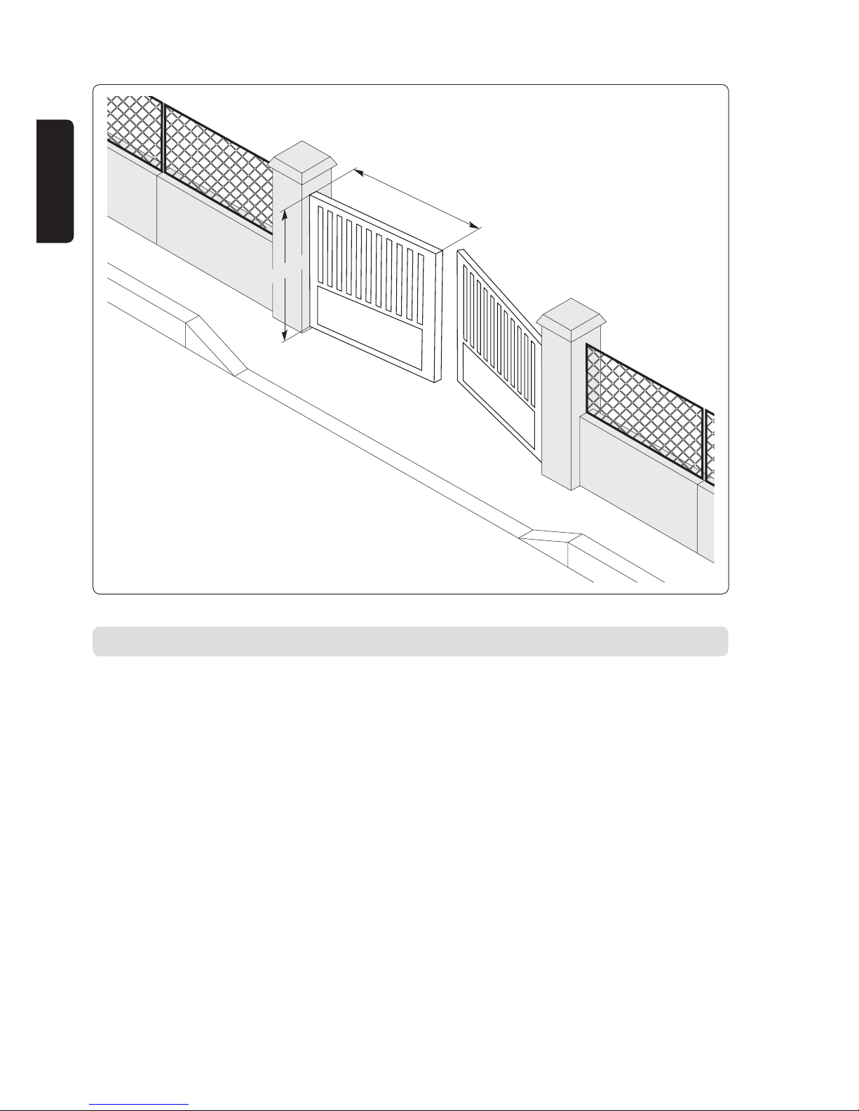
Application
1 m y L y 1,8 m
P y 250 kg
H y 2 m
POINtS tO cHEcK PRIOR tO INStALLAtION
Preliminary checks
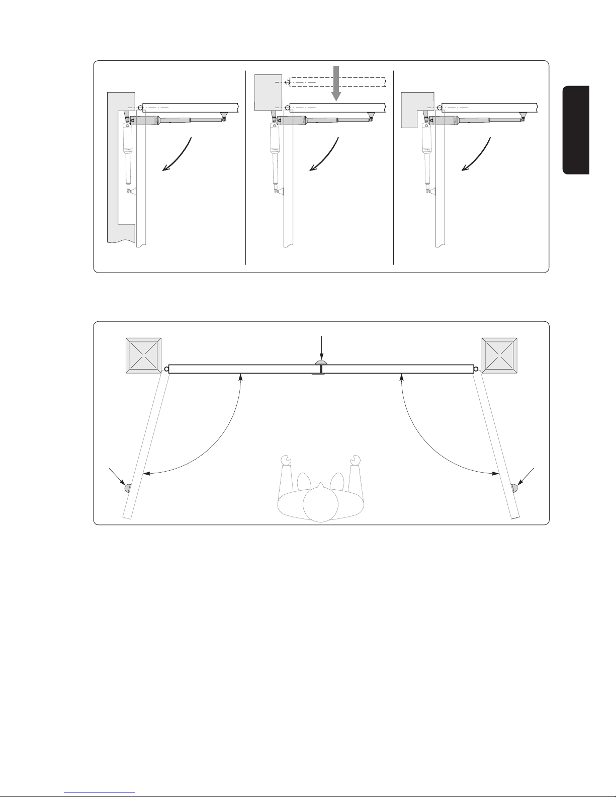
Ensure that the gate structure is strong enough. In all cases, the drive rod must push the gate section towards a
reinforced point.
It must be possible to move the gate by hand without encountering any hard point. Check that the gate is in good
condition and is perfectly balanced.
The gate section limit stops mounted on the ground must be provided for both the opening and closing directions. Somfy
recommends installing gate open limit stops to improve the way the gate is held open.
For an existing gate, check component wear. If necessary, repair or replace faulty or worn parts.
If the gate does not include any reinforcing, use metal reinforcing plates when attaching brackets.
Safety instructions
Be sure to follow these safety instructions throughout installation:
• Take off any jewellery worn (bracelet, neck chain or other) during installation
• During drilling and welding operations, always wear special goggles and suitable protective clothing
• Always use proper tools
• Never connect to the mains power or the battery backup before nishing the assembly process.
5
Copyright © 2008 Somfy SAS. All rights reserved.
EN
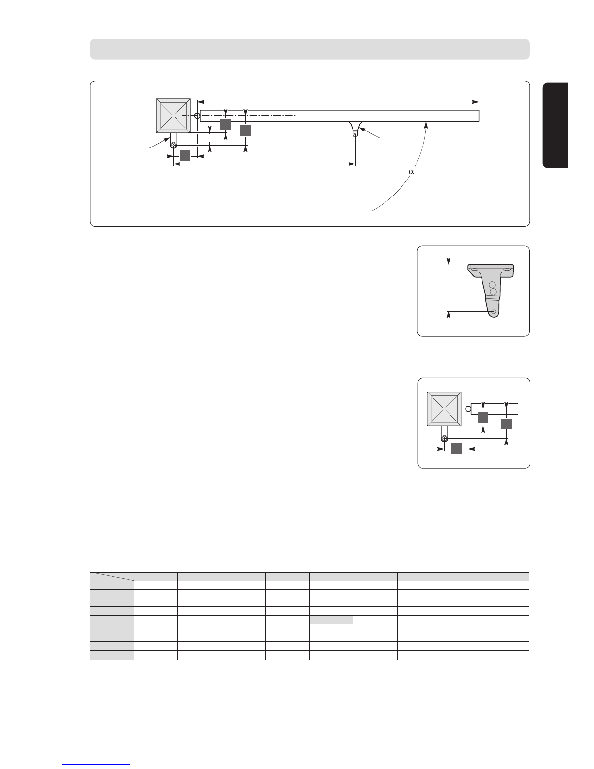
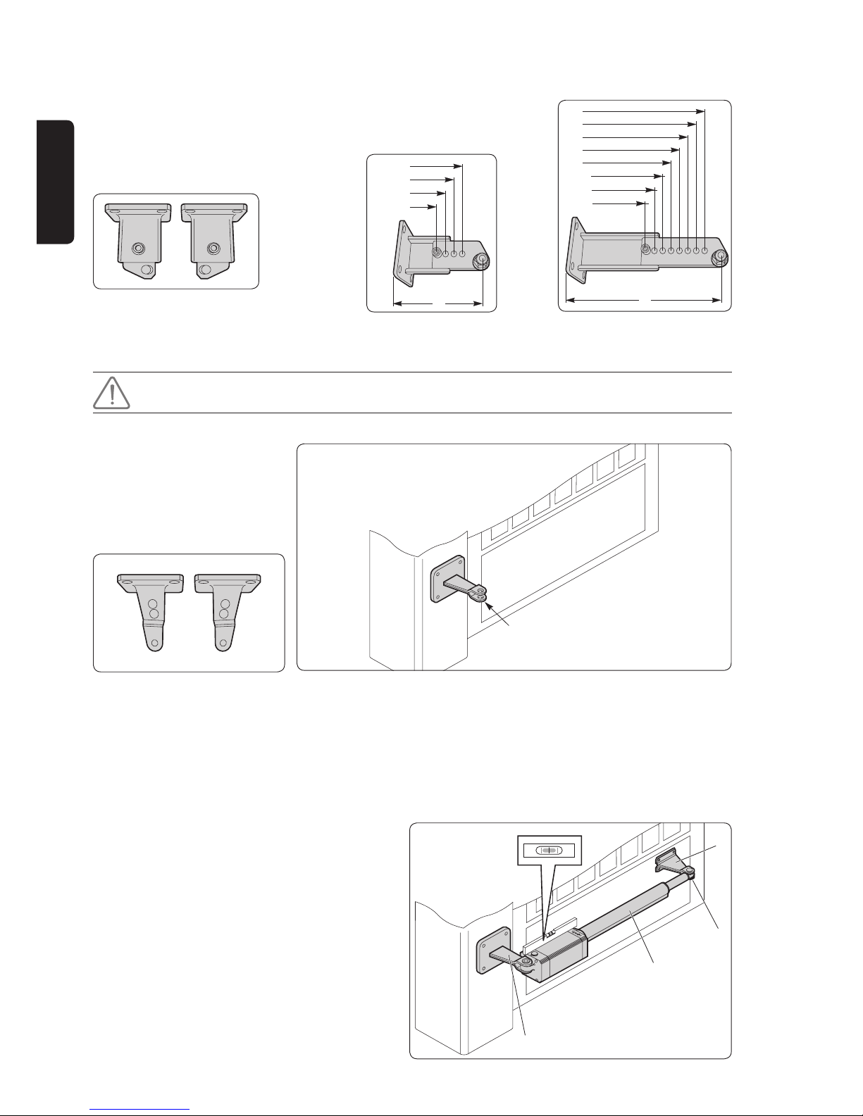
The gure below illustrates the dimensions to be dened for installation.
Z
P
C
D
°
F
X
A
B
Key:
A-B: dimensions used to determine where to t the post mounting bracket P
c: distance between mounts (recommended value: 993 mm)
X: distance from the gate centreline to the post edge
Z: distance between the post edge and the motor rotation centreline
α°: gate opening angle
P: post mounting bracket
D: gate section length
F: gate section mounting bracket
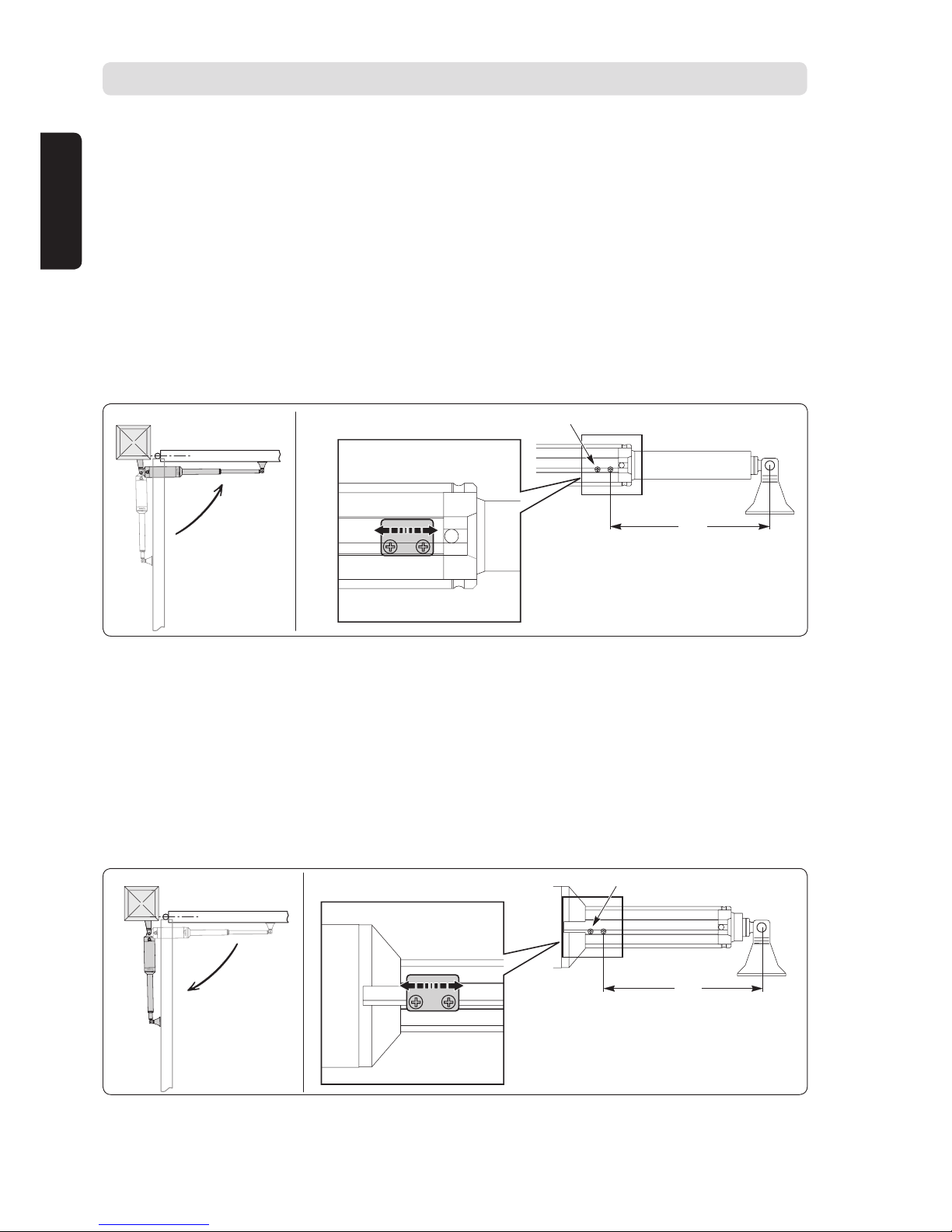
Fitting the post mounting bracket
• Dene the desired opening angle "α°".
• Measure the X dimension on the gate.
• Calculate B = Z + X given that Z = 110 mm
B
X
A
• From the table, choose A and B dimensions that are close to identical so as to match
the opening speed and ensure proper motor drive operation. If the chosen dimensions
are too far apart, gate section motion will not be constant and the push or pull torque
applied will vary during motion.
INStALLAtION
The table shows the optimum A and B values for an opening of α° = 90° at constant speed.
B
A
100 110 120 130 140 150 160 170 180
100 119 109 103 98 94 91
110 112 105 98 94 91
120 117 105 99 94 91
130 107 99 94 90
140 112 100 94 90
150 102 94 90
160 104 94 89
170 95 89
180 88
α°
Values of "A" and "B" can be chosen from the table based on the desired degree of opening "α°".
Z = 110
6
Copyright © 2008 Somfy SAS. All rights reserved.
EN
If dimension B is excessive:
• Use adjustable mounts (9014609 or 9014610) that allow setting the following four or eight values of Z (in cases where
you need to reduce or increase the value of Z):
P1: Z = 78 mm P5: Z = 155 mm P9: Z = 203 mm P11: Z = 227 mm
P2: Z = 90 mm P6: Z = 167 mm P10: Z = 215 mm P12: Z = 239 mm
P3: Z = 102 mm P7: Z = 179 mm
P4: Z = 114 mm P8: Z = 191 mm
Adjustable mount installation position
Left Right
• Or move the gate hinges so as to reduce distance B (refer to "Specic Installations").
• Attach the mounting bracket P.
Drill and bolt the mounting bracket to the post.
Use a type of mounting that suits the post.
Mount direction
P
Left Right
Note: Use the large circlips to attach the mounting bracket P.
Example
When the desired opening angle is 90°:
• Measure dimension X = 30 mm.
• Calculate dimension B = X + Z = 30 + 110 = 140 mm.
• Apply dimension B = 140 to the table and use a dimension A = 140 for a 90° opening.
Fitting the gate section
mounting bracket
Important: On the gate section, measure dimension c
(993 mm), the length between the two mounting bracket
centres. Mark the mounting axis for the gate section
mounting bracket.
[1] Release the motor drive unit E. Extend the drive rod till
the end of its travel.
[2] Temporarily t the motor drive unit on its mount P.
[3] Fit the gate section mounting bracket F onto the drive
rod E with its pivot pin G.
[4] Check that the motor drive unit E is horizontally aligned
using a spirit level.
[5] Attach the gate section mounting bracket F.
P1
P2
P3
P4
Z
P5
P6
P7
P8
P9
P10
P11
P12
Z
P
E
G
F
7
Copyright © 2008 Somfy SAS. All rights reserved.
EN
Specic installations
Installation with a niche
in a fence
Moving the gate
hinge
Installation with a niche
in a gate post
Gate section limit stops on the ground
H
H
H
Check for the presence of the gate section limit stops H on the ground.
For the motor drive unit to operate correctly, using limit stops on the ground is required for both the opening and closing
directions.
The ends stops in the ground apply physical pressure to the gate leaves, thus limiting the mechanical stress on the
cylinders (particularly in windy conditions).
Electrical connections
Make the connections between the motor drive unit and the Control Box 3S Ixengo electronic controller for Ixengo S 24 V
and FX 230 electronic controller for Ixengo S 230 V .
8
Copyright © 2008 Somfy SAS. All rights reserved.
EN
ADJUStING tHE LIMIt StOPS - IXENGO S 24 v
Adjust the limit stops by correctly positioning the end of travel magnets on the 24 V motor drive unit.
Important: For the 230 v motor drive unit, refer to the instructions on the FX 230 electronic controller and adjust
the time that the motor operates.
Adjusting the Fc1 closing limit stop
[1] Close the gate section.
[2] Slacken screws I and J on the closing limit stop.
[3] Move the limit stop so that the distance between screw J and the gate section mounting bracket axis is some 376 mm.
[4] Close the gate.
[5] If the gate section stops too soon in relation to the desired position, slightly move the limit stop towards the end of the
drive rod.
[6] If the gate section hits the limit stop on the ground when closing, and the motor drive unit reverses direction, then
move the limit stop slightly towards the motor drive unit's body.
[7] After correctly dening the limit stop's position, tighten down screws I and J.
I
J
376
FC1
Adjusting the Fc2 opening limit stop
[1] Open the gate section.
[2] Slacken screws K and L on the opening limit stop.
[3] Move the limit stop so that the distance between screw L and the gate section mounting bracket axis is some 376 mm.
[4] Open the gate.
[5] If the gate section stops too soon in relation to the desired position, slightly move the limit stop towards the motor
drive unit’s body.
[6] If the gate section hits the limit stop on the ground when opening, and the motor drive unit reverses direction, then
move the limit stop slightly towards the end of the drive rod.
[7] After correctly dening the limit stop’s position, tighten down screws K and L.
376
K
L
FC2
Note: When programming the electronic controller, always anticipate when the limit stops will take action. To properly
press against the limit stops on the ground, the motor drive unit continues its movement for 1 or 2 cm (some 100 ms).
9
Copyright © 2008 Somfy SAS. All rights reserved.
EN
OPERAtING tESt
Opening the gate by hand
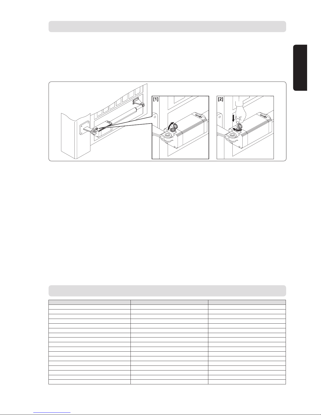
If necessary, the motor drive unit is provided with a release key so that the gate section can be moved by hand.
[1] After lifting the lock cover, insert the release key and turn it clockwise by 90°.
[2] Push the gate section by hand to open the gate.
[3] Turn the release key in the opposite direction to return to motor driven operation.
[4] Ret the lock cover.
checking operation
Before starting up the motor drive unit:
• Check that all components are solidly mounted
• Check all safety mechanisms for correct operation
• Check the emergency operation control
• Check that the electronic controller is operating correctly.
What do I do if the motor drive unit fails?
• Use a suitable instrument to check for the presence of voltage on the ends of the motor reduction gear unit after an
opening or closing operation.
• If the drive rod does not turn in the right direction, reverse the electrical operating connections on the motor reduction
gear unit.
• If the gate reverses direction after opening or closing, this means that the limit stops have not been correctly set. Refer
to the section called "Adjusting the limit stops" to rene the position of the limit stops.
SPEcIFIcAtIONS
24 v version 230 v version
Power supply 24 V DC 230 V AC
Rotation speed 3800 rpm 2800 rpm
Power consumption 40 W 210 W
Current consumption 1.5 A 0.8 A
Push and pull torque 2000 N 2000 N
Useful travel 280 mm 280 mm
Drive rod speed 14 mm/s 12 mm/s
Obstacle detection (impact reaction) Built-in torque limiter Electronic clutch on the control panel
Limit stops Built-in, magnetic and adjustable Manual operation By unlocking key By unlocking key
Nbr. of operations per 24 hours 60 operations 60 operations
Maximum gate section length 1800 mm 1800 mm
Maximum gate section weight 250 kg 250 kg
Ambient conditions -10°C to +60°C -10°C to +60°C
Protection level IP44 IP44
Lubrication Greased for life Greased for life
Capacitor - 6.3 µF

10
Copyright © 2008 Somfy SAS. All rights reserved.
EN
NOtES
____________________________________________________________________________________________________________
____________________________________________________________________________________________________________
____________________________________________________________________________________________________________
____________________________________________________________________________________________________________
____________________________________________________________________________________________________________
____________________________________________________________________________________________________________
____________________________________________________________________________________________________________
____________________________________________________________________________________________________________
____________________________________________________________________________________________________________
____________________________________________________________________________________________________________
____________________________________________________________________________________________________________
____________________________________________________________________________________________________________
____________________________________________________________________________________________________________
____________________________________________________________________________________________________________
____________________________________________________________________________________________________________
____________________________________________________________________________________________________________
____________________________________________________________________________________________________________
____________________________________________________________________________________________________________
____________________________________________________________________________________________________________
____________________________________________________________________________________________________________
____________________________________________________________________________________________________________
____________________________________________________________________________________________________________
____________________________________________________________________________________________________________
____________________________________________________________________________________________________________
____________________________________________________________________________________________________________
____________________________________________________________________________________________________________
____________________________________________________________________________________________________________
____________________________________________________________________________________________________________
____________________________________________________________________________________________________________
____________________________________________________________________________________________________________
____________________________________________________________________________________________________________
____________________________________________________________________________________________________________
____________________________________________________________________________________________________________
____________________________________________________________________________________________________________
____________________________________________________________________________________________________________
____________________________________________________________________________________________________________
____________________________________________________________________________________________________________
____________________________________________________________________________________________________________
____________________________________________________________________________________________________________
____________________________________________________________________________________________________________
____________________________________________________________________________________________________________
____________________________________________________________________________________________________________
____________________________________________________________________________________________________________
____________________________________________________________________________________________________________
____________________________________________________________________________________________________________
____________________________________________________________________________________________________________

1
Copyright © 2008 Somfy SAS. All rights reserved.
ES
ÍNDIcE
INtRODUccIÓN _________________________________________________________________________________________________2
INStRUccIONES DE SEGURIDAD
________________________________________________________________________2
Advertencia 2
Instrucciones de seguridad 2
DEScRIPcIÓN DEL PRODUctO ___________________________________________________________________________3
Componentes 3
Dimensiones 3
Aplicación 4
vERIFIcAcIONES ANtES DE LA INStALAcIÓN ____________________________________________________4
Comprobaciones preliminares 4
Instrucciones de seguridad 4
INStALAcIÓN _____________________________________________________________________________________________________5
Montaje de la brida de sujeción al pilar 5
Montaje de la brida de sujeción a la hoja 6
Casos particulares de instalación 7
Topes de suelo para detener las hojas 7
Conexiones eléctricas 7
AJUStE DE LOS tOPES DE FIN DE cARRERA - IXENGO S 24 v _____________________________8
Ajuste del n de carrera de cierre FC1 8
Ajuste del n de carrera de cierre FC2 8
PRUEBA DE FUNcIONAMIENtO __________________________________________________________________________9
Apertura manual 9
Comprobación de funcionamiento 9
Qué hacer en caso de funcionamiento defectuoso del cilindro 9
cARActERÍStIcAS tÉcNIcAS ___________________________________________________________________________9
NOtAS
_____________________________________________________________________________________________________________ 10

2
Copyright © 2008 Somfy SAS. All rights reserved.
ES
INtRODUccIÓN
INStRUccIONES DE SEGURIDAD
Este producto, instalado conforme a las presentes instrucciones, permite una puesta en servicio conforme a las normas
EN 12453 y EN 13241-1.
Las instrucciones citadas en los manuales de instalación y utilización del producto están destinadas a cumplir los
requisitos de seguridad de bienes y de personas, así como los de las mencionadas normas.
En caso de incumplimiento de estas instrucciones, Somfy declina toda responsabilidad por cualquier daño que pudiera
originarse.
Somfy declara que este producto se ajusta a los requisitos básicos y a otras disposiciones pertinentes de la directiva
1999/5/CE. Existe una declaración de conformidad para su consulta en www.somfy.com/ce. (Ixengo_S). Producto
utilizable en la Unión Europea y en Suiza.
Advertencia
Importante: observe todas las instrucciones, ya que una instalación incorrecta puede dar lugar a lesiones graves.
Instrucciones de seguridad
Antes de instalar la motorización, compruebe que el batiente esté en buen estado mecánico, correctamente equilibrado
y que se abra y cierre sin problemas.
Asegúrese de que no haya zonas peligrosas (aplastamiento, cizallamiento, atoramiento) entre el batiente y las partes
jas circundantes, a causa del movimiento de apertura.
Deje despejada una zona de 500 mm por detrás de cada hoja en posición de apertura total.
Cualquier interruptor sin bloqueo (interfono, contacto con llave, etc.) debe estar situado a vista directa del batiente,
aunque alejado de las partes móviles.
Debe estar instalado a una altura mínima de 1,5 m y no ser accesible al público, excepto si funciona con llave.
Compruebe que la motorización no se active si un batiente con portilla está obstaculizado (excepto si la motorización no
puede funcionar con la portilla abierta).
Tras la instalación, compruebe que el mecanismo esté ajustado correctamente y que el sistema de protección y todo
dispositivo de desembragado manual funcionen correctamente.
Fije de manera permanente la etiqueta relativa al dispositivo de desembragado manual junto a su mando de maniobra.
Utilice gafas durante el taladrado.
Ixengo S necesita una alimentación de 230 V – 50 Hz. La línea eléctrica debe:
• ser exclusiva para Ixengo S
• tener una sección mínima de 1,5 mm
2
• estar dotada de una protección (fusible o interruptor automático de 10 A) y de un dispositivo diferencial (30 mA)
• estar equipada con un dispositivo de desconexión omnipolar
• estar instalada según las normas vigentes de seguridad eléctrica.
Se recomienda incorporar un pararrayos a la instalación (según la norma NF C 61740, tensión residual máxima de 2 kV).
 Loading...