

SOMFY DECOFLEX DIGITAL WALL SWITCH SDN GROUP CONTROL, DECOFLEX DIGITAL WALL SWITCH ANIMEO IP, DECOFLEX DIGITAL WALL SWITCH SDN, DECOFLEX WIREFREE RTS, DECOFLEX DRY CONTACT KEYPAD Assembly/installation/operating Instructions
Page 1
DecoFlex Keypad
Instructions
ASSEMBLY
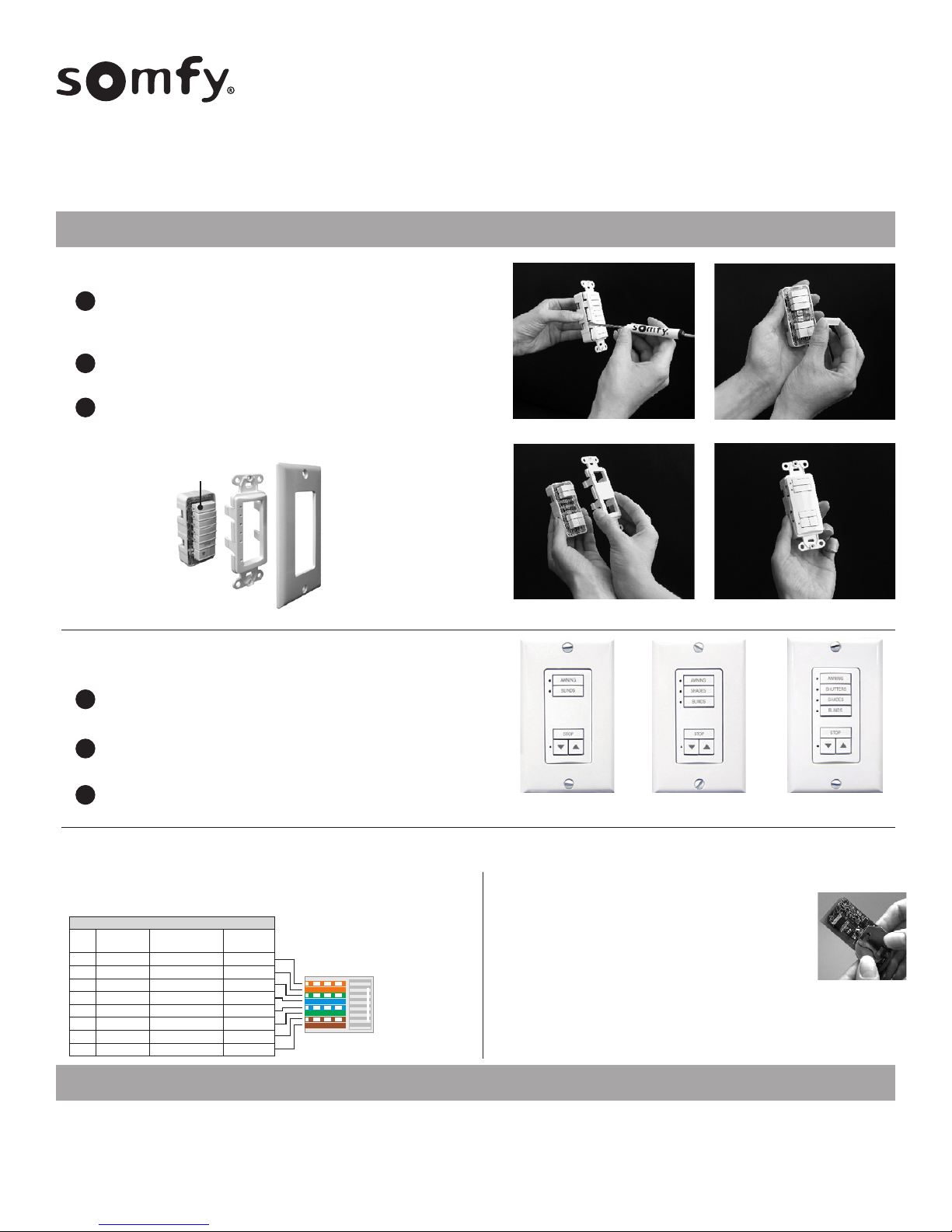
ASSEMBLE MULTIPLE BUTTON SWITCHES
Begin with a standard (assembled) 1 or 5 control button DecoFlex switch. Using
1
a small flat blade screw driver, carefully separate the SWITCH BASE ASSEMBLY
from the FACEPLATE (as shown in figure 1).
Add or remove CONTROL BUTTONS (as required) from the SWITCH BASE ASSEMBLY
2
(as shown in figure 2). Be certain the SWITCH BASE ASSEMBLY remains intact.
Attach new multiple button face plate (as shown in figure 3 & 4).
3
5 Channel DecoFlex Wall Switch (Exploded view)
Removable Channel
Buttons
Assembly/Installation/Operating Instructions
Applies to the following keypads:
DECOFLEX WIREFREE™ RTS (Ref: 1810813 +others)
DECOFLEX™ DIGITAL WALL SWITCHES SDN (Ref: 1811253 +others)
DECOFLEX™ DIGITAL WALL SWITCHES SDN GROUP CONTROL (Ref: 1811749, 1811750)
DECOFLEX™ DIGITAL WALL SWITCHES ANIMEO® IP (Ref: 1811289 +others)
DECOFLEX DRY CONTACT KEYPAD for IGC 4n1 Motor Controller (Ref: 1811402)
Figure 1.
Figure 2.
Switch Base
Assembly
8 Button
Faceplate
Wall Plate
REPLACE STANDARD CONTROL BUTTONS
Using a small flat blade screw driver, carefully separate the SWITCH BASE
1
ASSEMBLY from the FACEPLATE (as shown in figure 1).
Replace standard (blank) or temporary labeled CONTROL BUTTON(s) with
2
new printed CONTROL BUTTON(s).
3
Attach new CONTROL BUTTON FACE PLATE (as shown in figure 3 & 4).
POWERING DECOFLEX KEYPADS
SDN, animeo IP and Dry Contact
Keypad RJ45 Pinout:
CAT-5e or higher TIA-568B standard with RJ-45
Pin # Color
1 Orange White SDN RS485 ( + ) IP1
2 Orange SDN RS485 ( - ) IP2
3 Green White Reserved IP3
4 Blue Power 24v DC ( + ) 12V+
5 Blue White Power 24v DC ( - ) N/A
6 Green Reserved Down
7 Brown White SDN RS485 Ground Up
8 Brown SDN RS485 Ground Ground
SDN & animeo IP
Function
Dry Contact
Function
SDN Cable Pinout: (RJ45 connector)
ANSI/TIA/EIA 568-B Standard
6 Button
Figure 4.
7 Button
Switch Assembly
Figure 3.
5 Button
Switch Assembly
Switch Assembly
RTS
Battery Replacement: (RTS only)
The DecoFlex WireFree™ RTS switch is designed to provide years of maintenance
free performance. Should the battery become discharged, the LED indicator lights
will no longer function when the channel button is selected or an Up/Stop/Down
command is activated. As a result, the radio signal will be reduced or not
communicated to the RTS receiver or motor.
The battery can be easily replaced by exposing the SWITCH BASE ASSEMBLY board of the
DecoFlex WireFree™ switch. Simply slide the battery out of its holder and replace with a
new 3V Lithium battery (type 2450) maintaining the correct polarity.
NOTE: Batteries should be disposed of properly according to local regulations.
KEYPAD PROGRAMMING
Download and install Programming Soware from this link.
https://www.somfysystems.com/support/tools/configuration-tools-soware
RTS: Follow our RTS Pocket Programming Guide to setup DecoFlex RTS keypads
Dry Contact: Arrange switch for control in IGC 4n1 Motor Controller
*Before installing keypads all motors must be wired to the controller, have limits set and be working properly.
SDN: The DecoFlex Digital Keypads for SDN has programmable buttons which can be
configured to control any motor or group using the SDN Keypad Programming Guide and
SDN Keypad Configuration Soware. Once a keypad is fully configured, all of the settings
can be exported to a file for backup.
animeo® IP: Keypads are configured within the animeo® IP commissioning soware aer
installation on the SDN bus. Use animeo® IP Visual Configuration soware.
Page 2
DecoFlex Keypad
INSTALLATION
Included is a special SOMFY low voltage device mounting bracket which attaches to drywall and eliminates the need for an electrical box.
The bracket can be used in two mounting type configurations, they are as follows:
The bracket is specifically designed for mounting the DecoFlex range wall switches to an adjacent (pre-existing) Decora style light switch (see below).This
1
unique mounting bracket allows the necessary spacing for 2 adjacent switches and a new “Double Gang” (2 Gang) wall plate to be installed (See photo 8) resulting in an
aesthetically pleasing professional installation.
NOTE: When following configuration 1. The mounting bracket is not designed to be used inconjunction with “old-work” or retrofit electrical boxes. (Please check local codes to determine if an
electrical box is required for your installation.) For increased radio performance, Somfy recommends the use of non-metallic electrical enclosures.
The bracket can also be used for individual or “stand-alone” (1 switch) mounting configurations.
2
Tools required for installation:
Screw drivers (Phillips and Bladed), Dry-wall saw, Wall stud sensor, Non-marring tape and pencil
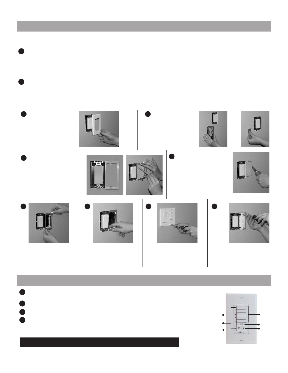
Locate an existing light switch
1
and remove wall plate exposing
electrical box.
Somfy recommends shutting off
power to the exposed electrical
box prior to installation.
NOTE: If not installing keypad with an existing
switch, skip to step 2.
Place the flat side of mounting bracket
3
(included) against the wall and align
the thin side over the outside edge of
the existing electrical box (opposite
the stud side). Center the bracket to
align the mounting screw height with
existing switch, then trace the inside
shape of the bracket on wall using a
pencil or thin marker.
5
Insert bracket (as shown) into hole,
keeping the thin side closest to the
edge of the existing switch box.
*Hole dimensions for (Step 4) mounting bracket (1 5/8” W x 3 7/16” L)
Thin side outer edge of box
Align screw holes
6
Carefully bend bracket tabs 90
degrees behind the dry-wall to
ensure a tight secure fit.
Using a stud sensor, locate
2
the stud nearest to exposed
electrical box. Then mark (for
reference) with removable
tape or pencil.
Using a dry-wall saw (or similar) begin
4
to cut the drywall along the traced
outline. Do not cut hole larger than
outline as this may result in a loose
fitting bracket.
*For greater accuracy please refer to the
recommended hole dimensions on reverse
page.
7
Position the DecoFlex switch into
mounting bracket aligning the screw
holes. Secure switch to mounting
bracket with screws (provided).
8
Attach a new (2 gang) or double gang
Decora style wall plate over both
switches to complete installation.
OPERATION
Select the CONTROL BUTTON(s) programmed to a specific window covering(s). The adjacent LEDs will illuminate to
1
indicate the CONTROL BUTTON selected.
2
To raise the window covering(s), press the UP button. To lower the window covering(s), press the DOWN button.
To stop the window covering(s) at any time, simply press the STOP button (see figure 2).
3
For RTS and SDN keypads programmed to use group function, select a control button followed by an action
4
(default: up, stop and down).
For detailed product operation information, refer to the product programming instructions.
NOTE: Keypads require programming in order to operate as intended.
SAVE THESE INSTRUCTIONS FOR FUTURE REFERENCE
P-0035
Figure 2.
LED
Indicators
RTS Programming
Button (RTS only)
Down
Button
© Copyright 1/2019 SOMFY SYSTEMS, LLC.
Control
Buttons
Stop Button
Up Button
 Loading...