

Sokkia Axis 3 Operation Manual

GPS Receiver System
Axis
3
TM
Operations Manual
Part Number 750-1-0060 Rev 2

Copyright Notice
Copyright © 2000 POINT, Inc. All rights reserved.
No part of this publication or the equipment described in it may be
reproduced, translated, stored in a retrieval system, or transmitted in any
form or by any means, electronic, mechanical photocopying, recording, or
otherwise, without prior written permission of POINT, Inc. Y our rights with
regard to this publication and the equipment are subject to the restrictions
and limitations imposed by the copyright laws of the United States of
America (“U.S.A.”) and/or the jurisdiction in which you are located.
Trademark No tice
Sokkia is a trademark of Sokkia Co. Ltd.
All other product and brand names ar e tradema rks or re gistered trademarks
of their respective holders.
FCC Notice
The equipment described in this manual has been tested pursuant to Part 15
of the FCC Rules and found to comply with the limits for a Class A digital
device for use in commercial business, and industrial environments.
Operation is subject to the following two condit ions: (1) this device may not
cause harmful interfe r en c e, and (2) th is devi ce must acc ept any interference
received, including interference that may cause undesired operation. These
limits are designed to provide reasonable protection against harmful
interference when the equipment is operated in a commercial environment.
The equipment generates, uses, and can radiate radio frequency energy and,
if not installed and used in accordance with the instruction manual, may
cause harmful interference to radio and television reception. Operation of
this equipment in a residential area is likely to cause harmful interference in
which case the user will be required to correct the interference at his own
expense.
If this equipment does cause interference to radio or television reception,
which can be determin ed by tur ning the equipment of f a nd on, you ca n try t o
correct the interference by one or more of the following measures:
• Reorient the receiving antenna.
• Relocate the receiver relative to the equipment which it interferes.
• Power the equipment from a different AC receptacle so that this
equipment and the interfered equipment are on differ ent branch cir cuits.
If necessary, contact our customer service department or an authorized
representative for additional advice.
750-1-006 0 Rev 2 October 16, 2000
POINT, Inc.—Advanced Measurement Solutions from Sokkia and NovAtel

Contents
Chapter 1 Welcome................................................... 1
1.1 Ports and Icons............................................................... 1
1.2 Notes, Cautions, and Warnings................................... 1
1.3 Obtaining Technical Support ....................................... 2
Chapter 2 Introduction.............................................. 5
2.1 Understanding GPS....................................................... 5
2.1.1 How it Works ...................................................... 5
2.1.2 GPS Services ........................................... ............. 6
2.1.3 DGPS Format, GPS Standard............................ 6
2.2 Differential GPS.............................................................. 7
2.2.1 How it Works ...................................................... 7
2.2.2 Real-Time DGPS.................................................. 7
2.3 OmniSTAR Worldwide DGPS Service ....................... 7
2.3.1 OmniSTAR signal information......................... 8
2.3.2 OmniSTAR Reception and DGPS..................... 8
2.3.2.1 Activating the OmniSTAR Service.............9
2.3.2.2 Over-Air Subscription Activation.............10
2.4 Radio Beacon Service........................................ ...... ..... 11
2.4.1 Radiobeacon Range .......................................... 11
2.4.2 Radiobeacon Messages..................................... 12
2.4.3 Radiobeacon Coverage..................................... 13
2.5 Radio Beacon Position Accuracy............................... 14
2.5.1 Proximity............................................................ 14
2.5.2 Latency ............................................................... 15
2.5.3 Ionospheric Errors ............................................ 15
2.5.4 Satellites Visible ................................................ 16
2.5.5 MultiPath ........................................................... 16
2.6 Using WAAS................................................................. 16
Axis
3
i

Contents
2.6.1 Wide Area Augmentation System .....................
(WAAS)16
2.6.2 WAAS reception and DGPS ............................17
3
2.7 Axis
2.8 Axis
Receiver..............................................................17
3
Antenna..............................................................18
Chapter 3 Receiver Set Up......................................19
3.1 Receiver Layout and Connections.............................19
3.1.1 Connecting Cables ............................................20
3.1.2 Communication.................................................21
3
3.2 Install ing the Axis
3.2.1 Environmental Considerations .......................22
3.2.2 Connecting Power............................................. 22
3
3.3 Axis
Antenna Guidelines..........................................22
Receiver......................................22
3.3.1 Placing Antenna for Optimal Reception........ 23
3.3.2 Routing and Securing the Antenna Cable.....23
3
3.3.3 Connecting the Axis
Antenna.......................24
3.4 Installing the Data Collector.......................................24
3.5 Preparing for Operation..............................................24
Chapter 4 Axis 3 Operation......................................27
4.1 Locating Satellites.........................................................27
4.2 Interpreting LED Indicators........................................28
4.2.1 Other LED Conditions (OmniSTAR)..............29
4.3 Understanding Settings............................................... 29
4.3.1 Default Configuration ......................................30
4.4 Beacon Tune Mode.......................................................30
4.4.1 Using ABS Mode...............................................31
4.4.2 Using Manual Mode......................................... 32
4.5 Beacon Performance - SNR Reading .........................32
4.6 DGPS Performance................................. ...... ................ 33
ii Axis
4.4.1.1 ABS Global Search ......................................31
4.4.1.2 ABS Background Sear ch.............................31
3

Contents
Appendix A Troubleshooting.....................................35
Appendix B Specifications.........................................36
Appendix C Frequently Asked Questions ................41
Axis
3
iii


Chapter 1 Welcome
Welcome to the Axis 3 Operations Manual and congratulations
on purchasing this high performance GPS product from Sokkia.
The purpose of this manual is to familiarize you with the
proper installation, configuration, and operation of your new
3
receiver. The Axis
receiver with flexible real-time solutions. This integrated
product is designed to provide positioning by using corrections
from its internal beacon, differential satellite and W AAS sensors
to function in a wide array of applications and environments.
Compact, lightweight, yet rugged, the Axis
provide you with years of reliable operation.
1.1 Ports and Icons
is a high perf ormance 12-channel GPS
3
receiver will
This icon is the symbol for power and identifies the power
port, which is located on the rear panel of the Axis
receiver. The power port is also referred to in this docu
ment as PWR.
This icon is the symbol for communications and identifies
the communications port, which is located on the rear
panel of the Axis receiver. The communications port is
also referred to in this document as COM.
This icon is the symbol for antenna and identifies the
antenna port, which is located on the rear panel of the
Axis receiver. The antenna port is also referred to in this
document as RF.
1.2 Notes, Cautions, and Warnings
Notes, Cautions, and Warnings stress importan t inform a tio n
Axis
3™
1

Chapter 1 Welcome
regarding the installation, configuration, and operation of the
3
Axis
receiver.
* Note: Notes outline important information of a general
nature.
CAUTION
Cautions inform of possible sources of difficulty or situations that may cause
damage to the product.
WARNING
Warnings inform of situations that may cause you harm.
1.3 Obtaining T echnical Support
When contacting customer support, please ensure the following
information is available: the product mode l, serial number and
a concise description of the problem.
2Axis
3™

Welcome Chapter 1
Canada
Sokkia Corp.
1050 Stacey Court
Mississauga, Ontari o
L4W 2X8
Phone +1-905-238 -5810
Fax +1-905-238-9383
Australia
Sokkia Pty. Ltd.
Rydalmere Metro Centre
Unit 29,38-46 South Street
Rydalmere NSW 2116
Australia
Phone +61-2-9638 -0055
Fax +61-2-9638-3933
U.K.
Sokkia Ltd.
Datum House, Electra Way
Crewe Business Park
Crewe, Cheshire, CW1 6ZT
United Kingdom
Phone +44-1270-2 5.0 5. 11
Fax +44-1270-25.05.33
USA
Sokkia Corporation
16900 W. 118th Terrace
P.O. Box 726
Olathe, KS 66061
Phone +1(913) 492-4 900
Fax +1(913) 492-0188
Asia
Sokkia Singapore Pte. Ltd.
401 Commonwealth Dr ive
#06-01 Haw Par Technocentre
Singapore 149598
Phone +65-479-3966
Fax +65-479-4966
Africa
Sokkia RSA Pty. Ltd.
P.O. Box 7998
Centurion, 0046
Republic of South Africa
Phone +27-12-663 -7999
Fax +27-12-663-7998
Europe
Sokkia B.V.
Businesspark De Vaart
Damsluisw eg 1, 1332 EA Almere
P.O. Box 1292, 1300 BG Al mere
The Netherlands
Phone +31-36-53.22. 880
Fax +31-36-53.26.241
New Zealand
Sokkia New Zealand
20 Constellation Drive
Mairangi Bay, C.P.O. Box 4464,
Auckland 10
New Zealand
Phone +64-9-479-3 064
Fax +64-9-479-3066
Central & South America
Sokkia Central & South America
1200 N.W. 78 Avenue
Suite 109
Miami, FL
USA 33126
Phone +1-305-599 -4701
Fax +1-305-599-4703
3™
Axis
3


Welcome Chapter 1
3™
Axis
5

Chapter 2 Introduction
This chapter provides a brief overview of the Global
Positioning System (GPS), differential GPS (DGP S), bea con and
satellite differential and a description of th e Axis
antenna, and accessories.
2.1 Understanding GPS
The United States Department of Defense (DoD) operates a
reliable, 24 hour, all-weather GPS.
Navstar , the original name given to this geographic positioning
and navigation tool, in clud es a constellation of 24 satellites
(plus active spares) orbiting the Earth at an altitude of
3
receiver,
approximately 22,000 km.
* Note: Selective Availability, SA, was turned off in May 2000.
The ini t ial intent of the Dep a rtment of Defense wa s t o have
the ability to degrade the quality of the GPS signal for all
non-military users. The resulting positioning accuracy with
SA on is from a few meters to 100 meters, however with SA
off the positioning accuracy is approxima tely two to five
meters. If there is an immediate danger perceived to the
USA, SA may be turned on without review.
2.1.1 How it Works
GPS satellites transmit cod e d i nf ormation to GPS users at UHF
(1.575 GHz) frequencies that allows user equipment to calculate
a range to each satellite. GPS is essentially a timing system ranges are calculated by timing how long it takes for the GPS
signal to reach the user’s GPS antenna.
Axis
3™
5

Chapter 2 Introduction
To calculate a geographic position, the GPS receiver uses a
complex algorithm incorporating satellite coordinates a nd
ranges to each satellite. Reception of any four or more of these
signals allows a GPS receiver to compute 3D coordinates.
Tracking of only three satellites reduces the positio n f ix to 2 D
coordinates (horizontal with fixed vertical).
2.1.2 GPS Services
The positioning accuracy offered by GPS varies depending
upon the type of service and equipment available. For security
reasons, two GPS services exist: the Standard Positioning
Service (SPS) and the Precise Positioning Service (PPS). The US
DoD reserves the PPS for use by its personnel and authorized
partners. The DoD provides the SPS free of charge, worldwide,
to all civilian users.
For many positioning and navigation applications, stand-alone
or autonomous accuracy i s insufficient, and differential
positioning techniques must be employed.
2.1.3 DGPS Format, GPS Standard
For manufacturers of GPS equipment, commonality is essential
to maximize the utility and compa tibility of a product. The
governing standard associated with GPS is the Interface
Control Document, ICD-GPS-200, maintained by the US DoD.
This document provides the message and signal structure
information required to access GPS.
Like GPS, DGPS data and broadcast standards exist to ensure
compatibility between DGPS networks and associa ted
hardw are and soft ware. The Radio Technical Commission for
Maritime Services Special Committee 104 has developed the
primary DGPS standard associated with radiobeacon DGPS,
designated RTCM SC-104 V2.2.
6Axis
3™

Introduction Ch apte r 2
2.2 Differential GPS
The purpose of DGPS is to remove the effects of atmospheric
errors, timing errors, and satellite orbit errors, while enhancing
system integrity.
2.2.1 How it Works
DGPS involves setting up a reference GPS receiver at a point of
known coordinates. This receiver makes distance
measurements, in real-time, to each of the GPS satellites. The
measured ranges include the erro rs present in the system. The
base station receiver calculates what the true range should be,
without errors, knowing its coordinates and those of each
satellite. The difference between the known and measured
range for each satellite is the range error. This error is the
amount that needs to be removed from each sa tellite distance
measurement in order to correct for errors present in the
system.
2.2.2 Real-Time DGPS
The base station transmits the range error corrections to remote
receivers in real-time. The remote receiver corrects its satellite
range measurements using these differential corrections,
yielding a much more accurate position. This is the
predominant DGPS strategy used for a majority of real-time
applications. Positi oning using corrections generated by DGPS
radiobeacons will provide a horizontal accuracy of one to five
meters with a 95% confidence.
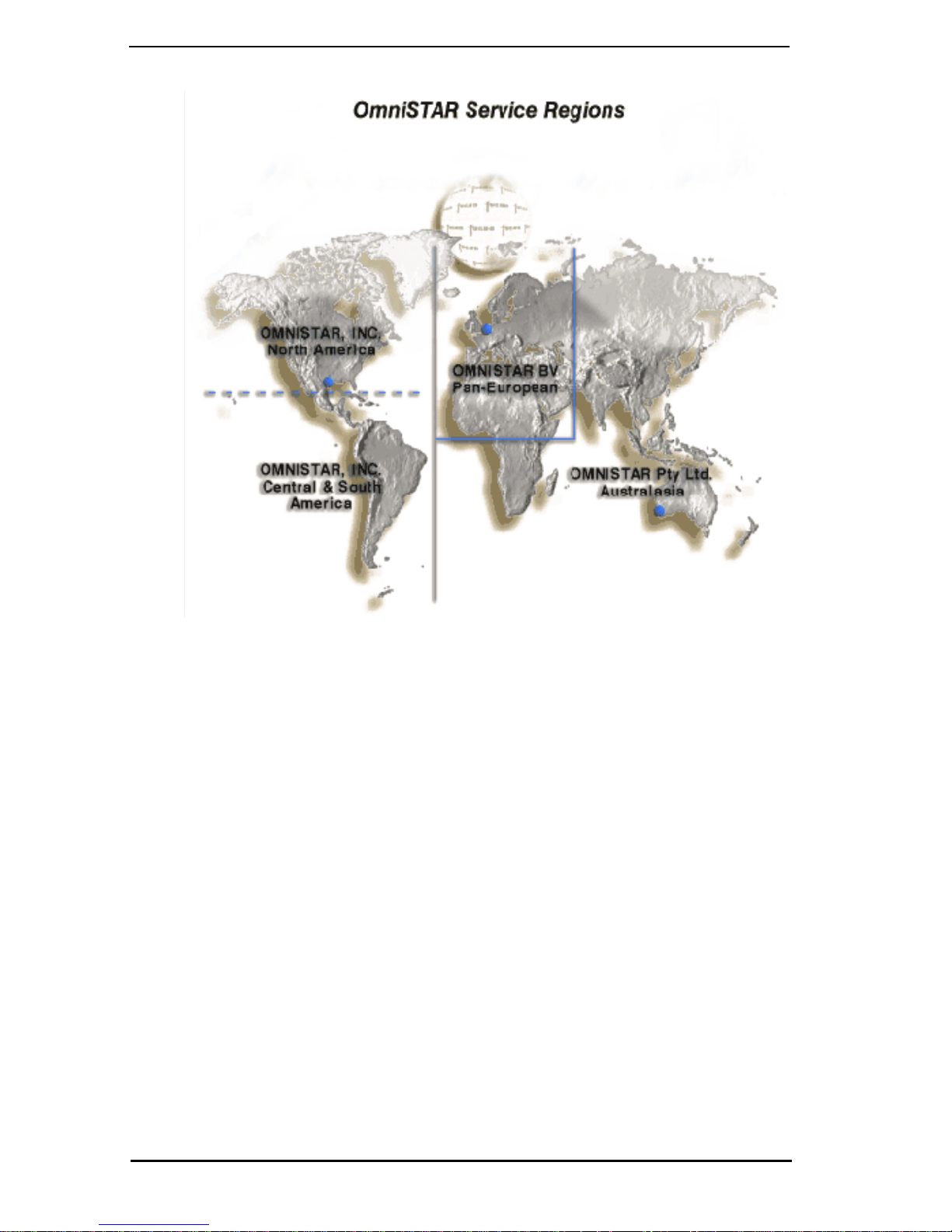
2.3 OmniSTAR Worldwide DGPS Service
OmniST AR
DGPS corrections to subscribers of the system through a
geostationary satellite signal.
3™
Axis
TM
is a worldwide terrestrial service that provides
7

Chapter 2 Introduction
2.3.1 OmniSTAR signal information
The OmniST AR satellite correction is a line-of-sight UHF signal
similar to the GPS sig nal. Various L-Band communication s
satellites are used for transmitting the correction data to
OmniSTAR users around the world. The OmniSTAR signal can
be used where beacon signals are not available.
The OmniSTAR service uses geostationary satellites (satellites
that remain stationary in relation to the earth) for
communication. The elevation angle to these satellites is
dependent upon latitude. OmniSTAR provides differential
coverage over most of the land areas of the globe, with the
exception of some areas beyond 60 degrees South Latitude.
However, even within the coverage areas, the user must have a
clear line-of-sight to the satelli te.
2.3.2 OmniSTAR Reception and DGPS
The OmniSTAR network functions as a wide-area DGPS
service. The information broadcast by the service is based on a
network of strategic reference stations. The reference stat ions
communicate GPS correction data to control centers where it is
decoded, checked, and repacka ged into a proprietar y format for
transmission to a geostationary L-ba nd communications
satellite. This correction data is rebroadcast to the Earth over a
large area where an L-band differential receiver demodulates
the data.
3
The Axis
signal specific to your location . The resultin g corrections are
similar to those calculated if a reference station was set up at
receiver will process corrections from the wi de-area
your location. This type of solution ensures a consistent level of
accuracy across the entire coverage area.
The OmniSTAR signal is a proprietary wide-area signal (not
RTCM SC-104) with specialized geographically independent
formats. Positioning accuracy will not degrade based on the
distance to a base station. The data is composed of information
8Axis
3™

Introduction Ch apte r 2
from an entire network as opposed to a single base station.
When the signal is demodulated by a DGPS receiver, it is
converted to a local-area format (standard RTCM SC-104,
message Type 1) for input.
3
The Axis
L-Band receiver uses a feature called a Virtual Base
Station (VBS) when processing the OmniSTAR wide-area
signal. The resulting corrections are those th at woul d be
applied if a reference station were set up at your present
location. This provides consistent accuracy levels across the
coverage area.
* Note: The GPS receiver inside the Axis
3
provides position
information to the L-Band receiver for VBS calculations.
2.3.2.1 Activating the OmniSTAR Service
To use OmniSTAR, you must know your receiver’s internal Lband receiver number. This number can be found on the silver
tag located on the bottom of the receiver.
You can contact the OmniST AR of fice closest to your location to
receive a subscription.
Location Phone Number Fax Number
North America +1-888-883-8476 +1-713-780-9408
Europe/North America +31-70-311-1151 +31-71-581-4719
Asia, Australia, New
Zealand, South Africa
Central American,
South America
3™
Axis
+61-89-322-5295 +61-8-9322-4164
+1-713-785-5850 +1-713-780-9408
9
Chapter 2 Introduction
2.3.2.2 Over-Air Subscription Activation
After you contact OmniSTAR, your subscription can be
3
activated on your Axis
receiver over the air. The internal
DGPS receiver will automatically lock on to the signal even if
your subscription has not been ac tivated, however it is of no
use to you until your subscription is activated.
When you power on the receiver, you must have the antenna in
a location with an unobstructed view of the sky. The
subscription activation will be transmitted over the air and
received by the internal L-band DGPS receiver.
To confirm you have a valid and active OmniSTAR
subscription, refer to your data collection software reference
manual.
10 Axis
3™
 Loading...