

Sokkia Atlas Operator's Manual

Sokkia Atlas
GNSS Receiver
Operator’s Manual
All contents in this manual are copyrighted by Sokkia. All rights reserved.
Part Number 1006148-01
Rev C
©Copyright Sokkia
March, 2016

• • • • • •
Table of Contents
Table of Contents
Preface . . . . . . . . . . . . . . . . . . . . . . . . . . . . . . . . . . . . . . . . . . . . . . . . . . . . . . . . . . . . . . . . . . . . . . iv
Terms and Conditions . . . . . . . . . . . . . . . . . . . . . . . . . . . . . . . . . . . . . . . . . . . . . . . . . . . . . . . . . iv
Use . . . . . . . . . . . . . . . . . . . . . . . . . . . . . . . . . . . . . . . . . . . . . . . . . . . . . . . . . . . . . . . . . . .iv
Copyrights . . . . . . . . . . . . . . . . . . . . . . . . . . . . . . . . . . . . . . . . . . . . . . . . . . . . . . . . . . . . . . iv
Trademarks . . . . . . . . . . . . . . . . . . . . . . . . . . . . . . . . . . . . . . . . . . . . . . . . . . . . . . . . . . . . .iv
Disclaimer of Warranty . . . . . . . . . . . . . . . . . . . . . . . . . . . . . . . . . . . . . . . . . . . . . . . . . . . . .iv
License Agreement . . . . . . . . . . . . . . . . . . . . . . . . . . . . . . . . . . . . . . . . . . . . . . . . . . . . . . . .v
Confidentiality. . . . . . . . . . . . . . . . . . . . . . . . . . . . . . . . . . . . . . . . . . . . . . . . . . . . . . . . . . . . v
Website; Other Statements . . . . . . . . . . . . . . . . . . . . . . . . . . . . . . . . . . . . . . . . . . . . . . . . . . v
Safety . . . . . . . . . . . . . . . . . . . . . . . . . . . . . . . . . . . . . . . . . . . . . . . . . . . . . . . . . . . . . . . . .v
Miscellaneous . . . . . . . . . . . . . . . . . . . . . . . . . . . . . . . . . . . . . . . . . . . . . . . . . . . . . . . . . . . .v
Manual Conventions . . . . . . . . . . . . . . . . . . . . . . . . . . . . . . . . . . . . . . . . . . . . . . . . . . . . . . . . . .vi
Introduction . . . . . . . . . . . . . . . . . . . . . . . . . . . . . . . . . . . . . . . . . . . . . . . . . . . . . . . . . . . . . . . . . . 1
Sokkia Atlas Features . . . . . . . . . . . . . . . . . . . . . . . . . . . . . . . . . . . . . . . . . . . . . . . . . . . . . . . . .1
Unpacking Your Receiver Kit . . . . . . . . . . . . . . . . . . . . . . . . . . . . . . . . . . . . . . . . . . . . . . . . . . . .1
Standard Kit Components . . . . . . . . . . . . . . . . . . . . . . . . . . . . . . . . . . . . . . . . . . . . . . . . . . . 2
Accessories. . . . . . . . . . . . . . . . . . . . . . . . . . . . . . . . . . . . . . . . . . . . . . . . . . . . . . . . . . . . . . 2
Using Sokkia Software With Your Receive r. . . . . . . . . . . . . . . . . . . . . . . . . . . . . . . . . . . . . . . . . . . 3
Getting Technical Support . . . . . . . . . . . . . . . . . . . . . . . . . . . . . . . . . . . . . . . . . . . . . . . . . . . . . . 3
Website . . . . . . . . . . . . . . . . . . . . . . . . . . . . . . . . . . . . . . . . . . . . . . . . . . . . . . . . . . . . . . . . 3
Getting Acquainted. . . . . . . . . . . . . . . . . . . . . . . . . . . . . . . . . . . . . . . . . . . . . . . . . . . . . . . . . . . . . 4
Receiver Overview. . . . . . . . . . . . . . . . . . . . . . . . . . . . . . . . . . . . . . . . . . . . . . . . . . . . . . . . . . . .4
Cables . . . . . . . . . . . . . . . . . . . . . . . . . . . . . . . . . . . . . . . . . . . . . . . . . . . . . . . . . . . . . . . . . . . .5
Accessories. . . . . . . . . . . . . . . . . . . . . . . . . . . . . . . . . . . . . . . . . . . . . . . . . . . . . . . . . . . . . . . . .6
Batteries . . . . . . . . . . . . . . . . . . . . . . . . . . . . . . . . . . . . . . . . . . . . . . . . . . . . . . . . . . . . . . . . . . 7
Data and Power Ports . . . . . . . . . . . . . . . . . . . . . . . . . . . . . . . . . . . . . . . . . . . . . . . . . . . . . . . . .7
External Radio Antenna Connector . . . . . . . . . . . . . . . . . . . . . . . . . . . . . . . . . . . . . . . . . . . . . . . .8
Bottom Connector. . . . . . . . . . . . . . . . . . . . . . . . . . . . . . . . . . . . . . . . . . . . . . . . . . . . . . . . . . . . 9
SD/SDHC and SIM Card Slots . . . . . . . . . . . . . . . . . . . . . . . . . . . . . . . . . . . . . . . . . . . . . . . . . . . .9
SIM Card Slot . . . . . . . . . . . . . . . . . . . . . . . . . . . . . . . . . . . . . . . . . . . . . . . . . . . . . . . . . . . .10
SIM Cards . . . . . . . . . . . . . . . . . . . . . . . . . . . . . . . . . . . . . . . . . . . . . . . . . . . . . 10
Installing the SIM Card. . . . . . . . . . . . . . . . . . . . . . . . . . . . . . . . . . . . . . . . . . . . 10
Display Panel Operations. . . . . . . . . . . . . . . . . . . . . . . . . . . . . . . . . . . . . . . . . . . . . . . . . . . . . . . . 11
Power Button . . . . . . . . . . . . . . . . . . . . . . . . . . . . . . . . . . . . . . . . . . . . . . . . . . . . . . . . . . . . . . .11
Receiver Status LEDs. . . . . . . . . . . . . . . . . . . . . . . . . . . . . . . . . . . . . . . . . . . . . . . . . . . . . . . . . . 11
STAT LED. . . . . . . . . . . . . . . . . . . . . . . . . . . . . . . . . . . . . . . . . . . . . . . . . . . . . . . . . . . . . . .12
REC LED. . . . . . . . . . . . . . . . . . . . . . . . . . . . . . . . . . . . . . . . . . . . . . . . . . . . . . . . . . . . . . . .12
RX TX LED . . . . . . . . . . . . . . . . . . . . . . . . . . . . . . . . . . . . . . . . . . . . . . . . . . . . . . . . . . . . . . 12
Table of Contents
P/N: 1006148-01
i

Bluetooth LED. . . . . . . . . . . . . . . . . . . . . . . . . . . . . . . . . . . . . . . . . . . . . . . . . . . . . . . . . . . . 13
Battery LED . . . . . . . . . . . . . . . . . . . . . . . . . . . . . . . . . . . . . . . . . . . . . . . . . . . . . . . . . . . . . . . .13
FUNCTION Button/Logging Data. . . . . . . . . . . . . . . . . . . . . . . . . . . . . . . . . . . . . . . . . . . . . . . . . .14
Managing Power. . . . . . . . . . . . . . . . . . . . . . . . . . . . . . . . . . . . . . . . . . . . . . . . . . . . . . . . . . . . . . . 16
Turning On/Off the Receiver . . . . . . . . . . . . . . . . . . . . . . . . . . . . . . . . . . . . . . . . . . . . . . . . . . . .16
Powering the Receiver. . . . . . . . . . . . . . . . . . . . . . . . . . . . . . . . . . . . . . . . . . . . . . . . . . . . . . . . . 16
Detachable External Batteries. . . . . . . . . . . . . . . . . . . . . . . . . . . . . . . . . . . . . . . . . . . . . . . . . 16
Charging the Batteries . . . . . . . . . . . . . . . . . . . . . . . . . . . . . . . . . . . . . . . . . . . . 16
Battery Charging Temperatures. . . . . . . . . . . . . . . . . . . . . . . . . . . . . . . . . . . . . . 18
Charging Procedure . . . . . . . . . . . . . . . . . . . . . . . . . . . . . . . . . . . . . . . . . . . . . . 18
Leaving the Batteries on Charge . . . . . . . . . . . . . . . . . . . . . . . . . . . . . . . . . . . . . 18
Attaching the Batteries. . . . . . . . . . . . . . . . . . . . . . . . . . . . . . . . . . . . . . . . . . . . 19
Detaching the Batteries . . . . . . . . . . . . . . . . . . . . . . . . . . . . . . . . . . . . . . . . . . . 19
Surveying While Charging. . . . . . . . . . . . . . . . . . . . . . . . . . . . . . . . . . . . . . . . . . 19
Changing the Batteries while Surveying . . . . . . . . . . . . . . . . . . . . . . . . . . . . . . . . 19
Using an Auxiliary Power Source. . . . . . . . . . . . . . . . . . . . . . . . . . . . . . . . . . . . . . . . . . . . . . .20
Insufficient Power . . . . . . . . . . . . . . . . . . . . . . . . . . . . . . . . . . . . . . . . . . . . . . . . . . . . . . . . . . . .21
Configuring the Receiver . . . . . . . . . . . . . . . . . . . . . . . . . . . . . . . . . . . . . . . . . . . . . . . . . . . . . . . . 22
Viewing Receiver Information. . . . . . . . . . . . . . . . . . . . . . . . . . . . . . . . . . . . . . . . . . . . . . . . . . . . 22
Loading New Firmware . . . . . . . . . . . . . . . . . . . . . . . . . . . . . . . . . . . . . . . . . . . . . . . . . . . . . . . .23
About the OAF . . . . . . . . . . . . . . . . . . . . . . . . . . . . . . . . . . . . . . . . . . . . . . . . . . . . . . . . . . . . . .25
Checking the Receiver’s OAF . . . . . . . . . . . . . . . . . . . . . . . . . . . . . . . . . . . . . . . . . . . . . . . . . 25
Loading an OAF . . . . . . . . . . . . . . . . . . . . . . . . . . . . . . . . . . . . . . . . . . . . . . . . . . . . . . . . . . 26
Performing a Factory Reset . . . . . . . . . . . . . . . . . . . . . . . . . . . . . . . . . . . . . . . . . . . . . . . . . . . . . 30
Field System Setup. . . . . . . . . . . . . . . . . . . . . . . . . . . . . . . . . . . . . . . . . . . . . . . . . . . . . . . . . . . . . 32
Setting Up the Base Receiver . . . . . . . . . . . . . . . . . . . . . . . . . . . . . . . . . . . . . . . . . . . . . . . . . . . . 32
Setting Up the Rover Receiver . . . . . . . . . . . . . . . . . . . . . . . . . . . . . . . . . . . . . . . . . . . . . . . . . . .3 3
Measuring Antenna Height. . . . . . . . . . . . . . . . . . . . . . . . . . . . . . . . . . . . . . . . . . . . . . . . . . . . . . 33
Collecting Data . . . . . . . . . . . . . . . . . . . . . . . . . . . . . . . . . . . . . . . . . . . . . . . . . . . . . . . . . . . . . . . . 35
Memory . . . . . . . . . . . . . . . . . . . . . . . . . . . . . . . . . . . . . . . . . . . . . . . . . . . . . . . . . . . . . . . . . . .35
SD/SDHC Card . . . . . . . . . . . . . . . . . . . . . . . . . . . . . . . . . . . . . . . . . . . . . . . . . . . . . . . . . . . 35
Installing the SD/SDHC Card. . . . . . . . . . . . . . . . . . . . . . . . . . . . . . . . . . . . . . . . 35
Initializing the File System . . . . . . . . . . . . . . . . . . . . . . . . . . . . . . . . . . . . . . . . . . . . . . . . . . .35
Initializing the File System Using SRU . . . . . . . . . . . . . . . . . . . . . . . . . . . . . . . . . 36
Setting Recording Parameters . . . . . . . . . . . . . . . . . . . . . . . . . . . . . . . . . . . . . . . . . . . . . . . . . . . 36
Logging Rates . . . . . . . . . . . . . . . . . . . . . . . . . . . . . . . . . . . . . . . . . . . . . . . . . . . . . . . . . . . . . . . 36
Recording Data. . . . . . . . . . . . . . . . . . . . . . . . . . . . . . . . . . . . . . . . . . . . . . . . . . . . . . . . . . . . . .36
Managing Files . . . . . . . . . . . . . . . . . . . . . . . . . . . . . . . . . . . . . . . . . . . . . . . . . . . . . . . . . . . . . .37
Downloading and Deleting Files . . . . . . . . . . . . . . . . . . . . . . . . . . . . . . . . . . . . . . . . . . . . . . . 37
Troubleshooting . . . . . . . . . . . . . . . . . . . . . . . . . . . . . . . . . . . . . . . . . . . . . . . . . . . . . . . . . . . . . . . 38
Check This First! . . . . . . . . . . . . . . . . . . . . . . . . . . . . . . . . . . . . . . . . . . . . . . . . . . . . . . . . . . . . .38
Powering Problems . . . . . . . . . . . . . . . . . . . . . . . . . . . . . . . . . . . . . . . . . . . . . . . . . . . . . . . . . . . 38
Table of Contents
P/N: 1006148-01
ii

Receiver Problems. . . . . . . . . . . . . . . . . . . . . . . . . . . . . . . . . . . . . . . . . . . . . . . . . . . . . . . . . . . .39
Bluetooth Problems. . . . . . . . . . . . . . . . . . . . . . . . . . . . . . . . . . . . . . . . . . . . . . . . . . . . . . . . . . .41
SRU Problems. . . . . . . . . . . . . . . . . . . . . . . . . . . . . . . . . . . . . . . . . . . . . . . . . . . . . . . . . . . . . . .42
Cleaning and Storing the Receiver . . . . . . . . . . . . . . . . . . . . . . . . . . . . . . . . . . . . . . . . . . . . . . . .42
Getting Customer Support . . . . . . . . . . . . . . . . . . . . . . . . . . . . . . . . . . . . . . . . . . . . . . . . . . . . . .42
Specifications . . . . . . . . . . . . . . . . . . . . . . . . . . . . . . . . . . . . . . . . . . . . . . . . . . . . . . . . . . . . . . . . . 43
General Details . . . . . . . . . . . . . . . . . . . . . . . . . . . . . . . . . . . . . . . . . . . . . . . . . . . . . . . . . . . . . . 43
Digital UHF II Internal Modem Board Details (Optional) . . . . . . . . . . . . . . . . . . . . . . . . . . . . . . . . . 48
Optional Cell Module Details. . . . . . . . . . . . . . . . . . . . . . . . . . . . . . . . . . . . . . . . . . . . . . . . . . . . .49
Bluetooth Module Details . . . . . . . . . . . . . . . . . . . . . . . . . . . . . . . . . . . . . . . . . . . . . . . . . . . . . . . 50
Connector Specifications . . . . . . . . . . . . . . . . . . . . . . . . . . . . . . . . . . . . . . . . . . . . . . . . . . . . . . . 50
Radio (Modem) RF Connector. . . . . . . . . . . . . . . . . . . . . . . . . . . . . . . . . . . . . . . . . . . . . . . . .50
Power Connector. . . . . . . . . . . . . . . . . . . . . . . . . . . . . . . . . . . . . . . . . . . . . . . . . . . . . . . . . . 51
Serial C-RS232 Connector . . . . . . . . . . . . . . . . . . . . . . . . . . . . . . . . . . . . . . . . . . . . . . . . . . . 52
USB Connector . . . . . . . . . . . . . . . . . . . . . . . . . . . . . . . . . . . . . . . . . . . . . . . . . . . . . . . . . . . 53
Product Identification . . . . . . . . . . . . . . . . . . . . . . . . . . . . . . . . . . . . . . . . . . . . . . . . . . . . . . . . . . 54
SD/SDHC Card Recommendations . . . . . . . . . . . . . . . . . . . . . . . . . . . . . . . . . . . . . . . . . . . . . . . . 55
Safety Warnings . . . . . . . . . . . . . . . . . . . . . . . . . . . . . . . . . . . . . . . . . . . . . . . . . . . . . . . . . . . . . . . 56
General Warnings . . . . . . . . . . . . . . . . . . . . . . . . . . . . . . . . . . . . . . . . . . . . . . . . . . . . . . . . . . . .56
Battery Warnings . . . . . . . . . . . . . . . . . . . . . . . . . . . . . . . . . . . . . . . . . . . . . . . . . . . . . . . . . . . .56
Receiver Warnings . . . . . . . . . . . . . . . . . . . . . . . . . . . . . . . . . . . . . . . . . . . . . . . . . . . . . . . . . . . 56
Usage Warnings . . . . . . . . . . . . . . . . . . . . . . . . . . . . . . . . . . . . . . . . . . . . . . . . . . . . . . . . . . . . 56
Regulatory . . . . . . . . . . . . . . . . . . . . . . . . . . . . . . . . . . . . . . . . . . . . . . . . . . . . . . . . . . . . . . . . . . . 57
FCC Compliance . . . . . . . . . . . . . . . . . . . . . . . . . . . . . . . . . . . . . . . . . . . . . . . . . . . . . . . . . . . . .57
Industry Canada Compliance . . . . . . . . . . . . . . . . . . . . . . . . . . . . . . . . . . . . . . . . . . . . . . . . . . . . 57
IC RF Radiation Exposure Statement. . . . . . . . . . . . . . . . . . . . . . . . . . . . . . . . . . . . . . . . . . . . 5 7
IC Additional Statement with Detachable Antennas. . . . . . . . . . . . . . . . . . . . . . . . . . . . . . . . . .58
Community of Europe Compliance . . . . . . . . . . . . . . . . . . . . . . . . . . . . . . . . . . . . . . . . . . . . . . . . 58
European Community Declaration of Conformity with R&TTE Directive 1999/5/EC. . . . . . . . . . . . 58
Declaration of Conformity (R&TTE Directive 1999/5/EC) . . . . . . . . . . . . . . . . . . . . . . . . . . . . . . . . . 59
WEEE Directive. . . . . . . . . . . . . . . . . . . . . . . . . . . . . . . . . . . . . . . . . . . . . . . . . . . . . . . . . . . . . . 60
Bluetooth Transmission Statements/Compliance. . . . . . . . . . . . . . . . . . . . . . . . . . . . . . . . . . . . . . . 61
Warranty. . . . . . . . . . . . . . . . . . . . . . . . . . . . . . . . . . . . . . . . . . . . . . . . . . . . . . . . . . . . . . . . . . . . . 62
Glossary . . . . . . . . . . . . . . . . . . . . . . . . . . . . . . . . . . . . . . . . . . . . . . . . . . . . . . . . . . . . . . . . . . . . . 63
Table of Contents
P/N: 1006148-01
iii
• • • • • •
Preface
Thank you for purchasing this Sokkia product. The materials available in this Manual (the “Manual”) have been
prepared by Topcon Positioning Systems, Inc. (“TPS”) for owners of Sokkia products, and are designed to assist
owners with the use of the receiver and its use is subject to these terms and conditions (the “Terms and
Conditions”).
Please read the terms and conditions carefully.
Terms and Conditions
Use
This product is designed to be used by a professional. The user should have a good knowledge of the safe use of
the product and implement the types of safety procedures recommended by the local government protection
agency for both private use and commercial job sites.
Copyrights
All information contained in this Manual is the intellectual property of , and cop yrighted material of TPS. All rights
are reserved. Do not use, access, copy, store, display, create derivative works of, sell, modif y, publish, distribute,
or allow any third party access to, an y graphics, co ntent, informat ion or data in this Manual w ithout TPS’ expre ss
written consent and may only use such information for the care and operation of the receiver. The information
and data in this Manual are a valuable asset of TPS and are developed by the expenditure of consider able wor k,
time and money, and are the result of original selection, coordination and arrangement by TPS.
Trademarks
MAGNET®, Sokkia®, and Topcon® are trademarks or registered trademarks of the Topcon group of companies.
Windows® is a registered trademark of Microsoft Corporation. The Bluetooth® word mark and logos are owned
by Bluetooth SIG, Inc. and any use of such marks by T opcon Positioning Systems, Inc. is used under license. Other
product and company names mentioned herein may be trademarks of their respective owners.
Disclaimer of Warranty
EXCEPT FOR ANY WARRANTIES IN AN APPENDIX OR A WARRANT Y CARD ACCOMPANYING THE PRODUCT, THIS
MANUAL AND THE RECEIVER ARE PROVIDED “AS-IS. ” THER E ARE NO OTHER WARRANTIES. TPS DISCL AIMS ANY
IMPLIED WARRANTY OF MERCHANT ABILIT Y OR FITNESS FOR ANY PARTICUL AR USE OR PURPOSE. TPS AND ITS
DISTRIBUTORS SHALL NOT BE LIABLE FOR TECHNICAL OR EDITORIAL ERRORS OR OMISSIONS CONTAINED
HEREIN; NOR FOR INCIDENTAL OR CONSEQUENTIAL DAMAGES RESULTING FROM THE FURNISHING,
PERFORMANCE OR USE OF THIS MATERIAL OR THE RECEIVER. SUCH DISCL AIMED DAMAGES INCLUDE BUT ARE
NOT LIMITED TO LOSS OF TIME, LOSS OR DESTRUCTION OF DATA, LOSS OF PROFIT, SAVINGS OR REVENUE,
OR LOSS OF THE PRODUCT’S USE. IN ADDITION TPS IS NOT RESPONSIBLE OR LIABLE FOR DAMAGES OR COSTS
INCURRED IN CONNECTION WITH OBTAINING SUBSTITUTE PRODUCTS OR SOFTWARE, CLAIMS BY OTHERS,
INCONVENIENCE, OR ANY OTHER COSTS. IN ANY EVENT, TPS SHALL HAVE NO LIABILITY FOR DAMAGES OR
OTHERWISE TO YOU OR ANY OTHER PERSON OR ENTITY IN EXCESS OF THE PURCHASE PRICE FOR THE
RECEIVER.
Preface
P/N: 1006148-01
iv

License Agreement
Use of any computer programs or software supplied by TPS and Sokkia or downloaded from a Sokkia website
(the “Software”) in connection with the receiver constitutes acceptance of these Terms and Conditions in this
Manual and an agreement to abide by these Terms and Conditions. The user is granted a personal, non-
exclusive, non-transfer able license to use such Software under the terms stated herein and in any case only with
a single receiver or single computer. You may not assign or transfer the Software or this license without the
express written consent of TPS. This license is effective until terminated. You may terminate the license at any
time by destroying the Software and Manual. TPS may terminate the license if you fail to comply with any of
the Terms or Conditions. You agree to destroy the Software and manual upon termination of the use of the
receiver. All ownership, copyright and other intellectual property rights in and to the Software belong to TPS. If
these license terms are not acceptable, return any unused software and manual.
Confidentiality
This Manual, its contents and the Software (collectively , the “Confidential Information”) ar e the confidential and
proprietary information of TPS. You agree to treat TPS’ Confidential Information with a degree of care no less
stringent that the degree of care you would use in safeguarding your own most valuable t rade secrets. Nothing
in this paragraph shall restrict you from disclosing Confidential Information to your employees as may be
necessary or appropriate to operate or care for the receiver . Such employees must also keep the Confidentiality
Information confidential. In the event you become legally compelled to disclose any of the Confidential
Information, you shall give TPS immediate notice so that it may seek a protective order or other appropriate
remedy.
Preface
Website; Other Statements
No statement contained at the TPS and Sokkia websites (or any other website) or in any other advertisements
or TPS literature or made by an employee or independent contractor of TPS modifies these T e rms and Conditions
(including the Software license, warranty and limitation of liability).
Safety
Improper use of the receiver can lead to injury to persons or property and/or malfunction of the product. The
receiver should only be repair ed by authorized TPS warr anty serv ice centers. Users should r eview and heed the
safety warnings in an Appendix.
Miscellaneous
The above T erms and Conditions may be amended, modified, superseded, or canceled, at any time by TPS. The
above Terms and Conditions will be governed by, and construed in accordance with, the laws of the State of
California, without reference to conflict of laws.
Preface
P/N: 1006148-01
v
Manual Conventions
This manual uses the following conventions:
Convention Description Example
Bold Menu, or drop-down menu selection FileExit (Click the File menu and click
Bold
Bold
Mono User supplied text or variable Type guest, and click Enter.
Italic
Further information to note about system configuration, maintenance, or setup.
Supplementary information that can have an adverse affect on system operation, system
performance, data integrity, measurements, or personal safety.
Name of a dialog box or screen From the Connection screen...
Button or key commands Click Finish.
Reference to another manual or help document Refer to the
Preface
Exit)
Sokkia Online Help.
Notification that an action has the potential to result in system damage, loss of data, loss of
warranty, or personal injury.
Preface
P/N: 1006148-01
vi
• • • • • •
Introduction
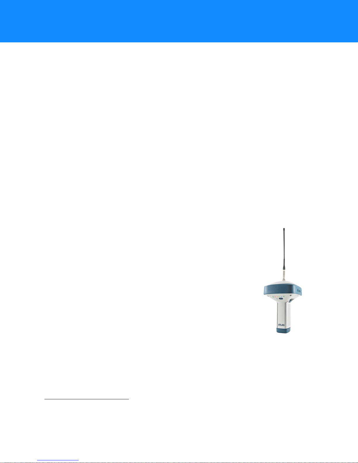
Sokkia’s Atlas receiver is a compact, high-performing, 226 channel GNSS receiver for static and kinematic
applications. The receiver design includes the latest GNSS board technology, which provides optimized satellit e
tracking technology . The Sokkia Atlas delivers world-class positioning and navigation capability to y our application
by tracking signals with multiple frequencies and multi-constellation satellite systems.
Using full-wave antenna technology, the Sokkia Atlas can receiv e and process multiple signal types, including the
latest GPS L2C and L5, Beidou B1, B2, and other future
GNSS receiver board that supports 226 channels with universal tracking technology.
GNSS tracking capabilities, multi-frequency RTK, SBAS functionality, extensive communication capabilities,
removable memory for files combine to provide a positioning system efficient, secure, and appropriate for any
survey.
Several unique features, including adv anced multipath mitigation, adjustable Phase-Locked Loop (LLP) and Delay-
Locked Loop (DLL), offer a reliable and versatile reception of weak signals even in degraded signal environments.
The receiver also supports advanced algorithms for superior GNSS tracking in high-vibration environments.
The Sokkia Atlas offers complete protection against dust and water ingress, in addition to superior vibration and
shock resistance. The Sokkia communication interface allows you to quickly integrate Sokkia’s premium GNSS
performance within new systems and quickly deliver world-class positioning and navigation support to your
applications.
Sokkia Atlas Features
1
signals. The Sokkia Atlas receiver includes an enhanced
The Sokkia Atlas receiver’s advanced design allows for a simplified setup and premium performance. The Sokkia
Atlas receiver features the following:
•
A premier multi-constellation GNSS board
•
Industry leading full-wave antenna technology
•
Detachable batteries for extended operation
•
Internal radio and cellular (optional) modems
•
Integrated Bluetooth® wireless and radio technology
•
Optional HSPA (3.5G)2 cellular technology
•
Interface for controlling viewing data logging through the LED display
•
External power, USB, and serial-data ports
•
External high-capacity memory card support
The Sokkia Atlas is available in the following configurations:
•
Digital UHF II radio modem
•
Digital UHF II radio modem with HSPA module
Unpacking Your Receiver Kit
This section describes the documentation, standard kit components3, and accessories (depending on your
purchase) that accompany your receiver. When you unpack your receiver kit, verify you received the items listed
in this section. If any items are missing or damaged, contact your Sokkia dealer or Sokkia technical support. See
“Getting Technical Support” on page 3.
1. The Sokkia Atlas receiver is equipped with a GNSS board that is Galileo-ready. Full support of this new constellation and associated
signals will be incorporated into the receiver when the constellation is mature, and ready for commercial use.
2. High-Speed Packet Access (HSPA) cellular module supports faster data rate and is backward compatible with GPRS/EDGE (GSM)
technology.
3. Components in standard kits may differ based on your region. Contact your local Sokkia dealer to inquire about items included in your
regional standard kit and accessories that are available with the receiver.
Introduction
P/N: 1006148-01
1
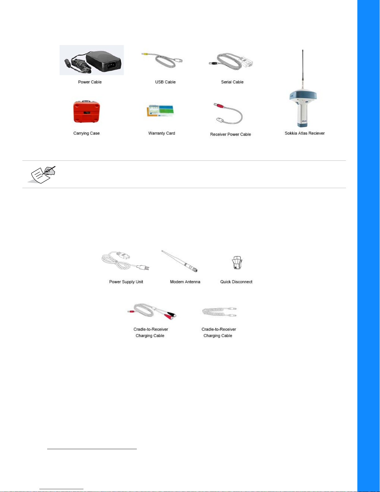
Standard Kit Components1
Figure 1: Standard System Components Included with Your Receiver
The Sokkia Receiver Utility (SRU), USB drivers, and Sokkia Atlas Operator’s Manual are available on
the Sokkia Support website: http://sokkiasupport.com/.
Introduction
Accessories
Sokkia offers a wide variety of accessories (Figure 2) specially designed to improve system flexibility and job
site efficiency . For mor e details on the optional accessories available for Sokkia Atlas, contact your Sokkia dealer.
Figure 2: Receiver Accessories
1. Components in standard kits may differ based on your region. Contact your local Sokkia dealer to inquire about items and
accessories included in your kit.
Unpacking Your Receiver Kit
P/N: 1006148-01
2

Using Sokkia Software With Your Receiver
Use the Sokkia Atlas receiver in conjunction with the Sokkia Receiver Utility (SRU) and MAGNET® Field
applications for a precision positioning solution. Sokkia software enables you to configure the receiver and other
external devices, manage files, collect data, and perform survey and construction work flows.
The Sokkia Receiver Utility (SRU) is a hardware configur ation software for receivers and peripheral devices. You
can install it on desktop computers and data controllers, and is available on the Sokkia Support website:
http://sokkiasupport.com/.
MAGNET® Field software for data controllers provides real-time communication, cloud storage, data collection
and exchange, and field solutions, such as topo, staking, roads, calculations, and more.
Getting Technical Support
Before contacting a Sokkia customer representative about any problems with the r eceiver , see “Troubleshooting”
on page 38 for some solutions that may fix the issue.
Contact your local Sokkia dealer or visit the Sokkia Support website (http://sokkiasupport.com/) for technical
support.
For quick and effective support, provide a detailed description of the problem.
Introduction
When contacting Sokkia for technical assistance, provide the following information fo r better and faster service:
1. A description of the following:
– Field operation that was being performed when the problem occurred
– Details of the unexpected behavior, symptoms, and any error messages that precede or follow the
problem
– Problem occurrence frequency or patterns
2. Receiver information and configuration settings. For receiver information, click Information in SRU,
select Save to File, enter a file name, and save it to the computer.
3. Specifications of mobile devices and computers used in the field or office exhibiting the problem. These
specifications should include model information, version number, operating system information, memory
and storage capacity, etc.
4. Information about the system software, including the version number and steps to reproduce the problem.
5. A description of the field environment and/or observation conditions when the problem occurred.
Website
The Sokkia website provides current information about Sokkia’s line of products. The support area of the website
provides access to Sokkia field and office software, manuals, frequently asked questions, and so forth. To access
the Sokkia website, visit www.sokkia.com.
The Sokkia Support website also provides complete support, such as news, updates, reminders, training, live
Webinars, and customer service to help you get the information you need.
For more information, visit: http://sokkiasupport.com/.
Using Sokkia Software With Your Rec eiver
P/N: 1006148-01
3

• • • • • •
Getting Acquainted
The Sokkia Atlas receiver enclosure is fully sealed and incorporates the GNSS receiv er board, antenna, batt eries,
memory storage, and wireless communication device.
Receiver Overview
The upper portion of the receiver contains the GNSS antenna, which is enclosed by the radome and securely
surrounded by a shock-absorbing rubber bumper. The receiver ’s magnesium alloy lower enclosure features an
easy-to-operate display panel, detachable batteries, quick release mounting socket, and data ports.
The Sokkia Atlas receiver has a highly-visible display panel with single-button operation. The display panel enables
you to view the receiver’s operational status. For more information, see
You can locate regulatory and product identification information on the two receiver labels, which are located
inside of the battery compartments. The product identification label contains the serial number an d pa rt nu mbe r.
“Display Panel Operations” on page 11.
Getting Acquainted
P/N: 1006148-01
4

Cables
The Sokkia Atlas1 package includes a power supply cable, a USB cable, and a power adapter. Table 1 describes
the cables included with your receiver, depending on your regional standard kit configuration. Make sure to
contact your local Sokkia dealer to inquire about standard items included in your receiver kit.
Align the keyways when connecting the power/serial cable to the receiver port. Turn the cable lock
clockwise until it clicks to secure the cable in place. To disconnect the cable, turn the lock counterclockwise, and then gently remove the cable.
Table 1. Receiver Cables
Cable Description Cable Illustration
Power Cable
Connects the power supply unit to a grounded
outlet.
U.S.: p/n: 14-008052-01
Europe: p/n: 14-008054-01
Australia: p/n: 14-008053-01
Brazil: p/n:1000475-01
USB Cable
Connects the receiver to an external device
(controller or computer) for data transfer and
receiver configuration.
p/n 14-008070-01
Getting Acquainted
Receiver Power/Charging Cable
Connects the receiver and the power supply unit via
SAE connectors for battery charging.
p/n 14-008016-03
Serial Cable
Connects the receiver to an external device
(controller or computer) for data transfer and
receiver configuration.
p/n: 14-008005-03
Power Supple Unit
Charges the detachable batteries when connected to
a grounded outlet. This unit converts the alternating
current (AC) normally supplied from an electrical
outlet to a direct current (DC) used to charge the
batteries and/or power the receiver.
p/n: 22-034101-01
The power supply unit should only be used for charging the batteries. Do not use as a power source
during surveying. The power supply unit can either be connected to the charging cradle or directly to
the receiver. For details, see the power related sections in
“Power Supply Unit” on page 16.
1. Components in standard kits may differ based on your region. Contact your local Sokkia dealer to inquire about items included in
your regional standard kit and accessories that are available with the receiver.
Cables
P/N: 1006148-01
5

Accessories
Sokkia offers a wide variety of accessories specially designed to improve system flexibility and job site efficiency .
For more details about the available accessories, contact your Sokkia dealer.
•
Modem Antenna
antenna is a BNC connection.
•
2m Carbon Fiber Rover Pole
•
Wide Frame Wood Tripod
•
Tribrach and Tribrach Adapter
secure the receiver or antenna to the tripod.
•
Bayonet Adapter for Tribrach
The horizontal spacer inserts into the precision tribrach, and allows the receiver to sit securely on the precision
tribrach.
•
Quick Disconnect Adapter
top. Using the side clips, the receiver can be quickly connected to/disconnected from the range pole.
•
Hand-held Controller
directly in the field. You can use the Sokkia Receiver Utility (SRU) to configure the receiver and any Sokkia
field data collection software.
•
MAGNET and SRU
software for details on set up and operation.
•
Alligator Clips-to-SAE Cable
battery for powering the receiver during survey operations. Used in conjunction with the Power-to-SAE cable
(p/n 14-008016-01).
•
Cradle-to-Receiver Charging Cable
charging cradle for external power.
•
Battery Recharger
dealer to check for availability.
(p/n 30-070003-01 UHF 410-440 or p/n 30-050503-01 UHF 450-470): The Digital UHF II
(p/n 808016): A durable lightweight rover pole.
(p/n 751252): A heavy duty tripod.
(p/n 221470100-SURSK and 210160016): These items level the tripod, and
(p/n 726036): Precisely centers, aligns, and levels the tripod over a point.
(p/n 02-850905-01): Connects to the range pole for the receiver to slip into the
: Allows the Sokkia Atlas Base and Rover systems to be configured and monitored
: Can be used to operate the receiver. See the
(p/n 14-008025-01): Connects the charging cradle or receiver to an auxiliary
(p/n 14-008072-02LF (0.5 m long): Connects the receiver to the
1
: Charges the batteries. See “Charging the Batteries” on page 16. Contact your Sokkia
SRU Online Help
or field data collection
Getting Acquainted
1. Contact your Sokkia dealer for availability of the cradle which charges the Sokkia Atlas batteries.
Accessories
P/N: 1006148-01
6
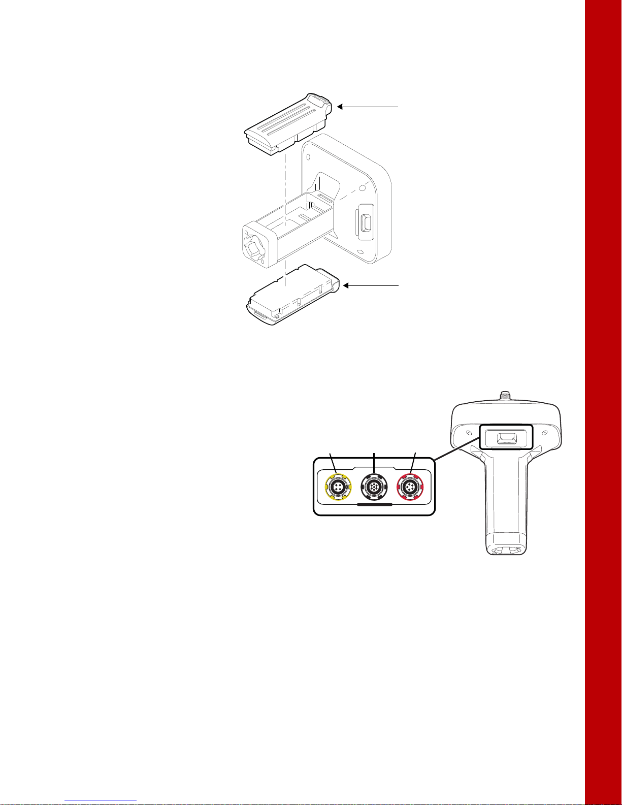
Batteries
Detachable
Battery
Detachable
Battery
USB
(yellow)
Power
(red)
Serial
(black)
The receiver comes equipped with two detachable, rechargeable batteries for powering the receiver. For more
information about using the batteries, see
Getting Acquainted
“Managing Power” on page 16.
Data and Power Ports
The Sokkia Atlas has the following three ports:
•
USB
– rimmed in yellow; used for high-speed
data transfer and communication between the
receiver and an external device. The body of
the connector on the corresponding cable is
yellow.
•
Serial Port
communication between the receiver and an
external device.
•
Power
receiver to an external power source. This port
can also be used to charge the batteries. The
body of the connector on the corresponding
cable is red.
– rimmed in black; used for
– rimmed in red; used to connect the
Figure 3: Sokkia Atlas Detachable Batteries
U
S
B
S
E
R
I
A
L
P
O
W
E
R
Batteries
P/N: 1006148-01
7
External Radio Antenna Connector
External
Antenna
Connector
The radio antenna connects to the external antenna connector on the Sokkia Atlas radome (Figure 4). The radio
antenna uses a BNC connection.
Getting Acquainted
Figure 4:Sokkia Atlas Radome and External Antenna Connector
External Radio Antenna Connector
P/N: 1006148-01
8

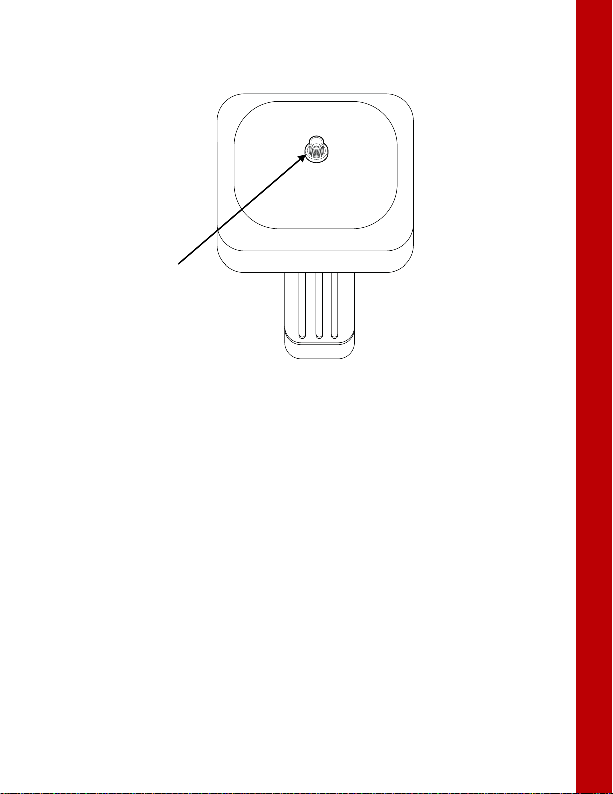
Bottom Connector
Bottom Connector
for Standard Setups
Quick Disconnect
Adapter
IMEI #
Memory
Card Slot is
SIM Card
Slot is Here
The bottom connector (Figure 5) connects the receiver to either a standard 5/8'' thread pole/adapter or the
quick disconnect. The quick disconnect adapter (p/n: 02-850905-01) connects to the range pole for the receiver
to slip into the top. Using the side clips, the receiver can be quickly connected to/disconnected from the range
pole.
Figure 5: Sokkia Atlas Quick Connector
SD/SDHC and SIM Card Slots
Getting Acquainted
The SD/SDHC and SIM card slots are located under the battery compartments near the base of the dome. F or
more information about the SD/SDHC card , see
“Memory” on page 35. For more information about SIM cards,
see “SIM Card Slot” on page 10.
Figure 6:Sokkia Atlas Card Slots
Bottom Connector
P/N: 1006148-01
9
SIM Card Slot
The SIM card slot is located to the right of the LED Display Panel inside the battery compartment. It enables
you to install a standard SIM card into the receiver. Once installed, the SIM card provides a unique identification
for the receiver’s HSPA module and enables the receiver’s HSP A f unctionalit y based on the subscribed services
(the receiver board accesses the HSPA module, which accesses the SIM card). The SIM card usuall y rem a in s
inside the receiver. You can access the HSPA module, with the SIM card installed, via SRU for configuration
purposes. A SIM card can be purchased from a local cellular provider.
The Sokkia Atlas receiver, equipped with a CDMA module, does not require a SIM card and is only
approved to work on a Verizon
or extracted from SRU, and call Verizon to activate service on the CDMA module installed on the
receiver.
The CDMA module is available on-demand in the United States only. Contact your Sokkia dealer for
more information.
SIM Cards
The SIM card must have HSPA support to communicate over a TCP/IP network.
Installing the SIM Card
1. Make sure the receiver is turned off.
2. Remove the detachable battery to the right of the LED Display panel.
3. Carefully insert the SIM card, label-side up, into the SIM card slot located at the top of the battery
compartment.
Once the receiver is turned on, the receiver board will detect the SIM card, and it will be ready to use as
needed.
®
wireless network. Note the MEID# printed on the Sokkia Atlas unit
Getting Acquainted
SD/SDHC and SIM Card Slots
P/N: 1006148-01
10
• • • • • •
Display Panel Operations
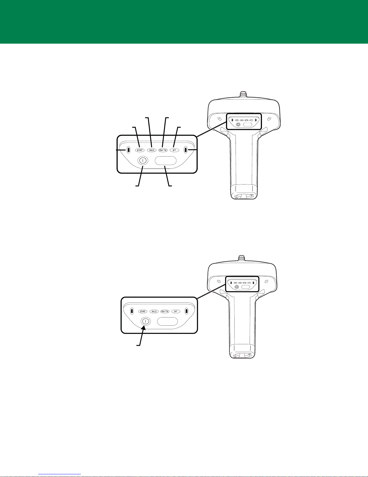
FUNCTION
FUNCTION
Battery
STAT
REC RX TX
BT
Power
Button
FUNCTION
Button
Battery
FUNCTION
FUNCTION
Power
Button
Press the power
button for about 1
second to turn the
receiver on/off.
The LED display panel (Figure 7) enables you to control receiver power and data recording. The LEDs display the
status of the satellite tracking, recording/memory capacity, Bluetooth connections, and batteries. This chapter
describes the different LED blink patterns and what they mean.
Power Button
The power button turns the receiver on and off. When turning the receiver on, press the Power button until the
LEDs briefly flash. When turning off the receiver, press the Power button until the LEDs go out.
Receiver Status LEDs
There are four status LEDs to provide you informat ion about the bat tery life, tr acked satellites, memory capacit y,
and Bluetooth wireless connectivity. This section describes the color and behavior of each LED.
Figure 7: LED Display Panel
Figure 8: Power Button Functions
Display Panel Operations
P/N: 1006148-01
11
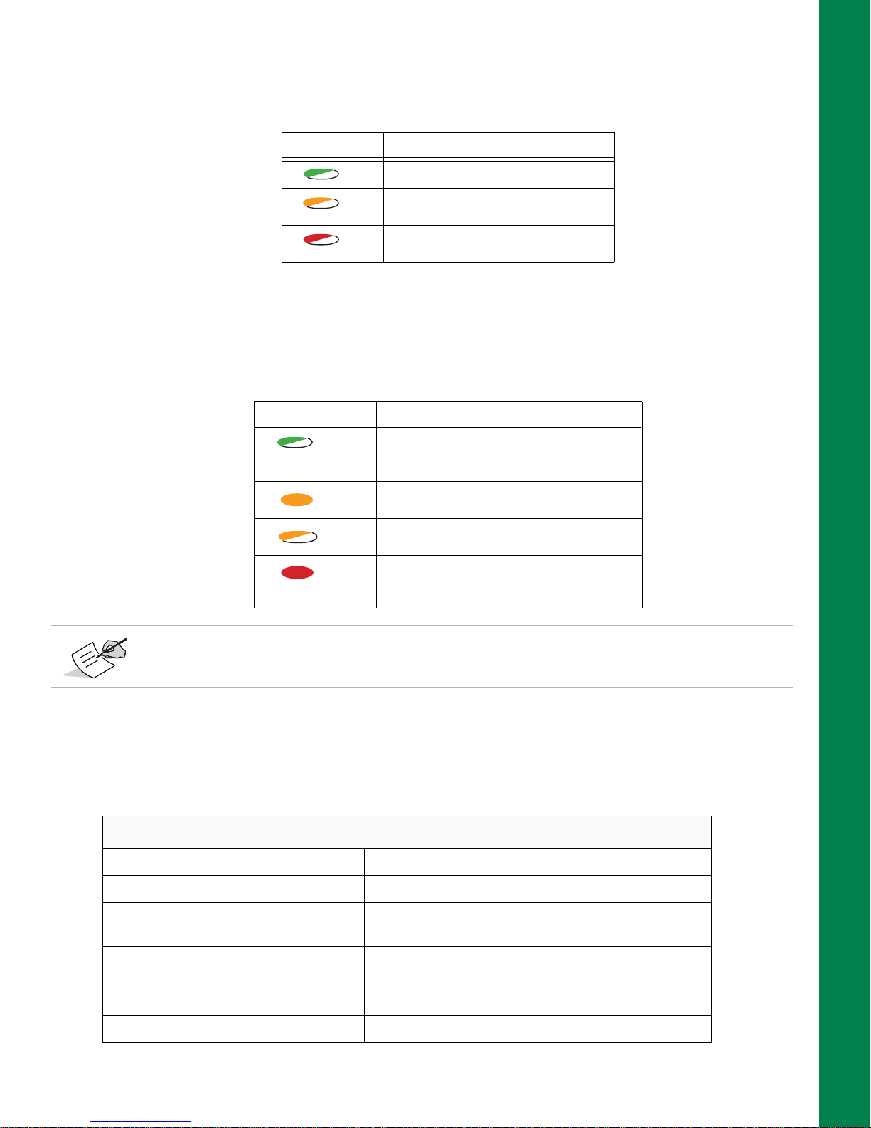
STAT LED
The tracking status LED displays the status of tracked satellites when the receiver is on.
Table 2. Status LED Patterns
LED Color Description
One blink per tracked GPS satellite.
One blink per tracked GLONASS
satellite.
One blink means no satellite is being
tracked.
REC LED
The recording LED indicates if data is being written to memory and warns if memory is available fo r recording.
For a description of the REC LED status when using the FUNCTION button, see
Table 3. Recording LED Patterns
Display Description
Green Blink: File logging is in progress. Each
blink indicates data is being written to the
SDHC card.
Solid Orange: The receiver is changing
modes.
Orange Blink: The file system is not
accessible.
Solid Red: A fault condition with the receiver
(no more memory, no SDHC card inserted, a
hardware problem, or an improper OAF.
Table 7.
Display Panel Operations
For more information on REC LED patterns, see “FUNCTION Button/Logging Data” on page 14.
RX TX LED
This LED displays the status of the modem. Table 4 describes the LED colors and patterns for the different
modems available for the Sokkia Atlas receiver.
Table 4. Sokkia Atlas LEDs
Digital UHF II
No Light Modem is turned Off
Green Flashes (green LED, off, green LED) Modem is in receiver mode
Solid Green A radio link has been established; modem is ready to
receive data
Solid Green plus yellow (green LED, green
LED + red LED)
Solid Red Modem is in transmitter mode
Red Flashes (rapid red LED, off, red LED) A fault condition has been detected
Modem is receiving data (Yellow during actual reception)
Receiver Status LEDs
P/N: 1006148-01
12

Table 4. Sokkia Atlas LEDs
Display Panel Operations
Red then Green (Red LED, off, green LED,
off)
Solid Yellow (Red LED + Green LED) Modem is initializing
Green Flashes The modem is on, registered on the network, and is
Solid Red A connection had been established
Solid Yellow (Red LED + Green LED)
Green Blinks (DUHF II or SpSp)
Yellow flashes (green LED + red LED, off) an error has occurred (initialization error, wrong PIN code
Modem is in command mode
GSM/HSPA
waiting for incoming calls
The modem is in direct control mode (Daisy Chain)
etc.)
Bluetooth LED
The Bluetooth LED displays the status of the Bluetooth activity. Table 5 describes the activity.
Table 5. Bluetooth LED Patterns
LED Color Description
Blue Blink: Bluetooth is on and waiting for a
connection.
Blue Solid: A single Bluetooth connection is
established.
Battery LED
The Battery LED indicates the remaining charge of each detachable battery. When an external power source is
utilized, the Power button LED turns solid green and begins to blink if the bat teries begin to charge. See
for more information.
No light: Bluetooth is turned off.
Table 6. Battery LED Patterns
LED Color Description
THE RECEIVER IS ON; USING BATTERY POWER
Slow Green Blink (5 sec.): The charge is greater than 85 percent.
Slow Orange Blink (5 sec.): The charge is intermediate.
Slow Red Blink (5 sec.): The charge is less than 15 percent.
EXTERNAL POWER IN USE(POWER BUTTON LED SOLID GREEN);BATTERIES ATTACHED
Fast Green Blink (1 Sec. ): The internal batteries are at greater than 85% capacity; the
batteries are being charged.
Fast Orange Blink (1 Sec.): The internal batteries are at greater than 15% capacity;
the batteries are being charged.
Fast Red Blink (1 Sec.): The internal batteries are at less than 15% capacity; the
batteries are being charged.
Table 6
a,b
a. The receiver is on or off.
b. You can also charg e the batteries using t he bat tery char ging cradle. See page “Battery Charging Cradle” on
page 17.
Battery LED
P/N: 1006148-01
13
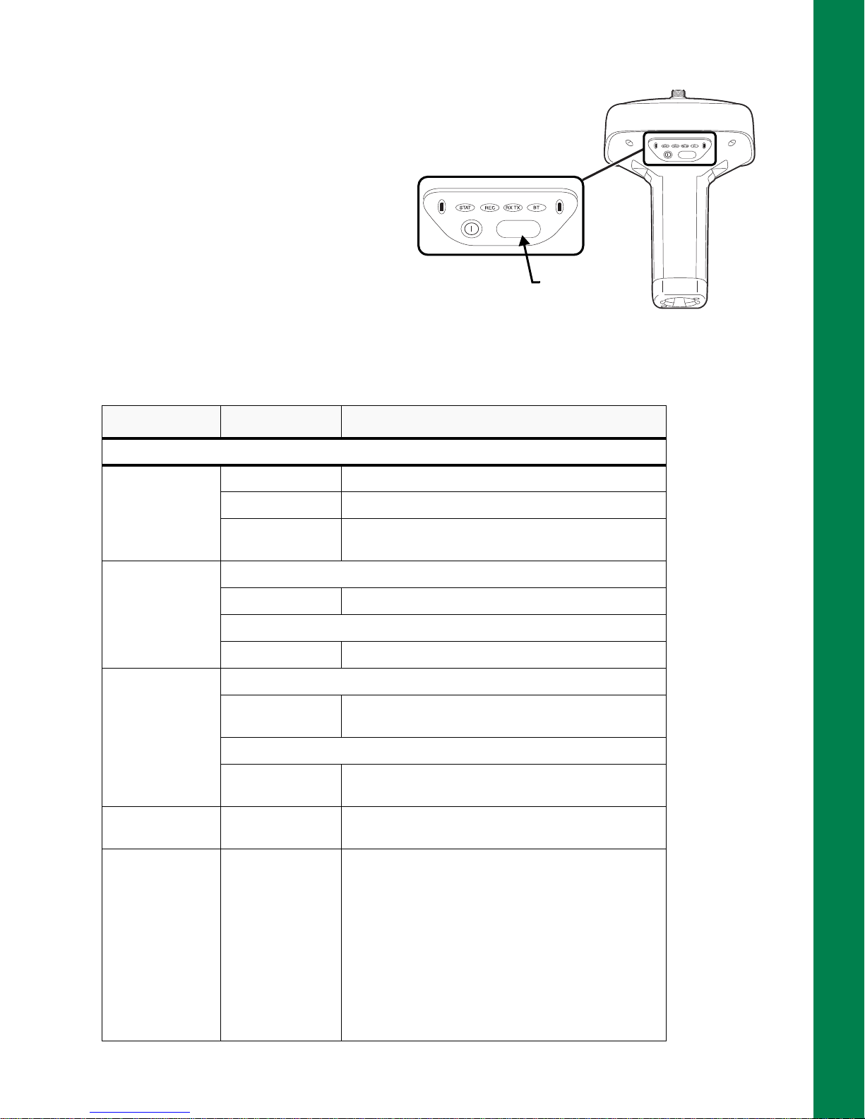
FUNCTION Button/Logging Data
FUNCTION
FUNCTION
Press the FUNCTION
button for 1–5
seconds to start/stop
data logging.
FUNCTION
Button
This button switches the receiver between
information
modes, starts/stops data recording, and
changes the baud rate of the serial port to
9600. The FUNCTION button enables you
to turn data recording on or off . Se e
to learn how to use the FUNCTION button.
Each time data recording is turned off or
on, either a new file opens or data appends
to a particular file.
FUNCTION Key REC LED Status
When data recording is off, and the FUNCTION key is...
modes and post-processing
Table 7
Table 7. FUNCTION Button Operations and REC LED Status
Display Panel Operations
Figure 9: FUNCTION Button
Not pressed
Pressed for < 1
second
Pressed for 1–5
seconds
Pressed for 5–8
seconds
Pressed for > 8
seconds
No light No data recording.
Orange blink Internal file system test in progress.
Red No free memory; hardware problem with data
recording. No SDHC card.
If FUNCTION key mode is “LED blink mode switch”
Orange Release to change information mode.
If FUNCTION key mode is “Occupation mode switch”
Orange No function.
If FUNCTION key mode is “LED blink mode switch”
Green Release to start data recording (post-processing
occupation mode undefined).
If FUNCTION key mode is “Occupation mode switch”
Green Release to start recording (Kinematic or Static post-
processing occupation mode).
Red Release to turn serial port A baud rate to 9600 bps.
No light No function.
FUNCTION Button/Logging Data
P/N: 1006148-01
14
 Loading...