

Page 1

www.soehnle
-
professional.com
Operation Manual
Terminal
3025
Page 2

2
Thank you for purchasing the Soehnle Professional Terminal 3025. This terminal was developed according to
the requirements of operational practice and offers you numerous possibilities to individually adapt the
weighing process to your needs in order to make your processes rational and cost-effective.
Please read the operating instructions carefully before use. Improper use could result in damage to you or
the terminal.
If you have any questions or have problems with your terminal that are not covered in this manual, please
contact your Soehnle Industrial Solutions service center or Soehnle Industrial Solutions Customer Service.
Telephone: +49 7191 3453-220
Fax: +49 7191 3453-211
E-Mail: info@sis.gmbh
For more information and documentation, see:
https://www.soehnle-professional.com/en/site/documents
Please go to the customer centre on our website www.soehnle-professional.com and select Terminal 3025
under Downloads / Industrial scales / Terminals.
Page 3

3
TABLE OF CONTENTS PAGE
1. GENERAL INFORMATION ........................................................................................................... 6
1.1 Purpose of use ..................................................................................................................................... 6
1.2 Safety instructions............................................................................................................................... 6
1.3 Cleaning ............................................................................................................................................... 6
1.4 Maintenance and service .................................................................................................................... 7
1.5 Warranty/Liability ................................................................................................................................ 7
1.6 Installation instructions ...................................................................................................................... 8
2. DEVICE DESCRIPTION ................................................................................................................ 9
2.1 Connection and device description .................................................................................................... 9
2.2 Technical data ..................................................................................................................................... 9
2.3 Symbols in the display ...................................................................................................................... 10
2.4 Calibration notes ............................................................................................................................... 11
2.4.1 Nameplate.................................................................................................................................. 11
2.4.2 Calibration counter .................................................................................................................... 11
2.5 Switching on / off .............................................................................................................................. 12
3. OPERATING CONCEPT ............................................................................................................. 13
3.1 Setting mode ...................................................................................................................................... 13
3.2 Program mode ................................................................................................................................... 14
3.3 Function keys ..................................................................................................................................... 14
3.4 Input and control keys ....................................................................................................................... 14
4. SETTING MODE ......................................................................................................................... 16
4.1 Calling up the setting mode .............................................................................................................. 17
4.2 Program settings ............................................................................................................................... 18
4.3 Setting mode – Terminal settings .................................................................................................... 19
4.4 Setting mode – Scale settings.......................................................................................................... 25
4.5 Setting mode – Communication settings ........................................................................................ 28
4.6 Setting mode – Service settings ...................................................................................................... 37
4.7 Reset terminal .................................................................................................................................... 37
5. BASIC FUNCTIONS ................................................................................................................... 38
5.1 Switch on............................................................................................................................................ 38
5.2 Switch off ........................................................................................................................................... 38
5.3 Program selection ............................................................................................................................. 38
5.4 Set to zero .......................................................................................................................................... 38
5.5 Tare function ...................................................................................................................................... 39
5.6 Gross display ..................................................................................................................................... 39
5.7 Scale switching .................................................................................................................................. 39
5.8 Tenfold display x10 ........................................................................................................................... 40
5.9 Hold function ..................................................................................................................................... 41
5.10 Auxiliary display ............................................................................................................................... 42
5.10.1 Second unit .............................................................................................................................. 44
5.11 Organisation data (Identifier) ......................................................................................................... 46
5.12 Alphanumeric input ......................................................................................................................... 49
5.13 Key lock ............................................................................................................................................ 50
5.14 User password ................................................................................................................................. 51
5.15 Login function / Process start function ......................................................................................... 51
5.16 SD - card data backup ..................................................................................................................... 56
6 APPLICATION PROGRAMS ....................................................................................................... 57
6.1 Selection of application programs ................................................................................................... 57
6.2 Function keys ..................................................................................................................................... 57
Page 4

4
6.3 Navigation in the application programs ........................................................................................... 58
6.4 Special programs............................................................................................................................... 58
6.5 Weighing and Taring ......................................................................................................................... 59
6.5.1 Function keys ............................................................................................................................. 59
6.5.2 Display view ............................................................................................................................... 59
6.5.3 Display information field ........................................................................................................... 60
6.5.4 Weighing without taring ............................................................................................................ 61
6.5.5 Manual taring ............................................................................................................................. 61
6.5.6 Taring with manual tare input ................................................................................................... 61
6.5.7 Multiplicative tare ...................................................................................................................... 62
6.5.8 Additive tare ............................................................................................................................... 62
6.5.9 Provisional tare .......................................................................................................................... 63
6.5.10 Automatic taring ...................................................................................................................... 63
6.5.11 Fixed tare memory .................................................................................................................. 64
6.5.12 Error messages during taring ................................................................................................. 65
6.5.13 Display options with the Info key ............................................................................................ 65
6.5.14 Transfer of current values to the fixed memory .................................................................... 66
6.5.15 Organizational data (Identifier)............................................................................................... 66
6.5.16 Settings in the Setting Mode .................................................................................................. 67
6.6 Totalising and picking ....................................................................................................................... 69
6.6.1 Function keys ............................................................................................................................. 69
6.6.2 Display view ............................................................................................................................... 70
6.6.3 Display information field ........................................................................................................... 71
6.6.4 Tare function .............................................................................................................................. 71
6.6.5 Operating the totalising function .............................................................................................. 72
6.6.6 Selection options for the totals display.................................................................................... 73
6.6.7 Relief factor for totalising ......................................................................................................... 73
6.6.8 Auto total / pick ......................................................................................................................... 73
6.6.9 Reference scale for totalisation................................................................................................ 73
6.6.10 Assigning and deleting the sequential number ..................................................................... 74
6.6.11 Item counter ............................................................................................................................ 74
6.6.12 Print-triggering keys ................................................................................................................ 74
6.6.13 Display of current totals .......................................................................................................... 74
6.6.14 Display individual items .......................................................................................................... 75
6.6.15 Display options with the Info key ............................................................................................ 76
6.6.16 Transfer of current values to the fixed memory .................................................................... 76
6.6.17 Organizational data (Identifier)............................................................................................... 77
6.6.18 Settings in the setting mode ................................................................................................... 77
6.7 Counting ............................................................................................................................................. 79
6.7.1 Function keys ............................................................................................................................. 79
6.7.2 Display view Counting ............................................................................................................... 80
6.7.3 Display information field ........................................................................................................... 81
6.7.4 Tare function .............................................................................................................................. 81
6.7.5 Counting function ...................................................................................................................... 82
6.7.6 Totalising and Picking ............................................................................................................... 84
6.7.7 Reference statistics ................................................................................................................... 88
6.7.8 Piece control .............................................................................................................................. 89
6.7.9 Counting with several weighing bridges .................................................................................. 90
6.7.10 Counting accuracy................................................................................................................... 91
6.7.11 Display options with the Info key ............................................................................................ 93
6.7.12 Transfer of current values to the fixed memory .................................................................... 93
6.7.13 Organizational data (Identifier)............................................................................................... 94
6.7.14 Settings in the setting mode ................................................................................................... 95
Page 5

5
6.8 Checking ............................................................................................................................................ 99
6.8.1 Function keys ............................................................................................................................. 99
6.8.2 Display view ............................................................................................................................. 100
6.8.3 Display information field ......................................................................................................... 101
6.8.4 Tare function ............................................................................................................................ 101
6.8.5 Control function ....................................................................................................................... 101
6.8.6 Totalising and Picking ............................................................................................................. 104
6.8.7 Display options with the Info key ............................................................................................ 108
6.8.8 Transfer of current values to the fixed memory .................................................................... 108
6.8.9 Organizational data (Identifier) ............................................................................................... 109
6.8.10 Settings in the setting mode ................................................................................................. 109
7. ERROR MESSAGES ................................................................................................................. 113
8. ADDITIONAL INFORMATION .................................................................................................. 113
Page 6

6
1. GENERAL INFORMATION
1.1 Purpose of use
The Soehnle Professional Terminal 3025 is a calibratable terminal for use in scales and weighing systems
with standard DMS weighing and load sensors. Up to two analogue measuring points (scales) can be
connected internally at the same time. Another scale can be connected via the serial interface, e.g. as a
reference scale. Additional data can be entered via the keyboard. Various interface options are available for
connecting printers, EDP systems, readers, data storage devices and an external PC keyboard.
The Soehnle Professional Terminal 3025 is designed to work effectively in harsh environments. It is robust,
easy to clean, flexible and fast. Its logical structure and user guidance allow quick familiarisation and
intuitive work at the terminal. Its design adapts to your individual requirements and supports you in your task.
1.2 Safety instructions
Before operating the terminal, please read the information listed in the operating instructions carefully. They
contain important information for the installation, intended use and maintenance of the terminal.
The manufacturer is not liable if the following instructions are not observed:
If electrical components are used under increased safety requirements, the relevant regulations must be
observed. Never service the terminal while it is live. The warranty does not apply in the event of improper
installation.
> The Terminal 3025 must not be used in hazardous or explosion-endangered areas.
> The permissible mains voltage is 100 - 240 volts.
The socket must be earthed and easily accessible.
> The terminal may only be opened by trained Soehnle Industrial Solutions service technicians.
There are no user serviceable parts in the housing. In case of external intervention your warranty
claim expires.
> Repairs and the replacement or installation of parts may only be carried out by a trained
Soehnle Industrial Solutions Service Center.
> If the power cord is damaged, the terminal must not be operated. Interrupt the power supply and
call a Soehnle Industrial Solutions service center.
> If the terminal is used in custody transfer applications, the do not damage the attached safety
markers.
Contact your Soehnle Industrial Solutions service partner if you have any problems.
1.3 Cleaning
A damp cloth and commercially available cleaning agents are sufficient for cleaning.
Do not use abrasive or corrosive agents.
Page 7

7
1.4 Maintenance and service
Note:
These devices comply with the applicable EC Directives 2014/31/EU, 2014/30/EU, 2014/35/EU and
EN45501. However, under extreme electrostatic and electromagnetic influences, e.g. when operating a radio
or mobile phone in the immediate vicinity of the equipment, the scale may be affected.
At the end of the disturbance influence, the product can again be used as intended,
If necessary, a restart is necessary. In case of permanent electrostatic interference, we recommend
grounding the terminal housing and the platform.
The terminal is a measuring instrument. Drafts, vibrations, rapid temperature changes and solar radiation can
affect the weighing result. The terminal complies with protection class IP 67. Very high humidity, vapours,
aggressive liquids and heavy soiling must be avoided.
1.5 Warranty/Liability
Insofar as Soehnle Industrial Solutions is responsible for a defect in the delivered item, Soehnle Industrial
Solutions shall be entitled either to remedy the defect or to deliver a replacement. Replaced parts shall
become the property of Soehnle Industrial Solutions.
If the rectification of the defect or replacement delivery fails, the statutory provisions shall apply.
The warranty period begins on the day of purchase. Please keep the invoice as proof. If service is required,
please contact your dealer or Soehnle Industrial Solutions customer service.
In particular, no warranty is given for damage caused for the following reasons arise:
Unsuitable, improper storage or use, faulty assembly or commissioning by the customer or by third parties,
natural wear and tear, changes or interventions, faulty or negligent treatment, in particular excessive strain,
chemical, electrochemical, electrical influences or moisture, provided that these are not due to a Soehnle
Industrial Solutions' debt.
If operational, climatic or other influences should lead to a significant change in the conditions or the
condition of the material, the warranty for the faultless overall functioning of the equipment is void. Insofar
as Soehnle Industrial Solutions provides a guarantee in individual cases, this means that the delivery item is
free from defects during the guarantee period. Please keep the original packaging for any return transport.
Page 8

8
1.6 Installation instructions
Please check packing and terminal for external damage. Do not operate a visibly damaged terminal, but
inform your dealer. Please keep the packaging for possible shipment.
The terminal is designed for rough commercial use. However, it is a sensitive instrument whose performance
can be affected by unfavourable environmental factors.
After unpacking or transport, acclimatize for 2 hours at room temperature.
The permissible ambient temperature is -10° to +40° C.
The place of installation is a decisive factor for the functioning of your scale.
Protect the terminal as far as possible from shocks, vibration, strong heat or cold, temperature fluctuations,
draughts, chemicals and moisture by selecting the appropriate installation location.
Page 9

9
2. DEVICE DESCRIPTION
2.1 Connection and device description
2.2 Technical data
Passage
membrane
I/O interface
Interface 1
Interface 2
Interface 3
Interface 4
Measuring point 1
Measuring point 2
Ethernet
Grounding Power supply
> Stainless steel housing, protection class IP 67, integrated power supply 100 - 240 V AC, 50/60 Hz
> Membrane keypad with a total of 32 keys, 6 function keys, 4 organisation data keys, alphanumeric
input via numeric keypad
> Connection option for external PC keyboard
> Colour display TFT 3.5" QVGA, dot matrix 320 x 240 pixels dimmable backlit
> Option: Soehnle Professional Micro-SD card (high-quality SLC memory card), memory capacity: fixed
memory for a total of 999 fixed values across programs, alibi memory for 4 million entries and for
software updates
> Interfaces: 1 x RS 232 or USB in the basic version.
> Internal with R232, USB and Ethernet, 2 additional interface slots (RS232).
> Option: IO card for 6 outputs and 4 inputs freely assignable
> Working temperature: -10° C to +40° C
> 1 analogue measuring point in the basic version, 1 additional analogue measuring point can be
connected
internally. Calibratable resolution 10,000,000 e, internal resolution 16,000,000 d
> Verifiable according to accuracy class III and IIII for n = 10 000 e with multi-range and multi-interval
scales
> Smallest permissible input signal per calibration value = 0.2 µV, Load cell impedance 40 Ohm
to 1,245 Ohm
> Connection of a digital reference scale via RS232 interface
Page 10
10
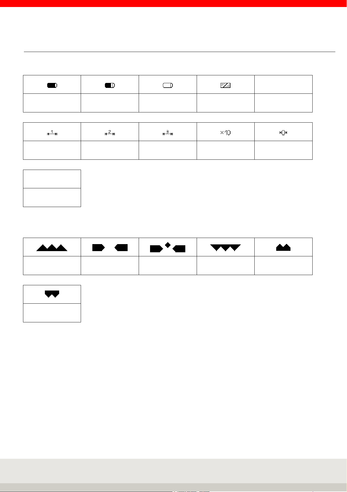
2.3 Symbols in the display
Symbols in the display toolbar
Alibi memory
fill level 100%
Alibi memory
fill level 80%
Alibi memory fill
level empty
Key lock Data logger
Multi range 1 Multi range 2 Multi range 3 Resolution X10 Zero
HLD
Hold function active
Symbols in the information field of the display
LOG
Below tolerance Within tolerance
Setpoint reached
exactly
Above tolerance Under minimum load
Above upper limit
class 5
Symbol for standstill
After the sample has been placed on the scale, it needs time to settle.
As long as no stability has been reached, the dimension symbol (kg, g) is hidden.
If stability has been reached and a stable value is available, this is indicated by the dimension sign fading in.
Page 11
11
2.4 Calibration notes
The scope of this information is Germany. In other countries, conformity with national laws must be checked.
Terminal 3025 is approved within the EU for Class III and IIII custody transfer.
It corresponds to the type described in the type approval as well as to the applicable requirements of
Directives 2014/31/EU, 2014/30/EU, 2014/35/EU and EN 45501.
In accordance with legal requirements, calibrated scales must be recalibrated at regular intervals. Please
contact a Soehnle Industrial Solutions service center or your local calibration office.
Do not under any circumstances damage the official seals, otherwise the calibration validity will expire.
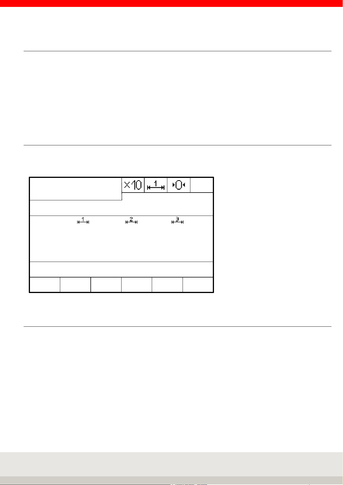
2.4.1 Nameplate
The terminal has an electronic nameplate.
Display after pressing the Info button:
Gross
Brutto/
/Net
Netto
Weight value
Gewichtswert
Max
Min
e=
SNR XXXX/XX-XXXX Eichz: XXXX IDENT-Chip
F 1 F 2 F 3 F 4 F 5 F 6
Dimension
Dimensions-
symbol
zeichen
01
2.4.2 Calibration counter
The calibration counter indicates how often a scale has been calibrated. The stored counter reading must
match the calibration counter reading secured by a sticker. The current calibration counter reading can be
displayed in the setting mode under Scale / Scale parameters for each connected scale.
Page 12

12
2.5 Switching on / off
Switch on:
Press the ON/OFF button .
When switching on, the logo, terminal type 3025, filter type and the detected measuring points are briefly
displayed during the start routine.
The scale is set to zero after power-up.
When the scale is switched on, the last application program used is reactivated.
Switch-on zero setting limits:
Approvable: Switch-on zero range 20 % of the weighing range.
The default value is -5% to +15% of the weighing range. Optional: extended range on request.
Non-approvable: the switch-on zero range can be from -99% to +99% of the weighing range.
If the scale is switched on outside the power-on zero range, an error message is displayed.
If the terminal is not approvable, it then goes directly into weighing mode, while if it is approvable, you can
use the zero key to jump to weighing mode. The current weight value is then displayed with the previously
stored zero point. If you remove the cause of the underload or overload, the scale will go to zero and is ready
for operation without having to be switched on again.
Backlight and colour
Can be adjusted in: Setting mode / Terminal / Display.
The default setting is 80% for the backlight and white for the background colour.
Behaviour in case of power failure
The scale returns to the state it was in when the power was restored.
Switch off
Press the ON/OFF button .
If the connected measuring point is loaded, or if you have called up a menu, the scale does not switch off
until you press the ON/OFF key for 3 seconds.
It is not possible to switch off the scale while it is waiting for an entry in the editing area of the setting mode.
To switch off the scale, you must leave the editing area.
OFF-display
In the setting mode Service (incl. password prompt) /General/OFF display, you can set whether the word
"OFF" appears in the display when the terminal / scale turned off Default setting is "with OFF display".
Page 13

13
3. OPERATING CONCEPT
The operating concept is divided into two functional areas:
• Setting mode
• Program mode
3.1 Setting mode
Here you can make individual settings on the terminal to optimize the scale for your requirements.
Table setting mode:
Program settings
Weighing + taring
Totalising and picking Display
Counting
Checking
I/O port programming Organizational data USB
Terminal
Version
Keypad
Date/Time
Error memory
User password
Log in function
Reset terminal
Setting mode
Scale Communication
Scale parameter Alibi memory
Allocation table
measuring points
Reference points
for calibration
Internal measuring
point
Ethernet
Print template
Data processing settings
Barcode
Interface 1 RS232 (internal) service-
Interface Port 2
Interface Port 3
Service
for
Specialists
only
SD card
data backup
Batch processing
IO control
Page 14
14
3.2 Program mode
Select the desired weighing application program here. Once you have selected the application program and
called it up, the scale is ready to weigh.
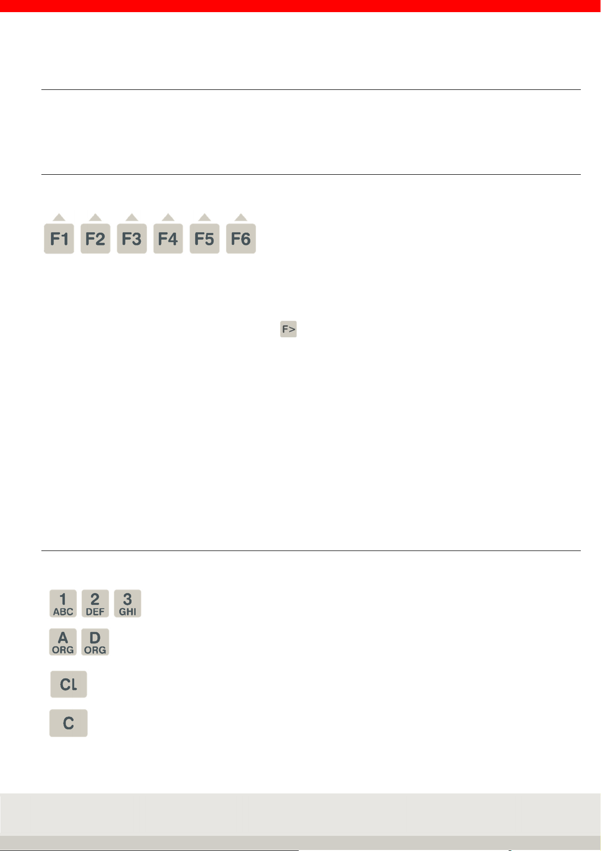
3.3 Function keys
The function keys F1 to F6 are available for calling the functions.
These assume different functions depending on the program and situation. The respective function is shown
in the display in the function bar above the key.
Depending on the program, the function keys are assigned in up to 4 levels, the change through the levels
takes place rolling with the function change key .
Navigation with the function keys
↑ Move the marker up in the list.
↓ Move the marker down in the list.
End Exiting the setting mode
Continue Call of the marked menu item
Back Return to superordinate level
Cancel Return without accepting a change
Delete Deleting an item with a return jump
Accept Acceptance of an entry or change
→ Cursor to the right
← Cursor to the left
3.4 Input and control keys
The following additional keys are available for input and control:
Numeric keys for entering numerical values,
Multiple assignment of the number keys for entering letters
Call organizational data
Delete the complete input or reset the functions
Delete the last digit
Page 15
15
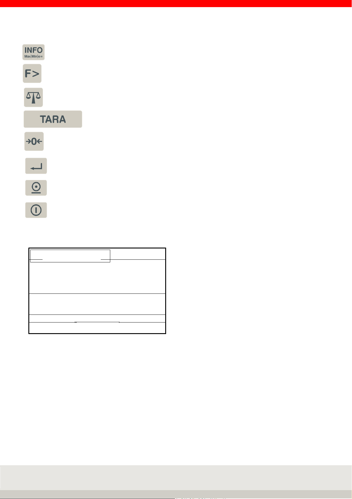
Auxiliary
display
Symbol bar
Display field
Range display
Info key, electronic nameplate with approval data,
Calling information about the application programs
Function change key
Scale change key
Tare key
Zero setting key / delete tare
Enter key
Print key
On / Off
Display:
The display shows different views depending on the situation.
It is divided into the following display fields:
NEBENANZEIGE
INFORMATIONSFELD
Information field
ANZEIGEFELD
BEREICHSANZEIGE
FUNKTIONSLEISTE
SYMBOLLEISTE
Auxiliary display:
Displays additional information and can be set individually under Terminal / Display.
Can be switched on and off by pressing the F3 key.
Symbol bar:
Shows information on the status of the connected measurement loop.
Information field:
Shows organizational data, totals during totalising, special control characters, classes during classification,
operator guidance, switching points depending on situation or individually adjustable.
Display field:
Displays weight value, number of pieces, dimension indicator
Range display:
Displays the current weighing range with Max / Min / e (d).
Function bar:
Functions of the 6 situation-dependent assigned function keys
Page 16

16
4. SETTING MODE
The setting mode stores program and weighing parameters that can be called up and individually configured.
Adjustment can be made by entering data or selecting from predefined parameters.
The individual parameters are stored in logical groups within a multi-level family tree structure.
Note:
Setting Mode structure:
The modification options may be limited in the legal metrology sector.
Program settings
Weighing + taring
Totalising and picking Display
Counting
Checking
I/O port programming Organisation data
Terminal
Version
Keypad
Date/Time
Error memory
User password
Log in function
Reset terminal
Setting mode
Scale Communication
Scale parameter Alibi memory
Assignment table for
measuring points
Reference points
for calibration
internal measuring
point
USB
Ethernet
Print template
Data processing settings
Barcode
Interface 1 RS232 (internal) service-
Interface Port 2
Interface Port 3
Service
for
Specialists
only
SD card
data backup
Batch processing
IO control
Page 17

17
4.1 Calling up the setting mode
Switch on the terminal.
After the power-on routine, the terminal will automatically start the application program that was last
activated. To call up the setting mode, use the function change key to switch to the setting functions
level.
Function keys:
Level Setting functions
Gross x 10
F 1 F 2 F 3 F 4 F 5 F 6
Auxiliary
display
Program
Press the F6 Setting Mode key.
You are now in the selection menu Setting mode.
Navigation in Setting Mode:
The function keys F1 to F6 are available for controlling the functions.
They assume different functions depending on the program and situation.
The respective function is shown on the display in the function bar.
Meaning of the function keys:
↑ Move the marker up in the list.
↓ Move the marker down in the list.
End Exiting the setting mode
Continue Call of the marked menu item
Back Return to superordinate level
Cancel Return without accepting a change
Delete Deleting an item with a return jump
Accept Acceptance of an entry or change
→ Cursor to the right
← Cursor to the left
Setting
Mode
Page 18

18
Entries in the setting mode:
In most cases, you make a selection from the various settings offered.
For editable values, numeric or alphanumeric input is possible via the keyboard.
Service area:
The Service area is protected by a password.
The contained parameters can only be maintained by trained service personnel.
Please contact your Soehnle Industrial Solutions service center.
4.2 Program settings
In the Program Settings setting mode, you can adapt the user programs of your scale to your specific
requirements. How to activate the application programs and their typical applications are described in Part 6
Application Programs.
1 Weighing + taring
Settings and parameters see chapter 6.5.16
2 Totalising and picking
Settings and parameters see chapter 6.6.18
3 Counting
Settings and parameters see chapter 6.7.14
4 Checking
Settings and parameters see chapter 6.8.10
5 I/O port programming (Dynamic switching)
Settings and parameters see manual chapter 6.9.11
Page 19

19
4.3 Setting mode – Terminal settings
In the setting mode under Terminal you will find the following query and setting options
1 Version
Bootloader Software Query software status
LRS Software Query software status
User software Query software status and filter type
Serial number central board Query the factory-set serial number
Character set Character set (in later version as selection):
- Latin 1
Print parameter Output of all setting parameters of the terminal incl. the currently connected
measuring point via the interface with the use "EDP 2 (unidirectional)".
2 Display
Backlight Input
Setting luminosity, input in percent via numeric keypad
30% is darker, 100% is full luminosity
Factory setting: 80%.
Background colour Selection
Background colour setting
> green
> white
> light blue
> yellow
> blue
> magenta
> red
Factory setting: white
Language Selection
1. language German (factory setting)
2. language English or other languages
can be customized via the Soehnle Professional service program.
Page 20

20
2 Display
Auxiliary display Selection
> Second unit
> Tare value
> x10 Resolution
> Gross/net
> Current weight
> Reference quantity
> Reference weight
> Setpoint
> Difference to setpoint
> Signal light
Factory setting: Second unit
Decimal separator Selection
Comma, dot or none.
Factory setting: Decimal point
Thousands separator Selection
for separators only for counted quantity display
Comma, dot or none.
Factory setting: None
3 Keypad
Keypad key Single, multiple or all keys can be locked on the keyboard.
By pressing the key to be locked, the status of the key can be changed from open
to locked and vice versa.
Press the Enter key to save and exit for 3 seconds.
Key tone Selection off or on
Keyboard confirmation beep
Factory setting: off
Validation tone Selection off or on
Receipt beep (e.g. error message or transfer)
Factory setting: off
Keyboard layout Selection German or French
Layout for PC keyboard assignment and keyboard looping via the USB interface
connection
Factory setting: German
Page 21

21
4 Date / time
Time Input via numeric keypad, clock starts to run Press the Enter key
Date Input via numeric keypad
Date format Selection European or imperial date
Factory setting: European
Use-by period (Days)
Input via numeric keypad in days [d]
Factory setting: 0 d
5 Organisation data
Description ORG A Input
Name of the organizational data memory A
Numbers or plain text via keyboard, e.g. "Article no." max. 12 characters
Description ORG B Input
Name of the organizational data memory B
digits or plain text via keyboard, max. 12 characters
Description ORG C Input
Name of the organizational data memory C
digits or plain text via keyboard, max. 12 characters
Description ORG D Input
Name of the organizational data memory D
digits or plain text via keyboard, max. 12 characters
Page 22

22
5 Organisation data
ORG data A fixed values Selection of existing fixed values from the database
Scroll with the arrow keys F3 and F4.
Call the desired fixed value with F6 Edit.
Editing an existing fixed value from the database
Press F6 to call up editing of the selected fixed value.
Parameter number is marked, call via F6 Edit, input via numeric/alpha keyboard.
Accept the entry with F6.
(Cancel without accepting the entry with F5 Back)
Parameter Entry is highlighted, call via F6 Edit, input via numbers/alpha keyboard.
Accept the entry with F6.
(Cancel without accepting the entry with F5 Back)
Delete an existing fixed value
Scroll with the arrow keys F3 and F4.
Delete the marked fixed value with F2 Delete.
The resulting gap in the consecutive numbering is closed.
Create new fixed value
Press F1 New.
The memory location number is assigned by the terminal. The first number in
brackets indicates the free memory locations, the second number the occupied
memory locations.
Parameter number is marked, call via F6 Edit, input via number/alpha keyboard.
Accept the entry with F6.
(Cancel without accepting the input with F5 Cancel)
Parameter entry is marked, call via F6 Edit, entry of entry 1 to 6 via numbers/alpha
keyboard. Accept the entry with F6.
(Cancel without accepting the entry with F5 Cancel)
Exiting the database
Press F5 back to exit the list.
Note: the optional Micro SD card (Alibi memory) is required to use the fixed values.
ORG data B fixed values As ORG data A fixed values
ORG data C fixed values As ORG data A fixed values
ORG data D fixed values As ORG data A fixed values
Call fixed values Selection of whether the fixed value is called up via consecutive memory location
number or article number.
Factory setting: Article number
Page 23

23
6 Error memory
Error list Request the error list with position, date, time of last error, number of errors, error
number and description. Scroll back using the arrow keys or F5.
Protocol memory Query the list of the download protocol memory with position, date, time, code no.
and description. Scroll back using the arrow keys or F5.
7 User password
New / Edit Input alphanumeric
Password with up to 8 characters via keyboard
After activation, access to the setting mode and the program selection is only
possible by entering the correct password.
If the password is forgotten, the entry CLEAR gives one-time access.
Clear Deletes the password and gives access again
8 Login function
Activation Selection on or off
Factory setting: off
Password request Selection on or off
Factory setting: off
Create/change password Input of the internal terminal password
System alphanumeric via the numeric keypad.
Password with up to 35 characters.
After activation, access is via a password query, e.g. after switching on the
terminal or after logging off by pressing the
C button for 3 seconds.
Delete password Press the F6 Continue key to delete the password.
Enter login text Enter the login query text
Alphanumerically via the numeric keypad.
Text length up to 35 characters.
9 Reset terminal
Reset terminal Selection execute or do not execute
Execute deletes all individual settings of the terminal and resets to factory
settings. Scale parameters, read-only memory and the print image are not reset.
Page 24

24
10 SD card data backup
Import By accepting F6 Next the current user settings are loaded from the micro SD card.
The security prompt Import comes with YES or NO. If NO is selected, no data is
loaded.
Export The current user settings are saved on the micro SD card by accepting F6
Continue.
Export for autom. import The current user settings are saved on the micro SD card and the setting
parameters are automatically reloaded in the event of a software problem.
Page 25

25
4.4 Setting mode – Scale settings
In the first step, select the scale (measuring point) with the scale change key,
for which you want to make settings.
Only connected and active scales (measuring points) are displayed for selection.
The settings and queries are made individually for each scale (measuring point).
All setting and query options are identical for all scales (measuring points).
In the setting mode under Scale, you will find the following query and setting options
1 Scale parameters
Calibration counter Query
of the current value of the calibration counter
Calibratable Query off or on
Note: Approvable can mean limited selection if parameter settings contain options
relevant to approval.
Selection only possible in the service area, subject to approval.
Filter settings Selection
> Service setting (direct modification of filters possible in the service area)
> Livestock scale
> Calm
> Normal
> Troubled
Factory setting: Service setting
The selection function is only possible with the release user filter setting in the
service area.
Hold mode Selection
> not active: no hold function
> Still/key: Hold at stability outside zeroing range,
Cancel by pressing the power button
> Still/empty: Hold at standstill outside zeroing range,
Cancel by relieving the load on the scale
> Max/key: Hold at maximum value reached,
Cancel by pressing the power button
> Max/empty: Hold at maximum value reached,
Cancel by relieving the load on the scale
> Drag/key: Hold when weight is increased and stability is reached,
Cancel by pressing the power button
> Drag/empty: Hold when weight is increased and stability is reached,
Cancel by relieving the load on the scale
Factory setting: not active
Zero tracking Query off or on
off: no zero tracking
on: Correction of drift on scale to zero
Zero tracking verifiable: 0.5 d/s
Zero tracking not verifiable: 2 d/s
Selection only possible in the service area, subject to calibration
Page 26

26
1 Scale parameters
Zero range at power-on Query off or on
When the scale is turned on, it sets the zero range of the weighing range to zero
when the power is turned on.
Selection only possible in the service area, subject to calibration.
Auto tare Selection off or on
off: No auto tare
on: Automatically tares the first weight value above the empty signal after stability
on the scale.
Factory setting: off
Additive tare Selection off or on
off: New tare overwrites old tare
one: New taring adds new tare to the existing tare.
Please note: The function Tare totalising on has an influence on tare sequences
and totals. The description in the manual always refers to the Total tare setting.
Factory setting: off
Second unit Selection
> g
> t
> lb
> mg
> oz.
Can be activated as auxiliary display function in the display via key F3 Auxiliary
display in weighing mode.
In the selection, the adjusted unit is not displayed as the first unit.
Empty message Input
of the percentage of the weighing range in which the empty message is displayed.
Enter the percentage using the numeric keypad.
(Info: Empty message is not shown on the display.)
Factory setting: 0.10 %.
Check mode Query or input off or on
on switches on a 10-fold higher resolution in the display constantly and
deactivates the x10 key.
Only possible with non-verifiable scales.
Serial number MP Query of serial number Measuring point (MP)
Software version MP Query of the software status of the measuring point (MP)
Page 27
27
For the measuring point numbers hardware addressing (system) variable new user - measuring point
numbers (user) can be assigned.
Select the desired system address Sys: xx with the arrow keys, then with F6 Next enter the desired new user
address Use: xx, then accept with F6.
With the user address Use: 00, the system address is automatically used.
Multiple assignment of the same measuring point numbers is possible.
2 Allocation table for measuring points
Sys: 01 Use: 10
Sys: 02 Use: 00
Sys: 00 Use: 00
Sys: 00 Use: 00
Sys: 00 Use: 00
Sys: 00 Use: 00
System No. 01 User No. 10 (new measuring point no. = 10)
System No. 02 User No. 00 (measuring point no. = 02)
System No. 00 User No. 00
System No. 00 User No. 00
System No. 00 User No. 00
System No. 00 User No. 00
Querying the calibration points helps service personnel to check the scale.
3 Reference points for calibration
Zero point raw measured
value
Current raw measured value Query of the current raw measured value (variable depending on the load on the
Reference point 1
weight value
Reference point 1
raw measured value
Query of the adjusted raw measured value from the zero point
scale)
Query of the weight value from the 1st support point
Query of the adjusted raw measured value from the 1st support point
Reference point 2
weight value
Reference point 2
raw measured value
Reference point 3
weight value
Reference point 3
raw measured value
Reference point 4
weight value
Reference point 4
raw measured value
Query of the weight value of the 2nd support point
Query of the adjusted raw measured value from the 2nd support point
Query of the weight value of the 3rd support point
Query of the adjusted raw measured value from the 3rd support point
Query of the weight value of the 4th support point
Query of the adjusted raw measured value from the 4th support point
The internal measuring point is located on the central board of terminal 3025 with measuring point number 01.
Page 28

28
4 Internal measuring point
Operating mode Query or selection off or on
With off the internal measuring point is deactivated with on measuring point 01 is
active.
Factory setting: on
4.5 Setting mode – Communication settings
In the setting mode under Communication you will find the following query and setting options
1 Alibi memory
Memory capacity Query
Memory size 4.000.000 = 100%
(Display only with integrated and activated alibi memory)
Memory used Query
of the currently occupied filling level incl. percentage display (e.g. 162 = 0%)
Find (single input) Search
Single entry via input consecutive number
Find function Search
Multiple entries by entering oldest and youngest consecutive number
Search (additional field) Search
Single entry via input contents additional field
Assignment of additional
data
Selection
> None
> Barcode
> Org data A
> Org data B
> Org data C
> Org data D
> Date/Time
> Price labelling (special software)
2
Usage of serial interface Selection
Interface 1 RS232 (internal)
(Further details see also interface description 470.508.090)
> none
> 2795.14
> 2795.12+2795.20
> Data processing
> EDP 2 (unidirectional)
> Barcode
> Second / large display
> Digital scale
If the device is already used via another interface output, this selection position is
displayed with disabled.
Factory setting: 2795.14
Page 29

29
2
Baud rate Selection
Data bits Selection
Parity Selection
Xon/Xoff Selection
Interface 1 RS232 (internal)
(Further details see also interface description 470.508.090)
> 1200
> 2400
> 4800
> 9600
> 19200
> 38400
Factory setting: 9600
> 7
> 8
Factory setting: 8
> none
> even
> odd
Factory setting: none
off or on
Factory setting: off
Factory settings Selection
Do not execute: Individual settings on the interface are retained
Execute: Resets interface to factory setting
3
Usage of serial interface Selection
Baud rate Selection
Interface Port 2
(Further details see also interface description 470.508.090)
> none
> 2795.14
> 2795.12+2795.20
> Data processing
> EDP 2 (unidirectional)
> Barcode
> Second / large display
> Digital scale
If the device is already used via another interface output, this selection position is
displayed with disabled.
Factory setting: none
> 1200
> 2400
> 4800
> 9600
> 19200
> 38400
Factory setting: 9600
Page 30
30
3
Data bits Selection
Parity Selection
Xon/Xoff Selection
Factory settings Selection
Interface Port 2
(Further details see also interface description 470.508.090)
> 7
> 8
Factory settings: 8
> none
> even
> odd
Factory settings: none
off or on
Factory settings: off
Do not execute: Individual settings on the interface are retained
Execute: Resets interface to factory setting
4
Interface Port 3
(Further details see also interface description 470.508.090)
Usage of serial interface Selection
> none
> 2795.14
> 2795.12+2795.20
> Data processing
> EDP 2 (unidirectional)
> Barcode
> Second / large display
> Digital scale
If the device is already used via another interface output, this selection position is
displayed with disabled.
Factory setting: none
Baud rate Selection
> 1200
> 2400
> 4800
> 9600
> 19200
> 38400
Factory setting: 9600
Data bits Selection
> 7
> 8
Factory setting: 8
Parity Selection
> none
> even
> odd
Factory setting: none
Page 31

31
4
Xon/Xoff Selection
Factory settings Selection
Interface Port 3
(Further details see also interface description 470.508.090)
off or on
Factory setting: off
Do not execute: Individual settings on the interface are retained
Execute: Resets interface to factory setting
5
USB mode Selection
USB
(Further details see also interface description 470.508.090)
> none
> 2795.14
> 2795.12+2795.20
> Data processing
> EDP 2 (unidirectional)
> PC keyboard
> Keyboard wedge
> Data logger
If the device is already used via another interface output, this selection position is
displayed with disabled.
Factory setting: none
6
Use of Ethernet Selection
IP Address Input
Subnet Mask Input
Gateway Input
IP Port Input
Ethernet
(Further details see also interface description 470.508.090)
> none
> Data processing
If the device is already used via another interface output, this selection position is
displayed with disabled.
Factory setting: none
IP Address
Factory setting: 010.010.005.005
Subnet Mask
Factory setting: 255.255.255.000
Standard Gateway
Factory setting: 010.010.005.012
IP Port
Factory setting: 23
MAC Address Query
of the MAC Address
Page 32

32
6
Deactivate MAC Addressbypass
Ethernet
(Further details see also interface description 470.508.090)
Selection
off or on
Automatic transmission of UDP-MAB message for recognition of our scale (for
content, see User Mode 470.702.112)
Factory setting: off
7 Print template
Request printout (OK) Selection on or off.
With On, after each printout, you are asked whether the printout was OK.
If this is denied, the printout is repeated until OK is confirmed.
Factory setting: off.
Print when G+T = 0 Selection on or off.
Off: No printout if scale is empty.
Factory setting: on
Decimal separator Selection
Comma, dot or no.
Factory setting: Decimal point
Thousands separator Selection
Comma, dot or no.
Factory setting: none
Hide unit Selection on or off.
Off: Unit is not suppressed.
Factory setting: off
Consecutive number
print key
Clear values after printout Input
Factory settings Selection
Input
The number for the first print image can be entered here. If the value zero is
entered, the function is not active. As of number 1, the value is increased by one
after each output using the print key.
Operation according to interface description 470.508.090
Do not execute: Individual settings for print image settings are retained
Execute: Resets the print image setting to the factory setting.
Page 33

33
for EDP mode unidirectional (terminal automatically triggers the selected
8
Data processing mode Selection for EDP mode (terminal automatically triggers the selected data set)
EDP data set Selection for the format of the EDP data record
EDP data set <I> Selection
Data processing settings
(Further details see also interface description 470.508.090)
> no
> A: Send data record 1 x immediately
> B: Send data record 1 x at standstill + change
> C: Send dataset after change / standstill
> D: Send data record change / standstill / empty
> E: Send data record change / standstill / <>Empty
> F: Send data record continuous
> G: Send data record 3005 continuous
> H: Send data record 1 x at standstill
Factory setting: none
> EDP print template (variable)
> EDP dataset S20
> EDP data set 2790 v2.10
> EDP data set Easylog
Factory setting: EDP print template (variable)
The default setting according to the interface description 470.508.090 or freely
configurable via the service software.
off or on
Factory setting: off
(with one the data record with the print image <I> is sent automatically via the EDP
interface after each standstill, design of print image <I> via service software
required)
EDP mode unidirectional Selection
data set)
> none
> A: Send data record 1 x immediately
> B: Send data record 1 x at standstill + weight change
> C: Send dataset after change/standstill.
> D: Send data record change/standstill/> empty
> E: Send data record change/standstill/<|>empty
> F: Send data record continuously
> G: Send data record 3005 continuously
> H: Send data record 1 x at standstill
Factory setting: none
Data packet time frame Input
Time interval for data packets via interface
Input via numeric keypad in ms
Factory setting: 100 ms
Decimal separator Selection
Comma, dot or none.
Factory setting: Decimal point
Thousands separator Selection
Comma, dot or none.
Factory setting: None
Remote control disable Selection (current without function, conversion in later expansion stage)
off or on
Factory setting: off
Page 34

34
8
EDP with STX-ETX Selection
Factory settings Selection
Data processing settings
(Further details see also interface description 470.508.090)
off or on
Factory setting: off
Do not execute: Individual EDP settings are retained
Execute: Resets EDP settings to factory settings
9 Barcode (further details see also manual 3025 Chapter 7.9)
Decimal separator numerical Selection off or on
Factory setting: on
Show barcode timer Input
Time display barcode numeric via numeric keypad
Factory setting: 2500 ms
Selection filtering number Input
Filter number numeric via numeric keypad
Factory setting: 1
Control character filter no. 01 Input
Code Control character numeric via numeric keypad
Factory setting: 0
First position filter no. 01 Input
Start filter position numeric via numeric keypad
Factory setting: 1
Last position filter no. 01 Input
End of filter position numeric via numeric keypad
Factory setting: 70
Multiscan number Input
of the number of multiple scans from 0 to 4 using the numeric keypad
Factory setting: 0
Code 1.Scan (ORGA) Input
control commands from interface description 3025 (Document 470.508.090D)
Factory setting: 0
Code 2.Scan (ORGB) Input
control commands from interface description 3025 (Document 470.508.090D)
Factory setting: 0
Code 3.Scan (ORGC) Input
control commands from interface description 3025 (Document 470.508.090D)
Factory setting: 0
Code 4.Scan (ORGD) Input
control commands from interface description 3025 (Document 470.508.090D)
Factory setting: 0
Page 35

35
9 Barcode (further details see also manual 3025 Chapter 7.9)
Multiscan timer Input
of the time via the numeric keypad of the multiple scans for the capture of the
barcodes, after exceeding the Multiscan is aborted and no captured barcode
content is set.
Factory setting: 2500 ms
Filter for Scan (ORGA) Input
of the first three positions of the scan content for ORGA scan possible. Filtering
enables the clear allocation to the ORGA memory, so that the order of the scan
processes does not play a role with the Multiscan. Possible entries are A-Z for
letters, 0-9 for numbers and special characters, which can be entered via the
keyboard of the terminal 3025.
Factory setting: - | - | - -
Filter for scan (ORGB) Like filter for scan (ORGA) valid for filter for scan (ORGB)
Filter for scan (ORGC) Like filter for scan (ORGA) valid for filter for scan (ORGC)
Filter for scan (ORGD) Like filter for scan (ORGA) valid for filter for scan (ORGD)
10 Batch processing (further details see also manual 3025 Chapter 7.10)
Batch code 1 Input
Control commands from interface description 3025 (document 470.508.090D)
Factory setting: 0
Batch code 2 Input
Control commands from interface description 3025 (document 470.508.090D)
Factory setting: 0
Batch code 3 Input
Control commands from interface description 3025 (document 470.508.090D)
Factory setting: 0
Batch code 4 Input
Control commands from interface description 3025 (document 470.508.090D)
Factory setting: 0
Batch code 5 Input
Control commands from interface description 3025 (document 470.508.090D)
Factory setting: 0
Batch code 1 parameter
source
Selection
> No parameter
> ORGA-memory
> ORGB-memory
> ORGC-memory
> ORGD-memory
> Barcode-memory
> Barcode-buffer memory
Factory setting: no parameter
Batch code 2 parameter
source
Batch code 3 parameter
source
as Batch code 1 parameter source
as Batch code 1 parameter source
Page 36

36
10 Batch processing (further details see also manual 3025 Chapter 7.10)
Batch code 4 parameter
source
Batch code 5 parameter
source
Batch activation key Selection
Pause between
batch code 1 - 2
Pause between
batch code 2 - 3
Pause between
batch code 3 - 4
Pause between
batch code 4 - 5
as Batch code 1 parameter source
as Batch code 1 parameter source
> No key
> Print key
> Enter key
Factory setting: No key
Input
Time for the pause between the batch codes, numeric via numeric keypad
Factory setting: 100 ms
Input
Time for the pause between the batch codes, numeric via numeric keypad
Factory setting: 100 ms
Input
Time for the pause between the batch codes, numeric via numeric keypad
Factory setting: 100 ms
Input
Time for the pause between the batch codes, numeric via numeric keypad
Factory setting: 100 ms
Pause after end Input
Time for the pause at the end, numeric via numeric keypad
Factory setting: 100 ms
11 IO-control (further details see also manual 3025 Chapter 7.11)
IO - mode Selection
> off
> on
> on, safety function
Factory setting: off
Outputs Selection for the assignment of the individual switching points
> Switching point S1
> Switching point S2
> Switching point S3
> Switching point S4
> Switching point S5
> Switching point S6
Factory setting: all not active
Inputs Selection for the assignment of the individual inputs
> Input E1
> Input E2
> Input E3
> Input E4
Factory setting: all not active
Page 37

37
4.6 Setting mode – Service settings
The Service area is protected by a password.
The contained parameters can only be maintained by trained service personnel.
4.7 Reset terminal
To reset all settings (except scale parameters and service area) of the terminal back to the factory settings,
you can perform a reset of the terminal with the selection in the Setting mode / Terminal / Reset Terminal
and press the function key F6 Continue.
Page 38

38
5. BASIC FUNCTIONS
5.1 Switch on
The detailed description for switching on the terminal can be found in chapter 2.5 on page 12..
5.2 Switch off
The detailed description for switching off the terminal can be found in chapter 2.5 on page 12.
5.3 Program selection
Selection from the available application programs.
Use the function change key to switch to the setting functions level.
Gross x 10
F 1 F 2 F 3 F 4 F 5 F 6
Auxiliary
display
Prog-
ram
Setting
mode
Press the F5 Program key.
You now have a choice of 6 different application programs.
Select the program: F3 up arrow key / F4 down arrow key
Start the selected program: Press F6 to confirm.
For information on all user programs, see Chapter 6.
5.4 Set to zero
Zeroing corrects small deviations from the zero point, e.g. due to contamination of the scale.
Press the zeroing key .
The following character appears in the toolbar when zero is displayed:
Zero range calibratable and non-calibratable: -1 to +3% of weighing range.
If zeroing is not possible, the error message "Above zero range" or "Below zero range" appears for two
seconds.
Zero tracking
Zero tracking automatically corrects small deviations from the zero display.
In the setting mode, you can activate or deactivate zero tracking under
Setting mode / Scale / Scale parameters / Zero tracking
(on = 0.5 d/sec verifiable and 2d/sec not verifiable).
Page 39

39
5.5 Tare function
Tare is the delta of gross and net weights.
For a detailed description of taring, refer to the Weighing and Taring application program on page 59, section
6.5.
5.6 Gross display
Display of gross weight with tared scale
Use the function change key to switch to the setting functions level.
Gross x 10
F 1 F 2 F 3 F 4 F 5 F 6
Auxiliary
display
Prog-
ram
Setting
mode
Press the F1 Gross key.
As long as you hold down the key, the gross weight appears in the display with the message Gross.
5.7 Scale switching
Switch between several connected scales.
Up to two analogue measuring points can be installed in the 3025 display unit. It is also possible to connect a
digital scale via the RS232 interface with measuring point no. 30. Switching between the connected
measuring points can be done manually or automatically.
Manual switching:
Press the button briefly. The connected measuring points are connected one after the other.
Press and hold the button long .
An input field opens, the measuring point number can be directly entered and accepted.
Automatic switchover: For description see program Counting in chapter 6.7.9.
The display shows the number of the connected measuring point in the toolbar on the right.
The Info key sequence can be used to display the data of the connected measurement loop. By pressing the
key combination Info/ scale changeover, the data of other connected measuring points can be viewed one
after the other.
The following data are displayed:
> Max, Min, e (d)
> Serial number measuring point (additionally if activated)
> Calibration counter
> Ident- Chip (additionally if activated)
Page 40

40
5.8 Tenfold display x10
Displays the weight value with another decimal value in 10 times higher resolution.
Use the Function Change key to switch to the Setting Functions level.
Gross x 10
F 1 F 2 F 3 F 4 F 5 F 6
Auxiliary
display
Prog-
ram
Setting
mode
Press the key F2 x10.
Approvable scale
If the scale has been calibrated for legal metrology, the resolution is ten times higher as long as the x10 key
is held down. After the key is released, the x10 display switches to the following position 5 seconds.
Non-approvable scale
If the scale is not calibrated for legal metrology, the resolution is ten times higher and appears constantly in
the display. Pressing a key switches on the tenfold higher resolution. Pressing the key again switches the
tenfold higher display off again.
As long as the tenfold higher display is active, X10 appears in the toolbar. The function is deactivated when
the device is switched off.
In the setting mode, you can constantly switch on the tenfold higher display for a weighbridge.
The function Setting mode / Scale / Scale parameters / Check mode / on constantly activates the x10
display and deactivates the x10 key.
Prerequisite: The scale cannot be calibrated. The factory setting is "off".
Page 41

41
5.9 Hold function
In setting mode, a hold function can be activated separately for each connected measuring point
Setting mode / Scale / Scale parameters / Hold mode.
The following hold functions are available for selection:
> Not active: Hold is deactivated.
> Still/key: Hold at standstill outside empty message,
Cancel by pressing the power button
> Still/empty: Hold at standstill outside empty message,
Cancel by relieving the load on the scale
> Max/key: Hold at maximum reached value with stability outside empty signal,
higher weight sets new hold, cancel by switch-on button
> Max/empty: Hold at maximum reached value with stability outside empty signal,
higher weight sets new Hold, lift by relieving the scale
> Drag/key: Hold at each increase of the weight without stability outside empty message,
higher weight sets new hold,
Cancel by pressing the power button
> Drag/Empty: Hold at every increase of the weight without stability outside empty signal,
higher weight sets new hold,
Cancel by relieving the scale.
This function is effective in all application programs.
To activate the selected setting of the hold function, the terminal must first be restarted.
When the hold function is activated, holding a weight value in the toolbar is indicated by the HLD symbol in
the toolbar.
Page 42
42
Auxiliary
display activated
.
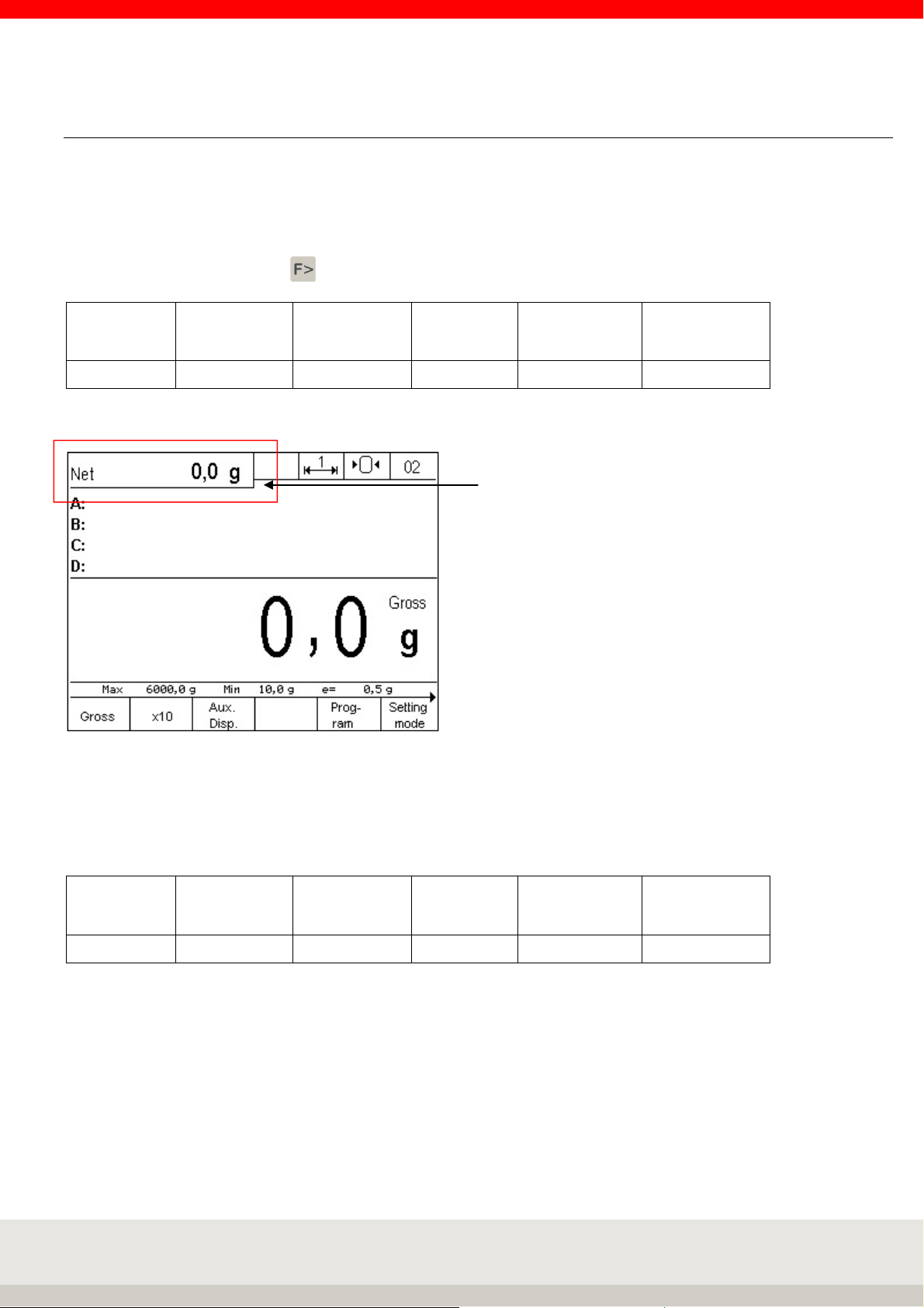
5.10 Auxiliary display
Displays additional information, such as second units, weight values when counting, differences from the
target value, etc.
Activating and deactivating the auxiliary display
Use the function change key to switch to the setting functions level.
Gross x 10
F 1 F 2 F 3 F 4 F 5 F 6
Auxiliary
display
Prog-
ram
Setting
mode
Press the F3 key for the auxiliary display.
Setting the auxiliary display
To set the function of the auxiliary display, first switch to the setting functions level with the function change
key.
Gross x 10
F 1 F 2 F 3 F 4 F 5 F 6
Press the F6 Setting Mode key.
Use the arrow keys F3 and F4 to move to the Terminal item in the list and select it by pressing the F6 "
Continue " key.
Now move to Display with the arrow keys and select it with the F6 " Continue " key.
Now select the submenu Auxiliary display by pressing the arrow keys and the F6 " Continue " key.
Auxiliary
display
Prog-
ram
Setting
mode
Page 43

43
When you call the submenu Auxiliary display, the system displays a list of possible applications:
You can move in the list with the arrow keys F3 and F4.
Functions of the auxiliary display
The following function states can be set in the submenu auxiliary display:
> Second unit
> Tare value
> x10 Resolution
> Gross/net
> Current weight
> Reference quantity
> Reference weight
> Setpoints
> Difference to setpoint
> Signal light
Note: the setting of the function must correspond to the user program!
The factory setting of the auxiliary display is the second unit.
Page 44
44
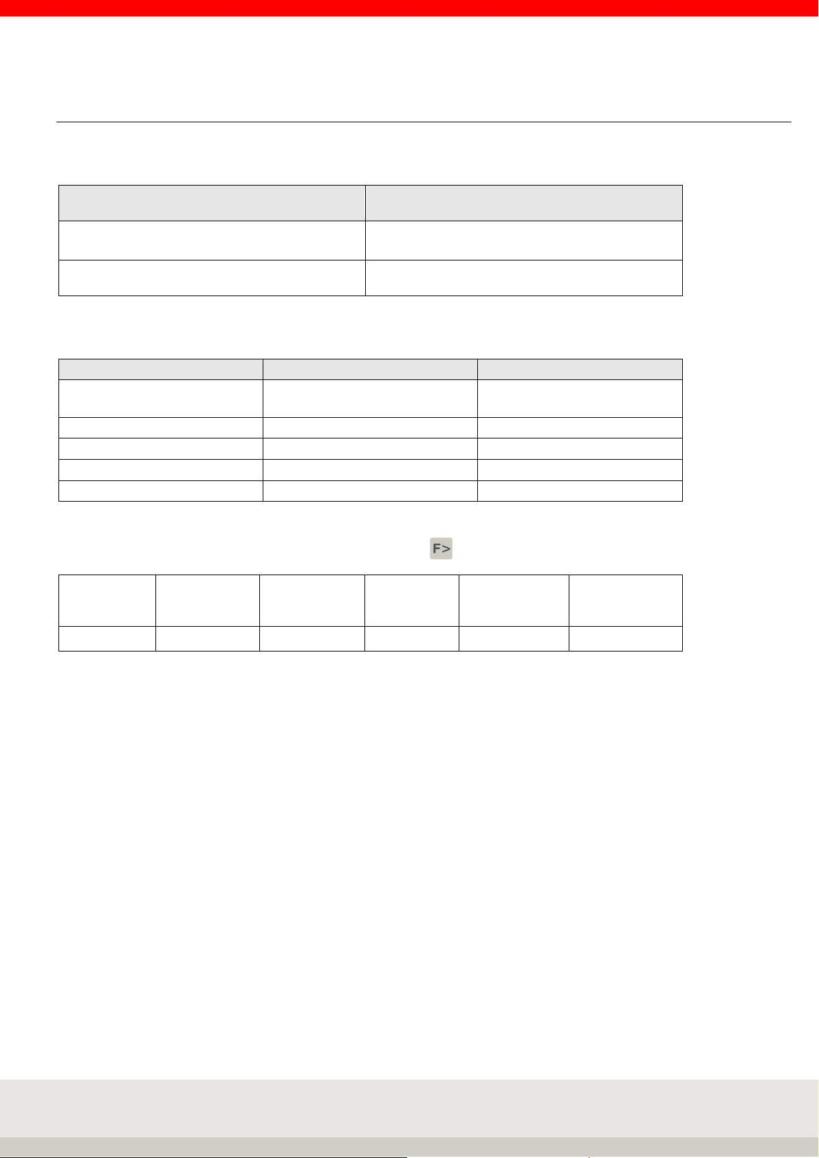
5.10.1 Second unit
The second unit is defined in the setting mode for each connected scale. The following second units are
stored as standard:
Calibrated unit Second unit
kg g
g kg
The following units are available:
Unit Abbreviation Conversion to g
Gram /
Kilogram
Tons t 1.000.000 g
Pound lb 453,59237 g
Milligram mg 0,001 g
Ounce oz. 28,349523125 g
To select the second unit, use the Function change key to switch to the setting functions level.
g /
kg
1 g /
1.000 g
Gross x 10
F 1 F 2 F 3 F 4 F 5 F 6
Auxiliary
display
Prog-
ram
Setting
mode
Press the F6 Setting Mode key.
Use the arrow keys F3 and F4 to move to Scale in the list and select "Continue" by pressing the F6 key.
Then press the F6 Continue key to select Scale parameters.
Use the arrow keys F3 and F4 to move to Second unit in the list and select it by pressing the F6 „Continue "
key.
Page 45

45
You can move in the list with the arrow keys F3 and F4. Press F6 "Apply" to define the second unit.
After selecting the second unit, press F1 "End" to return to the weighing mode.
Page 46

46
5.11 Organisation data (Identifier)
Organizational data is used to assign identification characteristics when documenting weighing operations,
for example, article number, vendor, scale operator.
They are available in all application programs.
The 3025 display unit has 4 organizational data memories.
Each memory has
> a freely selectable designation, e.g. "Article no.". (up to 12 characters, database up to 18 characters).
> a freely selectable content e.g. "1234" (up to 35 characters, database 6x35 characters).
The name is entered in the setting mode, the content in the respective weighing mode. The name and
content can be entered alphanumerically using the numeric keypad.
Four keys to are available for calling up the organizational data memory
Description
Input Designation
First enter the names (max. 12 characters) for the required organizational data memories in the setting
mode:
Call up the setting mode by pressing the F6 key in the Setting functions key level.
Use the arrow key to highlight F4 Terminal, F6 Next.
Use the arrow key F4 to select Organisation data, F6 Continue.
Designation A ORG to D ORG can now be called up and the designation assigned in the input field.
Attention!
An organizational data memory is only activated by assigning a name! Only activated organization data
memories can be called up via the keys A ORG to D ORG.
In the application programs, the names of all activated organizational data memories are then displayed in
the information field under Program settings in the Information field, depending on the setting of the display.
Content
Page 47

47
Input Content
In weighing mode, press the Org button to enter the contents for the organizational data stores. Enter the
content data alphanumerically using the keyboard.
(max. 35 characters). Confirm by pressing the F6 key.
The name and content are now added to the weighing result for identification purposes.
The contents of the organizational data memory are retained until they are overwritten or deleted.
Printout
The "A Org", "B Org", "C Org" and "D Org" keys are used in conjunction with the F6 key to trigger printing if a
print image is stored. Only organizational data containing an entry will be printed.
Displaying the content
Press the corresponding ORG key.
Deleting the contents
Press the corresponding ORG key, then press the CL key, then press the F6 key, or press the CL key to delete
all ORG data terminals (ORGA to ORGD) from the working memory.
Database for organizational data
The use of the organizational data database is only possible with an optional Soehnle Professional Micro-SD
card. Frequently recalled content can be stored as fixed values in a database and recalled as needed. This
saves the repeated manual input of product names, operators, etc.
Example: "Article" has already been created as the name for the organ data memory A.
In Fixed Values Org Data A, enter the articles to be entered such as "Screws", "Nuts", "Washers", "Dowels", etc.
as an entry.
As designation for the org data memory B "operator" has already been created.
Now enter the possible operators such as "Schmidt", "Müller", "Meier", "Krause", etc. as entries in Fixed values
Org data B.
The fixed values can now be activated from the database at any time with a few simple steps.
Calling up the database for entering and editing the fixed values
Direct access by pressing the Info key and the corresponding ORG key.
Or call up setting functions via the setting mode by pressing the F6 key in the key level.
Use the arrow key to highlight F4 Terminal, F6 Continue.
Use the F4 arrow key to highlight organizational data, F6 continue.
Use the F4 arrow key to highlight Fixed values Org data, F6 Continue.
You can create individual fixed values for each of the four org data memories.
There are 999 memory locations available for fixed values (Soehnle Professional Micro-SD card (high-quality
SLC memory card required)).
Each memory location has org data:
> Three-digit consecutive memory location number
> Freely selectable number (alphanumeric 18 characters)
> Entry 1 (alphanumeric 35 characters)
> Entry 2 (alphanumeric 35 characters)
> Entry 3 (alphanumeric 35 characters)
> Entry 4 (alphanumeric 35 characters)
> Entry 5 (alphanumeric 35 characters)
> Entry 6 (alphanumeric 35 characters)
Page 48

48
Selection of existing fixed values from the database
Scroll with the arrow keys F3 and F4,
Call the desired fixed value with F6 Edit
Editing an existing fixed value from the database
Press F6 to call up editing of the selected fixed value.
Parameter number is highlighted, call via F6 Edit, input via number/alpha keyboard. Accept the input with F6.
(Cancel without accepting the entry with F5 Back.)
Mark the respective parameter entry, call up via F6 Edit, input via numbers/alpha keyboard. Accept the entry
with F6.
(Cancel without accepting the entry with F5 Back.)
Deleting an existing fixed value
Scroll with the arrow keys F3 and F4
Delete the marked fixed value with F2 Delete.
The resulting gap in the consecutive numbering is closed.
Create new fixed value
Press F1 New.
The memory location number is assigned by the terminal. The first number in brackets indicates the free
memory locations, the second number the occupied memory locations.
Parameter number is marked, call via F6 Edit, input via number/alpha keyboard. Accept the entry with F6.
(Cancel without accepting the input with F5 Cancel).
Mark respective parameter entry, call via F6 Edit, input via numbers/alpha keyboard. Accept the entry with F6.
(Cancel without accepting the entry with F5 Cancel).
Exiting the database
Press F5 back to exit the list.
Database maintenance via optional Soehnle Professional user software 3025
For the requirement of a simple and multiple application to the care of the Org data base for the designations
and contents there is the PC - user software 3025.
The user software is connected to the PC via the EDP interface RS232, USB or Ethernet with the respective
connection cable. In addition to the Windows-based user software, the Microsoft Excel spreadsheet software
is also required.
Open database to use the fixed values
Call up the desired organisation data memory with the ORGA - ORGD key.
Press the F1 Database key. Selection within the list:
Scroll with the arrow keys, call the desired fixed value with F6 Apply.
Direct call via memory location or article number.
Use the numeric keypad to enter the memory location or article number to call up the corresponding fixed
value.
You can define whether the memory location or article number is to be called up in the setting mode under
Setting mode / Terminal / Organisation data / Call fixed values.
Display the content for the complete multiline database entry.
Call up the desired organisation data memory with the ORGA - ORGD key.
Press the F2 Info lines key to display the complete contents of the currently active memory.
Page 49

49
5.12 Alphanumeric input
Alphanumeric entries can be made using the combined keyboard. Optionally, simplified input is possible with
the USB interface and the USB adapter cable for PC keyboard 2550.03.027 via a USB - PC keyboard.
Types of input fields
Display fields without write capability
Display/write fields with possibility of numerical input
Display/write fields with alphanumeric input option
Activation of input fields
Situation-dependent via function keys or direct number input. The Input view is activated. Existing values are
displayed.
The name of the input field is displayed in the toolbar. A dimension sign is displayed if the input refers to a
dimension.
Input procedure
Numeric Fields
The digits 0 to 9 can be entered directly using the numeric keypad.
The entry is right-justified. A cursor flashes below the last digit entered.
The C key deletes the digit marked with the cursor, the CL key or the Delete function key deletes the entire
entry. Cancel key terminates input without accepting new input values; existing values are retained. Press the
Accept key to accept the entered value and reactivate the application program.
The setting of whether a decimal point, a decimal point or no decimal point is to be used is made in the
Display/decimal point setting mode. The input field can only be filled up to the specified number of
characters, further entries are not displayed and are not accepted.
Alphanumeric fields
The digits 0 to 9 can be entered directly using the numeric keypad.
The entry is left-justified. The numeric keys are also assigned uppercase letters and special characters in
multiple assignments.
The special character keys (,./) and (+-) are also available.
If you press a number key again within one second after pressing it, the characters assigned to the key are
activated in a rolling fashion. If no further key is pressed within one second, the character called up is
accepted and the cursor moves one position forward.
Numeric entries can be made directly on top of each other without waiting as long as a digit is not called
several times in succession. A cursor flashes below the position to be entered.
The cursor can be moved with the arrow keys.
The C key deletes the last character to the left of the cursor or the character under which the cursor flashes,
the CL key deletes the entire input.
Cancel key terminates the input without accepting new input values, existing values are retained. Press the
Accept key to accept the entered value and reactivate the application program. The input field can only be
filled up to the specified number of characters, further entries overwrite the last character. All alphanumeric
entries can also be made using the optional external PC keyboard.
Page 50

50
Key lock active
5.13 Key lock
Single, multiple or all keys can be locked on the keyboard.
Lock keys
Call up Terminal / Keypad / Keypad keylock in the setting mode.
The keyboard is shown schematically in the display. By pressing the key, the status of the key can now be
changed from open to locked and vice versa.
Display view keylock
Locked keys are marked with a cross in the display.
Accept and activate the lock by pressing the Enter key for 3 seconds.
The locked keys are now deactivated, the symbol for key lock appears in the toolbar.
The key lock remains even after switching off.
Cancel key lock
Call up Terminal / Keypad / Keypad keylock in the setting mode.
The keyboard is shown schematically in the display. Locked keys are marked with a cross in the display. By
pressing the key, the status of the key can be changed from locked to open and vice versa.
Accept and activate the change by pressing the Enter key for 3 seconds.
If no more keys are locked, the symbol for key lock disappears from the toolbar.
Note: If access to the setting mode is no longer possible by locking keys, this access can be restored by
pressing the F1 and F6 key combinations for 5 seconds. However, this does not release the key lock, but only
temporarily overrides it for access to the setting mode. After leaving the setting mode, the keypad lock is
reactivated.
Page 51

51
5.14 User password
Access to the setting mode and program selection can be blocked by assigning an individual password to
prevent unauthorized persons from making changes.
Call up Terminal / User password in the setting mode.
> Select New/Edit, in the input field that opens you can assign an alphanumeric password of up to 8
characters, then accept it with F6.
> Select Clear to delete a password and to enable access again.
If the password is forgotten, you can access the setting mode by entering the word "CLEAR" and change or
delete the password.
5.15 Login function / Process start function
This function can be used as login function or start function in processes.
When the terminal is activated, it prompts you to log in after it has been switched on,
or call and exit with the following keys:
> Login Call or start by pressing the Enter key for 3 seconds.
> Logout or end by pressing the C button for 3 seconds.
Details for the dialog and the commands of the EDP data communication can be found in the interface
description 470.508.090.
Activating and Setting
In the Terminal / Login function setting mode, different variants can be user-defined, ranging from a simple
process start query to a password query with monitoring by an external IT system.
Setting parameters Login function / process start function
> Activation
> Password request
> Create/change password
> Delete password
> Enter login text
Activation login function (registration)
Call up setting mode by pressing the F6 key in the setting functions key level.
Use the arrow key to highlight F4 Terminal, F6 Continue.
Use the arrow key to highlight F4 Login function, F6 Continue.
Continue with F6 to the activation, then with the arrow key F4 to on and with F6 Accept.
For the functions start, login and password query, the setting with on must be activated.
Also for the application of a monitoring by the external EDP.
Page 52

52
After switching on the terminal or the login call via the Enter key, the query window login appears.
With key F6 OK the registration is activated and a data record with the confirmation of registration is sent,
afterwards the terminal is in weighing mode.
Press F5 Cancel to display the security prompt Cancel login?
Press keys F4 to F6 NO to return to the Login for a new login query window.
With keys F1 to F3 YES the logon is deactivated and an EDP data record with the logon rejection is sent, then
the terminal is in weighing mode.
Activation of password query (external EDP query)
Call up setting mode by pressing the F6 key in the setting functions key level.
Use the arrow key to highlight F4 Terminal, F6 Next.
Use the arrow key to highlight F4 Login function, F6 Next.
Use the arrow key F4 to highlight the password request, F6 to proceed to the password request, then use the
arrow key F4 to select on and press F6 to accept.
For the password request function, the login function setting must be activated.
Without the internal password system in Terminal 3025, only an external EDP password is requested, sent
and released.
Page 53

53
After switching on the terminal or the login call via the Enter key, the query window Login appears.
With key F5 Cancel you get to the menu Security question Cancel login?
Press F6 OK to display the password prompt.
Enter the required password using the keyboard and confirm with the F6 key.
The password with the command code is sent to the computer for verification and release and the hourglass
appears in the display. Within 5 seconds the computer must release the password, if the password release
does not come within this time the security question Login Cancel? appears. Or if an incorrect password is
confirmed (display message Error 02 Incorrect password), the password query is repeated.
If the F5 Cancel key is pressed in the password query, the Login query window appears on the display with its
query sequence.
Page 54

54
Create/change password (internal terminal password)
The Login function and Password query settings must be activated for the internal password query function.
Call up the setting mode by pressing the F6 key in the Setting functions key level.
Use the arrow key to highlight F4 Terminal, F6 Next.
Use the arrow key to highlight F4 Login function, F6 Next.
Mark with the arrow key F4 Create/change password, F6 Continue into the Create/change password:
Enter the desired password with max. 35 digits and confirm with F6.
Comments:
After entering an internal password, there is no longer an external EDP password query.
When creating an internal terminal password, the password is always requested in the Login function area. If
the password is forgotten, the Login function area can be accessed by entering CLEAR without a password.
After the terminal has been switched on or the login has been called up using the Enter key, the Login query
window appears.
With key F5 Cancel you get to the menu Security question Login Cancel?
Press F6 OK to display the password prompt.
Page 55

55
Enter the required password using the keyboard and confirm with the F6 key.
The entered password is checked:
If entered correctly, the computer record will be sent with the confirmation of registration and the terminal
will then be in weighing mode.
If the entry is incorrect, the display message Error 02 Incorrect password appears briefly and then the
password query appears again.
If the F5 Cancel key is pressed in the password query, the Login query window appears in the display with its
query sequence.
Delete password (internal terminal password)
Call up setting mode by pressing the F6 key in the setting functions key level.
Use the arrow key to highlight F4 Terminal, F6 Next.
Use the arrow key to highlight F4 Login function, F6 Next.
Password prompt, internal terminal - Enter the password and confirm with the F6 key.
If the password is forgotten, you can access the Login function area by entering CLEAR without a password.
Use the arrow key F4 to highlight Delete password, F6 Continue.
The internal password is deleted.
Enter login text
The text for the Login query window can be individually defined and set.
For example: "Start process" or "Start weighing procedure".
Press the F6 key in the Setting functions key level to call up the setting mode.
Use the arrow key to highlight F4 Terminal, F6 Next.
Use the arrow key to highlight F4 Login function, F6 Next.
Use the F4 arrow key to highlight Enter login text, F6 Continue.
Enter login text with max. 35 digits and confirm with F6.
Without entering the login text, the factory setting "Please log in" is used.
Page 56

56
5.16 SD - card data backup
On the optional Micro SD card (Alibi memory) it is possible to save the setting parameters,
to reset the data and functions at the terminal at a later time.
Contents for data backup
All setting parameters (user) and the program selection of the terminal are saved.
The scale/adjustment parameters (ECAL) of the measuring points and the printouts are not saved.
Settings for data backup
In the Setting mode / Terminal / SD card data backup there are the following functions or selections.
> Import
> Export
> Export for automatic import
After the personal settings have been made, one of the two export functions must be executed so that the
Import function can be executed later.
Import
In the SD card data backup menu, the current user settings from the micro SD card are reloaded into the
terminal by accepting F6 Continue. The security question Import with the function keys F1 to F3 YES the data
transfer from the micro SD card to the terminal is executed, with the function keys F4 to F6 NO no data
transfer from the micro SD card to the terminal takes place.
Export
In the SD card data backup menu with the selection Export, the current user settings are saved from the
terminal to the SD micro card by the transfer F6 Next.
This data backup is only for the manual import function.
Export for automatic import
In the SD card data backup menu with the selection Export for automatic import, the current user settings are
saved on the micro SD card and in the event of a software problem, the setting parameters are automatically
reloaded.
This data backup is for the automatic or manual import function.
Page 57

57
6 APPLICATION PROGRAMS
The various application programs of the Soehnle Terminal 3025 offer you comprehensive solutions for your
weighing tasks.
In the setting mode, you can adapt the application programs to your specific requirements. For more
information, refer to the respective chapter Settings in Settings Mode.
The following application programs are available:
> Weighing and taring
> Totalising and picking
> Counting
> Checking
> I/O port programming
6.1 Selection of application programs
Switch on the terminal.
After the power-on routine, the terminal will automatically start the application program that was last
activated.
To select another application program, use the function change key to switch to the Setting functions
level.
6.2 Function keys
Level Setting functions
Gross x 10
F 1 F 2 F 3 F 4 F 5 F 6
Auxiliary
display
Prog-
ram
Press the F5 Program key. You are now in the Programs selection menu.
Setting
mode
Mark the user program with the arrow keys F3 up and F4 down, then confirm with the F6 key.
Page 58

58
6.3 Navigation in the application programs
The function keys F1 to F6 are available for controlling the functions.
They assume different functions depending on the program and situation.
The respective function is shown on the display in the function bar.
Depending on the program, the function keys are assigned in up to 4 levels, the change through the levels
takes place rolling with the function change key.
Meaning of the function keys
↑ Move the marker up in the list.
↓ Move the marker down in the list.
End Exiting the setting mode
Continue Call of the marked menu item
Back Return to superordinate level
Cancel Return without accepting a change
Delete Deleting an item with a return jump
Accept Acceptance of an entry or change
→ Cursor to the right
← Cursor to the left
6.4 Special programs
In addition to the standard user programs, it is also possible to program sequences according to your special
requirements in the factory.
The following special programs are available: compound wheel load scales, price labelling and others.
Please do not hesitate to contact us.
Telephone: +49 7191 34 53-220
Telefax: +49 7191 34 53-211
E-Mail: info@sis.gmbh
Page 59

59
6.5 Weighing and Taring
Basic weighing function, determination of gross and net weights
Note: The following description of the tare functions applies to the factory settings of the options
> Auto tare in position off
> Tare totalling in position, i.e. new tare overwrites old tare
Selection of options in setting mode scale menu
6.5.1 Function keys
The function keys F1 to F6 are available for controlling the functions. These are assigned in 2 levels, the
change between the levels is made by the function change key .
1. Level Tare functions:
Tare
fix
F 1 F 2 F 3 F 4 F 5 F 6
Add
tare
Prov.
tare
Multi
tare
Accept
fixed
2. Level Setting functions:
Gross x10
F 1 F 2 F 3 F 4 F 5 F 6
Auxiliary
display
Prog-
ram
6.5.2 Display view
Basic view weighing
Setting
mode
Page 60

60
Hint: To additionally display, for example, the tare weight or a second unit, you can activate an additional
auxiliary display by pressing the F3 key. You can set the value to be displayed in the auxiliary display in the
setting mode under Setting mode / Terminal / Display / Auxiliary display.
Illustration: Auxiliary display with tare weight
6.5.3 Display information field
In the Setting mode / Program settings / Weighing + taring / Display information field, you can set which data
are displayed in the information field.
The following options are available:
> Factory default: Change between the individual functions used, e.g. switching functions outputs
and inputs and organizational data memory.
> IO control: Continuous display of output and input states.
> Organizational data + database: Continuous display of the organizational data memory.
> Fixed tare values: Continuous display of the activated fixed tare value memory.
> Show barcode: Continuous display of the scanned barcode.
> Code128 weight value: Display bar code128 with the current stability weight value.
Display Information field with setting of fixed tare values
Page 61

61
6.5.4 Weighing without taring
Place the weighing piece on the scale, the weight is displayed with the message Gross.
6.5.5 Manual taring
Determine and tare an unknown container weight.
Place the empty container on the scale. Press the key .
The tare value is stored, the weight display goes to zero and the weight is displayed with the message Net. If
the scale is unloaded, it displays the tare weight with a negative sign.
Pressing the key again overwrites the existing value, i.e. a new tare weight on the scale is stored.
It can be tared indefinitely until the maximum load is reached. The tared weight reduces the maximum
weighing range accordingly.
Clear tare by overwriting with a new tare or by pressing or key .
To display the tare memory, press the key , then the key . Press F2 Delete to delete the tare
memory. F5 Cancel terminates the tare memory display without making any changes. If you want to change
the value of the tare memory, you can enter a new value using the numeric keypad and store it in the tare
memory as a manual tare entry by pressing F6.
6.5.6 Taring with manual tare input
Taring a known container weight, e.g. when the container on the scale is full.
Enter the known tare weight using the numeric keypad and confirm your entry by pressing the F6 Enter key
or the .
The entry is stored in the tare memory and the tare weight is subtracted from the weight display; the weight
is displayed with the message Net. If the scale is unloaded, it displays the tare weight with a negative sign.
Clear tare by overwriting with a new tare or by pressing or key .
To display the tare memory, press the key , then the key .
Here you can delete the tare memory by pressing F2 Delete. F5 Cancel terminates the display of the tare
memory without any changes. If you want to change the value in the tare memory, you can enter a new value
using the numeric keypad and store it in the tare memory as a manual tare entry by pressing F6.
Page 62
62
6.5.7 Multiplicative tare
Taring several containers of the same weight with a known tare weight.
Press the F4 Multi Tare key in the Tare functions level.
Place a container on the scale or enter the known tare weight using the numeric keypad.
Press the F6 key to confirm.
Enter the number of containers using the numeric keypad.
Confirm with the F6 Enter key.
The entry is stored in the tare memory and the total tare weight is subtracted from the weight display. The
weight is displayed with the message Net. If the scale is unloaded, it displays the tare weight with a negative
sign.
Clear tare by overwriting with a new tare or by pressing or key .
To display the tare memory, press the key, then the key.
Here you can delete the tare memory by pressing F2 Delete. F5 Cancel terminates the display of the tare
memory without making any changes. If you want to change the value of the tare memory, you can enter a
new value using the numeric keypad and store it in the tare memory as a manual tare entry by pressing F6.
6.5.8 Additive tare
Taring of several, even different, containers with known tare weight.
Press the F2 Add Tare key in the Tare functions level.
Enter the known tare weight of the first container using the numeric keypad.
Confirm with the F6 Enter key. Repeat the procedure for the remaining containers.
The tare values are stored in the tare memory and the total tare weight is subtracted from the weight display;
the weight is displayed with the message Net. If the scale is unloaded, it displays the tare weight with a
negative sign.
Clear tare by overwriting with a new tare or by pressing or key .
To display the tare memory, press the key , then the key .
Here you can delete the tare memory by pressing F2 Delete. F5 Cancel terminates the display of the tare
memory without making any changes. If you want to change the value of the tare memory, you can enter a
new value using the numeric keypad and store it in the tare memory as a manual tare entry by pressing F6.
Page 63

63
6.5.9 Provisional tare
Unknown tare values are added to the existing tare memory; the net value remains unchanged.
Press the F3 Prov. Tare key in the Tare functions level. Place the additional tare weight on the scale. Confirm
with F6 Apply.
The additional tare weight has been stored in the tare memory; the net value remains unchanged.
Repeat the procedure for additional tare values.
The weight is displayed with the message Net. If the scale is unloaded, it displays the tare weight with a
negative sign.
Clear tare by overwriting with a new tare or by pressing or key .
To display the tare memory, press the key , then the key .
Here you can delete the tare memory by pressing F2 Delete. F5 Cancel terminates the display of the tare
memory without any changes. If you want to change the value in the tare memory, you can enter a new value
using the numeric keypad and store it in the tare memory as a manual tare entry by pressing F6.
6.5.10 Automatic taring
Automatically tares the first weight value on the scale.
Activate the auto tare function for the desired measuring point in the setting mode under
Scale / Scale parameters / Auto tare with the setting on.
Place an empty container on the empty scale.
At stability, the first weight value is stored in the tare memory and subtracted from the weight display. The
weight is displayed with the message Net.
During automatic taring, the message "Auto tare active" appears. If the scale is unloaded, the tare memory is
automatically cleared and the message "Auto tare active" appears in the display. The scale returns to the
gross display.
You can delete auto tare with the scale loaded by pressing the or keys.
The Auto-Tare function is activated automatically when the scale is unloaded and loaded again.
To display the tare memory, press the key , then the key .
Here you can delete the tare memory by pressing F2 Delete. F5 Cancel terminates the display of the tare
memory without any changes. If you want to change the value in the tare memory, you can enter a new value
using the numeric keypad and store it in the tare memory as a manual tare entry by pressing F6.
Combinations of auto tare with other tare functions:
> Multiplicative tare
The first large container placed on the scale is tared by Auto-Tare. Identical sub packages are then
tared with multi-tare.
> Additive tare
The first large container placed on the scale is tared by Auto-Tare. Then, different sub packages with
a known tare are tared by Add-Tare manual entry.
> Provisional tare
The first large container placed on the scale is tared by Auto-Tare. Subsequently, different sub
packages with unknown tare are tared with intermediate tare.
Page 64

64
6.5.11 Fixed tare memory
Known tare weights can be stored in a power-fail-safe memory and called up as required. You can store 999
reference weights in a fail-safe memory.
Each memory location has:
> three-digit sequential number
> Designation (alphanumeric max. 18 digits)
> Tare value
a) Calling up the list of fixed tare values to edit the fixed values:
Press key and then F1 Tare Fix.
Selection of existing fixed values from the list
Scroll with the arrow keys F3 or F4 until the desired memory location is reached, accept the desired fixed
value with F6 Edit.
Direct call via article number or memory location number. Use the numeric keypad to enter the article number
or memory location number. You can define whether the article number or memory location number is called
up in the setting mode. The entry of the article number as a search criterion is left-justified, the entry of the
memory location number as a search criterion is right-justified. Accept the desired fixed value with F6 Edit.
Editing an existing fixed value from the list
Press F6 to call up editing of the selected fixed value.
Parameter Name is highlighted, call via F6 Edit, input via numeric/alpha keyboard.
Input with F6 Accept, abort without accepting the input with F5 Abort.
Parameter Tare value is highlighted, call via F6 Edit, input via digits/alpha keypad.
Input with F6 Accept, abort without accepting the input with F5 Abort.
Delete an existing fixed value
Scroll with the arrow keys F3 and F4.
Delete the marked fixed value with F2 Delete. Press F1, F2 or F3 to confirm with YES Delete. By pressing the
keys F4, F5 or F6 with NO the process can be aborted.
The resulting gap in the consecutive numbering is closed.
Creating and saving a new fixed value
Press F1 New.
The memory location number is assigned automatically by the terminal.
The first number in brackets indicates the number of free memory locations, the second number indicates
the number of free memory locations that can be assigned by
tare fixed values to occupied memory locations.
Parameter name is highlighted, call via F6 Edit, input via numeric/alpha keypad.
Input with F6 Accept, abort without accepting the input with F5 Abort.
Parameter Tare value is highlighted, call via F6 Edit, input via digits/alpha keypad.
Input with F6 Accept, abort without accepting the input with F5 Abort.
Exit the Fixed values list
Press the F5 Back key to exit the list.
Page 65

65
b) Calling up the list of fixed tare values for taring:
Press the F1 Tare Fix key in the Tare functions level. The display shows the last fixed tare value called up.
Selection within the list
Scroll with the arrow keys.
Call the desired fixed value with F6 Accept.
Direct call via memory location number.
Enter the memory location number using the numeric keypad.
Direct call via barcode or EDP
(See chapter 7.10 Bar code management for information or ask your Soehnle Industrial Solutions service
partner).
Note
If the function read-only memory call via barcode is activated and one is called that is not contained in the
fixed memory, the error message "Error 83 - Fixed value not available" appears. You return to the weighing
mode and the selected function is deleted.
Delete Fixed tare value
To delete the tare value and the designation from the working memory, press the CL key..
6.5.12 Error messages during taring
Error 06: Taring not possible.
Possible causes:
> Empty scale,
> Scale in overload or underload,
> Tare manual input with tare value over maximum load,
> The scale shows a negative weight value.
6.5.13 Display options with the Info key
Pressing the button gives you the following options:
> F1 Tare fix
Display of stored tare fixed values (Tare-Fix memory).
> Tare key
Display of the current tare weight in the tare memory.
After pressing the key , press the key .
Page 66

66
6.5.14 Transfer of current values to the fixed memory
To store fixed tare values directly in the fixed memory, first store the tare value or enter the tare manually.
Press the F5 key to confirm. Fix, the value can be stored directly in the Fix memory.
The input window for the fixed tare values appears.
To enter the designation of the fixed tare value, press the F6 Edit key.
Enter the name using the keypad and confirm your entry by pressing the F6 Enter key.
6.5.15 Organizational data (Identifier)
Detailed information on the organizational data can be found in chapter 5.11 on page 46.
Page 67

67
6.5.16 Settings in the Setting Mode
You can use the parameters in the setting mode to adapt the weighing and taring application program to your
individual requirements.
To enter the setting mode, press F6 Setting mode in the Setting functions level and then press F6 Apply to
call up the program settings.
F6 Next calls up the program settings for the selected application program.
1 Weighing and taring
Fixed tare values Editing fixed tare values
Selection of existing fixed values from the list
Scroll with the arrow keys F3 and F4.
Call the desired fixed value with F6 Edit.
Edit an existing fixed value from the list.
Press F6 to call up editing of the selected fixed value.
Parameter Name is marked, call via F6 Edit,
Input via keyboard. Accept the input with F6.
(Cancel without accepting the entry with F5 Cancel).
Further parameters can be edited in the same way.
Deleting an existing fixed value
Scroll with the arrow keys F3 and F4.
Delete the marked fixed value with F2 Delete.
The resulting gap in the consecutive numbering is closed.
Save new fixed value
Press F1 New.
The memory location number is assigned by the device. The first number in
brackets indicates the number of free memory locations, the second number the
memory locations occupied by fixed values.
Parameter Name is highlighted, call via F6 Edit,
Input via keyboard.
Accept the input with F6 Accept.
(Cancel without accepting the entry with F5 Cancel).
Further parameters can be edited in the same way.
Exiting the list Fixed values
Press the F5 Back key to exit the list.
Clear fix tare values Selection Do not execute or Execute
Execute deletes all fixed tare values
ORG A delete fixed values Selection Do Not Execute or Execute
Execute deletes all ORG A fixed values
ORG B delete fixed values Selection Do Not Execute or Execute
Execute deletes all ORG B fixed values
ORG C delete fixed values Selection Do Not Execute or Execute
Execute deletes all ORG C fixed values
ORG D delete fixed values Selection Do Not Execute or Execute
Execute deletes all ORG D fixed values
Page 68

68
1 Weighing and taring
Display Information field Selection of which data is to be displayed in the information field
> Factory default: Change between the individual functions used, e.g.
switching functions outputs and inputs and organizational data memory.
> IO control: Continuous display of output and input states.
> ORG data + database: Continuous display of the organizational data
memory.
> Fixed tare values: Continuous display of the activated fixed tare value
memory.
> Show barcode: Continuous display of the scanned barcode.
> Code128 Weight value: Display bar code128 with the current stability
weight value.
Factory setting: Factory setting
Page 69

69
6.6 Totalising and picking
Totalising
means that the individual positions are weighed one after the other, the weight is added to the totalising
memory and the scale is unloaded again after each individual weighing.
Picking
means that the weighed positions remain on the scale. The weight is added to the total memory and the
scale returns to zero without being unloaded.
It is not permitted to change the measuring point during the picking process.
Selecting Totalising or Picking
is set in the Program Settings setting mode. The selection applies to all connected weighbridges. In the
following, the term "totalising" is used as an example.
Totalising memory for several connected scales
A central totalising memory is maintained for all connected weighing instruments.
Totalising memory capacity
A maximum of 999 bookings are possible in the total memory. The totalising memory must then be erased.
6.6.1 Function keys
The function keys F1 to F6 are available for controlling the functions. These are assigned in 3 levels, the
change through the levels takes place via the function change key.
1. Level Totalising functions:
Total Clear Manual Plus
F 1 F 2 F 3 F 4 F 5 F 6
2. Level Tare functions:
Tare
fixed
F 1 F 2 F 3 F 4 F 5 F 6
Add
tare
Prov.
tare
Multi
tare
Accept
fixed
3. Level Setting functions:
Gross x10
F 1 F 2 F 3 F 4 F 5 F 6
Auxiliary
display
Prog-
ram
Setting
mode
Page 70

70
6.6.2 Display view
After the first totalising process, the display changes from the basic view to the totalising view, provided that
the setting Display information field is set to factory setting.
Hint: To additionally display the 10 times higher resolution x10 or the tare weight, for example, you can
activate an additional auxiliary display by pressing the F3 key. You can set the value to be displayed in the
auxiliary display in the Setting mode under Setting mode / Terminal / Display / Auxiliary display.
Illustration auxiliary display with x10 display
Page 71

71
6.6.3 Display information field
In the Setting Mode / Program Settings / Totalising + Picking / Display Information field can be used to set
which data is displayed in the information field.
The following options are available:
> Factory default: Switch between the individual functions used, e.g. sum memory, organizational data
memory and switching functions for outputs and inputs.
> Total: Continuous display of the totalising memory.
> Last item: Continuous display of the last item.
> IO control: Continuous display of output and input states.
> ORG data + database: Continuous display of the organizational data memory.
> Fixed tare values: Continuous display of the activated fixed tare value memory.
> Show barcode content: Continuous display of the scanned barcode.
> Code128 Weight value: Display bar code128 with the current stability weight value.
Example Setting Display information field on last item:
6.6.4 Tare function
For a description and detailed instructions of the tare function, refer to chapter 6.5 on page 59.
Page 72

72
6.6.5 Operating the totalising function
Use the function change key to call up the totalising functions level.
Plus F6
Press the F6 Plus key to transfer the weight on the weighbridge to the totalising memory. The transaction
counter and the sequential number are incremented by 1.
Before totalling again, the scale must be unloaded to at least the unload factor specified in the setting mode.
A weight value with 0 or a total without a credit is displayed with "Error 55 Place weight on scale" (if the credit
factor = 0, you only need to change the weight).
Gross, tare and net weights are added together.
Hand F5
Press the F5 Hand key to manually enter weight values and piece counts.
The entry is made via the numeric keypad and confirmed by pressing the F6 Enter key.
In the input window, you can switch between the adjusted unit, the second unit and the piece count by
pressing the function-change key . Manual entries are identified in the print document by the designation
Manual.
The transaction counter and the sequential number are incremented by 1. Weight values are added to the
weight total, piece numbers are added separately to the piece total.
Cancellation F4
You can use the F4 Cancel key to reverse or reweigh individual items.
After pressing the Cancellation key, you are prompted either to debit the scale with the weight to be cancelled
or to enter the serial number of the weight to be cancelled.
In advance, you can enter information on the current number by pressing the key combination and F5
Plus. Enter the current number of the item to be cancelled using the numeric keypad and confirm with F6
Accept.
If you do not enter a sequential number, press F6 to store the weight value from the scale. If the scale is
unloaded, you receive the error message Error 46.
Cancellation or back weighing are indicated in the print document by the name Cancellation.
The consecutive number is incremented by one during cancellation; the transaction counter is reduced by
one.
If the transaction counter is set to 0, no further cancellation is possible, indicated by error message Error 48.
Sum F3 or with the CL key
By pressing the F3 Sum key, the summation is completed.
The display now shows the gross, tare, net and piece total, as well as the transaction counter and sequential
number of the last operation.
Page 73

73
6.6.6 Selection options for the totals display
Deleting the totalising memory
The following functions can be assigned to the Total function key in the setting mode:
> Display, print and delete totals
After pressing the Total function key, the totals are displayed for 3 seconds, and the contents of the
memory are printed out and deleted simultaneously. You can then start a new totalising procedure.
> Display totals only
After pressing the function key Total, the user can decide whether the total memory should be deleted
or not. Press the F2 key to clear the totalising memory, then press the F2 key to clear the totalising
memory. Use the F1 to F3 YES keys to clear the totalising memory, while the F4 to F6 NO keys do not
clear the totalising memory.
If you want to continue totalising without deleting the memory, press the F6 Back key.
6.6.7 Relief factor for totalising
(Parameter is not used in the Pick function)
In the setting mode, you can specify that the scale must be unloaded by a certain number of digits between
the placing on the scale of the individual items in the Totalising function. If you do not relieve the load, the
weight value is not stored in the totalising memory and is displayed with the error message Error 55 Place
weight on scale. In this way, you can prevent, for example, duplicate entries being made for one item.
6.6.8 Auto total / pick
The auto total function can be activated in the setting mode.
Then only the first position must be stored with the Plus key; all other positions are automatically stored in
the totalising memory after they have been cleared (only for totalising) and weight has been placed on the
scale.
If auto totalising is interrupted due to cancellation, error message or change of measuring point, auto
totalising must be restarted with the Plus key.
Info: Auto totalising can be defined as a print-triggering condition in the same way as manual totalising (see
section 8 Printing in the 3025 Operation Manual).
With auto batching, a load <5 digits is not automatically accepted; weights < 5 digits can be manually stored
in the pick memory using the F6 Plus key.
6.6.9 Reference scale for totalisation
The total memory can only be determined with one unit and resolution. When several scales (measuring
points) with different settings are used, the parameters of the currently connected scale are used for the
totalising process.
In the setting mode, you can assign the preferred totalising scale function.
The unit and resolution for the totalising memory are always determined with the selected scale number.
Page 74

74
6.6.10 Assigning and deleting the sequential number
Each entry (plus, manual, cancellation) in the total memory is assigned a four-digit sequential number.
The sequential number is not reset in the factory setting.
Optionally, the consecutive number can be reset in the setting mode:
> not active (no reset = factory setting)
> Delete the totalising memory
> Switch off the terminal
> Function key: in the first level of totalising functions, the key F1 current no. delete is activated
with the function.
6.6.11 Item counter
The item counter only counts the actually totalled transactions. For each new transaction with plus, manual
or automatic totalisation, the transaction counter is incremented by 1.
The transaction counter runs up to 999, followed by the error message Error 45.
In the event of a cancellation, the transaction counter is reduced by 1.
The transaction counter is always automatically set to zero when the total is deleted.
6.6.12 Print-triggering keys
Additional keys or functions such as plus, manual, cancellation and total can be used in the totalising /
picking function as print-triggering keys, e.g. for document printing. The prerequisite is that a print image has
been stored for the respective key.
The "Display, print" option must be selected for the totals key in the totals key function setting mode.
and delete" or delete the total using the F2 key in the total termination function.
6.6.13 Display of current totals
Within a summation, you can display the totals values achieved by choosing one after the other
Press the Info key and then the F4 Sum key.
You can clear the totals by pressing the F2 key and the sequential number (if only "Display" is activated in the
totalling key function in the setting mode) or return to the totalling mode by pressing the F6 key.
Page 75
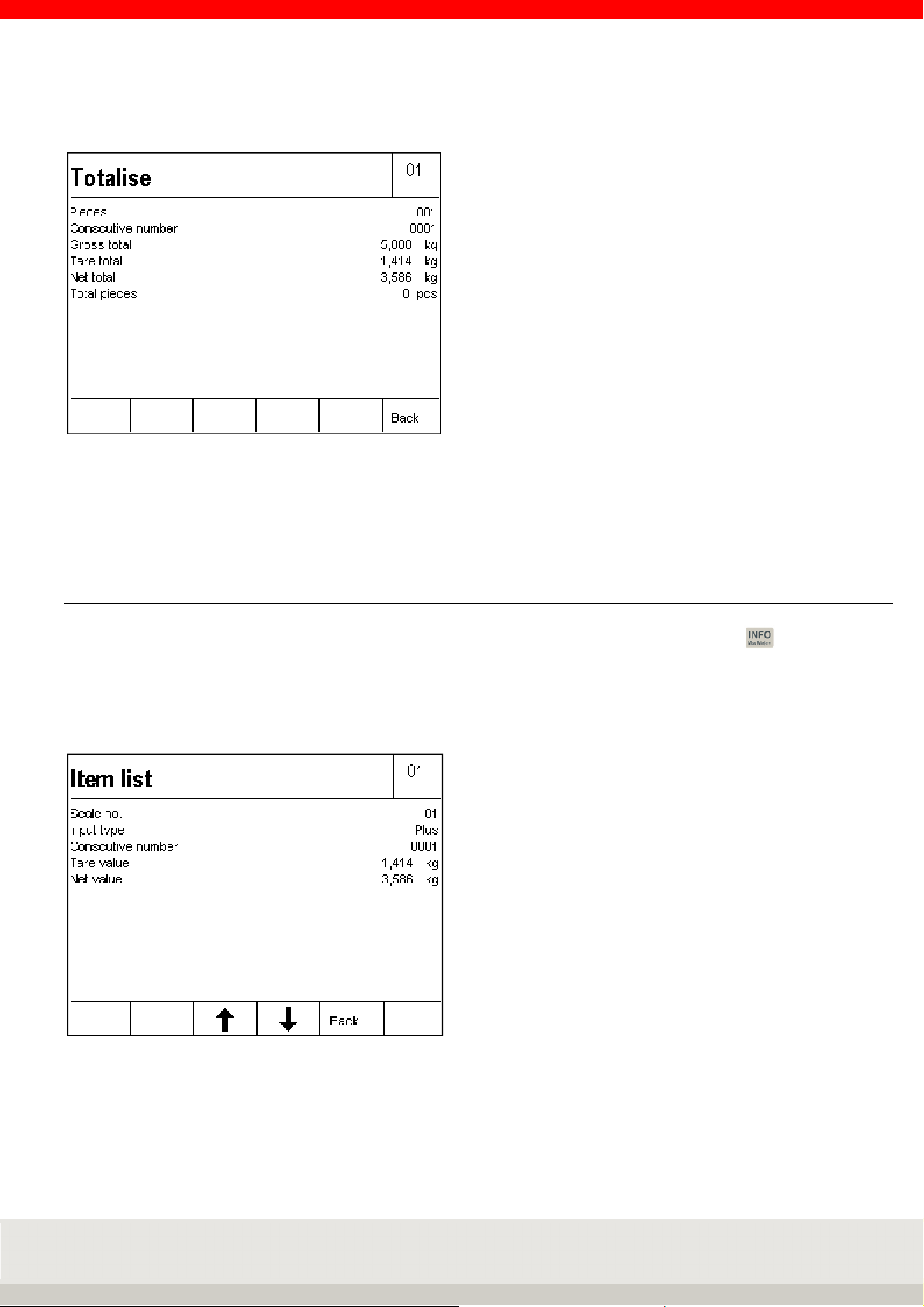
75
Display Current totals view:
Note: Display information field with current totals
In the Setting Mode / Program Settings / Totalising + Picking / Display Information field can be set to sum,
then the sum is always displayed in the information field.
6.6.14 Display individual items
Within a total, you can call up the individual items from the totalising memory by pressing and the F5
Plus key one after the other. The item list starts with the most recent entry.
Use the arrow keys F3 (older entries) and F4 (newer entries) to cycle through the list.
The last 50 entries can be called up.
Press the F5 Back key to exit the display of the individual items and return to the previous display.
Note: Display information field with item list
In the Setting Mode / Program Settings / Totalisation + Picking / Display Information field can be set to last
item, then the last item is always displayed in the information field.
Page 76

76
6.6.15 Display options with the Info key
Pressing the key gives you the following options:
> F1 Tare fix
Display of the stored tare fixed values (Tare-Fix memory).
> F4 Total
Display of the current totals in the totalising memory
> F5 Plus
Displays all items stored in the totalising memory (item list). The individual items can be called up
using the arrow keys (F3/F4).
> Tare key
Displays the current tare weight in the tare memory.
After pressing the key , press the key .
6.6.16 Transfer of current values to the fixed memory
To store fixed tare values directly in the fixed memory, first store the tare value or enter the tare manually.
Page 77
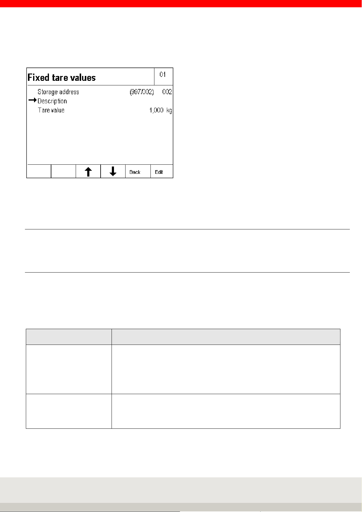
77
By pressing the F5 Apply Fix key, the value can be stored directly in the fixed memory.
The input window for the fixed tare values appears.
To enter the designation of the fixed tare value, press the F6 Edit key.
Enter the name using the keypad and confirm your entry by pressing the F6 Enter key.
6.6.17 Organizational data (Identifier)
Detailed information on the organizational data can be found in chapter 5.11 on page 46.
6.6.18 Settings in the setting mode
With the parameters in the setting mode, you can adapt the application program Totalising and Picking to
your individual requirements.
To call up the setting mode, press the F6 Setting mode key in the Setting functions level and then press F6
Apply to call up the program settings.
F6 Next calls up the program settings for the selected application program.
2 Totalising and Picking
Totalising or Picking Selection of totalling or picking for the following settings.
Totalising means that the individual items are removed from the scale after they
have been stored in the totalising memory.
Picking means that the individual items remain on the scale after they have been
stored in the totalising memory and that the next items are placed on the scale.
Factory setting: Totalising
Reference scale for
totalisation
Selection none, scale xx, scale xx etc.
Which scale no. is used for the resolution of the totalising memory.
If none is selected, the currently loaded scale is always used for the first
totalisation. Factory setting: none
Page 78
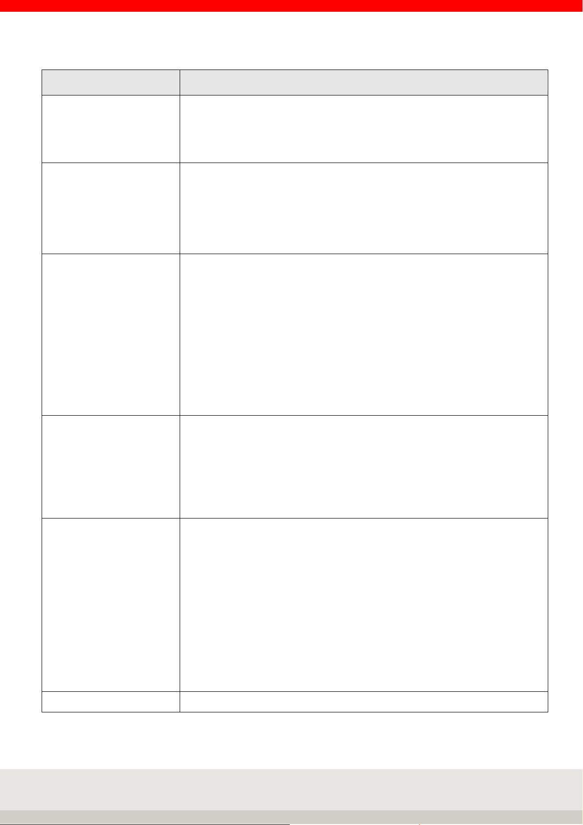
78
ing memory; error message
2 Totalising and picking
Auto total/pick Selection off or on
On means that only the first position at a time needs to be stored by pressing the
Plus key, all other positions are automatically placed on the scale after weighting
and stability is stored in the totalising memory.
Factory setting: Off
Reset consecutive number Selection of the condition under which the consecutive totalling / picking number
is to be reset.
> not active
> Delete total memory
> On/Off
> Function key (activates a separate function key)
Factory setting: not active
Total key function Selection of which functions are to be linked to the sum key
Display totals only
After pressing the function key Total, the total is displayed. The user can then
decide whether the total memory is to be deleted or not.
Press the F2 key to clear the total memory.
Then confirm the confirmation prompt with the F1 to F3 keys and press YES to
print the total.
Total Display/Print/Clear
After pressing the Total function key, the totals are displayed for 3 seconds.
The memory contents are printed out and deleted at the same time. Then
a new totalling operation can be started.
Factory setting: Display/Print/Clear
Clip off factor Input in d via numeric keypad
The number of digits by which the scale/scale must be unloaded during
totalisation so that you can store weights in the totalising memory again. If the
weight is not unloaded, it will not be stored in the totalis
"Error 55 Place weight on scale.
You can enter values between 0 and 30 digits. If you enter 0, you can total the
weight once the stability has been reached.
Factory setting: 15 digit increments
Display information field Selection of which data is to be displayed in the information field
> Factory default: Switch between the individual functions used, e.g.
totalising memory, organizational data memory, switching functions.
> Total: Continuous display of the totalising memory.
> Last item: Continuous display of the last item.
> IO control: Continuous display of output and input states.
> ORG data + database: Continuous display of the organizational data
memory.
> Fixed tare values: Continuous display of the activated fixed tare value
memory.
> Show barcode: Continuous display of the scanned barcode.
> Code128 Weight value: Display bar code128 with the current stability
weight value.
Factory settings: Factory default
Factory setting Execute selection resets all settings to factory settings.
Page 79
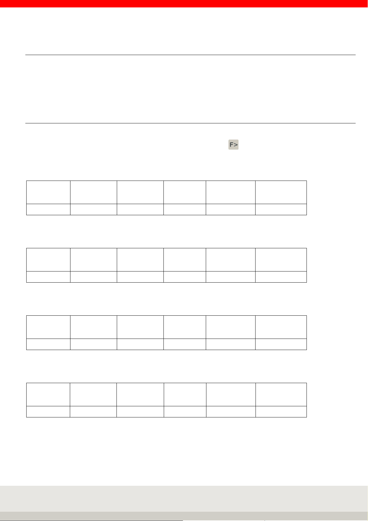
79
6.7 Counting
Counting of parts of the same weight.
The individual part weight (reference weight) is determined from a known small quantity of counted parts.
This is then used as a divisor to determine the number of pieces from the weight of an unknown quantity of
these counted parts.
6.7.1 Function keys
The function keys F1 to F6 are available for controlling the functions. These are assigned in 4 levels, the
change through the levels takes place via the function change key.
1. Level Counting functions:
Ref
10
F 1 F 2 F 3 F 4 F 5 F 6
Ref
Variab
Ref
Weight
Total Clear Plus
2. Level Control functions:
F 1 F 2 F 3 F 4 F 5 F 6
Ref
Stat
Ref
fix
3. Level Tare functions:
Tare
fixed
F 1 F 2 F 3 F 4 F 5 F 6
Add
tare
Prov.
tare
Multi
tare
Accept
fixed
4. Level Setting functions:
Gross x10
F 1 F 2 F 3 F 4 F 5 F 6
Auxiliary
display
Prog-
ram
Setting
mode
Page 80

80
6.7.2 Display view Counting
Hint: To additionally display, for example, the reference quantity, the x10 resolution or the tare weight, you
can activate an additional auxiliary display by pressing the F3 key. You can set the value to be displayed in
the auxiliary display in the setting mode under Setting mode / Terminal / Display / Auxiliary display.
Illustration auxiliary display with reference quantity
Page 81

81
6.7.3 Display information field
In the Setting mode / Program settings / Counting / Display information field you can set which data are
displayed in the information field.
The following options are available:
> Counting: Switching between the individual functions used, counting with the reference weight and
weight value in gross / net, e.g. control light, totalising memory.
> Control display: Continuous display of the traffic light function.
> Total: Continuous display of the totalising memory.
> Last item: Continuous display of the last item.
> ORG data + database: Continuous display of the organizational data memory.
> Fixed values for reference weight: Continuous display of the reference weight memory activated.
> Show barcode: Continuous display of the scanned bar code.
> Code128 Weight value: Display bar code128 with the current stability weight value or counter value.
Example: Setting the display of the information field to fixed values for the reference weight:
Example control display, a traffic light display is available in the information field.
1. Below tolerance 2. Within tolerance 3. Above tolerance
(Target values reached exactly)
6.7.4 Tare function
For a description and detailed instructions of the tare function, refer to chapter 6.5 on page 59.
Page 82

82
6.7.5 Counting function
The reference weight can be determined using the following function keys:
> Function key F1 Ref 10
Reference weight determination from a preassigned reference sample quantity. Place 10 counted
pieces on the scale, then press the F1 Ref 10 key. The scale determines the reference weight and
displays "10 pieces. Parts that have been placed further on the scale are counted continuously. The
standard reference sample quantity "10" can be selected in the Setting mode / Program settings /
Counting under Standard reference pieces. (Chapter 6.7.14).
If, for example, 25 is stored there, the new function key is F1 Ref 25 and 25 pieces must be loaded to
determine the reference weight.
> Function key F2 Ref Variab
Reference weight determination from a freely selectable reference sample quantity. Place a certain
number of reference parts on the scale. Press the F2 Ref Variab key and enter the quantity (1 to 9999)
of the parts on the scale using the numeric keypad. Press the F6 Enter key. The terminal determines
the reference weight and displays the number of pieces on the scale. Parts that have been placed
further on are counted consecutively.
> Function key F3 Ref Weight
Enter a known reference weight. Press the F3 Ref weight key and enter the known reference weight
using the numeric keypad. An existing reference weight is displayed and can be overwritten. By
default, the reference weight is entered in grams. If you want to enter the reference weight in
kilograms, you can change the unit by pressing the key . Confirm your entry with F6 Apply.
The terminal has accepted the reference weight and displays the quantity loaded.
New reference weight
Existing reference weights are generally overwritten by a new reference weight determination or by a fixed
value being transferred from the fixed memory.
Displaying the reference weight
Press the F3 Ref weight key or activate the auxiliary display (see chapter 5.10).
End counting
The counting process is terminated by deleting the reference weight. The reference weight can be deleted by
pressing the F3 Ref Weight and F2 Delete keys or simply by pressing the key . The display shows the
current weight value.
Read-only memory Reference weight (Ref Fix)
You can store 999 counted items in a database that is protected against power failure.
Each memory location has the following entries:
> Three-digit sequential number
> Designation (alphanumeric max. 18 characters)
> Article number (alphanumeric max. 18 digits)
> Reference weight
> Nominal piece count
> Tolerance minus
> Tolerance plus
Page 83

83
a) Call the Ref fix memory to edit the counted items:
Press key and then F2 Ref Fix
Selection of existing fixed values from the list
Scroll with the arrow keys F3 or F4 until the desired memory location is reached, accept the desired fixed
value with F6 Edit.
Direct call via article number or memory location number. Use the numeric keypad to enter the article number
or memory location number. You can define whether the article number or memory location number is called
up in the setting mode. The entry of the article number as a search criterion is left-justified, the entry of the
memory location number as a search criterion is right-justified. Accept the desired fixed value with F6 Edit.
Editing an existing fixed value from the list
Edit the selected fixed value via F6 Edit.
Parameter Name is highlighted, call via F6 Edit, input via keyboard. Accept the entry with F6 (abort without
accepting the entry with F5 Abort).
Further parameters are edited in the same way.
Deleting an existing fixed value
Scroll with the arrow keys F3 and F4 or call up via the article number or the sequential number.
Delete the called fixed value with F2 Delete. Answer the confirmation prompt with YES.
The resulting gap in the consecutive numbering is closed.
Save new fixed value
Press F1 New.
The memory location number is assigned by the device. The first number in brackets indicates the number of
free memory locations, the second number the occupied memory locations.
Parameter Name is highlighted, call via F6 Edit, input via keyboard. Accept the entry with F6 (abort without
accepting the entry with F5 Abort).
Further parameters are edited in the same way.
Exiting the list Fixed values
Press the F5 Back key to exit the list.
b) Calls up the reference weight list for counting:
In Level 2 Control Functions, press the F4 Ref Fix key.
The display shows the last fixed value called up.
Selection within the list
> Scroll with the arrow keys F3 or F4 until the desired memory location is reached,
Accept the desired fixed value with F6 Accept
> Direct call via article number or memory location number
Use the numeric keypad to enter the item or memory location number.
(Determining whether the article or memory location number is called up in setting mode,
entering the article number as a search criterion is left-justified, entering the memory location
number as a search criterion is right-justified) Accept the desired fixed value with F6 Accept
Page 84

84
When the fixed value is called up, nominal quantities and tolerances for the piece check are also accepted, if
saved with .
To delete all stored reference weights, use the "Delete reference weights" function in the setting mode.
Hint
If the function read-only memory call via barcode is activated and one is called that is not contained in the
fixed memory, the error message "Error 83 - Fixed value not available" appears. You return to the weighing
mode and the selected function is deleted.
6.7.6 Totalising and Picking
This function is also available in count mode.
You can use this function to total/pick items of the same unit goods.
The totalising functions are controlled using function keys at the Counting functions level.
Totalising
means that the individual positions are weighed one after the other, the weight in the totalising memory is
added, and the scale is unloaded again after each individual weighing.
Picking
means that the weighed positions remain on the scale.
The weight is added to the total memory and the scale returns to zero without being unloaded.
It is not permitted to change the measuring point during the picking process.
Selecting Totalising or Picking
is set in the Program Settings setting mode.
The selection applies to all connected weighbridges.
In the following, the term "totalising" is used as an example.
Totalising memory for several connected scales
A central totalising memory is maintained for all connected weighing instruments.
Totalising memory capacity
A maximum of 999 bookings are possible in the total memory.
The totalising memory must then be erased.
Page 85

85
Display view
After the first totalisation, the display changes from the Count basic view to the Totalise view if the setting
"Display information field" is set to Count.
Operating the Totalising functions
Use the function change key to call up the Totalising functions level.
> Plus F6
Press the Plus key to transfer the weight on the weighing platform to the totalising memory. The
transaction counter and the sequential number are incremented by 1.
Before totalling again, the scale must be unloaded to at least the unload factor specified in the setting
mode.
A weight value with 0 or a total without a credit is indicated by "Error 55 Place weight on scale". If the
load-relief factor = 0, you only need to change the weight.
Gross, tare and net values and piece counts are totalled.
> Cancellation F5
You can use the Reversal button to reverse or back weigh individual items. After pressing the Cancel
key, you are prompted either to debit the scale with the weight to be cancelled or to enter the current
number of the weight to be cancelled.
Information on the current number via the key combination Info and Plus F5.
Enter the current number of the item to be cancelled using the numeric keypad and confirm with F6
Accept.
If you do not enter a sequential number, press F6 to store the weight value from the scale. If the scale
is unloaded, an error message Error 46 appears. Cancellation or back weighing is indicated in the print
document by the name Cancellation.
The consecutive number is incremented by one during cancellation; the transaction counter is reduced
by one.
If the transaction counter is set to 0, no further cancellation is possible, indicated by the error message
Error 48.
> Sum F4 or with the CL key
Pressing the Total key completes the totalisation.
The display now shows the gross, tare, net and piece total, as well as the transaction counter and
sequential number of the last operation.
Page 86

86
Selection options for displaying the total
Deleting the totalising memory
The following functions can be assigned to the Sum function key in the setting mode:
> Display, print and delete totals
After pressing the Total function key, the totals are displayed for 3 seconds, and the contents of the
memory are printed out and deleted simultaneously. You can then start a new totalising procedure.
> Display totals only
After pressing the function key Total, the user can decide whether the total memory should be deleted
or not.
Press the F2 key to clear the total memory.
If you want to continue totalising without deleting the memory, press the F6 Back key.
Relief factor for totalising
(Cannot be activated during picking)
In the setting mode, you can specify that the scale must be unloaded by a certain number of digits between
the placement of the individual items.
If the weight is not discharged, the weight value is not stored in the totalising memory and the error message
"Error 55 Place weight on scale" appears. In this way, you can prevent, for example, double storage of an
item.
Auto Totalise
The Auto Totalise function can be activated in the setting mode.
In this case, you only need to confirm the first position by pressing the Plus key. All other positions are
automatically added after weight has been reached and stability is stored in the totalis
ing memory.
As long as auto totalising is active, the Plus key is dimmed.
If auto totalling is interrupted due to cancellation, error message or change of measuring point,
then auto totalling must be restarted with the Plus key.
Info: Auto totalising can be defined as a print-triggering condition in the same way as manual totalising.
(see chapter 8 Printing in the manual).
Assigning and deleting the sequential number
Each entry (plus, manual, cancellation) in the total memory increases a four-digit sequential number.
The sequential number is not reset in the factory setting.
Optionally, the consecutive number can be reset in the setting mode:
> not active (no reset = factory setting)
> Delete sum for key
> when switching off
> Function key "Delete current number".
Page 87

87
Item counter
The item counter only counts the actually totalled transactions. For each new transaction with plus, manual
or automatic totalisation, the transaction counter is incremented by 1. The transaction counter runs to 999,
followed by an error message. In the case of reversal, the item counter is reduced by 1.
The item counter is automatically set to zero when the total is deleted.
Print-triggering keys
The Plus, Reversal and Total keys can trigger document printing.
The prerequisite is that a print screen has been defined for the respective key.
The "Display, print and delete" option must be selected for the total key in the Total key function setting
mode.
Display current totals
Within a total, you can display the total values achieved, by pressing the key and then the F4 Sum key
one after the other.
You can delete the totals by pressing the F2 Total key, delete the F1 consecutive no. key F1 (if activated in
the setting mode), or return to the totalling mode by pressing the F6 key.
Page 88

88
Display individual items
Within a total, you can call up the individual items from the total memory,
by pressing the key and the F5 Plus key one after the other. The item list starts with the most recent
entry.
Use the arrow keys F3 (older entries) and F4 (newer entries) to cycle through the list.
The last 50 entries are available.
Press the F5 Back key to exit the display of the individual items and return to the previous display.
Totalising outside tolerance
You can prevent the totalling of quantities that lie outside a specified tolerance range. If the quantity is
outside the tolerance range, the error message "Out of tolerance" appears after you press the Plus key.
To do this, you must switch it off in the setting mode under "Totalising outside tolerance". You define the
target quantity and the permitted tolerance in the piece check mode.
Further information can be found under Check piece
Totalising of different counted parts
You can prevent the totalising of different parts by selecting "Clear total" in the Setup mode to allow a new
reference weight to be determined only after the totalising memory has been cleared.
6.7.7 Reference statistics
Determination of the weight tolerance of counted parts.
The weighing bridge with the finest resolution is used.
The piece weight must be greater than the smallest digit increment of the connected weighbridge.
Unload the scale. Press the F3 Ref Stat key.
The scale shows zero and requests "Place 1st sample on scale".
Place the sample on the scale, the scale takes over, goes to weight value zero and requests the second
sample.
The previous sample remains on the scale.
Repeat the procedure until the desired number of samples is reached.
Press the F6 Enter key to evaluate and display the statistics.
Page 89

89
Example for reference statistics display: Samples 04
Lightest part 24,448 g
Heaviest part 24,750 g
Divergence 0,302 g
Average 24,589 g
Printout of statistics
Press the Print button.
Store the mean value as the reference weight for counting
Press F6 Accept.
Exiting the reference statistics without accepting the mean value
Press F5 Cancel.
6.7.8 Piece control
By the function "piece control" piece goods can be dosed into a container or quantities can be controlled.
Example: You want to fill 1000 counted parts with max. 3 parts tolerance into a container.
Example: You want to check several batches for compliance with the quantity.
To call up the piece check function, you must already be in counting mode, i.e. have defined a reference
weight.
In level 2 Control functions, press the F5 key to select Contr.
Use the numeric keypad to enter the desired piece count, confirm with the
F6 Apply. Enter the accepted tolerance in pieces using the numeric keypad and confirm with the F6 Enter key.
If you want to define the plus and minus tolerance separately, activate / in the setting mode under Program
settings / Counting / +/- Tolerance separated /.
The display switches to the Counting display view, the traffic light function with the special characters is
activated. The corresponding traffic light colour with special characters is displayed on the scale according
to the actual status of the target value.
Control status Control light Special characters
Below tolerance
Within tolerance
Setpoint reached exactly
Above tolerance
yellow
green
green
red
You can also have the difference between the target weight and the + or - sign displayed in the upper lefthand corner of the auxiliary display. Activate the auxiliary display by pressing the F3 key in Level 4
Adjustment Functions.
Display setpoint and tolerance
Press the Info key and then the F3 piece control key.
Page 90

90
Switching points for piece control
If you want to transfer the control values via the interface, e.g. to a control light or to a controller, an I/O card
must be installed in the terminal. This must be activated in the setting mode under Program settings /
Counting / Default IO configuration with Execute. The output signals are assigned as follows:
Switching point Signal
S1 Weight value above tolerance
S2 not active
S3 Weight value within tolerance
S4 Weight value below tolerance
S5 empty signal
S6 Weight value above tolerance
The individual inputs and outputs can be individually adapted.
Data record / impression within or outside tolerance
The release of a data set outside a defined tolerance range can be prevented or accepted. If a data record is
released outside the tolerance range, it is marked with a special character. Enable or disable in setting mode
under Program Settings / Counting / Data record outside tolerance.
Start mode
When the start mode is activated, the scale freezes the value and thus the signal once the activated
switching points have been reached. The scale can then be unloaded without deactivating the switching
point and thus unintentionally starting a new process. Only by pressing the F6 Start key in the Control
functions level is the frozen status released.
Activate the start mode in the setting mode under Program settings / Counting / Start mode.
End piece control
Call up the 2nd level control functions via the key and press key F5 Quantities contrast, then delete via
key F2 Delete or complete deletion via key .
6.7.9 Counting with several weighing bridges
If several scales are connected, the reference weight can be determined and quantities counted on each
scale. For best results, we recommend that you determine the reference weight on the scale with the finest
numeric increment. Select the scale using the scale button.
Once you have determined the reference weight, you can switch to a bulk scale with a higher capacity to be
able to count large quantities using the reference weight determined on the reference scale.
Automatic changeover:
You can define a preferred reference scale in the setting mode.
The system then automatically switches from the quantity scale to the reference scale and back.
Place the reference quantity on the reference scale and press the Ref 10 or Ref Variable key. The display
switches to the preferred reference scale, the reference weight is determined, and then the bulk scale is
activated for quantity determination.
If you do not want the reference weight to be determined in the same way as the reference weight, but also
the reference weight to be counted, switch manually from the mass comparator to the reference scale before
determining the reference weight.
Page 91

91
6.7.10 Counting accuracy
In the setting mode, you can influence the counting accuracy of your scale in the Program settings /
Counting.
> Standard reference sample quantity
The reference sample quantity is set to 10 at the factory.
You can set this quantity between 1 and 99.
For small parts, it makes sense to use a larger number of parts for reference weight determination.
> Minimum reference weight
The counting scale checks whether the total weight of the reference parts falls below a minimum
reference weight. The calculation is based on the smallest digit of the scale multiplied by a value
stored in the setting mode. The factory setting is a factor of 10, i.e. 10 digits. Values between 1 and
50 are possible.
If the minimum reference weight is not reached or if the calculated reference weight is smaller than
the numeric increment of the scale (in the case of multiple-range scales, the smallest numeric
increment), the quantity determined is indicated in the display by an asterisk to inform the user.
If a reference sample falls below 10% of the smallest numeric increment of the connected scale,
the reference weight cannot be determined for this sample; "Error 04 Reference weight too small"
appears in the display. These parts should be counted using a scale with a smaller numeric
increment.
Example of a scale with 1 g digits:
The factory setting is 10 d = 10 g for the total weight of the reference parts.
If you reduce the factory setting to 5 d, the scale will accept 5 g as the minimum weight for the total
weight of the reference parts. If you increase the factory setting to 20 d, the scale will assume a
minimum weight of 20 g for the total weight of the reference parts.
> Optimization Ref. (reference weight optimization)
The reference weight of a batch, determined by the reference weight calculation from e.g. 10 or 20
parts, is usually not the "real average weight" of a part from the entire batch. The lightest and heaviest
parts are always somewhere in a batch. The difference between the two parts is the manufacturing
tolerance, which influences the counting accuracy.
The determination of the reference weight at the beginning of a counting process, e.g. from 10 or 20
parts, is carried out from a "randomly" taken number of parts, which naturally differ from the "real
average weight" (reference weight). Therefore, it would be desirable for the accuracy of the counting
results if the reference weight could be determined not only once at the beginning of the counting
process, but often during the current counting process, from an ever-increasing number of parts.
The solution to this problem is reference weight optimization.
After the reference weight has been determined using a reference quantity, for example 10 or 20
parts, the reference quantity (first quantity) appears in the display. Further parts are now placed on
the display. When the scale has stabilized, a new reference weight is determined with the quantity
shown in the display and a new, "more average reference weight" is determined. You can repeat this
procedure as often as you like as long as the following rule is observed:
Page 92

92
Do not place more parts on the scale than are already on it.
The reason for this is that a reference weight calculation may only be performed if the quantity on the
scale is exactly correct. It would make no sense to calculate the reference weight from 10 parts, add
1,000 parts and then optimize with 1,010 parts. There is a danger that due to the manufacturing
tolerance of the parts or the uncertainty of measurement of the scale, for example, 1,009 or 1,011
parts are on the scale and a reference weight optimization would lead to a completely incorrect
reference weight. Therefore, the reference weight is not optimized in this case. However, the
reference weight optimization function remains active. If you place more parts on the scale than are
allowed for reference weight updating and do not initially optimize the reference weight, you can
remove them again. As soon as the scale detects the smaller quantity, the reference weight is
updated again.
Reference weight updating is switched on and off in the setting mode under Program settings /
Counting / Optimise ref. The percentage value determines up to which percentage of the maximum
load of the scale is to be optimized. Example: 0 = off, 50% = 30kg for a scale with 60kg maximum
load, 100% = 60kg for a scale with 60kg maximum load.
Example of reference weight updating:
Reference
quantity
10 parts 20 counted parts 40 counted parts 80 counted parts 160 counted parts 320 counted parts
1.
Ref. optimization
for currently 10
parts on the scale,
place additional up
to max.
2.
Ref. optimization
for the current 20
parts on the scale,
place additional
parts on the scale
up to max.
3.
Ref. optimization
for currently 40
parts on the scale,
place additional
parts on the scale
up to max.
4.
Ref. optimization
with currently 80
parts on the scale,
additional loading
of up to max.
5.
Ref. optimization
160 parts on the
scale at the
moment,
additionally place
up to max.
> ADD- Mode
If the minimum reference weight is not reached, the parts are requested until the minimum reference
weight is reached. The scale calculates the reference weight after the requested parts (add xx pieces)
have been placed on the scale.
Example for reference weight determination in ADD mode:
Smallest digit of the scale: 1 g
Set minimum load: 10 d
Results in min. load for reference weight determination: 10 g
Example for part weight: 0,8 g
Reference quantity: 10 pieces
Results in a weight value for reference weight calculation: 8 g
Difference to set minimum load: 2 g
ADD Mode requests parts: 3 pieces
Page 93

93
6.7.11 Display options with the Info key
Pressing the button gives you the following options:
> F1 Tare fix
Display of stored tare fixed values (Tare-Fix memory).
> F2 Ref fix
Display of stored reference weights (Ref-Fix memory)
> F3 Check pieces
Display of the current setpoint with tolerance
> F4 Total
Display of the current totals in the totalising memory
> F5 Plus
Displays all items stored in the totalising memory (item list). The individual items can be called up
using the arrow keys (F3/F4).
> Tare key
Displays the current tare weight in the tare memory.
After pressing the key , press the key .
6.7.12 Transfer of current values to the fixed memory
To store reference weights and target values directly in the fixed memory for piece checking, first determine
the reference weight and add the target value (piece) with tolerances.
Press the F5 key to confirm. The Ref-Fix memory is opened fix in the 3rd function key level. The reference
weight, target weight and tolerances are already stored.
The article description and the article number are added.
Page 94

94
Enter the name of the reference weight by pressing the F6 "Edit" key. Enter the name using the keypad and
confirm your entry by pressing the F6 "Apply" key. Enter the article number in the same way.
6.7.13 Organizational data (Identifier)
Detailed information on the organizational data can be found in chapter 5.11 on page 46.
Page 95

95
weight optimization between 500 and 5,000 milliseconds. Factory setting 500ms. If
6.7.14 Settings in the setting mode
You can use the parameters in the setting mode to adapt the Counting application program to your individual
requirements.
To call up the setting mode, press the F6 Setting mode key in the Setting functions level and call up the
program settings there with F6 Apply.
F6 Continue calls up the program settings for the selected application program.
3 Counting
Standard reference pieces Enter the standard reference sample quantity using the numeric keypad in pieces
e.g. 10. Appears in program Counting under key F1 e.g. Ref 10
Factory setting: 10
Minimum reference weight Enter the minimum reference weight using the numeric keypad.
The minimum reference weight applies to the total weight of the reference parts.
The calculation is based on the smallest digit (d) of the scale.
The factory setting is 10 digits.
Values between 1 and 50 are possible.
Example of a scale with 1 g digits:
The factory setting is 10 d = 10 g for the total weight of the reference parts.
If you reduce the factory setting to 5 d, the scale will accept 5 g as
Minimum weight for the total weight of the reference parts.
If you increase the factory setting to 20 d, the scale will require a minimum weight
of 20 g for the total weight of the reference parts.
When the ADD mode is activated, the scale requests the missing parts until the
minimum reference weight is reached. If the calculated reference weight is less
than 10% of the smallest digit of the scale, the error message "Error 04 Reference
weight too small" appears.
Reference weight
optimization
Add mode Selection: off or on, factory setting: on
Optimization delay Enter the value for the speed of the reference weight calculation and the reference
Default reference scale Selection: None, scale 1, scale 2, scale 3, ...
Enter percentage
The scale optimizes the reference weight when additional parts are loaded.
The upper limit of the optimization is entered as a percentage of the weighing
range.
Example: 50% of the weighing range 60 kg, optimization up to 30 kg.
Example: 0%, optimization switched off.
If "on" is selected, the display unit requests the missing parts with a message (Add
xx pieces) until the minimum reference weight is reached.
unstable ambient conditions lead to inaccurate reference weights, the calculation
time can be extended to obtain more accurate reference weights.
Specifies which scale is to be used to determine the reference weight. If you press
REF10 or REFVariabel, the reference weight display automatically switches to the
scale specified here. After the reference weight has been determined, the display
returns to the last mass comparator selected.
Factory setting: none
Page 96

96
ly added after weight has been reached
3 Counting
+/- tolerance separated Selection off or on
Selection on causes that + and - tolerance for the piece control can be defined and
queried separately.
Selection Off causes the tolerance to be queried only once and is therefore the
same for + and -.
Factory setting: off
Data record outside tolerance Selection within or out of
Here you specify whether a data record may only be sent to a printer or EDP
system within the tolerance or also outside it. If the data record is also accepted
outside tolerance, it is marked with a special character in this case.
Factory setting: out of
Total outside tolerance Selection within or out of
Here you define whether totals in the totalising memory may only be made for
values within the tolerance or also for values outside the tolerance.
Factory setting: Out of
Clear total before new
reference weight
Total or picking Select Totalise or picking for the following settings.
Auto total / picking Select off or on.
Reset consecutive number Selection of the condition under which the consecutive totalling / picking number
Select off or on.
Selection On means that the totalising memory must first be cleared before a new
reference weight can be determined. This prevents different parts from being
added together.
Factory setting: off
Totalising means that the individual items are removed from the scale after they
have been stored in the totalising memory.
Picking means that the individual items remain on the scale after they have been
stored in the totalising memory and that the next items are placed on the scale.
Factory setting: Totalising
On means that only the first position at a time needs to be stored by pressing the
Plus key, all other positions are automatical
and stability is stored in the totalising memory.
Factory setting: Off
is to be reset.
> not active
> Clear total memory
> On/Off
> Function key (activates a separate function key)
Factory setting: not active
Page 97

97
3 Counting
Total key function Selection of which functions are to be linked to the sum key
Display totals only
After pressing the function key Total, the total is displayed. The user can then
decide whether the total memory is to be deleted or not.
Press the F2 key to clear the total memory.
Then confirm the confirmation prompt with the F1 to F3 keys and press YES to
print the total.
Total Display/Print/Clear
After pressing the Total function key, the totals are displayed for 3 seconds.
The memory contents are printed out and deleted at the same time. Then
a new totalling operation can be started.
Factory setting: Display/Print/Clear
Clip off factor Input in d via numeric keypad
The number of digits by which the scale must be unloaded during totalisation so
that you can store weights in the totalising memory again. If the weight is not
unloaded, it will not be stored in the totalising memory; error message "Error 55
Place weight on scale.
You can enter values between 0 and 30 digits. If you enter 0, you can total the
weight once the stability has been reached.
Factory setting: 15 digit increments
Reference weight fixed
values
Edit fixed values Reference weight
Selection of existing fixed values from the list
Scroll with the arrow keys F3 and F4.
Call the desired fixed value with F6 Edit.
Edit an existing fixed value from the list.
Press F6 to call up editing of the selected fixed value.
Parameter Name is marked, call via F6 Edit,
Input via keyboard. Accept the input with F6.
(Cancel without accepting the input with F5 Cancel)
Further parameters are processed analogously.
Deleting an existing fixed value
Scroll with the arrow keys F3 and F4.
Delete the marked fixed value with F2 Delete.
The resulting gap in the consecutive numbering is closed.
Save new fixed value
Press F1 New.
The memory location number is assigned by the device. The first number in
brackets indicates the number of free memory locations, the second number the
memory locations occupied by fixed values.
Parameter Name is highlighted, call via F6 Edit, input via keyboard. Accept the
entry with F6 Accept.
(Cancel without accepting the input with F5 Cancel.)
Further parameters are processed in the same way.
Exiting the list Fixed values
Press the F5 Back key to exit the list.
Call fixed values Selection of whether the fixed value is called up via memory location number or
article number.
Factory setting: Article number
Clear reference weights Selection do not execute or execute
Execute deletes all fixed values in the REF-Fix memory.
Page 98

98
3 Counting
Default IO configuration Selection do not execute or execute
Execute activates the switching functions for an external control light or controller.
To control the switching operations, an I/O card must be installed.
Start mode Selection off or on.
When the start mode is activated, the scale freezes the value and thus the signal
once the activated switching points have been reached. The scale can then be
unloaded without deactivating the switching point and thus unintentionally starting
a new process. Only by pressing the F6 Start key in the Control functions level is
the frozen status released.
Factory setting: off
Display information field Selection of which data is to be displayed in the information field
> Counting: Toggle between the individual functions used, counting with the
reference weight and weight value in gross / net, e.g. control light, totalising
memory.
> Control display: Continuous display of the traffic light function.
> Total: Continuous display of the totalising memory.
> Last item: Continuous display of the last item.
> ORG data + database: Continuous display of the organizational data memory.
> Fixed values for reference weight: Continuous display of the reference weight
memory activated.
> Show barcode: Continuous display of the scanned bar code.
> Code128 Weight value: Display bar code128 with the current stability weight
value or counter value.
Factory setting: Counting
Factory settings Execute selection resets all settings to factory defaults.
Page 99

99
6.8 Checking
Check whether the sample corresponds to a target weight within a specified tolerance range.
This function can also be used to weigh the sample to a specified target value with an upper and lower
tolerance limit.
Tolerance deviations from the target value can be determined in the adjusted unit or in %.
In the program settings for Checking, you can select setpoint comparison with the current measured value
(factory setting) or totalising memory.
After placing the sample on the weighing platform, the actual weight and the control range are shown in the
display by a control light with the colours yellow / green / red including the respective range symbol, which
visualizes the deviation from the pre-set setpoint value.
Control ranges: under tolerance | Within tolerance (exactly reached with setpoints) | Above tolerance
6.8.1 Function keys
The function keys F1 to F6 are available for controlling the functions. These are assigned to three levels, the
change through the levels is made by the function change key .
1. Level Control functions:
Set
point
F 1 F 2 F 3 F 4 F 5 F 6
Check
fixed
Total Clear Plus
2. Level Tare functions:
Tare
fix
F 1 F 2 F 3 F 4 F 5 F 6
Add
tare
Prov.
tare
Multi
tare
Accept
fixed
3. Level Setting functions:
Gross x10
F 1 F 2 F 3 F 4 F 5 F 6
Auxiliary
display
Prog-
ram
Setting
mode
Page 100
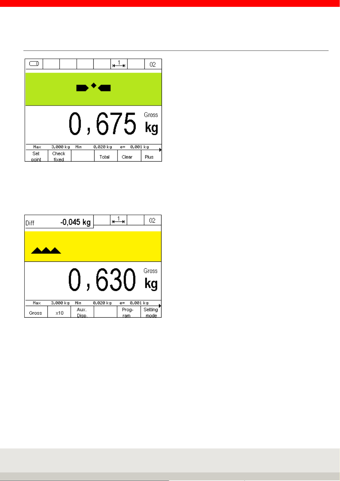
100
6.8.2 Display view
Hint: For an additional display, e.g. of the setpoint or the difference to the setpoint, you can activate an
additional auxiliary display by pressing the F3 key. The value to be displayed in the auxiliary display is set in
setting mode under Setting mode / Terminal / Display / Auxiliary display.
Illustration auxiliary display with difference to setpoint value
 Loading...