

Snap-on Verus User Manual

User Manual
August 2011
EAZ0061B46B Rev. A

Trademarks
IMPORTANT:
Snap-on, Fast-Track, Scanner, ShopStream, and VERUS are trademarks of Snap-on Incorporate d.
All other marks are trademarks or registered tr ademarks of th eir resp ective hold ers.
Copyright Information
©2011 Snap-on Incorporated. All rights reserve d.
Disclaimer of Warranties and Limitation of Liabilities
The information, specifications and illustrations in this manual are based on the latest information available at the
time of printing. While the authors have taken due care in the p rep ara tion of this manua l, nothing con t ained he rein:
• Modifies or alters in any way the standard terms and cond itions of the purchase, lea se, or rent al agre ement
under the terms of which the equipment to which this m anual relate s was acquired.
• Increases in any way the liability to the customer or to third parties.
Snap-on reserves the right to make changes at any time without notice.
Before operating or maintaining this u nit, please read this ma nual carefully paying extra attention to the safety
warnings and precautions.
Visit our websites at:
http://diagnostics.snapon.com (North America)
www1.snapon.com/diagnostics/uk (United Kingdom)
snapontools.com.au (Australia and New Zealand)
For Technical Assistance Call
1-800-424-7226 (North America)
CALL +44 (0) 845 601 4736 (United Kingdom)
1800 810 581 (Australia and New Zeal and)
E-mail DiagnosticsUKproductsupport@snapon.com (United King dom)
For technical assistance in all other markets, cont act your selling agent.
ii

Safety Information
!
DANGER
!
WARNING
!
CAUTION
For your own safety and the safety of others, and to prevent damage to the equipment an d
vehicles upon which it is used, it is important that the accompanying Important Safety Instructions
be read and understood by all persons operating, or coming into contact with, the equipment. We
suggest you store a copy near the unit in sight of the operator.
This product is intended for use by properly trained and ski lled pro fessional automo tive
technicians. The safety messages presented throughout this manual are reminders to the
operator to exercise extreme care when using this test instrument.
There are many variations in procedures, techniques, tools, and p art s for servicing vehicles, as
well as in the skill of the individual doing the work. Because of the vast number of test applications
and variations in the products that can be tested with this instrument, we cannot possibly
anticipate or provide advice or safety messages to cover every situation. It is the automotive
technician’s responsibility to be knowledgeable of the system being tested. It is essential to use
proper service methods and test procedures. It is import ant to perform tests in an appropriate and
acceptable manner that does not endanger your sa fety, the safety of others in the wor k area, the
equipment being used, or the vehicle being tested.
It is assumed that the operator has a thorough underst anding of vehicle systems before using this
product. Understanding of these system principl es and oper ating theor ies is nece ssary for
competent, safe and accurate use of this instrument.
Before using the equipment, always refer to and follow the safety messages and app licable te st
procedures provided by the manufacturer of the vehicle or equipment being tested. Use the
equipment only as described in this manual.
Read, understand and follow all safety messag es and instructio ns in this manual, the
accompanying safety manual, and on the test equi pment.
Safety Message Conventions
Safety messages are provided to help prevent personal injury and equipm ent damage. All safety
messages are introduced by a signal word indicating the haza rd level.
Indicates an imminently hazardous situation which, if not avoided, will result in death or serious
injury to the operator or to bystanders.
Indicates a potentially hazardous situation which, if n ot avoided, could result in death o r serious
injury to the operator or to bystanders.
Indicates a potentially hazardous situation which, if not a voided, may r esult in modera te or mino r
injury to the operator or to bystanders.
iii

Safety Information Important Safety Instructio ns
!
WARNING
Safety messages contain three different type styles.
• Normal type states the hazard.
• Bold type states how to avoid the hazard.
• Italic type states the possible consequences of not avoid ing th e hazard.
An icon, when present, gives a graphical description of the potential hazard.
Example:
Risk of unexpected vehicle movement.
• Block drive wheels before performing a test with the engine running.
A moving vehicle can cause injury.
Important Safety Instructions
For a complete list of safety messages, refer to the accompanying safety information.
SAVE THESE INSTRUCTIONS
iv

Contents
Safety Information..................................................................................................................... iii
Contents...................................................................................................................................... v
Chapter 1: Using This Manual................................................................................................... 1
Conventions.................................................................................................................................. 1
Bold Text................................................................................................................................ 1
Symbols ................................................................................................................................. 1
Terminology ........................................................................................................................... 1
Notes and Important Messages............................................................................................. 2
Procedures............................................................................................................................. 2
Tool Help................................................................................................................................ 2
Chapter 2: Introduction.............................................................................................................. 3
EEMS325 Display Device............................................................................................................. 3
Functional Description .. .... ... ... ... ... ....................................... ... .... ... ... ... .... .............................. 3
Technical Specifications ........................................................................................................5
The Stand .............................................................................................................................. 7
Wrist Strap (Optional)............................................................................................................. 7
Control Buttons ...................................................................................................................... 7
LEDs ...................................................................................................................................... 8
Power Conservation............................................................................................................... 8
Power Sources....................................................................................................................... 8
SCAN Module............................................................................................................................. 10
Functional Description .. .... ... ... ... ... ....................................... ... .... ... ... ... .... ............................ 10
Technical Specifications ...................................................................................................... 11
Power Sources..................................................................................................................... 11
Chapter 3: Getting Started....................................................................................................... 12
Powering Up............................................................................................................................... 12
Module Buttons.................................................................................................................... 13
VERUS Toolbar ...................................................................................................................14
Windows Toolbar .................................................................................................................19
Powering Down .......................................................................................................................... 19
Emergency Shutdown.......... ... ... ... .... ... ... ... ....................................... ... .... ... ... ... ... ................ 19
Chapter 4: Scanner Operations............................................................................................... 20
Getting Started ........................................................................................................................... 20
The Demonstration Program................................................................................................ 20
Disconnecting the VERUS Unit From a Vehicle................................................................... 21
Vehicle Identification................................................................................................................... 22
Alternative Vehicle Identification.......................................................................................... 24
Connecting to a Vehicle.............................................................................................................. 25
Cables.................................................................................................................................. 25
No Communication Message............................................................................................... 26
v

Contents
Navigation................................................................................................................................... 26
Scanner Screen Layout ....... ... ... ... .... ...................................... .... ... ... ... .... ... ......................... 26
Screen Messages ................................................................................................................ 29
Making Selections................................................................................................................ 30
Operations.................................................................................................................................. 30
Data Display......................................................................................................................... 31
Codes Menu..... .... ...................................... .... ... ... ... .... ... ...................................... .... ... ... ...... 36
Functional Tests... ... ... ... .... ... ... ... ....................................... ... ... .... ... ... ... ................................ 39
Generic Functions................................................................................................................ 41
Troubleshooter..................................................................................................................... 41
Scanner Toolbar Operations......... .... ... ... ... .... ... ....................................... ... ... ... ... .... ... ......... 42
Exiting the SCAN Module........................................................................................................... 46
Downloading Firmware...............................................................................................................47
Chapter 5: OBD Direct.............................................................................................................. 50
OBD Health Check..................................................................................................................... 50
Global OBD II Code Check..................... ... .... ... ....................................... ... ... ... ... .... ... ......... 51
Global OBD II Clear Codes........... .... ... ... ....................................... ... ... .... ... ... ... ................... 52
Readiness Monitors ............................................................................................................. 52
Connector Information .. .... ... ... ... ....................................... ... ... .... ... ... ... ................................ 53
OBD Diagnose............................................................................................................................ 53
Start Communication ........................................................................................................... 53
Select Communication Protocol........................................................................................... 57
Connector Information .. .... ... ... ... ....................................... ... ... .... ... ... ... ................................ 57
Chapter 6: Component Test .................................................................................................... 58
Vehicle Identification................................................................................................................... 58
Creating a Favorites List................... ... ... ... .... ...................................................................... 58
Identifying a Test Vehicle..................................................................................................... 60
Operations.................................................................................................................................. 62
Component Information ....................................................................................................... 62
Tests .................................................................................................................................... 63
VERUS Toolbar Menu Options............................................................................................ 67
Chapter 7: Scope Multimeter................................................................................................... 68
Getting Started ........................................................................................................................... 68
Capabilities .......................................................................................................................... 68
Leads, Probes and Adapters ............................................................................................... 70
Navigation................................................................................................................................... 73
Screen Layout...................................................................................................................... 73
Making Selections................................................................................................................ 76
Operations.................................................................................................................................. 77
Starting the Scope and Multimeter....................................................................................... 77
Scope and Multimeter Setup................................................................................................ 79
Chapter 8: Information............................................................................................................. 92
North America............................................................................................................................. 92
United Kingdom and Australia....................................................................................................92
Vehicle Identification............................................................................................................ 92
Diagnostic Trouble Codes.... ....................................... ... ... ... ... .... ... ...................................... 94
Engine Management Component Testing............................................ .... ... ... ... ... .... ...... ... ... 95
vi

Contents
Engine Management Pin Data............................................................................................. 99
Component Locations........................................................................................................ 100
Wiring Diagrams................................................................................................................. 102
Chapter 9: Help Operations................................................................................................... 104
Using the Help Toolbar.................................. ....................................... ... ... .... ... ... ... ................. 104
Chapter 10: System Settings Operations............................................................................. 105
Wireless Communication..................... ....................................... ... .... ... ... ... .... .......................... 105
Pairing the Wireless SCAN Module ................................................................................... 106
Chapter 11: Data Manager ..................................................................................................... 108
Screen Layout .......................................................................................................................... 108
My Data.............................................................................................................................. 109
Open .................................................................................................................................. 109
New.................................................................................................................................... 110
Delete................................................................................................................................. 111
Rename ............................................................................................................................. 112
Properties........................................................................................................................... 112
More................................................................................................................................... 112
Chapter 12: Vehicle History Operations............................................................................... 113
Screen Layout .......................................................................................................................... 113
Vehicle History Main Body................................................................................................. 114
Vehicle History Toolbar...................................................................................................... 114
Shop Information...................................................................................................................... 118
Chapter 13: Maintenance....................................................................................................... 119
Cleaning the Touch Screen...................................................................................................... 119
Calibrating the Touch Screen................................................................................................... 119
Cleaning and Inspecting the Unit.............................................................................................. 120
Fan Filter Service ..................................................................................................................... 120
Battery Pack Service................................................................................................................ 121
Battery Pack Safety Guidelines ......................................................................................... 121
Replacing the Battery Pack.................................. ... .... ... ... ... ... ....................................... ... . 122
Disposing of the Battery Pack....... .... ... ... ... .... ...................................... .... ... ... ... ... .............. 122
Battery Pack Calibration .................................................................................................... 123
VERUS System Restore........................................................................................................... 123
Wireless SCAN Module.................................... .... ... ... ... .... ... ...................................... .... ... ... .... 124
Replacing the Protective Handgrip.......................................... .... ... ... ... .... ... ...... ... .... ... ... ... . 124
Appendix A: Accessories...................................................................................................... 125
Index........................................................................................................................................ 126
vii

Chapter 1 Using This Manual
This manual contains instructions for using the VERUS® Diagnostic Plat form .
Some of the illustrations shown may include optional equipment that is not on your system.
Contact a sales representative for availability of accessories and optional equipment.
1.1 Conventions
1.1.1 Bold Text
Bold emphasis is used in procedures to highlight select able items such as butto ns and menu
options.
Example:
• Select Functions.
1.1.2 Symbols
The “greater than” arrow (>) indicates an abbreviated set o f se lection instructions.
Example:
• Select Utilities > T ool Setup > Date.
The above statement abbreviates the following procedu re:
1. Select the Utilities button.
2. Select the Tool Setup submenu.
3. Highlight the Date option from the submenu.
1.1.3 Terminology
The term “select” means highlighting a button or menu item usi ng the stylus.
Example:
• Select Reset.
The above statement abbreviates the following procedu re:
1. Navigate to the Reset button.
2. Press the Reset button with your stylus.
1

Using This Manual Conventions
NOTE:
IMPORTANT:
1.1.4 Notes and Important Messages
The following messages are used.
Note
A note provides helpful information such as additional explanations, tip s, and comments.
Example:
i For additional information refer to...
Important
Important indicates a situation which, if not avoided, may result in damage to the test equipment
or vehicle.
Example:
Disconnecting the USB cable during vehicle communication can cause damage to the PCM.
1.1.5 Procedures
An arrow icon indicates a procedure.
Example:
z To change screen views:
1. Select View.
The dropdown menu displays.
2. Select an option from the menu.
The screen layout changes to the format you selected.
1.1.6 Tool Help
To display help topics for this tool, select a help op tion from the He lp menu.
2

Chapter 2 Introduction
The VERUS® Diagnostic Platform is a specialized personal compu ter (PC) that combines
information with test instrumentation to help you diagno se symptoms, co des, and complain t s
quickly and efficiently , test vehicle systems and components, access service records and
recorded data, and verify repairs. VERUS fo rms a complete automotive diagnostic solution. There
are two main components to the VERUS Diagnostic plat form:
• EEMS325 Display Device—the central processor and system monitor with integral scope.
• SCAN Module—the device for accessing vehicle data.
Microsoft Windows Embedded is the operating system of the base unit, which allows VERUS to
run most Windows compatible software programs. The st andard Windows toolba r displays at the
bottom of the screen. Unique Snap-on software that allows VERUS to function as a scan tool,
graphing multimeter, lab scope, and a powerful diagnostic database opens on st artup .
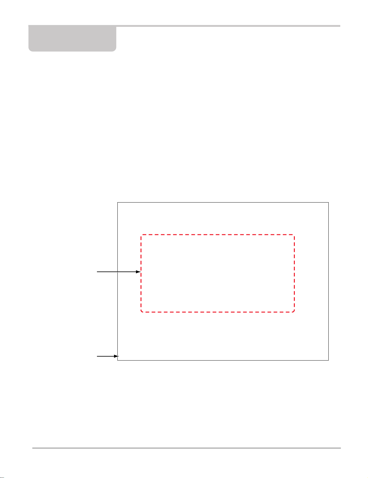
2.1 EEMS325 Display Device
2.1.1 Functional Description
1— Audio Speaker
2— Touch Scre en Display
3— Microphone
4— S Button
5— Virtual Keyboard Button
6— Brightness Up Button
7— Brightness Down Button
8— Hard Drive Activity LED
9— Wireless LAN Activity LED
10—Battery Charging LED
11—Main Power LED
12—Power Button
Figure 2-1 Front view
3

Introduction EEMS325 Display Device
IMPORTANT:
There are two versions of the VERUS Display Device: the standard unit with in tegral Scanner that
connects to the vehicle with a data cable, and the wirele ss unit that uses the stand-alone SCAN
Module and does require a physical link to the test vehicle. The to p view of the two mode ls are
distinctly different, as shown in the illustrations below. Earlier standard unit s can be converted to
operate with the wireless Scan Module, contact your sales represent ative for det ails.
1— VGA (video graphics array) Port
2— LAN (local area network) Port
3— USB (universal serial bus) Ports (2)
4— Audio (head phone) Port
5— DC Power Supply Input Port
6— Fan Filter
7— Scope Auxiliary Port
8— Channel 4 Port
9— Channel 3 Port
10—Channel 2 Port
11—Channe l 1 Port
12—Common Ground Port
Figure 2-2 T op view, wireless model
4
Introduction EEMS325 Display Device
1— VGA (video graphics array) Port
2— LAN (local area network) Port
3— USB (universal serial bus) Port
4— Audio (head phone) Port
5— DC Power Supply Input Port
6— Fan Filter
7— Data Cable Port
8— Scope Auxiliary Port
9— Channel 4 Port
10—Channel 3 Port
11—Channe l 2 Port
12—Channel 1 Port
13—Common Ground Port
Figure 2-3 Top view, standard model
2.1.2 Technical Specifications
Processor:
1.6GHz Intel Atom
Memory:
1GB RAM
Operating System
Microsoft Windows Embedded Standard (XPe SP3)
5

Introduction EEMS325 Display Device
T ouc h Screen
5-wire Resistive Touch Panel
Display:
10.4 inch, outdoor enhanced, TFT LCD
1024 x 768 resolution
262,144 Colors
Battery:
Lithium Ion Smart Battery Pack
Approximately 4 hour run time
Approximately 4 hour charge time, VERUS not operating
Approximately 8 hour charge time, VERUS operating
Communications:
10/100 Ethernet Port
802.11 b/g Wireless LAN
Bluetooth 2.0 Class 1
Dimensions:
Width:
14.9 inches
358 mm
Height:
9.17 inches
233 mm
Depth:
3.07 inches
78 mm
Weight (including battery):
7.5 lbs.
3402 g
Operating Temperature Range (ambient):
At 0 to 90% relative humidity (non-condensing)
32 to 113°F
0 to 45°C
Storage Temperature (ambient):
At 0 to 70% relative humidity (non-condensing)
–4 to 131°F
–20 to 55°C
Environmental Conditions:
This product is intended for indoor use only
This product is rated for Pollution Degree 2 (normal conditions)
6
Introduction EEMS325 Display Device
Power Supply:
Supply Rating; 12–17 VDC. 3.53A
Output; 17VDC 60W, LPS (limited power source)
2.1.3 The St and
The VERUS unit has a built-in, metal stand attached to the back. When the stand is not in use, it
is secured to the back of the unit by an integrated casing hook. When exte nded, the st and allows
the unit to rest at a 45° angle for hands-free viewing.
2.1.4 Wrist Strap (Optional)
An adjustable wrist strap that attaches to the back of the unit to secure and stabilize the VERUS
while you work is available as an option. Using the wrist strap allows the VERUS to comfortably
rest on your forearm and leaves a hand free for connecting test leads and operating the touch
screen. The strap also eliminates the possibility of the VERUS falling off a vehicle due to vibrations
or other movement, and also prevents you from accident ally drop ping the too l.
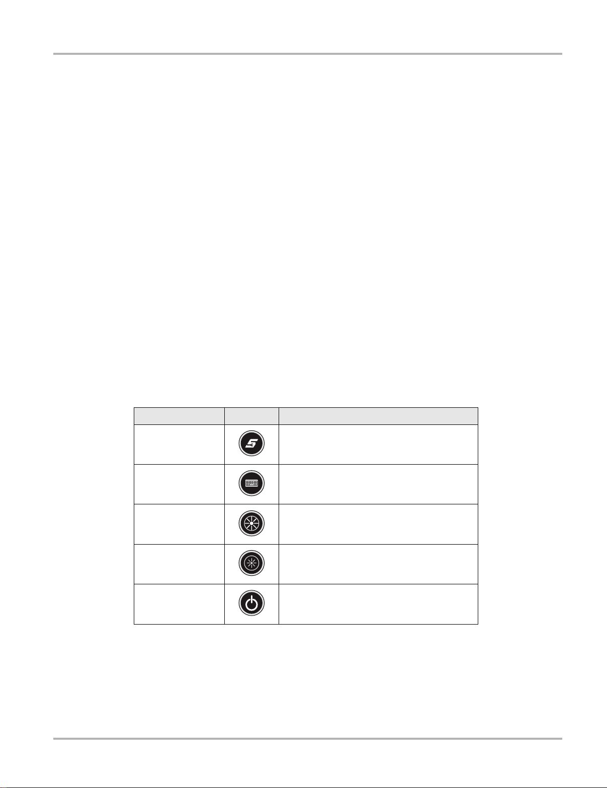
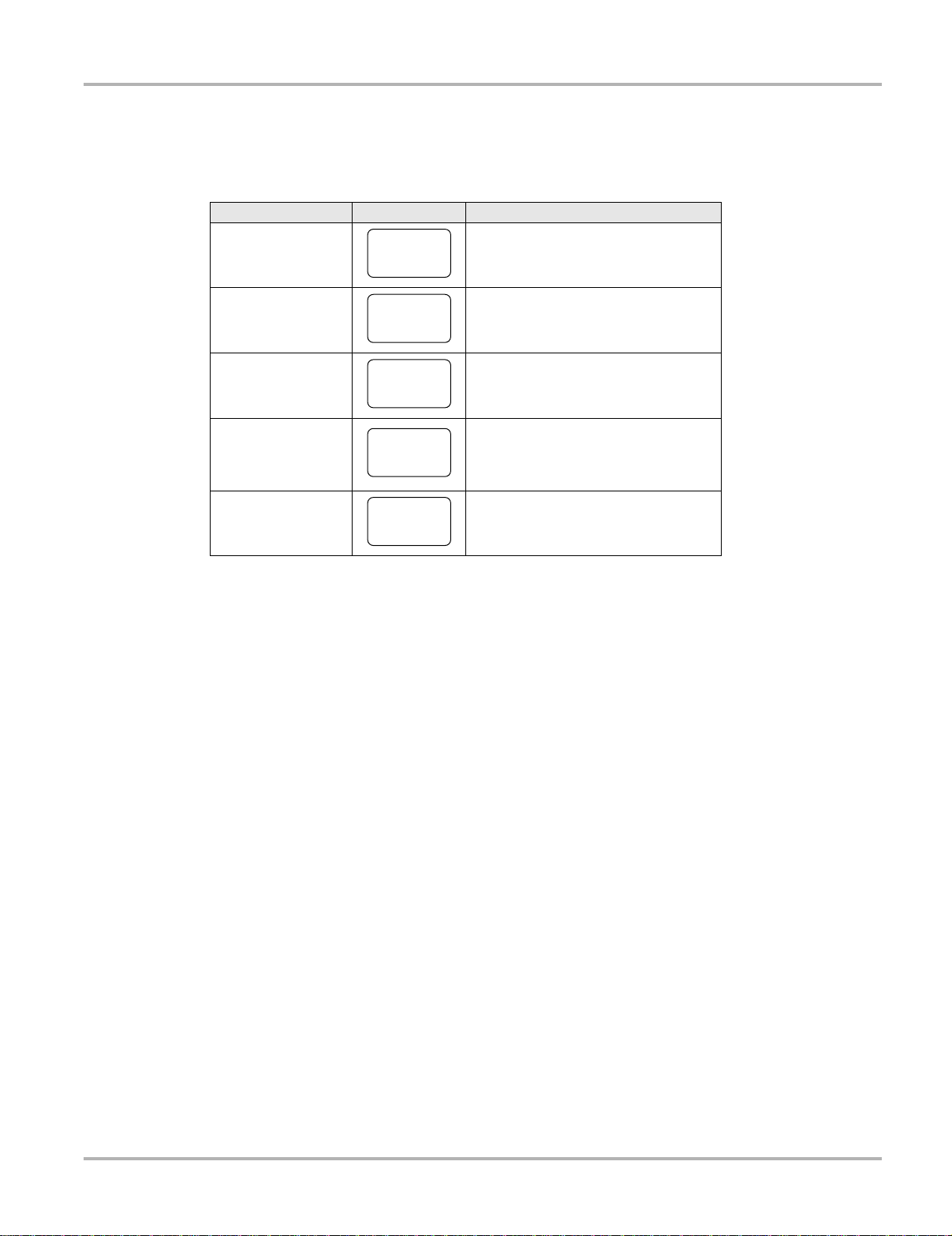
2.1.5 Control Buttons
There are five control buttons located on the right side of the un it near the han dgrip:
Name Button Description
S Button
Keyboard
Brightness Up
Brightness Down
Power
All other tool operations are controlled through the touch screen.
A function button that provides a shortcut for
performing routine tasks.
Opens, and closes, a virtual keyboard on the
touch screen.
Incrementally increases the screen
backlighting.
Incrementally decreases the screen
backlighting.
Turns the unit on and off. Also, press and hold
for 5 seconds for emergency shutdown.
7

Introduction EEMS325 Display Device
NOTE:
S Button
Use the S Button to quickly capture an image of the current screen with a single button press. This
screen capture function is available at all times, even when operating out s ide of the VERUS
Diagnostic Platform software.
2.1.6 LEDs
The four light-emitting diodes indicate certain system conditions:
• Hard Drive Activity LED—illuminates when the central processing unit (CPU) is reading or
writing to the hard disk drive (HDD).
• Wireless LAN Activity LED—illuminates when a wireless local area network (LAN) in enabled,
flashes when data is being sent or received.
• Battery Charging LED—illuminates when the internal battery pack is charging.
• Main Power LED—illuminates when the unit is powered on or in Standby mode.
2.1.7 Power Conservation
To conserve power, the VERUS unit uses a power saving strategy when left idle. Standby mode
engages following a period of inactivity. During standby, the random access memory (RAM)
remains powered, but all other functions are turned off. The screen shuts o ff and the Main Power
LED remains illuminated when in standby mode.
i The Standby mode char acteristics can be configur ed by selecting Po wer Opt ions from the
Windows Control Panel menu.
2.1.8 Power Sources
Your VERUS unit can receive power from any of the follo wing sou rces:
• Internal Battery Pack
• Charging Station (Optional)
• AC/DC Power Supply
• Data Link Connector (DLC), Standard Unit Only
Internal Battery Pack
The VERUS unit can be powered from a rechargeable lithium ion battery located on the bottom of
the unit under the right handgrip (Figure 2-5). A fully charged battery provides sufficient power for
about four hours of constant operation.
8
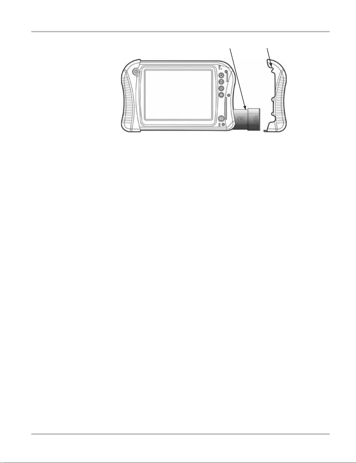
Introduction EEMS325 Display Device
1— Internal Battery Pack
2— Right Handgrip
Figure 2-4 Battery pack location
The battery is recharged on demand whenever the un it is pl aced in the optional do cking st ation,
or the AC/DC power supply is connected to a voltage source.
Charging Station (Optional)
The unit can be powered and operated wh en installed on the optional charging station. The
charging station also powers the internal battery p ack charging proce ss and allows USB
connectivity for attaching peripherals. Contact your sale represent a tive for addition al det ails.
AC/DC Power Supply
The unit can be powered from a wall socket using the AC/DC power supply an d power cord. T he
AC/DC power supply also powers the internal battery pack charging process.
Data Link Connector (DLC), Standard Unit Only
The standard VERUS unit can be powered through the DLC when connecte d to an OBD-II vehicle
with the data cable. However, battery pack charging is not available when the unit is being
powered by the DLC.
9
Introduction SCAN Module
2.2 SCAN Module
The wireless SCAN Module is provided as standard eq uipment on all late-mo del VERUS un it s.
Older VERUS units, which are designed to operate with a h ard-wired con nection to the test
vehicle, can also be converted to operate with the wireless SCAN Module.
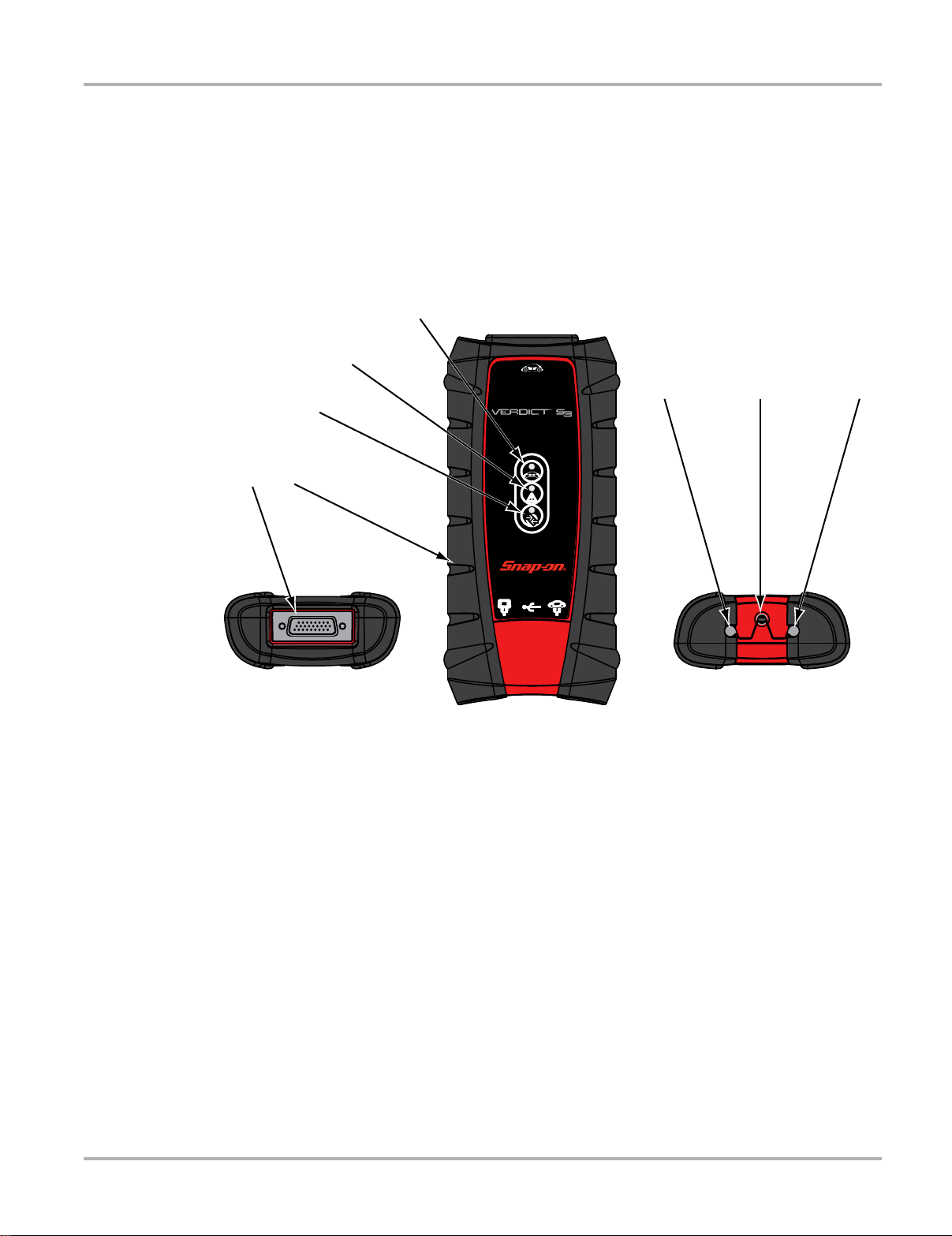
2.2.1 Functional Description
7RS
)URQW
%RWWRP
1— Data cable connector
2— Memory card port (remove protective hand grip for access)
3— Bluetooth LED (green)
4— Communication issue LED (red)
5— Vehicle power LED (green)
6— Ethernet port (remove protective hand grip for access)
7— Universal serial bus (USB) port (remove protective hand grip for access)
8— Ethernet port (remove protective hand grip for access)
Figure 2-5 SCAN Module
Wireless Communication
The SCAN Module is a wireless communications device that transmit s vehicle data to the VERUS
display device without a physical connection. The working range of the transmitter is about 30 feet
(9.14 m). A signal lost due to moving out of range automatically restores it self wh en th e display
unit is brought closer to the SCAN Module. The SCAN Module sounds a tone and the Display
Device shows a warning message when the signal is lost.
10

Introduction SCAN Module
2.2.2 Technical Specifications
Communications:
Bluetooth 2.0 Class 1
Dimensions:
Length:
8.04 inches
204.3 mm
Height:
3.82 inches
97 mm
Depth:
1.66 inches
42.1 mm
Weight (including protective hand grip):
0.9 lbs.
0.408 kg
Operating Temperature Range (ambient):
At 0 to 90% relative humidity (non-condensing)
32 to 113°F
0 to 45°C
Storage Temperature (ambient):
At 0 to 70% relative humidity (non-condensing)
–4 to 140°F
–20 to 60°C
Environmental Conditions:
This product is intended for indoor use only
This product is rated for Pollution Degree 2 (normal conditions)
2.2.3 Power Sources
The SCAN Module operates on 12-volt vehicle power, which it receives through the dat a cab le
connector. The unit powers o n whenever it i s connected to an OBD-II complia nt dat a link
connector (DLC). For non OBD-II compliant vehicles, the unit can be powere d from a cigare tte
lighter or other suitable power port on the test vehicle using the optional auxiliary power cable.
11
Chapter 3 Getting Started
Make sure the VERUS® Diagnostic Platform has a charged batte ry or is conn ected to a n
AC power supply (see “Power Sources” on page 8). It is recommended that you calibrate the
touch screen on you VERUS unit on initial startup, and as need while the unit is in ser vice (see
“Calibrating the T ouch Screen” on page 119).
It is highly recommended to back up personal and saved dat a to a USB mass storage de vice on
a regular basis to prevent loss in the event of system corruption or hard disk drive failure.
3.1 Powering Up
Press the Power button to switch the unit on. The system boot s up, the n opens the VERUS
Diagnostic Platform to the Home screen (Figure 3-1).
1— Module Buttons
2— VERUS Toolbar
Figure 3-1 Sample VERUS Home screen
12

Getting Started Powering Up
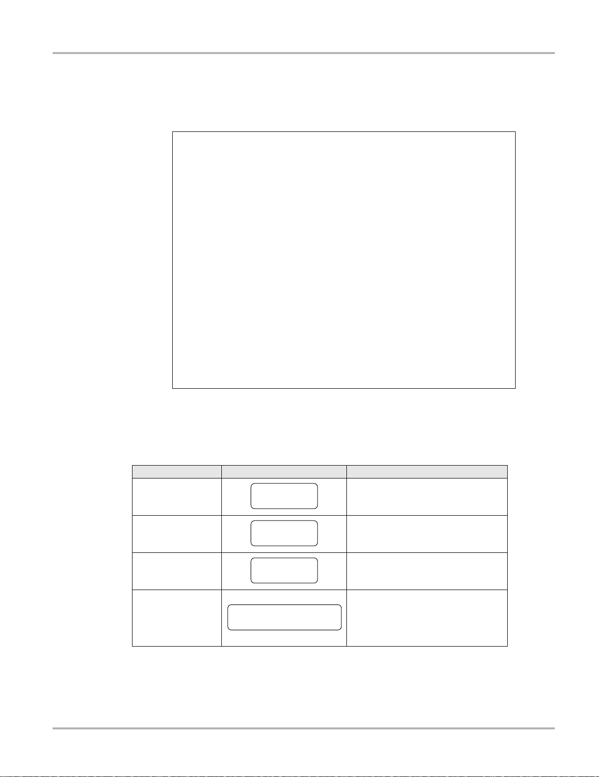
3.1.1 Module Buttons
The Module buttons configure the VERUS unit for the type of te st to be perfor med. The t able
below gives brief descriptions of the function of each button:
Table 3-1 Module toolbar buttons
Name Button Description
Configures the VERUS unit to operate
Scanner
OBD Direct
Component Test
Scope Multimeter
as a scan tool. See
Operations” on page 20
Allows you to perform generic OBD-II
system tests without identifying the
specific vehicle.
Opens a diagnostic database of
specific tests for the identified vehicle.
See “Component Test” on page 58.
Configures the VERUS unit to operate
as a lab scope, graphing multimeter, or
digital multimeter. See “Scope
Multimeter” on page 68.
“Scanner
.
Provides the information needed to
make repairs once you have made
Information
Help Opens the on-line help for the system.
Data Manager
Vehicle History
System Settings
Exit
your diagnosis. The linked program
varies by region. See “Information” on
page 92.
Opens the organization system for
saved data files. See “Data Manager”
on page 108.
Opens a list of previously serviced
vehicles.
Establishes and manages wireless
communication between modules.
Closes the VERUS Diagnostic Suite
application.
Use your finger or the stylus to tap the desired module and open that app lication.
13
Getting Started Powering Up
3.1.2 VERUS Toolbar
Operation of the toolbar buttons located on the lower-left area of the screen are described below:
Table 3-2 Module buttons
Name Button Description
Home
Windows Toolbar
Menu
Change Vehicle
View Record
Touching this button returns you to the
VERUS Home screen from any test.
Touching this button opens and closes
the standard Windows toolbars at the
bottom of the screen.
Touching this button opens a menu of
common operations and information.
The currently identified vehicle is
shown to the right of the buttons,
touching allows you to change the
identified test vehicle.
Touching the button opens an editable
worksheet of vehicle records.
Menu Button Options
The Menu button on the VERUS Toolbar at the base of the display screen opens a list of basic
operations and features. Menu options vary by mo dule an d may include :
• Safety Information—opens the Important Safety Instructions document, which should be
read and understood prior to using the VERUS Diagnostic Plat fo rm.
• File—allows you to print or save the data being viewed.
• View—allows you to change the size of the screen text.
• Tools—allows you to perform certain maintenance operation s and adju st tool se ttings.
• Help—allows you to view supporting documentation.
Selecting a menu item opens a submenu of choices, and some submenus also open a n additional
menu. A right arrowhead (c) indicates addi tional choices are available. Touch an item to select it.
File
Use to print or save a copy of the data currently being viewed. Selecting opens a submenu:
• Save—available from the SCAN Module, opens an additional submenu with these options:
– Screenshot—saves a graphic image of the current screen
– Collected Data—saves a recording of all the data currently in the buf fer plus the number
of frames designated after the trigger event (see “Properties” on page 44).
• Print—available from the SCAN Module, opens an additional submenu with these op tions:
– Screen—sends the current screen image to a printer.
– Troubleshooter—prints the full text of the troubleshooter topic shown in the main body.
14

Getting Started Powering Up
• Print Article—available from the Component Test module, has one of the following results:
– If VERUS is connected to a printer, the file is sent to the printer.
– If VERUS is not connected to a printer, the article is saved as a .xps file, which can be
retrieved, moved, or copied and printed at a later time.
Selecting a print option opens a standard Windows Prin t dialog bo x, which allows yo u to print or
save the file.
Tools
This SCAN Module option allows you to adjust tool settings to your personal prefer ences.
Selecting Tools opens a subm enu of the follo wing sections.
Units Setup
Selecting opens a dialog box that allows you to choose between US customary or metric units of
measure for temperature, vehicle speed, air pressure an d other pre ssure reading s.
Figure 3-2 Sample view options
Table 3-3 Scan tool units of measurement, defaults and options
Setting Default Option
Temperature degrees Celsius (°C) degrees Fahrenheit (°F)
Air Pressure
(including manifold pressure)
Vehicle Speed kilometers per hour (KPH) miles per hour (MPH)
Other Pressure kilopascal (kPa) pounds per square inch (PSI)
kilopascal (kPa) inches of mercury (“Hg)
z To change the units setup:
1. From the VERUS toolbar select Tools > Units Setup.
The Measurement Units Setup dialog box opens.
2. Use the dropdown menus to select the desired value for each ite m.
3. Tap Accept to close the dialog box and a pply the ch anges.
15

Getting Started Powering Up
NOTE:
NOTE:
i All measurement units return to their default values when different sof twa re is selecte d.
Download Firmware
This option is used to update the firmware on your VERUS unit. For firmware information, contact
your sales representative or Customer Care. While downloading the firmware, do not interrupt the
download process. Connection interruption may cause damage to the SCAN Module.
i It is recommended to connect the VERUS to an AC power source when downloading firmware.
Display BEN
This option shows the Balco Engine Number (BEN) of the currently ide ntified vehicle in the
Scanner toolbar , which is used inte rnally fo r dat a coordina tion.
Help
A variety of utilities and additional resources are available through the Help menu. Menu options
vary by module and may include:
• User Manual
• Vers ion Info
• Activation Status
• User’s Manuals
• About Component Test
• About Scanner
• Shop Information
User Manual
This option opens this document, which provides overall navigation and oper ation information for
the VERUS Diagnostic Platform.
Version Info
This option opens a window showing the version of the VERUS software and the Sof twa re
License Agreement (Figure 3-3). Tap OK to close the window.
16

Getting Started Powering Up
Figure 3-3 Sample software version screen
Activation Status
This option opens a dialog box with version and lice nsing det a ils for the VERUS system, and
activation status for all of the modules.
User’s Manuals
This SCAN Module option opens a submenu of support document ation, such as vehicle
communication software manuals. These manu als provide co nnection an d test inform ation for
specific vehicles. Selecting a menu item opens a printable PDF ve rsion of the docume nt in a
separate window .
About Component Test
This option opens a dialog box that contain s so f tware vers ion and details, copyright data, and
other specific details about the Component Test module.
About Scanner
This option opens a dialog box that contain s so f tware vers ion and details, copyright data, and
other specific details about the SCAN Module.
Shop Information
This Vehicle History o ption that allows you to add personalized shop information that can be
included on printed data files. Selecting opens a form that can be filled in using the virtual
keyboard. Select OK when done and the information is saved.
17
Getting Started Powering Up
View Record
The year make and model of vehicle currently identified is shown on the too lba r. Touching the
button opens the worksheet, or service record, of the test vehicle (Figure 3-4).
Figure 3-4 Sample vehicle worksheet
Use the virtual keyboard to enter data in the worksheet and select Back when finished. A toolbar
at the top of the screen controls worksheet o peratio ns as explained in the t abl e below:
Table 3-4 Worksheet toolbar buttons
Name Button Description
Back
Delete
Print
Change Vehicle
Touching this button returns you to the
previously viewed screen.
Touching this button removes the
vehicle record displayed on the screen.
from the vehicle history list.
Touching this button sends the
worksheet to a printer.
Touching the button saves any
changes made to the worksheet and
closes it. This also terminates Scanner
communication with the vehicle if the
Scanner is active.
18

Getting Started Powering Down
3.1.3 Windows Toolbar
This is the standard Windows toolbar. Y our VERUS unit is a fully functional personal computer
based on the Windows Embedded S t andard ope rating system. Refer to Microsoft documenta tion
for additional information.
3.2 Powering Down
All vehicle communication must be terminated before shutting down the VERUS unit. Failure to do
so may lead to ECM problems on some vehicles. Always exit the SCAN Module before powering
down the VERUS unit.
z To power down the VERUS unit:
1. Open the Windows S t a rt menu.
2. Select Turn Off Computer.
3. Select Turn Off in the dialog box.
The open programs close and the power switches of f.
3.2.1 Emergency Shutdown
In case of emergency, press and hold the Power button to force a shut down.
19

Chapter 4 Scanner Operations
On early-model VERUS units the Scanner is built into the display device. On later-model units the
SCAN Module is a stand-alone unit that communicates wirelessly with the VERUS Display
Device. Operation and function are similar for both the integr al Scanner and the wireless SCAN
Module. The information in this chapter applies to both, unless otherwise specified.
The SCAN Module allows you to establish a data link to the electronic control systems of the
vehicle being serviced to retrieve diagnostic trouble codes (DTCs) view live data p arameters, and
perform tests. The SCAN Module can access the electron ic control modu le (ECM ) for vario us
vehicle control systems such as engine, transmission, antilock brake system (ABS) and more.
Testing requires connecting the SCAN Module to th e test vehicle u sing the dat a cable and test
adapters. The SCAN Module communicates wirelessly with the VERUS Diagnostic Platfor m.
Instructions on the VERUS screen tell you how to connect the SCAN Module. Additional
connection information can be found in the appropriate vehicle communication sof tware manual
for the test vehicle, which is available through the Help menu.
4.1 Getting St arted
Prior to its first use, a wireless SCAN Module must be synchronized with the VERUS Display
Device to establish a communication link. Refer to “Pairing the Wir eless SCAN Modu le“ on
page 106 for instructions and additional information.
The following steps get you started communica ting with a ve hicle:
1. Tap the Scanner ico n on the Ho me screen to laun ch th e Scanner sof t ware
2. Follow the screen instructions to identify the test vehicle
3. Connect the VERUS unit to the test vehicle with the data cable
4. Navigate through the Scanner menus to begin testing
A demonstration program allows you to become familiar with SCAN Module operations and
testing without being connected to an actual vehicle.
4.1.1 The Demonstration Program
The SCAN Module demonstration program allows you to become familiar with many of the test
capabilities without connecting to a vehicle. Sample data and mock test results help you learn the
menus and basic operations.
When applicable, both the SCAN Module and the display device must be powered on .
z To start the demonstration program:
1. From the VERUS Home screen, tap the Scanner icon.
20

Scanner Operations Getting Started
IMPORTANT:
The manufacturer menu displays. This menu lists includes all makes that are covered by any
of the VERUS modules, not just those for which information is available. There is a
Demonstration button that launches the program is also included in the list.
2. Tap the Demonstration button.
Figure 4-1 Sample demonstration selection
A screen with two choices now displays:
– US Domestic—contains actual data captu red while driving a 2001 C hevrolet Tahoe. Look
for the throttle position (TP) sensor dropout while analyzing the data in Graphing mode.
– OBD Training Mode—provides simulated data for an OBD-II/EOBD vehicle that allows
you to access any of the standard functions.
3. Select either option and a confirmation messa ge disp lays.
4. Select Ok to load the selected database.
5. Follow the on-screen instructions and select as needed until the Systems menu displays.
6. Select from any of the systems listed, then select from the submenus.
Do not connect a vehicle to the VERUS unit while in the Demonstration mode.
4.1.2 Disconnecting the VERUS Unit From a Vehicle
When disconnecting the VERUS unit from the vehicle, make sure the SCAN Module software is
not communicating with the vehicle.
21

Scanner Operations Vehicle Identification
NOTE:
z To exit the SCAN Module and disconnect the VERUS Unit from a vehicle:
1. From a codes or data display screen, t ap th e Exit button on the upper toolb ar.
Figure 4-2 Sample upper toolbar Exit button
The screen goes to the codes or data menu.
2. Tap the Back button on the upper toolbar.
Figure 4-3 Sample upper toolbar Back button
The screen goes to the system menu.
3. Tap the Back button on the upper toolbar.
A “stopping communication” briefly displays followed by the systems menu.
4. Tap the Change Ve hicle button on th e VERUS toolba r.
Figure 4-4 Sample VERUS toolbar Change Vehicle button
The vehicle description on the toolbar should now read “No Active Vehicle”.
5. Tap the Home button on the VERUS toolbar.
Figure 4-5 Sample VERUS toolbar Home button
The Home screen displays.
6. Disconnect the test adapter from the vehicle connector.
i Damage to the electronic control module (ECM) of the vehicle can occur if communica tion is
disrupted. Ensure that the vehicle communication cable is pr operly connected a t all times during
testing. Exit testing before removing the test cable or powering down.
4.2 V ehicle Identification
The SCAN Module information presented is provided by a direct link to the ECM of the vehicle
being tested. Therefore, certa in attributes of the test vehicle must be entered into the VERUS unit
so that the data displays correctly. V ehicle identification information is carried over if you enter the
SCAN Module either from the Component Test module or from one of the records stored in the
Vehicle History mod ule. However, you may need to enter additional attributes in some inst an ces.
22

Scanner Operations Vehicle Identification
NOTE:
The vehicle identification sequence is menu driven, you simply follo w the scree n prompts and
make a series of choices. Each selection you make advances you to the next screen. A Back
button in the upper left corner of the screen returns you to the previous screen. Exact procedures
may vary somewhat by vehicle.
z To identify a vehicle for SCAN Module testing:
1. Tap the Scanner module button from the Home screen.
A list of manufactures displays (Figure 4-6).
Figure 4-6 Sample manufacturer list
2. Select the manufacturer of the test vehicle from the list.
A model year menu displays.
i You can limit the number of manufacturers that appear on the list by selecting Configure Favorites
from the toolbar. See “Creating a Favorites List“ on page 58 for details.
3. Select the year of the test vehicle from the menu.
A list of vehicle types or models displays. Several selections may be required to identify the
vehicle type and model, follow the screen prompt s and enter the required information.
A confirmation dialog box displays once all the required dat a has been en tered.
4. From the Confirm vehicle details dialo g box, select:
a. OK to continue.
b. Cancel to return to the engine list.
When Yes is selected list of systems available for testing on the identified vehicle displays.
5. Select a test to continue (Figure 4-7).
23
 Loading...