

Snap-On Versus Edge User Manual

User Manual
ZEEMS330A Rev. B

Legal Information
IMPORTANT:
Trademarks
Snap-on, ShopS tream Connect, SureT rack, Fast-Tra ck Troubleshoote r, ProDem and, ShopKey Pro and VERUS are
trademarks registered in the United States and other countries of Snap-on Incorporated. All other marks are
trademarks or registered trademarks of their respective holders.
The Bluetooth word mark and logo s are re gistered tra demarks owned b y Bluetooth SIG, Inc. and any use of such
marks by Snap-on Incorporated is under license.
Copyright Information
© 2015 Snap-on Incorporated. All rights rese rved.
Disclaimer of Warranties and Limit ation of Liabilities
All pictures and illustrations shown are for reference purposes only. All information, specifications and illustrations in
this manual are based on the latest information available at the time of printin g and are sub ject to chan ge without
notice. While the authors have taken due care in the pr ep aration o f this m anual, no thing contained herein:
• Modifies or alters in any way the standard terms and co nd itions of the purch ase, lease, or rent al ag reement
under the terms of which the equipment to which this m anual relate s was acquired.
• Increases in any way the liability to the customer or to third parties.
Snap-on
®
reserves the right to make changes at any time without notice.
Before operating or maintaining this unit, pl ease re ad this manual car efully p aying extra atten tion to the sa fety
warnings and precautions.
Contact Information (North America)
Websites:
Snap-on Diagnostics and Information
• http://diagnostics.snapon.com
Software Subscription - Learn how to always h ave the latest di agnostic sof tware o n your Diagnostic Tool.
• http://diagnostics.snapon.com/theprogram
Training and Supp ort (by pl at form) - Find prod uct support infor mation, and watch fr ee instructiona l prod uct
videos.
• http://diagnostics.snapon.com/FAQ.htm
Manuals / T echnical Document ation - The information in this manual is peri odically revised to ensure the latest
information is included. Download the latest version of this manual and other related technical do cumentation at :
• http://diagnostics.snapon.com/usermanuals
Forums and T raining - Watch free instructional product videos. Connect with and share your Diagnostic Tool
questions, ideas and success stories :
• http://diagnostics.snapon.com/ForumsandTraining.htm
Phone / E-mail - Technical Assistance
1-800-424-7226 / diagnostics_support@snapon.co m
For technical assistance in all other markets, contact your selling agent.
ii
ZEEMS330A Rev. B 8-J-15 NA

FCC Compliance Statement
This equipment has been tested and found to comply with the limit s for a Class B digita l device, pur suant to p art 15
of the FCC rules. These limits are designed to provide rea sonable prote ction against har mful interfer ence in a
residential installation. This equipment generates, uses and can radiate radi o frequency energy and, if not inst alled
and used in accordance with the instructions, may cause harmful interferen ce to radio co mmunications. However,
there is no guarantee that interference will not occur in a particular installation. If this equipment does cause harmful
interference to radio or television reception, which can be determined by turning the equipment of f and on, the user
is encouraged to try to correct the interference by one or more of the following measur es:
• Reorient or relocate the receiving antenna.
• Increase the separation between the equipment and receiver.
• Connect the equipment into an outlet on a circuit different from that to which the receiver is connected.
• Consult the dealer or an experienced radio/TV te chnician for help .
CAUTION
You are cautioned that changes or modifications not expressly approved by the party responsible for co mpliance
could void your authority to operate the equipment.
FCC RF Radiation Exposure Statement
1. This transmitter must not be co-located or operating in conjunction with any other anten na or transmitter.
2. This equipment complies with FCC RF radiation exposure limits set forth for an uncontrolled environment. This
device was tested for typical lap held operations with the device contacted directly to the human body to the back
side of the Display Unit. T o maintain complia nce with FCC RF exposure compliance requirement s, avoid direct
contact to the transmitting antenna during transmitting.
3. According to FCC 15.407(e), the device is intended to operate in the fr equency b and of 5. 15GHz to 5.25GHz
under all conditions of normal operation. Normal operation of th is device is restricted to ind oor used on ly to
reduce any potential for harmful interference to co-c hannel MSS ope rations.
iii

***IMPORTANT INFORMATION***
Operating System (OS)
Your VERUS® Edge delivers exclusive coverage, more capabilities, superior performance and runs on a special
version of the Microsoft
DO NOT install another operating syste m on this diagnostic tool. The modification or inst allation of a different OS
or OS version will damage the diagnostic tool and void its warranty.
®
Windows® 7 operating system.
iv

Safety Information
READ ALL INSTRUCTIONS
For your own safety, the safety of others, and to prevent damage to the product and vehicles upon
which it is used, it is important that all instructions and safety messages in this manual and the
accompanying Important Safety Instr uction s ma nual be re ad and under stood by a ll person s
operating, or coming into contact with the product, before operating. W e suggest you store a copy
of each manual near the product in sight of the operato r.
For your safety , read all instructions. Use your diagnostic tools only as described in the tool user’s
manual. Use only manufacturer recommended parts and accessories with your diagnostic tools.
This product is intended for use by properly trained and skilled p rofessional a utomotive
technicians. The safety messages presented throughout this manual and the accompanying
Important Safety Ins tructions manual are reminders to the operator to exercise extreme care when
using this product.
There are many variations in procedures, techniques, tools, and p art s for servicing vehicles, as
well as in the skill of the individual doing the work. Because of the vast number of test applications
and variations in the products that can be tested with this instrument, we cannot possibly
anticipate or provide advice or safety messages to cover every situation. It is the responsibility of
the automotive technician to be knowledgeable of the system being tested. It is essential to use
proper service methods and test procedures. It is import ant to perform tests in an ap propriate and
acceptable manner that does not endanger your sa fety, the safety of others in the work area, the
equipment being used, or the vehicle being tested.
It is assumed that the operator has a thorough underst anding of vehicle systems before using this
product. Understanding of these system principl es and oper ating th eories is nece ssary fo r
competent, safe and accurate use of this instrument.
Before using the equipment, always refer to and follow the safety messages and applicable test
procedures provided by the manufacturer of the vehicle or equipment being tested. Use the
product only as described in it’s user manual. Use o nly manufacturer recom mended p arts and
accessories with your product.
Read, understand and follow all safety messag es and instru ctions in this manual , the
accompanying Important Safety Instr uction s ma nual, and on the test equipme nt.
Environmental Conditions:
• This product is intended for indoor use only
• This product is rated for Pollution Degree 2 (normal conditions)
v
Safety Information Safety Signal Words
'$1*(5
:$51 ,1 *
:$51 ,1 *
Safety Signal Words
All safety messages contain a safety signal word that indica tes th e level of th e haza rd. An ico n,
when present, gives a graphical description of the ha zard. Sa fety Signal wor ds are:
Indicates an imminently hazardous situation which, if not avoided, will result in death or serious
injury to the operator or to bystanders.
Indicates a potentially hazardous situation which, if not avoided, could result in death o r serious
injury to the operator or to bystanders.
&$87,21
Indicates a potentially hazardous situation which, if not a voided, may result in moderate or minor
injury to the operator or to bystanders.
Safety Message Conventions
Safety messages are provided to help prevent personal injury and e quipment dam age. Safe ty
messages communicate the hazard, hazard avoidance an d possible con sequences using three
different type styles:
• Normal type states the hazard.
• Bold type states how to avoid the hazard.
• Italic type states the possible consequences of not avoidi ng the ha zard.
An icon, when present, gives a graphical description of the potential hazard.
Safety Message Example
Risk of unexpected vehicle movement.
• Block drive wheels before performing a test with engine runn ing.
A moving vehicle can cause injury.
Important Safety Instructions
For a complete list of safety messages, refer to the accomp anying Import ant Safety Instructions
manual.
SAVE THESE INSTRUCTIONS
vi

Content s
Safety Information...................................................................................................................... v
Chapter 1: Using This Manual................................................................................................... 1
Conventions.................................................................................................................................. 1
Bold Text................................................................................................................................1
Symbols ................................................................................................................................. 1
Terminology ........................................................................................................................... 1
Notes and Important Messages............................................................................................. 2
Procedures............................................................................................................................. 2
Hyperlinks .............................................................................................................................. 2
Tool Help................................................................................................................................ 2
Chapter 2: Introduction.............................................................................................................. 3
Features and Specifications........................................................................................................ 3
Diagnostic Tool ............. .... ... ... ... ... .... ... ... ... .... ... ................................................... .... ... ... ........ 3
Scope Module........................................................................................................................ 7
Scan Module (Wireless).......................... ... .... ... ... ... .... ... ................................................... .... . 9
Chapter 3: Basic Operation and Navigation .......................................................................... 11
Turning On/Off, Sleep Mode and Emergency Shutdown ........................................................... 11
Turning On........................................................................................................................... 11
Turning Off .......................................................................................................................... 11
Sleep Mode ......................................................................................................................... 12
Emergency Shutdown....................... ... ... ... .... ................................................... ... .... ... ... ... ... 12
Shortcut (S) Button.............. .... ... ... ... ... .... ... ................................................................................ 13
Configure Shortcut (S) Button.............................................................................................. 14
Advanced (menu selection) ................................................................................................ 14
LED Indicator.............................................................................................................................. 15
Basic Navigation......................................................................................................................... 15
Touch Screen and Stylus..................................................................................................... 15
Starting the ShopStream Diagnostic Suite Program............................................................ 17
Home Screen Layout ........................................................................................................... 17
Function Icons...................................................................................................................... 18
Toolbar................................................................................................................................. 19
Windows Taskbar ................................................................................................................ 21
Virtual Keyboard.........................................................................................................................21
Camera Operation......... ... ... .................................................... ... ... .... ... ...................................... 23
Operating the Camera ................................... ... ... ... .... ... ... ... ... ............................................. 23
Viewing Pictures .................................................................................................................. 24
Wi-Fi Setup....................................... ... .... ... ... ... .................................................... ...................... 24
Chapter 4: Scanner Function .................................................................................................. 25
Demonstration Program ............................................................................................................ 25
Basic Operation and Navigation................................................................................................. 26
Screen Messages ................................................................................................................ 26
Making Selections................................................................................................................ 26
i

Contents
Scanner Screen Layout .................................... ... ... .... ... ................................................... ... 27
Menu Options.......... .................................................... ... ... ... ................................................ 36
Scanner Operation ............................................... ... ... ... .... ... ... ................................................... 39
Vehicle Identification............................................................................................................ 39
Connecting the Scan Module..................... .... ... ... ... .... ... ... ... ... .... ... ... ................................... 40
Vehicle System and Test Selection...................................................................................... 41
Stopping Communication and Exiting the Scanner .................................................................... 52
Chapter 5: Scan Module Operation ............................... ................... ................... ................... 54
Overview.....................................................................................................................................54
Pairing The Scan Module........................................................................................................... 55
Checking Scan Module Paired Status........................................................................................ 56
Data Cable Connection .............................................................................................................. 57
Troubleshooting.......................................................................................................................... 58
No Communication Message............................................................................................... 58
Signal Loss / Out of Range Alarm........................................................................................ 58
Checking Scan Module Hardware Status ............................................................................ 59
Recovery Procedure ......... ... ... .................................................... ... ... ... .... ... ... ... ... .... ............ 61
Updating Scan Module Firmware............................................................................................... 63
Chapter 6: OBD Direct Operations.......................................................................................... 66
OBD Health Check..................................................................................................................... 67
Global OBD II Code Check......................................... ... ... ... ................................................ 67
Global OBD II Clear Codes........................ .... ... ................................................... .... ... ... ... ... 68
Readiness Monitors .............................................................................................................68
MIL Status............................................................................................................................ 69
OBD Diagnose............................................................................................................................ 69
Start Communication ........................................................................................................... 69
Connector Information ............................... .... ................................................... ... .... ... ... ...... 73
Manual Protocol Selection ................................................................................................... 73
Chapter 7: Guided Component Test Operations................................................................... 74
Vehicle Identification................................................................................................................... 74
Menu Options, Guided Component Test.............................................................................. 75
Creating a Favorites List...................................................................................................... 77
Identifying a Test Vehicle..................................................................................................... 78
Operations.................................................................................................................................. 80
Component Information ....................................................................................................... 80
Tests .................................................................................................................................... 81
Chapter 8: Scope and Multimeter Operations ....................................................................... 85
Using the Scope Module Remotely............................................................................................ 85
M4 Scope Module Pairing ... .................................................... ... ... .... ... ... ... .... ... ... ...................... 87
M4 Scope Module Hardware Status Indicators.................................................................... 87
Getting Started ........................................................................................................................... 88
Capabilities .......................................................................................................................... 88
Leads, Probes and Adapters ............................................................................................... 89
Menu Options, Scope Multimeter......................................................................................... 92
Navigation...................................................................................................................................94
Screen Layout...................................................................................................................... 94
Making Selections................................................................................................................ 98
ii

Contents
Operations.................................................................................................................................. 99
Starting the Scope and Multimeter....................................................................................... 99
Measurement Out of Range............................................................................................... 101
Scope and Multimeter Setup.............................................................................................. 101
Chapter 9: Repair Information............................................................................................... 115
About ShopKey Pro.................................................................................................................. 115
Chapter 10: TSB (Technical Service Bulletins).................................................................... 117
Chapter 11: Vehicle History Operations............................................................................... 122
Screen Layout .......................................................................................................................... 122
Vehicle History Main Body................................................................................................. 123
Vehicle History Toolbar...................................................................................................... 123
Chapter 12: Data Manager Operations ................................................................................. 127
Screen Layout .......................................................................................................................... 127
Navigation................................................................................................................................. 128
Operations................................................................................................................................ 128
My Data.............................................................................................................................. 128
Up ...................................................................................................................................... 128
Open .................................................................................................................................. 129
New.................................................................................................................................... 130
Delete................................................................................................................................. 131
Rename ............................................................................................................................. 132
Properties........................................................................................................................... 133
More...................................................................................................................................133
Saved File Structure................................................................................................................. 134
Scanner DataViewer Operation......................................... ... ... ... ... .... ... ... ... .... ... ... ... ... .... ... ... ... . 135
Menu Bar ...................................... .... ................................................... .............................. 136
Display Toolbar.................................................................................................................. 139
Navigation Tools ................................................................................................................140
Customizing the Display.................................... ... ... .... ... ... ... ... ........................................... 142
Customizing the Parameter List......................................................................................... 143
Saving Files ............................................................................................................................. 144
ShopStream Connect™ ........................................................................................................... 144
Chapter 13: Help Operations................................................................................................. 145
Using the Help Toolbar............................................ ... ... .... ... ... ... ... .... ... ... ... .............................. 145
Chapter 14: System Settings Operations............................................................................. 146
Paired Devices .............................................. ... .... ... ... ... .......................................................... . 146
Checking Paired Devices................................................................................................... 146
Scan Module Pairing......................... ... ... ... .... ... ... ... .... ... ... ................................................. 146
M4 Scope Module Pairing....................... ... .... ... ... ... .... ... ... ... ... .... ... ... ... .... ... ... ... ... .... ... ... ... . 146
Paring the M2 Scope/Meter (Optional Equipment) ........................................... ... .... ... ... ... . 147
M2 Scope/Meter Hardware Status Indicators .................................................................... 150
Shop Information...................................................................................................................... 151
Chapter 15: SureTrack........................................................................................................... 153
SureTrack Authorization and Registration................................................................................ 153
iii

Contents
SureTrack Authorization Code........................................................................................... 154
SureTrack Account Registration ........................................................................................ 154
SureTrack Status Messages.............................................................................................. 155
SureTrack Log In...................................................................................................................... 156
Using SureTrack in Scanner Mode........................................................................................... 157
Common Replaced Parts Graph........................................................................................ 158
Dashboard Feature Information......................................................................................... 159
Starting SureTrack from the Home Screen ............................................. ... .... .......................... 161
Using the SureTrack Website................................................................................................... 162
SureTrack Home Page ...................................................................................................... 162
My SureTrack..................................................................................................................... 165
Dashboard ......................................................................................................................... 166
Ask the Experts.................................................................................................................. 168
Enter a Tip ......................................................................................................................... 170
Add Waveform/PID Graph ... ... ... ... .................................................... ... .... ... ... ... ... .... ... ... .... 170
My Profile........................................................................................................................... 170
Support .............................................................................................................................. 170
Chapter 16: ShopStream Update Tool (SST) ....................................................................... 171
Basic Operation........................................................................................................................ 171
Manual Download..................................................................................................................... 173
Installing Software Updates...................................................................................................... 175
Installing Software Upgrades.................................................................................................... 177
Chapter 17: Maintenance....................................................................................................... 179
Diagnostic Tool........................................... ... ... .... ... ... ... ........................................................... 179
Cleaning............................................................................................................................. 179
Cleaning the Touch Screen ............................................................................................... 179
Battery Service................................................................................................................... 179
Calibrating the Touch Screen ............................................................................................ 182
Screen Protector Installation.............................................................................................. 184
Stylus Tip Replacement....................................... ... .... ... ................................................... . 186
Operating System Restore ... ... ... ... .... ... ... .................................................... ... ... ... .... ... ... ... . 187
Scan Module..................... ... .... ... ................................................... .... ....................................... 188
Cleaning and Inspecting the Scan Module ........................................................................ 188
Replacing the Protective Handgrip....................................... ... .... ... ... ... .... ... ... ... ... .... ... ... ... . 188
Index........................................................................................................................................ 189
iv

Chapter 1 Using This Manual
This manual contains basic operating instructions and is structured in a manner to help you
become familiar with your Diagnostic Tool features and perform basic operations.
The illustrations in this manual are intended as reference only and may not depict actual screen
results, information, functions or standard equipment. Contact your sales representative for
availability of other functions and optional equipment.
1.1 Conventions
1.1.1 Bold Text
Bold emphasis is used in procedures to highlight selectab le items such as buttons an d menu
options.
Example:
• Select Functions.
1.1.2 Symbols
The “greater than” arrow (>) indicates an abbreviated set o f se lection instructions.
Example:
• Select Utilities > T ool Setup > Date.
The above statement abbreviates the following procedure :
1. Select the Utilities icon.
2. Select the Tool Setup submenu.
3. Highlight the Date option from the submenu.
1.1.3 Terminology
The term “select” describes tapping/touching an ico n on the touch screen, or highlighting an icon
or menu choice and then selecting the confirmation menu choice such as Continue, Accept, OK,
Yes, or other similar choice.
Example:
• Select Reset.
The above statement abbreviates the following procedure :
1. Navigate to the Reset icon.
2. Select the Reset icon with your stylus.
1

Using This Manual Conventions
NOTE:
IMPORTANT:
IMPORTANT:
1.1.4 Notes and Important Messages
The following messages are used.
Note
A note provides helpful information such as additional explanations, tip s, and comme nt s.
Example:
i For additional information refer to...
Important
Important indicates a situation which, if not avoided, may result in damage to the test equipment
or vehicle.
Example:
Disconnecting the USB cable during vehicle communication can cause damage to the ECM.
1.1.5 Procedures
An arrow icon indicates a procedure.
Example:
z To change screen views:
1. Select View.
The dropdown menu displays.
2. Select an option from the menu.
The screen layout changes to the format you selected.
1.1.6 Hyperlinks
Hyperlinks, or links, that take you to other related articles, procedures, and illustrations are
available in electronic documents. Blue colored text indica tes a se lect able hyp erlink.
Example:
Read all applicable Safety Information before using this tool!
1.1.7 Tool Help
To display help topics for this tool, select a help option from the Help menu.
2

Chapter 2 Introduction
This chapter introduces the basic features of the Diagnostic Tool, including the co ntrol button s,
data ports, battery pack, and power sources. Your Diagnostic Tool is a specialized personal
automotive diagnostic solution that combines information with test instrumentation to help you
diagnose symptoms, codes, and complaints quickly and ef ficie ntly. There are three main
components to the system:
• Diagnostic Tool—central processor and monitor for the system
• Scope Module—device for sampling circuits and signals
• Scan Module—wireless device for accessing vehicle data
This manual describes the operation of these three devices and how they work together to deliver
diagnostic solutions.
2.1 Features and Specifications
2.1.1 Diagnostic Tool
1— Audio Speaker
2— Capacitive Touch Screen
3— Shortcut (S) Button (special functions)
4— Power Button (with backlit LED functions)
Figure 2-1 Front view
3
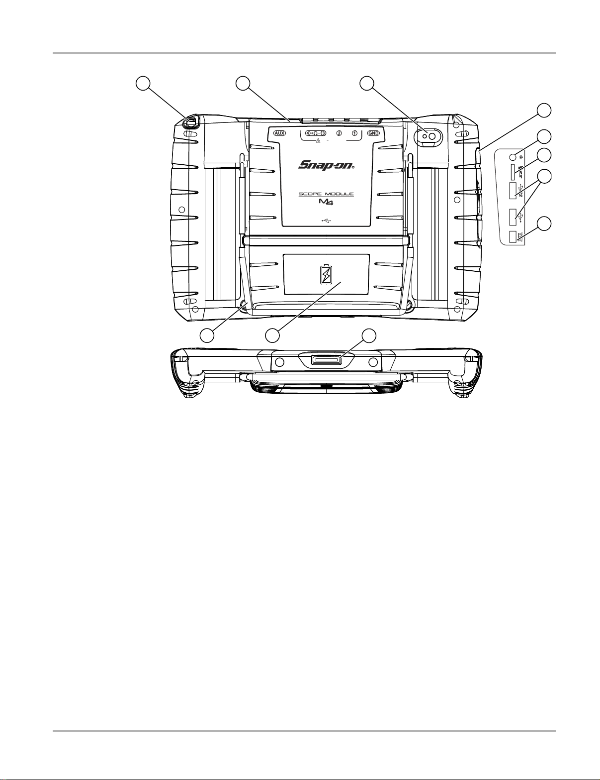
Introduction Features and Specifications
990$;
1— Stylus Storage
2— Scope Module M4 (removable)
3— Camera Lens
4— Communication and Power Jacks Cover
5— Head Phone Jack
6— Micro uSD Card Slot
7— USB (universal serial bus) Jacks (2)
8— DC Power Supply Input Jack
9— Docking Station Connector
10—Battery Pack
11—Collap sible Stand
Figure 2-2
4

Introduction Features and Specifications
Technical Specifications
Item Description / Specification
Touch Screen
Display
Processor
Operating System
Communications
Battery
Power Supply Supply Rating; 19 VDC, 3.4A
DC Operating Voltage
Width
Height
Depth
Weight (including battery
pack without Scope
Multimeter Module)
Weight (including battery
pack and Scope
Multimeter Module)
Operating Temperature
Range (ambient)
Storage Temperature
(ambient)
Environmental
Conditions
Capacitive Touch Panel
10.1 inch diagonal, TFT Color LCD
1280 x 800 resolution (WXGA)
Intel Quad Core N2930, 1.8GHz
Microsoft
®
Windows® Embedded 7
Wi-Fi standard (802.11 b/g/n)
®
Bluetooth
2.1 Technology
Rechargeable Lithium Ion Smart Battery Pack, 11.1VDC
Approximate 5 hour run time
Approximate 3.5 hour charge time
10 to 32 VDC
12.4 in. (316 mm)
8.23 in. (209 mm)
2.0 in. (51 mm)
3.80 lb (1.73 kg)
4.40 lb (2.00 kg)
At 0 to 90% relative humidity (non-condensing)
32 to 113°F (0 to 45°C)
At 0 to 70% relative humidity (non-condensing)
–4 to 140°F (–20 to 60°C)
This product is intended for indoor use only
This product is rated for Pollution Degree 2 (normal conditions)
5

Introduction Features and Specifications
Built-in Stand
The built-in stand extends from the back of the Diag nostic Tool to allow hands-fr ee viewing. The
stand clips into the Diagnostic Tool for storage and pivots out so the display is at a 45 degree angle
when in use.
Power Sources
Your Diagnostic Tool can receive power from any of the following sources:
• Internal Battery Pack
• AC/DC Power Supply
• Vehicle Power
• Docking Sta tion (Optional)
Internal Battery Pack
The Diagnostic Tool can be powered from the internal rechargeable battery pack. A fu lly charged
standard battery pack provides suf ficient po wer for ab out 5 hours of continuou s operation . The
LED backlit power button indicates the battery status.
AC/DC Power Supply
The Diagnostic Tool can be powered from a standard AC outlet using the AC/DC power supply.
When connected to the Diagnostic Tool, the AC/DC power supply also recharges the internal
rechargeable battery pack.
Vehicle Power
The Diagnostic Tool can be powered from a standard 12VDC vehicle power port using the
Diagnostic Tool DC power port adapter . The DC p ower port ada pter connects to the DC power
supply jack on the left side of the Diagnostic Tool.
Docking Station (Optional)
The Diagnostic Tool can be powered (when connected) by the optional docking st ation. Whe n
connected to the docking station, the internal rechargeable battery pack is recharged. Contact
your sales representative for additional details.
6
Introduction Features and Specifications
99 0$;
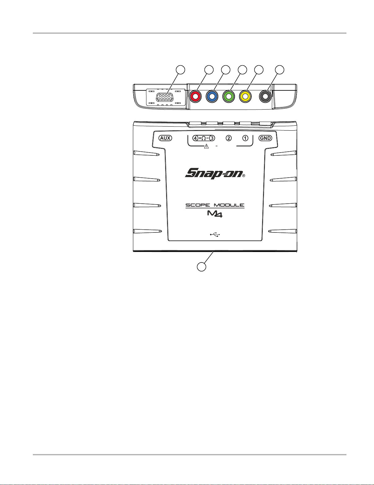
2.1.2 Scope Module
2— Channel 4 Jack
3— Channel 3 Jack
4— Channel 2 Jack
5— Channel 1 Jack
6— Common (Ground) Jack
7— USB Jack (not shown - used for remote operation)
1— Auxiliary (DB9) Connector
Figure 2-3 Scope Module, removed from Diagnostic Tool
7

Introduction Features and Specifications
NOTE:
Remote Operation
If needed, the Scope Module (M4) can be removed from the Diagnostic Tool, then con nected to
the Diagnostic Tool with a USB cable. This increases the range of mobility for the Diagnostic Tool
while monitoring signals on the test vehicle. Use the T y pe A/B USB cable, wh ich is provided with
your kit, to make the connection. For additional information see, Using the Sco pe Module
Remotely on page 85.
i When used remotely, the M4 must be connected to the lower (black) USB jack on the diagnostic
tool. The upper (blue) USB jack should not be used for M4 opera tion.
Technical Specifications
Item Description / Specification
USB Power 5V @ 500mA
Agency Approval -
Rating
Width
Height
Depth
Weight 0.62 lb (0.28 kg)
Operating Temperature
Range (ambient)
Storage Temperature
(ambient)
Environmental
Conditions
IEC 61010-1, UL Listed 61010-1 - Category 1
6.3 in. (160 mm)
4.6 in. (118 mm)
1.1 in. (28 mm)
At 0 to 90% relative humidity (non-condensing)
32 to 113°F (0 to 45°C)
At 0 to 70% relative humidity (non-condensing)
–4 to 140°F (–20 to 60°C)
This product is intended for indoor use only
This product is rated for Pollution Degree 2 (normal conditions)
Power Sources
The Scope Module operates on USB power (5V @ 500mA) supp lied by the Diagn ostic Tool.
Power is provided either through direct connection to the Diagnostic Tool, o r through a USB cable
when the Scope Module is removed from the Diagnostic Tool.
Auxiliary Connector
The auxiliary connector is used for connection of the optional RPM inductive pickup and the
pressure traducer split lead adapter . Fo r additiona l information contact your sales representative
and see, Using the Scope Module Remotely on p age 85.
8
Introduction Features and Specifications
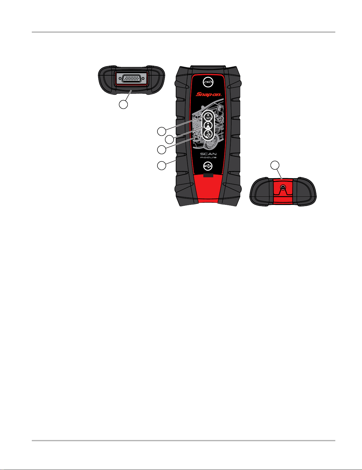
2.1.3 Scan Module (Wireless)
5
($//%
1— Data Cable Connector
2— V ehicle Power LED (green)
3— Communication Issue LED (red)
4— Bluetooth LED (green)
5— Memory Card Port (remove protective hand grip for access)
6— Universal Serial Bus (USB) Jack (remove protective hand grip for access)
Figure 2-4 Scan Module
9

Introduction Features and Specifications
Wireless Communication
The Scan Module is a wireless communications device that transmits vehicle data to the
Diagnostic Tool without a physical connection. A signal lost due to moving out of range
automatically restores itself when the Diagnostic Tool is brought closer to the Scan Module. The
Scanner sounds a tone when the signal is lost.
Technical Specifications
Item Description / Specification
Communications
USB Power 5V @ 500mA
Data Cable Connector
Power
Width
Height
Depth
Weight 0.9 lb (0.408 kg)
Operating Temperature
Range (ambient)
Storage Temperature
(ambient)
Environmental
Conditions
Wireless Bluetooth
8V to 32V, Maximum 12 Watts
8.04 in. (204.3 mm)
3.82 in. (97 mm)
1.66 in. (42.1 mm)
At 0 to 90% relative humidity (non-condensing)
32 to 113°F (0 to 45°C)
At 0 to 70% relative humidity (non-condensing)
–4 to 140°F (–20 to 60°C)
This product is intended for indoor use only
This product is rated for Pollution Degree 2 (normal conditions)
®
2.1 Technology
Power Sources
The Scan Module operates on 12V or 24V vehicle power , which it r eceives through the data cable
connector. The Scan Mo dule powers on whene ver it is connected to an OBD- II/EOBD compliant
data link connector (DLC). For non OBD-II/EOBD compliant vehicles, th e Scan Module can be
powered from a suitable power port on the test vehicle using the auxiliary power cable supplied
with your kit.
10

Chapter 3 Basic Operation and
IMPORTANT:
Navigation
This chapter describes the basic operation, and navigation of the Diagnostic Tool.
3.1 Turning On/Off, Sleep Mode and Emergency
Shutdown
The following sections describe how to turn the Diagnostic Tool on and of f, use Sle ep Mode and
perform an emergency shutdown.
Before using the Diagnostic Tool, make sure the battery is fully charged or is connected to an
AC/DC power supply . see Power Sources on page 6.
3.1.1 Turning On
Press and release the Power button (Figure 2-1) to switch the Diagnostic Tool on. The system
boots up, then opens the Home screen (Figure 3-4).
Table 3-1 Power button
Name Button Description
Power Button / LED
Indicator
3.1.2 Turning Off
All vehicle communication must be terminated BEFORE turning off the Diagnostic Tool. A warning
message displays if you attempt to turn the Diagnostic Tool of f wh ile communicatin g with the
vehicle. Forcing a shut down while communicating may lead to ECM problems on some vehicles.
Never disconnect the Data Cable when the Diagn ostic Tool is commun icating with the vehicle
ECM.
Before turning the Diagnostic Tool off, it is highly recommended to back up person al and saved
data to a USB mass storage device on a regular basis to prevent loss in the event of system
corruption or hard disk drive failure.
z To turn off the Diagnostic Tool:
1. Navigate to the Home screen.
2. Select the Exit icon.
3. From the Windows desktop, open the Windows Start menu.
4. Select T urn Off Computer.
5. Select Turn Off in the dialog box.
The open programs close and the power turns of f.
Turns the Diagnost ic Tool on. See LED Indicator on page 15 for
LED indicator information.
11

Basic Operation and Navigation Turning On/Off, Sleep Mode and Emergency Shutdown
IMPORTANT:
IMPORTANT:
3.1.3 Sleep Mode
The Windows operating system uses Sleep Mode to conserve power by stopping a ll processes
and turning off the display screen, while keeping the diagnostic tool on and your open applications
active. When you are ready to resume work, the dia gnostic tool can be started up again quickly
from the same screen it was on previous to going to sleep.
Sleep Mode settings can be found in Windows Control Pa nel > Power Options . For additional
information, refer to Windows 7 user documentation.
It is recommended that you terminate any current vehicle commu nication and save an y open
working files or data before entering Sleep Mode , to avoid a ny ECM proble ms on some vehi cles
or data loss from any unforeseen circumstances (e.g. power loss).
z To enter Sleep Mode:
• Press and release the Power button.
The display screen will turn off and the LED backlit power button will light up red, blinking on
and off at two second intervals.
z To exit Sleep Mode (wake up):
1. Press and release the Power button.
The display screen will turn on and resume the last open application. Depending on settings,
you may need to select your user ID icon to open the last application.
3.1.4 Emergency Shutdown
Using the emergency shutdown procedure while communicating with the vehicle ECM may lead
to ECM problems on some vehicles.
During normal operation turn the Diagnostic Tool of f using the Turning Off procedure above. The
emergency shutdown procedure should only be used as the last option, if the Diagnostic Tool does
not respond to navigation or control buttons or exhibit s erra tic operation.
To perform an emergency shutdown:
1. Press and release the Power button.
The display screen will turn off and the LED backlit power button will turn red and begin blinking.
2. Press and hold the Power button again, until the LED in the power button stops blinking.
12

Basic Operation and Navigation Shortcut (S) Button
NOTE:
3.2 Shortcut (S) Button
The shortcut (S) button (Figure 3-1) located on the front of the diagnostic tool, and is a
customizable button that can be set to perform various routine functions.
Figure 3-1
i You can open the Shortcut menu at anytime by pressing and holding th e Shortcut (S) button for 3
seconds.
Pressing the shortcut button (Figure 2-1) (when set to open the shortcut menu), opens a slide-out
menu which provides the following selectable icon options:.
Table 3-2
Name Icon Description
Saves a bitmap image (screenshot) of the visible screen. For file
Screen Capture
retrieval and management information, see Data Manager
Operations on page 127.
Camera
Keyboard
Brightness
Settings Opens the Shortcut (S) button configuration menu.
Opens the camera application. See Camera Operation on
page 23 for ad ditional information.
Opens the virtual keyboard. See Virtual Keyboard on page 21
for additional information.
Pressing and releasing the Brightness icon changes the
display brightness setting. Use multiple taps to toggle though
the settings.
13

Basic Operation and Navigation Shortcut (S) Button
3.2.1 Configure Shortcut (S) Button
This feature allows you to change the function of the Shortcut (S) button.
z To configure the Shortcut (S) button:
1. Press and release the Shortcut (S) button.
2. Select the Settings icon from the slide-out menu.
3. Choose the function you would like the Shortcut button to perform when pressed (Figure 3-2).
The current/active setting is indicated by a yellow highlight box.
Figure 3-2 Shortcut (S) button configuration menu
4. Select OK.
3.2.2 Advanced (menu selection)
The Advanced selection has no functionality under normal operatin g conditions, and should ONL Y
be selected when directed to do so, by Snap-on customer service.
Selecting Advanced displays the advanced diagnostic system information screen. The system
state information and functions are ONL Y used during system troubl eshooting, when requested by
Snap-on customer service.
14

Basic Operation and Navigation LED Indicator
3.3 LED Indicator
The power button is backlit by an light emitting diode (LED) (see Figure 2-1 on page 3 for
location). The LED is used to indicate battery/power status and sleep mode activation.
Table 3-3
Name Button
Power Button / LED Indicator
• Battery Sta tus Indicator LED—thr ee colors are u sed to show th e battery an d power status:
– Green indicates either a battery with a full or nearly full charge, or the Diagnostic Tool is
being powered by the AC/DC Power Supply.
– Orange indicates a battery that is charging.
– Red indicates a low battery (15% of capacity or less).
• Sleep Mode:
– A Red LED that blinks on and off at two seco nd intervals indi cates the Diagnostic Tool is
in Sleep Mode. See Sleep Mode on page 12 for additional information.
3.4 Basic Navigation
3.4.1 Touch Screen and Stylus
The capacitive touch screen is used to control almost all the operatio ns of the Diagnostic Tool.
Simply touch the screen with your finger, or use the capacitive stylus to make a selection. The
capacitive touch screen also provides you with multi-touch gesture capabilities found on common
surface touch devices. Most operations are menu driven, which allows you to quickly locate the
test, procedure, or data that you need throu gh a series of ch oices and qu estions. Det ailed
descriptions of the menu structures are found in the ch apters for the various fu nctions.
For information on touch screen calibration, maintenance and stylus tip repla cement:
T ouc h screen calibration - see Calibratin g the Touch Screen on page 182
T ouc h screen maintenan ce - see Cleaning on p age179
Stylus tip replacement - see Stylus Tip Replacement on page 186
15

Basic Operation and Navigation Basic Navigation
Touch Screen Gestures
This device uses common touch screen gesture motions (e.g. pinch-to-zoom, press a nd tap, p an
and swipe). The terms used to describe the various gestures may vary (industry wide), however
the general procedures and usage are similar for spe cific operations.
Table 3-4
Common Gesture
Names
Tap
Touch
Select
Pinch open/close
Pinch-to-zoom
Zoom
Touch and hold
Select and hold
Tap and hold
Touch and drag
Select and drag
Tap and drag
Pan
Quickly tap a point (once), then
release.
Quickly tap a point (twice).
Touch two points, then move your
fingers toward or away from each
other.
Touch a point and maintain light
pressure.
Touch a point, then while maintaining
light pressure, drag in the desired
direction.
General Procedure Common Usage
Make a selection (e.g. open application)
Insert a cursor in a text string
Open alternate menus.
Zoom the display in or out, to make a
selection (e.g. image or picture) larger or
smaller.
Make a selection
Insert a cursor in a text string
Open alternate menus.
Move onscreen controls (e.g. scrollbars
and slidebars)
Move windows
Select text
In a quick and continuous motion,
Swipe
Flick
Press and tap
Select and tap
select a point and quickly swipe in the
desired direction while lifting off the
screen.
Touch a point, then while maintaining
light pressure, tap (in the same
general area) with another finger.
Quickly scroll or move through content
Open alternate menus.
Open alternate menus (similar to right
click).
The information provided in the above table is not inclusive, may vary and is intended as a general
guide only. For additional information on Windows touch screen operations, see Windows 7 and
Windows “touch gesture” user documentation. Also refer to Pe n and Touch settings in the
Windows Control Panel for additional information a nd setting s.
16
Basic Operation and Navigation Basic Navigation
NOTE:
3.4.2 St arting the ShopStream Diagnostic Suite Program
The ShopStre am Diagnostic Suite prog ram is th e ma in progra m which is used fo r all diagno stic
functions. The ShopStream Diagnostic Suite program is automatically started when the
Diagnostic Tool is turned on through the Windows “s tart up” folder function. After the program has
started, the ShopS tr eam Diagno stic Suite Home Screen d isplays, see Home Scr een La yout on
page 17. The application runs as a normal Windows program and it’s window can be minimized,
resized and closed like any other Windows program. To access the Windows desktop, minimize
the program window .
If the program is exited or closed, select the ShopS tream Diagnostic Suite icon from the Windows
desktop to start the program.
Figure 3-3 ShopStream Diagnostic Suite desktop icon
i The ShopStream Diagnostic Suite can also be starte d from the Wind ows Start menu.
3.4.3 Home Screen Layout
The Home screen includes the diagnostic suite toolbar and th e Windows taskbar. The Home
screen includes function icons, one for each of the primary Diagnostic Tool functions.
6FDQQHU
9HKLFOH
+LVWRU\
+RPH 'HVNWRS 0HQX 76% &KDQJH9HKLFOH 9LHZ5HFRUG +DUGZDUH6WDWXV
2%''LUHFW
76%
*XLGHG
&RPSRQHQW
7HVWV
'DWD
0DQDJHU
0XOWLPHWHU
6FRSH
+HOS
6XUH7UDFN
6\VWHP
6HWWLQJV
5HSDLU
,QIRUPDWLRQ
([LW
1. Function Icons
2. Toolbar
3. Windows Taskbar
4. Windows Taskbar Notification Area
Figure 3-4 Home screen
17
Basic Operation and Navigation Basic Navigation
3.4.4 Function Icons
The Function Icons configure the Diagnostic Tool for the type of test to be performed. Table 3-5 on
page 18 gives brief descriptions of the available icons, which operations are availa ble dep ends
upon the individual configuration of your system. Use the stylus or your finger tip to select from the
icons.
Table 3-5 (table 1 of 2)
Name Icon Description
Configures the Diagnostic Tool to operate
Scanner
OBD Direct
as a scan tool. See Scanner Function on
page 25.
Allows you to perform generic OBD-II or
EOBD system tests without identifying the
specific vehicle. See OBD Direct
Operations on page 66.
Guided Component
Test
Scope Multimeter
SureTrack
Repair Information
TSB
Vehicle History
®
Opens a diagnostic database of specific
tests for the identified vehicle. See Guided
Component Test Operations on page 74.
Configures the Diagnostic Tool to operate
as a lab scope, graphing multimeter, or
digital multimeter. See Scope and
Multimeter Operations on page 85.
Opens the SureTrack website. See
SureTrack on page 153.
Provides the information needed to make
repairs once you have made your
diagnosis. The linked program varies by
region. See Repair Information on
page 115.
Provides technical service bulletin, recall
and campaign information (if available) for
the identified vehicle. See TSB (Technical
Service Bulletins) on page 117.
Identifies the test vehicle and organizes and
manages work in progress and service
records. See Vehicle History Operations on
page 122.
Data Manager
Opens the organization system for saved
data files. See Data Manager Operations on
page 127.
18
Basic Operation and Navigation Basic Navigation
Table 3-5 (table 2 of 2)
Name Icon Description
Help
System Settings
Exit
3.4.5 Toolbar
Operation of the icons located on the toolbar are described in the t able belo w:
Table 3-6
Name Icon Description
Home
Desktop
Menu
Technical Service
Bulletins
Change Vehicle
Opens the on-line help for the system. See
Help Operations on page 145.
Establishes and manages connections to
peripheral devices, such as the Scan
Module. See System Settings Operations
on page 146.
Closes the Diagnostic Tool software and
returns the display to the Windows desktop.
See Turning Off on page 11.
Selecting this icon returns you to the Home
screen from any test.
Selecting this icon toggles the Windows
taskbar on/off at the bottom of the screen,
and allows you access to the Windows
desktop.
Selecting this icon opens a menu that
provides information and basic operations
and features for the current screen.
Provides Technical Service Bulletin
information (if available) for the identified
vehicle. See TSB (Technical Service
Bulletins) on page 117.
The currently identified vehicle is shown to
the right of the icons, selecting allows you to
change the identified test vehicle.
View Record
Hardware Status
Selecting the icon opens an editable
worksheet of vehicle records.
Indicates the connectivity status of the Scan
Module. Icon changes depending on status.
Indicates the connectivity status of the
Scope Multimeter. Icon changes depending
on status.
19

Basic Operation and Navigation Basic Navigation
Menu Options
The Menu icon on the Toolbar at the base of th e display scr een opens a list of ba sic operation s
and features. The list of options varies depending upon which module, or to ol function, is active.
Selecting a menu item opens a submenu of choices, and some submenus also open a n additional
menu. A right arrowhead (
it. The following Menu options are available from the Home Screen:
• Safety Information—opens the Important Safety Instructions document.
• Help—allows you to view supporting documentation, selectin g open s a su bmenu.
Safety Information
Selecting Safety Information opens a PDF copy of the Important Safety Instructions that are
included in your Diagnostic Tool kit. The Important Safety Instructions document should be read
and understood prior to using the Diagnostic Tool.
Help
A variety of utilities and additional resources are available through the Help menu. Basic menu
options, which are available for all modules, include:
) indicates additional choices are available. Touch an item to select
• User Manual
• Vers ion Info
• Activation Status
User Manual
This option opens this document, which provides overall navigation and operation infor mation for
the Diagnostic T ool.
Version Info
This option opens a window showing the version of the software and a co py of the Sof t ware
License Agreement. Select OK to close the window.
Activation Status
This option opens a dialog box with version and licensing details for the system, and activation
status for the Diagnostic Tool and all other modules.
20
 Loading...