

Page 1

Step-by-step how
to use instructions
EEWB334A
OPERATOR’S MANUAL
MANUEL OPÉRATEUR
BEDIENUNGSANLEITUNG
Page 2
ii
Snap-On EEWB334AP
Snap-on Equipment Srl a unico socio
Via Provinciale per Carpi, 33
42015 CORREGGIO (RE) ITALY
Tel.: +39-(0)522-733480
Fax: +39-(0)522-733479
E-mail: corrcs@snapon.com
Internet: http://www.snapon-equipment.eu
EC DECLARATION (Original document contained in Spare Parts Booklet)
DECLARATION CE (Le document original fi gurant dans le Liste des pièces détachées)
CE KONFORMITÄTSERKLÄRUNG (Originaldokument in der Ersatzteilliste enthaltenen)
ДЕКЛАРАЦИЯ EC (Оригинал документа прилагается к ведомости запчастей)
DICHIARAZIONE CE (Originale contenuta nel Libretto Ricambi)
DECLARACIÓN CE (El original se encuentra en tabla de repuestos)
DECLARAÇÃO CE (O original está contida em Lista de peças)
- FACSIMILE - ФАКСИМИЛЕ -
FAMILY NAME MODELS DESCRIPTION
All Information in this manual has been supplied by the producer of the equipment:
Toutes les informations fi gurant dans le présent manuel ont été fournies par le fabricant de l’équipement :
Alle in diesem Handbuch enthaltenen Informationen wurden durch den Hersteller der Maschinen geliefert:
Вся информация, содержащаяся в данном руководстве, предоставлена производителем оборудования
Tutte le informazioni contenute nel presente manuale sono fornite dal produttore dell’apparecchiatura:
Todas las informaciones contenidas en este manual han sido facilitadas por el productor del equipo:
Todas as informações contidas neste manual foram fornecidas pelo produtor da máquina:
Alle informatie van deze handleiding wordt geleverd door de aangegeven Technische Afdeling van Snap-on:
EEWB334AP
EEWB334A
EEWB334AP Power clamp
Page 3
iii
Snap-On EEWB334AP
Wiring Diagram
Schaltplan
Schéma électrique
Схема электрических соединений
Schema Elettrico
Esquema Eléctrico
Esquema Eléctrico
Elektrisch schema
Contenuto in SP
Integradas en SP
Conteúdos em SP
Opgenomen in SP
Contained in SP
Teil der SP
Contenu dans SP
Содержит
ся в каталоге запчастей
date of fi rst publication:
date de la première édition:
Datum der Erstveröffentlichung:
data di prima pubblicazione:
fecha de la primera publicación:
data da primeira publicação:
дата первой публикации:
eerste publicatiedatum:
Product aid publication:
WHEEL BALANCER
Zum Produkt gehörendes Dokument:
AUSWUCHTMASCHINEN
Publication de support au produit:
EQUILIBREUSE
Pubblicazione di supporto al prodotto:
EQUILIBRATRICE
Publicación de soporte al producto:
EQUILIBRADORA
Documentação de apoio ao produto:
MÁQUINA DE EQUILIBRAR RODAS
Публикация для поддержки изделия:
БАЛАНСИРОВОЧНЫЙ СТАНОК
Ondersteunende publicatie van het product:
BALANCEERMACHINE
Original language edition in: ITALIAN
Langue d’origine de la publication: ITALIEN
Originalausgabe in: ITALIENISCH
Edizione di lingua originale in: ITALIANO
Edición original en idioma: ITALIANO
Edição original em: ITALIANO
язык оригинального издания: АНГЛИЙСКИЙ
Vertaling van de originele uitgave in het: ITALIAANS
DOCUMENTATION SUPPLIED
GELIEFERTE DOKUMENTATION
DOCUMENTATION FOURNIE
ПОСТАВЛЯЕМЫЕ ДОКУМЕНТЫ
DOCUMENTAZIONE FORNITA
DOCUMENTACIÓN SUMINISTRADA
DOCUMENTAÇÃO FORNECIDA
GELEVERDE DOCUMENTATIE
DICHIARAZIONE CE
DECLARACIÓN CE
DECLARAÇÃO CE
CE-VERKLARING
EC DECLARATION
CE KONFORMITÄTSERKLÄRUNG
DECLARATION CE
ДЕКЛАРАЦИЯ ЕС
EC
WD
EC
WD
ENG - NOTES REGARDING DOCUMENTATION
DEU -
ANMERKUNGEN ZUR DOKUMENTATION
FRA - NOTES SUR LA DOCUMENTATION
RU - ПРИМЕЧАНИЯ ПО ДОКУМЕНТАЦИИ
NOTE SULLA DOCUMENTAZIONE - ITA
NOTAS SOBRE LA DOCUMENTACIÓN - SPA
NOTAS SOBRE A DOCUMENTAÇÃO - POR
OPMERKINGEN OVER DE DOCUMENTATIE - NL
2016 / 02
ABB.
SIGLE
KENN.
DESCRIPTION
DESCRIPTION
BESCHREIBUNG
CODE
CODE
CODE
LANGUAGE
LANGUE
SPRACHE
O
M
OM
SP
Operator’
s Manual
Manuel de l’Opérateur
Betriebsanleitung
Руководство по эксплуатации
Handleiding
ZEEWB334AE03
ZEE
WB334AE08
ENG-FRA-DEU
RU-NL
Spare Parts Booklet
Liste des pièces détachées
Ersatzteilliste
Запчасти Буклет
TEEWB334AE3
ENG-FRA-DEU
ITA-SPA-POR
RU-NL
ENG-FRA-DEU
RU
EAZ0090G58A
EAZ0090G60A
Safety and Quick Start
Securité et Démarrage Rapide
Sicherheit und schneller Start
Безопасность и быстрый запуск
Veiligheid en Snelle Start
SIGLA
SIGLA
SIGLA
DESCRIZIONE
DESCRIPCIÓN
DESCRIÇÃO
CODICE
CÓDIGO
CÓDIGO
LINGUA
IDIOMA
IDIOMA
OM
OM
SP
ZE
EWB334AE05
TEEWB334AE3
EAZ0090G59A
ITA-POR-SPA
ITA-POR-SPA
ENG-FRA-DEU
ITA-SPA-POR
RU-NL
Manuale Operatore
Manual de Operador
Manual do Operador
Libretto Ricambi
Tabla de repuestos
Lista de peças
Reserveonderdelen-boekje
Sicurezza e Avvio Rapido
S
eg
urança e Arranque Rápido
Seguridad y Arranque Rápido
Page 4

iv
DISCLAIMER OF WARRANTIES
AND LIMITATIONS OF LIABILITIES
While the authors have taken care in the preparation
of this manual, nothing contained herein:
- modi! es or alters in any way the standard
terms and conditions of the purchase, lease or
rental agreement under the terms of which the
equipment to which this manual relates was
acquired,
- increases in any way the liability to the customer
or to third parties.
TO THE READER
While every effort has been made to ensure that
the information contained in this manual is correct,
complete and up-to date, the right to change any part
of this document at any time without prior notice is
reserved.
Before installing, maintaining or
operating this unit, please read
this manual carefully, paying extra
attention to the safety warnings
and precautions.
Table of Contents
Disclaimer of warranties v
1.0
Safety 7
2.0 Specifi cations 9
3.0
Introduction 11
4.0 Layout 15
5.0 Operation 35
6.0 Maintenance 87
7.0 Trouble shotting 93
8.0 Disposing of the unit 117
9.0 Appendix 117
Appendix: Installation Instructions 119
UPDATING REPORTS
Release A -_________________- March 2016
First Release
New model machine - PCN: 15G0469
Page 5

v
GEWÄHRLEISTUNGS- UND
HAFTUNGSAUSSCHLUSS
Die Informationen in dieser Bedienungsanleitung wurden
gewissenhaft und sorgfältig zusammengestellt. Der Inhalt
oder Teile des Inhalts dieser Bedienungsanleitung:
- haben keinen Einfluß auf die Allgemeinen
Geschäftsbedingungen des Kaufvertrages,
Leasingvertrages oder Mietvertrages auf dessen
Grundlage das in dieser Bedienungsanleitung
beschriebene Maschine bezogen wurde,
- erweitern in keiner Weise den Haftungsanspruch
des Kunden oder Dritter.
AN DEN LESER
Be i d er Z us am m en st e ll un g d e r i n d ie ser
Bedienungsanleitung enthaltenen Informationen wurde
größten Wert auf deren Richtigkeit, Vollständigkeit und
Aktualität gelegt. Wir behalten uns jedoch ausdrücklich
das Recht vor, diese Informationen jederzeit und ohne
vorherige Ankündigung zu ändern.
Lesen Sie diese
Bedienungsanleitung sorgfältig
durch, bevor Sie die Maschine
installieren, warten oder betreiben.
Beachten Sie insbesondere die
Sicherheitsvorschriften und
Warnungen.
Inhaltsverzeichnis
Gewährleistungs
iv
1.0 Sicherheit 6
2.0 Spezifi
kationen 8
3.0 Einfürung 10
4.0 Layout 14
5.0 Betrieb 34
6.0 Wartung 86
7.0 Fehlerbeseitigung 92
8.0 Entsorgung 116
9.0 Anhang 116
Anhang: Installationsanweisugen 119
LIMITES D’APPLICATION DE LA GARANTIE ET
LIMITATIONS DE LA GARANTIE
Bien que les auteurs aient accordé la plus grande
attention à la rédaction du présent manuel, aucun
élément ! gurant dans ce dernier:
- ne modi! e les conditions et les termes standards
d’un accord d’achat en crédit-bail ou de location,
aux termes desquels les appareils traités dans
le présent manuel sont achetés,
- ou n’augmente la responsabilité de la société
envers le client ou les tiers.
POUR LE LECTEUR
Bien que tout effort ait été fait pour assurer l’exactitude
des informations ! gurant dans le présent manuel,
comme complément ou mise à jour de ce dernier, le
droit d’y apporter des modi! cations à tout moment sans
préavis est réservé.
Avant d’installer, d’entretenir ou d’uti-
liser la machine, lire attentivement le
présent manuel, en faisant particuliè-
rement attention aux avertissements
et précautions de sécurité.
Table des matieres
Aapplication de la garantie v
1.0
Sécurité 7
2.0
Specifi cations 9
3.0 Introduction 11
4.0 Disposition 15
5.0 Utilisation 35
6.0 Entretien 87
7.0 Dépannage 93
8.0 Vente 117
9.0 Annexes 117
Annexe: Instructions d’Installation 119
Page 6

6
1-1
WICHTIG!!
DIESE ANLEITUNG IST AUFZUBEWAHREN
IMPORTANT!!
CONSERVER LES PRÉSENTES INSTRUCTIONS
Safety
1.0 Safety
The Safety Precautions should be fully understood and
observed by every operator. The Operator’s Manual
will contain specific warnings and cautions when
dangerous situations may be encountered during the
procedures described.
Important safety precautions relevant to the unit are
described in the Safety Booklet, refer to Figure 1 – 1.
We suggest you store (a copy) of the Safety Booklet
near the unit, within easy reach of the operator.
1.1 Typographical conventions
This manual contains text styles intended to make the
reader pay extra attention:
Note:
Suggestion or explanation.
CA
UTION: INDICATES THAT THE FOLLOWING
ACTION MAY RESULT IN DAMAGE TO THE UNIT
OR OBJECTS ATTACHED TO IT.
WARNING: INDICATES THAT THE FOLLOWING
ACTION MAY RESULT IN (SERIOUS) INJURY TO
THE OPERATOR OR OTHERS.
• Bulleted list:
• Indicates that action must be taken by the operator
before proceeding to the next step in the sequence.
TOPIC (F n°) = see the Chapter number.
The topic indicated is explained in full in the charter
speci! er.
1.2 Manuals for the unit
The unit includes the following documentation:
-
Gui
da all’Installazione e alla Sicurezza
(standard supplement Fig. 1-1).
Installation instructions
Further installation instructions are in the Appendix
of the Operator Manual.
- Operator’s Manual (available on web).
The operator must learn in detail the instructions
contained in them and meticulously observe the
notes HAZARD and CAUTION WARNINGs.
- Spare Parts Booklet
Document used only by the Technical Support staff.
EC Declaration of Conformity
The EC Declaration is included in the Spare Parts
Booklet.
IMPORTANT!!
SAVE THESE INSTRUCTIONS
P/N: EAZ0090G58A
Page 7

7
Sicherheit
1.0 Sicherheit
Die Sicherheitsmaßnahmen müssen von allen
Bedienern verstanden und eingehalten werden.
D
as Bedienungshandbuch enthält spezifische
Warnungen und Hinweise, wenn bei den beschriebenen
Maßnahmen gefährliche Situationen auftreten können.
Wichtige Sicherheitsmaßnahmen für dieses Gerät sind
im Sicherheitshandbuch beschrieben; siehe Abbildung
1-1. Wir empfehlen, eine Kopie des Sicherheitshefts
in der Nähe des Geräts gut sichtbar für den Bediener
aufzubewahren.
1.1 Typographie
Dieses Handbuch enthält Schriftweisen, die zu
besonderer Vorsicht auffordern:
Anmerkung:
Vorschlag oder Erklärung
VORSICHT: WEIST DARAUF HIN, DASS DIE
FOLGENDE MASSNAHME ZU SCHÄDEN AM
GERÄT ODER DARAN BEFESTIGTEN TEILEN
FÜHREN KANN.
WARNUNG: WEIST DARAUF HIN, DASS DIE
FOLGENDE MASSNAHME ZU (SCHWEREN)
VERLETZUNGEN DES BEDIENERS ODER
ANDERER PERSONEN FÜHREN KANN.
• Aufzählungspunkte:
• Zeigen an, dass der Bediener Maßnahmen
durchführen muss, bevor er zum nächsten Schritt
des Vorgangs übergehen kann.
THEMA F Nr. (= siehe Kapitel Nummer).
Das angegebene Thema wird in dem bezeichneten
Kapitel ausführlich behandelt.
1.2 Handbücher des Geräts
Das Gerät ist mit folgender Dokumentation ausgestattet:
-
Booklet für Sicherheit und Installationshandbuch
(Standardbeilage Abb. 1-1).
- Betriebsanleitung (im Internet verfügbar).
Der Be n utzer m u ss die d a rin ent h altene n
Anweisungen im Detail erfassen und die Hinweise,
die WARNUNGEN vor Gefahren und die Angaben mit
der Bezeichnung ACHTUNG genauestens befolgen.
- Ersatzteilhandbuch
Dieses Dokument ist dem Wartungspersonal
vorbehalten.
Installationsanweisungen
Die Installationsanweisungen ! nden Sie in der
Anlage der Betriebsanleitung.
CE-Konformitätserklärung
Die CE-Konformitätserklärung be! ndet sich im
Ersatzteilhandbuch.
Sécurité
1.0 Sécurité
Chaque opérateur doit totalement comprendre les
mesures de sécurité.
L
e Manuel de l’Opérateur contient des avertissements
et des mesures de prudence spécifiques à des
situations potentiellement dangereuses qui peuvent
se produire durant les procédures décrites.
Les mesures de sécurité importantes relatives à l’unité
sont décrites dans le Livret de Sécurité et résumées
Fig.1-1.
Nous suggérons de conserver une copie du Livret de
Sécurité près de la machine à la portée de l’opérateur.
1.1 Typographie
Ce manuel contient des styles de texte qui vous
demande de prêter une attention particulière :
Remarque : Suggestion ou explication.
ME
SURE DE PRUDENCE : INDIQUE QUE L’ACTION
SUIVANTE RISQUE D’ENDOMMAGER LA MACHINE
ET DES OBJETS ATTACHES A LA MACHINE.
AVERTISSEMENT : INDIQUE QUE L’ACTION
SUIVANTE RISQUE DE CAUSER DES BLESSURES
(SERIEUSES) A L’OPERATEUR OU AUTRES.
• Liste à puces :
• Indique que l’opérateur doit effectuer une action
avant de pouvoir passer à l’étape suivante de la
séquence.
ARGUMENTO (F n°) = ir para o número do capítulo.
A actualização indicada è tratada dentro do capítulo
especi! cado.
1.2 Manuels de la machine
La machine est accompagnée des manuels suivants:
- Liv
ret pour la Sécurité et guide de installation
(supplément de norme Fig. 1-1).
Instructions pour l’installation
D’autres instructions d’installation se trouvent dans
l’Appendice du Manuel d’utilisation.
- Manuel d’utilisation (disponible sur le web).
L’utilisateur doit apprendre dans le détail les
instructions que ce manuel contient et observer
scrupuleusement les remarques, les MISES EN
GARDE de danger et d’ATTENTION
-
Tables et Listes des Pièces de Rechange
Document à usage exclusif du personnel d’assistance.
Déclaration de Conformité CE
La Déclaration CE ! gure dans la Notice des Pièces
détachées.
Page 8

8
230V~, 50/60 Hz, 1 ph
1,1 A
0,12 KW
(2x)IEC 127 T 6,3A
6-8 sec.
200 rpm
0–290 mm
1/5 g (0,05/0,25 oz)
508 mm (20”)
1066 mm (42”)
70 Kg (154 lbs)
76-508 mm (3-20”)
8-25” / 8-32”
13-26”
40 mm
225 mm (8.9 inch)
130 Kg (286 lbs)
160 Kg (353 lbs)
1313x870x1835 mm
(51.7” x 34.2” x 72.2”)
1300x1120x1262 mm
(51.2” x 44.1” x 49.7”)
<70 db(A)
0-50 °C
10-90%
Speci! cations
2.0 Specifi cations
Power:
Power Supply
Power consumption
Motor rating
Mains fuses
Measurements:
Measuring time
Measuring speed
O
ffset
Resolution
Wheel dimensions:
Max. width
Max. diameter
Max. weight
Rim width
Rim diameter:
- Automatic / Manual
- SMART SONAR
Shaft:
Stub shaft diameter
Stub shaft Lenght
Dimensions:
Weight
Shipping weight
Max. Dimensions (wxdxh)
Shipping dimensions (max)
Miscellaneous:
Noise level
2.1 Conditions
During use or long term storage, the conditions shou
ld
never exeed:
Temperature range
Humidity range
non condensing
Page 9

9
230V~, 50/60 Hz, 1 ph
1,1 A
0,12 KW
(2x)IEC 127 T 6,3A
6-8 sec.
200 rpm
0–290 mm
1/5 g (0,05/0,25 oz)
508 mm (20”)
1066 mm (42”)
70 Kg (154 lbs)
76-508 mm (3-20”)
8-25” / 8-32”
13-26”
40 mm
225 mm (8.9 inch)
130 Kg (286 lbs)
160 Kg (353 lbs)
1313x870x1835 mm
(51.7” x 34.2” x 72.2”)
1300x1120x1262 mm
(51.2” x 44.1” x 49.7”)
<70 db(A)
0-50 °C
10-90%
230V~, 50/60 Hz, 1 ph
1,1 A
0,12 KW
(2x)IEC 127 T 6,3A
6-8 sec.
2
00 rpm
0–290 mm
1/5 g (0,05/0,25 oz)
508 mm (20”)
1066mm (42”)
70 Kg (154 lbs)
76-508 mm (3-20”)
8-25” / 8-32”
13-26”
40 mm
225 mm (8.9 inch)
130 Kg (286 lbs)
160 Kg (353 lbs)
1313x870x1835 mm
(51.7” x 34.2” x 72.2”)
1300x1120x1262 mm
(51.2” x 44.1” x 49.7”)
<70 db(A)
0-50 °C
10-90%
Spezi! kationen
2.0 Spezifi kationen
Strom:
Stromversorgung
Stromverbrauch
Motorwerte
Netzsicherungen
Daten:
Messzeit
Messdrehzahl
Abstand Maschine/Felgenhorn
Au" ösung
Radmaße:
Max. Breite
Max. Durchmesser
Max. Gewicht
Felgenbreite
Felgendurchmesser:
- Automatisch / Manuell
- SMART SONAR
Welle:
Hauptwellendurchmesser
Steckwelle Länge
Maße:
Gewicht
Versandgewicht
Max. Maße (BxTxH)
Versandmaße (max)
Anderes:
Geräuschpegel
2.1 Bedingungen
Während der Benutzung bzw. einer Langzeitlagerung
dürf
en die folgenden Werte nicht überschritten werden.
Temperaturbereich
Luftfeuchtigkeitsbereich
nicht kondensierend
Speci! cations
2.0 Specifi cations
Données électrices :
Alimentation
Consommation électrique
Puissance moteur
Fusibles
Mesures :
Durée des mesures
V
itesse rotation
Ecart
Résolution
Dimensions de roue :
Largeur max.
Diamètre max.
Poids max.
Largeur de la jante
Diamètre de la jante:
- Automatique / manuel
- SMART
SONAR
Arbre :
Diamètre de bout d’arbre
Longueur de bout d’arbre
Misure:
Poids
Poids d’expédition
Dimensions max. (lxdxh)
Dimensions d’expédition (max)
Divers :
Niveau sonore
2.1 Conditions
Lors d’une utilisation ou un stockage prolongé les
conditions ne doivent jamais dépasser :
Gamme de températures
Gamme d’humidité
sans formation de buée
Page 10

10
Introduction
3.0 Introduction
This wheel balancer combines advanced, highperformance technology, robustness and reliability
with very simple, user-friendly operation.
The colour monitor shows the data set, operating
modes, values measured, symbols and operator help
information. The touch-screen monitor also includes
all Operating Controls.
Operator time and effort are reduced to a minimum,
while maintaining accuracy and reliability.
Always work in a clean area and with clean wheels.
First remove dirt and old weights from tyres and rims.
That way proper mounting of the wheel and an optimal
balancing result can be achieved.
Application
The off-the-vehicle wheel balancer is designed for
dynamic and static balancing of passenger car and
light-truck wheels, that fall within the limits stated in
the technical speci! cations (F 2).
This is a high accuracy measuring device. Handle with care.
Page 11

11
Einführung
3.0 Einführung
Dieses Auswuchtgerät verbindet hochmoderne
Hochleistungstechnik, Robustheit und Zuverlässigkeit
mit einfachem, benutzerfreundlichem Betrieb.
Auf dem Farbmonitor werden eingegebene Daten,
Betriebsarten, die jeweils ermittelten Messwerte sowie
bedienerführende Symbole und Hinweise angezeigt.
Außerdem enthält der Touchscreen-Monitor sämtliche
Steuerungselemente für den Betrieb.
Die Zeit und der Aufwand zur Bedienung sind
extrem gering, ohne jedoch die Genauigkeit und die
Zuverlässigkeit zu beeinträchtigen.
Arbeiten Sie immer in einer sauberen Umgebung und
mit sauberen Rädern; entfernen Sie Rückstände und
alte Gewichte von Reifen und Felgen. Dadurch ist
sichergestellt, dass das Rad richtig aufgespannt wird
und eine optimale Auswuchtung erzielt wird.
Einsatzbereich
Das Auswuchtgerät für demontierte Räder wurde zur
statischen und dynamischen Auswuchtung von Rädern
von Personenkraftwagen und leichten Lkws entwickelt,
die in den Bereich der angegebenen technischen
Spezi! kationen fallen (F 2). Dies ist ein hochgenaues
Messgerät. Behandeln Sie es p" eglich.
Introduction
3.0 Introduction
Cette équilibreuse vous offre une technologie avancé
e
de haute performance, solidité et fiabilité et son
opération est très simple et conviviale.
Sur le moniteur couleur sont af! chées les données
entrées, les modes de fonctionnement, les valeurs
mesurées respectives et le guide pour l’opérateur.
L’écran tactile contient aussi toutes les commandes
pour l’opérativité. Le temps et l’effort d’utilisation sont
réduits au minimum mais la précision reste constante.
Travaillez toujours dans un endroit propre avec des
roues propres ; débarrassez les pneus et les jantes
de la saleté et des masses qui ne servent plus. Ainsi
vous obtiendrez une installation correcte de la roue et
des résultats d’équilibrage parfaits.
Application
Cette équilibreuse roues démontéespermet de mesurer
ledéséquilibre dynamique et statique des roues de
voitures et de camionnettes, qui se trouvent dans les
limites mentionnées des spéci! cations techniques (F 2).
Ceci est un appareil de mesure de haute précision.
Manipuler avec soin.
Page 12
12
EAM0005D45A
EAM0005D54A
EAC0058D15A
EAC0058D07A
EAC0058D08A
EAM0005D25A
EAM0005D24A
EAM0005D23A
EAM0005D40A
EAA0247G22A
EAA0247G21A
3.1-1
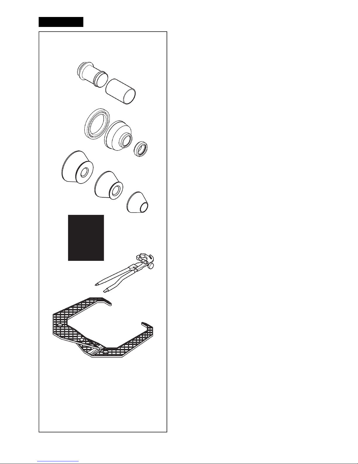
Accessories
3.2 Accessories
Refer to Figure 3.1-1.
The standard accessories are:
Power Clamp Nut
Plastic Sleeve
Universal drum cushion
Universal drum
Spacer ring
Large cone
Medium cone
Small cone
User Calibration weight
W
eight pliers
Caliper
Page 13

13
EAM0005D45A
EAM0005D54A
EAC0058D15A
EAC0058D07A
EAC0058D08A
EAM0005D25A
EAM0005D24A
EAM0005D23A
EAM0005D40A
EAA0247G22A
EAA0247G21A
EAM0005D45A
EAM0005D54A
EAC0058D15A
EAC0058D07A
EAC0058D08A
EAM0005D25A
EAM0005D24A
EAM0005D23A
EAM0005D40A
EAA0247G22A
EAA0247G21A
Zubehör
3.2 Zubehör
Siehe Abbildung 3.1-1.
Das folgende Standardzubehör steht zur Verfügung:
Power Clamp Spannmutter
Druckmuffe aus Kunststoff
Schützring für Drucktopf
Drucktopf
Distanzring
Großer Konus
Mittlerer Konus
Kleiner Konus
Benutzerkalibriergewicht
Gewichtzange
Meßlehre
Accessoires
3.2 Accessoires
Se reporter à la Figure 3.1-1.
Les accessoires standard sont:
Embout de blocage Power Clamp
Manchon en plastique
Joint protection de la coupelle
Coupelle plastique
Disque de distance
Grand cône
Cône moyen
Petit cône
Masse de calibrage utilisateur
Pince à masses
Calibre largeur jantes
Page 14
14
4-1
4-2
3
1
2
4
5
3a
6
8
2
1
9
7
3b
1
2
3
4-3
10
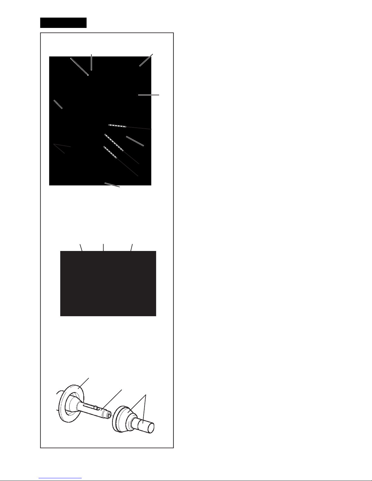
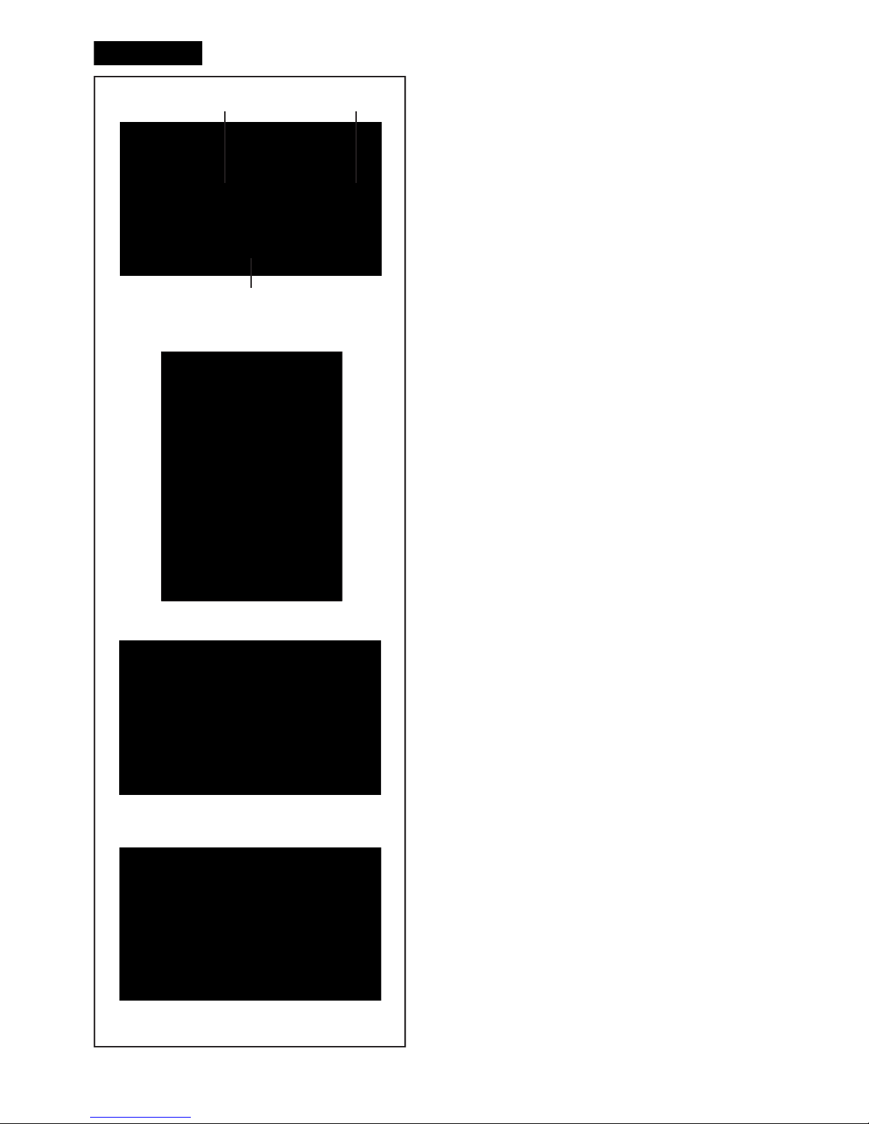
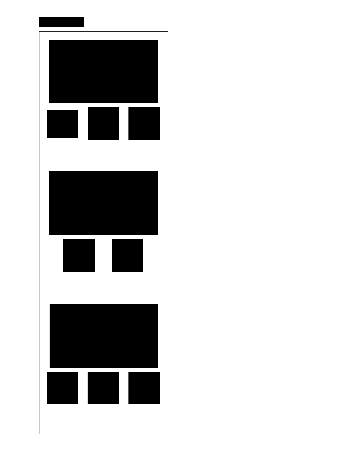
Layout
4.0 Layout
Refer to Figure 4-1.
Functional description of the unit:
1.
Display
Refer to Chapter 4.1.
2. Input panel
Refer to Chapter 4.1.2
3a
Internal gauge arm
3b External Detector - Sonar
4. Flange
5. Stub shaft
6. Weight compartments
7. Storage areas for cones and hub nuts
8. Wheel guard
9. Control pedal (Brake / Power Clamp)
10. Laser Pointer (F 4.6)
Refer to Figure 4-2.
1.
Mains switch (ON/OFF)
2. Fuse holder
3. Power inlet
Refer to Figure 4-3
Power clamping device
1 Basic body of clamping device (Flange)
2
Chuck and clamping jaws
3 Clamping sleeve and head
Page 15

15
Layout
4.0 Layout
Siehe Abbildung 4-1.
Funktionsbeschreibung des Geräts:
1.
Berührungseingabe Bildschirm
Siehe Kapitel 4.1.
2. Eingabefeld
Siehe Kapitel 4.1.2
3a Innerer Messarm
3b Messgerät für das Außen - Sonar
4. Flansch
5. Flanschwelle
6. Gewichtefächer
7. Aufbewahrungsbereiche für Konen oder Spannteile
8. Radschutz
9. Steuerpedal (Bremse/ Power Clamp)
10. Laserzeiger (F 4.6)
Siehe Abbildung 4-2.
1. Netzschalter (AN/AUS)
2. Sicherungshalter
3. Netzanschluss
Siehe Abbildung 4-3
Spannvorrichtung Power Clamp
1 Grundkörper
der Spannvorrichtung (Flanschwelle)
2 Spannfuttter mit Spannklauen
3 Spannhülse mit Drucktopf
Disposition
4.0 Disposition
Se reporter à la Figure 4-1.
Description fonctionnelle de la machine :
1. Affi
chage
Se reporter au Chapitre 4.1
2.
Clavier
Se reporter au Chapitre 4.1.2
3a Jauge de déport interne
3b Capteur externe - Sonar
4. Montage
5. Embout d’arbre
6. Bac porte-plombs
7. Zones de stockage pour cônes et outils de
blocage
8. Carter de roue
9. Pédale commande (Frein / Power Clamp)
10. Pointeur Laser (F 4.6)
Se reporter à la Figure 4-2.
1. Interrupteur secteur (ALLUMÉ / ÉTEINT)
2.
Porte-fusible
3. Branchement electrique
Se reporter à la Figure 4-3
Moyen de serrage power clamp
1 Corps de base du moyen de serrage (Montage)
2
Mandrin avec mors de serrage
3 Douille et tête de serrage
Page 16
16
4-3
4-4
3
21
4-5
4-3b
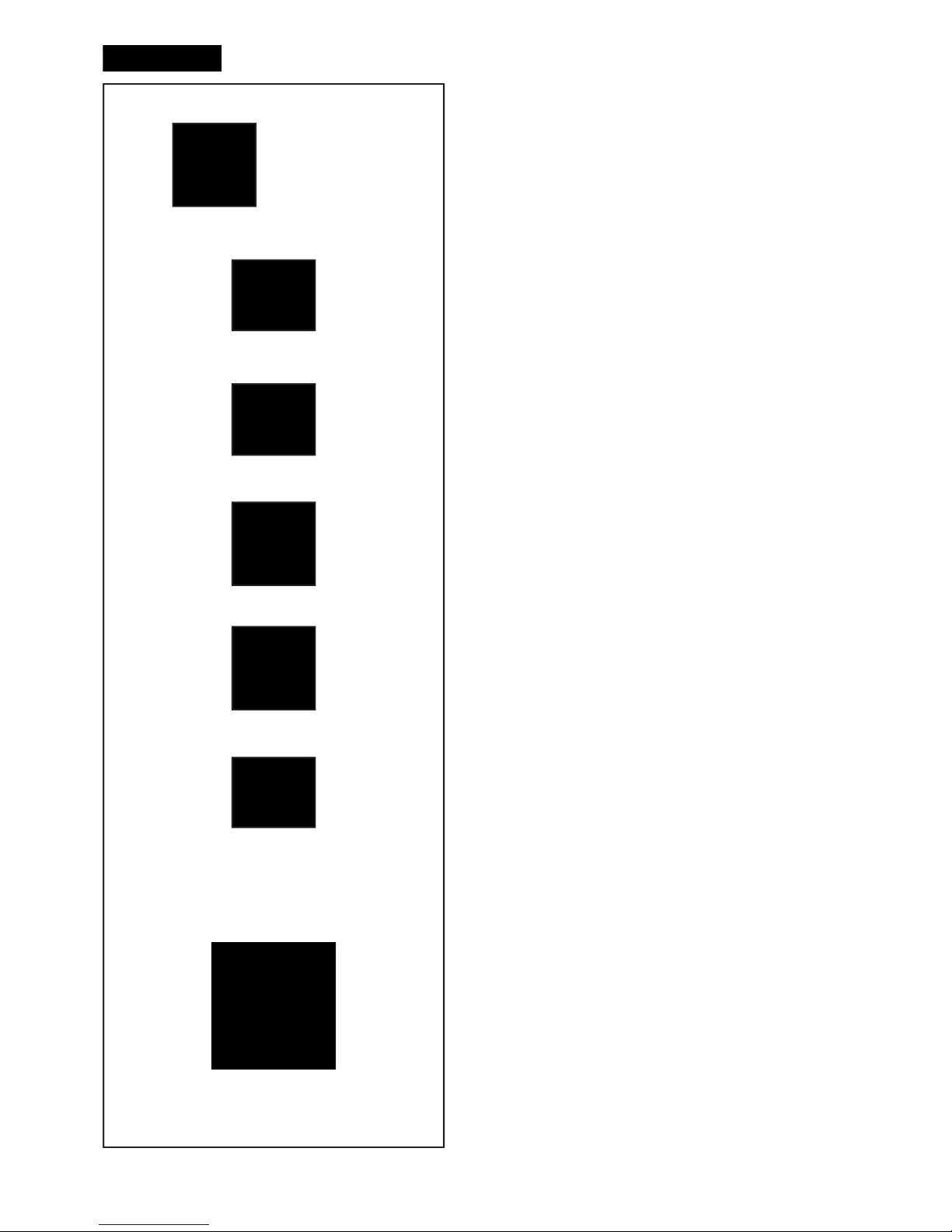
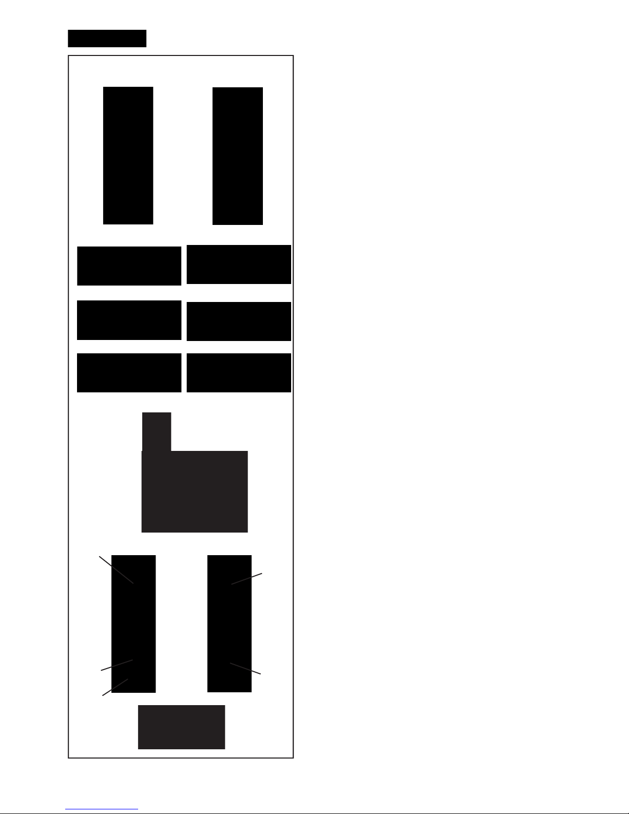
Layout
4.1 The screen
Fig. 4-3 Screen with display ! elds
1
Display fi eld
2 Information fi eld
3 Commands fi eld
The screen reads out inputs, helpful information, all
measured data and possible error codes.
Description of display fi elds
Each ! eld of the screen has a speci! c function.
1 Display fi eld
- Rim dimensions (editable).
- Balancing modes (editable).
- Unbalance value.
- List of Counters.
- C codes (User Codes).
- Help information.
2 Information fi eld
- Number of the installed program version.
- Measurements of the wheel being processed.
- Operating conditions icons.
- Error codes.
3 Commands fi eld
The pictographs illustrating basic and special
functions are located here.
Each key has an icon showing the speci! c function
it is used to retrieve.
Touch Screen
In the Touch Screen interface, in order to have a touch
response, you need to tap and release the area on the
screen with your ! nger (Fig. 4-3b).
The operator can hear a con! rmation tone, whenever
their own touch performs an action connected with
icons, buttons, text or images on the screen.
4.1.1 Screen pages / Menu
Types of Menu Fields
The Display !
eld shows the main Operating Screen
Pages:
Fig. 4-4 INTRO SCREEN
Basic screen / Main menu.
Fig. 4-5 RIM DATA ENTRY
Rim data input Screen.
Page 17

17
Layout
4.1 Bildschirm
Abb. 4-3 Bildschirm mit Anzeigezonen
1 Anzeigefeld
2 Informationsfeld
3 Steuerungsfeld
Auf dem Bildschirm werden die jeweiligen Eingabedaten,
bedienerunterstützende Informationen, alle ermittelten
Messwerte sowie Fehlermeldungen angezeigt.
Beschreibung der Anzeigezonen
Jedes Feld am Bildschirm hat eine besondere Funktion.
1 Anzeigefeld
- Felgenabmessungen (kann bearbeitet werden)
- Auswuchtarten (kann bearbeitet werden)
- Unwuchtgröße
- Liste der Zähler
- C-Codes (Benutzercodes)
- Hilfetexte.
2 Informationsfeld
- Versionsnummer des installierten Programms.
- Abmessungen des Rads, das gerade bearbeitet
wird.
- Symbol des Betriebszustands.
- Fehlercode.
3 Steuerungsfeld
Hier be! nden sich Bildzeichen, die Grundfunktionen
und Sonderfunktionen darstellen.
Auf jeder Taste ist die jeweilige Funktion, die mit der
Taste abgerufen wird, durch ein Symbol dargestellt.
Touch-Screen
Bei der Touchscreen-Schnittstelle muss man den
jeweiligen Bereich des Bildschirms mit dem Finger
berühren und dann loslassen, damit eine Reaktion auf
die Berührung erfolgt (Fig. 4-3b).
Der Bediener kann ein akustisches Signal zur
Bestätigung erhalten, sobald er mit seiner Berührung
eine Aktion ausführt, die mit Symbolen, Tasten, Text
oder Bildern auf dem Bildschirm verbunden ist.
4.1.1 Die Display-Seiten / Menu
Im Anzeigefeld sind die wichtigsten B
etriebsseiten
dargestellt:
Abb. 4-4
INTRO SCREEN
Basisbildschirm / Hauptmenü.
Abb. 4-5 RIM DATA ENTRY
Der Seite zur Eingabe der Daten.
Disposition
4.1 Écran
Fig. 4-3 Écran avec zones d’af! chage
1 Zone d’affi
chage
2 Zone d’information
3 Zone Commandes
Sur l’écran sont af! chés les paramètres, les textes
d’aide, toutes les valeurs mesurées et les messages
d’erreur.
Description des zones d’affi chage
Les zones de l’écran ont chacune un rôle spéci! que.
1 Zone d’affi chage
- Dimensions de la jante (éditables)
- Modes d’équilibrage (éditables)
- Grandeur du balourd.
- Liste des compteurs.
- Codes C (Codes Utilisateur)
- Textes d’aide.
2 Zone Informations
- Numéro de version du programme installé.
- Mesures de la roue en usinage.
- Icônes des conditions opérationnelles.
- Codes d’Erreur.
3 Zones Commandes
Les pictogrammes illustrant les fonctions de base
et les fonctions spéciales sont représentés ici.
Chaque touche possède une icône qui représente
sa fonction spéci! que.
Touch Screen
Dans l’interface d’écran tactile, il faut toucher et
retirer le doigt de la zone intéressée sur l’écran pour
avoir une réponse au toucher (Fig. 4-3b).
Un signal acoustique de con! rmation peut être
émis à chaque toucher activant une action liée à
des icônes, boutons, textes ou images à l’écran.
4.1.1 Les pages-écrans / Menu
Types de Zones Menu
L
a
zone Af! chage donne accès aux principales pages-
écrans opérationnelles:
Fig. 4-4 INTRO SCREEN
Écran de base / Menu principal.
Fig. 4-5 RIM DATA ENTRY
Page-écran du Saisie des données de la jante.
Page 18

18
4-9
4-8
4-7
4-6
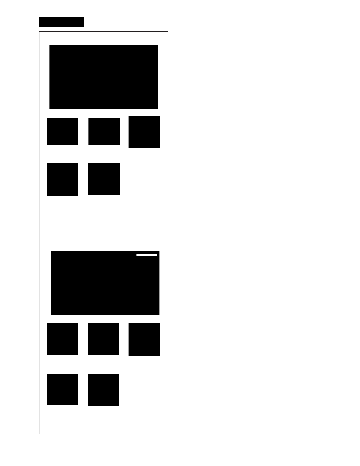
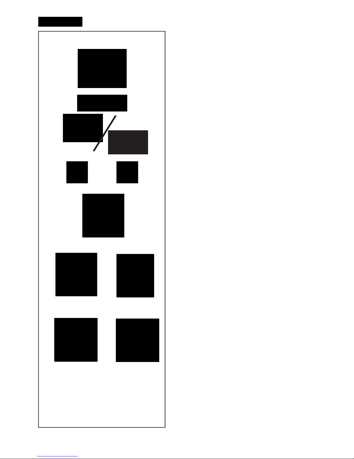
Layout
Fig. 4-6 BALANCING
Balancing Screen.
Fig. 4-7 SETTING
Settings Screen.
Fig. 4-8 COUNTERS
Counters Screen.
Fig. 4-9 OP.1
Optimisation / weight Minimisation programs Screen.
Page 19

19
Layout
Abb. 4-6 BALANCING
Bildschirm Auswuchten.
Abb. 4-7 SETTING
Einstellungen Bildschirm.
Abb. 4-8 COUNTERS
Bildschirm Zähler.
Abb. 4-9 OP.1
Bildschirm Laufruhenoptimierung/Gewichteminimierung.
Disposition
Fig. 4-6 BALANCING
Page-écran Equilibrage.
Fig. 4-7 SETTING
Page-écran Réglages.
Fig. 4-8 COUNTERS
Page-écran Compteurs.
Fig. 4-9 OP.1
Page-écran Optimisation de stabilité de marche/
Minimisation des masses.
Page 20
20
4-15
1
2
3
4
5
6
4-15b
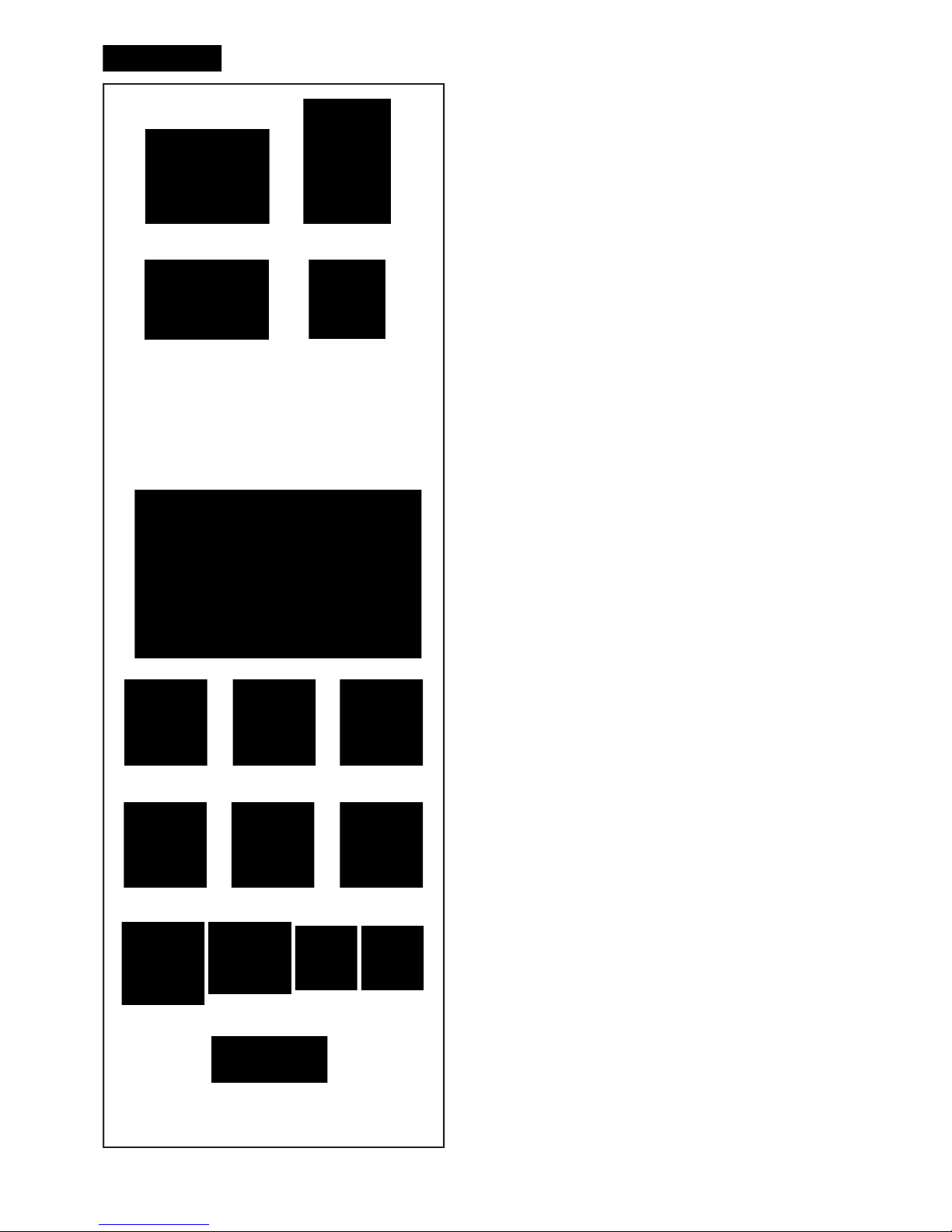
Layout
4.1.2 Basic commands
Fig. 4-15 Key pad
1 Menu keys (associated with a menu ! eld)
2 ESC key
3 HELP key
4 START key
5 STOP key (emergency stop)
6 Key to decrease
7 OK key (to con! rm)
8 Key to increase
Description of keys
1 Keys (example)
–
Ca
rry out or continue certain functions or steps of
operation.
The meaning of the menu keys is shown by associated
pictographs (symbols) on the screen.
2 ESC key
– Switch back to the previous screen (status).
– Exits the C codes procedures
– Deletes the help information and error messages.
3 HELP key
– Display useful information to explain a situation and – in
case of error codes – provide hints for remedy.
4 START key
– Start the measuring run.
Press to start balancer cycle, with the wheel guard down.
5 STOP key
– Stop a measuring run that has just been initiated and
brake the wheel.
6 OK key
– Inserts the Menu options selected previously.
Electromechanical ST
OP
Figure 4-15b
When the Electromechanical Stop Button is pressed,
the machine stops all automatic movements.
Page 21

21
Layout
4.1.2 Grundbefehle
Bild 4-15 Tastenfeld
1 Menütasten (jeweils einem Menüfeld zugeordnet)
2 ESC-Taste
3 HELP-Taste
4 START-Taste
5 STOPP-Taste
6 Taste zu verringern
7 OK-Taste
8 Taste Zu Erhöhen
Beschreibung der Tasten
1 Tasten (Beispiel)
– Fu
nktionen zur Durch- bzw. Weiterführung des jeweiligen
Arbeitsschritts wählen
Die Funktion der Menütasten wird durch zugeordnete
Piktogramme (Symbolbilder) auf dem Bildschirm angezeigt.
2 ESC-Taste
– In das vorherige Bild (Zustand) zurückschalten
– Ausstieg aus den C-Code-Verfahren.
– Löschen der Hilfetexte und Fehlermeldungen.
3 HELP-Taste
– Hilfetexte aufrufen, die die Situation erklären und bei
Meldungen Hinweise zur Fehlerabhilfe geben.
4 START-Taste
– Messlauf beginnen
Zum Starten der Raddrehung drücken, wenn die
Schutzabdeckung unten ist.
5 STOP-Taste
– Begonnenen Messlauf abbrechen und Rad abbremsen.
6 OK-Taste
– Di
e zuvor gewählte Menüoption wird eingeschaltet.
Elektromechanischer STOPP
Abbildung 4-15b
Wenn man die Taste für den elektromechanischen
Stopp drückt, hält die Maschine alle automatischen
Bewegungen an.
Disposition
4.1.2 Commandes de base
Fig. 4-15 Clavier
1
Touches de menu (attribuées resp. à une zone de
menu)
2 Touche ESC
3 Touche HELP
4 Touche START
5 Touche STOP
6 Touche à diminuer
7 Touche OK (à con! rmer)
8 Touche à augmenter
Description des touches
1 Touches (Exemple)
–
Sélection des
fonctions pour effectuer ou poursuivre le
pas de travail respectif.
La fonction des touches de menu est af! chée sur l’écran à
l’aide des pictogrammes correspondants (symboles).
2 Touche ESC
– Repasser à l’image précédente (état).
– Permet de quitter les procédures des codes C.
– Efface les textes d’aide et les messages d’erreur.
3 Touche HELP
– Appeler les textes d’aide qui expliquent la situation et
donnent en cas de messages d’erreur des conseils pour
éliminer ces erreurs.
4 Touche START
– Initialiser la lancée de mesure
Presser pour lancer la rotation de la roue, après avoir
abaissé le capot de sécurité.
5 Touche STOP
– nterrompre la lancée de mesure entamée et freiner la
roue.
6 Touche OK
– Active l’option de menu sélectionnée.
ARRET Electromécanique
Figure 4-15b
A l
a pression du bouton d’arrêt électromécanique,
la machine effectue l’arrêt de tous les mouvements
automatiques.
Page 22
22
4-9
3
2
4
10
5
6
9
87
4-10
1
Layout
4.1.2.1 Menu Buttons
Types of menu fi elds
The Menu Keys are in the Commands Field.
Therefore, depending on the position in the program,
the many Operating Screen Pages will in each case
show the Command keys needed for the functions
available.
To issue commands and select items:
— Touch the desired icons or keys on the screen.
Below are the meanings of the icons and keys
selectable on the screen.
INTRO SCREEN “Main Menu”
Fig. 4-9
1 ESC key:
- Return to MAIN MENU.
- Exit C codes.
- Clear HELP info and ERROR MESSAGES.
2 Tasto HELP: Select HELP information for the current
operations.
3 Access to: SETTINGS (press three times)
4 Access to: BALANCING
5 Access to: RIM DATA INPUT
Note:
From this screen page, simply removing the
detecting device causes an automatic switch to the
“RIM DATA ENTRY” screen page.
RIM DATA ENTRY “Rim data input”
Fig. 4-10
6 EASY ALU TOGGLE Selection
7 CAR Selection
8 MOTORCYCLE Selection
9 VAN Selection
10 Select ALU 0, 1, 2, 3, 4, 5
Page 23

23
Layout
4.1.2.1 Menü-Tasten
Arten von Menüfeldern
Im Steuerungsfeld be! nden sich die Menütasten.
Je nach Programmschritt, also auf den zahlreichen
Betriebsseiten, werden jeweils Steuertasten angezeigt,
die für die Funktionen in dem betreffenden Schritt
nötig sind.
Um Steuerbefehle zu geben und etwas auszuwählen:
— Berühren Sie die Symbole beziehungsweise
die Tasten, die Sie brauchen, direkt am Bildschirm.
In der Folge ist die Bedeutung der Symbole und Tasten
angegeben, die am Bildschirm angewählt werden
können.
INTRO SCREEN “Hauptmenü”
Abb. 4-9
1 ESC-Taste:
- Führt zum HAUPTMENÜ zurück.
- Führt zum Verlassen der C-Codes.
- Löscht HILFETEXTE und FEHLERMELDUNGEN.
2 HILFE-Taste: Hiermit werden die HILFETEXTE für
die jeweilige Operation geöffnet.
3 Zugriff auf: EINSTELLUNGEN (dreimal drücken)
4 Zugriff auf: AUSWUCHTEN
5 Zugriff auf: FELGENDATEN-EINGABE
Hinweis:
Auf dieser Bildschirmseite bewirkt das Ausfahren
des Messgeräts allein schon den automatischen
Übergang zum Bildschrim “RIM DATA ENTRY”.
RIM DATA ENTRY “Eingabe der Daten”
Abb. 4-10
6 für die Auswahl: EASY ALU TOGGLE
7 für die Auswahl: AUTO
8 für die Auswahl: MOTORRAD
9 für die Auswahl: LIEFERWAGEN
10 Wählen Sie: ALU 0, 1, 2, 3, 4, 5
Disposition
4.1.2.1 Touches de menu
Types de zone de menu
Dans
la Zone Commandes se trouvent les Touches
des Menus. Suivant la position dans le programme,
donc à l’intérieur des multiples pages-écrans
opérationnelles, il sera visualisé tour à tour les
touches de commande nécessaires aux fonctionnalités
contextuellement exécutables.
Pour effectuer les commandes et les sélections :
— Toucher directement sur l’écran les icônes ou
les touches souhaitées.
Il est indiqué ci-après la signi! cation des icônes et des
touches sélectionnables sur l’écran.
INTRO SCREEN “Menu Principal”
Fig. 4-9
1 Touche ESC:
- Retour à l’image MENU PRINCIPAL.
- Quitter les codes C.
- Effacer les textes d’AIDE et les messages d’ERREUR.
2 Touche HELP: Sélection des textes d’AIDE relatifs
à l’opérativité courante.
3 Accès à: CONFIGURATION (presser trois fois)
4 Accès à: ÉQUILIBRAGE
5 Accès à: ENTRÉE DES DONNÉES DE LA JANTE
Remarque:
La simple extraction de l’outil de mesure à partir de
cette page-écran provoque le passage automatique
à la page-écran “RIM DATA ENTRY”.
RIM DATA ENTRY “Entrée des données de la jante”
Fig. 4-10
6 Selection “EASY ALU TOGGLE”
7 Selection AUTO
8 Selection MOTO
9 Selection FOURGON
10 Sélectionnez ALU 0, 1, 2, 3, 4, 5
Page 24
24
4-10
4-11
18
23
2019
1211
13 14
17
1615
22
21
23a
Layout
Fig. 4-10
11 EDIT OFSET Selection
12 EDIT DIAMETER Selection
13 EDIT WIDTH Selection
14 MILLIMETRES / INCHES Selection.
BALANCING “Balancing Screen”
Fig. 4-11
15 START key
– Start the measuring run. Press to start balancer
cycle, with the wheel guard down.
16 STOP key
– Stop a measuring run that has just been initiated
and brake the wheel.
17 Select HIDDEN WEIGHT
18 Deselect HIDDEN WEIGHT
19 For SPOKES selection
20 Access to: OPTIMISATION-MINIMISATION
21 Restart: OPTIMISA
TION-MINIMISATION
22 Select RESOLUCION
23 To select GRAMMES / OUNCES.
23a To select STATIC / DINAMIC.
Page 25

25
Layout
Abb. 4-10
11 OFSET EDITIEREN
12 DURCHMESSER EDITIEREN
13 BREITE EDITIEREN
14 Wahl MILLIMETER / ZOLL.
BALANCING “Bildschirm Auswuchten”
Abb. 4-11
15 START-Taste
– Messlauf beginnen. Zum Starten der Raddrehung
drücken, wenn die Schutzabdeckung unten ist.
16 STOPP-Taste
– Begonnenen Messlauf abbrechen und Rad
abbremsen.
17 Wählen Sie: VERSTECKTES GEWICHT
18 für die Abwahl: VERSTECKTES GEWICHT
19
für die Auswahl der Anzahl:SPEICHENERKENNUNG
20 Zugriff auf: OPTIMIEREN-MINIMIERUNG
21 Neustart: OPTIMIEREN-MINIMIERUNG
22 Wählen Sie: AUFLÖSUNG
23
Wählen Sie GRAMMANZEIGE/UNZENANZEIGE.
23a
Wählen Sie DYNAMISCHE/STATISCHE.
Disposition
Fig. 4-10
11 Selection MODIFIER DISTANCE
12 Selection MODIFIER DIAMÈTRE
13 Selection MODIFIER LARGEUR
14 Selection MILLIMÈTRES / POUCES.
BALANCING “Page-écran Equilibrage”
Fig. 4-11
15
Touche START
– Initialiser la lancée de mesure. Presser pour lancer
la rotation de la roue, après avoir abaissé le capot
de sécurité.
16 Touche STOP
– Interrompre la lancée de mesure entamée et freiner
la roue.
17 Sélectionnez MASSE CACHÉE
18 Désélection le MASSE CACHÉE
19 Pour sélectionner le nombre de RAYONS
20 Accès à: OPTIMISATION-MINIMISA
TION
21 Redémarrez: OPTIMISATION-MINIMISATION
22 Sélectionnez SEUIL
23 Pour sélectionner GRAMMES / ONCES.
23a Pour sélectionner STATIQUE / DYNAMIQUE.
Page 26
26
24
27
25
4-12
4-13
4-14
28
29
3130
26
Layout
SETTING “Settings Screen”
Fig. 4-12
24 Select CONFIRMATION / ENTER
25 Select CONTINUES
26 Select FURTHER INFORMATION
COUNTERS “Counters Screen.”
Fig. 4-13
27 Select CONFIRMATION / CONTINUES
28 Select RESET
OP.1 “Optimisation Screen.”
Fig. 4-14
29 Select MINIMISATION
30 Select DO NOT TURN OVER TYRE.
31 Select TURN OVER TYRE.
Page 27

27
Layout
SETTING “Einstellungen Bildschirm”
Abb. 4-12
24 Wählen Sie CONFIRM / ENTER
25 Wählen Sie VORWÄRTS
26 Für die Auswahl WEITERE INFORMATIONEN
COUNTERS “Bildschirm Zähler”
Fig. 4-13
27 Wählen Sie CONFIRM / VORWÄRTS
28 Wählen Sie RÜCKSETZEN
OP.1
“Bildschirm Optimieren”
Fig. 4-14
29 Wählen Sie MINIMIERUNG
30 Für die Auswahl REIFEN NICHT WENDEN
31 Für die
Auswahl REIFEN WENDEN
Disposition
SETTING “Page-écran Réglages”
Fig. 4-12
24 Sélectionnez CONFIRMATION / ENTRER
25 Sélectionnez CONTINUE
26
Sélection PLUS D’INFOS
COUNTERS “Page-écran Compteurs”
Fig. 4-13
27 Sélectionnez CONFIRMATION / CONTINUE
28 Sélectionnez RÉINITIALISER
OP.1
“Page-écran Optimisation”
Fig. 4-14
29 Sélectionnez MINIMISATION
30 Sélection NE P
AS RETOURNER LE PNEU.
31 Selection RETOURNER LE PNEU.
Page 28
28
P3
P5
P7
P4
P6
P8
P9
P10
P11
P13
P12
P1
P2
A
A
B
C
C
Piktogramme • Pictographs • Pictogrammes
Layout
4.2 Pictographs – Symbols
Pictographs are viewed on the screen in all ! elds: In
Inf
ormation ! elds, menu ! elds, and in the display ! eld.
P1 Wheel type 1 – standard - nominal size in inches
or millimetres
P2 Wheel type 2 - motorcycle wheel
P3 Alu 0 - normal - Standard balancing mode
P4 Alu 1
P5 Alu 2, Alu 2P
P6 Alu 3, Alu 3P
P7 Alu 4
P8 Alu 5
P9 Gauge arm for distance and rim diameter
P10 Gauge arm for distance and rim diameter with
adhesive weight
P11 Display of unbalance measured and direction
indicator (red arrows or arrows head)
A No colour: greater distance from position
B
Red: rotation direction to reach the position, the
higher the number of lit segments the more the
wheel must be rotated.
P12 Correction position reached (green arrows)
C Green: compensation position reached, hold the
wheel in this position to apply the weight.
P13 Correction position for both correction planes
reached.
Page 29

29
Layout
4.2 Symbolbilder - Piktogramme
Auf dem Bildschirm werden Piktogramme in allen
Anzeigezonen dargestellt: In Informationsfeldern,
Menüfeldern und im Anzeigefeld.
P1 Radtyp 1 –Standardrad–, Nennmaße in Zoll oder
Millimetern
P2 Radtyp 2 –Rad für Motorräder
P3 Alu 0 - normal - Normale Gewichteplatzierung
P4 Alu 1
P5 Alu 2, Alu 2P
P6 Alu 3, Alu 3P
P7 Alu 4
P8 Alu 5
P9 Messarm für
Abstand und Durchmesser
P10 Messarm für Abstand und Durchmesser mit
Klebegewicht
P11 Anzeige der gemessenen Unwucht und der
Eindrehrichtung (rote Pfeile oder Pfeilspitzen)
A Nessun colore: maggiore distanza dalla posizione
B
Rosso: senso di rotazione per raggiungere la
posizione, a maggiore numero di segmenti accesi
corrisponde maggiore rotazione da compiere.
P12 Ausgleichsposition erreicht (grüne Pfeile)
C Verde: posizione di compensazione raggiunta,
trattenere la ruota in posizione per applicare il peso.
P13 Ausgleichspositionen für beide
Ebenen erreicht.
Disposition
4.2 Symboles - Pictogrammes
Sur l’écran, des pictogrammes sont af! chés dans toute
s
les zones d’af! chage: Dans les zones d’information, les
zones de menu et dans la zone d’af! chage.
P1 Type de roue 1, - roue standard-, dimensions
nominales en pouces ou en millimètres.
P2 Type de roue 2, - roue de moto
P3 Alu 0 - normal - mode d’équilibrage standard.
P4 Alu 1
P5 Alu 2, Alu 2P
P6 Alu 3, Alu 3P
P7 Alu 4
P8 Alu 5
P9 Pige de mesure pour écart et diamètre.
P10 Pige de mesure pour écart et diamètre avec
masse adhésive.
P11 L’af! chage du balourd mesuré et de la direction
d’orientation (flèches rouges ou pointe des
" èches).
A Sans couleur : écart supérieur par rapport à la position
B
Rouge : sens de rotation vers la position, la rotation
à effectuer est d’autant plus grande que le nombre
de segment allumés est plus grand.
P12 Position de correction atteinte (" èches verts).
C Vert : position de correction atteinte, bloquer la roue
dans cette position pour appliquer la masse.
P13 Positions de correction
pour tous les deux plans
de correction atteinte.
Page 30
30
P17
P16
P15
P14
P18
P19
P20 P21
P22 P23
Piktogramme • Pictographs • Pictogrammes
Layout
P14 Compensation run carried out
P15 Start measuring run by pressing the START key
or closing the wheel guard.
P16 Set the Calibration weight
P17 Provide mark on left tyre side
P18 Provide mark on right tyre side.
P19 Fit tyre on rim and infl ate to the specifi ed infl ation
pressure.
P20 Rotate rim until valve is exactly perpendicular to
and above the main shaft.
P21 Rotate wheel until valve is exactly perpendicular
to and above the main shaft.
P22 Readjust tyre on rim until the mark coincides
precisely with the valve.
P23 Readjust tyre on rim until the double mark
coincides precisely with the valve
Page 31

31
Layout
P14 Kompensationlauf durchgeführt.
P15 Messlauf starten durch Drücken der START-Taste
oder Schließen des Radschutzes.
P16 Justiergewicht befestigen
P17 Strichmarkierung links am Reifen anbringen.
P18 Strichmarkierung rechts am Reifen anbringen.
P1 9 Re i fe n au f Fe l ge m on t ie ren u nd m it
vorgeschriebenem Luftdruck füllen.
P20 Felge drehen, bis Ventil exakt senkrecht über
Hauptwelle steht.
P21 Rad drehen, bis Ventil exakt senkrecht über
Hauptwelle steht.
P22 Reifen auf Felge verdrehen, bis Markierung exakt
überVentil steht.
P23 Reifen auf Felge verdrehen, bis Doppelmarkierung
exaktüber Ventil steht.
Disposition
P14 Lancée de compensation effectuée
P15 Initialiser une lancer de mesure en appuyant sur
la touche START ou par la fermeture du carter de
roue.
P16 Fixer la masse-étalon
P17 Placer repère à gauche sur le pneu
P18 Placer repère à droite sur le pneu.
P19 Monter le pneu sur la jante et gonfl er jusqu’à la
pression prescrite.
P20 Tourner la jante jusqu’à ce que la valve se trouve
sensiblement perpendiculaire au-dessus de l’axe
principal.
P21 Tourner la roue jusqu’à ce que la valve se trouve
sensiblement perpendiculaire au-dessus de l’axe
principal.
P22 Orienter le pneu sur la jante jusqu’à ce que le repère
soitpositionné exactement au-dessus de la valve.
P23 Orienter le pneu sur la jante jusqu’à ce que le
double repère soit positionné exactement audessus de la valve.
Page 32

32
4-16
4-17
1
2
3
4
5
4-17b
4-18
Layout
4.3 Main shaft lock
Fig. 4-16 Pedal of main shaft lock
The main shaft is locked when the pedal is depressed.
This facilitates tightening or untightening of the
clamping nut and retains the wheel in the correction
position for correct ! tting of the balance weights.
Note:
This lock is designed only to facilitate orientation
of the wheel and must not be used for braking the
main shaft.
Note:
On wheel balancers equipped with the quick–acting
Power Clamp system: The pedal also controls
the Power Clamp, for clamping the wheel on the
balancer.
— Lift the pedal so as to clamp or unclamp the wheel.
— Depress the pedal to actuate the main shaft lock,
thus locating the main shaft.
4.4 Gauge arms
Fig. 4-17 Gauge arm for distance and rim diameter
1 Ga
uge arm, can be extended and hinged upwards
2 Weight holder to locate the adhesive weight both
for identi! cation of subsequent ! tting position and
for actual ! tting of the balance weight
3 Adhesive weight held in weight holder
4 Gauge head to identify rim dimensions on a
variety of rim pro! les
5 Spring-suspended applicator.
4.5 Ultrasonic detector
On the outer side of the rim the machine has an
ultrasound detector for the wheel width (outside of
rim) (Fig. 4-17b).
The sonar has a tolerance of +/- 0.5’’.
Such error does not jeopardise the accuracy of the
balancing procedure
4.6 Laser Pointer
Figura 4-18
The
machine uses
the Laser Pointer to indicate the
precise point for ! tting the adhesive weights on the
rim (F 5.8).
Note:
If the machine is set in Gauge arm mode as default, the
Laser Pointer mode can be activated by calling service.
Page 33

33
Layout
4.3 Feststellbremse
Bild 4-16 Pedal der Feststellbremse
Bei getretenem Pedal wird die Hauptwelle festgestellt.
Hierdurch wird das Anziehen bzw. Lösen der
Radspannmutter erleichtert. Außerdem kann zum
Anbringen der Ausgleichsgewichte das Rad in der
eingedrehten Ausgleichsposition gehalten werden.
Hinweis:
Diese Feststellbremse ist nur eine Positionierhilfe
und darf nicht zum Abbremsen der Hauptwelle
benutzt werden.
Hinweis:
Die Feststellbremse hat bei Auswuchtmaschinen
mit dem Schnellspannsystem Power Clamp andere
Funktionen: Außerdem hat das Pedal die Funktion
der Steuerung der Power Clamp Vorrichtung zum
Aufspannen des Rads auf die Auswuchtmaschine.
—
Das Pedal anheben, um das Rad zu spannen bzw.
zu entspannen.
— Das Pedal niedertreten, um die Feststellbremse
aus
zulösen und somit die Hauptwelle zu blockieren.
4.4 Messarm
Bild 4-17 Messarm für Abstand und Durchmesser
1
Messarm, ausziehbar und nach oben schwenk bar
2 Gewichtepratze zum Fixieren des
Klebegewichts für das Antasten der späteren
Anbringposition und beim Anbrin gen des
Ausgleichsgewichts
3 Eingelegtes Klebegewicht
4 Messtastspitze zum Abtasten der Felgenmaße
an den ver schiedenen Felgenkonturen
5 Gewichteandrückbolzen, gefedert.
4.5 Ultraschall-Messgerät
Auf der Felgenaußenseite die Maschine ist mit ei-
nem Ultraschall-Messgerät für die Radbreite (Felgenaußenseite) ausgestattet (Abb. 4-17b).
Die Toleranz des Sonars beträgt +/- 0,5’
’.
Diese toleranz hat keinen Einfl uss auf die Genauigkeit der Auswuchtung.
4.6 Laserzeiger
Bild 4-18
Mit der als Laserzeiger bezeichneten Vorrichtung zeigt
die Maschine mit einem Laserlichtpunkt die genaue
Position zur Anbringung der Klebegewichte an der
Felge (F 5.8).
Hinweis:
Wenn die Maschine in Messarm Modus eingestellt ist,
der Laser-Pointer-Modus, indem Sie den technischen
Dienst aktiviert werden ist.
Disposition
4.3 Blocage de l’arbre principal
Fig. 4-16 Pédale de blocage
L’a
rbre principal est bloqué quand la pédale est
actionnée. Cela permet de serrer ou de desserrer
l’écrou de serrage plus facilement et de maintenir la
roue en position de correction pour une mise en place
correcte des masses d’équilibrage.
Remarque:
Ce système de blocage n’est qu’une aide de
positionnement et ne doit pas être utilisé pour
arrêter la course du mandrin.
Nota Bene:
Pour les équilibreuses équipées du système de
serrage rapide Power Clamp: La pédale a également
la fonction de commander le dispositif Power Clamp,
pour la fi xation de la roue sur l’équilibreuse.
— Soulever la pédale pour serrer ou desserrer la roue.
— Appuyer sur la pédale pour actionner le système de
blocage de l’arbre principal, donc pour immobiliser
l’arbre principal.
4.4 Piges de mesure
Fig. 4-17 Pige de mesure pour écart et diamètre de
la jante
1
Pige de mesure télescopique et pivotable vers le
haut
2
Porte-masse pour tenir la masse adhésive
pour palper la position dans laquelle la masse
d’équilibrage devra être placée et pour l’y placer
3 Masse adhésive insérée
4 Tête de pige pour palper les dimensions de
jante sur les divers contours de jante.
5 Applicateur de masses, à ressort .
4.5 Détecteur à ultrasons
Sur le face externe de la jante la machine est équi-
pée d’un capteur à ultrasons pour la largeur de la
roue (face externe de la jante) (Fig. 4-17b).
La tolérance du sonar est de +/- 0.5’’.
Cette tolérance n’affecte pas l’exactitude de
l’équilibrage.
4.6 Pointeur Laser
Figura 4-18
Grâce au dispositif Laser Pointer, la machine est
en mesure d’indiquer, par un point de lumière laser,
l’endroit exact où appliquer les masses adhésives sur
la jante (F 5.8).
Remarque:
Si la machine est paramétrée en Mode Pige de mesure,
il est possible d’activer la mode Pointeur laser en
contactant le service après-vente.
Page 34

34
4-18
4-19
3
4-15
4-20
Layout
4.7 Help information
Help information explains the current action and, in
the case of an error code, provides hints for remedy.
Display help information
— Press the HELP key (Fig. 4-15, Pos. 3).
The ! rst screen with help information appears, e. g. to
the screen RIM DATA INPUT (Fig. 4-18).
— Press the HELP key once more to display the next
screen with help information.
(if present)
The second screen with help information to the screen
RIM DAT
A INPUT (Fig. 4-19) appears.
Note:
On pressing the HELP key in the last screen with help
information the display jumps to the ! rst screen again.
Quit help information
— Press the ESC key (Fig. 4-15, Pos. 2).
4.8 Electromechanical stop
Refer to Figure 4-20.
To perform an immediate stop:
• Press the Electromechanical stop button;
The electronic brake is activated to immediately stop
wheel shaft rotation, as well as any other balancer
(Lifter) automatic movement.
In the event of a stop due to an unexpected action by
the unit, reconstruct the steps taken
:
Did the operator make an error or omit to do
something?
Correct the input and continue working. No special
procedure is required.
Did the unit do something unexpected?
• Read the relevant chapters again.
• Prepare the unit for a restart:
switch off the unit
switch on the unit again.
• Carefully repeat the commands with the manual
available.
• If the unit does not function correctly,
WARNING: PREVENT ANY FURTHER USE OF THE
UNIT.
• Call the service team immediately.
Page 35

35
Layout
4.7 Hilfetexte
HIlfetexte erläutern den aktuellen Handlungsschritt und
geben bei Fehlermeldungen Hinweise zur Bearbeitung.
Hilfetext aufrufen
— HELP-Taste (Bild 4-15, Pos. 3) drücken.
Der erste HilfeText-Bildschirm erscheint, z. B. zum
Bildschirm RADDATEN EINGABE (Bild 4-18).
— HELP-Taste erneut drücken, um den folgenden
Hilfetext-Bildschirm aufzurufen.
(falls vorhanden)
Der zweite Hilfetext-Bildschirm zum Bildschirm
RADDATENEINGABE erscheint (Bild 4-19)
Hinweis
B
eim Drücken der HELP-Taste im letzten HilfetextBildschirms pringt der Hilfetext erneut zum ersten
Bildschirm.
Hilfetext verlassen
— ESC-Taste (Bild 4-15, Pos. 2) drücken.
4.8 Elektromechanischer Stopp
Siehe Abbildung 4-20.
So führen Sie einen Sofortstopp durch:
— Drücken Sie die Taste „Elektromechanischer Stopp“.
Die
elektrische Bremse wird ausgelöst und stoppt
sofort die Drehung der Radwelle sowie jede sonstige
automatische Bewegung des Auswuchtgeräts (Heber)
Wenn Sie aufgrund eines unerwarteten Verhaltens
des Geräts eine Abschaltung durchgeführt haben,
versuchen Sie, sich an die Schritte zu erinnern, die
Sie davor unternommen haben:
Hat der Bediener einen Fehler gemacht oder etwas
vergessen?
Korrigieren Sie den Fehler und fahren Sie mit
der Arbeit fort. Es müssen keine besonderen
Maßnahmen durchgeführt werden.
Hat das Gerät irgend etwas Unerwartetes getan?
—
Lesen Sie die entsprechenden Kapitel noch einmal durch.
— Bereiten Sie das Gerät auf einen Neustart vor.
Schalten Sie das Gerät ab, Schalten Sie das Gerät
wieder ein.
—
Wiederholen Sie vorsichtig die Befehle und befolgen
Sie dabei die Anweisungen in der Betriebsanleitung.
— Wenn das Gerät nicht richtig funktioniert.
WARNUNG: VERHINDERN SIE EINE WEITERE
BENUTZUNG DES GERÄTS.
• Rufen Sie sofort den Kundendienst an.
Disposition
4.7 Textes d’aide
Les textes d’aide expliquent l’opération en cours et
donnent des consignes en cas de messages d’erreur
pour pouvoir trouver un remède.
Appeler texte d’aide
— Appuyer sur la touche HELP (Fig. 4-15, Pos. 3).
La première image des textes aides est af! chée, par example
à l’image ENTREE DONNEE DE ROUE (Fig. 4-18).
— Appuyer de nouveau sur la touche HELP pour
appeler l’image suivant des textes d’aide.
(si présent)
La deuxième image des textes aides à l’image
ENT
REE DONNEE DE ROUE est af! chée (Fig. 4-19).
Remarque
En appuyant sur la touche HELP dans le dernier écran
des textes d’aide, on retournera de nouveau à l’écran
de départ des textes d’aide.
Sortir des textes d’aides
— Appuyer sur la touche ESC (Fig. 4-15, Pos. 2).
4.8 Arrêt électromécanique
Se reporter à la Figure 4-20.
Pour effectuer un arrêt immédiat :
• Ap
puyer sur le bouton d’arrêt ELECTROMECANIQUE
; le frein électronique intervient pour l’arrêt immédiat
de la rotation de l’arbre porte-roue, ainsi que tout
mouvement automatique de l'équilibreuse.
Après un arrêt causé par une action imprévue de la
machine, ré" échissez aux étapes effectuées :
Est-ce une erreur de l’opérateur ?
Corriger l’entrée et continuer. Il n’y a pas de
procédure spéciale à suivre.
Est-ce une action imprévue de la machine ?
• Relire les chapitres appropriés encore.
• Préparer la machine pour un redémarrage :
Éteindre la machine
attendre quelques secondes
rallumer la machine.
• Répéter soigneusement les instructions avec le
manuel à portée de main.
• Si le mauvais fonctionnement se répète,
ATTENTION : INTERDISEZ TOUTE UTILISATION
DE LA MACHINE.
• Appeler le SAV immédiatement.
Page 36

36
5-1.2
5-1.3
C
A
B
Operation
5.0 Operation
This chapter describes how to operate the unit in order
to balance a wheel.
The standard balancing runs will be described ! rst.
In chapter 5.4 and up special modes and functions
will be described.
Be sure to be familiar with: - possible dangers,F
1.0
- the unit, F 4.0.
5.1 Clamping a wheel
Fig. 5-1
illustrates clamping a conventional car wheel
using a clamping adaptor on the central bore.
Fig. 5-2 illustrates clamping a stud hole located car
wheel or a car wheel without centre bore using a
universal clamping adaptor.
The range and applications of the clamping means are
described in separate lea" ets.
Fig. 5-1 Clamping adaptor to clamp centre bore located
car wheels
1 Cone for car wheels
2 Rim
3 Clamping head with clamping nut (quick–clamping
nut)
5.1.1 Mounting with universal
locking device
Fig. 5-2: Universal clamping adaptor for clamping stud
hole located wheels or wheels with closed rim. This
clamping adaptor is also capable of clamping centre bore
located wheels when suitable centring rings are used.
1 Rim
2 Quick–clamping nut
3 Centring ring for centre bore located car wheels
(optional extra).
— Select the Vehicle type (F 5.5.1).
5.1.2
POWER CLAMP
Fig. 5-3
The main shaft lock pedal has two functions
A
PEDAL DOWN: Stopping rotation
PEDAL UP: POWER CLAMP lock
The pedal also controls the POWER CLAMP, for
clamping the wheel on the balancer.
B
Power Clamp with jaws fully open.
C
Power Clamp with jaws fully closed.
By changing the mode of operation it is possible to
reverse the direction of actuation of the pedal.
5-1.1
1
2
3
Page 37

37
Betrieb
5.0 Betrieb
In diesem Kapitel wird beschrieben, wie mit dem Gerät
ein Rad ausgewuchtet wird.
Zuerst werden die standardmäßigen Auswuchtvorgänge
beschrieben. In den Kapiteln ab 5.4 werden spezielle
Auswuchtungen und Funktionen beschrieben.
Stellen Sie sicher, dass Sie mit folgendem vertraut
sind: - Den möglichen F
1.0 - Dem Gerät, F
4.0.
5.1 Aufspannen eines Rades
Au f d em A
bb . 5 -1 wi rd da s A u f sp an ne n
ein e s h e rkö m mlic hen PKW- R ads mit ein er
Mittenzentriervorrichtung gezeigt.
Abb. 5-1.2 zeigt das Aufspannen eines bolzenzentrierten
Pkw-Rades bzw. eines Pkw-Rades ohne Mittenloch mit
einer Universalspannvorrichtung.
Die Auswahl und Verwendung der Spannmittel sind in
speziellen, eigenen Broschüren beschrieben.
Abb. 5-1: Mittenzentriervorrichtung für das Aufspannen
von mittenzentrierten PKW-Rädern.
1 Pkw-Aufnahmekonus
2 Felge
3 Drucktopf mit Spannmutter (Schnellspannmutter)
5.1.1 Montage mit universellem
Arretiersystem
Abb . 5-2 : Uni v ersalspannvor richtung für das
Aufspannen von PKW-Rädern mit geschlossener
Felge, die mit Bolzen zentriert sind.
Sie kann zusammen mit entsprechenden Zentrierringen
auch zum Aufspannen von mittenzentrierten PKWRädern verwendet werden.
1 Felge
2 Schnellspannmutter
3 Zentrierring für mittenzentrierte PKW-Räder
(Zubehör).
— Den Fahrzeugtyp auswählen (F 5.5.1).
5.1.2
POWER CLAMP
Bild 5-3
Das Pedal zum Feststellen der Hauptwelle hat eine
doppelte Funktion:
A
PEDAL NACH UNTEN: Blockieren der Drehung
ANGEHOBEN: POWER CLAMP Spannvorrichtung
Außerdem hat das Pedal die Funktion der Steuerung
der POWER CLAMP Vorrichtung zum Aufspannen des
Rads auf die Auswuchtmaschine.
B
Power Clamp Vorrichtung mit ganz geöffneten Backen.
C
Power Clamp Vorrichtung mit ganz geschlossenen
Backen.
Durch eine Änderung der Funktionsweise ist es möglich,
die Betätigungsrichtung des Pedals umzukehren.
Utilisation
5.0 Utilisation
Ce chapitre décrit l’utilisation de la machine pour
équilibrer une roue.
L
es étapes d’équilibrage standard sont décrites en
premier. Au chapitre 5.4 et au-delà vous trouverez la
description des modes et fonctions spéciaux.
Veuillez-vous familiariser avec : - les dangers
possibles, F
1.0 - la machine, F 4.0.
5.1
Serrage d’une roue
La Fig. 5-1 montre le serrage d’une roue de voiture
tourisme courante à l’aide d’un cône de serrage.
La Fig. 5-2 montre le serrage d’une roue de voiture tourisme
à centrage par boulons ou d’une roue de voiture sans trou
central à l’aide d’un dispositif de serrage universel.
La sél e ct ion et l’ u tilisat i on des mo y ens de
serrage sont décrites dans des manuels séparés.
Fig. 5-1 Cône de serrage pour les roues de voitures
tourisme centrées par le trou central
1 Cône pour roues de voitures tourisme
2 Jante
3 Tête de serrage avec écrou de serrage (écrou à
serrage rapide)
5.1.1 Montage avec dispositif de
blocage universel
Fig. 5-2: Moyen de serrage universel pour les roues
à
jante fermée ou les roues centrées par des boulons.
Ce moyen se prête également pour les roues centrées
par trou central si les anneaux de centrage appropriés
(accessoires) sont utilisés.
1 Jante
2 Ecrou à serrage rapide
3 Anneau de centrage pour roues de voitures
tourisme à centrage central (option).
— Sélectionner le type de véhicule (F
5.5.1).
5.1.2
POWER CLAMP
Fig. 5-3
La pédale de blocage de l’arbre principal a une double
fonction:
A
PEDAL APPUYÉ: Blocage de la rotation
PEDAL SOULEVÉ: Blocage POWER CLAMP
La pédale a également la fonction de commander le
dispositif POWER CLAMP, pour la ! xation de la roue
sur l’équilibreuse.
B
Dispositif Power Clamp avec mâchoires entièrement
ouvertes.
C
Dispositif Power Clamp avec mâchoires entièrement
fermées.
Par changement du mode de fonctionnement, il est
possible de renverser le sens d’actionnement de la pédale.
Page 38

38
5-1.4
5-1.5
5-1.6
Operation
5.1.3 Clamping / unclamping the wheel
The electric controller is so designed that after turning
on the mains switch the clamping jaws remain in
their instantaneous position and any change must be
effected intentionally by actuating the pedal.
5.1.3.1 Clamping the wheel
Note:
Before clamping the wheel make sure the contact
surfaces on wheel adaptor and rim are free from
dirt and grease.
• Move the clamping jaws to unclamped position
(Fig. 5-1.4).
• Slide the centring cone or centring ring (chosen
function of centre bore diameter of the wheel) on
the main shaft (Fig. 5-1.5).
• Position the wheel to be clamped on the centring
cone or ring, hold approximately in vertical position
with the left hand and slide the clamping sleeve
and clamping means (clamping head, pressure ring,
or fl ange plate) on the chuck (Fig. 5-1.6).
• Press the clamping sleeve and clamping means
fi rmly against the wheel and lift the pedal (Fig.
5-1.6).
•
Check for proper clamping prior to the measuring run.
Notes
If the pedal is actuated once again during the clamping
process, clamping is interrupted and the clamping jaws
return to unclamped position.
After every clamping operation the screen RIM DATA
INPUT comes up automatically.
With every wheel balancer “P” measurement can be
started only when the wheel is clamped and the wheel
guard closed.
5.1.3.2 Unclamping the wheel
Note:
While the
jaws unclamp, hold the wheel so that it
will not tilt when unclamped.
• Lift the pedal (Fig. 5-1.6).
• Remove the clamping sleeve from the chuck.
• Remove the wheel.
Page 39

39
Betrieb
5.1.3 Rad spannen / abspannen
Die elektrische Steuerung ist so ausgelegt, dass nach
dem Einschalten des Netzschalters die Spannklauen
in der momentanen Stellung verbleiben und eine
Veränderung durch Betätigung des Pedals gezielt
eingeleitet werden muss.
5.1.3.1 Rad aufspannen
Hinweis :
Vor dem Aufspannen des Rades darauf achten,
dass die Anlagefl äche des Grundkörpers und die
Anlagefl äche der Felge fett– und schmutzfrei sind.
• Die Spannklauen in Stellung entspannt stellen
(Bild 5-1.4).
• Den entsprechend dem Mittenlochdurchmesser des
Rades gewählten Zentrierkonus oder Zentrierring
auf die Hauptwelle aufschieben (Bild 5-1.5).
• Das zu spannende Rad auf den Zentrierkonus
oder Zentrierring aufsetzen, mit der linken Hand
etwasenkrecht halten und die Spannhülse mit dem
gewählten Spannmittel (Drucktopf, Druckring oder
Wechselfl ansch) auf das Spannfutter aufschieben
(Bild 5-1.6).
• Die Spannhülse mit dem gewählten Spannmittel
fest gegen das Rad drücken und das Pedal
anheben(Bild 5-1.6).
• Vor dem Messlauf den Sitz des Rades auf der
Spannvorrichtung prüfen.
Hinweise
Wird das Pedal während des Spannvorgangs nochmals
betätigt, wird das Spannen abgebrochen und die
Spannklauen gehen in die Stellung entspannt zurück.
Bei den Bildschirmmaschinen “P” wird nach dem
Spannen automatisch in den Bildschirm RADDATEN–
EINGABE für Raddaten–Eingabe geschaltet.
Bei Maschinen “P” das Messlauf kann nur gestartet
werden, wenn das Rad gespannt und der Radschutz
geschlossen ist.
5.1.3.2 Rad abspannen
Hinweis :
Während die
Spannklauen entspannen, das Rad
etwas festhalten, damit es nicht umkippt, wenn sich
die Spannung löst.
• Das Pedal anheben (Bild. 5-1.6).
• Die Spannhülse vom Spannfutter abziehen.
• Das Rad abnehmen.
Utilisation
5.1.3 Serrage / desserrage de roue
La commande électrique est conçue telle qu’après
la mise en
circuit de l’interrupteur secteur les mors
de serrage restent dans leur position instantanée et
que tout changement doit être effectué exprès par un
actionnement de la pédale.
5.1.3.1 Serrage de roue
Remarque :
Avant le serrage d’une roue, veiller à ce que les
surfaces de contact du corps de base du moyen de
serrage et de la jante soient exemptes de graisse
et propres.
• Positionner les mors de serrage en position
desserrée (Fig. 5-1.4).
• Positionner le cône ou l’anneau de centrage (choisi
fonction du diamètre du trou central de la roue) sur
l’arbre principal (Fig. 5-1.5).
•
Placer la roue à serrer sur le cône ou l’anneau de
serrage, la maintenir, avec la main gauche, à peu
près en position verticale et pousser la douille et
le moyen de serrage (tête de serrage, anneau de
serrage ou fl asque d’échange) sur le mandrin (Fig.
5-1.6).
• Presser la douille et le moyen de serrage fortement
contre la roue et soulever la pédale (Fig. 5-1.6).
• Contrôler, avant la lancée de mesure, si la roue est
bien serrée.
Notes:
Si la pédale est actionnée encore une fois pendant le
serrage, le serrage est interrompu et les mors rentrent
en position desserrée.
En cette équilibreuses l’image ENTREE DONNEES DE
ROUE se présente automatiquement après chaque serrage.
Pour toutes les équilibreuses “P”, la mesure est lancée
seulement si la roue est serrée et que le carter de roue
est fermé.
5.1.3.2 Desserrage de roue
Remarque :
Pendant le desserrage des mors, retenir la roue
pour qu’elle ne tombe pas lors du desserrage.
• Soulever la pédale (Fig. 5-1.6).
• Prendre la douille de serrage du mandrin.
• Enlever la roue.
Page 40

40
5-2
4-4
4-5
I
O
1
Operation
5.2 Preparation
• The operator should be familiar with the warnings
and cautions.
• The operator should be quali! ed to work with the
unit.
• Always ensure that the wheel guard is lifted and the
gauge arm is in its home position (far left position)
when the unit has been switched off.
5.2.1 Power up
• Do not keep any key pressed down during power
up
.
Refer to Fig. 5-2.
• Insert the power cable plug in the mains socket “1”.
• Set the switch on the socket to the “I” position.
Note: If the unit beeps and does not proceed or
if an error code is shown, F 7.0.
The unit will beep and perform a self-test now.
The displays and the weight position indicators relating
to the current weight mode will be shown (default).
After switch on the ! rst screen page shown is RIM
DATA ENTRY (Fig. 4-4).
The unit is now ready for commands.
Note If in the INTRO SCREEN page (Fig.
4-5), you can switch directly to the RIM
DATA ENTRY screen page by simply
removing the detecting device for wheel
data acquisition.
5.2.2 Status at switching on
The electronic unit is factory-adjusted to the following
m
od
es of operation, which are available after switching
on:
– vehicle type 1 (car wheel with nominal dimensions
in inches, width 6.5” and diameter 15.0”)
– entry of rim data in inches
– display of amount of unbalance in 5-g increments
– suppression of minor unbalance readings (limit
set to 3.5 g)
– automatic braking of wheel when guard is
opened during the measuring run
– compensation of adaptor unbalance switched
off
– Starting the mesuring run by closing the wheel guard.
Page 41

41
Betrieb
5.2 Vorbereitung
• Der Bediener muss mit den Warnhinweisen und
Vorsichtsmaßnahmen vertraut sein.
• Der Bediener muss für die Arbeit mit dem Gerät
quali! ziert sein.
• Stellen Sie immer sicher, dass die Radabdeckung
ange h oben i s t und d e r Mess a rm in d er
Ausgangsstel lung ist, wenn die Mas chine
ausgeschaltet ist.
5.2.1 Anschalten
• Halten Sie beim Einschalten keine Taste gedrückt!
Siehe Abbildung 5-2.
• Stecken Sie den Stecker des Netzkabels in die
Stromversorgungsdose.
• Sc
halten Sie den Schalter, der sich in der Nähe des
Steckers befi ndet, auf “I”.
Hinweis: Schauen Sie in Kapitel 7.0 nach, wenn
das Gerät piept oder stecken bleibt oder
wenn ein Fehlercode angezeigt wird.
Das Gerät piept und führt einen Selbsttest durch.
Daraufhin werden die Displays und die Anzeigen
für die Gewichtspositionen je nach dem aktuellen
Gewichtsmodus (Default) angezeigt.
Nach dem E insch a lten wird als E r stes die
Bildschirmseite RIM DATA ENTRY eingeblendet
(Abb. 4-4).
Das Gerät ist nun bereit zur Eingabe.
Hinweis Falls man sich auf der Bildschirmseite
INTRO SCREEN befi ndet (Abb. 4-5),
kann man direkt auf RIM DATA ENTRY
übergehen, indem man einfach das
Messgerät zur Erfassung der Raddaten
ausfährt.
5.2.2 Einschaltzustand
Die Elektronik ist werkseitig so programmiert, dass
n
ac
h dem Einschalten die folgenden Funktionsweisen
gegeben sind:
– Fahrzeugtyp 1 (Pkw-Rad mit Zoll-Nennmaßen,
Breite 6,5” und Durchmesser 15,0”) gesetzt
– Eingabe der Felgenmaße in Zoll (inch)
– Unwuchtgrößenanzeige in 5-Gramm-Stufen
– Un te rdrück u ng (Grenz w ert 3,5 G ra mm)
eingeschaltet
– Zwangsweise Abbremsung des Rades bei Öffnen
des Radschutzes während eines Messlaufs
– Kompensation der Spannvorrichtungsunwucht
ausgeschaltet
– Starten eines Messlaufs durch Schließen des
Radschutzes.
Utilisation
5.2 Préparation
• L’opé r at eur do i t s e fami l i arise r a vec le s
avertissements et les mesures de sécurité.
• L’opérateur
doit être formé pour travailler avec la
machine.
• S’assurer toujours que la protection de la roue est
soulevée et que le bras de mesure est en position
de repos (placé à l’extrême gauche) quand l’unité
est éteinte.
5.2.1 Allumage
• Ne pas toucher la machine pendant l'allumage!
Se reporter à la Fig. 5-2.
• Greffer l'épine du câble d'alimentation dans la prise
de réseau "1”.
• Activer l'interrupteur qui se trouve en proximité de
l'épine en le portant en position "I”.
Remarque : Si la machine émet un bip sonore et
s’arrête ou si un code erreur est indiqué,
F 7.0.
La machine émet un bip sonore et effectue une vérifi cation.
Elle indiquera les affi cheurs et les indicateurs des
positions des masses en fonction du mode Masse
courant (par défaut).
La première page-écran qui apparaît à la mise sous
tension est RIM DATA ENTRY (Fig. 4-4).
A ce stade, la machine est prête à recevoir des commandes.
Remarque
Si on se trouve dans la page-écran
INTRO SCREEN (Fig. 4-5), on pourra
passer directement à la page-écran RIM
DATA ENTRY en extrayant l’outil de mesure
pour l’acquisition des données roues.
5.2.2 Etat à la mise en circuit
L’unité électronique est programmée par le fabricant de
façon à ce que les modes de fonctionnement suivants
soient disponibles après la mise en circuit:
– type de véhicule 1 (roue de voiture tourisme
ave c dimensions nom inales en pouces,
largeur 6,5” et diamètre 15,0”)
– entrée des dimensions de jante en pouces (inch)
– affi chage du balourd en échelons de 5 g
– suppression de l’affi chage de faibles balourds
(limite réglée à 3,5 g)
– freinage automatique de la roue si on ouvre le
carter pendant la lancée de mesure
– compensation du balourd du moyen de serrage
débranché
– Démarage de la mesure par fermeture du carter.
Page 42

42
4-10
4-11
22
14
Operation
5.2.3 Settings
After switching on the unit, a default weight mode is
shown. If the unit then shows another weight mode,
F 5.3 and 5.4.
The unit of measurement indicated at power up is
inches, but the setting selected before switching off
for grams / ounces remains.
5.2.3.1 Changing the Dimensions Unit
Default diameter and width unit setting: inches.
•
Press the “mm” or “inch” icon (14, Fig. 4-10).
The measuring unit changes to the possible alternative.
5.2.3.2 Changing the Weight Unit
Default weight unit setting: grams.
Proceed as follows
to change the weight unit, whether
you have already spun the wheel or not.
• Press the key "g” or “oz” icon (22, Fig. 4-11).
The measuring unit changes to the possible alternative.
5.2.4 Shutting down
Always shut down properly when work is complete:
• Remove the and hub nut and the wheel from the
balancer.
• Remove the cones from the stub shaft. Check the
surfaces (internal and external) of the cones for
damage. The condition of the cone is very important
for a good balance quality.
• Store the cones and the hub nut in the correct place.
• Check the thread of the hub nut and stub shaft.
• Clean all threads and surfaces with a dry, soft cloth.
• Unplug the mains cable from the power outlet.
• Check the power cable for damage or wear.
• Tidy up the storage areas.
• Clean the display and input panel with a soft, dry
cloth.
• Check that the balancer is only resting on its own
three feet. Remove old wheel weights taken off and
any other materials from under the balancer.
Page 43

43
Betrieb
5.2.3 Einstellungen
Nach dem Eins c h al te n de s Ger ä ts wir d ein
standardmäßiger Gewichtsmodus angezeigt. Sehen
Sie in Kapitel 5.3 und 5.4 nach, wenn das Gerät einen
anderen Gewichtsmodus anzeigt.
Die standardmäßige Maßeinheit beim Einschalten des
G
eräts ist Zoll; es bleibt aber die Einstellung in Gramm
oder Unzen, die vor dem Abschalten vorgenommen
wurde.
5.2.3.1 Umschaltung Größeneinheit
Geben Sie am Symbol „mm“ bzw
. „inch”
ein (14,
Abb. 4-10).
• Drücken Sie die “mm/inch” Taste” (F6, Abb. 4-10).
Die Maßeinheit wird auf die jeweils andere umgeschaltet.
5.2.3.2 Umschaltung der Gewichtseinheit
Standardeinstellung der Gewichte: Gramm.
Mit dieser Methode können Sie die Maßeinheit des
Gewichts ändern – sowohl vor oder nach dem Messlauf.
• Geben Sie am Symbol „g“ bzw. „oz” ein (22, Abb. 4-11).
Die Maßeinheit wird auf die jeweils andere umgeschaltet.
5.2.4 Abschalten
Schalten Sie das Gerät am Ende einer Arbeitsschicht
immer ordnungsgemäß ab:
• Nehmen Sie das Rad und die Spannmutter von
dem Auswuchtgerät.
• Nehmen
Sie die Konusse von der Flanschwelle.
Überprüfen Sie die Oberflächen der Konusse
(innen und außen) auf Beschädigungen. Die
Unversehrtheit des Konus ist sehr wichtig für eine
gute Auswuchtqualität.
•
Bewahren Sie die Konusse und die Schnellspannmutter
an dem ordnungsgemäßen Platz auf.
• Überprüfen Sie das Gewinde der Schnellspannmutter
und der Flanschwelle.
• Reinigen Sie alle Gewinde mit einem trockenen und
weichen Lappen.
• Ziehen Sie das Stromversorgungskabel aus der
Steckdose.
• Überprüfen Sie das Stromversorgungskabel auf
Beschädigungen und Verschleiß.
• Räumen Sie die Aufbewahrungsbereiche auf.
• Reinigen Sie das Display und das Eingabefeld mit
einem trockenen und weichen Lappen.
•
Stellen Sie sicher, dass das Auswuchtgerät nur auf seinen
drei Füßen steht. Sammeln Sie die alten Gewichte, die von
den Rädern entfernt wurden, und alles sonstige Material
auf, das unter das Auswuchtgerät geraten könnte.
Utilisation
5.2.3 Réglages
Après l’allumage de l’unité un type de roue est af! ché
par défaut. Si l’unité montre ensuite un type de roue
différent, F 5.3 et 5.4.
Les paramètres par défaut de la machine sont les
grammes et les pouces, mais le réglage sélectionné
avant d’éteindre la machine, pour les grammes / once,
reste.
5.2.3.1 Commutation Unités dimensionnelles
de défaut diamètre et largeur en : pouces.
• Presser l’icône “mm” ou “inch” (14 Fig. 4-10).
L’unité de mesure change, soit le pouce, soit le mm.
5.2.3.2 Commutation Unité de Poids
Sélection poids de défaut en : grammes.
Sélectionner cette méthode pour changer l’unité de
poids, indif
féremment avant ou après avoir exécuté
un lancement.
• Presser l’icône “g” ou “
o
z” (22, Fig. 4-11).
L’unité de mesure change, soit le gramme, soit l’once.
5.2.4 Arrêt
À la ! n du travail compléter toujours les opérations de
façon convenable:
• Retirer la roue et la manivelle de serrage de
l’équilibreuse.
• Retirer les cônes. Vérifier que les surfaces
des cônes (internes et externes) ne sont pas
endommagées. Le cône est très important pour un
équilibrage de bonne qualité.
•
Replacer les cônes et la bague à leur juste emplacement.
• Véri! er le taraudage de la bague de blocage et de
l’embout d’arbre.
• Nettoyer tous les ! lets et surfaces avec un chiffon
doux et sec.
• Débrancher la ! che d’alimentation électrique de la
prise de courant.
•
Véri! er que le câble secteur n’est pas endommagé ou usé.
• Ranger les bacs porte-plombs.
• Nettoyez le panneau d’af! chage et d’entrée avec
un chiffon sec.
• Véri! er si l’équilibreuse prend bien appui sur ses
trois pieds. Débarrasser les roues des masses
désormais inutilisables et ramasser tout éventuel
matériau qui pourrait ! nir sous l’équilibreuse.
Page 44

44
4-11
STATIC
Operation
5.3 Weights positioning Modes
The unit always has a weight mode automatically
selected, refer to the display.
The weight mode currently selected is shown by the
illuminated indicator(s).
NORMAL
Used for steel rims.
ALU mode
Used for light alloy rims or where one or more stickon weights are to be used.
The stick-on weight(s) must be applied by hand.
Hidden Weight Mode
Used for light alloy rims or for wheels that are
dif! cult to balance.
The stick-on weight(s) must be applied with the
gauge arm. This guarantees more accurate weight
positioning compared to applying the stick-on
weight(s) by hand.
Note: If the stick-on weight must be hidden
behind two spokes, select the Split Weight
Mode before applying the weight in the
right plane
(F 5.9).
STATIC
(Figure
4-11)
Retrieve the function with key (Fig. 4-11
).
Used for small wheels that are not balanced
dynamically, e.g.: small moped wheels.
No “left” or “right” weight is calculated.
— Mount the wheel according to paragraph 5.1 and
select the corrected reading positions of the gauge
head (F 5.4).
Page 45

45
Betrieb
5.3 Gewichteplatzierung Modus
Das Ger ät z eig t im m er aut o mat i sch ein en
Gewichtsmodus an.
D
er ausgewählte Gewichtsmodus wird durch den
entsprechenden Leuchtanzeiger angezeigt.
NORMAL
Wird für Stahlfelgen benutzt.
“ALU-Modes”
Wird für Leichtmetallfelgen oder in Situationen
benutzt, bei denen ein oder mehrere Klebegewichte
benutzt werden sollen. Die Klebegewichte werden
mit der Hand angebracht
“Hidden Weight Modes” (HWM)
Wird bei Leichtmetallfelgen und bei Rädern, die
schwer auszuwuchten sind, benutzt.
Die Klebegewichte werden mit dem Messarm
angebracht. Dies gewährleistet eine genauere
Positionierung des Klebegewichts im Vergleich zur
Anbringung mit der Hand.
Hinweis: Wenn ein Klebegewicht hinter zwei
Speichen versteckt werden muss,
müssen Sie “Split Weight Mode” wählen,
bevor Sie das Gewicht in der rechten
Ebene anbringen (F 5.9).
“STATIC”
(Abb. 4-11)
Diese Funktion wird mit der Taste (Abb. 4-11)
abgerufen.
Wird bei kleinen Rädern benutzt, die nicht
dynamisch ausgewuchtet werden, z. B. kleine
Motorradräder.
Es wird kein „linkes” oder „rechtes” Gewicht
berechnet.
— Montieren Sie das Rad nach der Anleitung im
Abschnitt 5.1 und wählen die korrekten Antast
positionen (F 5.4).
Utilisation
5.3 Modes de fi xation des masses
La machine a toujours un type de mode d’équilibrage
sélectionné à l’af!
chage.
Le mode sélectionné est indiqué par le(s) leed(s)
allumées correspondant à la position des masses.
NORMAL
Utilisé pour les jantes en acier.
Modes ALU
Utilisés pour les jantes en métal léger ou lorsqu’une
utilisation d’un ou plusieurs masses adhésifs est
nécessaire.
Le(s) masses adhésif(s) doit/doivent être posé(s)
manuellement.
Modes de Masses Cachés
Utilisés pour les jantes en métal léger, ou pour les
roues dif! ciles à équilibrer.
Le(s) masses adhésif(s) doit/doivent être placé(s)
avec le bras de jauge qui assure un placement
des masses plus précis en comparaison avec le
placement manuel.
Remarque : Si la masses adhésive du plan
droit doit être caché derrière les batons,
sélectionner le Mode Masses Divisé
avant de placer le masses dans le plan
droit (F 5.9).
STATIQUE (“STATIC”)
(Fig. 4-11)
Cette fonction est rappelée avec la touche illustré
dans l’illustration 4-11.
Utilisé pour les roues de moins de 3‘’ qui ne sont
pas dynamiquement équilibrées, par ex. les roues
de moto de petite cylindrée. Placer une masse
seulement sur la ligne médiane de la roue. Les
masses «gauche» et «droite» ne sont pas calculés.
— Installer la roue selon le paragraphe 5.1 et
sélectionner las positions de palpage correctes des
pige de mesure (F 5.4).
Page 46

46
5-5
1
1
2
3
X
Operation
5.4 Dimensional detections
The dimensions of the balance weights are detected,
on the basis
of real data, or rather on measurements
taken directly by the Gauges if the automatic Easy
Alu function is used (F 5.6). If the data is entered
manually (F 5.5) these ! gures are calculated on the
basis of nominal values by adding or subtracting the
average correction values.
5.4.1 Calibration Gauge
The internal Calibration Gauge for distance and
diameter
is used
to enter the distance between the
machine and the left correction plane, as well as the
nominal rim diameter/correction diameter.
The internal Calibration Gauge allows the effective
correction planes and diameters of the adhesive
weights ! xed to the bead seats and hidden weights to
be calculated exactly.
Fig. 5-5 Internal Calibration Gauge for rim distance
and diameter.
1 Internal Calibration with gauge head
2 Gauge head
3 Reference edge for distance reading X
– Using the distance and diameter measurement
Internal Gauge (1, Figure 5-5) the distance
between the machine and the left correction plane
is detected and obtained automatically as well as
the diameter of the rim.
Application:
— Extract and rest the Gauge Head on the rim and
keep it in position until an audible signal is heard.
— Move the Gauge to the idle position.
When the measurements have been completed and
the idle position is reached, the rim dimensions are
shown on the screen in the indicator ! elds between
the relative arrows. A selection of weight positions (Alu
type) is also shown.
If the Gauge doesn’t function correctly or if the
correction positions on the wheel on the machine are
outside the calibration reading ! eld, it is still possible
to set the dimensions from the menu and proceed in
manual mode (F 5.5).
Page 47

47
Betrieb
5.4 dimensional Erkennungen
Die Abmessungen der Ausgleichsgewichte werden
auf der Basis von realen Daten bestimmt, d.h. Daten,
die direkt von den Abtastarmen erfasst wurden, falls
die Funktion Easy-Alu aktiviert ist (F 5.6). Im Falle
einer manuellen Eingabe der Daten werden die
Abmessungen aufgrund der Nennwerte berechnet (F
5.5), indem die durchschnittlichen Ausgleichswerte
abgezogen bzw. hinzugefügt werden.
5.4.1 Der Abtastarm
Der interne Abtastarm für Abstand und Durchmesser
w
ir
d verwendet, um das Abstandsmaß zwischen
Maschine und linker Ausgleichsebene sowie den
Felgennenn- bzw. Ausgleichsdurchmesser abzutasten.
Der Abtastarm ermöglicht es, die Ausgleichsebenen
und die tatsächlichen Ausgleichsdurchmesser der
Klebegewichte am Felgenrand und der versteckten
Gewichte zu bestimmen.
Abb. 5-5 Interner Abtastarm für die Messung des
Abstands und des Felgendurchmessers.
1 Messarm mit Tastkopf
2 Tastkopf
3 Ablesekante für Abstandsmaß X
– Mit dem Abtastarm für die Messung von Abstand
und Durchmesser (1, Abb. 5-5) werden der
Abstand zwischen linker Ausgleichsebene und
Maschine und gleichzeitig der Felgendurchmesser
automatisch abgetastet und erfasst.
Anwendung:
— Den Tastkopf herausziehen und an die Felge legen.
In dieser Position lassen, bis ein akustisches Signal
ertönt.
— Den Abtastarm in die Ruheposition bringen.
Sobald die Messung beendet und der Arm wieder in
Ruheposition ist, werden die Felgenabmessungen auf
dem Bildschirm in den entsprechenden Anzeigefeldern
und zwischen den entsprechenden Pfeilen angezeigt.
Außerdem wird eine Auswahl für die Positionierung der
Gewichte aufgeführt.
Ist jedoch der Abtastarm defekt oder wird ein Rad
bearbeitet, dessen Ausgleichspositionen außerhalb
des Abtastbereichs des Messarmes liegen, können die
Abmessungen auch über das Menü eingegeben und
das die Eingriffe manuell fortgeführt werden (F 5.5).
Utilisation
5.4 Détections des dimensions
Les valeurs des masses de correction sont obtenues
d’après
les données
réelles, autrement dit, mesurées
directement par les piges en cas d’utilisation de
la fonction automatique Easy Alu (F 5.6). En cas
de saisie manuelle des données (F 5.5), elles
sont calculées d’après les valeurs nominales par
soustraction ou addition des valeurs de correction
moyennes.
5.4.1 Pige de Misure
La pige de mesure interne pour l’écart et le diamètre
de
jante permet
de palper l’écart entre la machine et
le plan de correction gauche, ainsi que le diamètre
nominal de jante ou le diamètre de correction.
La pige de mesure interne permet de saisir précisément
les plans de correction et les diamètres de correction
effectifs pour les masses adhésives ! xées sur les
assises du pneu et pour les masses cachées.
Fig. 5-5 Pige de mesure interne pour écart et
diamètre de jante.
1 Pige de mesure interne avec tête de pige
2 Tête de pige
3 Rebord de lecture pour valeur d’écart X
– La pige de mesure interne de l’écart et du diamètre
(1, Fig. 5-5) permet de mesurer et de saisir
automatiquement l’écart entre le plan de correction
gauche et la machine ainsi que le diamètre de la
jante.
Application:
— Extraire et poser la tête de pige sur la jante et
la maintenir dans cette position jusqu'au signal
acoustique.
— Remettre la pige en position de repos.
Dès que la pige est replacée en position de repos
après la mesure, les dimensions de jante s’af! chent à
l’écran dans des zones de données entre les " èches de
mesure correspondantes. Par ailleurs, une sélection de
positionnement des masses (type d’Alu) est présentée.
Si toutefois le pige de mesure est défectueuse ou si
on doit traiter une roue dont les positions de correction
sont en dehors des possibilités de palpage, il est
toujours possible de saisir les dimensions de la jante
depuis le menu et de continuer en mode manuel (F
5.5).
Page 48

48
d
a
c
b
e
f
1 2
1
2
1 2
A
B
5-6
5-7
Operation
5.4.2 Gauge head application on
various Wheel types
In order to be able to determine unbalance in a single
m
easuring run, the rim dimensions have to be
entered correctly. Therefore proceed with utmost
care and as is shown in the Figures when applying
the gauge head on the rim in the desired weight ! tting
position. Incorrect application will result in deviations
of measured values and consequently inaccurate
results of the measuring run.
Fig. 5-6 a to 5-6 f show correct application (with and
without adhesive weight) of the gauge head on various
rims and for various weight ! tting positions.
Fig. 5-6 a Standard wheel – Steel rim
1 Gauge head
2 Rim
Fig. 5-6 b Standard wheel – Alloy rim
Fig. 5-6 c Light-truck wheel – Steel rim
Fig. 5-6 d Light-truck wheel – 15° taper steel rim
Fig. 5-6 e Alloy wheel - Rim without a housing for
clip-on weights
Fig. 5-6 f Alloy wheel – Adhesive weights
1 Left correction plane, ! rst application position
2 Right correction plane, second application position.
Note: Further to measurements for ALU P, the display
does not show rim width value since it is not important
for balancing. In these cases symbol “- -” is displayed.
5.4.2.1 Weights application with feeler arm or
with laser pointer
The reading point on the rim is given by the upper rig
ht
end of the feeler (A and B, Fig.5.7).
Based on the weights application system enabled (arm
or laser), the feeler must be positioned in different
positions (A for arm, B for laser) in order to achieve
the identical axial positioning of the adhesive weight
on the rim.
ARM APPLICATION
(1, Fig. 5-7) (Laser Pointer disabled)
Weights application at the top with the arm head. The
weight will be placed on the left in relation to the feeler
contact point (A) on the rim.
LASER POINTER APPLICATION
(2, Fig. 5-7) (Laser Pointer enabled)
Weights application at about 5 o’clock, on the right of
the laser point. The weight will be placed on the right
in relation to the feeler contact point (B) on the rim.
Page 49

49
Betrieb
5.4.2 Antastpositionen an den
verschiedenen Radtypen
Um die Unwucht möglichst in nur einem Messlauf zu
ermitteln, ist es notwendig, die Felgenabmessungen
korrekt einzugeben. Deshalb das Antasten mit dem
Tastkopf an der Felgenkontur bzw. an der gewählten
Gewichteplatzierung sorgfältig und entsprechend
den Abbildungen vornehmen. Maßabweichungen
füh ren zu Messwertabweich ungen und so zu
ungenauem Auswuchtergebnis.
Die Abbildung 5-6 a bis 5-6 f zeigen die korrekten
Antastpositionen (ohne bzw. mit Klebegewicht) der
Messtastspitze an den verschiedenen Felgen und für
verschiedene Gewichteplatzierungen.
Abb. 5-6 a Standardrad – Stahlfelge
1 Messtastspitze
2 Felge
Abb. 5-6 b Standardrad – Leichtmetallfelge
Abb. 5-6 c LLkw-Rad – Stahlfelge
Abb. 5-6 d LLkw-Rad – Steilschulter-Stahlfelge
Abb. 5-6 e Leichtmetallrad - Felgen ohne Sitz für
Gewichte mit Klipp-Befestigung
Abb. 5-6 f Leichtmetallrad – Klebegewichte
1 Linke Ausgleichsebene, erster Antastvorgang
2 Rechte Ausgleichsebene, zweiter Antastvorgang.
Anmerkung: Nach den Erfassungen für ALU P wird im
Display der Wert der Felgenbreite nicht angegebenen,
da er bei der Auswuchtung nicht ausschlaggebend
ist. In diesen Fällen wird im Display das Symbol „- -“
angezeigt.
5.4.2.1 Anbringung der Gewichte mittels
Messarm bzw. mittels Laserzeiger
Der Punkt
für die Erfassung auf der Felge ist durch
das obere rechte Ende des Tastkopfs gegeben (A und
B, Abb. 5.7).
Je nachdem, welches System zur Anbringung der
Gewichte freigegeben wurde (Messarm oder Laser),
muss der Tastkopf unterschiedlich positioniert werden
(A im Fall des Messarms, B im Fall des Lasers), um
eine identische axiale Anordnung des Gewichts auf
der Felge zu erhalten.
ANBRINGUNG MITTELS MESSARM
(1, Abb. 5-7) (Laserzeiger deaktiviert)
Anbringung der Gewichte oben mittels des Tastkopfs
des Messarms. Das Gewicht wird im Verhältnis zum
Berührungspunkt (A) des Tastkopfs auf der Felge links
angebracht.
ANBRINGUNG MITTELS LASERZEIGER
(2, Abb. 5-7) (Laserzeiger freigegeben)
Anbringung der Gewichte auf etwa 5 Uhr, rechts
vom angezeigten Laser-Punkt. Das Gewicht wird im
Verhältnis zum Berührungspunkt (B) des Tastkopfs auf
der Felge rechts angebracht.
Utilisation
5.4.2 Positions de palpage sur les
divers types de Roue
A! n de déterminer le balourd si possible en une seule
l
an
cée de mesur e, il est néc essaire d’entrer
correctement les dimensions de jante. C’est pourquoi
il faut effectuer le palpage avec le plus grand soin,
avec la tête de pige sur le contour de la jante ou
à l’emplacement prévu pour la masse, suivant les
illustrations. Des divergences de dimensions mènent
à des divergences de valeurs mesurées et donc à un
résultat d’équilibrage imprécis.
Les Fig. de 5-6 a à 5-6 f indiquent les positions de
palpage correctes (sans ou avec masses adhésives)
de la tête de pige sur les différentes jantes et pour
divers modes d’équilibrage.
Fig. 5-6 a Roue standard – Jante en acier
1 Tête de pige
2 Jante
Fig. 5-6 b Roue standard – Jante en alliage léger
Fig. 5-6 c Roue de camionnette – Jante en acier
Fig. 5-6 d Roue de camionnette – Jante base creuse
seat à 15°, en acier
Fig. 5-6 e Roue en alliage - Jante sans rebord pour
masses à ressort
Fig. 5-6 f Roue en alliage léger – Masses adhésives
1
Plan de correction gauche, premier processus de palpage
2
Plan de correction droit, deuxième processus de palpage.
Remarque : Suite aux relevés pour ALU P, la valeur
de la largeur de la jante résulte ne pas être af! chée
à l’écran car il s’agit d’une mesure négligeable
pour l’équilibrage. Dans ces cas l’écran af! che le
symbole « - - ».
5.4.2.1 Appliquer les masses avec la pige de
mesure ou avec le pointeur laser
Le point de mesure sur la jante est donné par
l’e
xtrémité supérieure droite de l’outil (A et B, Fig.5.7).
En fonction du système d’application masses choisi
(Pige ou Laser), l’outil devra être placé dans une
position différente (A pour Bras, B pour Laser) pour que
la masse occupe la même position axiale sur la jante.
APPLICATION AVEC PIGE
(1, Fig. 5-7) (Laser Pointeur désactivé)
Application masses en haut avec tête de la pige. La
masse sera placée à gauche par rapport au point de
contact (A) de la pige sur la jante.
APPLICATION AVEC POINTEUR LASER
(2, Fig. 5-7) (Laser Pointeur activé)
Application masses à 5h environ, à droite du point laser
indiqué. La masse sera placée à droite par rapport au
point de contact (B) de la pige sur la jante.
Page 50

50
+
*
*
10
4-10
6
>
*
5-8
Operation
5.4.3 Reading positions for various Alu
types
Fig. 5-8 shows the corrected
reading positions of the
gauge head (1), depending on the required weight
application positions (2); adhesive weights and clipon weights.
Note:
The AluP modes are included in the Easyalu
function. It is possible to switch between the ALU P
modes available, but not between ALU P and ALU
not P.
> Select the menu key Easy Alu Toggle to recall the
required ALU P weight positions.
Fig. 5-8
— = Point of application of gauge arm (1)
= Given weight position (2)
Normal Normal weight and clip-on weight positions
on the rim fl ange - this mode is presented
immediately by the Easyalu function.
Alu 1 Adhesive weights applied symmetrically to the
rim fl anges with NOMINAL weight positioning.
Function not included in Easyalu mode. After
reading, to set the mode press once on the
key “
*
“ (6, Fig.4-10), or “>“ (10, Fig.4-10).
Alu 1P Adhesive weights - Adhesive weights on bead
seats; the planes are precisely read
Alu 2 Adhesive weights - Adhesive weight on rim
fl ange, adhesive weight hidden in rim disc with
NOMINAL positioning.Function not included in
Easyalu mode. After reading, to set the mode
press twice on the * key (10, Fig.4-10).
Alu 2P Adhesive weights - Adhesive weight on rim
fl ange, adhesive weight hidden in rim disc; the
compensation planes for the adhesive weights
are read precisely using internal calibration.
Alu 3 Clip-on weight on left rim fl ange, adhesive
weight hidden in rim disc. Function not
included in Easyalu mode. Weight positioning
is NOMINAL. After reading, to set the mode
press 3 times on the * key (10, Fig.4-10).
Alu 3P Clip-on weight on left rim fl ange, adhesive
weight hidden
in rim disc; the compensation
planes for the adhesive weight is read
precisely using internal calibration.
Alu 4 Balance clip fi tted on left rim fl ange, adhesive
weight attached to right bead seat. After
reading, to set the mode press 4 times on the
*
key (10, Fig.4-10)
Alu 5
Balance clip fi tted on right rim fl ange, adhesive
weig ht att ached to lef t be ad sea t. After
reading, to set the mode press 5 times on the
*
key (10, Fig.4-10)
Page 51

51
Betrieb
5.4.3 Antastpositionen für die
verschiedenen Alu-Typen
Abb. 5-8 zeigt die korrekten Antast positionen (1) der
Messarme je nach gewünschter Position der Gewichte
(2), Klebegewichte und Federgewichte.
Hinweis:
Die AluP-Modi sind unter der Funktion Easyalu
vorgesehen. Man kann zwischen den verfügbaren
ALU-P-Modi umschalten, aber nicht zwischen ALU
P und einem anderen ALU-Modus ohne P.
> Die Menü-Taste Easy Alu Toggle wählen, um die
gewünschte Gewichtepositionierung ALU P aufzurufen.
Abb. 5-8
— = Antastpunkt (1)
= Vorgegebene Gewichteposition (2)
Normal Normale Gewichtepositionierung, Federgewichte
an den Felgenhörnern - Betriebsmodus, der sofort
vom Easyalu-System präsentiert wird.
Alu 1 Symmetrische Anbringung von Klebegewichten
an d en F elg en s ch u lt ern , mi t Ne nnPositionierung der Gewichte. Funktion, die
nicht für Easyalu vorgesehen ist. Um diesen
Modus einzustellen, drücken Sie nach der
Messung 1x die Taste „*“ (6, Abb. 4-10) oder
„>“ (10, Abb.4-10).
Alu 1P Klebegewichte – Klebegewichte an den
Felgenschultern; die Ebenen werden exakt erfasst
Alu 2 Klebegewichte - Klebegewicht an der Felgenschulter,
verstecktes Gewicht in der Felgenschüssel mit
NENN-Positionierung.Funktion, die nicht für
Easyalu vorgesehen ist. Um diesen Modus
einzustellen, drücken Sie nach der Messung
2x die Taste „*“ (10, Abb. 4-10).
Alu 2P K l eb e g e w i c ht e - K le b eg e wi c ht a n
Felgenschulter, verstecktes Gewicht in der
Felgenschüssel; die Ausgleichsebenen für die
Klebegewichte können exakt über den internen
Abtastarm erfasst werden.
Alu 3
Federgewicht am linken Felgenhorn, Klebegewicht in
der Felgenschüssel. Funktion, die nicht für Easyalu
vorgesehen ist. Die Gewichte werden aufgrund
von NENNWERTEN positioniert. Um diesen
Modus einzustellen, drücken Sie nach der
Messung 3x die Taste „*“ (10, Abb. 4-10).
Alu 3P
Federgewicht am linken Felgenhorn, Klebegewicht
in der Felgenschüssel; die Ausgleichsebene für
das Klebegewicht kann exakt über den internen
Abtastarm erfasst werden.
Alu 4 Federgewicht am linken Felgenhorn, Klebegewicht
an der rechten Felgenschulter. Um diesen
Modus einzustellen, drücken Sie nach der
Messung 4x die Taste „*“ (10, Abb. 4-10)
Alu 5 Federgewicht am rechten Felgenhorn,
Klebegewicht an der linken Felgenschulter. Um
diesen Modus einzustellen, drücken Sie nach
der Messung 5x die Taste „*“ (10, Abb. 4-10)
Utilisation
5.4.3 Positions de palpage pour les
divers types d’Alu
La Fig. 5-8 indique las
positions de palpage correctes
des pige de mesure (1) en fonction des positions
d’application des masses nécessaires (2), masses
adhésives et masses à ressort.
Nota Bene:
Les modes AluP sont prévus dans le cadre de la
fonctionnalité Easy Alu. Il est consenti l’échange
entre les modes ALU P disponibles mais pas entre
ALU P et ALU non P.
> Sélectionner la touche de menu Easy Alu Toggle pour
rappeler le positionnement des masses ALU P souhaité.
Fig. 5-8
— = Point de palpage (1)
= Position de placement donnée de la masse
d’équilibrage (2)
Normal Mode d’équilibrage standard où les
masses àressort sont ! xées sur le rebord de
jante -toujours activé par la fonction Easy Alu.
Alu 1
Application symétrique de masses adhésives
sur les épaules de la jante avec positionnement
NOMINAL des masses. Fonction non prévue
par Easy Alu. Après la mesure, pour paramétrer
le mode, presser 1 fois la touche “*“ (6, Fig.4-
10), ou “>“ (10, Fig.4-10).
Alu 1P Masses adhésives - Masses adhésives sur les
épaules de la jante ; mesure exacte des plans
Alu 2 Masses adhésives - Masse adhésive sur l’épaule
de la jante, masse adhésive cachée sur le
disque de jante avec positionnement NOMINAL.
Fonction non prévue pour Easy Alu. Après la
mesure, pour paramétrer le mode, presser 2
fois la touche * (10, Fig.4-10)...
Alu 2P Masses adhésives - Masse adhésive sur
l’épaule de la jante, masse adhésive cachée
fixée sur le disque de jante; les plans de
correction pour les masses adhésives sont
palpés exactement à l’aide de la pige interne.
Alu 3 Masse à ressort sur le rebord gauche de la
jante, masse adhésive ! xée sur le disque de
la jante. Fonction non prévue pour Easy Alu.
Le positionnement des masses est NOMINAL.
Après la mesure, pour paramétrer le mode,
presser 3 fois la touche * (10, Fig.4-10).
Alu 3P Masse à ressort sur le rebord gauche de la jante,
masse adhésive ! xée sur le disque de la jante ;
le plan de correction pour la masse adhésive peut
être palpé exactement à l’aide de la pige interne.
Alu 4
Masse à ressort sur le rebord gauche de la jante,
masse adhésive ! xée sur l’assise droite du pneu.
Après la mesure, pour paramétrer le mode,
presser 4 fois la touche
*
(10, Fig.4-10).
Alu 5
Masse à ressort sur le rebord droit de la jante,
masse adhésive ! xée sur l’assise gauche du pneu.
Après la mesure, pour paramétrer le mode,
presser 5 fois la touche
*
(10, Fig.4-10).
Page 52

52
4-10
5-9
4-10
87 9
14
A
Operation
5.5 Selections by the User
The Type of Vehicle must always be set even if an
automatic function is used and it must be done before
extracting the rim position reading arms.
5.5.1 Selecting the Type of Vehicle
—
In the RIM DATA ENTRY menu screen Fig. 4-10
press the key 7, 8 or 9 shown, to change the Type
of Vehicle.
— Scroll and select the TYPE OF VEHICLE item
according to the rim on the machine.
When the selection has been made, the Type of
Vehicle in use identi! cation icon will be displayed in
the Information Field (7, Fig. 4-10).
Fig. 4-10 Assigned itemsTypes of Vehicle:
7 Standard vehicle wheel (car)- nominal dimensions
in inches.The unit of measure (inches) is displayed.
Normal and Alu 1 to Alu 5 weight positioning can be
selected. To select a standard wheel with nominal
dimensions in mm - For TD or TRX wheels, press
the inch item on the rim Diameter or on the Width
(14, Fig. 4-10).
8 Motorcycle wheel - nominal dimensions in inches,
with imbalances resolved and suppressed in the
same way as car wheels.
9 Light industry vehicle wheel (Van) - nominal
dimensions in inches. The threshold value for
suppression of minor unbalances is automatically
doubled when this type is chosen and the
resolution of the amount reading set to 10 g and 5
g respectively.
5.5.2 Manual entering of the rim Width
If rim width is entered via the menu keys, the measure
can be manually caught.
If rim width
is not given on the rim, it can be measured
on standard rims using the optional rim width callipers
(Fig. 5-9 – Ref. no. EAA0247G21A).
— Open the RIM DATA ENTRY screen
— Read the nominal diameter on the rim or tyre and
note it down.
— Press on the Width item (A, Fig. 4-10), or on the
relative green arrows; the number box indicates
the possibility of editing the data item.
— Manually turn the wheel forward or back to obtain
the value corresponding to that measured, then
press again to assign the value.
Note: Rim width is displayed in 0.10” steps.
Page 53

53
Betrieb
5.5 Benutzersauswahl
Die Einstellung des Fahrzeug-Typs ist immer
erforderlich, auch bei Gebrauch der automatischen
Funktion, und muss vor dem Herausziehen der
Abtastarme für die Messung der Positionen auf der
Felge durchgeführt werden.
5.5.1 Auswahl des Fahrzeug-Typs
—
D r üc ken Si e au f de r Se i te d es M en ü s
FELGENDATEN¬EINGABE, Abb. 4-10, die
angezeigte Taste 7, 8 oder 9, um den Fahrzeugtyps
zu verändern.
— Durchlaufen Sie die Felder und wählen Sie den
FAHRZEUGTYP aufgrund der gerade bearbeiteten
Felge.
Nach der Auswahl erscheint im Feld Informationen das
Kennsymbol für den verwendeten Fahrzeugtyp (7, Abb. 4-10).
Abb.4-10: Belegung der-Positionen Fahrzeug-Typen:
7 Rad für Standard-Fahrzeuge (PKW)- Nennmaße in
inch (Zoll).Die Maßeinheit inch (Zoll) wird angezeigt. Die
Positionierung der Gewichte nor., Alu 1 bis Alu 5 kann
gewählt werden. Um ein Standardrad mit Nennmaßen
in mm - Für TD- oder TRX-Räder zu wählen, muss beim
Durchmesser oder bei der Breite der Felge (14, Abb.
4-10) der Text „inch“ eingegeben werden.
8
Rad für Motorräder - Nennmaße in inch (Zoll), mit
Aufl ösung und Unterdrückung der Unwuchten wie
für einen PKW.
9 Rad für leichte Industriefahrzeuge (Transporter) -
Nennmaße in inch (Zoll).
Der Schwellwert zur Unterdrückung kleiner Unwuchten
wird mit der Anwahl automatisch verdoppelt und die
Aufl ösung der Unwuchtgrößenanzeige auf 10 g bzw.
5 g herabgesetzt.
5.5.2 Felgenbreite eingeben Manuell
Wenn Felgenbreite wird über die Menütasten eingegeben
wurde, kann die Maßnahme manuell erfasst werden.
Ist die Felgenbreite nicht erkennbar, kann sie bei
Standardfelgen mit dem optionalen Felgenbreitentaster
(Abb.5-9 – Mat.-Nr. EAA0247G21A) abgetastet werden.
—
Öffnen Sie die Seite FELGENDATENEINGABE.
— Den Nenndurchmesser auf den Felgen bzw. dem
Reifen ablesen und notieren.
— Tippen Sie auf das Breitenmaß (A, Abb. 4-10) bzw.
auf die entsprechenden grünen Pfeile; wenn die
Zahl umrandet ist, kann das Maß verändert werden.
— Drehen Sie das Rad mit der Hand vor bzw. zurück,
um den Wert zu erhalten, der dem gemessenen
Wert entspricht und tippen Sie noch einmal darauf,
um den Wert zuweisen.
A n m er k un g : D i e F e l ge n br e it e w i r d m i t
Wertsteigerungen von jeweils 0,10” angegeben.
Utilisation
5.5 Sélections par l’utilisateur
Il est toujours nécessaire de sélectionner le type de
véhicule,
même en
mode automatique. La sélection
doit être faite avant d’extraire les piges de mesure des
positions sur la jante.
5.5.1 Sélection du type de véhicule
—
Sur l’écran du menu ENTREE DONNEES DE
JANTE Fig. 4-10, appuyer sur la touche 7, 8 ou 9
affi chée pour modifi er le type de véhicule.
— F aire défil e r et sélec t ionner l’ option TYPE
VEHICULE en fonction de la jante traitée.
La sélection terminée, il apparaît l’icône relative au type
de véhicule dans la Zone Informations (F2 Fig. 5-11).
Figure 5-12 Attribution des options Types de véhicule:
7
Roue pour véhicules standard (voiture) - dimensions
nominales en inch (pouces).L’unité de mesure
affi chée est le inch (pouces). Il est possible de choisir
entre le positionnement des masses nor. et Alu 1
à Alu 5. Pour sélectionner la roue standard avec
dimensions nominales en mm - Pour roues TD ou
TRX, il est nécessaire de presser l’élément inch sur
le Diamètre ou sur la Largeur jante (14, Fig. 4-10).
8
Roues pour motocyclettes - dimensions nominales
en inch (pouces) avec résolution et suppression
des balourds semblables à ceux applicables aux
véhicules automobiles.
9 Roue pour véhicules industriels légers (fourgonnette)
- dimensions nominales en inch (pouces).
La valeur limite pour la suppression de l’affi chage de
moindres balourds est doublée automatiquement quand ce
type est choisi et la résolution de l’affi chage de la grandeur
du balourd est réduit à 10 g ou 5g respectivement.
5.5.2
Entrée manuelle de la largeur de jante
La largeur de la jante est toujours inséré par le clavier,
la largeur peut être déterminée manuellement.
Si on ne peut pas reconnaître la largeur de la jante,
cette dernière, s’il s’agit d’une jante standard, peut être
palpée avec un palpeur de largeur de jante en option
(Fig. 5-9 – No. de référence EAA0247G21A).
— Aller à l’écran ENTREE DONNEES JANTE
— Lire le diamètre nominal sur la jante ou sur le pneu
et le noter.
— Presser la donnée Largeur (A, Fig. 4-10), ou les
fl èches vertes ; quand la zone d’édition est en
surbrillance, cela signifi e que la donnée peut être
modifi ée.
— Tourner la roue à la main en avant ou en arrière pour
obtenir la valeur qui correspond à celle mesurée
puis taper à nouveau pour affecter la valeur.
Remarque : La largeur des jantes est visualisée par
des incréments de 0,10”.
Page 54

54
4-10
5-10
1
B C
Operation
5.5.3 Manual entering of the Ofset
Position the gauge arm correctly (1, Fig. 5-10).
— Open the RIM DATA ENTRY screen.
• Read the arm extraction value on the gauged
column.
• Press on the Distance value (B, Fig. 4-10), or the
relative green arrows; the number box indicates the
possibility of editing the data item.
—
Manually turn the wheel forward or back to obtain the
value corresponding to that measured, then press
again to the set the value.
5.5.4 Manual entering of the rim Diameter
Read the nominal rim diameter directly on the rim
or tyre itself.
• Open the RIM DATA ENTRY screen.
• Press on the Distance value (C, Fig. 4-10), or the
relative green arrows; the number box indicates the
possibility of editing the data item.
• Manually turn the wheel forward or back to obtain
the value corresponding to that measured, then
press again to the set the value.
Page 55

55
Betrieb
5.5.3 Manuelle Eingabe des Abstands
(Offset)
Positionieren Sie den Messarm korrekt (1, Abb.
5-10).
— Öffnen Sie die Seite FELGENDATENEINGABE.
• Lesen Sie den Wert für die Ausdehnung des
Messarms an der Gradskala ab.
• Tippen Sie auf den Abstandswert (B, Abb. 4-10)
bzw. auf die entsprechenden grünen Pfeile; wenn
die Zahl umrandet ist, kann das Maß verändert
werden.
• Drehen Sie das Rad mit der Hand vor bzw. zurück,
um den Wert zu erhalten, der dem gemessenen
Wert entspricht und tippen Sie noch einmal darauf,
um ihn einzustellen
5.5.4 Felgendurchmesser eingeben
Man
uell
Lesen Sie den Nenndurchmesser direkt a der Felge
oder am Reifen ab.
• Öffnen Sie die Seite FELGENDATENEINGABE.
• Tippen Sie auf den jeweiligen Abstandwert (C,
Abb. 4-10) bzw. auf die entsprechenden grünen
Pfeile; wenn die Zahl umrandet ist, kann das Maß
verändert werden.
• Drehen Sie das Rad mit der Hand vor bzw. zurück,
um den Wert zu erhalten, der dem gemessenen
Wert entspricht und tippen Sie noch einmal darauf,
um ihn einzustellen.
Utilisation
5.5.3 Entrée manuelle d’écart de la jante
Positionner
correctement les
jauge sur la jante, (1,
Fig. 5-10).
— Aller à l’écran ENTREE DONNEES JANTE.
• Lire la valeur d’écart de l’échelle.
• Presser la donnée Distance (B, Fig. 4-10), ou
les fl èches vertes ; quand la zone d’édition est en
surbrillance, cela signifi e que la donnée peut être
modifi ée.
—
Tourner la roue à la main en avant ou en arrière pour
obtenir la valeur qui correspond à celle mesurée puis
taper à nouveau pour enregistrer la valeur.
5.5.4 Entrée manuelle du Diametre de la jante
Obtenir les diametre de la jante en lisant directement
sur la jante ou sur le pneu.
• Accéder à la page-écran SAISIE DONNEES
JANTE.
• Presser la donnée Distance (C, Fig. 4-10) ou les
fl èches vertes ; quand la zone d’édition est en
surbrillance, cela signifi e que la donnée peut être
modifi ée.
• Tourner la roue à la main en avant ou en arrière pour
obtenir la valeur qui correspond à celle mesurée
puis taper à nouveau pour enregistrer la valeur.
Page 56

56
5-15
4-10
6
Operation
5.6 Easy Alu function
The Easy Alu function automatically recognises the
Alu required by the operator and the rim dimension
parameters, once the gauge has been positioned on
the rim.
The machine presents only the possible Alus in relation
to the contact points selected by the operator.
Note:
Alu 4 and Alu 5 are not included in the Easy Alu
function. They require manual setting by the
operator (F 5.4.2).
5.6.1 Automatic rim dimension reading
and setting and
Alu Mode
Preparations:
— Co
mpensation run carried out, if necessary (F 6.1).
— Wheel correctly clamped (F 5.1).
— Select the Vehicle type (F 5.5.1).
— Enter rim width (F 5.5.2).
Important:
The OK indication and recommendation for optimisation,
as well as the optimisation procedure itself, will only be
accurate if the rim width is correctly entered (Sonar).
Automatic rim distance and diameter reading with
an internal gauge arm
— Move the internal gauge arm gauge into position
on the rim to select the initial weight application
position (internal rim side). Keep it in this position
until an audible signal is heard.
Only for Alu1P, Alu2P and Alu3P (Fig. 5-15):
— Position and hold the internal gauge in the
second position on the rim to select the
application position on the right side of the rim.
Shortly afterwards the machine emits an audible
signal to indicate that the machine automatically
saves the weight application coordinates.
— Move the gauge to the idle position.
— For Alu1P, Alu2P and Alu3P you can proceed with
a measuring run (F 5.7.1).
At this point you can change the Alu mode suggested
by
the machine,
using the “Easy Alu Toggle” key (6,
Fig. 4-10).
Page 57

57
Betrieb
5.6 Die Funktion Easy Alu
Das Ea s y Al u -System hat die Funktio n , den
vom Anwender gewünschten Alu-Modus und die
Abmessungsparameter der Felge automatisch zu
erkennen,nachdem der Abtastarm an der Felge
positioniert war.
Die Maschine bietet nur diejenigen Alu-Modi, die für die
vom Anwender gewählten Berührungspunkte möglich sind.
Hinweis:
Alu 4 und Alu 5 sind in der Easy Alu-Funktion nicht
beinhaltet - diese Modi müssen von Hand vom
Bediener eingestellt werden (F 5.4.2).
5.6.1 Automatische Erfassung und
Ein
stellung der Felgenbreite und Alu-Modus
Vorarbeiten:
— Kompensationslauf durchführen, falls nötig (F 6.1).
— Rad korrekt aufspannen (F 5.1).
— Den Fahrzeugtyp auswählen (F 5.5.1).
— Felgenbreite manuell eingeben (F 5.5.2).
Hinweis:
Die „OK“–Anzeige, die Empfehlung zur Optimierung
der Laufruhe und deren Durchführung funktionieren
nur unter der Bedingung exakt, dass die Felgenbreite
korrekt eingegeben wurde (Sonar.
Automatische Bestimmung von Abstand und
Felgendurchmesser mit dem internen Abtastarm
— Den Tastkopf des internen Abtastarms an die Felge
anlegen, um die erste Position zur Anbringung der
Gewichte (Innenseite der Felge) zu bestimmen.Den
Abtastarm in dieser Position halten, bis ein akustisches
Signal ertönt.
Nur für Alu1P, Alu2P und Alu3P (Abb. 5-15):
— Den internen Abtastarm in die zweite Position
an die Felge anlegen und dort halten, um die
Position zur Anbringung der Gewichte auf der
rechten Felgenseite zu wählen.
Nach kurzer Zeit ertönt ein akustisches Signal:
Es bedeutet, dass die Radauswuchtmaschine
die Koordinaten für die Anbringung der Gewichte
automatisch speichert.
— Den Abtastarm in seine Ruhelage zurücklegen.
— Bei Alu1P, Alu2P und Alu3P besteht die Möglichkeit,
mit dem Messlauf (F 5.7.1) fortzufahren.
Nun kann man den vom Gerät vorgeschlagenen AluM
od
us mit der Taste “EasyAlu Toggle” ändern (6,
Abb. 4-10).
Utilisation
5.6 Fonction Easy Alu
La
fonction Ea s y Alu co nsiste à reconnaître
automatiquement l’Alu voulu par l’opérateur et les
dimensions de la jante, suite au positionnement de la
pige de mesure sur la jante.
La machine présente exclusivement les Alu possibles
en fonction des points de contact choisis par l’opérateur.
Nota Bene:
Les Alu 4 et Alu 5 ne sont pas compris dans la
fonctionnalité Easy Alu; pour ces modes, l’opérateur
doit effectuer le paramétrage manuellement (F 5.4.2).
5.6.1 Déterminer et entrer
automatiquement les dimensions de la
jante et mode Alu
Préparatifs:
— Lancée de compensation effectuée, si nécessaire
(F 6.1).
— Serrage correct de la roue (F 5.1).
— Sélectionner le type de véhicule (F 5.5.1).
— Entrer la largeur de jante (F 5.5.2).
Importante:
L’af! chage OK, l’invitation à effectuer une lancée
d’optimisation, ainsi que son exécution, ne fonctionnent
avec précision que si la largeur jante est correctement
saisie (Sonar).
Détermination automatique de l’écart et du
diamètre de jante par la pige de mesure interne
— Placer la tête de pige interne sur le rebord de
la jante, pour sélectionner la première position
d’application des masses (côté interne de la jante).
Seulement pour Alu1P, Alu 2P et 3P (Fig. 5-15) :
— Placer la pige interne sur la deuxième position
sur la jante et l'y maintenir pour sélectionner la
position d'application sur le côté droit de la jante.
Après quelques secondes, un signal acoustique
con! rme que les coordonnées d'application des
masses ont été mémorisées automatiquement.
— Remettre la pige en position de repos.
— Il est possible d'effectuer la lancée de mesure (F
5.7.1) pour Alu1P, Alu 2P et 3P.
A ce stade, il est possible de modi! er le mode Alu
sug
géré par la machine, avec la touche “Easy Alu
Toggle” (6, Fig. 4-10).
Page 58

58
1
4-11
Operation
5.7 Balancing
Preliminary operations:
– If necessary, perform a compensation run(F 6.1).
– Check the wheel is clamped correctly (F 5.1).
– Select the Type of Vehicle (F 5.5.1).
– Read the rim dimension parameters (F 5.4).
If more than one wheel of the same type needs to be
balanced (the same nominal dimensions) the data need
only be set for the ! rst wheel. The selections stay set
until other new data is set or the machine is switched off.
5.7.1 Measuring imbalance
Having completed the preliminary operations, a
Measuring run can be launched:
— Close
the wheel guard and press START or close
the wheel guard according to which function has
been preselected.
With Code C13 set on “1”;
• Close the wheel guard.
With Code C13 set on “0”;
• Close the wheel guard and press START.
Wheel measuring run PROFILING mode
— Lower the wheel guard from the fully raised position.
Pull the
guard smoothly at medium speed, without
stops or jerking even to the side.
Note:
You must be very careful when lowering the guard,
as the machine simultaneously detects the width of
the rim on the outside of the wheel.
The BALANCING screen appears (Fig. 4-11).
After measurement the balance weights can be ! tted,
or a weight minimisation or optimisation run can be
carried out. The speci! c icon (1,Fig.4-11), indicates
that the machine suggests a weight Optimisation or
Minimisation procedure is carried out
(F 5.10).
After measurement the machine stops automatically
and the wheel is braked.
The
screen shows the unbalance measured for each
correction plane and the direction towards correction.
Page 59

59
Betrieb
5.7 Auswuchten
Vorarbeiten:
– Falls nötig, einen Kompensationslauf durchführen
(F 6.1).
– Sicherstellen, dass das Rad korrekt aufgespannt
ist (F 5.1).
– Den Fahrzeug-Typ wählen (F 5.5.1).
– Die Felgenparameter messen (F 5.4).
Werden mehrere Räder des gleichen Radtyps
ausgewuchtet (gleiche Nennmaße), müssen die
Raddaten nur beim ersten Rad eingegeben werden. Die
Eingaben bleiben so lange gespeichert, bis neue Daten
eingegeben werden bzw. die Maschine augeschaltet wird.
5.7.1 Messen der Unwuchten
Am En de der Vorarbeiten kann der Messlauf
durchgeführt werden :
— Senken Sie den Radschutz und geben Sie „START“
ein bzw. schließen Sie den Radschutz, je nach
gewählter Funktionsweise.
Wenn der Code C13 auf „1” gestellt ist:
• Schließen Sie den Radschutz.
Wenn der Code C13 auf „0” gestellt ist:
• Schließen Sie den Radschutz und geben Sie
„START“ ein.
Messlauf NUR RADDATEN Modus
— Senken Sie den Radschutz aus der Stellung, in
der das Gehäuse ganz angehoben ist. Ziehen Sie
gleichmäßig und nicht zu schnell am Radschutz
und vermeiden Sie Unterbrechungen oder starkes
Ziehen, auch seitlich.
Anm: Es ist nötig, dass Sie beim Senken des
Rad
schutzes besonders vorsichtig sind, da das
Gerät erkennt gleichzeitig die Breite des Felge an
der Außenseite des Rades.
Der Bildschim AUSWUCHTEN erscheint (Abb. 4-11).
Nach dem Messen können die Ausgleichsgewichte
angebracht werden oder es kann eine Gewichteminimierung
oder eine Laufruhenoptimierung durchgeführt werden.
Das spezi! sche Piktorgramm (1,Abb.4-11) zeigt an,
dass die Maschine eine Laufruhenoptimierung oder
Gewichteminimieriung emp! ehlt
(F 5.10).
Nach der Messung schaltet der Antrieb automatisch ab
und das Rad wird so bis zum Stillstand abgebremst.
Auf dem Bildschirm wird für jede Ausgleichsebene die
gemessene Unwucht und die jeweilige Eindrehrichtung
angezeigt.
Utilisation
5.7 Equilibrage de roue
Préparatifs :
–
Ef
fectuer une lancée de compensation, si nécessaire
(F 6.1).
– Serrage correct de la roue (F 5.1).
– Sélection du type de véhicule (F 5.5.1).
– Palper les dimensions de la jante (F 5.4).
Si plusieurs roues du même type (dimensions
nominales de jante identiques) sont équilibrées
l’une après l’autre, il suf! t d’entrer les données de
la première roue. Elles restent en mémoire jusqu’à
l’entrée de nouvelles données ou l’extinction la
machine.
5.7.1 Mesure des balourds
Une fois les opérations terminées, il est possible
d’effectuer la lancée de mesure :
—
Appuyer sur la touche START ou fermer le carter de
roue, selon le mode de fonctionnement sélectionné.
Avec le Code C13 paramétré “1”;
• Fermer le carter de roue.
Avec le Code C13 paramétré “0”;
• Fermer le carter de roue et presser START.
Lancer la roue Mode PROFILAGE
— Faire descendre la protection de la roue en partant
de la position du carter complètement en l’air.
Entraîner la protection doucement et lentement, en
évitant les à-coups, les arrêts et les mouvements
brusques, même latéraux.
Nota bene: Faire particulièrement attention à la
des
cente de la protection étant donné qu’au cours de
cette opération, la machine détecte simultanément
la largeur de la jante à l’extérieur de la roue.
L’image EQUILIBRAGE apparaîtra (Fig. 4-1
1).
Après la mesure, les masselottes d’équilibrage peuvent
être placées ou une minimisation des masses ou une
optimisation de stabilité de marche peut être effectuée.
L’icône spéci! que (1,Fig.4-11) indique que la machine
conseille d’effectuer une optimisation ou une
minimisation des masses (F 5.10).
La mesure terminée, la machine s’arrête automatiquement
et la roue est freinée.
L’image indique le balourd mesuré pour chaque plan de
correction et, sur les indicateurs de direction respectifs,
la direction d’orientation correspondante.
Page 60

60
5-17
5-18
5-19
1 (WAP)
5-20
1
A B
Operation
5.8 Weight application
The following weight types and application methods
are available:
- clip-on weights:
Always apply by hand (Fig. 5-17).
- stick-on weights:
Must be applied by hand (Fig. 5-18), or using the
gauge head, for the Alu 2P, Alu 3P or HWM mode
(Up with arm, or at 5 o’clock position with Laser
Pointer)
Note: Hand applied weights must always be
applied exactly perpendicular to the shaft
(12 o’clock position).
After spinning the wheel look at the rotation indicators
for the left plane of the wheel (1, Fig. 5-19):
The weight to be applied in that plane is shown on the
display; the two arrows light up green.
• Tu
rn the wheel manually until it reaches the
counterweight application point.
Arrows above and below, completely green.
CAUTION: MOVE AWAY FROM THE WHEEL
- Alternatively, press on the value shown (A, Fig.
5-19), the motor starts the wheel until it reached
the WAP position (Arrows green).
Attaching a clip-on weight.
Refer to Figure 5-17.
• Clip-on weights must always be applied in the 12
o’clock position.
• The lip should rest on the rim edge. Use the weight
pliers to position it.
In STATIC mode only the left hand display is used (1,
Fig. 5-20).
Attaching a stick-on weight.
ALU or STATIC weight modes only:
Refer to Figure 5-18.
• Apply the weight on the rim in the 12 o’clock
position, always by hand.
Note: With STATIC weight modes, always
apply the weight at the rim centre line.
If not possible, split the weights evenly
and apply on another surface of the rim
(symmetrical to the rim centre line).
Note: With large static unbalance (e.g.>30g)
divide the unbalance into two fairly equal
parts and correct it at both sides of the
wheel, considering the chosen ALU
balancing mode.
Page 61

61
Betrieb
5.8 Anbringen von Gewichten
Es stehen die folgenden Arten von Gewichten und
Anbringungsmethoden zur Verfügung:
- Klemmgewichte:
Diese werden immer mit der Hand angebracht (Abb.
5-17).
- Klebegewichte:
Diese werden je nach Gewichtsmodus mit der Hand
angebracht (Abb. 5-18), oder mit dem Messtastkopf
anbringen, für Alu 2P, 3P oder HWM Mode
(Oben mit dem Messarm oder in 5-Uhr-Position mit
Laserzeiger )
Hinweis:
Gewichte, die mit der Hand angebracht werden,
müssen immer genau senkrecht über der Welle
angebracht werden (in 12-Uhr-Position).
Achten Sie nach dem Messlauf auf die Rotationsanzeigen
für die linke Ebene des Rads (siehe 1, Abb. 5-19):
Das Gewicht, das in der Ebene angebracht werden muss, wird
auf dem Display angegeben; beide Pfeile leuchten grün auf.
•
Drehen Sie das Rad mit der Hand, um es in die Stellung
zur Anbringung der Gegengewichte zu bringen.
Die Pfeile darüber und darunter sind ganz grün.
ACHTUNG: ENTFERNEN SIE SICH VOM RAD
- Alternativ dazu können Sie auf den dargestellten Wert
tippen (A, Abb. 5-19); der Motor startet das Rad, bis
es die WAP-Position erreicht (die Pfeile sind grün).
Anbringen eines Klemmgewichts.
Siehe Abbildung 5-17.
• Klemmgewichte müssen immer in der 12-Uhr-
Position angebracht werden.
• Die Lippe muss über die Felgenkante geschoben
wer
den . Sch lagen Sie das Ge wicht mit der
Gewichtzange leicht in Position.
Im “STATIC”-Modus wird nur das linke Display benutzt
(1, Abb. 5-20).
Anbringen eines Klebegewichts.
Nur bei „ALU” oder „STATIC” Gewichtsmodi:
Siehe Abbildung 5-18.
• Bringen Sie das Gewicht in der 12-Uhr-Position,
immer mit der Hand.
Hinweis: Bei „STATIC”-Gewichtsmodi wird das Gewicht
immer an der Mittellinie der Felge angebracht.
Wenn dies nicht möglich ist, muss das
Gewicht gleichmäßig geteilt und diese dann an
anderen Flächen der Felge angebracht werden
(symmetrisch zur Mittellinie der Felge).
Hinweis:
Bei großer statischer Unwucht (z.B. >30g)
die Unwucht etwa hälftig aufteilen und auf
beiden Seiten des Rades entsprechend der
Gewichte ALU platzierungsart ausgleichen.
Utilisation
5.8 Pose des masses
Les types de masses et méthodes de pose suivantes
sont disponibles:
- masses agrafées:
Poser toujours manuellement (Fig. 5-17).
- masses adhésives:
Appliquer manuellement (Fig. 5-18), ou à l’aidede la tête
de pige, pour les moyens Alu 2P, Alu 3P ou HWM
(En haut avec le bras, ou dans la position à 5 heures
avec Laser Pointeur)
Remarque:
L e s m a s s e s a p p l i c a b l e s
manuellement doivent toujours être posées
de façon exactement perpendiculaire à l’axe
(position à 12 heures).
Après avoir lancé la roue, observer les indicateurs de
rotation pour le plan gauche de la roue (1, Fig. 5-19):
La valeur de la masse à appliquer sur ce plan est montrée
sur l’af! cheur; les deux " èches sont af! chées en vert.
• Tourner à la main la roue pour la mettre dans la
position d’application des masses .
Les deux " èches sont af! chées en vert.
ATTENTION: SE TENIR A L’ECART DE LA ROUE
- Autre possibilité, presser la valeur représentée (A,
Fig. 5-19), le moteur fait partir la roue pour qu’elle
atteigne la position WAP (Flèches vertes).
Pose des masses à clip.
Se reporter à la Figure 5-17.
• Les masses à clip doivent toujours être appliquées
de façon perpendiculaire, position à 12 heures.
• Le clip devrait poser sur le bord de la jante. Utiliser
la Pinces à masses pour le placer correctement.
Dans le mode STATIQUE seul l’af! cheur de gauche doit
être utilisé (1, Fig. 5-20).
Pose des masses adhésives.
Uniquement dans les modes ALU ou STATIQUE:
Se reporter à la Figure 5-18.
• Appliquer toujours manuellement les masses sur la
jante à la position à 12 heures.
R
em
arque: Avec les types de roues STATIQUES
appliquer toujours le poids sur la ligne
centrale de la jante. Si cela n’est pas
possible, diviser les poids de façon égale
et appliquer sur une autre surface de la
jante (symétriquement par rapport à la ligne
centrale de la jante).
Remarque: En cas de balourd statique élevé (ex:
>30g), diviser le balourd en deux parties
à peu près égales et les corriger sur les
deux côtés de la roue, en fonction du mode
d’équilibrage ALU sélectionné (position de
! xation).
Page 62

62
5-21
5-22
5-23
1
5-19
B
Operation
5.8.1 Alu 2P and Alu 3P (HWM) weight
modes: Using the gauge arm
Refer to Figure 5.21.
The gauge arm must be used to apply the stick-on
weight(s).
— Manually move the wheel if you need to correct
the left plane compensation position (green
arrows, Fig. 5-19).
— Press the pedal of the main shaft lock to hold the
wheel in this position.
Decide to use Hidden Weight Mode «HWM» now (F 5.9).
— Clean the ! tting position before attaching the
adhesive weights.
— Insert at the centre of the gauge arm an
adhesive weight that complies with the imbalance
measured and remove the protective tape from
the adhesive strip (a, Figure 5-22).
Note: When the value “0“ appears while moving
the arm, the machine beeps to indicate
that the correct application position has
been reached.
• Apply the weight to the correct point on the rim.
CAUTION: MOVE AWAY FROM THE WHEEL
•
Press on the value (B
,
Fig. 5-19), to automatically
bring the wheel to the right-hand WAP position, apply
the adhesive weight on the end of the gauge arm
and ! x it in the suggested position (“0” + “beep”).
— At the end perform a Test Run.
5.8.1.1 Using the Laser Pointer
In Alu 2P and Alu 3P modes the correction planes for
adhesive weights are
precisely indicated by the laser
pointer directly on the rim (Fig. 5-23).
Note: When the indication is given by the laser
(if
enabled from service)
, the weight must not be
! tted at 12 o’clock, but at the bottom of the
rim, precisely where indicated by the pointer.
There are at least two positions where the adhesive
weights can be ! tted, indicated by the Laser pointer,
depending on the wheel type and the balancing mode.
When a run is completed correctly the BALANCING
screen shows the correction values and the position
where the weights must be ! tted.
To make the corrections,
• Select an adhesive weight of the indicated size and
adjust it to the wheel radius by bending.
• If necessary, index the wheel precisely into the
correction position for the left plane. When the
correction position is reached, the two arrows on
the screen light up green.
• Press the pedal of the main shaft lock to hold the
wheel in this position.
• Clean the fitting position before attaching the
Page 63

63
Betrieb
5.8.1 Methoden für die Gewichtsmodi
Alu 2P und Alu 3P (HWM): Messarm
Siehe Abbildung 5.21.
Zur Anbringung der Klebegewichte muss der Messarm
verwendet werden.
• Bewegen Sie das Rad mit der Hand und korrigieren
Sie gegebenenfalls die Ausgleichsposition auf der
linken Ebene (grüne Pfeile, Abb. 5-19).
• Drücken Sie das Bremspedal, um das Rad in
dieser Position festzustellen.
Sobald die Position erreicht ist, erscheinen zwei grüne Pfeile.
• Pedal der Feststellbremse drücken, um das Rad
in die ser Position festzustellen.
Entscheiden Sie nun, ob Sie den Gewichtteilungsmodus
benutzen wollen «HWM» (F 5.9).
• Vor dem Anbringen von Klebegewichten den
Anbring platz säubern.
• In der Mitte des Tastkopfes ein Klebegewicht einfügen,
das der gemessenen Unwucht entspricht, und die
Schutzfolie des Klebestreifens abziehen (a,
Abb. 5-22).
Hinweis:
Wenn man den Messarm bewegt und
auf dem Display der Wert “0” erscheint,
gibt die Maschine ein akustisches Signal
aus, um anzuzeigen, dass die richtige
Position zur Anbringung erreicht ist.
• Bringen Sie das Gewicht an der korrekten Stelle an
der Felge an.
ACHTUNG: ENTFERNEN SIE SICH VOM RAD
• Tippen Sie auf den Wert (B, Abb 5-19), um das Rad
automatisch in die rechte WAP-Position zu bringen, bringen
Sie das Klebegewicht am Tastkopf an und befestigen Sie
es in der empfohlenen Position (“0” + “Pieps”).
— Führen Sie am Ende einen Prüfl auf durch.
5.8.1.1 Anwendung des Laserzeigers
In den Modi ALU 2P un d ALU 3P werden die
Korrekturebenen für die Klebegewichte vom Laserzeiger
präzise direkt an der Felge gezeigt (Abb. 5-23).
Hinweis: Wenn die Anzeige durch den Laser erfolgt (wenn
vom Dienst aktiviert ist), darf das Gewicht nicht in der
12-Uhr-Stellung angebracht werden, sondern unten
an der Felge, genau an der Stelle, die der Laser zeigt.
Es gibt mindestens zwei Stellen, an denen die
Klebegewichte auf die Anzeige des Laserzeigers hin
angebracht werden, je nach Radtyp und Auswuchtart.
Nach erfolgreicher Durchführung eines Messlaufs zeigt
der Bildschirm AUSWUCHTEN die Korrekturwerte und
die Position der anzubringenden Gewichte.
Um die Korrekturen auszuführen,
•
Das Klebegewicht entsprechend der Anzeige
auswählen und durch Biegen an den Radradius
anpassen. Falls nötig, das Rad genau in die linke
Ausgleichsebene eindrehen. Bei Erreichen der
Ausgleichsposition leuchten die beiden Pfeile grün auf.
• Das Pedal der Feststellbremse drücken, um das
Utilisation
5.8.1 Mode pose des masses Alu 2P et
Alu 3P (HWM): Utiliser la jauge de déport
Se reporter à la Figure 5.21.
La jauge de déport doit être utilisée pour appliquer des
masses adhésives.
— Déplacer à la main la roue s’il faut corriger la
position de compensation du plan de gauche
(fl èches vertes, Fig. 5-19).
— Appuyer sur la pédale de blocage pour bloquer
la roue dans cette position.
Choisir à présent d’utiliser éventuellement le Mode
Poids Divisé «HWM» (F 5.9).
— Avant de fi xer les masses adhésives, nettoyer
l’emplacement de fi xation.
— Insérer une masse adhésive au milieu de la tête
de pige suivant le balourd déterminé et enlever
le fi lm de protection (a, Fig. 5-22).
Remarque: Lorsque, lors de l’extraction du bras
de détecteur, il affi che «0», l’unité émet
un bip sonore retentit pour indiquer que
la position d’application a été atteinte.
• Appliquer le poids en tournant la jauge vers la jante.
ATTENTION : SE TENIR A L’ECART DE LA ROUE
• Presser la valeur (B, Fig. 5-19
) pour que la roue
prenne automatiquement la position WAP de droite,
appliquer la masse adhésive sur la tête de l’outil
puis la fi xer dans la position indiquée (“0” + “beep”).
—
L’opération terminée, effectuer une lancée de vérifi cation.
5.8.1.1 Utiliser le Laser Pointer
Dans les modes Alu 2P et Alu 3P, les plans de correction
pour les masses adhésives sont indiquées avec précision
par le pointeur laser directement sur la jante (Fig. 5-23).
Remarque: Quand l’indication est donnée par le
laser (si activé du service), la masse ne
doit pas être appliquée à midi mais bien
en bas, sur la jante, exactement au point
indiqué par le pointeur.
Il existe au moins deux positions, où il est possible
d’appliquer les masses adhésives, indiquées par le pointeur
Laser, en fonction du type de roue et du mode d’équilibrage.
Quand la lancée se termine correctement, la page
EQUILIBRAGE affi che les valeurs de correction et la
position des masses à appliquer.
Pour effectuer les corrections,
•
Choisir la masse adhésive destinée, confor-mément à
l’affi chage et la fl échir pour l’adapter au rayon de la roue.
• Si nécessaire, orienter la roue exactement dans la
position de correction du plan de correction gauche.
Quand cette position est atteinte, les deux fl èches
sont affi chées en vert.
• Appuyer sur la pédale de blocage pour bloquer la
roue dans cette position.
• Avant de fi xer les masses adhésives, nettoyer
l’emplacement de fi xation.
Page 64

64
5-25
21
5-24
1 2
A
B
Operation
adhesive weights.
• Fit the balancing weight and firmly press the
adhesive weight onto the rim.
• Fit the second adhesive weight in the same manner.
5.8.1.2 Weights application with feeler arm or
with laser pointer
The reading point on the rim is given by the upper r
ight
end of the feeler (A and B, Fig.5-24).
Based on the weights application system enabled (arm
or laser), the feeler must be positioned in different
positions (A for arm, B for laser) in order to achieve the
identical axial positioning of the adhesive weight on the
rim
F 5.4.2.1.
5.8.2 Check spin
It is good practice to perform a check spin after applying
the weights.
• Spin the wheel.
Having ! nished the Test Run, if the wheel is balanced
correctly, both the numerical indicators should indicate
0 and an OK should be displayed (Fig. 5-25).
Note
If there is no OK reading, dynamic unbalances below
the tolerance limit (suppression preset to 3.5 g) add to
a static unbalance above the tolerance limit.
To check how much imbalance is left:
• Select the FINE key
, (21,Fig. 5-25).
Note: The operator should decide if applying
the stated weight is necessary.
5.8.3 Results recalculation
After spinning a wheel it is possible to enter new rim
data or select
another weight mode. The results are
recalculated automatically, if possible.
Selecting another weight mode
• Between NORMAL, ALU and STATIC: no additional
steps required.
To have a recalculation done:
• Select the prefered Weight Mode. Check and/or
edit rim or plane data when necessary.
• Rotate the wheel to the left plane WAP position and
apply the weight.
• Rotate the wheel to the right plane WAP position
and apply the weight.
• Perform a check spin.
Page 65

65
Betrieb
Rad in dieser Position festzustellen.
• Vor dem Anbringen von Klebegewichten die
betreffende Stelle säubern.
• Das Klebegewicht anbringen und mit der Hand
nochmals ganzfl ächig fest an die Felge andrücken.
• Dieses Vorgehen wiederholen, um das zweite
Gewicht anzubringen.
5.8.1.2 Anbringung der Gewichte mittels
Messarm bzw
. mittels Laserzeiger
Der Punkt für die Erfassung auf der Felge ist durch
das obere rechte Ende des Tastkopfs gegeben (A und
B, Abb. 5-24).
Je nachdem, welches System zur Anbringung der
Gewichte freigegeben wurde (Messarm oder Laser),
muss der Tastkopf unterschiedlich positioniert werden
(A im Fall des Messarms, B im Fall des Lasers), um
eine identische axiale Anordnung des Gewichts auf
der Felge zu erhalten F 5.4.2.1.
5.8.2 Kontrolllauf
Es ist ratsam, nach Anbringen der Gewichte zur
Bestätigung einen Kontrolllauf durchzuführen.
• Führen Sie den Messlauf aus.
Nach beendetem Prüfl
auf zeigen beide numerischen
Anzeigefelder bei korrekt ausgewuchtetem Rad 0 und
es erscheint das Piktogramm OK (Abb. 5-25).
Hinweis
Wenn das OK nicht erscheint, addieren sich noch
vorhandene dynamische Unwuchten unterhalb des
Grenzwerts (Unterdrückung bei 3,5 Gramm) zu einer
statischen Unwucht, die oberhalb des Grenzwerts liegt.
So überprüfen Sie, wie groß die verbliebene Unwucht ist:
• Betätigen Sie die “Fein” -Taste (21,Abb. 5-25).
Hinweis: Der Bediener muss entscheiden, ob es
notwendig ist, das angegebene Gewicht
anzubringen.
5.8.3 Neuberechnung der Ergebnisse
Nach Rotation des Rades ist es möglich, neue
Fel
gen daten einzug eben oder einen an deren
Gewichtsmodus zu wählen. Die Ergebnisse werden
automatisch neu berechnet, wenn dies möglich ist.
Änderung von Felgendaten:
• Nicht-HWM: Automatische Neuberrechnung
Zur Durchführung einer Neuberechnung:
• Wählen Sie den gewünschten Gewichtsmodus.
Überprüfen und, falls notwenig, ändern Sie die
Daten für die Felge oder die Ebene.
•
Drehen Sie das Rad in die Gewichtsanbrin-gungsposition
der linken Ebene und bringen Sie das Gewicht an.
•
Drehen Sie das Rad in die Gewichtsanbrin-gungsposition
der rechten Ebene und bringen Sie das Gewicht an.
• Führen Sie einen Kontrolllauf durch.
Utilisation
• Appliquer la masse et presser la masse adhésive à
la main encore une fois fermement contre la jante,
et ce sur toute la surface de contact.
• Fixer la masse adhésive destinée à AP2 de la même
manière.
5.8.1.2 Appliquer les masses avec la pige de
mesure ou avec le pointeur laser
Le point de mesure sur la jante est donné par l’extr
ém
ité
supérieure droite de l’outil (A et B, Fig.5-24).
En fonction du système d’application masses choisi
(Pige ou Laser), l’outil devra être placé dans une
position différente (A pour Bras, B pour Laser) pour
que la masse occupe la même position axiale sur la
jante F 5.4.2.1.
5.8.2 Tour de roue de contrôle
Il est conseillé d’effectuer un lancement de contrôle
après avoir appliqué les masses.
• Ef
fectuer le lancement.
Quand la lancée de vérifi cation est terminée et la roue
parfaitement équilibrée, les deux indicateurs numériques
affi chent “0” et le pictogramme OK s’affi che (Fig. 5-25).
Remarque
S’il n’y a pas d’affi chage OK, les balourds dynamiques
inférieurs à la limite de tolérance (suppression
préréglée à 3,5 g) s’additionnent à un balourd statique
supérieur à la limite de tolérance.
Pour vérifi er un éventuel déport résiduel:
• Sélectionner la touche Fine, (21,Fig. 5-25).
Remarque : L’opérateur évaluera l’opportunité
d’appliquer la masse affi chée.
5.8.3 Recalcul des résultats
Après avoir effectué un tour de roue vous pouvez
entrer de nouveaux
paramètres roue ou sélectionner
un autre type de jante. Les résultats, si possible, seront
recalculés automatiquement.
Sélection d’un autre mode d’équilibrage
• Entre NORMAL, ALU et STATIQUE : aucune autre
phase additionnelle n’est requise.
Pour recalculer:
• Sélectionner le type de roue désiré. Si nécessaire
vérifi er et/ou modifi er les paramètres de la jante ou
du plan d’application.
• Faites tourner la roue jusqu’à l’allumage de
l’indicateur WAP du plan gauche et placer la masse.
• Faites tourner la roue jusqu’à l’allumage de
l’indicateur WAP du plan droit et placer la masse.
• Effectuer un lancement de contrôle.
Page 66

66
5-26
5-27
5-28
17 19
Operation
5.9 Behind–the–spokes
placement (Split Weight Mode)
When spoked
wheels are balanced, the behind–the–
spokes placement mode (also called split weight
mode) allows balance weights which would have to be
! tted between two spokes according to the measured
unbalance (hence would be visible from outside) to be
placed in hidden position behind two spokes adjacent
to the unbalance location (see example, Fig. 5-26).
After a measuring run the electronic unit calculates
the behind–the–spokes placement automatically and
reads the relative balance weight locations on the
screen.
The operating steps for the behind–the–spokes
placement mode are described and illustrated below.
5.9.1 Selecting the Hidden Weight
Mode
The behind–the–spokes placement mode is activated
with
the key
(17,Fig.5-27) in the BALANCING screen.
Weights can be positioned behind the spokes in the
Alu 2, Alu 2P, Alu 3 and Alu 3P (hidden compensation
weight) balancing modes and can be selected in these
spheres as required.
Note:
The “Hidden Weight” selection key 17 is only active
after the number of spokes have been entered using
the 19 key.
How to proceed
After this run, in the BALANCING screen:
— Use the Taste (19,Fig. 5-27) to select the number of
spokes in the wheel on the machine (if not already
entered). Each time the key is pressed increases.
The key 19 displays the indication:
- number of spokes set.
The number of spokes can vary from 3 to 12.
— Rotate the wheel so that a spoke is centred
relative to and above the main shaft (Fig. 5-28,
arrow).
Page 67

67
Betrieb
5.9 Hinterspeichenplatzierung
(Split Weight Mode)
Das Messprogramm Hinterspeichenplatzierung
e
r m ög li c h t e s , b e i S p e ic he n r ä de rn d i e
Ausgleichsgewichte, die aufgrund der Messung
in einen Speichenzwischenraum - also sichtbar angebracht werden müssten, gezielt hinter die beiden
dem Anbringplatz benachbarten Speichen - also von
außen unsichtbar - zu platzieren (Beispiel, Abb. 5-26).
Di e M es se le kt ro n i k b er e c h ne t n ac h d em
Me ss l au f a ut o ma ti s ch di e e n ts pr e ch en de
Hinterspeichenplatzierung und gibt die zugehörige
Ausgleichsposition über die Bildschirmanzeige an.
Nachfolgend sind Vorgehensweise und Durchführung
der Hinterspeichenplatzierung beschrieben und
gezeigt.
5.9.1 Anwahl des Modus Verstecktes
G
ew
icht
Die Hinterspeichenplatzierung wird über die Taste
(17,Abb.5-27) im Bildschirm AUSWUCHTEN aktiviert,
Di e H in t er sp ei c he np la tz i er un g i st i n d en
Gewichteplatzierungen Alu 2, Alu 2P, Alu 3 und Alu 3P
verfügbar und kann hier auf Wunsch aktiviert werden.
Hinweis:
Die Anwahltaste 17 “Verstecktes Gewicht” ist erst
aktiv, nachdem die Anzahl der Speichen über die
Taste 19 eingegeben wurde.
Vorgehensweise
Nach dem Lauf auf der Bildschirmseite AUSWUCHTEN:
— Im Taste (19, Abb. 5-27
) die auf das verarbeitete
Rad passende Anzahl Speichen wählen (falls
dieser Wert noch nicht eingegeben wurde). Jedem
Drücken der Taste entspricht eine Erhöhung.
Auf der 19 Zustandsleiste erscheint die Anzeige:
- Speichenanzahl eingestellt.
Die Speichenzahl ist wählbar von 3 bis 12 Speichen.
— Das Rad so drehen, dass eine Speiche direkt
mittig über der Hauptwelle steht (Abb.5-28, Pfeil).
Utilisation
5.9 Positionnement derrière les
r
ay
ons (Split Weight Mode)
Le programme de mesure positionnement derrière
les rayons permet, pour les roues à rayons, de
positionner les masses d’équilibrage qui, sinon,
devraient être positionnées dans un espacement
entre les rayons - donc visibles -, précisément
derrière les deux rayons voisins de la position
prévue - donc invisibles de l’extérieur (exemple, Fig.
5-26).
L’unité électronique calcule automatiquement après
la lancée de mesure le positionnement derrière les
rayons et af! che sur l’écran la position de correction
correspondante.
La façon de procéder et l’exécution du positionnement
derrière les rayons sont décrites et indiquées ci–
dessous.
5.9.1 Sélection Mode masse cachée
Le positionnement derrière les rayons est actionné a
ve
c
la touche (17,Fig. 5-27) dans l’image EQUILIBRAGE.
Le positionnement des masses derrière les rayons est
disponible dans les modes d’équilibrage Alu 2, Alu 2P,
Alu 3 et Alu 3P (masse d’équilibrage cachée) et peut
être sélectionné au besoin.
Nota Bene:
La touche de sélection 17 de Masse cachée n’est
active qu’après la saisie du nombre de rayons avec
la touche 19.
Comment à procéder
Après la lancée de mesure, sur l’écran EQUILIBRAGE:
— Sélectionner dans la touche (19,Fig. 5-27), le
nombre de rayons relatif à la roue en cours de
traitement (s’il n’est pas déjà saisi). A chaque
pression correspond une augmentation.
Dans le champ 19 s’af! che l’indication que:
- le nombre de rayons a été dé! ni.
Le nombre de rayons peut varier de 3 à 12.
— Tourner la roue, de sorte qu’un rayon soit situé
directement au milieu au–dessus de l’arbre
principal (Fig. 5-28, " èche).
Page 68

68
5-29
5-27
Operation
Note:
We suggest you keep the wheel in position with the
brake pedal until the selection has been made.
— Use the F5 menu key to select the Hidden Weight
behind spokes item.
The function is now selected and on the right of the
screen two balancing gauges are shown instead of
one (Fig. 5-29).
— Proceed, if necessary, with Optimisation/Minimisation,
or apply the compensation weights directly (F 5.10).
To exit the Hidden Weight mode and display the normal
indication of imbalances (Fig. 5-27) proceed in the
same way:
As long as an Alu 2, Alu 2P, Alu 3 or Alu 3P are set,
weight placement behind the spokes can be activated
at any time.
Exiting the BALANCING screen does NOT exit the
Hidden Weight function.
Note:
The unbalance reading is only subdivided on two
! tting positions when the spoke position is stored.
When balancing with counterweights positioned
behind the spokes if you also need to perform an
Optimisation/Minimisation run, do it before applying
the weights.
After running an Optimisation/Minimisation procedure
by selecting the weights positioned behind
the spokes mode, the imbalance indicated is
automatically split into two application points behind
the spokes.
Page 69

69
Betrieb
Hinweis:
Wir empfehlen, das Rad mithilfe des Bremspedals
in der Position zu halten, bis die Wahl beendet ist.
— Üb e r d ie Me n ü t as te F 5 di e P o si ti o n
Hinterspeichenplatzierung wählen (1, Abb. 5-29).
Die Funktion ist jetzt aktiviert und auf der rechten Seite
des Bildschirms erscheinen zwei Auswuchtanzeigen
an Stelle von einer.
— Mit der Optimierung/Minimierung fortfahren bzw.
die Ausgleichsgewichte direkt anbringen (F 5.10).
Um den Modus Hinterspeichenplatzierung zu verlassen
und die Unwuchten normal anzuzeigen (Abb. 5-27),
folgendermaßen vorgehen:
Die Hinterspeichenplatzierung zu jedem Zeitpunkt
aktivierbar, solange Alu 2, Alu 2P, Alu 3 oder Alu 3P
eingestellt sind.
Das Verlassen der Bildschirmseite AUSWUCHTEN
führt NICHT zur Deaktivierung der Funktionsweise
Hinterspeichenplatzierung.
Hinweise:
Erst durch die Übernahme der Speichenposition wird
der Messwert auf zwei Anbringplätze aufgeteilt.
Muss bei dem Auswuchten mit Hinterspeichenplatzierung
auch eine Optimierung/Minimierung durchgeführt
werden, so sollte diese vor der Anbringung der
Gewichte statt! nden.
D ie n a c h d e r Op ti mi e r un g / Mi n i mi e r un g
angezeigte Unwucht wird, falls zuvor die
Hint e rspeichenplatzier u ng akti v iert wu rde,
automatisch auf zwei Anbringungspunkte hiner
den Speichen aufgeteilt.
Utilisation
Nota Bene:
Il est conseillé de bloquer la roue en position avec
le frein de blocage jusqu’à la ! n de la sélection.
— Sélectionner l’option Masse cachée derrière les
rayons avec la touche de menu F5.
La fonction est maintenant sélectionnée et deux
indicateurs d’équilibrage sont présents à droite de
l’écran au lieu d’un (Fig. 5-29).
— Continuer, le cas échéant, avec l'optimisation/
minimisation, ou appliquer directement les masses
de correction (F 5.10).
Pour quitter le mode Masse cachée et af! cher l’écran
des balourds (Fig. 5-27), procéder de la même façon :
Derrière les rayons sera encore activable, tant qu’Alu
2, Alu 2P, Alu 3 ou Alu 3P sont dé! nis.
La sortie de l’écran EQUILIBRAGE NE comporte pas
la sortie de la fonction Masse cachée.
Remarques:
Cette division se fera uniquement au moment de
la mémorisation de la position des rayons.
S’il es t prévu d’effectuer non seulement un
positionnement derrière les rayons, mais également
une optimisation/minimisation, il convient de
procéder d’abord à cette seconde opération avant
d’appliquer les masses.
Une fois terminée ladite optimisation/minimisation,
tout balourd résiduel éventuellement af! ché sera
automatiquement divisé entre deux positions de
! xation des masses à condition que le mode de
positionnement derrière les rayons soit sélectionné.
Page 70

70
5-29
5-31
75g.
B
55g.
A
Operation
5.9.2 Hidden weights placement
How to fi t adhesive weights on the left side
of the rim disc
—
Clean the ! tting position before attaching the
adhesive weights.
— Fit adhesive weights on the left side of the rim
disc F 5.8.
Applying hidden adhesive weights
The measured values and the positioning arrows for
the two correction positions behind the spokes (Figure
5-29) are given on the right of the Indications Field.
— Turn the wheel to move one of the split
imbalances, on the right side (A,Figure 5-31)
into the compensation
position (green arrows),
then lock the wheel with the brake pedal.
— Clean the application point before attaching the
adhesive weight.
— Apply the balance weight at the indicated point
(in the example 55 grams, A,Figure 5-31).
— Turn the wheel to reach the remaining split right
side weights compensation position, then lock
the wheel with the brake pedal.
— Having cleaned the area affected, apply behind
the second spoke the weight of the value
indicated (in the example 5 grams, B,Figure
5-31).
Note:
Applying split weights does not involve priorities.
The operator can choose which to apply ! rst.
Page 71

71
Betrieb
5.9.2 Der versteckten Klebegewichten
Klebegewicht auf der linken Seite der
Felgenschüssel anbringen
— Vor dem Anbringen von Klebegewichten den
Anbringplatz säubern.
— Kleb e gewich t auf de r link e n Seit e der
Felgenschüssel anbringen, wie im Kapitel 5.8
beschrieben.
Anbringen von versteckten Klebegewichten
Auf der rechten Seite des Anzeigefeldes sind die
gemessenen Werte und die Pfeile für die zwei
Ausgleichspositionen hinter den Speichen zu sehen
(Abb. 5-29).
— Das Rad drehen, um eine der beiden Unwuchten
auf der rechten Seite in die Ausgleichsposition
zu bringen (grüne Pfeile) (A, Abb. 5-31), dann
das Rad mit dem Bremspedal blockieren.
— Vo
r dem Anbringen des Klebewichts die
Anbringstelle säubern.
— Das Ausgleichsgewicht an der angezeigten Stelle
anbringen (im Beispiel 55 Gramm, A, Abb. 5-31).
— Das Rad drehen, bis die noch vorhandene
Ausgleichsposition geteilte Gewichte auf der
rechten Seite erreicht ist, und das Rad mit dem
Bremspedal feststellen.
— Den bet r offen e n B e reic h säu bern und
anschließend hinter der zweiten Speiche das
Gewicht mit dem angezeigten Wert anbringen
(im Beispiel 5 Gramm, B, Abb. 5-31).
Hinweis:
Es gibt keine Priorität bei der Anbringung der
geteilten Gewichte. Der Bediener entscheidet,
welches Gewicht er zuerst anbringen möchte.
Utilisation
5.9.2 Fixation d’une masse cachée
Placer la masse adhésive sur le côté gauche
du disque de jante
— Avant
de ! xer les masses adhésives, nettoyer
l’emplacement de ! xation.
— Placer la masse adhésive sur le côté gauche due
disque de jante, F 5.8.
Fixation d’une masse adhésive cachée
A droite du champ d’indication sont affichées les
valeurs de mesure et les " èches de positionnement
des deux positions de correction derrière les rayons
(Fig. 5-29).
— Tourner la roue pour aller sur la position de
correction (flèches vertes) de l’un des deux
balourds subdivisés du côté droit (A,Figure
5-31)
puis bloquer la roue à l’aide de la pédale.
—
Av
ant de f i xer l es m a sses adhé s ives ,
nettoyerl’emplacement de ! xation.
— Dans cette positio n, appliquer la masse
d’équilibrage correspondante sur la position
indiquée (dans l’exemple, masse de 55 g, A,
Fig. 5-31).
— Tourner la roue pour aller sur l’autre position de
correction du côté droit puis bloquer la roue à
l’aide de la pédale.
— Après avoir nettoyé la zone intéressée, appliquer,
derrière le second rayon, la masse d’équilibrage
correspondante (dans l’exemple, masse de 5 g,
B, Fig. 5-31).
Nota Bene:
L’application des masses subdivisées ne prévoit
aucune priorité. L’opérateur peut choisir quelle
masse appliquer d’abord.
Page 72

72
5-32
21
Operation
5.10 Optimisation / Weight
Minimisation
5.10.1
General
Optimisation is a !
ner form of matching.
During the opto–ride procedures the rim and tyre are
adjusted relative to each other on the basis of different
unbalance measurements. This generally means that,
where present, lateral and radial run–out and radial
and lateral force variations are reduced and thus
wheel running conditions optimised. In addition, the
mass (balance weight) necessary for balancing can
be reduced.
If optimisation is not desired, it is possible to achieve
weight minimisation (so–called matching).
This is e. g. possible if the rim does not exhibit geometric
deformations, in other words when unsmooth wheel
running conditions are a result of a non–uniform tyre.
In this case the unbalance of the rim can be readjusted
relative to the unbalance of the tyre such that the
unbalances compensate each other and the smallest
possible weight for unbalance correction is determined.
5.10.2 Instructions for the optimisation /
weight minimisation programs
During tyre changing operations, as required for
optimisation/minimisation, the wheel
balancer can be
used as a conventional wheel balancer by another
operator.
For this purpose, interrupt the optimisation/minimisation
program by pressing the ESC key or STOP key. The
electronic unit will then store the 4, 6, 10 program step,
the rim dimensions and all data so far measured.
If another optimisation/minimisation run is to be started
after an interruption, it is suf! cient to depress the menu
key 21 (Fig.
5-32).
D
ur
ing optimisation/minimisation a measuring run
always has to be started with the START key. “Starting
by closing of the wheel guard” is not operative in this
case.
Compensation of unbalance of the clamping device is
cancelled by starting an optimisation or minimisation
run.
Page 73

73
Betrieb
5.10 Laufruhenoptimierung/
Gewichteminimierung
5.10.1
Allgemeines
Das Laufruhenoptimieren ist eine verfeinerte Form
des Matchens.
Beim Optimieren werden aufgrund verschiedener
Unwuchtmessungen Felge und Reifen gezielt
zueinander montiert. Dabei werden in der Regel,
sofern vorhanden, Höhen– und Seitenschlag sowie
Radial– und Seitenkraftschwankungen verringert;
dadurch wird die Laufruhe des Rades verbessert.
Außerdem kann die zum Auswuchten notwendige
Masse (Ausgleichsgewicht) verringert werden.
Wird kein Optimieren gewünscht, ist es möglich, eine
Gewichteminimierung (sogenanntes Matchen) zu
erreichen.
Dies ist z. B. möglich, wenn die Felge keinen
Formfehler hat, also die Laufunruhe nur durch
den ungleichförmigen Reifen entsteht. In diesem
Fall kann die Unwucht der Felge zur Unwucht
des Reifens so positioniert werden, dass sich die
Unwuchten gegenseitig ausgleichen und das benötigte
Ausgleichsgewicht kleiner wird.
5.10.2 Bedienungshinweise
zur Laufruhenoptimierung/
Gewichteminimierung
Die Radauswuchtmaschine kann während der
R
ei
fenmontierarbeiten, die für die Laufruhenoptimierung/
Gewichteminimierung nötig sind, durch einen anderen
Mitarbeiter als normale Radauswuchtmaschine genutzt
werden.
Dazu die Laufruhenoptimierung/Gewichteminimierung
durch Drücken der STOP–Taste oder der ESC–
Taste unterbrechen. Die Elektronik speichert den
Programmschritt 4, 6, 10, die Felgenabmessungen
und alle bisher erfassten Messwerte.
Soll die Laufruhenoptimierung/Gewichteminimierung
nach einem Abbruch neu begonnen werden, wird nur
die 21 Menütaste (Abb.
5-32) gedrückt.
W
ä h
r e n d d e r L a u f r u he n o pt i m ie r u ng /
Gewichteminimierung muss ein Messlauf immer mit der
START–Taste eingeleitet werden. Die Funktionsweise
“Starten eines Messlaufs durch Schliessen des
Radschutzes” ist hier nicht aktiv.
Mit der Einleitung der Laufruhenoptimierung bzw.
Gewichteminimierung wird eine vorgenommene
Kompensation der Spannvorrichtungsunwucht aufgehoben.
Utilisation
5.10 Optimisation / Minimisation
des masses
5.10.1
Généralités
L’
optimisation de la stabilité de marche est une forme plus
élaborée du procédé dit “matching”.
Au cours du processus d’optimisation, la jante et le pneu
sont adaptés l’un à l’autre sur la base de diverses mesures
de balourd. En règle générale, le voilage et le faux–rond
ainsi que des variations des forces radiales et latérales
éventuellement existants sont diminués, optimisant ainsi
la stabilité de marche de la roue. La masse nécessaire
pour équilibrer la roue (masse d’équilibrage) peut en outre
être réduite.
Si une optimisation n’est pas souhaitée, il est possible
d’obtenir une minimisation des masses (appelée
“matching”).
Ceci est par exemple possible si la jante ne présente
pas de déformations, donc si une instabilité de marche
ne résulte que d’une distribution irrégulière des masses
du pneu. Dans ce cas, le balourd de la jante peut être
positionnée par rapport au balourd du pneu de telle sorte
que les balourds se compensent mutuellement et que la
masse d’équilibrage la plus petite possible soit calculée
pour l’équilibrage.
5.10.2 Conseils de manipulation pour
l’o
ptimisation de stabilité de marche/
minimisation des masses
L’équilibreuse de roues peut être utilisée par un autre
opérateur en tant qu’équilibreuse normale pendant les
travaux de montage de pneu qui sont nécessaires pour
l’optimisation de stabilité de marche/minimisation des
masses.
Pour ce faire, interrompre l’optimisation de stabilité de
marche/minimisation des masses en appuyant sur la
touche ESC ou STOP. L’unité électronique mémorise
le pas de programme 4, 6, 10, les dimensions dee
interruption de jante et toutes les valeurs mesurées
jusqu’à présent.
Si l’optimisation de stabilité de marche/minimisation
des masses doit être recommencée après une
interruption, appuyer seulement sur la touche de menu
21 (Fig.
5-32).
P
en
dant l’optimisation de stabilité de marche/
minimisation des masses, une lancée de mesure doit
toujours être entamée à l’aide de la touche START. Le
mode de fonctionnement “Initialisation d’une lancée
de mesure par fermeture du carter de roue” n’est pas
activé.
Le démarrage de l’optimisation de stabilité de marche/
minimisation des masses supprime toute compensation
du balourd du dispositif de serrage.
Page 74

74
5-33
5-34
5-35
5-36
20
21
28
26
Operation
5.10.3 Start optimisation/weight
minimisation.
Procedure:
— Clamp the wheel or bare rim.
— Enter correct rim dimensions, or check existing
inputs for correctness.
— Close the wheel guard (if necessary press the
START key).
— Starting from the BALANCING menu press key 20
Optimisation – Minimisation (Fig. 5-33).
The OPTIMISATION MENU “OP.1” screen (Fig. 5-34)
is displayed.
If an optimisation/weight minimisation result has
already been saved, press the 21 key (Fig. 5-35)
;
The program then continues from the step where it
was interrupted, with the relative measurement values
and the balancing optimisation / weight minimisation
may continue.
At this point, you can choose whether to continue with
Optimisation (Key 26), or go to Minimisation (Key 28).
5.10.3.1 OPTIMISATION
— Clamp the rim only.
—
Move the gauge arm into position on the rim, based
on the desired ALU.
— Perform a measuring run.
— In the BALANCING menu press key 20 (Fig. 5-33).
The “OP.1” screen page appears (Fig. 5-34).
— Press the menu key 26 (Fig. 5-34).
The OPTIMSATION “OP.2” screen (Fig. 5-36) is
displayed.
Page 75

75
Betrieb
5.10.3 Laufruhenoptimierung oder
Gewichteminimierung starten.
Vorgehensweise:
— Spannen Sie das Rad oder nur die Felge auf.
— Korrekte Felgenmaße eingeben bzw. bestehende
Eingaben auf Korrektheit prüfen.
— Den Radschutz schließen (Falls erforderlich,
drücken Sie die START-Taste).
— Drücken Sie im Menü AUSWUCHTEN die Taste 20
„Optimieren-Minimieren“ (Abb. 5-33).
Es erscheint der Bildschirm OPTIMIEREN MENU
“OP.1” (Abb. 5-34).
Liegt eine gespeicherte Laufruhenoptimierung/
Gewichteminimierung vor, Drücken Sie die 21-Taste
(Abb
. 5-35); Dadurch wird der vorher verlassene
Programmschritt mit den zugehörigen Messwerten und
Einstellmaßen wieder aktiviert, und die Optimierung/
Minimierung kann fortgeführt werden.
Nun können Sie wählen, ob Sie mit der Optimierung
(Taste 26) weitermachen oder zur Minimierung (Taste
28) wechseln möchten
5.10.3.1 OPTIMIERUNG
— Spannen Sie nur die Felge auf.
—
Führen Sie den Abtastarm an der Stelle zur Felge,
die im jeweiligen ALU vorgesehen ist.
— Führen Sie einen Messlauf durch.
— Drücken Sie im Menü AUSWUCHTEN die Taste 20
(Abb. 5-33).
Es erscheint die Seite „OP.1“ (Abb. 5-34).
— Menütaste 26 (Abb. 5-34) drücken.
Es erscheint der Bildschirm OPTIMIEREN “OP.2” (Abb.
5-36).
Utilisation
5.10.3 Démarrer optimisation de stabilité
de marche ou minimisation des masses.
Façon de procéder:
— Serrer la roue ou la jante.
— En
trer les dimensions de jante correctes ou véri! er
que les valeurs entrées sont correctes.
— Fermer le carter de roue (appuyer sur la touche
START si nécessaire).
— A partir du Menu BALANCING, presser la touche
20 Optimisation Minimisation (Fig. 5-33).
L’image MENU OPTIMISATION “OP.1” (Fig. 5-34) est
alors af! chée.
Si une optimisation de la stabilité de marche ou une
minimisation de masses a été mémorisée, pressé
la touche 21 (Fig. 5-35);
cela réactive un pas de
programme quitté auparavant avec les valeurs
mesurées et les dimensions réglées correspondantes
et l’optimisation/ minimisation peut être poursuivie.
A ce stade, il est possible de choisir entre poursuivre
avec une Optimisation (Touche 26) ou bien passer à
une Minimisation (Touche 28)
5.10.3.1 OPTIMISATION
—
Bloquer la jante uniquement.
—
Amener la pige de mesure en position sur la jante,
sur la base de l’ALU souhaité.
— Effectuer un lancement de roue.
— Dans le Menu BALANCING, presser la touche 20
(Fig. 5-33).
Il apparaît la page-écran “OP.1” (Fig. 5-34).
— Appuyer sur la touche de menu 26 (Fig. 5-34).
L’image OPTIMISATION “OP.2” (Fig. 5-36) est alors
af! chée.
Page 76

76
5-36
5-37
5-38
5-39
5-40
26
26
Operation
Fig. 5-36 OPTIMISATION “OP.2”
START is signalled on the screen.
— Spinn the wheel.
A compensation run is performed.
The screen “OP.3” as shown in Fig. 5-37 is displayed.
Fig. 5-37 OPTIMISATION “OP.3”
—
Mount the tyre correctly on the rim and infl ate
to specifi ed infl ation pressure (make sure the
mounting guide rim of the tyre is correctly seated).
— Confi rm by pressing menu key 26.
The OPTIMISATION “OP.4” screen (Fig. 5-38) is
displayed.
Fig. 5-38 OPTIMISATION “OP.4”
(fi rst measuring run of tyre/rim assembly)
— Clamp the wheel on the balancer.
— Readjust the wheel such that the valve is exactly
perpendicular to and above the main shaft.
— Enter the valve position by pressing menu key 26.
The OPTIMISATION “OP.5” screen (Fig. 5-39) is
displayed.
Fig. 5-39 OPTIMISATION “OP.5”
START is signalled on the screen.
— Perform the measuring run.
A measuring run is performed.
The OPTIMISATION “OP.6” screen (Fig. 5-40) is
displayed.
Page 77

77
Betrieb
Abb. 5-36 OPTIMIEREN “OP.2”
START wird auf dem Bildschirm angezeigt.
— Führen Sie den Messlauf aus.
Der Kompensationslauf wird durchgeführt.
Es erscheint der Bildschirm OPTIMIEREN “OP.3”
(Abb. 5-37).
Abb. 5-37 OPTIMIEREN “OP.3”
— Den Reifen korrekt auf die Felge montieren
(Zentrierlinie beachten) und mit vorgeschriebenem
Luftdruck füllen.
— Mit Menütaste 26 bestätigen.
Es erscheint der Bildschirm OPTIMIEREN “OP.4”
(Abb. 5-38).
Abb. 5-38 OPTIMIEREN “OP.4”
(1. Messlauf mit Reifen)
— Das Rad aufspannen.
— Das V
entil exakt senkrecht über die Hauptwelle
drehen.
— Die Ventilposition mit Menütaste 26 bestätigen.
Es erscheint der Bildschirm OPTIMIEREN “OP.5” (Abb.
5-39).
Abb. 5-39 OPTIMIEREN “OP.5”
START wird auf dem Bildschirm angezeigt.
— Führen Sie den Messlauf aus.
Der Messlauf wird durchgeführt.
Es erscheint der Bildschirm OPTIMIEREN “OP.6” (Abb.
5-40).
Utilisation
Fig. 5-36 OPTIMISATION “OP.2
”
START est alors af! ché sur l’image.
— Effectuer un lancement de roue.
La lancée de compensation est alors effectuée et Fig.
5-37 “OP.3” est af! chée.
Fig. 5-37 OPTIMISATION “OP.3”
— Monter le pneu correctement sur la jante (ligne
de centrage) et le gon" er à la pression prescrite.
— Appuyer sur la touche de menu 26 pour con! rmer.
L’image OPTIMISATION “OP.4” (Fig. 5-38) est alors
af!
chée.
Fig. 5-38
OPTIMISATION “OP.4”
(1ère lancée de mesure de l’ensemble pneu/
jante)
— Serrer la roue.
— Tourner la valve exactement
perpendiculairement au-dessus de l’arbre
principal.
— Entrer la position de la valve à l’aide de la
touche 26.
L’image OPTIMISATION “OP.5” (Fig. 5-39) est alors
af! chée.
Fig. 5-39 OPTIMISATION “OP.5”
START est alors af! ché sur l’image.
— Effectuer un lancement de roue.
La lancée de mesure est alors effectuée.
L’image OPTIMISATION “OP.6” (Fig. 5-40) est alors
af! chée.
Page 78

78
5-41
5-44
5-43
26
26
26
5-42
Operation
Fig. 5-41 OPTIMISATION “OP
.6”
(second measuring run of tyre/rim assembly)
— Rotate the wheel into marking position following
the arrows.
—
In this position mark the tyre, on the outer side of
the wheel, precisely above the main shaft.
— Con! rm by pressing the key 26.
The OPTIMISATION “OP.7” screen (Fig. 5-43) may
be displayed.
Alternatively, the reading H1 may appear
If H 1 (Fig. 5-42) is read out further optimisation is
not
recommended. In this case the measured data
does not exceed the limit for recommendation of
the optimisation program. However, it is possible to
continue optimisation so as to improve wheel running
conditions even below the limit value (critical vehicle).
To continue optimisation:
— Continue as shown on screen OPTIMISATION
“OP.7” (Fig. 5-43).
To abort optimisation:
— Press the STOP key to return to the balancing
program and balance the wheel according to the
readings
F 5.8.
Fig. 5-43 OPTIMISA
TION “OP.7”
— On the tyre changer, turn the tyre relative to the
rim such until the valve is aligned with the mark
made on the tyre.
— Con! rm by pressing the key 26.
The OPTIMISATION “OP.8” screen (Fig. 5-44) is
displayed.
Fig. 5-44 OPTIMISATION “OP.8”
(3rd measuring run of tyre/rim assembly)
— Clamp the wheel on the balancer.
— Rotate the wheel such that the valve is exactly
perpendicular to and above the main shaft.
—
Enter the valve position by pressing
the
key 26.
Page 79

79
Betrieb
Abb. 5-41 OPTIMIEREN “OP.6”
(2. Messlauf mit Reifen)
— Das Rad in die Markierungsposition eindrehen
(Richtungspfeile)
— Markieren Sie den Reifen an dieser Stelle an
der Außenseite exakt über der Hauptwelle.
— Mit Menütaste 26 bestätigen.
Es kann die Seite OPTIMIEREN „OP.7” (Abb. 5-43)
erscheinen.
Es kann auch die Anzeige H 1 erscheinen
Wird H 1 (Abb. 5-42) angezeigt, ist in der Regel
weiteres Optimieren nicht zu empfehlen, da die
Messwerte, die zur Optimierungsempfehlung führen,
unterhalb des vorgegebenen Grenzwertes liegen.
Es ist aber möglich, die Optimierung weiterzuführen,
um auch noch die unterhalb des Grenzwertes liegende
mögliche Laufruhenverbesserung (Problemfahrzeug)
zu erzielen.
Optimierung fortsetzen:
— Zur Weiterführung des OP–Programms siehe
Bildschirm OPTIMIEREN “OP.7” (Abb. 5-43).
Optimierung abbrechen:
— Soll die Optimierung abgebrochen werden,
dur ch Drücken der STOP – Tas te in das
Auswuchtprogramm
F 5.8.
Abb. 5-43 OPTIMIEREN “OP
.7”
— Verdrehen
Sie den Reifen auf der Felge, bis das
Ventil genau an der Markierung steht, die am
Reifen angebracht wurde.
— Mit Menütaste 26 bestätigen.
Es erscheint der Bildschirm OPTIMIEREN “OP.8”
(Abb. 5-44).
Abb. 5-44 OPTIMIEREN “OP.8”
(3. Messlauf mit Reifen)
— Das Rad aufspannen.
— Das Ventil exakt senkrecht über die Hauptwelle
drehen.
— Die Ventilposition mit Menütaste 26 bestätigen.
Utilisation
Fig. 5-41 OPTIMISATION “OP
.6”
(2ème lancée de mesure de l’ensemble pneu/jante)
— Tourner la roue en position de marquage (fl èches
de direction).
—
Dans cette position, marquer le pneu, sur sa partie
extérieure, exactement au-dessus de l’arbre principal.
—
Appuyer sur la touche 26 pour confi rmer.
Il peut apparaître l’image OPTIMISATION “OP.7” (Fig.
5-43).
Ou bien, il pourrait apparaître le sigle H 1
Si H 1 (Fig. 5-42) e
st affi ché, il n’est en général
pas recommandé de continuer l’optimisation, car les
valeurs mesurées ne dépassent pas les limites fi xées
pour que l’optimisation soit recommandée. Il est
cependant possible de continuer l’optimisation pour
améliorer les conditions de marche du véhicule, même
au–dessous de la valeur limite (véhicule critique).
Pour poursuivre l’optimisation:
— Poursuivre selon la description pour l’image
OPTIMISATION “OP.7” (Fig. 5-43).
Pour interrompre l’optimisation:
— Appuyer sur la touche STOP pour repasser au
programme d’équilibrage et équilibrer la roue
suivant l’ecran
F 5.8.
Fig. 5-43 OPTIMISA
TION “OP.7”
— Sur le démonte-pneu, tourner le pneu par
rapport à la jante pour aligner la valve avec le
repère fait sur le pneu.
— Valider avec la touche 26.
L’image OPTIMISATION “OP.8” (Fig. 5-44) est alors
affi chée.
Fig. 5-44 OPTIMISATION “OP.8”
(3ème lancée de mesure de l’ensemble pneu/jante)
— Serrer la roue.
—
Tourner la valve exactement perpendiculairement
au–dessus de l’arbre principal.
— Entrer la position de la valve à l’aide de la
touche 26.
Page 80

80
5-45
5-46
5-47
26
5-47a
5-46a
29161
Operation
The OPTIMISATION “OP.9” screen (Fig. 5-45) is displayed.
Fig. 5-45 OPTIMISATION “OP.9”
START is signalled on the screen.
— Spinn the wheel.
A measuring run is performed.
The screen OPTIMISATION “OP.10”, outside (Fig.
5-46) or the screen OPTIMISATION “OP.10”, inside
(Fig. 5-47) is displayed.
Reading H 0
Optimum condition has been achieved and cannot be
improved.
— Continue as shown on screen BALANCING
(Fig. 5-51).
Reading H 2
a)
Wheel running conditions cannot be improved.
— P
ress ESC or STOP (1,16, Fig.5-46a) to quit
Optimisation.
b)
However, it is possible to readjust the tyre relative to
the rim to obtain a quite considerable minimisation of
balance weights (i.e. smaller weights) without having
an adverse effect on wheel running conditions.
— Press MINIMISATION (29, Fig.5-46a)
Splitting faults
A
t
this stage of the program the faults index is available
(Fig.5-47a).
— Press XXX.
Two values appears, indicating how the total wheel
unbalance is split as a percentage between the
rim and the tyre;
r = % unbalance attributable to the Rim
t = % unbalance attributable to the Tyre
— Continue as shown on screen OPTIMISATION
“OP.10” (Fig. 5-46b).
Page 81

81
Betrieb
Es erscheint der Bildschirm OPTIMIEREN “OP.9”
(Abb. 5-45).
Abb. 5-45 OPTIMIEREN “OP.9”
START wird auf dem Bildschirm angezeigt.
— Führen Sie den Messlauf aus.
Der Messlauf wird durchgeführt.
Es erscheint entweder der Bildschirm OPTIMIEREN
“OP.10”, außen (Abb. 5-46) oder der Bildschirm
OPTIMIEREN “OP.10”, innen (Abb. 5-47).
Bei Anzeige H 0
Der optimale Zustand ist bereits erreicht und kann nicht
verbessert werden.
— Weiter wie beim Bildschirm AUSWUCHTEN
(Abb. 5-51) beschrieben.
Bei Anzeige H 2
a)
Die Laufruhe ist nicht zu verbessern.
— Drücken Sie auf ESC oder STOPP, um das Menü
des Optimierens zu beenden.
b)
Durch Zueinanderpassen von Felge und Reifen ist
jedoch noch ohne Verschlechterung der Laufruhe
eine beträchtliche Gewichteminimierung (kleinere
Ausgleichsgewichte) möglich.
— Drücken Sie auf MINIMIEREN (29, Abb. 5-46a).
Aufteilung der Defekte
In diesem Programmschritt steht die Anzeige des
Defektindex’ zur Verfügung (Abb. 5-47a).
— Geben Sie XXX ein.
Es erscheinen zwei Werte, die angeben, wie die
Gesamtunwucht des Rads prozentuell auf Felge
und Reifen verteilt ist;
r = Prozentsatz der Unwucht an der Felge
t = Prozentsatz der Unwucht am Reifen
— Machen Sie mit dem OPTIMIEREN weiter, wie bei
der Seite „OP.10” (Abb. 5-46b) beschrieben.
Utilisation
L’image OPTIMISATION “OP.9” (Fig. 5-45) est alors
af!
chée.
Fig. 5-45 OPTIMISATION “OP.9”
START est alors af! ché sur l’image.
— Effectuer un lancement de roue.
La lancée de mesure est alors effectuée.
Il sera alors af! ché l’image OPTIMISATION “OP.10”,
extérieur (Fig. 5-46), ou bien l’image OPTIMISATION
“OP.10”, intérieur (Fig. 5-47).
Affi chage H 0
La condition optimale est déjà atteinte et ne peut pas
être améliorée.
— Poursuivre selon la description pour l’image
EQUILIBRAGE (Fig. 5-51).
Affi chage H 2
a)
La condition de marche ne peut pas être améliorée.
—
P
resser ESC ou STOP (1,16, Fig.5-46a) pour
quitter l’Optimisation.
b)
Il est cependant possible d’ajuster le pneu à la jante
pour atteindre une minimisation considérable des
masses d’équilibrage (donc de plus petites masses),
sans avoir un effet négatif sur la condition de marche.
— P
resser MINIMISA
TION (
29, Fig.5-46a).
Répartition des défectuosités
A ce stade, il est possible d’obtenir du programme
l’af! chage du taux de défectuosité (Fig.5-47a).
— Presser XXX.
Deux valeurs apparaissent, indiquant la répartition en
pour-cent du balourd total de la roue entre la jante
d’un côté et le pneu de l’autre ;
r = % de balourd attribuable à la jante
t = % de balourd attribuable au pneu
— Poursuivre l’OPTIMISATION en opérant comme il
est décrit pour l’image “OP.10” (Fig. 5-46b).
Page 82

82
5-46b
5-48
5-47
5-49
5-50
29
26
26
26
Operation
Fig. 5-46b OPTIMISATION “OP.10”, outside
— Rotate the wheel into marking position following the
arrows.
— In this position provide a double mark on the tyre
outer side exactly perpendicular to and above the
main shaft.
— Con! rm by pressing menu key 26.
The OPTIMISATION “OP.11” screen (Fig. 5-48) is
displayed.
Fig. 5-47 OPTIMISATION “OP.10”, inside
If the tyre cannot be turned over on the rim (e.g.:
Asymmetrical and Directional),
— press the menu key 29, then
— continue as shown on screen OPTIMISATION
“OP.10” (Fig. 5-46b).
If the wheel can be turned over on the rim;
— Rotate the wheel into marking position following the
arrows.
— In this position provide a double mark on the inside
of the tyre, exactly perpendicular to and above the
main shaft.
— Turn over the tyre over on the rim (tyre changer).
— Con! rm by pressing menu key 26.
The OPTIMISATION “OP.11” screen (Fig. 5-48) is
displayed.
Fig. 5-48 OPTIMISATION “OP.11”
— Readjust the tyre on the rim such that the double
mark coincides with the valve (use tyre changer).
— Con! rm by pressing menu key 26.
The OPTIMISATION “OP.12” screen (Fig. 5-49) is
displayed.
Page 83

83
Betrieb
Abb. 5-46b OPTIMIEREN “OP.10”, außen
— Das Rad in die Markierungsposition eindrehen
(Richtungspfeile)
— In dieser Position exakt über der Hauptwelle außen
am Reifen eine Doppelmarkierung anbringen.
— Mit Menütaste 26 bestätigen.
Es erscheint der Bildschirm OPTIMIEREN “OP.11” (Abb.
5-48).
Abb. 5-47 OPTIMIEREN “OP.10”, innen
Wenn der Reifen nicht an der Felge gewendet werden
kann (z.B. asymmetrisch und Richtung
— Drücken Sie die Menütaste 29.
— Machen Sie dann weiter, wie bei der Seite
OPTIMIEREN „OP.10” (Abb. 5-46b) beschrieben.
Wenn der Reifen an der Felge gewendet werden kann
— Das Rad in die Markierungsposition eindrehen
(Richtungspfeile)
— In dieser Position exakt über der Hauptwelle innen
am Reifen eine Doppelmarkierung anbringen.
— We n de n S ie de n R eif en au f d er Fe lge
(Reifenmontiergerät.
— Mit Menütaste 26 bestätigen.
Es erscheint der Bildschirm OPTIMIEREN “OP.11”,
wenden (Abb. 5-48).
Abb. 5-48 OPTIMIEREN “OP.11”
— Den Reifen auf der Felge verdrehen, bis die
Doppelmarkierung exakt über dem Ventil steht
(Reifenmontiermaschine).
— Mit Menütaste 26 bestätigen.
Es erscheint der Bildschirm OPTIMIEREN “OP.12”
(Abb. 5-49).
Utilisation
Fig. 5-46b OPTIMISA
TION “OP.10”, extérieur
— Tourner la roue en position de marquage (fl èches
de direction).
— Placer un repère double dans cette position
exactement au–dessus de l’arbre principal sur
l’extérieur du pneu.
— Appuyer sur la touche de menu 26 pour confi rmer.
L’image OPTIMISATION “OP.11” (Fig. 5-48) est alors
affi chée.
Fig. 5-47 OPTIMISATION “OP.10”, intérieur
Si le pneu ne peut pas
être retourné sur la jante (ex.
pour asymétriques et directionnels),
— presser la touché menu 29 puis
— suivre les instructions relatives à l’image
OPTIMISATION “OP.10” (Fig. 5-46b).
Si le pneu peut être retourné sur la jante ;
— Tourner la roue en position de marquage (fl èches
de direction).
— Dans cette position, tracer deux signes de repère
sur la partie interne du pneu, exactement audessus de l’arbre principal.
— Retourner le pneu sur la jante (démonte-pneus)
.
—
Appuyer sur la touche de menu 26 pour confi rmer.
L’image OPTIMISATION “OP.11” (Fig. 5-48) est alors
affi chée.
Fig. 5-48 OPTIMISATION “OP.11”
— Tourner ce repère exactement vers la valve (orienter
le pneu sur la jante – machine de montage de
pneus).
— Appuyer sur la touche de menu 26 pour confi rmer.
L’image OPTIMISATION “OP.12” (Fig. 5-49) est alors
affi chée.
Page 84

84
5-49
5-50
5-51
5-52
26
Operation
Reading of error code E9
If E9 is read out, at least one error was made with
respect to the sequence of operations when performing
optimisation (System messages F 7.1).
— Abort the optimisation program by pressing the
STOP key and, if desired, start optimisation once
again.
Fig. 5-49 OPTIMISATION “OP.12”
(4th measuring run of tyre/rim assembly)
— Clamp the wheel on the balancer.
— Rotate the wheel such that the valve is exactly
perpendicular to and above the main shaft.
— Con! rm the valve position by pressing menu key
26.
The OPTIMISATION “OP.13” screen (Fig. 5-50) is
displayed.
Fig. 5-50 OPTIMISATION “OP.13”
START is displayed on the screen.
— Spinn the wheel.
A measuring run is performed.
The
BALANCING screen (Fig. 5-51) is displayed.
Finish weight Optimisation
Fig. 5-51 BALANCING
— Balance the wheel according to the readings.
I
f
the wheel running conditions are optimal, the
following codes can be displayed (Fig. 5-52):
H0 Wheel running conditions cannot be improved by
optimisation.
H1 Further optimisation not recommended but
feasible.
H2 Weight minimisation is recommended, optimisation
can achieve no further improvement.
Page 85

85
Betrieb
Bei Meldung E9
Bei der Meldung E9 ist bei der Durchführung der
Optimierung mindestens ein Fehler im Programmablauf
unterlaufen (Systemmeldungen F 7.1).
— D u r c h D rü ck e n d e r S TO P– Ta st e d as
Optimierungsprogramm verlassen und, wenn
gewünscht, die Optimierung erneut durchführen.
Abb. 5-49 OPTIMIEREN “OP.12”
(4. Messlauf mit Reifen)
— Das Rad aufspannen.
— Das Ventil exakt senkrecht über die Hauptwelle
drehen.
— Die Ventilposition mit Menütaste 26 bestätigen.
Es erscheint der Bildschirm OPTIMIEREN “OP.13”
(Abb.5-50).
Abb. 5-50 OPTIMIEREN “OP.13”
START wird auf dem Bildschirm angezeigt.
— Führen Sie den Messlauf aus.
Der Messlauf wird durchgeführt.
Es erscheint der Bildschirm AUSWUCHTEN (Abb.5-51).
Laufruhenoptimierung beenden
Abb. 5-51 AUSWUCHTEN
— Balancieren Sie das Rad nach Videos den
Lesungen.
Wenn die Laufruhe nicht mehr verbessert werden kann,
wird eine der folgenden Meldungen angezeigt (Abb.
5-52):
H0 Die Laufruhe des Rades kann durch Optimierung
nicht verbessert werden.
H1 Weiteres Optimieren nicht empfohlen, aber
möglich.
H2 Gewichteminimierung wird empfohlen, weiteres
Optimieren bringt keine Verbesserung.
Utilisation
Af! chage du code d’erreur E9
Si E9 est affiché, c’est qu’il y a eu au moins une
erreur relative à la séquence de programme lors de la
procédure d’optimisation (Messages de système
F
7.1).
— Quitter le programme d’optimisation en appuyant
sur la touche STOP et, si cela est souhaité, relancer
l’optimisation.
Fig. 5-49 OPTIMISATION “OP.12”
(4. lancée de mesure de l’ensemble pneu/jante)
— Serrer la roue.
— Tourner la valve exactement perpendiculairement
au–dessus de l’arbre principal.
— Con! rmer la position de la valve à l’aide de la touche
26.
L’image OPTIMISATION “OP.13” (Fig. 5-50) est alors
af! chée.
Fig. 5-50 OPTIMISATION “OP.13”
START est alors af! ché.
— Effectuer un lancement de roue.
La lancée de mesure est effectuée.
L’image EQUILIBRAGE (Fig. 5-51) est alors af! chée.
Terminer Optimisation
Fig. 5-51
Equilibrage
— Equilibrer la roue suivant l’ecran.
Si la stabilité
de marche ne peut plus être améliorée,
les codes d’erreurs suivants peuvent af! chés (Fig.
5-52):
H0 Impossible d’améliorer la stabilité de marche de
la roue au moyen d’une optimisation.
H1 Déconseillé de continuer l’optimisation qui reste
pourtant possible.
H2 Recommandé de minimiser la masse; continuer
à optimiser n’apporte pas d’amélioration.
Page 86

86
5-33
5-34
20
28
5-53
26
5-54
5-55
Operation
5.10.3.2 WEIGHT MINIMISATION
To directly perform compensation weights Minimisation,
proceed as follows:
—
From the BALANCING menu press key 20
Optimisation – Minimisation (Fig. 5-33).
The OPTIMISATION MENU “OP.1” screen (Fig. 5-34)
is displayed.
— Press the menu key 28 (Fig. 5-34).
The MINIMISATION “Un.4” screen is displayed (Fig.
5-53).
Fig. 5-53 MINIMISATION “Un.4”
— Readjust the wheel such that the valve is exactly
perpendicular to and above the main shaft.
— Enter the valve position by pressing menu key
26.
The
MINIMISATION “Un.5” screen (Fig. 5-54) is
displayed.
Fig. 5-54 MINIMISATION “Un.5”
START is signalled on the screen.
— Spinn the wheel.
The MINIMISATION “Un.6” screen (Fig. 5-55) is
displayed.
The H1 indication may appear
If H1 appears at this point, it means that the machine
recommends you do not continue with Minimisation.
Despite that, it is possible to continue, to obtain a
possible improvement in quiet running, even for values
below the threshold (critical vehicle).
Page 87

87
Betrieb
5.10.3.2 GEWICHTEMINIMIERUNG
Um die Minimierung der Ausgleichsgewichte direkt
durchzuführen, gehen Sie folgendermaßen vor:
— Drücken Sie im Menü AUSWUCHTEN die Taste
20 Optimieren-Minimieren (Abb. 5-33).
Es erscheint der Bildschirm OPTIMIEREN MENU
“OP.1” (Abb. 5-34).
— Menütaste 28 (Abb. 5-34) drücken.
Es erscheint der Bildschirm MINIMIEREN “Un.4” (Abb.
5-53).
Bild 5-53 MINIMIEREN “Un.4”
— Das Ventil exakt senkrecht über die Hauptwelle
drehen.
— Die Ventilposition mit Menütaste 26 übernehmen.
Es
erscheint der Bildschirm MINIMIEREN “Un.5” (Bild
5-54).
Bild 5-54 MINIMIEREN “Un.5”
START wird auf dem Bildschirm angezeigt.
— Führen Sie den Messlauf aus.
Es erscheint der Bildschirm MINIMIEREN “Un.6” (Bild
5-55).
Es kann die Angabe H1 erscheinen.
W
en
n nun H1 angezeigt wird, bedeutet das, dass das
Gerät keine weitere Minimierung emp! ehlt. Sie können
dennoch weitermachen, um möglicherweise die Laufruhe
zu verbessern, auch mit Werten, die unterhalb des
Schwellwerts liegen (Problemfahrzeuge).
Utilisation
5.10.3.2
MINIMISATION DES MASSES
Pour effectuer directement la minimisation des masses
de compensation, procéder comme suit :
— Dans le menu BALANCING, presser la touche 20
Optimisation-Minimisation (Fig. 5-33).
L’image MENU OPTIMISATION “OP.1” (Fig. 5-34) est
alors af! chée.
— Appuyer sur la touche de menu 28 (Fig. 5-34).
L’image MINIMISATION “Un.4” est alors af! chée (Fig.
5-53).
Fig. 5-53 MINIMISATION “Un.4”
— Tourner la valve exactement perpendiculairement
au–dessus de l’arbre principal.
— Entrer la position de la valve à l’aide de la touche
26.
L’image MINIMISA
TION “Un.5” (Fig. 5-54) est alors
af! chée.
Fig. 5-54 MINIMISATION “Un.5”
START est alors af! ché.
— Effectuer un lancement de roue.
L’image MINIMISATION “Un.6” (Fig. 5-55)
est alors
af! chée.
Il se pourrait que le sigle H1 apparaisse
Si, à ce stade, il apparaît H1, cela signi! e qu’il vaut
mieux ne pas continuer la minimisation.
Il est toutefois possible de continuer, pour obtenir une
réduction du niveau de bruit, même si les valeurs sont
inférieures à la limite seuil (véhicule critique)..
Page 88

88
5-55
5-57
5-56
26
26
26
5-58
5-59
Operation
Fig. 5-55 MINIMISATION “Un.6
”
— Rotate the wheel into marking position following
the arrows.
—
In this position mark the tyre, on the outer side of
the wheel, precisely above the main shaft.
— Con! rm by pressing the key 26.
The MINIMISATION “Un.7” screen (Fig. 5-56) is
displayed.
Fig. 5-56 MINIMISATION “Un.7”
— On the tyre changer, turn the tyre relative to the
rim until the valve is aligned with the mark made
on the tyre.
— Con! rm by pressing the key 26.
The MINIMISATION “Un.8” screen (Fig. 5-57) is
displayed.
Fig. 5-57 MINIMISATION “Un.8”
— Clamp the wheel on the balancer.
— Rotate the wheel such that the valve is exactly
perpendicular to and above the main shaft.
—
Enter the valve position by pressing
the
key 26.
The MINIMISATION “Un.9” screen (Fig. 5-58) is
displayed.
Fig. 5-58 MINIMISATION “Un.9”
START
is signalled on the screen.
— Spinn the wheel.
A measuring run is performed.
The screen MINIMISATION “Un.10”, outside (Fig.
5-59) or the screen MINIMISATION “Un.10”, inside
(Fig. 5-61) is displayed.
Reading H 0
Optimum condition has been achieved and cannot be
improved.
— Continue as shown on screen BALANCING
(Fig. 5-51).
Page 89

89
Betrieb
Abb. 5-55 MINIMIEREN “Un.6”
— Das Rad in die Markierungsposition eindrehen
(Richtungspfeile)
— Bringen Sie in dieser Position exakt über der
Hauptwelle außen am Reifen eine Markierung
an.
— Mit Menütaste 26 bestätigen.
Es erscheint der Bildschirm MINIMIEREN “Un.7” (Abb. 5-56).
Abb. 5-56 MINIMIEREN “Un.7”
— Drehen Sie den Reifen am Reifenmontiergerät
so auf der Felge, dass das Ventil genau an der
Markierung steht, die am Reifen vorgenommen
wurde).
— Mit Menütaste 26 bestätigen.
Es erscheint der Bildschirm MINIMIEREN “Un.8” (Abb.
5-57).
Abb. 5-57 MINIMIEREN “Un.8”
— Das Rad aufspannen.
— Das Ventil exakt senkrecht über die Hauptwelle
drehen.
— Die Ventilposition mit Menütaste 26 bestätigen.
Es erscheint der Bildschirm MINIMIEREN “Un.9” (Abb.
5-58).
Abb. 5-58 MINIMIEREN “
Un.9”
ST
ART
wird auf dem Bildschirm angezeigt.
— Führen Sie den Messlauf aus.
Der Messlauf wird durchgeführt.
Es erscheint entweder der Bildschirm MINIMIEREN
“Un.10”, außen (Abb. 5-59) oder der Bildschirm
MINIMIEREN “Un.10”, innen (Abb. 5-61).
Bei Anzeige H 0
Der optimale Zustand ist bereits erreicht und kann nicht
verbessert werden.
— Weiter wie beim Bildschirm AUSWUCHTEN
(Abb. 5-51) beschrieben.
Utilisation
Fig. 5-55 MINIMISA
TION “Un.6
”
— Tourner la roue en position de marquage (fl èches
de direction).
—
Dans cette position, marquer le pneu, sur sa
partie extérieure, exactement au-dessus de l’arbre
principal.
—
Appuyer sur la touche 26 pour confi rmer.
L’image MINIMISATION “Un.7” (Fig. 5-56) est alors
affi chée.
Fig. 5-56 MINIMISATION “Un.7”
—
Sur le démonte-pneu, tourner le pneu par rapport à
la jante pour aligner la valve avec le repère fait sur le
pneu.
— Valider avec la touche 26.
L’image MINIMISATION “Un.8” (Fig. 5-57) est alors
affi chée.
Fig. 5-57 MINIMISATION “Un.8”
— Serrer la roue.
—
Tourner la valve exactement perpendiculairement
au–dessus de l’arbre principal.
— Entrer la position de la valve à l’aide de la
touche 26.
L’image MINIMISATION “Un.9” (Fig. 5-58) est alors
affi chée.
Fig. 5-58 MINIMISATION “Un.9”
START
est alors affi ché sur l’image.
— Effectuer un lancement de roue.
La lancée de mesure est alors effectuée.
Il sera alors affi ché l’image MINIMISATION “Un.10”,
extérieur (Fig. 5-59), ou bien l’image MINIMISATION
“Un.10”, intérieur (Fig. 5-61).
Affi chage H 0
La condition optimale est déjà atteinte et ne peut pas
être améliorée.
— Suivre les instr uctions re lat ives à l’image
EQUILIBRAGE (Fig. 5-51).
Page 90

90
5-60
5-62
5-61
5-63
5-64
29
26
26
26
Operation
Fig. 5-60 MINIMISATION “Un.10”, outside
— Rotate the wheel into marking position following the
arrows.
— In this position provide a double mark on the tyre
outer side exactly perpendicular to and above the
main shaft.
— Con! rm by pressing menu key 26.
The MINIMISATION “Un.11” screen (Fig. 5-62) is
displayed.
Fig. 5-61 MINIMISATION “Un.10”, inside
If the tyre can
not be turned over on the rim (e.g.:
Asymmetrical and Directional),
— press menu key 29, then
— continue as shown on screen MINIMISATION
“Un.10” (Fig. 5-60).
If the wheel can be turned over on the rim;
— Rotate the wheel into marking position following the
arrows.
— In this position provide a double mark on the tyre,
on the inside of the wheel, exactly above the main
shaft.
— Turn over the tyre on the rim (tyre changer).
— Con! rm by pressing menu key 26.
The MINIMISATION “Un.11” screen (Fig. 5-62) is
displayed.
Fig. 5-62 MINIMISATION “Un.11”
— Readjust the tyre on the rim such that the double
mark coincides with the valve (use tyre changer).
— Con! rm by pressing menu key 26.
The MINIMISATION “Un.12” screen (Fig. 5-63) is
displayed.
Page 91

91
Betrieb
Abb. 5-60 MINIMIEREN “Un.10”, außen
— Das Rad in die Markierungsposition eindrehen
(Richtungspfeile)
— In dieser Position exakt über der Hauptwelle außen
am Reifen eine Doppelmarkierung anbringen.
— Mit Menütaste 26 bestätigen.
Es erscheint der Bildschirm MINIMIEREN “Un.11” (Abb.
5-62).
Abb. 5-61 MINIMIEREN “Un.10”, innen
Wenn der Reifen nicht an der Felge gewendet werden
kann (z.B. asymmetrisch und Richtung),
—
Drücken Sie die Menütaste 29
— Machen Sie dann weiter, wie bei der Seite
MINIMIEREN „Un.10” (Abb. 5-60) beschrieben.
Wenn der Reifen an der Felge gewendet werden kann;
— Das Rad in die Markierungsposition eindrehen
(Richtungspfeile)
— B ri n g e n S ie i n d i e s er P o si ti o n e xa kt
über der Hauptwelle innen am Reifen eine
Doppelmarkierung an.
— We n de n S ie de n R eif en au f d er Fe lge
(Reifenmontiergerät.
— Mit Menütaste 26 bestätigen.
Es erscheint der Bildschirm MINIMIEREN “Un.11”,
wenden (Abb. 5-62).
Abb. 5-62 MINIMIEREN “Un.11”
— Den Reifen auf der Felge verdrehen, bis die
Doppelmarkierung exakt über dem Ventil steht
(Reifenmontiermaschine).
— Mit Menütaste 26 bestätigen.
Es erscheint der Bildschirm MINIMIEREN “Un.12”
(Abb. 5-63).
Utilisation
Fig. 5-60 MINIMISA
TION “Un.10”,
extérieur
— Tourner la roue en position de marquage (fl èches
de direction).
— Placer un repère double dans cette position
exactement au–dessus de l’arbre principal sur
l’extérieur du pneu.
— Appuyer sur la touche de menu 26 pour confi rmer.
L’image MINIMISATION “Un.11” (Fig. 5-62) est alors
affi chée.
Fig. 5-61 MINIMISATION “Un.10”, intérieur
Si le pneu ne peut pas
être retourné sur la jante (ex.
pour asymétriques et directionnels),
— presser la touché menu 29 puis
— suivre les instructions relatives à l’image
MINIMISATION “Un.10” (Fig. 5-60).
Si le pneu peut être retourné sur la jante ;
— Tourner la roue en position de marquage (fl èches
de direction).
— Dans cette position, tracer deux signes de repère
sur la partie interne du pneu, exactement audessus de l’arbre principal
— Retourner le pneu sur la jante (démonte-pneus)..
— Appuyer sur la touche de menu 26 pour confi rmer.
L’image MINIMISATION “Un.11” (Fig. 5-62) est alors
affi chée.
Fig. 5-62 MINIMISATION “Un.11”
— Tourner ce repère exactement vers la valve (orienter
le pneu sur la jante – machine de montage de
pneus).
— Appuyer sur la touche de menu 26 pour confi rmer.
L’image MINIMISATION “Un.12” (Fig. 5-63) est alors
affi chée.
Page 92

92
5-63
5-64
5-51
5-65
26
Operation
Reading of error code E9
If E9 is read out, at least one error was made with
respect to the sequence of operations when performing
optimisation (System messages
F 7.1).
—
Abort the optimisation program by pressing the
STOP key and, if desired, start optimisation once
again.
Fig. 5-63 MINIMISATION “Un.12”
— Clamp the wheel on the balancer.
— Rotate the wheel such that the valve is exactly
perpendicular to and above the main shaft.
— Con! rm the valve position by pressing menu key
26.
The MINIMISATION “Un.13” screen (Fig. 5-64) is
displayed.
Fig. 5-64 MINIMISATION “Un.13”
START is displayed on the screen.
— Spinn the wheel.
A measuring run is performed.
The BALANCING screen (Fig. 5-51) is displayed.
Finish weight Minimisation
Fig. 5-51 BALANCING
— Balance the wheel according to the readings.
If
the wheel quiet running conditions cannot be
improved on, the following message is displayed:
Fig. 5-65
H0 Wheel running conditions cannot be improved by
optimisation.
Page 93

93
Betrieb
Bei Meldung E9
Bei der Meldung E9 ist bei der Durchführung der
Optimierung mindestens ein Fehler im Programmablauf
unterlaufen (Systemmeldungen F 7.1).
— D u r c h D rü ck e n d e r S TO P– Ta st e d as
Optimierungsprogramm verlassen und, wenn
gewünscht, die Optimierung erneut durchführen.
Abb. 5-63 MINIMIEREN “Un.12”
— Das Rad aufspannen.
— Das Ventil exakt senkrecht über die Hauptwelle
drehen.
— Die Ventilposition mit Menütaste 26 bestätigen.
Es erscheint der Bildschirm OPTIMIEREN “Un.13”
(Abb.5-64).
Abb. 5-64 MINIMIEREN “Un.13”
START wird auf dem Bildschirm angezeigt.
— Führen Sie den Messlauf aus.
Der Messlauf wird durchgeführt.
Es erscheint der Bildschirm AUSWUCHTEN (Abb.5-51).
Gewichteminimierung beenden
Abb. 5-51 AUSWUCHTEN
— Balancieren Sie das Rad nach Videos den
Lesungen.
Wenn die Laufruhe nicht weiter verbessert werden
kann, wird folgenden Meldung angezeigt:
Abb. 5-65
H0 Die Laufruhe des Rades kann durch Optimierung
nicht verbessert werden.
Utilisation
Af! chage du code d’erreur E9
Si E9 est affiché, c’est qu’il y a eu au moins une
erreur relative à la séquence de programme lors de la
procédure d’optimisation (Messages de système
F
7.1).
— Quitter le programme d’optimisation en appuyant
sur la touche STOP et, si cela est souhaité, relancer
l’optimisation.
Fig. 5-63 MINIMISATION “Un.12”
— Serrer la roue.
— Tourner la valve exactement perpendiculairement
au–dessus de l’arbre principal.
— Con! rmer la position de la valve à l’aide de la touche
26.
L’image MINIMISATION “Un.13” (Fig. 5-64) est alors
af! chée.
Fig. 5-64 MINIMISATION “Un.13”
START est alors af! ché.
— Effectuer un lancement de roue.
La lancée de mesure est effectuée.
L’image EQUILIBRAGE (Fig. 5-51) est alors af! chée.
Terminer Minimisation
Fig. 5-51
Equilibrage
— Equilibrer la roue suivant l’ecran.
Si le niveau
de bruit ne peut être amélioré, il apparaît
sur l’af! cheur le code d’erreur suivant :
Fig. 5-65
H0 Impossible d’améliorer la stabilité de marche de
la roue au moyen d’une optimisation.
Page 94

94
6-1
6-3
6-2
1
4
3
26
Maintenance
6.0 Maintenance
This unit is designed to operate for a long time.
If the operator shuts down correctly (F 5.2.4) at the
end of each shift, no further maintenance is required.
This unit must not be opened by the operator, except
in accordance with explicit instructions.
6.1 Compensation Run
All clamping and centring means are balanced in our
works to within a certain tolerance.
To compensate
for any residual unbalance that might
be left in the clamping means, it is recommended
that an electrical compensation run be performed
after switching on the machine or after changing the
wheel adaptor, especially a motorcycle wheel adaptor.
This mode cannot be transferred into the permanent
memory.
Application:
— Fit the clamping device properly on the balancer
shaft. Do not ! t the wheel.
— From the MAIN MENU press key 3 (Fig. 6-1) three
times and select code C 4 COMPENSATION.
The C4 screen (Figure 6-2) will open.
—
Start the Compensation Run using the START
key 4.
The Compensation Run takes longer than a regular
measuring run. After the Compensation Run, an icon
in the status Bar indicates the Compensation Active
status
(1, Fig. 6-3).
Compensation remains active until cancelled by one
of the following cases:
-
Selection of state 0 in code C 4 and con! rmation
with key 26,
- by starting readjustment
- or an optimisation run,
- or by switching off the machine.
Page 95

95
Wartung
6.0 Wartung
Dieses Gerät wurde entwickelt, um viele Stunden
nacheinander arbeiten zu können.
Wenn der Bediener das Gerät am Ende seiner
Arbeitsschicht ordnungsgemäß abschaltet (F 5.2.4),
ist keine zusätzliche Wartung notwendig.
Dieses Gerät darf mit Ausnahme der Anweisungen von
dem Bediener nicht geöffnet werden.
6.1 K o m p e n s a t i o n s l a u f
durchführen
Alle Spann– und Zentriermittel sind innerhalb einer
zul
ässigen Toleranz ausgewuchtet.
Zur Kompensierung eventuell noch im Spannmittel
vorhandener Restunwuchten emp! ehlt es sich, nach
dem Einschalten der Maschine oder nach einem
Wechsel der Radspannvorrichtung, insbesondere bei
Motorrad–Spannvorrichtungen, einen Kompensationslauf
durchzuführen. Diese Funktionsweise ist nicht in den
Dauerspeicher übertragbar.
Anwendung:
— Die Spannvorrichtung ordnungsgemäß auf der
Welle der Radauswuchtmaschine befestigen. Nicht
das Rad montieren.
— A us ge h e n d vo m H A U PT ME NÜ d r e i ma l
nach e inander die Me n ütaste 3 (Abb. 6-1)
drücken und anschließend die Menütaste C 4
KOMPENSATION wählen.
Der Bildschirm C4 (Abb. 6-2) erscheint.
— Mit der START–Taste 4 den Kompensationslauf
starten.
Der Kompensationslauf dauert länger als ein normaler
Messlauf. Nach dem Kompensationslauf weist ein
Piktogramm in der Zustandsleiste darauf hin, dass der
Kompensationslauf aktiviert ist
(1, Abb. 6-3).
Die Kompensierung ist so lange wirksam, bis sie durc
h
einen der folgenden Fälle rückgängig gemacht wird
- durch
Auswahl des Zustands 0 im Code C 4 und
Bestätigung mit der Taste 26,
- durch eine Nachjustage,
- durch eine Laufruhenoptimierung
- oder durch Ausschalten der Maschine.
Entretien
6.0 Entretien
Cette machine est conçue pour vous donner un service
de longue durée.
Si
l’opérateur éteint correctement la machine (F
5.2.4) après son utilisation, aucune maintenance
supplémentaire n’est nécessaire.
Cette machine ne doit pas être ouverte par l’opérateur,
autre que conformément aux instructions explicites
ci-dessous.
6.1 Lancée de Compensation
Tous les moyens de serrage et de centrage sont équilib
rés
par le fabricant dans une certaine tolérance admissible.
A! n de compenser d’éventuels balourds résiduels dans le
moyen de serrage, il est recommandé, après avoir branché
la machine ou avoir changé le dispositif de serrage de roue,
surtout pour les dispositifs de serrage de roue de motos,
d’effectuer une lancée de compensation électrique. Ce mode
ne peut pas être transféré dans la mémoire permanente.
Application:
— Fixer correctement le moyen de serrage sur l’arbre
de l’équilibreuse. Ne pas monter la roue.
— Dans le MENU PRINCIPAL, presser trois fois de
suite la touche 3 (Fig. 6-1) puis sélectionner le code
C 4 COMPENSATION.
L’écran C4 (Fig. 6-2) s’af! che.
— A l’aide de la touche 4 (START), initialiser la
lancement.
La lancée de compensation dure plus longtemps qu’une
lancée de mesure. Après la lancée, une icône dans la barre
d’état permet d’identi! er la condition de compensation active
(1, Fig. 6-3).
La compensation est opérationnelle tant qu’elle n’est
pas annulée c’est-à-dire :
- quand l’opérateur sélectionne l’état 0 dans le code
C4 et valide la sélection avec la touche 26,
- après un étalonnage,
- après une optimisation ou encore
- à la mise hors tension de la machine.
Page 96

96
6-6
6-1
3
6-4
6-5
W
Maintenance
6.2 Readjustment by the operator
If several measuring runs are necessary to balance
a wheel because balance weight size and position
have to be adjusted repeatedly, this is often due to
insuf! cient measurement accuracy.
If this is the case the operator can electronically
calibrate the rotating masses on the machine; which
is called User Calibration.
A calibration run takes longer than a regular measuring
run.
Following User Calibration any residual compensation
will be cancelled.
Important:
User Calibration should only be performed with
nothing on the shaft; and with no external tools
whatsoever on the wheel holder.
THE CLAMPING TOOL SUPPLIED WITH THE
MACHINE SHOULD BE LOCKED ON THE SHAFT.
Readjustment
— Make sure that no clamping tool (and no wheel or
other device) is mounted on the machine shaft.
— From the MAIN MENU (Fig. 6-1) press the 3 key
three times and select the C 14 CALIBRATION
(Fig. 6-4).
The CALIBRATION 1 screen (Figure 6-5) page will
open.
— Close the wheel guard, press the START key and
launch the ! rst calibration run (if the run takes a
long time it means residual imbalances have been
detected).
The CALIBRATION screen 2 will open.
— Screw the Calibration weight onto the threaded hole
in the wheel support " ange W (Figure 6-6).
— Press the START key and launch a second
calibration run (to detect correction values).
After the second run the electronic control unit
processes the values taken during the calibration runs
and writes them in the permanent memory. When
this has ! nished an audible 3-tone signal is heard to
indicate that User Calibration has terminated.
— Unscrew the Calibration weight from the " ange W
and put it back in its designated place in the Weight
Holder Tray.
— Press the ESC key to return to the INTRODUCTION.
Page 97

97
Wartung
6.2 Nachjustage durch den Betreiber
Sind zum Auswuchten eines Rades mehrere
Messläufe nötig,weil die Größe und die Position
der Ausgl eichsgewic hte wie-derholt korrigiert
werden müssen, liegt das meist an ungenü-gender
Messgenauigkeit.
Für diesen Fall hat der Bediener die Möglichkeit, eine
e
lektronische Nachjustage der Drehgewichte der
Maschine durchzuführen, die sogenannte Nachjustage
durch den Bediener.
Der jeweilige Justagelauf dauert länger als ein normaler
Messlauf.Eine eventuell noch vorhandene Kompensation
wird infolge dieser Nachjustage annulliert.
Wichtig:
Die Nachjustage durch den Bediener muss bei
völlig freier Welle durchgeführt werden; an der
Spannvorrichtung darf keinerlei externes Werkzeug
vorhanden sein.
Auf den Modellen “p” darf ausschließlich die
Spannvorrichtung verwendet werden, mit
der die Maschine werkseitig ausgerüstet und
ausgeliefert wurde.
Justieren
— Sicherstellen, dass auf der Welle der Maschine
nur die Spannvorrichtung montiert ist (kein Rad
oder sonstige Spannelemente).
— Im HAUPTMENÜ (Bild 6-1) dreimal nacheinander
die Taste 3 drücken und wählen C 14 EICHUNG
(Bild 6-4).
Der Bildschirm JUSTAGE 1 (Bild 6-5) erscheint.
— Den Radschutz schließen, die START-Taste
drücken und den ersten Justierlauf einleiten (ein
langer Lauf deutet auf die Erfassung von noch
vorhandenen Unwuchten hin).
Der Bildschirm JUSTAGE 2 erscheint.
— Das Justiergewicht in die dort vorhandene
Gewindebohrung auf dem Radfl ansch einschrauben
W (Bild 6-6).
—
Die START-Taste drücken und einen zweiten Justierlauf
durchführen (Erfassung der Korrekturwerte).
Nach dem zweiten Justierlauf verarbeitet die Elektronik
die bei den Justierläufen erfassten Daten und schreibt
sie in den Permanentspeicher ein. Am Ende ertönt ein
akustischer Signalton: Die Nachjustierung ist fertig.
— Das Justiergewicht vom Grundkörper abschrauben
W und wieder an seinem Aufbewahrungsort
ablegen.
— Drücken Sie die ESC-Taste auf die HAUPTMENÜ
zurückzukehren.
Entretien
6.2 Etalonnage par l’opérateur
TS’il faut effectuer plusieurs lancées de mesures afi n
d’équilibrer une
roue, en particulier pour corriger la
grandeur et la position de la masse d’équilibrage, ce
phénomène sera, dans la plupart des cas, dû à un
manque de précision des mesures.
Dans ce cas, l’opérateur a la possibilité d’étalonner
électroniquement les masses rotatives de la machine.
Il s’agit de l’étalonnage opérateur.
La lancée d’étalonnage dure plus longtemps qu’une
lancée de mesure ordinaire.Si une correction résiduelle
a été effectuée, elle sera annulée par l’étalonnage.
Important:
L’étalonnage doit se faire lorsque l’arbre est nu. Le
support tourne sans aucun outil externe.
Sur les modèles “p” seul le moyen de serrage fourni avec
la machine doit être bloqué.
Etalonnage
—
As
surez que sur l'arbre de la machine est désengagé
(aucune roue ou autres systèmes de blocage).
— Dans le MENU PRINCIPAL (Fig. 6-1), presser
trois fois de suite la touche 3 et sélectionner
ETALONNAGE C 14 (Fig. 6-4).
L’écran ETALONNAGE 1 (Fig. 6-5) s’affi che.
— Fermer le carter de roue, appuyer sur la touche
START et effectuer la première lancée d’étalonnage
(une lancée de mesure longue indique la détection
de balourds résiduels éventuels).
L’écran ETALONNAGE 2 s’affi che.
— Visser la masse-étalon dans le trou taraudé prévu
à cet effet sur le plateau d’appui de la roue W (Fig.
6-6).
— Appu y er sur la touche START et effectu er
unedeuxième lancée d’étalonnage (palpage des
valeurs de correction).
Après la deuxième lancée, l’unité électronique traite les
données relevées durant les lancées d’étalonnage et les
enregistre dans la mémoire permanente. Le traitement
terminé, un signal acoustique retentit et l’étalonnage est
terminé.
— Dévisser la masse-étalon W du plateau et le
remettre en place dans le compartiment à masses.
— Pour revenir à l’écran INTRODUCTION, appuyer
sur la touche ESC.
Page 98

98
6-7
1
2
Maintenance
6.3 Storage
When the unit will be stored for a several weeks or
longer, prepare the unit correctly:
• Shut down the unit properly, F 5.2.4.
• Remove the threaded shaft from the balancer.
• Apply a thin layer of non-corrosive oil on all threads
and cones.
• Wrap oiled items in paper to keep the parts dustfree.
Before putting the unit into use again, clean all oiled
parts.
6.4 Changing the mains fuse
Refer to Figure 6-7.
• Switch off the unit.
• Unplug the power cable from the power outlet.
• Remove the
power cable from the machine mains
socket (1, Fig. 6-7).
• Pull out the fuse holder (2, Fig. 6-7).
• Replace the damaged fuse with another fuse having
an identical rating.
• Return the unit to its original functioning state, by
following the steps above in reverse.
Page 99

99
Wartung
6.3 Lagerung
Wenn das Gerät für mehrere Wochen oder länger
gelagert werden soll, muss es entsprechend vorbereitet
werden:
• Schalten Sie das Gerät ordnungsgemäß ab, F
5.2.4.
• N
ehm en Sie di e F l ans chw e lle vo n d em
Auswuchtgerät ab.
• Geben Sie ein leichtes, nicht-korrodierendes Öl auf
alle Gewinde und Konusse.
• Wickeln Sie die geölten Teile mit Papier, um diese
staubfrei zu halten.
Reinigen Sie alle geölten Teile, wenn das Gerät wieder
in Betrieb genommen werden soll.
6.4 Netzsicherung austauschen
Siehe Abbildung 6-7.
• Schalten Sie das Gerät aus.
• Ziehen Sie den Netzstecker aus der Steckdose.
• Ziehen Sie das
Stromversorgungskabel aus dem
Anschluss an der Maschine (1, Abb. 6-7).
• Ziehen Sie den Sicherungshalter (2, Abb.6-7)
heraus.
• Tauschen Sie die beschädigte Sicherung gegen
eine Sicherung der gleichen Stärke aus.
• Vers e tzen Sie das Ger ät w iede r in den
ursprünglichen Betriebszustand, indem Sie die
oben beschriebenen Schritte in der umgekehrten
Reihenfolge ausführen.
Entretien
6.3 Stockage
Lorsque la machine est entreposée pendant plusieurs
semaines
ou plus,
préparer correctement la machine:
• Eteindre correctement la machine,se F 5.2.4.
• Retirer l’arbre du montage.
• Graisser les ! lets et les cônes avec une huile légère
non corrosive.
• Envelopper les pièces graissées de papier pour les
protéger contre les poussières.
Nettoyer les pièces graissées lorsque vous désirez
réutiliser la machine.
6.4 Changer le fusible du secteur
Se reporter à la Figure 6-7.
• Etteindre la machine.
• Débrancher le câble de la prise secteur.
• Débrancher le câble de la machine (1, Fig. 6-7).
• Retirer le porte-fusible (2, Fig. 6-7).
• Remplacer le fusible
abîmé par un autre de valeur
identique.
• Rebrancher la machine en procédant comme pour
son débranchement mais à l’envers.
Page 100

100
Trouble shooting
7.0 Trouble shooting
If a problem arises with the wheel balancer, proceed
in the following order to solve the problem:
1. Rethink the last steps taken.
Did you work according to the manual?
Did the unit work as described and expected?
2. Check the unit according to the points listed in this
chapter.
3. Call your local sales agent for technical service.
The set up of this chapter is:
Problem
1. Possible cause #1
• Possible solution(s)
2. Possible cause #2
• Possible solution(s)
When switched on, nothing lights up.
1. Power switch in OFF position.
• Set power switch in ON position.
2. No power cable connected.
• Connect power cable to power outlet.
3.
No mains power
• Check power supply, power system fuses
4. Unit fuse(s) blown.
• Replace unit fuse(s).
If the fuse(s) has (have) recently been replaced,
call service to check the unit.
When switched on, a beep is heard for 1 second.
1. Con! guration error.
• Call Service Team
Display appears to freeze or lock up.
1.
The unit may be in a program, waiting for a speci! c
action.
• Finish the program currently in use.
• Switch off the unit.
Wait for 20 seconds, switch on the unit.
Proceed.
2. Power to the balancer may have been interrupted.
• Switch off the unit.
Wait for 20 seconds, switch on the unit.
Proceed.
• If this happens frequently, have your power system
checked. If that is okay, call technical service team.
 Loading...